Embed Size (px)
Citation preview
Compact PerformanceCPV valve terminal
Pneumatics
Typ: CPV..-VI


Author: M. SimonsEditors: H.-J. Drung, M. HolderTranslation: Douglas SmithLayout: Festo, Dept. KI-TD
Edition: 9811d
Festo AG & Co., 73726 Esslingen, 1998 Federal Republic of Germany
The copying, distribution and utilization of this docu-ment as well as the communication of its contents toothers without expressed authorization is prohibited. Of-fenders will be held liable for the payment of damages.All rights reserved, in particular the right to carry outpatent, utility model or ornamental design registration.
Prin
ted
on 1
00 %
rec
ycle
d pa
per
CPV... 9811d I
Part no.: 165 200
Title: MANUAL
Designation: P.BE-CPV-GB
II CPV.. 9811d
Contents
Designated use . . . . . . . . . . . . . . . . . . . . . . . . . . . . . . . . . . . . . . . . . . . . . VTarget group . . . . . . . . . . . . . . . . . . . . . . . . . . . . . . . . . . . . . . . . . . . . . . . . VImportant user instructions . . . . . . . . . . . . . . . . . . . . . . . . . . . . . . . . . . . VIInformation on this manual . . . . . . . . . . . . . . . . . . . . . . . . . . . . . . . . . . VIIIAbbreviations . . . . . . . . . . . . . . . . . . . . . . . . . . . . . . . . . . . . . . . . . . . . . . XI
1. System overview
1.1 Summary of variants . . . . . . . . . . . . . . . . . . . . . . . . . . . . . . . . . . 1-31.2 Description of components. . . . . . . . . . . . . . . . . . . . . . . . . . . . . . 1-8
2. Fitting
2.1 CPV valve terminal with individual tubing . . . . . . . . . . . . . . . . . . 2-32.1.1 Fitting onto a wall . . . . . . . . . . . . . . . . . . . . . . . . . . . . . . . . . . . . 2-42.1.2 Fitting onto a hat rail . . . . . . . . . . . . . . . . . . . . . . . . . . . . . . . . . 2-82.1.3 Fitting with feet . . . . . . . . . . . . . . . . . . . . . . . . . . . . . . . . . . . . . . 2-112.1.4 Fitting the CPV valve terminal onto the SIMATIC ET 200X . . 2-132.2 CPV valve terminal with pneumatic multiple connector plate . . 2-162.2.1 Fitting the pneumatic multiple connector plate . . . . . . . . . . . . 2-172.2.2 Fitting the CPV valve terminal onto the pneumatic
multiple connector plate . . . . . . . . . . . . . . . . . . . . . . . . . . . . . . 2-212.3 Fitting the designation support . . . . . . . . . . . . . . . . . . . . . . . . . . 2-22
3. Installation
3.1 General connecting principles . . . . . . . . . . . . . . . . . . . . . . . . . . . 3-33.2 Connecting the CPV valve terminal . . . . . . . . . . . . . . . . . . . . . . . 3-53.2.1 Auxiliary pilot air . . . . . . . . . . . . . . . . . . . . . . . . . . . . . . . . . . . . . 3-63.2.2 Connecting the supply and work tubing. . . . . . . . . . . . . . . . . . . 3-83.2.3 Connecting the electrical cables . . . . . . . . . . . . . . . . . . . . . . . . 3-11
CPV... 9811d III

4. Commissioning
4.1 General instructions . . . . . . . . . . . . . . . . . . . . . . . . . . . . . . . . . . 4-34.2 Testing the valves. . . . . . . . . . . . . . . . . . . . . . . . . . . . . . . . . . . . 4-44.2 Locating faults. . . . . . . . . . . . . . . . . . . . . . . . . . . . . . . . . . . . . . 4-10
5. Maintenance and conversion
5.1 Fitting/removing CPV valve terminal components . . . . . . . . . . . 5-35.1.1 Removing components from valve locations . . . . . . . . . . . . . . . 5-45.1.2 Fitting components into the valve locations . . . . . . . . . . . . . . . . 5-75.2 Conversion from automatic reset manual override to
locking manual override . . . . . . . . . . . . . . . . . . . . . . . . . . . . . 5-135.3 Conversion from internal to external pilot air . . . . . . . . . . . . . 5-145.4 Conversion from individual to central tubing . . . . . . . . . . . . . . 5-205.5 Converting the CPV valve terminal to two pressure zones . . . 5-215.6 Converting the CPV valve terminal to
different electrical connections . . . . . . . . . . . . . . . . . . . . . . . . . 5-22
A. Technical appendix
A.1 Accessories. . . . . . . . . . . . . . . . . . . . . . . . . . . . . . . . . . . . . . . . . A-3A.2 Technical specifications . . . . . . . . . . . . . . . . . . . . . . . . . . . . . . . A-4A.3 Index . . . . . . . . . . . . . . . . . . . . . . . . . . . . . . . . . . . . . . . . . . . . . . A-9
IV CPV.. 9811d

Designated use
The CPV valve terminals documented in this manualare designated exclusively for controlling pneumatic ac-tuators and may only be used in conjunction with de-vices and components from other manufacturers provid-ing these are recommended by Festo:
– as intended for use
– in original condition
– without unauthorized modifications
– in faultless technical condition.
The specified limit values for pressures, temperatures,electrical data, torques etc. must be observed.Please comply also with national and local safety lawsand regulations.
Target group
This manual is directed exclusively at technicians whoare trained in control and automation technology andwho have experience in the installation, commissioningand maintenance of pneumatic components.
CPV... 9811d V

Important user instructions
This manual contains instructions on the dangers whichmay occur if the CPV valve terminal is not used cor-rectly. These instructions are always printed in italics,are framed and also signalled by pictograms.
Dangercategories
A distinction is made between the following:
WARNINGThis means that personal injury or damage toproperty may occur if these instructions are not observed.
CAUTIONThis means that damage to property may occur ifthese instructions are not observed.
PLEASE NOTEThis means that this instruction must also be ob-served.
VI CPV.. 9811d

Pictograms and symbols complement the danger warn-ings and draw attention to the nature and conse-quences of dangers.
Pictograms
The following pictograms are used:
Uncontrolled movements of loose tubing.
Unintentional movements of the connected actuators.
High voltages or undefined switching states of the elec-tronic components which may influence connected cir-cuits.
Electrostatically vulnerable components.These will be damaged if you touch the contact sur-faces.
•• This mark indicates activities which can be carriedout in any order.
Text markings
1. Figures indicate activites which must be carried outin the numerical order of the figures.
– Hyphens indicate general, non-compulsory activites.
CPV... 9811d VII

Information on this manual
This manual contains specific information on the fitting,installation, commissioning, maintenance and conver-sion of the CPV valve terminal. It includes only the de-scription of the pneumatic components and refers to thevariations of the CPV valve terminal listed in the tablebelow.
Variants of the CPV valve terminal type CPV..-VI..
With IC connection
Information on the electric/electronic components
In this manual
With MP connection
Information on the electric/electronic components
See product packing
With CP connection
Information on the electric/electronic components
See manual "CP system, Installation and commissioning"
With AS-i connection
Information on the electric/electroniccomponents
See product packing
With CP direct connection
Information on the electric/electronic components
See manual "CPV valve terminal with direct connection" for the relevant field bus
VIII CPV.. 9811d

Information on further CP modules can be found in themanual for the relevant module. The following tablegives a summary.
Manuals on the CP system Peripherals
Manual "CP system, installation and commissioning"
Content General basic information on the method of operation,fitting, installation and commissioning of CP systems.
Manual "CP field bus node,programming anddiagnosis"
"CVP valveterminal,pneumatics"
"CP modules,electronics"
Content Special informationon commissioning, programming and diagnosis related to the nodes used.
Information onfitting, installing andcommissioningCPV valveterminals.
Information onfitting, installing andcommissioningCP input/outputmodules.
Fig. 0/1: Manuals for the CP system
CPV... 9811d IX

The CPV valve terminal consists of different plates. Themain components of the CPV valve terminal are thevalve plates (see drawing).
1 Valve plates
Fig. 0/2: Valve plates
This manual contains documentation on the followingvalve plates:
Product Equipment on terminal Number of valve locations dependingon electrical connection
ICconnection
MP, CPconnection
AS-iconnection
CPVvalveterminal
CP valve boards with auxiliary pilot airand the following micro or mini valves:
– a 5/2-way single solenoid valveor
– a 5/2-way double solenoid valveor
– two 3/2-way valves(used as mid-position valves)
or– a 5/3-way valve blocked in
midposition (only for CPV18)or
– two 2/2-way valves
2....8
2....8
2....8
2....8
2....8
2...8
4, 6 or 8
4, 6 or 8
4, 6 or 8
4, 6 or 8
4, 6 or 8
4, 6 or 8
2, 4
2
2
2
2
2
1
X CPV.. 9811d

Abbreviations
The following product-specific terms and abbreviationsare used in this manual.
Term Meaning
AS-i Actuator-Sensor interface
Blanking plate Plate without valve function, for filling empty locations
Components Common term for connector plates, end plates, blanking plates,isolating plates, valve plates and pneumatic multiple connector plates
CP Compact Performance
CP cable Special cable for coupling the various CP modules
CP modules Common term for the various modules which can be integrated in aCP system
CP system Complete system consisting of the CP field bus node and the CP modules
CPV valve terminal CPV valve terminal (type 10) for fieldbus systems or with IC, MP orAS-i-connection
CPV valve terminalwith AS-i connection
CPV valve terminal variant with serial connections enabling theCPV valve terminal to be connected to the AS-i bus
CPV valve terminalwith CP connection
CPV valve terminal variant with plug and socket enabling the CPV valve terminal to be connected to the field bus and further CP modules
CPV valve terminalwith direct connection
CPV valve terminal variant with plug and socket. This valve terminalvariant can be connected directly to the field bus and, depending ontype, also with further CP modules.
CPV valve terminalwith IC connection
CPV valve terminal variant on which each valve solenoid coil isconnected individually with a special CP cable
CPV valve terminalwith MP connection(multipin connection)
CPV valve terminal variant with sub-D plug by means of which allvalve solenoid coils can be centrally connected
CPV10CPV14CPV18
Designation of CPV terminal sizes CPV terminal with micro valve plates CPV terminal with mini valve plates CPV terminal with midi valve plates
CPV... 9811d XI

Term Meaning
Electrical connectorplate
Plate with MP, AS-i or CP connections
End plate Plate at the left and right-hand ends of the CPV valve terminal withchannels or connections for compressed air supply to the valvesand for the exhaust.
HHB Manual override
I/O Input/output modules
Isolating plate Plate for dividing the valve terminal into two pressure zones
Pneumatic multipleconnector plate
Board for central wiring of the valve terminal(connections for supply air, exhaust and work air)
Relay plate Plate with relay coils for controlling two electrically isolated outputs
Tubing connections Connection of supply tubing (hoses) to the CPV valve terminal
Valve plate Plate with single or double solenoid valves
Valve block Basic unit with valve, isolating, blanking, relay and end plates
XII CPV.. 9811d

Chapter 1
System overview
1. System overview
CPV... 9811d 1-1

Contents
1. System overview
1.1 Summary of variants. . . . . . . . . . . . . . . . . . . . . . . . . . . . . . . . . . 1-31.2 Description of components . . . . . . . . . . . . . . . . . . . . . . . . . . . . . 1-8
1. System overview
1-2 CPV... 9811d

1.1 Summary of variants
Festo can assist you with your automation problems atthe machine level by means of valve terminals. Themodular structure of the CP system enables you to in-corporate the CPV valve terminals and I/O modules tobest advantage in your machine or system.
Due to its compact structure, the CPV valve terminalcan be mounted near to the actuators which it is tocontrol. This means that shorter compressed air tubingcan be used. Loss of air is therefore minimized and thetime required for pressurizing and exhausting the press-ure tubing is reduced. This is made possible by the useof very compact valves with high flow which help to re-duce costs.
1. System overview
CPV... 9811d 1-3

The CPV valve terminals are available with the follow-ing electrical connections:
CPV valve terminal variants
IC connection
CP direct connection
CP connection
MP connection
AS-i connection
Fig. 1/1: Variants of the CPV valve terminal
The CPV valve terminal with IC (single) connection isavailable with 2 to 8 valve plates (also in uneven spac-ing). The electrical connection on this type of terminal ismade separately by means of a socket on each sole-noid coil.
CPV valve terminal with IC connection
This CPV valve terminal is available with 4, 6 or 8 valveplates. The electrical connection of the solenoid coils ismade centrally via the multiple connector plate.
CPV valveterminal with MP connection
The CPV valve terminal with CP connection is availablewith 4, 6 or 8 valve plates. Connection to the higher-order fieldbus node is made by means of a special CPcable.
CPV valveterminal with CP connection
1. System overview
1-4 CPV... 9811d

The CPV valve terminal with direct connection is avail-able with 8 valve plates. It can be connected directly tothe relevant fieldbus.
CPV valve ter-minal with di-rect connection
This CPV valve terminal is connected to the AS-i busby means of a special AS-i cable. It is available withfour types of electrical connections:
CPV valve ter-minal with AS-i connection
– with additional supply connection for implementing anemergency stop function
– with additional supply connection and 4 inputs (notCPV18)
– without additional supply connection.
– without additional supply connection and 4 inputs(not CPV18)
The CPV valve terminals with AS-i connection can befitted with the following valve plates:
– two or four valve plates with 5/2-way single solenoidvalves
– two valve plates with 5/2-way double solenoid valves
– two valve plates each with 3/2-way single solenoidvalves
– two valve plates each with 2/2-way single solenoidvalves
– Only CPV18: two valve plates with 5/3-way valvesblocked in mid-position.
PLEASE NOTEThe CPV valve terminal with AS-i connection and 4inputs is always fitted with 4 valve locations. Depend-ing on the equipment fitted, these CPV valve termi-nals are filled, where necessary, with 1 or 2 reserveplates.
1. System overview
CPV... 9811d 1-5
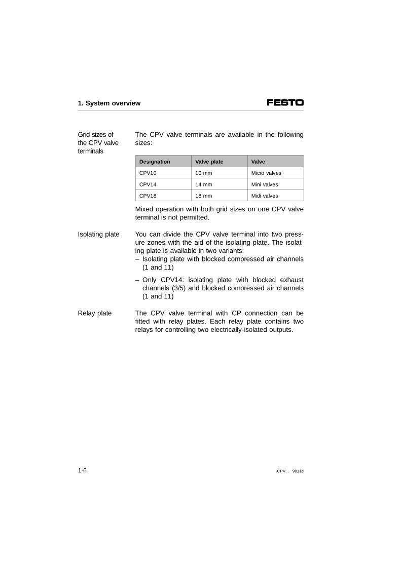
The CPV valve terminals are available in the followingsizes:
Grid sizes ofthe CPV valveterminals
Designation Valve plate Valve
CPV10 10 mm Micro valves
CPV14 14 mm Mini valves
CPV18 18 mm Midi valves
Mixed operation with both grid sizes on one CPV valveterminal is not permitted.
You can divide the CPV valve terminal into two press-ure zones with the aid of the isolating plate. The isolat-ing plate is available in two variants:
Isolating plate
– Isolating plate with blocked compressed air channels(1 and 11)
– Only CPV14: isolating plate with blocked exhaustchannels (3/5) and blocked compressed air channels(1 and 11)
The CPV valve terminal with CP connection can befitted with relay plates. Each relay plate contains tworelays for controlling two electrically-isolated outputs.
Relay plate
1. System overview
1-6 CPV... 9811d

The supply and work tubing can be connected centrallyon CPV valve terminals with the pneumatic multipleconnector plate. The CPV valve terminals can be sep-arated quickly from the supply and work tubing. Bymeans of appropriate end plates, conversion from indi-vidual tubing to tubing with the pneumatic multiple con-nector plate can be made at any time. The pneumaticmultiple connector plate is available in two variants:
Pneumatic multiple connector plate
– Standard design of pneumatic multiple connector plate which fits flush with the end plates of the CPVvalve terminal. The holes for fastening to the wall orfor foot mounting are on the connection side of thepneumatic multiple connector plate.
– Extended pneumatic multiple connector plate with ex-ternal fastening holes.
CPV valve terminal with pneumatic CPV valve terminal with extended multiple connector plate (standard) pneumatic multiple connector plate
1
2
Fastening holes for fitting onto a wall on the standard design of pneumatic multiple connector plate Fastening holes for fitting onto a wall on the extended pneumatic multiple connectorplate
Fig. 1/2: Versions of the pneumatic multiple connector plate
1 2
1. System overview
CPV... 9811d 1-7

1.2 Description of components
The CPV valve terminal consists of the following com-ponents:
1234
56
7890!"
Electrical connector plate with MP, AS-i or CP connectionRight-hand end plate (with/without supply connections or for pneum. m.c. plate)Relay plate (only for CPV10/14 terminals with CP connection) Blanking or isolating plate (with blocked air channels 1 and 11 andexhaust channel (3/5) or only blocked air channels 1 and 11Valve plates fitted with single or double solenoid valvesIdentifying plate and cover of manual override for inscription clips (optional) not inconnection with relay plate Pneumatic multiple connector plate (optional)Left-hand end plate (with/without supply connections or for pneum. m.c. plate)Support for hat-rail mounting (optional) for CPV10/14 or CPV18Support for wall fastening (optional) for CPV10/14 or CPV18 Support for wall fastening (optional) for CPV10/14 Intermediate plug with current reduction
Fig. 1/3: Components of the CPV valve terminal
1
8
2
7
9
3
5
4
6
0
!
"
1. System overview
1-8 CPV... 9811d

By means of the identification code, you can ascertainwhich plates are fitted on your CPV valve terminal. Thiscode is printed on the front between the manual over-rides 12 and 14. The identification codes are as follows:
Identificationcode
Ident. codes Pneumatic component
CDFGH
JLMNRS
T
Valve plate, two 3/2-way, basic position closedValve plate, two 2/2-way, basic position closedValve plate, 5/2-way, single solenoidValve plate, 5/3-way, mid-position blockedValve plate, two 3/2-way, one open in basicposition, one closed in basic position Valve plate, 5/2-way, double solenoidBlanking plate Valve plate, 5/2-way, single solenoidValve plate, two 3/2-way, basic position openRelay plateIsolating plate, exhaust channel (3/5) and airchannels (1, 11) blockedIsolating plate, air channels (1, 11) blocked
The CPV valve terminals are available with the follow-ing valve plates:
Valve plates
Valve plate
Ident. code: D Function: two 2/2-way single solenoid valves
2
12/14 1 3/5 11
82/84 4
11214
1. System overview
CPV... 9811d 1-9

Valve plate (continuing)
Ident. code: N Function:– Two single 3/2-way valves open in
basic position– 5/3-way valve pressurized in mid-position.
This function is implemented with two 3/2-way valves open in basic position.
Ident. code: C Function:- Two 3/2-way valves, blocked in basic
position- 5/3-way valve exhausted in mid-position. This function is implemented with two 3/2-way valves blocked in basic position. - In preparation: 5/3-way valve blocked in
mid-position. This function is implemented on the CPV10/14 terminals with two 3/2-wayvalves blocked in basic position in combination with externally fitted switchablenon-return valves.
PLEASE NOTE• If you are using the 3/2-way valves as a
5/3-way mid-position valve, make sure thatyour control program does not actuate bothvalve solenoid coils of the 3/2-way valves atthe same time, thereby actuating a double-acting cylinder.
Ident. code: H Function:two 3/2-way valves on control side 110 basicposition open and on control side 14 basicposition closed.
24
12/14
1 3/511
82/84
11214
24
12/14
1 3/5 11
82/84
11014
2
12/14
1 3/5 11
82/84 4
11010
1. System overview
1-10 CPV... 9811d

Valve plate (continuing)
Ident. code F (only CPV10 valve terminal)or M
Function: 5/2-way single solenoid valve
PLEASE NOTEObserve the following limitations on using the"F valve plate" (Ident. code F) with CPV valveterminals• With MP connection "F valve plates" may
only occupy every second valve location.• With IC connection "F valve plates" may
only be used with intermediate plugs for current reduction.
• With AS-i connection "F valve plates" mayonly be operated in valve terminals of typeCPV10-GE-ASI-4E4A-... .
• With direct connection "F valve plates" mustnot be operated in valve terminals of typeCPV10-GE-IBL-... .
Ident. code: J Function: 5/2-way double solenoid valve
Ident. code: G only for CPV18 terminal Function: 5/3-way valve blocked in mid-position
2
12/14
13/5
11
82/84 4
14 112
2482/84
12/14
1 11
14 112
3/5
82/84
12/14
1 11
4 2
11214
3/5
1. System overview
CPV... 9811d 1-11

On the CPV valve terminal you will find the followingpneumatic connections and operating elements:
12345678
90
Valve location inscription clip (per valve)Support for inscription clip and cover of manual overrideType plateManual override (per pilot solenoid, automatic reset or locking)Clip of pushing manual overrideRecess for label supportEarth/ground connection (left/right-hand end plate)Supply connections (1, 11, 12/14), exhaust connections (3/5, 82/84):with individual tubing on left and/or right-hand end platewith central tubing on pneumatic multiple connector plateWork connections (2, 4), per valvePneumatic multiple connector plate
Fig. 1/4: Pneumatic connections and operating elements on the CPV valve terminal
PLEASE NOTE Instructions on the electrical connecting elementsand display elements of the CPV valve terminalswith direct connection can be found in the appro-priate electronics manuals.
89
8
0
2
1 3 45
6
8
7
9
1. System overview
1-12 CPV... 9811d

On the CPV valve terminal with IC connections you willfind the following electrical connections and display ele-ments:
1234567
8
Label fields (per cable socket)Intermediate plug for current reduction (optional)Type plate Connecting lugs for pilot solenoid coil 14Earth/ground connection (per end plate)Connecting lugs for pilot solenoid coil 12Yellow LEDs, signal status displays of pilot solenoids(per cable socket)Ready-to use cable with socket for individual connection(per pilot solenoid), can be turned 180°.
Fig. 1/5: Electrical connections and display elementsof the CPV valve terminal with IC connection
1
2
5
76
3
4
1. System overview
CPV... 9811d 1-13

On the CPV valve terminal with MC connection you willfind the following connections and display elements:
1
2345
SUB-D multipin plug ( 9-pin for terminals with 4 valves, 25-pin for terminals with 6 or 8 valves) Label clipYellow LEDs, signal status displays of the pilot solenoidsType plateEarth/ground connection (per end plate)
Fig. 1/6: Electrical connections and display elementsof the CPV valve terminal with MC connection
4
1
3
5
2
1. System overview
1-14 CPV... 9811d

On the CPV valve terminal with CP connection you willfind the following electrical connections and display ele-ments:
123456789
Incoming CP cableContinuing CP cableLabel clipYellow LEDs, signal status display of relaysYellow LEDs, signal status display of the pilot solenoidsRelay connections with cableType plateEarth/ground connection (per end plate)Green LED, Status display of CP connection
Fig. 1/7: Electrical connections and display elementsof the CPV valve terminal with CP connection
9
8
3
7
1 2
6
5
4
1. System overview
CPV... 9811d 1-15

On the CPV valve terminal with AS-i connection you willfind the following electrical connections and display ele-ments:
1
2
34567890
Green LED status display of the inputs(only CPV..-GE-ASI-4E4A-...)Cable socket for additional supply with black supply cable(only CPV..-GE-ASI-.-Z)AS-i bus socket with yellow bus cableSensor cable with plug (only CPV..-GE-ASI-4E4A-...)AS-i cable cap (only CPV..-GE-ASI-.-Z)Label clipYellow LED status displays of the pilot solenoidsType plateEarth/ground connection (per end plate)BUS LED 1 (green),BUS LED 2 (red) (only CPV..-GE-ASI-4E4A-...)
Fig. 1/8: Electrical connections and display elementsof the CPV valve terminal with AS-i connection
1
6
7
2
3
4
5
9
8
0
1. System overview
1-16 CPV... 9811d

Chapter 2
Fitting
2. Fitting
CPV... 9811d 2-1

Contents
2. Fitting
2.1 CPV valve terminal with individual tubing . . . . . . . . . . . . . . . . . 2-32.1.1 Fitting onto a wall . . . . . . . . . . . . . . . . . . . . . . . . . . . . . . . . . . . . 2-42.1.2 Fitting onto a hat rail . . . . . . . . . . . . . . . . . . . . . . . . . . . . . . . . . 2-82.1.3 Fitting with feet . . . . . . . . . . . . . . . . . . . . . . . . . . . . . . . . . . . . . 2-112.1.4 Fitting the CPV valve terminal onto the SIMATIC ET 200X. . . 2-132.2 CPV valve terminal with pneumatic multiple connector plate . 2-162.2.1 Fitting the pneumatic multiple connector plate. . . . . . . . . . . . . 2-172.2.2 Fitting the CPV valve terminal onto the pneumatic
multiple connector plate . . . . . . . . . . . . . . . . . . . . . . . . . . . . . . 2-212.3 Fitting the designation support . . . . . . . . . . . . . . . . . . . . . . . . . 2-22
2. Fitting
2-2 CPV... 9811d

WARNINGBefore undertaking installation or maintenance work,switch off the following:• the compressed air supply• the power supply to the valve solenoid coils
You thereby avoid:
– uncontrolled movements of loose tubing
– unintentional movements of the connected actuators
– undefined switching states of the electronic compo-nents
2.1 CPV valve terminal with individual tubing
The CPV valve terminal with individual tubing has beendesigned for use on a system or machine which is fittedin one of the following ways:
Fitting variants
– Fitting onto a wall
– Fitting onto a hat rail
– Fitting with feet
PLEASE NOTEIf your application is subjected to vibration in excessof the following values: – 0.15 mm travel at 10-58 Hz– 2 g acceleration at 58-150 Hzthe CPV14 or CPV 18 valve terminals should bemounted on a wall or with feet.
2. Fitting
CPV... 9811d 2-3
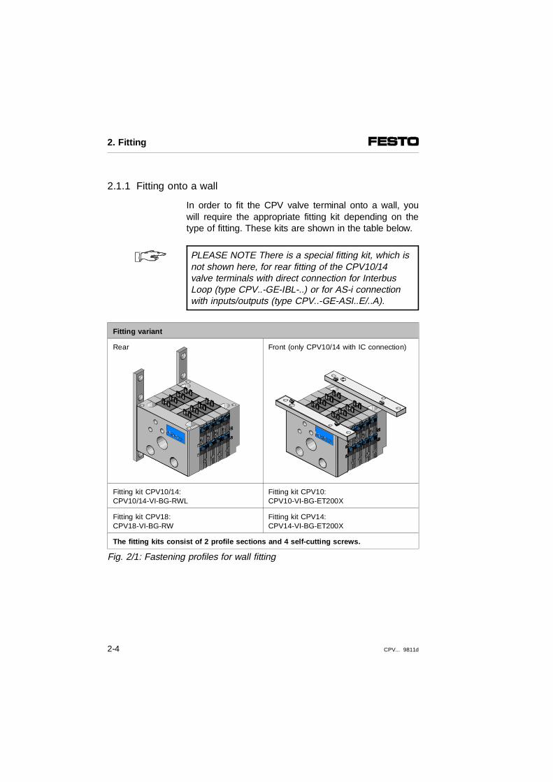
2.1.1 Fitting onto a wall
In order to fit the CPV valve terminal onto a wall, youwill require the appropriate fitting kit depending on thetype of fitting. These kits are shown in the table below.
PLEASE NOTE There is a special fitting kit, which isnot shown here, for rear fitting of the CPV10/14valve terminals with direct connection for InterbusLoop (type CPV..-GE-IBL-..) or for AS-i connectionwith inputs/outputs (type CPV..-GE-ASI..E/..A).
Fitting variant
Rear Front (only CPV10/14 with IC connection)
Fitting kit CPV10/14: CPV10/14-VI-BG-RWL
Fitting kit CPV10: CPV10-VI-BG-ET200X
Fitting kit CPV18: CPV18-VI-BG-RW
Fitting kit CPV14: CPV14-VI-BG-ET200X
The fitting kits consist of 2 profile sections and 4 self-cutting screws.
Fig. 2/1: Fastening profiles for wall fitting
2. Fitting
2-4 CPV... 9811d

Proceed as follows:
• Make sure that the mounting surface can support theweight of the CPV valve terminal.
• Fit the fastening profiles to the left and right handend plates (see Fig. 2/2). Use the self-cutting screwssupplied for this purpose (see table). When fitting thevalve terminal from the rear, make sure that the fix-ing bolts of the profile sections grip into the groove inthe end plates.
Valve terminal
Fitting variant: rear Fitting variant: front
Self-cutting screw Tightening torque Self-cutting screw Tightening torque
CPV10/14 M4 x 10 1.5 Nm M3 x 18 1.5 Nm ± 0.2 Nm
CPV18 M5 x 10 4 Nm ---------- ----------
2. Fitting
CPV... 9811d 2-5

Fitting variant: rear Fitting variant: front
1
23
4
M4 screws (CPV10/14) or M5 screws(CPV18) for wall fittingFixing bolts (only CPV10/14)Self-cutting screws for fastening theprofiles to the CPV valve terminalAdditional self-cutting screw forCPV14/18 valve terminals
12
M5.5 bore for wall fasteningSelf-cutting screws for fastening theprofiles to the CPV valve terminal
Fig. 2/2: Fitting the CPV valve terminal onto a wall
• Make sure that there is enough room to connect thepower cables and the pneumatic tubing. In the caseof front fitting, a suitable spacer or cutout sectionmust be provided to permit access to the electricalconnections (see Fig. 2/3).
PLEASE NOTE The boring dimensions for rear fitting of the CPVvalve terminal (Fig. 2/3) do not apply to theCPV10/14 valve terminals with direct connection forInterbus Loop (type CPV..-GE-IBL-..) or for AS-i con-nection with inputs/outputs (type CPV..-GE-ASI..E/..A).
2
1
341
1
22
2. Fitting
2-6 CPV... 9811d

Fitting variant: rear Fitting variant: front
CPV10 CPV14 CPV18 CPC10 CPV14
1234
92 mm*)
62 mm*)
9 mm10 mm x no.of plates
92 mm*) 62 mm*)
13 mm14 mm x no.of plates
120 mm
15 mm18 mm x no.of plates
123
45
109.5 mm26 mm10 mm x no. ofplates52 mm + 3120 mm*)
109.5 mm10 mm14 mm x no. ofplates20 mm + 120 mm*)
5 18 mm + 4 26 mm + 30 mm + 4 6
7
Cut out wall section if spacer is notused Spacer
*) The following applies with CPV10/14valve terminals:– Dimension 1 for CPV valve terminal
with MP, CP or AS-i connection (without inputs/outputs)
– Dimension 2 for CPV10/14 valve terminals with IC connection
*) Dimension 5 depends on the design ofthe electrical connector sockets
Fig. 2/3: Dimensions for fastening holes/cutout wall section
4
4
1 5
32 2
3
7
1
4
2
5
3 3
2. Fitting
CPV... 9811d 2-7
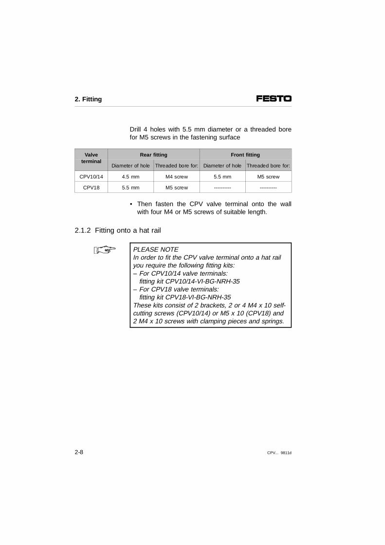
Drill 4 holes with 5.5 mm diameter or a threaded borefor M5 screws in the fastening surface
Valveterminal
Rear fitting Front fitting
Diameter of hole Threaded bore for: Diameter of hole Threaded bore for:
CPV10/14 4.5 mm M4 screw 5.5 mm M5 screw
CPV18 5.5 mm M5 screw ---------- ----------
• Then fasten the CPV valve terminal onto the wallwith four M4 or M5 screws of suitable length.
2.1.2 Fitting onto a hat rail
PLEASE NOTEIn order to fit the CPV valve terminal onto a hat railyou require the following fitting kits: – For CPV10/14 valve terminals:
fitting kit CPV10/14-VI-BG-NRH-35– For CPV18 valve terminals:
fitting kit CPV18-VI-BG-NRH-35These kits consist of 2 brackets, 2 or 4 M4 x 10 self-cutting screws (CPV10/14) or M5 x 10 (CPV18) and2 M4 x 10 screws with clamping pieces and springs.
2. Fitting
2-8 CPV... 9811d

Proceed as follows:
• Make sure that the fastening surface can support theweight of the CPV valve terminal.
• Fit one of the following hat rails:
Hat rail for CPV10/14 terminal Hat rail for CPV18 terminal
Support rail as per EN 50022 - 35 x 7.5 (width 35 mm, height 7.5 mm)
Support rail as per EN 50022 - 35 x 15 (width 35 mm, height 15 mm)
• Make sure that there is enough room to connect thepower cables and the pneumatic tubing.
• Fasten the hat rail to the surface approximately every100 mm.
• Screw the 2 brackets onto the end plates with thescrews supplied, as shown in the diagram below.With the CPV10/14 valve terminals, make sure thatthe fixing bolts of the brackets grip into the recess inthe CPV valve terminal.
CP terminal Self-cutting screws Tightening torque
CPV10/14 M4 x 10 1.5 Nm
CPV18 M5 x 10 4 Nm
2. Fitting
CPV... 9811d 2-9

1
234
For each end plate one M4 x 10 screw (CPV10), two M4 x 10screws (CPV14) or two M5 x 10 screws (CPV18)Hat railHat rail clamping unitFixing bolts (only CPV10/14)
Fig. 2/4: Fitting the valve terminal onto a hat rail
• Hang the CPV valve terminal onto the hat rail. andfasten it on both sides with the hat rail clamping unit.This will prevent it from tilting or slipping.
4
3
1
2
2. Fitting
2-10 CPV... 9811d

2.1.3 Fitting with feet
PLEASE NOTEIn order to fit the CPV valve terminal with feet (at thelevel of work connections 2 and 4) you require thefollowing fastening screws:• 4 M4 x 45 socket head screws (CPV10)• 4 M4 x 50 socket head screws (CPV14) • 4 M6 x 65 socket headscrews (CPV18)
Proceed as follows:
• First you must prepare your fastening surface, andmake a suitable bracket where necessary. The posi-tion and distances between the fastening holes of theCPV valve terminals are shown in the diagrambelow.
CPV 10 terminal CPV 14 terminal CPV 18 terminal
123
53 mm 4 mm10 mm x numberof plates
66 mm 5 mm14 mm x numberof plates
87 mm 8.1 mm18 mm x number of plates
Fig. 2/5: Position of the fastening holes
1
2
3
2
2. Fitting
CPV... 9811d 2-11

• Make sure that there is enough room to connect thepower cables and the pneumatic tubing.
• In the case of CPV terminals with IC connection, youmust insert the 4 socket head screws supplied intothe holes intended for this purpose on the left andright-hand end plates (see diagram).
CPV10 CPV14 CPV18
Socket head screws M4 x 45 M4 x 50 M6 x 65
123
M4 x 45 or M4 x 50 or M6 x 65 socket head screwsEnd platesFastening bracket
Fig. 2/6: Position of fastening screws
• Screw the CPV valve terminal onto the fastening sur-face or onto a support bracket.
3
1
2
2. Fitting
2-12 CPV... 9811d

2.1.4 Fitting the CPV valve terminal onto the SIMATIC ET 200X
PLEASE NOTEInstructions on the decentral periphery device ET200X can be found in the SIEMENS AG manual.
A CPV valve terminal with:
• IC connection
• 8 valve plates
• fitted fastening CPV..-VI-BG-ET200X
• and relevant seals
can be fitted onto a pneumatic interface module of typeEM 148-P-DO 16 x P/CPV.. for the decentral peripherydevice ET200X.
When the device is fitted, the switching status of thevalve solenoid coil can be recognized by the LED onthe pneumatic interface module.
Fitting
Proceed as follows:
1. The fastening is already fitted to the CPV valve ter-minal. Check that the flat seal is placed correctlyover the connecting lugs and the centring bolts be-tween them (see Fig. 2/7).
2. Fitting
CPV... 9811d 2-13

2. Mark the positions of the 4 holes for the fasteningscrews on the base (see diagram). Tip: Hold thepneumatic interface module by the mounting surfaceand mark the position of the holes. Drill the 4 holesfor M5 screws.
1234
Fastening type CPV..-VI-BG-ET200XConnecting lug with centring bolt109.5 mm132 mm
Fig. 2/7: Dimensions for fitting onto the SIMATIC ET200X
3. Place the valve terminal carefully and without tiltingonto the pneumatic interface module. Make surethat:- the holes are placed over the centring bolts- the connecting lugs are not bent. Screw the valve terminal and the pneumatic inter-face module with 4 screws onto the mounting sur-face.
3
4
1
2
2. Fitting
2-14 CPV... 9811d

1
2
M5 screws, length at least 60 mm (ISO 1207/ISO 1580 - DIN84 or DIN 912)Centring bolts
Fig. 2/8: Fitting the CPV valve terminal onto theSiemens SIMATIC ET200X
PLEASE NOTEIn order to remove the CPV valve terminal, lift it upcarefully and without tilting. If the valve terminal isoperated in a dirty environment, the seal should bereplaced. – for CPV10: seal type CPV10-GE-8 – for CPV14: seal type CPV14-GE-8
2
2
1
2
2. Fitting
CPV... 9811d 2-15

2.2 CPV valve terminal with pneumatic multiple connector plate
If you are using a pneumatic multiple connector plate,the power supply and work lines will be connected at acentral point. This enables the supply and work lines tobe disconnected from the CPV valve terminal easilyand quickly.
PLEASE NOTEOnly CPV valve terminals, which have been fittedwith appropriate end plates, may be mounted on thepneumatic multiple connector plate. CPV valve terminals, which have been fitted withend plates for individual tubing, can be converted before they are fitted onto the pneumatic multipleconnector plate. In this case replace the end plates with multiple connector end plates.
The pneumatic multiple connector plate is available intwo variants:
– Standard design of the pneumatic multiple connectorplate which fits flush with the end plates of the CPVvalve terminal. The holes for fastening the valve ter-minal onto a wall or for mounting on feet are on thesame side as the connections on the pneumatic mul-tiple connector plate.
– Extended pneumatic multiple connector plate whichprojects over the end plates. Due to its external fa-stening bores, this plate can be fitted very easily.Two additional holes running transversely throughthis pneumatic multiple connector plate enable thevalve terminal to be fitted by the rear to a wall (seechapter "System summary" Fig. 1/2).
2. Fitting
2-16 CPV... 9811d

2.2.1 Fitting the pneumatic multiple connector plate
Make sure that the mounting surface can support theweight of the pneumatic multiple connector plate andthe CPV valve terminal. Make sure also that there isenough room to connect the power cables and thepneumatic tubing.
Fitting the pneumatic multiple connector plate(connection side)
In order to fit the pneumatic multiple connector plate inthe standard or extended design by the connection sideto a mounting surface, proceed as follows:
• Cut out a section of the mounting surface (dimen-sions see Figs. 2/9 and 2/10).
• Drill four holes in the mounting surface. The positionand distances between these holes is shown in Figs.2/9 and 2/10.
• Fasten the pneumatic multiple connector plate ontothe mounting surface with 4 screws of suitablelength.
Diameter of mounting holes and screw sizes
Pneumatic multiple connector plate(standard version)
Pneumatic multiple connector plate (extended version)
CPV10/14 CPV18 CPV10/14/18
4.5 mm 5.5 mm 6.5 mm
M4 M5 M6
2. Fitting
CPV... 9811d 2-17

Wall cutout dimensions for CPV valve terminals with standard pneumatic multiple connector plate
CPV10/14:
CPV18:
CPV10 terminal CPV14 terminal CPV18 terminal
12345678
29.5 mm + 660 mm55 mmR411.25 mm 10 mm x number of plates31.5 mmDiameter 4.3 mm
39.5 mm + 6 76.6 mm68.6 mmR412.75 mm14 mm x number of plates38.3 mmDiameter 4.3 mm
59.0 mm + 698 mm --------------------------------------------------------------------------25.5 mm18 mm x number of plates54 mmDiameter 5.5 mm
Fig. 2/9: Wall cutout dimensions for the standard pneumatic multipleconnector plate
1
6
7
5 5
2
8
6
7
5 5
23
18 4
2. Fitting
2-18 CPV... 9811d

Wall cutout dimensions for CPV valve terminals with extended pneumatic multiple connector plateCPV10/18
CPV14
CPV10 terminal CPV14 terminal CPV18 terminal
1234567890!"
30 mm + 973 mmR126.3 mm------------------------------------------------------------------------------------------------------21 mm10 mm x number of plates21.5 mm18.5 mmDiameter 6.5 mm
40 mm + 989 mmR149.0 mm4.7 mm5.55 mmR826 mm14 mm x number of plates29.5 mm29.5 mmDiameter 6.5 mm
60 mm +118 mm R2215 mm---------------------------------------------------------------------------------------------------------35.5 mm18 mm x number of plates44 mm44 mmDiameter 6.5 mm
Fig. 2/10: Wall cutout dimensions for the extended pneumatic multipleconnector plate
9
8 8
2
3
1
45
"
7
6
0
!
9
98 8
1
4
"
2
3!
0
2. Fitting
CPV... 9811d 2-19

Fitting the pneumatic multiple connector plate(rear side)
In order to fit the pneumatic multiple connector plate inthe extended version by the rear side to a mountingsurface, proceed as follows:
• Drill 2 holes in the mounting surface for M6 screws.The position of and distance between these holescan be seen in Fig.2/11.
Dimension 1
Number ofvalve locations
CPV10 CPV14 CPV18
2 62 mm 80 mm 107 mm
4 82 mm 108 mm 143 mm
6 102 mm 136 mm 179 mm
8 122 mm 164 mm 215 mm
Fig. 2/11: Hole dimensions for rear fitting
• Screw the pneumatic multiple connector plate ontothe mounting surface with two M6 screws of suitablelength.
1
2. Fitting
2-20 CPV... 9811d

2.2.2 Fitting the CPV valve terminal onto the pneumatic multiple connector plate
Proceed as follows:
• In the case of CPV valve terminals with individualconnection, insert the socket head screws suppliedinto the fastening holes of the CPV valve terminal. Inthe case of CPV valve terminals with MP, AS-i or CPconnection, the socket head screws are already in-serted with a retaining device in the fastening holesunder the electrical connector plate.
• Place the 3-seal or 4-seal strips for sealing the sup-ply channels into the grooves in the left or right-handend plate.
• In order to seal the work channels, carefully pressthe 2 individual seals into the threads of the workconnections.
• Screw the CPV valve terminal onto the pneumaticmultiple connector plate with the 4 socket headscrews. Tighten the screws in diagonally opposite se-quence with 2 Nm (CPV10/14) or 4 Nm (CPV18).
Fig. 2/12: Fitting the CPV valve terminal onto the pneumatic multiple connector plate
2. Fitting
CPV... 9811d 2-21
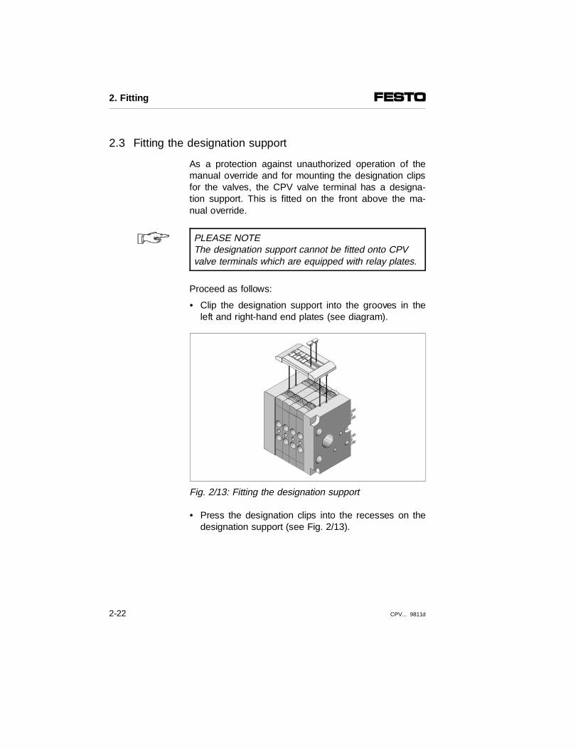
2.3 Fitting the designation support
As a protection against unauthorized operation of themanual override and for mounting the designation clipsfor the valves, the CPV valve terminal has a designa-tion support. This is fitted on the front above the ma-nual override.
PLEASE NOTEThe designation support cannot be fitted onto CPVvalve terminals which are equipped with relay plates.
Proceed as follows:
• Clip the designation support into the grooves in theleft and right-hand end plates (see diagram).
Fig. 2/13: Fitting the designation support
• Press the designation clips into the recesses on thedesignation support (see Fig. 2/13).
2. Fitting
2-22 CPV... 9811d

Chapter 3
Installation
3. Installation
CPV... 9811d 3-1

Contents
3. Installation
3.1 General connecting principles . . . . . . . . . . . . . . . . . . . . . . . . . . 3-33.2 Connecting the CPV valve terminal . . . . . . . . . . . . . . . . . . . . . . 3-53.2.1 Auxiliary pilot air . . . . . . . . . . . . . . . . . . . . . . . . . . . . . . . . . . . . . 3-63.2.2 Connecting the supply and work tubing . . . . . . . . . . . . . . . . . . . 3-83.2.3 Connecting the electrical cables. . . . . . . . . . . . . . . . . . . . . . . . 3-11
3. Installation
3-2 CPV... 9811d

3.1 General connecting principles
WARNINGBefore undertaking installation or maintenance work,switch off the following:• the compressed air supply• the power supply to the valve solenoid coils
You thereby avoid:
– uncontrolled movements of loose tubing
– unintentional and sudden movements of the con-nected actuators
– undefined switching states of the electronic compo-nents
Please observe the following:The components on the valve terminal contain electros-tatically vulnerable components. Do not touch the con-tact surfaces of the plug connnectors. These compo-nents may be damaged if the regulations for handlingelectrostatically vulnerable components are not ob-served.
Laying the pneumatic tubing
PLEASE NOTE• If necessary, place a seal under the screw
connectors or silencers in order to avoid leakage.– If elbow connectors or multiple distributors are
used, the air flow will usually be reduced.
3. Installation
CPV... 9811d 3-3
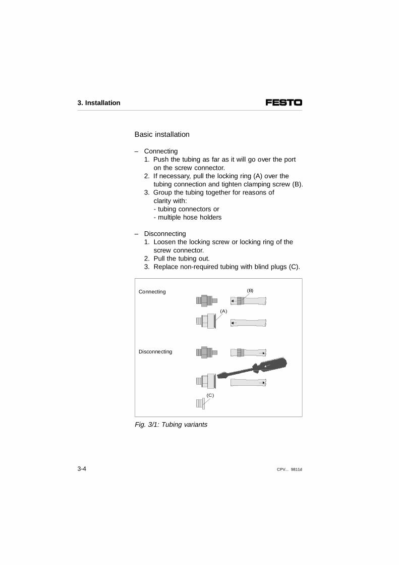
Basic installation
– Connecting1. Push the tubing as far as it will go over the port
on the screw connector.2. If necessary, pull the locking ring (A) over the
tubing connection and tighten clamping screw (B).3. Group the tubing together for reasons of
clarity with:- tubing connectors or - multiple hose holders
– Disconnecting1. Loosen the locking screw or locking ring of the
screw connector.2. Pull the tubing out.3. Replace non-required tubing with blind plugs (C).
Connecting
Disconnecting
Fig. 3/1: Tubing variants
(B)
(A)
(C)
3. Installation
3-4 CPV... 9811d

3.2 Connecting the CPV valve terminal
PLEASE NOTE• If valves are fitted but not used, seal the work con-nections
2 and 4 with blind plugs.• Depending on the tool you are using, observe
the following sequence when you connect the work lines:- if using a socket head wrench, you can connect the work lines in any sequence.- if using an external socket head wrench, you must connect the work lines from left to right (room for wrench).
In order to guarantee optimum efficiency of your CPVvalve terminal, we recommend that the compressed airand, if necessary, the exhaust lines be connected onboth sides in the following cases:
– when large-volume cylinders are to be operated athigh speed
– when several valves are switched simultaneously tothrough flow
PLEASE NOTE• Connect the supply pressure to both sides of the
end plates or pneumatic multiple connector plate, if the CPV valve terminal is operated with two pressure zones.
3. Installation
CPV... 9811d 3-5

3.2.1 Auxiliary pilot air
CAUTIONOperate the CPV valve terminal only with the me-dium described below.– If possible, use non-lubricated auxiliary pilot air
(connections 12/14). Otherwise use hydraulic oil of type DIN 51524-HLP32/ISO 6743-4. The oil content in the auxiliary pilot air must not exceed 3-5 drops per 1000 l of air consumed. This corresponds to 6 bar supply pressure and a medium flow rate of approximately 1 drop/4 minutes.Observe the instructions on special oil for serviceunits in the Festo Pneumatics Catalogue.
– In the case of CPV valve terminals with internallybranched auxiliary pilot air, the above mentioned instruction also applies to the supply air (connection 1/11).
The CPV valve terminal is intended for internal or exter-nal pilot air, depending on the end plates. Refer to yourorder documentation or to the table in chapter 5.3 "In-ternal/external pilot air" to see which end plates arefitted on your CPV valve terminal.
If the supply pressure of your CPV valve terminal isbetween 3 and 8 bar, you can work with internal auxi-liary pilot air. In this case the auxiliary pilot air is takenfrom port 1 or 11 on the left or right-hand end plate.
Internalpilot air
PLEASE NOTEIf you are using a CPV valve terminal with internalpilot air: – port 12/14 must be sealed with a blind plug.
3. Installation
3-6 CPV... 9811d

If the supply pressure of your CPV valve terminal is inthe range 3 to 8 bar, you must operate it with externalpilot air. In this case the external pilot air is supplied viaport 12/14 on the CPV valve terminal.
Externalpilot air
PLEASE NOTE• Use regulated external pilot air (3 to 8 bar).
This will ensure reliable faultless and operation of the CPV valve terminal.
• Ensure that the regulated external pilot air is supplied or taken at only one point by means of common tubing for all valve plates on the CPV valve terminal. This also applies when the CPV valve terminal is operated with different pressure zones (see diagram).
1234
Isolating plateBlind plugPressure zone 2Pressure zone 1
Fig. 3/2: Auxiliary pilot air
34
1
2
3. Installation
CPV... 9811d 3-7

3.2.2 Connecting the supply and work tubing
Fit the screw connectors or silencers as shown in thetable below. Then connect the tubing.
With pneumatic multiple connector plate Without pneumatic multiple connector plate
Connection codeISO 5599
Tubing Connection size ISO 228,Specifications in bracketsfor extended pneum. multiple connector plate
Connection
CPV10 CPC14 CPV18
1 or 11 Compressed air/vacuum
G 1/8 G 1/4 G 3/8 Screw connector in endplates or pneumaticmultiple connector plate
2 or 4 Work air/vacuum M7 G 1/8 G 1/4 Screw connector
3/5 Exhaust right/left-hand end platePneum. multiple connector plate
G 3/8
G 1/4
G1/2
G3/8
G 1/2
G 1/2
Screw connector- for ducted exhaust air- for silencers
12/14or
82/84
Auxiliary pilot air/exhaust right/left-hand end platePneum. multiple connector plate
M5
M7 (M5)
G 1/8
G 1/8
G 1/4
G 1/4
Screw connector onconnection 82/84- for ducted exhaust air- for silencers
Fig. 3/3: Assigning the connections
3/5
3/5
114
22
4 11
1
82/84
82/84
12/14
1
1
12/14
11
3. Installation
3-8 CPV... 9811d

PLEASE NOTEIf there are several systems with ducted exhaustair, use non-return valves in the common exhausttubing, in order to avoid impairment of function as a result of back pressures.
123456
CPV valve terminal 1Common 3/5Central 82/84Central 3/5CPV valve terminal 2Common 82/84
Fig. 3/4: Common tubing with non-return valves
PLEASE NOTEThe exhaust channels 3 and 5 are combined in theCPV valve terminal. Separate exhaust restriction ofchannels 3 and 5 is not therefore possible.
1 2 3 4 5
26
6
2
3. Installation
CPV... 9811d 3-9

PLEASE NOTEIn the case of CPV valve terminals with two pressurezones and auxiliary pilot air taken internally on theright-hand side, the pressure on the right-hand sidemust be between 3 bar and 8 bar.
PLEASE NOTEIn the case of CPV valve terminals with ducted sup-ply air, connections 11 and 12/14 must be sealedwith blind plugs.
Vacuum/low pressure operation
The CPV valve terminal can be operated with vacuumor low pressure (< 3 bar), providing regulated auxiliarypilot air is supplied separately A summary of the endplates required can be found in chapter 5 under "Con-version from internal to external auxiliary pilot air").
3. Installation
3-10 CPV... 9811d
3.2.3 Connecting the electrical cables
Information on the procedure, as well as on connectingcables and current requirements can be found in themanual "CP system, installation and commissioning."
WARNINGUse only power units which guarantee reliable isolation of the operating voltages as per IEC 742/EN 60742/VDE 0551 with at least 4 kV isolation resistance (protected extra low voltage, PELV).Switch power packs are permitted providing theyguarantee reliable isolation in accordance with EN 60950/VDE 0805.
Remark: By using PELV power units, protection against electricshock (protection against direct and indirect contact) inaccordance with EN 60204-1/IEC 204 is guaranteed onFesto valve terminals. Safety transformers with the ad-jacent designation must be used for supplying PELVnetworks. The valve terminals must be earthed in orderto ensure their function (e.g. EMC).
PLEASE NOTECheck your EMERGENCY STOP circuitry, to seewhich measures are required in order to place yourmachine/system in a safe state in the event of anEMERGENCY STOP (e.g. switching off the powersupply to the valves and output modules, switchingoff the compressed air supply).
3. Installation
CPV... 9811d 3-11
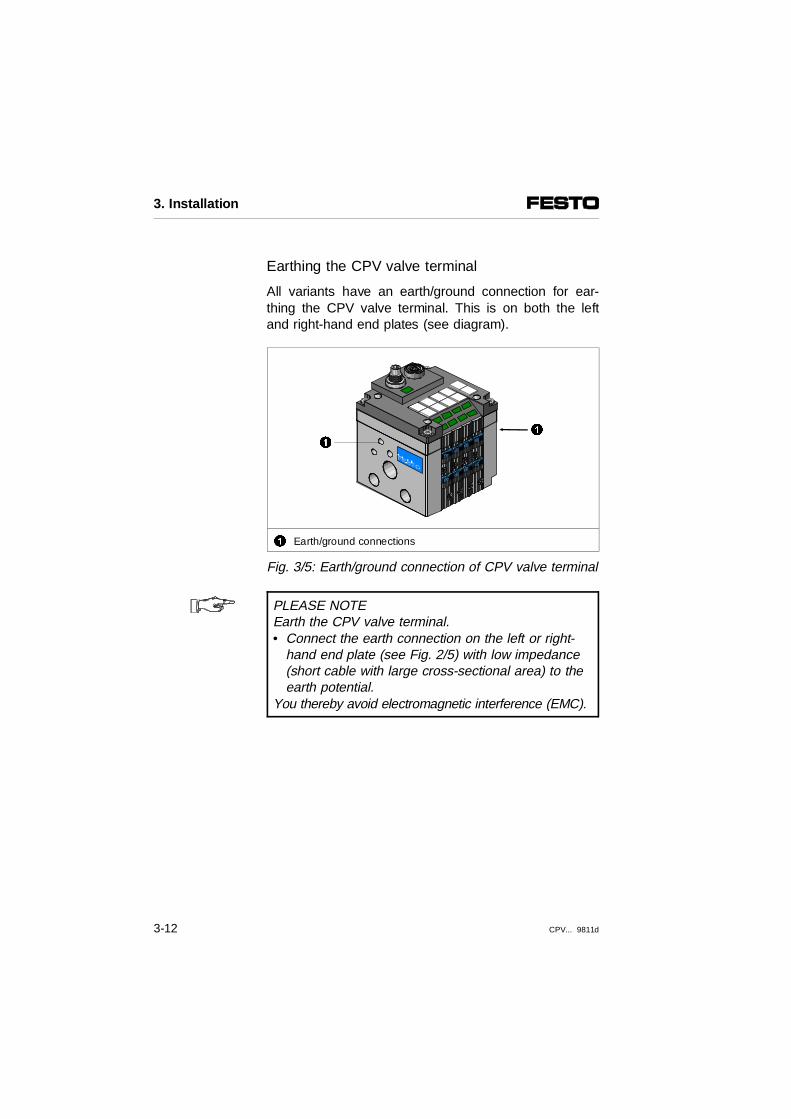
Earthing the CPV valve terminal
All variants have an earth/ground connection for ear-thing the CPV valve terminal. This is on both the leftand right-hand end plates (see diagram).
1 Earth/ground connections
Fig. 3/5: Earth/ground connection of CPV valve terminal
PLEASE NOTEEarth the CPV valve terminal.• Connect the earth connection on the left or right-
hand end plate (see Fig. 2/5) with low impedance(short cable with large cross-sectional area) to theearth potential.
You thereby avoid electromagnetic interference (EMC).
11
3. Installation
3-12 CPV... 9811d
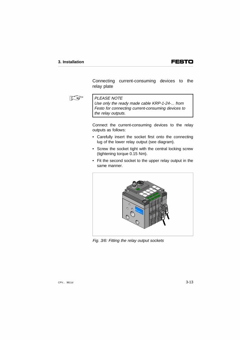
Connecting current-consuming devices to therelay plate
PLEASE NOTEUse only the ready made cable KRP-1-24-... fromFesto for connecting current-consuming devices tothe relay outputs.
Connect the current-consuming devices to the relayoutputs as follows:
• Carefully insert the socket first onto the connectinglug of the lower relay output (see diagram).
• Screw the socket tight with the central locking screw(tightening torque 0.15 Nm).
• Fit the second socket to the upper relay output in thesame manner.
Fig. 3/6: Fitting the relay output sockets
3. Installation
CPV... 9811d 3-13

CPV valve terminal with individual connection
With this CPV valve terminal variant each valve sole-noid coil is connected separately.
PLEASE NOTE• Use only the following pre-assembled Festo
connecting sockets for connecting the valve solenoid coils.– KMYZ-3-24-...-LED / KMYZ-5-24-...-LED. An LED is
incorporated in the transparent plugs of each ofthese connecting sockets. The LED indicates theswitching status of the valve solenoid coil.
– KMYZ-4-24-... .This socket offers a low-costalternative. There is no LED in the plug, butit complies with protection class IP40.
Address assignment of the valves
• The addresses must be assigned in ascending orderwithout gaps
• A valve location always occupies two addresses(even if it is occupied by a reserve, isolating or relayplate)
• Counting begins from left to right, on the individualvalve plates from the front to the rear (see Fig. 3/7)
Fig. 3/7: Address assignment of the CPV valve terminalwith IC connection and 8 valve locations
3. Installation
3-14 CPV... 9811d

Connect the valve solenoid coils as follows:
• For current reduction, insert the intermediate pluginto the connecting lug of the appropriate pilot sole-noid.
• Insert the socket into the connecting lugs of the ap-propriate pilot solenoid or of the intermediate lug(see diagram). The socket can be turned 180°. Makesure that the centring bolt grips into the hole in thesocket between the connecting lugs. Fasten thesocket with the central locking screw (tighteningtorque 0.3 Nm).
Fig. 3/8: Fitting the sockets for individual connection
3. Installation
CPV... 9811d 3-15
CPV valve terminal with multipin or AS-i connection
Connecting the multipin or AS-i cable
PLEASE NOTEDetailed instructions on the electrical installation ofthe CPV valve terminal with multipin or AS-i connec-tions can be found with the relevant product.
CP terminal with CP connection
Connecting the CP cable
PLEASE NOTEDetailed instructions on the electrical installation ofthe CPV valve terminal with CP connection can befound in the manual "CP system – General installa-tion and commissioning", chapter 3.
CP terminal with direct connection
Connecting the field bus cable
PLEASE NOTEDetailed instructions on the electrical installation ofthe CPV valve terminal with direct connection can befound in the manual "CPV valve terminal with directconnection."
3. Installation
3-16 CPV... 9811d

Chapter 4
Commissioning
4. Commissioning
CPV... 9811d 4-1

Contents
4. Commissioning
4.1 General instructions . . . . . . . . . . . . . . . . . . . . . . . . . . . . . . . . . . 4-34.2 Testing the valves. . . . . . . . . . . . . . . . . . . . . . . . . . . . . . . . . . . . 4-44.2 Locating faults. . . . . . . . . . . . . . . . . . . . . . . . . . . . . . . . . . . . . . 4-10
4. Commissioning
4-2 CPV... 9811d

4.1 General instructions
Before commissioning
•• Switch off the power supply before connecting or dis-connecting plugs (otherwise functioning may be im-paired).
•• Earth the CPV valve terminal at an end plate.
•• Commission only a completely fitted and wired valveterminal.
•• Make sure that there is a sufficient supply of air(cooling) for the following operating conditions:- when the maximum number of valves are fitted- when operating at maximum voltage- when the solenoid coils are under constant stress.
4. Commissioning
CPV... 9811d 4-3

4.2 Testing the valves
PLEASE NOTEBefore commissioning the CPV valve terminal, observe the specifications on medium, see chapter "Installation", section 3.2.1 Auxiliary pilot air.
Proceed as follows when commissioning the CPV valveterminal:
Commissioning variants Activity
Preliminary test of the pneumatic tubing
Test the valve-cylindercombination with the manualoverride.
Complete commissioning of thecomplete system
Install and connect the completesystem. Program control by PLC/industrial PC.
There now follows a description of how to commissionthe pneumatic components with the manual override.Commissioning the CP system is described in the ap-propriate manual for the CP node.
4. Commissioning
4-4 CPV... 9811d
Checking the valve functions
Manual override
WARNINGBefore operating the manual override:•• Disconnect the operating voltage supply to the
valve solenoid coils by unplugging the contact (IC, MP AS-i or CP connection).You then avoid undesired actuation of the valvesolenoid coils.
•• Before applying the operating voltage, make surethat all manual overrides are set again at their basic positions.You then avoid undefined switching states of the valves.
You should use the manual override principally whencommissioning the pneumatic system, in order to checkthe functioning and effectiveness of the valve or valve-cylinder combination.By actuating the manual override, you can switch thevalve without an electrical signal. Only the compressedair supply needs to be switched on.
4. Commissioning
CPV... 9811d 4-5

Different types of manual override
The manual override is intended for use as follows:
Manual override design Mode of operation
Manual override with automatic reset (pushing)
Manual override is reset by springforce.
Manual override locking Manual override remains active,until it is reset by hand.
The following types of manual override can be usedwith the CPV valve terminal.
Locking manual override Manual override with automatic reset
Slide of locking manual override to pilotsolenoid 14
Slide of locking manual override to pilot solenoid 12
Button of automatic reset manual overrideto pilot solenoid 14
Button of automatic reset manual overrideto pilot solenoid 12
Fig. 4/1: Different types of manual override
4. Commissioning
4-6 CPV... 9811d
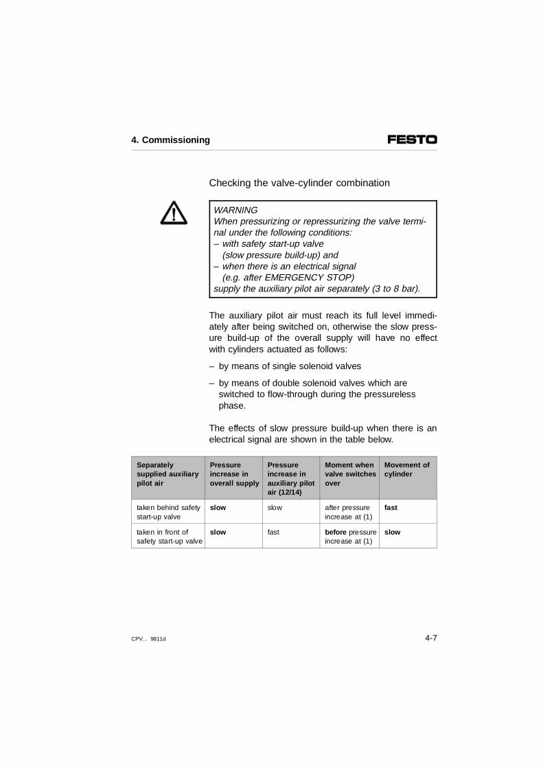
Checking the valve-cylinder combination
WARNINGWhen pressurizing or repressurizing the valve termi-nal under the following conditions:– with safety start-up valve
(slow pressure build-up) and – when there is an electrical signal
(e.g. after EMERGENCY STOP)supply the auxiliary pilot air separately (3 to 8 bar).
The auxiliary pilot air must reach its full level immedi-ately after being switched on, otherwise the slow press-ure build-up of the overall supply will have no effectwith cylinders actuated as follows:
– by means of single solenoid valves
– by means of double solenoid valves which areswitched to flow-through during the pressureless phase.
The effects of slow pressure build-up when there is anelectrical signal are shown in the table below.
Separately supplied auxiliary pilot air
Pressureincrease inoverall supply
Pressureincrease inauxiliary pilotair (12/14)
Moment whenvalve switchesover
Movement ofcylinder
taken behind safetystart-up valve
slow slow after pressureincrease at (1)
fast
taken in front ofsafety start-up valve
slow fast before pressureincrease at (1)
slow
4. Commissioning
CPV... 9811d 4-7

PLEASE NOTE •• Use a blunt pointed object for actuating the
manual override with automatic reset.•• Actuate the manual override with max. 30 N. You thereby avoid functional interference or damageto the manual override.
Proceed as follows:Testing
•• Switch on the compressed air supply.
•• Check the functioning and mode of operation of eachindividual valve cylinder combination with the manualoverride as shown in the diagrams below.
•• When the test is finished, switch off the compressedair supply again.
Actuate the manual override with automatic reset (pushing)
Reaction of valve
Carefully press theplunger of the manualoverride as far as itwill go.
The valve:– switches.
Hold the plunger ofthe manual overridepressed down.
– remains switched
Release plunger.Spring resets theplunger to basicposition.
– returns to basic position(not with 5/2-way double solenoid valve, Ident. code J)
4. Commissioning
4-8 CPV... 9811d

CAUTIONBefore commissioning the CPV valve terminal, returnthe manual override to basic position.
Actuate the manual override with locking Reaction of valve
Push the slide of themanual override downas far as possible.
The valve:– switches
Leave slide in lowerposition.
– remains switched
Push the slide of themanual override up asfar as possible.
– returns to basic position(not with 5/2-way double solenoid valve, Ident. code J)
4. Commissioning
CPV... 9811d 4-9

4.2 Locating faults
Impairment of function
When you switch on the compressed air supply orwhen you have tested the individual valves, you canlearn the following about the operating status of thepneumatic system.
Operating status of the pneumatic system
Valve position Error treatment when compressedair has been switched off
Air comes out...– of common tubing
connections– of work tubing connections
– between the modules
– basic position
– switch position
– basic position
• Check the seal or tubing fitting
• When switching on again regulate separate auxiliary pilot air 3 to 8 bar
Valve or pneumatic system – does not react as expected
– does not react
– does not react
– switch position
– switch position
– basic position
• Check tubing
• When switching on again,check operating pressure(e.g. pressure zones)
• Return for servicing– Check regulator connection
(apply pressure > 3 bar to regulator)
4. Commissioning
4-10 CPV... 9811d
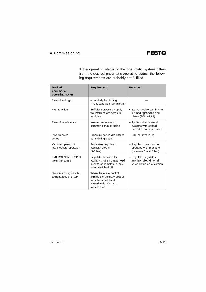
If the operating status of the pneumatic system differsfrom the desired pneumatic operating status, the follow-ing requirements are probably not fulfilled.
Desired pneumatic operating status
Requirement Remarks
Free of leakage – carefully laid tubing– regulated auxiliary pilot air
—
Fast reaction Sufficient pressure supplyvia intermediate pressuremodules
• Exhaust valve terminal atleft and right-hand end plates (3/5 , 82/84)
Free of interference Non-return valves incommon exhaust tubing
– Applies when several systems with central ducted exhaust are used
Two pressure zones
Pressure zones are limitedby isolating plate
– Can be fitted later
Vacuum operation/low pressure operation
Separately regulatedauxiliary pilot air (3-8 bar)
– Regulator can only be operated with pressure (between 3 and 8 bar)
EMERGENCY STOP of pressure zones
Regulator function forauxilary pilot air guaranteedin spite of complete supplybeing switched off
– Regulator regulates auxiliary pilot air for all valve plates on a terminal
Slow switching on afterEMERGENCY STOP
When there are control signals the auxiliary pilot airmust be at full levelimmediately after it isswitched on
4. Commissioning
CPV... 9811d 4-11

LED display of valves
There is a yellow LED for each valve solenoid coil. ThisLED indicates the switching status of the valve solenoidcoil when the CPV valve terminal is ready to operate.
PLEASE NOTEObserve the assignment of the LED to the appropriate manual override: With IC connection:– LED in front plug to
upper manual override (14) – LED in rear plug to
lower manual override (12) With MP, AS-i or CP connection:– lower LED in plug cover to
upper manual override (14) – upper LED in plug cover to
lower manual override (12)
4. Commissioning
4-12 CPV... 9811d

The relationship of the LEDs to the manual override isshown in the diagram below.
12
LEDs and manual override for pilot solenoid 14LEDs and manual override for pilot solenoid 12
Fig. 4/2: Relationship of the LEDs to the manual override
2
2
1
1
4. Commissioning
CPV... 9811d 4-13

The LEDs show the switching status of the valve sole-noid coils. The meaning of the LEDs is shown in thetable below.
LED Switching position of valve Meaning
Yellow out Basic position Logic 0 (signal not applied)
Yellow alight – Switch position or– basic position
Logic 1 (signal applied)
Logic 1 but:– operating voltage of outputs is
below permitted tolerance range (DC 20.4 V to 26.4 V)
or– compressed air supply not correct
or– pilot exhaust blocked
or– return for servicing
4. Commissioning
4-14 CPV... 9811d

Chapter 5
Maintenance and conversion
5. Maintenance and conversion
CPV... 9811d 5-1

Contents
5. Maintenance and conversion
5.1 Fitting/removing CPV valve terminal components . . . . . . . . . . . 5-35.1.1 Removing components from valve locations . . . . . . . . . . . . . . . 5-45.1.2 Fitting components into the valve locations . . . . . . . . . . . . . . . . 5-75.2 Conversion from automatic reset manual override to
locking manual override . . . . . . . . . . . . . . . . . . . . . . . . . . . . . 5-135.3 Conversion from internal to external pilot air . . . . . . . . . . . . . 5-145.4 Conversion from individual to central tubing . . . . . . . . . . . . . . 5-205.5 Converting the CPV valve terminal to two pressure zones . . . 5-215.6 Converting the CPV valve terminal to
different electrical connections . . . . . . . . . . . . . . . . . . . . . . . . . 5-22
5. Maintenance and conversion
5-2 CPV... 9811d

5.1 Fitting/removing CPV valve terminal components
WARNINGBefore fitting, switch off the following:• the compressed air supply• the power supply to the valve solenoid coils
You thereby avoid:
– Uncontrolled movements of loose tubing.
– Sudden and undesired movements of the connectedactuators.
– Undefined switching states of the electronic compo-nents.
5. Maintenance and conversion
CPV... 9811d 5-3

5.1.1 Removing components from valve locations
The components on the CPV valve terminal can easilybe removed for maintenance and conversion work.
Proceed as follows:
1. Loosening the electrical connections:
– MP, AS-i or CP connections• Loosen the multipin plug, the AS-i or CP plug
and carefuly disconnect it.• Then loosen the four fastening screws on the
electrical connector plate. Pull the electrical connector plate away from the connecting lugson the valve plates.
• Remove, if necessary, the plugs on the relay outputs of CPV valve terminals with CP connection. To do this, loosen first the locking screws of the upper plugs. Carefully pull the plug away from the connecting lugs. Then loosen the lower plugs in the same manner.
– IC connection of valve solenoid coils• Loosen the locking screws on the connector
plugs of the valve plates in order to removethem.
• Pull the plugs and, where applicable, theintermediate plug for current reduction carefully away from the connecting lugs.Mark the sockets.
• In the case of CPV valve terminals with pneumatic multiple connector plate, we recommend that the connector plugs be removed from each valve plate.
5. Maintenance and conversion
5-4 CPV... 9811d

2. Loosening the pneumatic connections
• Individually wired CPV valve terminals (without pneu-matic multiple connector plate):Loosen the work tubing of the valve plate which is tobe removed.
3. Loosening the CPV valve terminal from the mountingsurface.
– CPV valve terminals with pneumatic multiple con-nector plate
• Loosen the fastening screws of the pneumaticmultiple connector plate in the left and right-hand endplates one turn in diagonally opposite sequence.Then remove the screws completely. Now removethe CPV valve terminal from the pneumatic multipleconnector plate.
– CP valve terminals with foot fastening
• Loosen the fastening screws in the right-hand endplate and remove them.
– CP valve terminal fitted onto a wall or hat rail
• Loosen the right-hand wall fastening or hat railclamping unit.
5. Maintenance and conversion
CPV... 9811d 5-5

4. Removing the components.
• Loosen both lower tie rods one turn.
• Then loosen the upper tie rod and pull it over thecomponents which are to be replaced.
• Unscrew the two lower tie rods until the heads of thescrews are flush with the outer surface of the endplate (do not remove the tie rod).
• Pull the valve terminal apart so that the distance be-tween the component to be replaced and the nextcomponent is in each case 2 mm.
123
Component to be replacedTie rodGap approx. 2 mm
Fig. 5/1: Removing the valves
1
2
3 3
5. Maintenance and conversion
5-6 CPV... 9811d

• Turn the component forwards around the front tierod.
12
Front tie boltRear tie bolt
Fig. 5/2: Position of the tie bolt
• Pull the component so that it snaps out of the fronttie bolt.
5.1.2 Fitting components into the valve locations
Proceed as follows:
1. Fitting components
• Check that the seals are fitted correctly between theterminal components. They must lie accurately in theappropriate seal grooves.
1 2
5. Maintenance and conversion
CPV... 9811d 5-7

PLEASE NOTE– To equip the CPV10 Valve Terminal with "F valve
plates" (Ident. code F), please note the assemblyand application references in the "System Overview"chapter under "Valve Plate Overview".
– Note that only CPV valve terminals with a CPconnector can be assembled with relay plates (Ident. code R).
• Only CPV10/14 valve terminals: Check that the sealsare seated correctly when valve plates with pneu-matic springs or double solenoid valves are fitted.The seating is not symmetrical (see diagram).
Pneumatic spring valve (Ident code M):Designation "L" on the sealmust point forwards.
Double solenoid valve (Ident code J):Designation "J" on the seal must point forwards.
The flat seal for valve plates with 3/2-wayvalves (Ident code C, H and N) as well asfor all end plates is symmetrical and markedwith 3/2.
Fig. 5/3: Position and designation of seals with pneumatic spring valves ordouble solenoid valves (only CPV10/14 valve terminals)
5. Maintenance and conversion
5-8 CPV... 9811d

PLEASE NOTEThere is only one version of the seal for all valveplates of the CPV18 valve terminal. The position ofthe seal is the same for all valve plates.
• Place the components on the front tie rod. Press thecomponents down so that they snap into the tie rod.
• Swing the components carefully backwards. Makesure there is sufficient space for the flat seals.
• Push the upper tie rod as far as possible into theCPV valve terminal and screw it in a few turns.
• Align the components of the CPV valve terminal on aflat surface so that they are not offset against eachother.
• Tighten first the upper tie rod and then the lower tierod with 0.3 Nm. Then tighten both tie rods with2 Nm.
5. Maintenance and conversion
CPV... 9811d 5-9

– With MP, AS-i or CP connections
PLEASE NOTEThe flat seals between the valve block and the con-necting plate have been modifed. Replace the gluedflat seals if they are more than one year old. Youthereby guarantee reliable sealing on your CPVvalve terminal.
• The flat seals are seated at the bottom of the electri-cal connector plate (see digram).
• Remove the self-adhesive flat seal from the recess.To do this, carefully loosen a corner of the seal (seeFig. 5/4) with the aid of a screwdriver. Then carefullypull the seal away from the electrical sub-base.
1 Flat seals
Fig. 5/4: Position of the flat seal on the electricalconnector plate
1
5. Maintenance and conversion
5-10 CPV... 9811d

• The new single-part flat seal is no longer glued to thebottom of the electrical sub-base, but simply placedon the connecting lugs of the valve solenoid coils(see diagram).
1 New flat seal
Fig. 5/5: Flat seal
• Place the end cover on the connecting lugs of thevalve block. Carefully press down the end cover.
• Tighten the screws of the electrical connector plate indiagonally opposite sequence with 0.6 Nm(CPV10/14) or with 3 Nm (CPV18).
– CPV valve terminals with CP connection and relayplates
• Fit the plugs onto the relay outputs as describedunder "Connecting current-consuming devices to therelay plate."
1
5. Maintenance and conversion
CPV... 9811d 5-11
2. Fitting the CPV valve terminal
CPV valve terminal with pneumatic multiple connectorplate
• Place the 3-seal and 4-seal strips in the recesses inthe left or right-hand end plate. Press the 2-sealstrips carefully into the threads of the work connec-tions.
• Place the CPV valve terminal on the pneumaticmultiple connector plate and tighten the fasteningscrews in the left and right-hand end plates with 0.3Nm. Then tighten the screws in diagonally oppositesequence with 2 Nm (CPV10/14) or with 4 Nm(CPV18).
CP terminal with foot fastening
• Insert the fastening screws in the right-hand endplate and tighten the terminal.
CPV valve terminal with wall or hat rail fastening
• Fix the right-hand fastening onto the wall with twoM4 screws or tighten the right-hand hat rail clampingunit.
3. Fitting the pneumatic and electrical connections
• Fit the connections in the reverse sequence to thatdescribed in "Removing CPV valve terminal compo-nents".
5. Maintenance and conversion
5-12 CPV... 9811d

5.2 Conversion from automatic reset manual override tolocking manual override
By removing a safety clip, you can convert your CPVvalve terminal from automatic reset manual override tolocking manual override. Proceed as follows:
If you do not wish to use the safety clip again:
• Use a screwdriver to press in the centre of the safetyclip, as shown in 1. The safety clip will then bendand can be removed from the fastening.
If you wish to use the safety clip again:
• Use a thin object (e.g. a spatula) to lift the safety clipout of the fastening as shown in 2.
12
Remove the safety clip by pressing it outRemove the safety clip by lifting it out (clip can be used again)
Fig. 5/5: Safety clip of the manual override
1 2
5. Maintenance and conversion
CPV... 9811d 5-13

5.3 Conversion from internal to external pilot air
By fitting the appropriate left and right-hand end platesyou can convert your CPV valve terminal to internal orexternal pilot air.
PLEASE NOTEMixed operation of the CPV valve terminal with inter-nal and external control air is not permitted. The auxi-liary pilot air channel is not divided into two pressurezones by the optionally available isolating plate.
You can ascertain which end plates are fitted on yourCPV valve terminal by means of the part numbers (po-sition see below). In the case of CPV valve terminalswith AS-i, CP or MP connections, the electrical connec-tor plate must be dismantled.
Part number
Designation Part number
CPV10 CPV14 CPV18
CPV..-EPLCPV..-EPL-ECPV..-EPL-GCPV..-EPL-PECPV..-EPL-PG
CPV..-EPRCPV..-EPR-ECPV..-EPR-GCPV..-EPR-PECPV..-EPR-PG
161 378161 374161 376161 370161 372
161 379161 375161 377161 371161 373
162 548162 544162 546162 540162 542
162 549162 545162 547162 541162 543
163 280163 196163 198163 194163 192
163 281163 197163 199163 195163 193
5. Maintenance and conversion
5-14 CPV... 9811d
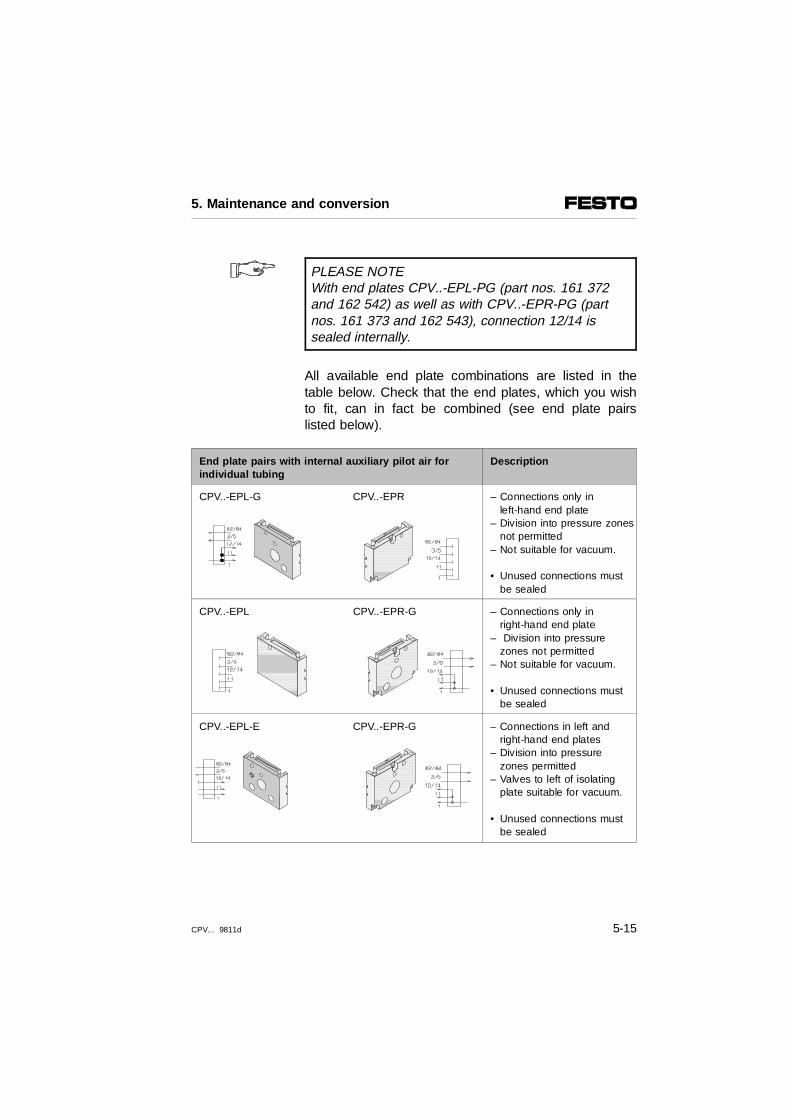
PLEASE NOTEWith end plates CPV..-EPL-PG (part nos. 161 372and 162 542) as well as with CPV..-EPR-PG (partnos. 161 373 and 162 543), connection 12/14 issealed internally.
All available end plate combinations are listed in thetable below. Check that the end plates, which you wishto fit, can in fact be combined (see end plate pairslisted below).
End plate pairs with internal auxiliary pilot air forindividual tubing
Description
CPV..-EPL-G CPV..-EPR – Connections only inleft-hand end plate
– Division into pressure zonesnot permitted
– Not suitable for vacuum.
• Unused connections mustbe sealed
CPV..-EPL CPV..-EPR-G – Connections only inright-hand end plate
– Division into pressurezones not permitted
– Not suitable for vacuum.
• Unused connections mustbe sealed
CPV..-EPL-E CPV..-EPR-G – Connections in left and right-hand end plates
– Division into pressure zones permitted
– Valves to left of isolatingplate suitable for vacuum.
• Unused connections mustbe sealed
5. Maintenance and conversion
CPV... 9811d 5-15

End plate pairs with external auxiliary pilot airfor single tubing
Description
CPV..-EPL-E CPV..-EPR – Connections only in left-hand end plate
– Division into pressurezones not permitted
– Suitable for vacuum
CPV..-EPL CPV..-EPR-E – Connections only in right-hand end plate
– Division into pressurezones not permitted
– Suitable for vacuum
CPV..-EPL-E CPV..-EPR-E – Connections in left andright-hand end plates
– Division into pressurezones permitted
– Suitable for vacuum.• Unused connections
must be sealed.
5. Maintenance and conversion
5-16 CPV... 9811d

End plate pairs with internal auxiliary pilot air and tubing via pneumatic multiple connector plate
Description
CPV..-EPL-PG CPV..-EPR-PG – Connections on thepneumatic multipleconnector plate
– Division into pressurezones only permitted withisolating plate Ident. code T
– Valves to left of isolatingplate suitable for vacuum
– Right end plate withinternal auxiliary pilot air is marked with INT
End plate pairs with external auxiliary pilot air and tubing via pneumatic multiple connector plate
Description
CPV..-EPL-PE CPV..-EPR-PE – Connections on thepneumatic multipleconnector plate
– Division into pressurezones only permitted withisolating plate Ident. code T
– Suitable for vacuum
5. Maintenance and conversion
CPV... 9811d 5-17

Proceed as follows:
•• Loosen the electrical and pneumatic connections(see section "Removing components from valve loca-tions").
•• Loosen the CPV valve terminal from the mountingsurface. Proceed in the reverse sequence to that de-scribed in the sections "Fitting onto a wall", "Fittingonto a hat rail" or "Fitting with feet" in the chapter"Fitting".
•• In the case of CPV valve terminals with CP, AS-i orMP connections, remove the appropriate cover (seesection "Removing components from valve locations").
•• Place the CPV valve terminal on the left-hand endplate. Loosen the outer tie bolts max. 1 turn (see Fig.5/1). You thereby avoid overloading the centre tiebolt.
•• Then loosen the centre tie bolt and remove it.
•• Unscrew the outer tie bolts.
•• Remove the end plate from the CPV valve terminal.Make sure that the other components on the CPVvalve terminal remain together.
•• Place the right-hand end plate on the CPV valve ter-minal and insert the tie bolts.
5. Maintenance and conversion
5-18 CPV... 9811d

•• Place the CPV valve terminal on the right-hand endplate. Make sure that the tie rod, which has not yetbeen tightened, does not fall out of the CPV valveterminal.
•• Remove the left-hand end plate from the CPV valveterminal.
•• Place the left-hand end plate on the CPV valve ter-minal. Swing the CPV valve terminal onto the left-hand end plate.
•• Screw in the tie rod and tighten it with 0.3 Nm.
•• Then tighten first the centre and then the outer tierod with 2 Nm (CPV10/14) or with 4 Nm (CPV18).
•• In the case of CPV valve terminals with CP, AS-i orMP connections, fit the appropriate connector plate(see section "Fitting components onto valve locations").
•• Fit the CPV valve terminals onto their mounting sur-faces (see sections "Fitting onto a wall", "Fitting ontoa hat rail" or "Fitting with feet" in the chapter "Fit-ting").
•• Finally connect the pneumatic tubing and the electri-cal cables (see chapter "Installation").
5. Maintenance and conversion
CPV... 9811d 5-19

5.4 Conversion from individual to central tubing
In order to convert your CPV valve terminal from indi-vidual to central tubing with the pneumatic multiple con-nector plate, you will require the following:
– the pneumatic multiple connector plate
– special end plates for the CPV valve terminal
Proceed as follows:
•• Replace the end plates of the CPV valve terminal asdescribed in the section "Conversion from internal toexternal control air".
•• Fit the pneumatic multiple connector plate as de-scribed in the section "Fitting the pneumatic multipleconnector plate" in chapter 2.
5. Maintenance and conversion
5-20 CPV... 9811d

5.5 Converting the CPV valve terminal to two pressure zones
In order to convert your CPV valve terminal to twopressure zones, you will require an isolating plate (to beordered separately).
Fit the isolating plate as described in the section "Fittingcomponents into the valve locations".
PLEASE NOTE•• When installing the CPV valve terminal, you
must supply compressed air to both sides of the terminal.
•• Seal unused connections (supply and auxiliary pilot air connections) with blind plugs.
5. Maintenance and conversion
CPV... 9811d 5-21

5.6 Converting the CPV valve terminal to different electricalconnections
Due to the modular structure of the CPV valve terminal,you can convert it to IC, MP, AS-i or CP connections.
PLEASE NOTEWith this conversion you should observe:– the instructions for fitting the CPV valve terminal
with "F valve plates" (Ident. Code F). See section"Valve plates" under "Description of components" in the chapter "System summary."
– that only a CPV valve terminal with a CP connection may be fitted with relay plates.
Proceed as follows:
CPV valve terminals with IC connection
•• Loosen the locking screws on the connectingsockets.
•• Pull the socket carefully away from the connectinglugs on the pilot solenoid coil.
•• Insert the MP, AS-i or CP connection onto the con-necting lugs of the pilot solenoid coils.
•• Fasten the connector plate with the 4 socket headscrews. Tighten the screws in a diagonally oppositesequence.
5. Maintenance and conversion
5-22 CPV... 9811d

CPV valve terminals with MP, AS-i or CP connection
•• Loosen the 4 socket head screws of the connector plate.
•• Pull the connector plate carefully away from the con-necting lugs of the pilot solenoid coils.
MP, AS-i or CP connector plate
•• Insert the connector plate onto the connecting lugs ofthe pilot solenoid coils.
•• Fasten the connector plate with the 4 socket headscrews.
•• Tighten the screws in a diagonally opposite se-quence.
IC connections
•• In the case of "F valve plates" (Ident. code F), insertthe intermediate plugs for current reduction onto theconnecting lugs of the pilot solenoid coils.
•• Insert the connector sockets onto the connecting lugsof the pilot solenoid coils. Make sure that the guidebolts grip into the connector socket.
•• Fasten the socket with the central locking screw.
5. Maintenance and conversion
CPV... 9811d 5-23

5. Maintenance and conversion
5-24 CPV... 9811d

Appendix A
Technical appendix
A. Technical appendix
CPV... 9811d A-1

Contents
Technical appendix
A.1 Accessories. . . . . . . . . . . . . . . . . . . . . . . . . . . . . . . . . . . . . . . . . A-3A.2 Technical specifications . . . . . . . . . . . . . . . . . . . . . . . . . . . . . . . A-4A.3 Index . . . . . . . . . . . . . . . . . . . . . . . . . . . . . . . . . . . . . . . . . . . . . . A-9
A. Technical appendix
A-2 CPV... 9811d

A.1 Accessories
General
CPV10/14 CPV18
Hat-rail mounting kitWall mounting kit (rear)Wall mounting kit (front)Identifier clipManual override cover
CPV10/14-VI-BG-NRH-35CPV10/14-VI-BG-RWLCPV..-VI-BG-ER200XIBS6x10CPV..-VI-BZ-T...
CPV18-VI-BG-NRH-35CPV18-VI-BG-RW
IBS9x20CPV18-VI-BZ-T...
CPV valve terminal with AS-i connectionAS-i combi power unitAS-i bus cable (yellow)AS-i additional supply cable (black)Sensor cableAS-i cable capAS-i cable sleeve
ASI-CNT-115/230 V ACASI-1,5-Y-100ASI-1,5-Z-100KM8-M8-GSGDASI-FK-KKASI-KT-FK
CPV valve terminal with CP connectionCP cable
Relay cable
KVI-CP-1...KVI-CP-2... (for drag chain use)KRP-1-24...
CPV valve terminal with IC connectionIndividual plug KMYZ-3-24-...-LED,
KMYZ-5-24-...-LEDKMYZ-4-24-... (without LED, complies with IP 40)
CPV valve terminal withMP connectionReady-to-use multipin cableMultipin socket
KMP3-...P-...-XSD-SUB-D-BU
A. Technical appendix
CPV... 9811d A-3

A.2 Technical specifications
General
Permitted temperature range: – storage– operation– medium
- 20 to + 40 oC- 5 to + 50 oC- 5 to + 50 oC
Protection class as per EN 60 529 IP 65 (with FESTO accessories cable)
Relative humidity 90 % at 20 oC or 40 % at 50 oC
Corrosion protection (as per FN940070) KBK 2
Fitting position As desired
Tightening torques CPV10/14 CPV18
– Socket for IC connection– Connecting socket for relay
outputs – Fastening screw for wall support
or hat rail – Screws for fastening CPV valve termi-nal
to pneumatic multipin – Electrical connector plate– Earth connection– Tie rod
0.15 Nm
0.15 Nm
1.5 Nm
2.0 Nm0.7 Nm1.0 Nm1st. stage 0.3 Nm2nd. stage 2.0 Nm
4.0 Nm
4.0 Nm3.0 Nm1.0 Nm1st. stage 0.3 Nm2nd. stage 4.0 Nm
MaterialsPlates, cover, pneumatic multipleconnector plate:Seal:
AL, AL-GD, Ms, PAXMD6, PET, POM, PPS, ST,NBR, HNBR
Oscillation(as per DIN/IEC 68 part 2–6)– Transport:
– Operation/use:
Shock:(as per DIN/IEC 68 part 2–27)
3.5 mm travel at 2–9 Hz1 g acceleration at 9–200 Hz
0.35 mm travel at 10–60 Hz5 g acceleration at 60–150 Hz
30 g acceleration at 11 ms duration
A. Technical appendix
A-4 CPV... 9811d

General
Approximate weights (in kg) CPV10 CPV14 CPV18
Electrical connector plate with AS-i connection- on CPV valve terminals with 2 valve locations- on CPV valve terminals with 4 valve locations
0.0850.110
0.1300.175
0.2750.355
Electrical connector plate with CP connection- on CPV valve terminals with 4 valve locations- on CPV valve terminals with 6 valve locations- on CPV valve terminals with 8 valve locations
0.1450.1800.200
0.2300.2500.300
0.3750.4500.540
Electrical connector plate with MP connection- on CPV valve terminals with 4 valve locations- on CPV valve terminals with 6 valve locations- on CPV valve terminals with 8 valve locations
0.1100.1400.165
0.1700.2300.275
0.4000.4250.515
End plates 0.160 0.280 0.740
Pneumatic multiple connector plate- on CPV valve terminals with 2 valve locations- on CPV valve terminals with 4 valve locations- on CPV valve terminals with 6 valve locations- on CPV valve terminals with 8 valve locations
0.1200.1650.2250.270
0.2700.3900.5100.630
0.5200.7500.8701.300
Relay plate 0.035 0.055 -----
Reserve plate 0.025 0.045 0.090
Isolating plate 0.025 0.045 0.090
Valve plates 0.65 0.110 0.260
A. Technical appendix
CPV... 9811d A-5

CAUTIONOperate the CPV valve terminal only with the medium described below.– If possible use non-lubricated auxiliary pilot air
(connection 12/14). Otherwise use hydraulic oiltype DIN 51524-HL32/ISO 6743-4. The oil
content must not exceed 3 drops per 1000 l of air consumed. This corresponds to 1 drop/4 minutes at 6 bar supply pressure and with medium flow.Observe the specifications on special oil for maintenance units in the Festo Pneumatics Catalogue.
– In the case of CPV valve terminals with internallybranched auxiliary pilot air the above mentionedinstruction also applies to the supply air (connection 1/11).
Pneumatic components
Medium Compressed air, filtered (40 µm), lubricated(Oil: VG 32) or non-lubricated/vacuum
Design Valve plates with spool valves
Pressure range CPV10/14 CPV18
– with internal auxiliary pilot air takenfrom 1 or 11
– with externally supplied auxiliary pilot air
– 12/14
3-8 bar
- 0.9-10 bar
3-8 bar
3-8 bar
- 0.9-10 bar
3.5-8 bar (ident. code G)2-8 bar (ident. code J)3-8 bar (all other valves),
Manual override pushing or locking
A. Technical appendix
A-6 CPV... 9811d

PLEASE NOTEThe flow rates of the valves are reduced by thescrew couplings of the pneumatic connections.
Pneumatik
Rated flow CPV10 CPV14 CPV18
(without screw connectors) in [l/min] microvalves (CPV10),mini valves (CPV14) andmidi valves (CPV18)
of 11 ⇒ 2 or 1 ⇒ 4
of 2 ⇒ 3/5 or 4 ⇒ 3/5
400
400
800
800
16001400
(5/3-valve)1600
Valve switching times in ms CPC10 CPV14 CPV18
Measuring method 10 % , as per FN 942032 onswitch
off onswitch
off onswitch
off
2/2-way valve closed (Ident.code D)
3/2-way valve open or closed(Ident. code C, H, N)5/2-way single solenoid valve (Ident. code M) 5/2-way single solenoid valve (Ident. code F) 5/2-way double solenoid valve (Ident. code J) 5/3-way valve, mid-position blocked (Ident. code G)
15
17
171310
...
17 (at0%)25
2717...
---
13
24
25...12
...
16 (at0%)30
35......
...
14
18
18.5...12
14
20 (at0%)24
26......
32
Connections CPV10 CPV14 CPV18
(Values in brackets for pneum. multiple connector plate)– compressed air (1;11)– exhaust (3/5)– auxiliary pilot air (12; 14; 82/84)– work air (2; 4)
G 1/8G 3/8 (G 1/4)
M 5 (M 7)M 7
G 1/4G 1/2 (G 3/8)G 1/8 (G 1/8)
G 1/8
G 3/8G 1/2G 1/4G 1/4
A. Technical appendix
CPV... 9811d A-7

Electrical components (CPV valve terminal with individual or CP connection)
Electromagnetic compatibi lity of the CPV valve terminal with CP connection
Interference emission:Resistance to interference
Tested as per EN 55011, limit value class BTested as per EN 50082–2
Protection against electric shock (protection against direct and indirect contact as per EN 60204-1/IEC 204)
By means of PELV power units (protected extra low voltage)
Relay plate Consisting of 2 relays for controlling 2electrically isolated outputs
Operating voltageTolerance:– CPV valve terminal with CP connection– CPV valve terminal with IC connection
24 V DC
20.4–26.4 V18.0–26.4 V
Power consumption at 21 V Values in brackets for 24 V
CPV10 CPV14 CPV18
CPV valve terminal all connection variants:– per solenoid coilvalve
CPV valve terminal with CP connection:– per relay plate CPV valve terminal with IC connection: – additional per individual connector plug
0.46 W(0,6 W)
(1.2 W)
≤ 0.26 W
0.65 W(0,85 W)
(1.2 W)
≤ 0.26 W
1.16 W(1.5 W)
---------
≤ 0.26 W
Input current consumption ofelectronic components:CPV valve terminal with CP connection
20 mA 25 mA
Load circuit data for relay outputs(at 24 V + 10%)
1 A ; Contacts floating
Switching times of the relay outputs (with normal voltage) – pickup time – drop-off tiime
5 ms2 ms
PLEASE NOTEData on the electrical components of the CPV valveterminal with multipin or AS-i connection is suppliedwith the relevant product.
A. Technical appendix
A-8 CPV... 9811d

A.3 Index
AAbbreviations . . . . . . . . . . . . . . . . . . . . . . . . . . . . . . . . XIAuxiliary pilot air
external . . . . . . . . . . . . . . . . . . . . . . . . . . . . . . . . 3-7internal . . . . . . . . . . . . . . . . . . . . . . . . . . . . . . . . . 3-6
CCommon pneumatic tubing . . . . . . . . . . . . . . . . . . . . 3-9Connection sizes of pneum. screw connectors. . . . . 3-8Connections
electrical (valve terminal with AS-i connection). 1-16electrical (valve terminal with CP connection). . 1-15electrical (valve terminal with IC connection) . . 1-13electrical (valve terminal with MP connection) . 1-14pneumatic . . . . . . . . . . . . . . . . . . . . . . . . . . . . . 1-12
Conversionmanual override . . . . . . . . . . . . . . . . . . . . . . . . . 5-13
CPV valve terminalcomponents . . . . . . . . . . . . . . . . . . . . . . . . . . . . . 1-8earthing the CPV valve terminal . . . . . . . . . . . . 3-12sizes. . . . . . . . . . . . . . . . . . . . . . . . . . . . . . . . . . . 1-6summary of variants . . . . . . . . . . . . . . . . . . . . . . 1-4valve plates . . . . . . . . . . . . . . . . . . . . . . . . . . . . . . X
A. Technical appendix
CPV... 9811d A-9

DDanger categories . . . . . . . . . . . . . . . . . . . . . . . . . . . . VIDesignated use . . . . . . . . . . . . . . . . . . . . . . . . . . . . . . VDesignation clips . . . . . . . . . . . . . . . . . . . . . . . . . . . 2-22Display elements
CPV valve terminal with AS-i connection . . . . . 1-16CPV valve terminal with CP connection . . . . . . 1-15CPV valve terminal with IC connection . . . . . . . 1-13CPV valve terminal with MP connection . . . . . . 1-14
EEarthing the CPV valve terminal . . . . . . . . . . . . . . . 3-12Electromagnetic compatibility (EMC) . . . . . . . . . . . . A-8EMERGENCY STOP . . . . . . . . . . . . . . . . . . . . . . . . 4-11End plate identification . . . . . . . . . . . . . . . . . . . . . . . . 3-6End plate pairs . . . . . . . . . . . . . . . . . . . . . . . . . . . . . 5-14
FFastening accessories
fastening profile sections for fitting onto a wall . . 2-5hat rail . . . . . . . . . . . . . . . . . . . . . . . . . . . . . . . . . 2-9
Fitting kitfor fitting onto a hat rail . . . . . . . . . . . . . . . . . . . . 2-8for fitting onto a wall. . . . . . . . . . . . . . . . . . . . . . . 2-4
Fitting variants . . . . . . . . . . . . . . . . . . . . . . . . . . . . . . 2-3Functional impairments . . . . . . . . . . . . . . . . . . . . . . 4-10
HHat rail . . . . . . . . . . . . . . . . . . . . . . . . . . . . . . . . . . . . 2-8Hat rail clamping unit . . . . . . . . . . . . . . . . . . . . . . . . 2-10
A. Technical appendix
A-10 CPV... 9811d

IIdentification code . . . . . . . . . . . . . . . . . . . . . . . . . . . 1-9Information on this manual . . . . . . . . . . . . . . . . . . . . VIII
LLED display of valves . . . . . . . . . . . . . . . . . . . . . . . 4-12Low pressure operation . . . . . . . . . . . . . . . . . 3-10, 4-11
MManual override
conversion . . . . . . . . . . . . . . . . . . . . . . . . . . . . . 5-13designs. . . . . . . . . . . . . . . . . . . . . . . . . . . . . . . . . 4-6
Micro valves . . . . . . . . . . . . . . . . . . . . . . . . . . . . . . . . 1-6Midi valves . . . . . . . . . . . . . . . . . . . . . . . . . . . . . . . . . 1-6Mini valves . . . . . . . . . . . . . . . . . . . . . . . . . . . . . . . . . 1-6
OOperating status. . . . . . . . . . . . . . . . . . . . . . . . . . . . 4-11Operating voltage. . . . . . . . . . . . . . . . . . . . . . . . . . . . A-8
PPictograms . . . . . . . . . . . . . . . . . . . . . . . . . . . . . . . . . VIIPneumatic multipin. . . . . . . . . . . . . . . . . . . . . . . . . . 2-21Pneumatic operating status . . . . . . . . . . . . . . . . . . . 4-11Position of LEDs . . . . . . . . . . . . . . . . . . . . . . . . . . . 4-13Power consumtion . . . . . . . . . . . . . . . . . . . . . . . . . . . A-8Pressure ranges. . . . . . . . . . . . . . . . . . . . . . . . . . . . . A-6Pressure zones . . . . . . . . . . . . . . . . . . . . 3-7, 3-10, 4-11Protective cover of manual override . . . . . . . . . . . . 2-22
A. Technical appendix
CPV... 9811d A-11

RRated flows . . . . . . . . . . . . . . . . . . . . . . . . . . . . . . . A-7Relay outputs . . . . . . . . . . . . . . . . . . . . . . . . . . . . . . 3-13Relay plate . . . . . . . . . . . . . . . . . XII, 1-6, 1-8 - 1-9, 1-15
SSupply pressure
with external auxiliary pilot air . . . . . . . . . . . . . . . 3-7with internal auxiliary pilot air. . . . . . . . . . . . . . . . 3-6
Support rail . . . . . . . . . . . . . . . . . . . . . . . . . . . . . . . . . 2-8Switch-on pressurization . . . . . . . . . . . . . . . . . . . . . . 4-7Switching status display. . . . . . . . . . . . . . . . . . . . . . 4-14
TTarget group . . . . . . . . . . . . . . . . . . . . . . . . . . . . . . . . . VText markings . . . . . . . . . . . . . . . . . . . . . . . . . . . . . . . VIITightening torques . . . . . . . . . . . . . . . . . . . . . . . . . A-4Tubing variants. . . . . . . . . . . . . . . . . . . . . . . . . . . . . . 3-4
UUser instructions . . . . . . . . . . . . . . . . . . . . . . . . . . . . . VI
VVacuum operation . . . . . . . . . . . . . . . . . . . . . . . . . . 4-11Valve plates . . . . . . . . . . . . . . . . . . . . . . . . . . . . . X, 1-9
identification code . . . . . . . . . . . . . . . . . . . . . . . . 1-9Valve switching times . . . . . . . . . . . . . . . . . . . . . . . . A-7Valve test . . . . . . . . . . . . . . . . . . . . . . . . . . . . . . . . . . 4-8
A. Technical appendix
A-12 CPV... 9811d