Embed Size (px)
Citation preview
1COMP381 by M. Hamdi
Input/Output Input/Output SystemsSystems
2COMP381 by M. Hamdi
Motivation: Who Cares About I/O?
• CPU Performance: 60% per year
• I/O system performance limited by mechanical delays (disk I/O)
< 10% per year (IO per sec)
• 10% IO & 10x CPU => 5x Performance (lose 50%)
10% IO & 100x CPU => 10x Performance (lose 90%)
• I/O bottleneck:
Diminishing value of faster CPUs
3COMP381 by M. Hamdi
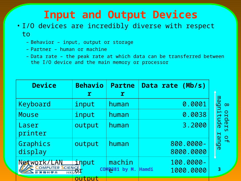
Input and Output Devices• I/O devices are incredibly diverse with respect to
– Behavior – input, output or storage
– Partner – human or machine
– Data rate – the peak rate at which data can be transferred between the I/O device and the main memory or processor
Device Behavior Partner Data rate (Mb/s)
Keyboard input human 0.0001
Mouse input human 0.0038
Laser printer output human 3.2000
Graphics display output human 800.0000-8000.0000
Network/LAN input or output
machine 100.0000-1000.0000
Magnetic disk storage machine 240.0000-2560.0000
8 orders of magnitude
range
4COMP381 by M. Hamdi
I/O Performance Measures
• I/O bandwidth (throughput) – amount of information that can be input (output) and communicated across an interconnect (e.g., a bus) to the processor/memory (I/O device) per unit time
1. How much data can we move through the system in a certain time?
2. How many I/O operations can we do per unit time?
• I/O response time (latency) – the total elapsed time to accomplish an input or output operation– An especially important performance metric in real-time systems
• Many applications require both high throughput and short response times
5COMP381 by M. Hamdi
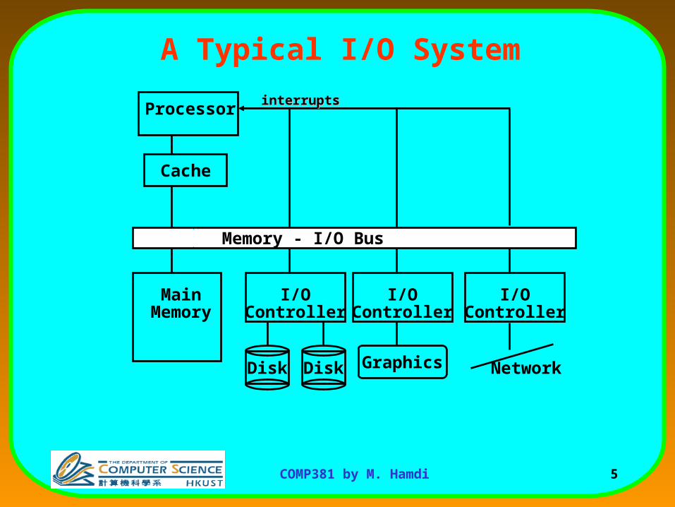
A Typical I/O System
Processor
Cache
Memory - I/O Bus
MainMemory
I/OController
Disk Disk
I/OController
I/OController
Graphics Network
interruptsinterrupts
6COMP381 by M. Hamdi
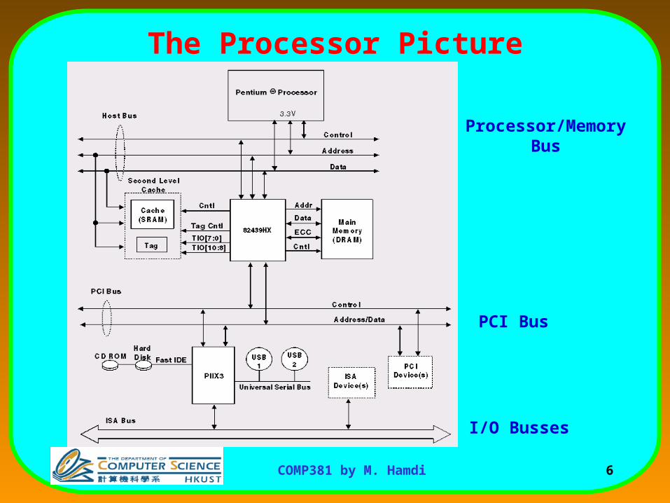
The Processor Picture
Processor/MemoryBus
PCI Bus
I/O Busses
7COMP381 by M. Hamdi
Introduction to I/O• I/O devices are very slow compared to the cycle time of a CPU.
• Much like memory, the architecture of I/O systems is an active area of research.– I/O systems can define the success of a system.
• Computer architects strive to design systems that do not tie up the CPU waiting for slow I/O systems (too many applications running simultaneously on processor).
• Importance of IO: People care more about storing information and communicating information than calculating– "Information Technology" vs. "Computer Science"
– 1960s and 1980s: Computing Revolution
– 1990s and 2000s: Information Age
8COMP381 by M. Hamdi
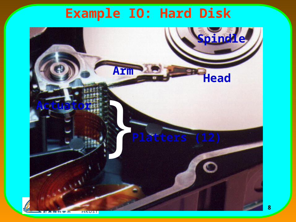
Example IO: Hard Disk
Actuator
ArmHead
Platters (12)
{Spindle
9COMP381 by M. Hamdi
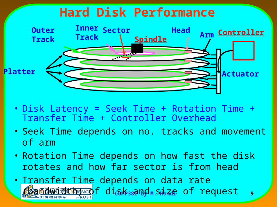
Hard Disk Performance
Platter
Arm
Actuator
HeadSectorInnerTrack
OuterTrack
• Disk Latency = Seek Time + Rotation Time + Transfer Time + Controller Overhead
• Seek Time depends on no. tracks and movement of arm
• Rotation Time depends on how fast the disk rotates and how far sector is from head
• Transfer Time depends on data rate (bandwidth) of disk and size of request
ControllerSpindle
10COMP381 by M. Hamdi
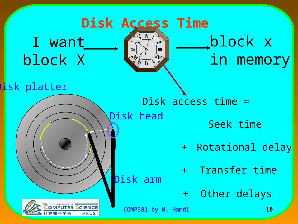
Disk Access Time
+ Rotational delay
+ Transfer time
Seek time
Disk access time =
+ Other delays
Disk platter
Disk arm
Disk head
block xin memory
I wantblock X
11COMP381 by M. Hamdi
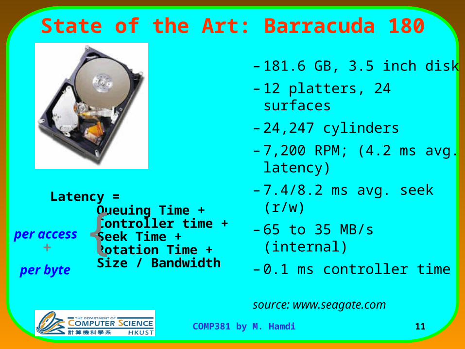
State of the Art: Barracuda 180
– 181.6 GB, 3.5 inch disk
– 12 platters, 24 surfaces
– 24,247 cylinders
– 7,200 RPM; (4.2 ms avg. latency)
– 7.4/8.2 ms avg. seek (r/w)
– 65 to 35 MB/s (internal)
– 0.1 ms controller time
source: www.seagate.com
Latency = Queuing Time + Controller time +Seek Time + Rotation Time + Size / Bandwidth
per access
per byte
{+
12COMP381 by M. Hamdi
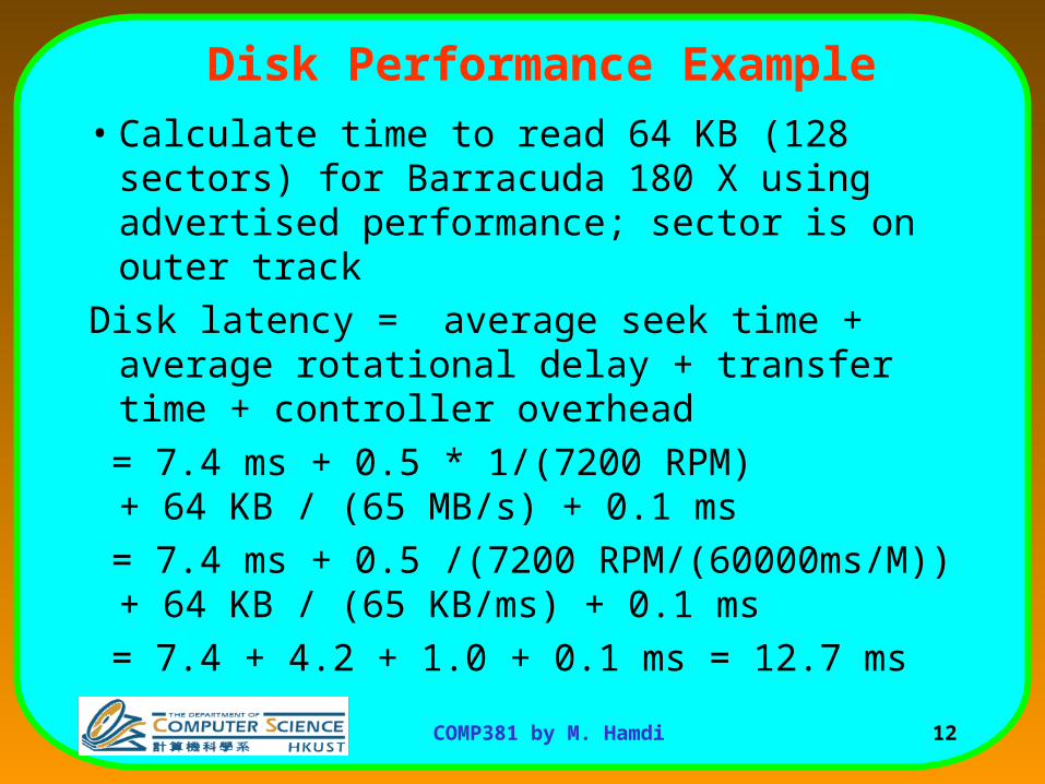
Disk Performance Example
• Calculate time to read 64 KB (128 sectors) for Barracuda 180 X using advertised performance; sector is on outer track
Disk latency = average seek time + average rotational delay + transfer time + controller overhead
= 7.4 ms + 0.5 * 1/(7200 RPM) + 64 KB / (65 MB/s) + 0.1 ms
= 7.4 ms + 0.5 /(7200 RPM/(60000ms/M)) + 64 KB / (65 KB/ms) + 0.1 ms
= 7.4 + 4.2 + 1.0 + 0.1 ms = 12.7 ms
13COMP381 by M. Hamdi
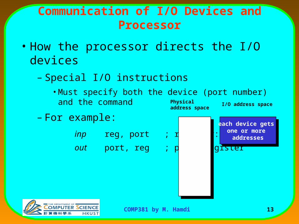
Communication of I/O Devices and Processor
• How the processor directs the I/O devices– Special I/O instructions
• Must specify both the device (port number) and the command
– For example:
inp reg, port ; register:=port
out port, reg ; port:=register
Physical address space
each device gets one or more
addresses
each device gets one or more
addresses
I/O address space
14COMP381 by M. Hamdi
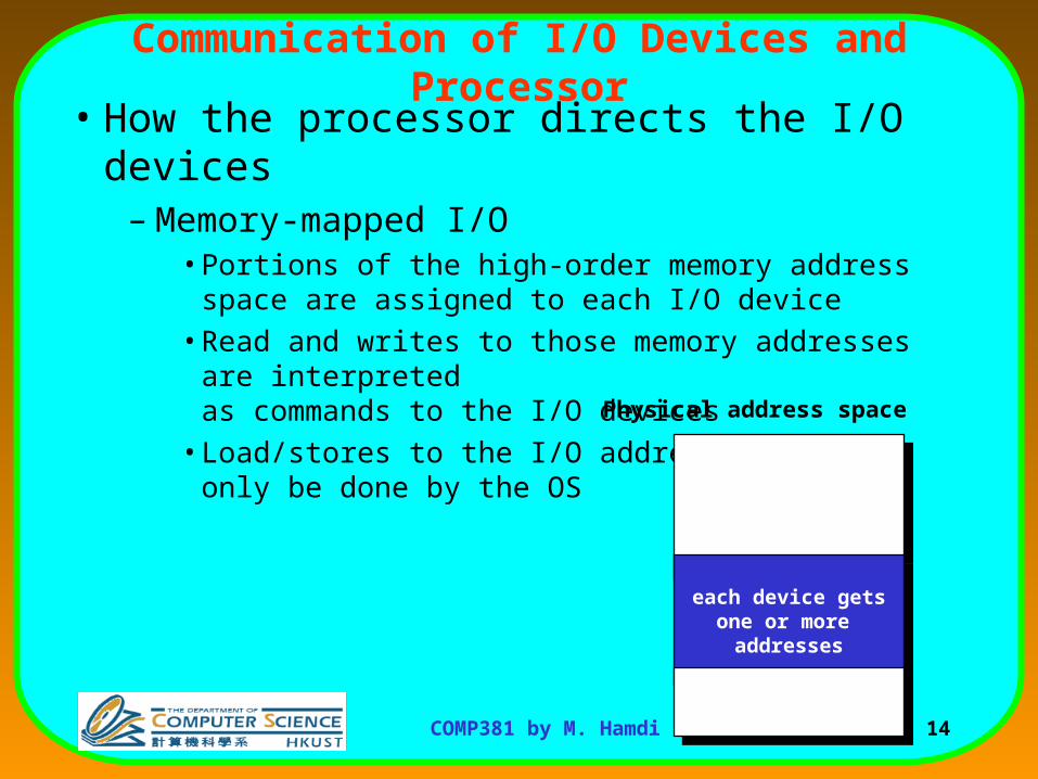
Communication of I/O Devices and Processor• How the processor directs the I/O devices
– Memory-mapped I/O• Portions of the high-order memory address space are assigned to
each I/O device
• Read and writes to those memory addresses are interpretedas commands to the I/O devices
• Load/stores to the I/O address space can only be done by the OS
each device getsone or more
addresses
each device getsone or more
addresses
Physical address space
15COMP381 by M. Hamdi
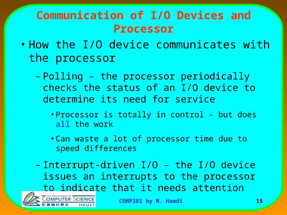
Communication of I/O Devices and Processor
• How the I/O device communicates with the processor
– Polling – the processor periodically checks the status of an I/O device to determine its need for service
• Processor is totally in control – but does all the work
• Can waste a lot of processor time due to speed differences
– Interrupt-driven I/O – the I/O device issues an interrupts to the processor to indicate that it needs attention
16COMP381 by M. Hamdi
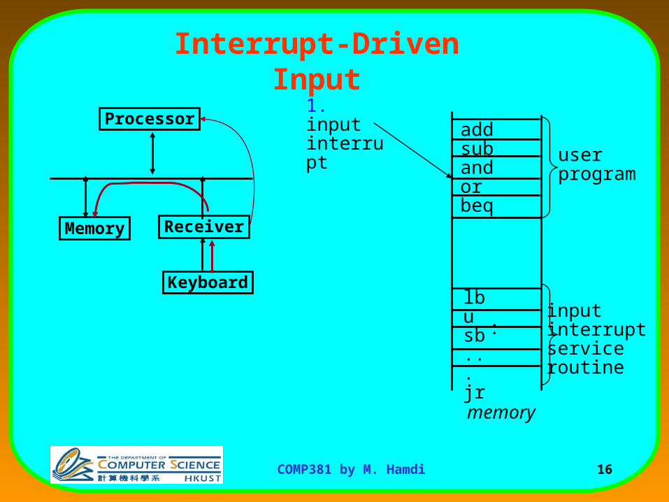
Interrupt-Driven Input
addsubandorbeq
lbusb...jr
memory
userprogram
1. input interrupt
inputinterruptserviceroutine
Processor
ReceiverMemory
:
Keyboard
17COMP381 by M. Hamdi
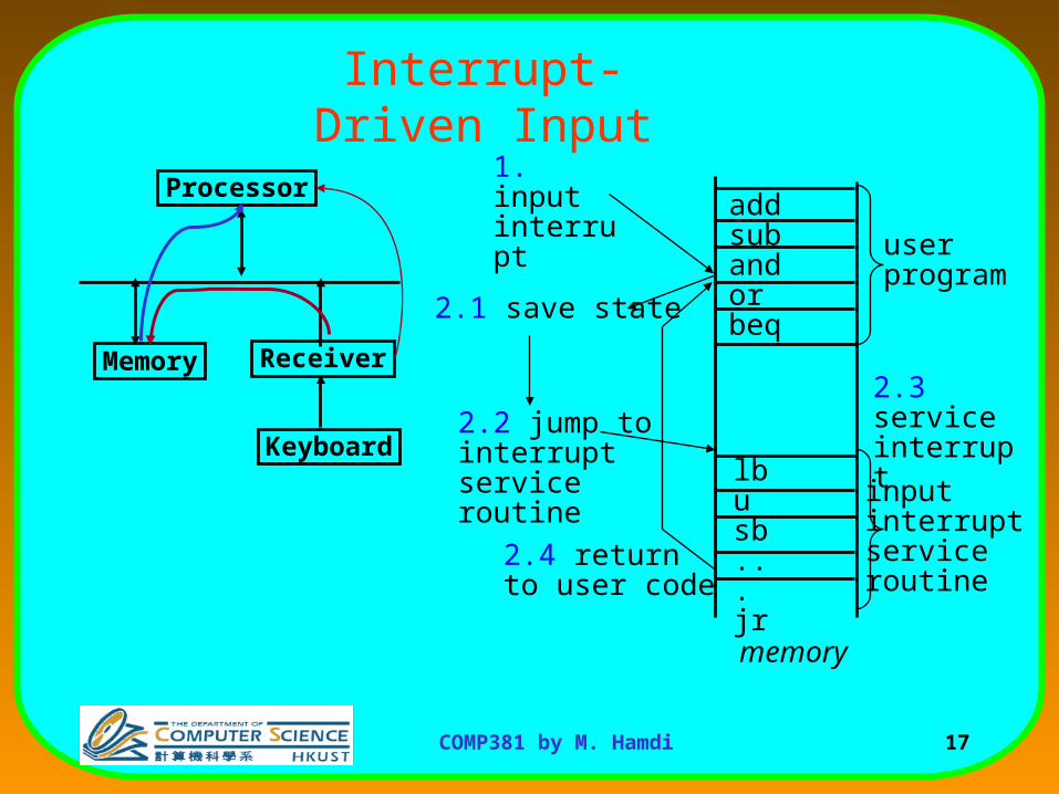
Interrupt-Driven Input
memory
userprogram
1. input interrupt
2.1 save state
Processor
ReceiverMemory
addsubandorbeq
lbusb...jr
2.2 jump to interruptservice routine
2.4 returnto user code
Keyboard
2.3 service interrupt
inputinterruptserviceroutine
18COMP381 by M. Hamdi
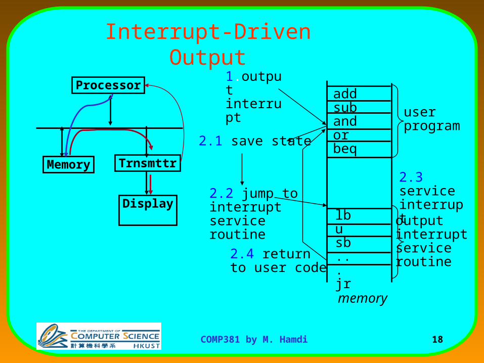
Interrupt-Driven Output
Processor
TrnsmttrMemory
Display
addsubandorbeq
lbusb...jr
memory
userprogram
1.output interrupt
2.1 save state
outputinterruptserviceroutine
2.2 jump to interruptservice routine
2.4 returnto user code
2.3 service interrupt
19COMP381 by M. Hamdi
Direct-Memory Access (DMA)
• Interrupt-driven IO relieves the CPU from waiting for every IO event
• But the CPU can still be bugged down if it is used in transferring IO data.
– Typically blocks of bytes.
• For high-bandwidth devices (like disks) interrupt-driven I/O would consume a lot of processor cycles
20COMP381 by M. Hamdi
DMA
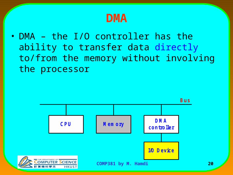
• DMA – the I/O controller has the ability to transfer data directly to/from the memory without involving the processor
CPU MemoryDMA
controller
I/O Device
Bus
21COMP381 by M. Hamdi
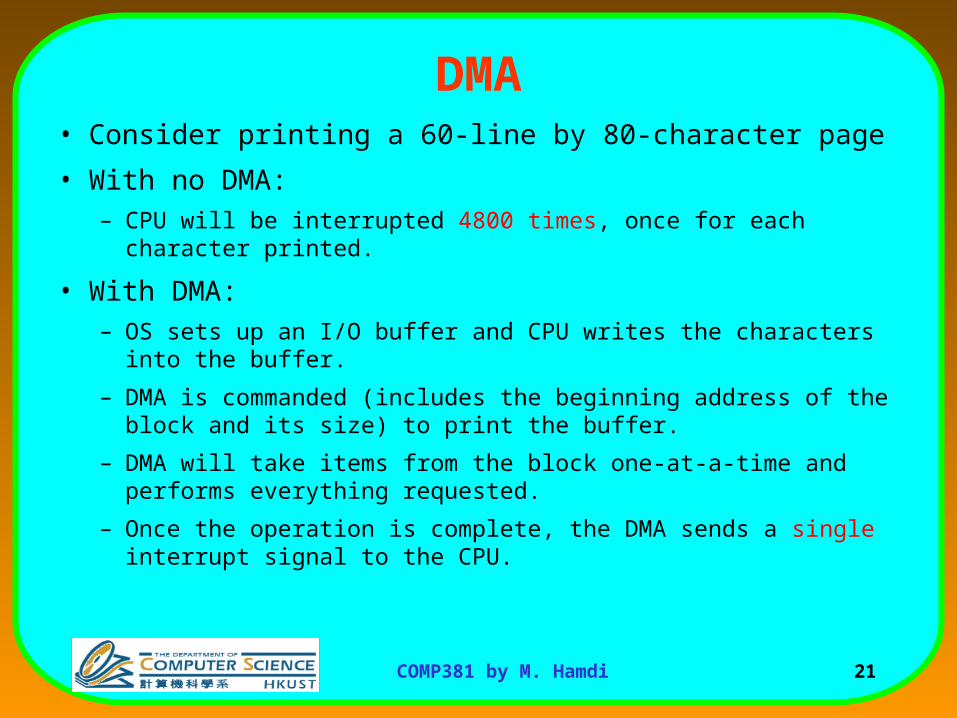
DMA• Consider printing a 60-line by 80-character page
• With no DMA:– CPU will be interrupted 4800 times, once for each character printed.
• With DMA:– OS sets up an I/O buffer and CPU writes the characters into the buffer.
– DMA is commanded (includes the beginning address of the block and its size) to print the buffer.
– DMA will take items from the block one-at-a-time and performs everything requested.
– Once the operation is complete, the DMA sends a single interrupt signal to the CPU.
22COMP381 by M. Hamdi
I/O Communication Protocols
• Typically one I/O channel controls multiple I/O devices.
• We need a two-way communication between the channel and the I/O devices.– The channel needs to send the command/data to the I/O
devices.
– The I/O devices need to send the data/status information to the channel whenever they are ready.
23COMP381 by M. Hamdi
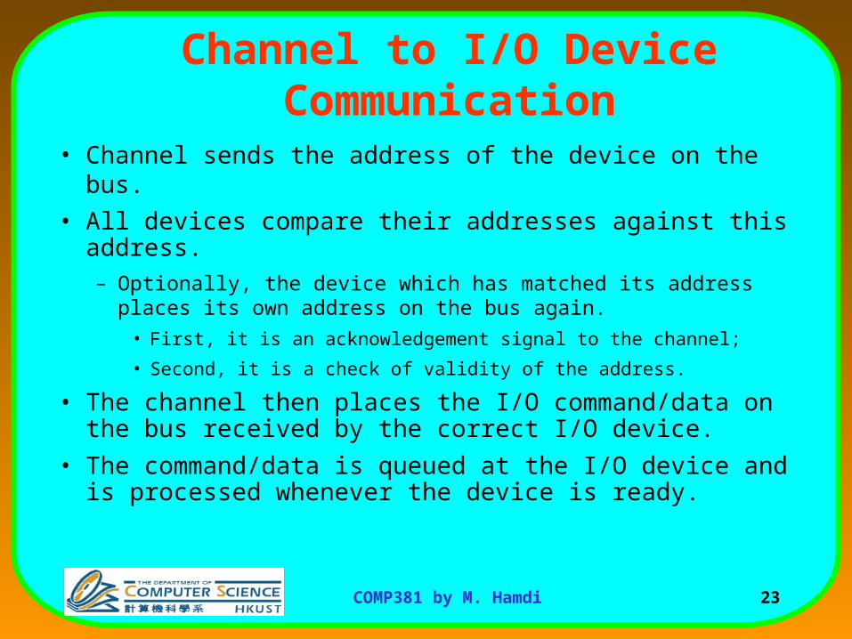
Channel to I/O Device Communication
• Channel sends the address of the device on the bus.
• All devices compare their addresses against this address.– Optionally, the device which has matched its address places its own
address on the bus again.
• First, it is an acknowledgement signal to the channel;
• Second, it is a check of validity of the address.
• The channel then places the I/O command/data on the bus received by the correct I/O device.
• The command/data is queued at the I/O device and is processed whenever the device is ready.
24COMP381 by M. Hamdi
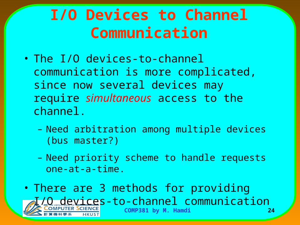
I/O Devices to Channel Communication
• The I/O devices-to-channel communication is more complicated, since now several devices may require simultaneous access to the channel.
– Need arbitration among multiple devices (bus master?)
– Need priority scheme to handle requests one-at-a-time.
• There are 3 methods for providing I/O devices-to-channel communication
25COMP381 by M. Hamdi
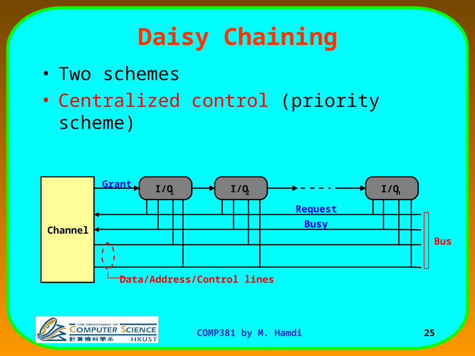
Daisy Chaining
• Two schemes• Centralized control (priority scheme)
Channel
I/O1 I/O2 I/On
Bus
Data/Address/Control lines
Grant
Request
Busy
26COMP381 by M. Hamdi
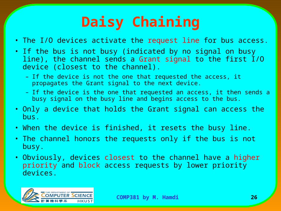
Daisy Chaining• The I/O devices activate the request line for bus access.
• If the bus is not busy (indicated by no signal on busy line), the channel sends a Grant signal to the first I/O device (closest to the channel).– If the device is not the one that requested the access, it propagates the
Grant signal to the next device.
– If the device is the one that requested an access, it then sends a busy signal on the busy line and begins access to the bus.
• Only a device that holds the Grant signal can access the bus.
• When the device is finished, it resets the busy line.
• The channel honors the requests only if the bus is not busy.
• Obviously, devices closest to the channel have a higher priority and block access requests by lower priority devices.
27COMP381 by M. Hamdi
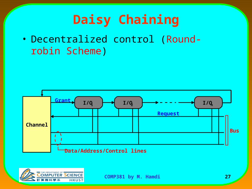
Daisy Chaining
• Decentralized control (Round-robin Scheme)
Channel
I/O1 I/O2 I/On
Bus
Data/Address/Control lines
Grant
Request
28COMP381 by M. Hamdi
Daisy Chaining• The I/O devices send their request.
• The channel activates the Grant line.
• The first I/O device which requested access accepts the Grant signal and has control over the bus.– Only the devices that have received the grant signal can have access to
the bus.
• When a device is finished with an access, it checks to see if the request line is activated or not.
• If it is activated, the current device sends the Grant signal to the next I/O device (Round-Robin) and the process continues.– Otherwise, the Grant signal is deactivated.
29COMP381 by M. Hamdi
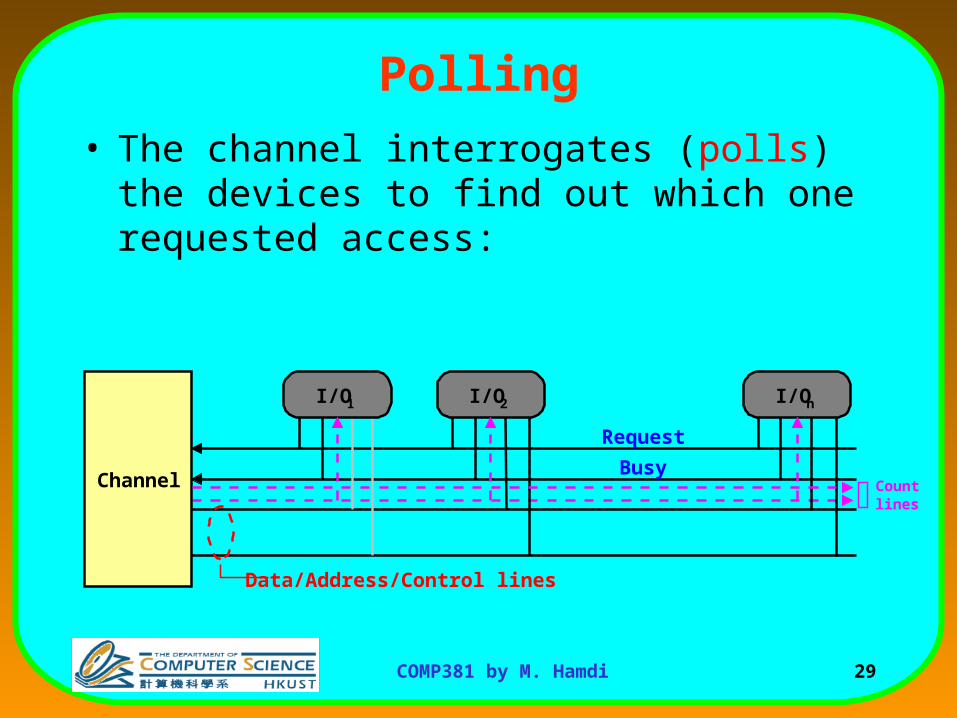
Polling
• The channel interrogates (polls) the devices to find out which one requested access:
Channel
I/O1 I/O2 I/On
Countlines
Data/Address/Control lines
Request
Busy
30COMP381 by M. Hamdi
Polling
• Any device requesting access places a signal on request line.
• If the busy signal is off, the channel begins polling the devices to see which one is requesting access.– It does this by sequentially sending a count from 1 to n on log2n lines to the
devices.
• Whenever a requesting device matches the count against its own number (address), it activates the busy line.
• The channel stops the count (polling) and the device has access over the bus.
• When access is over, the busy line is deactivated and the channel can either continue the count from the last device (Round-Robin) or start from the beginning (priority).
31COMP381 by M. Hamdi
Independent Requests
Channel
I/O 1 I/O 2 I/O n
Bus
Data/Address/Control lines
Grant
Request
Grant
Request
32COMP381 by M. Hamdi
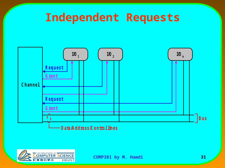
Independent Requests
• Each device has its own Request-Grant lines:– Again, a device sends in its request, the channel
responds by granting access
– Only the device that holds the grant signal can access the bus
– When a device finishes access, it lowers it request signal.
– The channel can use either a Priority scheme or Round-Robin scheme to grant the access.
33COMP381 by M. Hamdi
I/O Buses
• Connect I/O devices (channels) to memory.– Many types of devices are connected to a bus.
– Have a wide range of bandwidth requirements for the devices connected to a bus.
– Typically follow a bus standard, e.g., PCI, SCSI.
• Clocking schemes:– Synchronous: The bus includes a clock signal in the
control lines and a fixed protocol for address and data relative to the clock.
34COMP381 by M. Hamdi
I/O Buses
C lock
Address
D ata
R ead
W ait
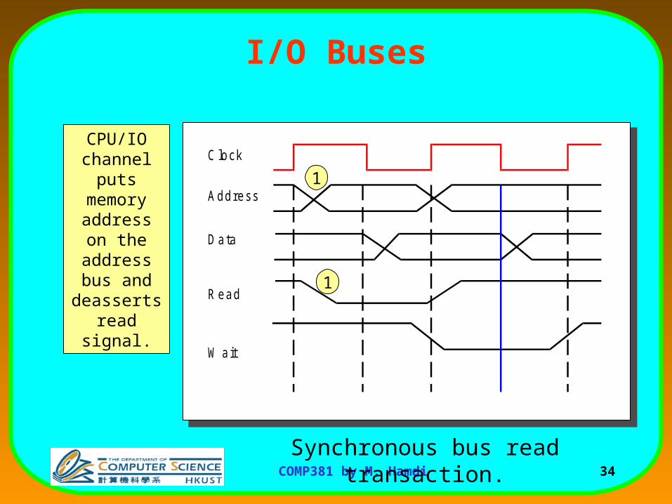
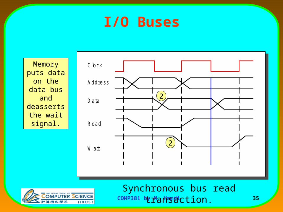
Synchronous bus read transaction.
1
1
CPU/IO channel puts
memory address on the address
bus and deasserts
read signal.
35COMP381 by M. Hamdi
I/O Buses
C lock
Address
D ata
R ead
W ait
Synchronous bus read transaction.
2
2
Memory puts data on the
data bus and deasserts the wait signal.
36COMP381 by M. Hamdi
I/O Buses
C lock
Address
D ata
R ead
W ait
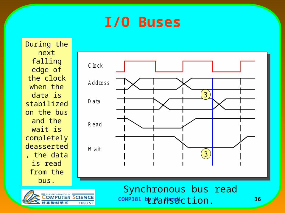
Synchronous bus read transaction.
3
3
During the next falling edge of the clock when
the data is stabilized on
the bus and the wait is
completely deasserted, the
data is read from the bus.
37COMP381 by M. Hamdi
I/O Buses
• Synchronous buses are fast and inexpensive, but– All devices on the bus must run at the same clock rate.
– Due to clock-skew problems, buses cannot be long.
– CPU-Memory buses are typically implemented as synchronous buses.
• The front side bus (FSB) clock rate typically determines the clock speed of the memory you must install.
38COMP381 by M. Hamdi
I/O Buses
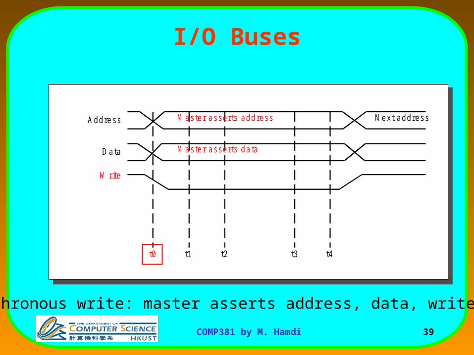
• Asynchronous buses are self-timed and use a handshaking protocol between the sender and receiver.
• This allows the bus to accommodate a wide variety of devices and to lengthen the bus.
• I/O buses are typically asynchronous.– A master (e.g., an I/O channel writing into memory)
asserts address, data, and control and begins the handshaking process.
39COMP381 by M. Hamdi
I/O Buses
Address N ext address
D ata
M aster asserts address
M aster asserts data
W rite
t0 t1 t2 t3 t4
Asynchronous write: master asserts address, data, write buses.
40COMP381 by M. Hamdi
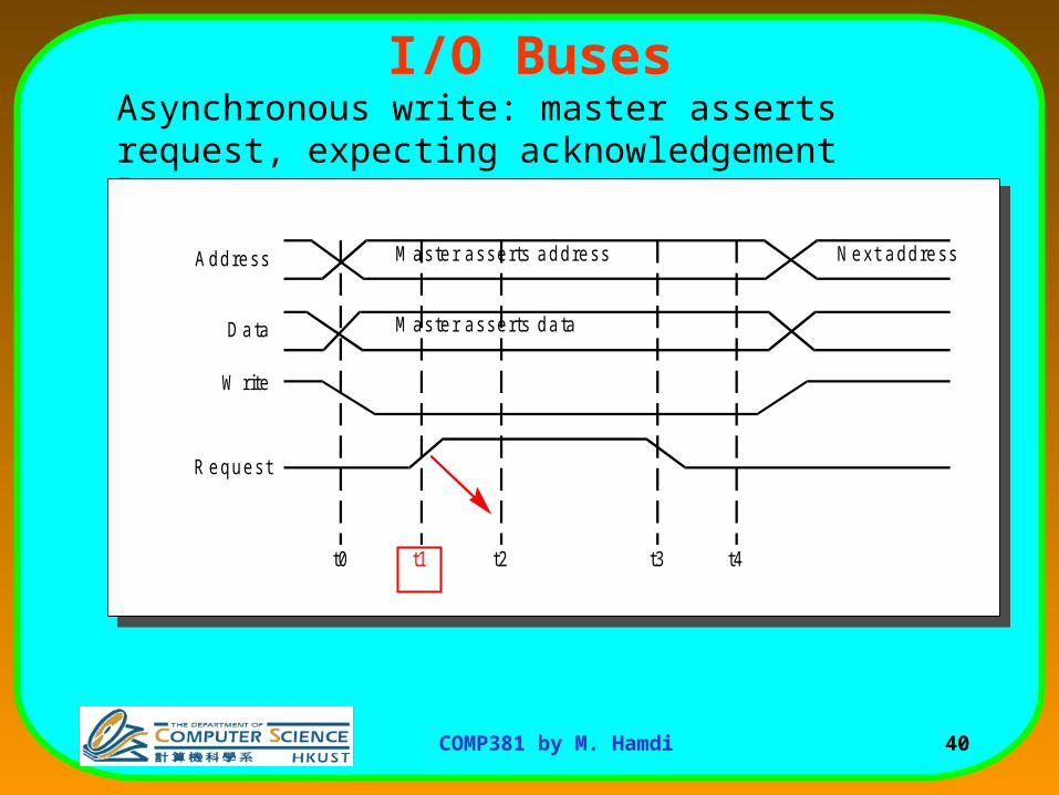
I/O BusesAsynchronous write: master asserts request, expecting acknowledgement later.
Address N ext address
D ata
M aster asserts address
M aster asserts data
W rite
R equest
t0 t1 t2 t3 t4
41COMP381 by M. Hamdi
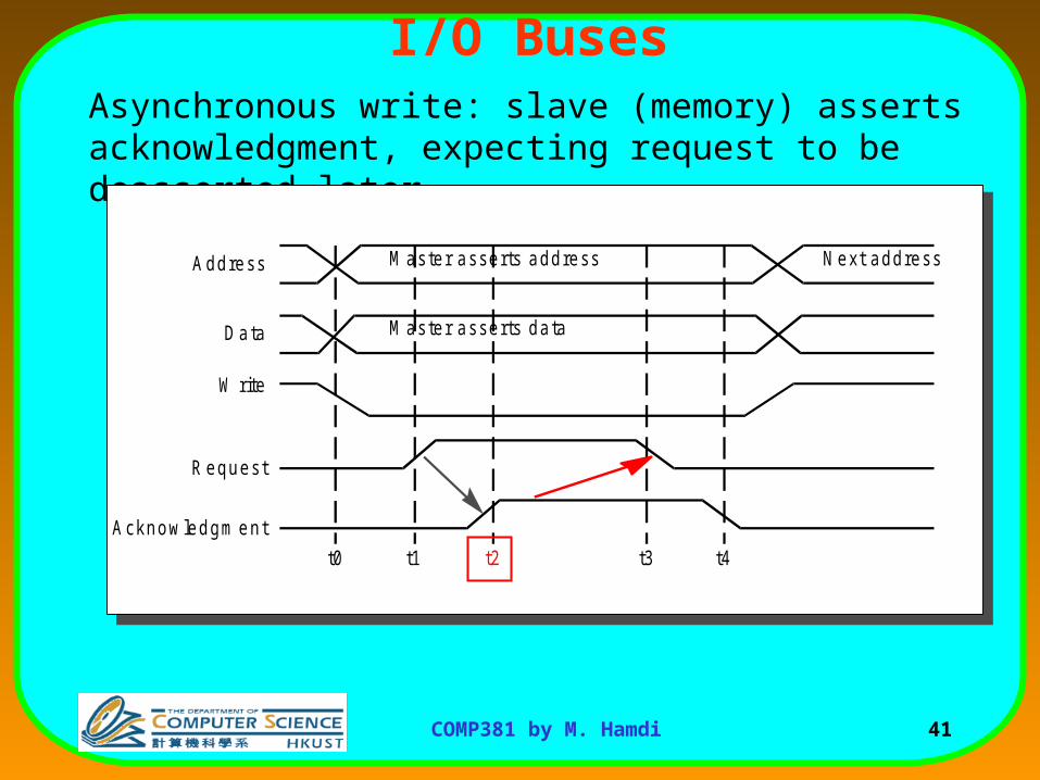
I/O BusesAsynchronous write: slave (memory) asserts acknowledgment, expecting request to be deasserted later.
Address N ext address
D ata
M aster asserts address
M aster asserts data
W rite
R equest
t0 t1 t2 t3 t4
Acknow ledgm ent
42COMP381 by M. Hamdi
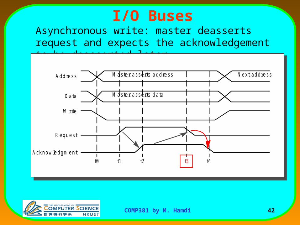
I/O BusesAsynchronous write: master deasserts request and expects the acknowledgement to be deasserted later.
Address N ext address
D ata
M aster asserts address
M aster asserts data
W rite
R equest
t0 t1 t2 t3 t4
Acknow ledgm ent
43COMP381 by M. Hamdi
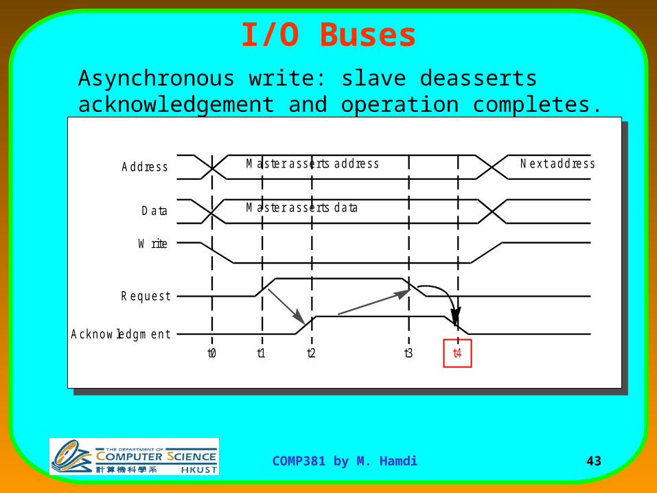
I/O BusesAsynchronous write: slave deasserts acknowledgement and operation completes.
Address N ext address
D ata
M aster asserts address
M aster asserts data
W rite
R equest
t0 t1 t2 t3 t4
Acknow ledgm ent
44COMP381 by M. Hamdi
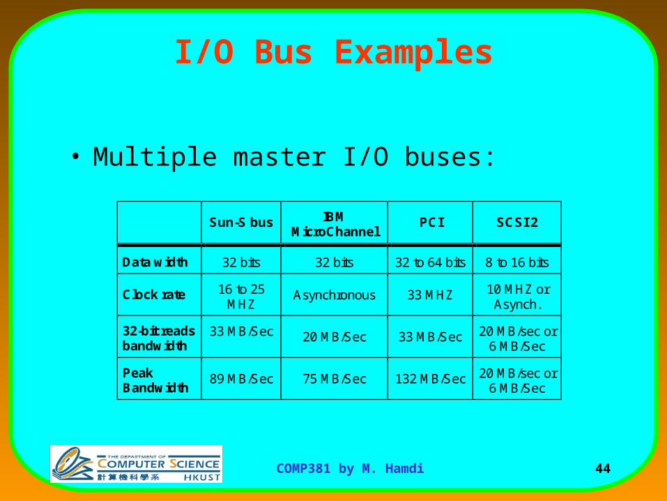
I/O Bus Examples
• Multiple master I/O buses:
Sun-S bus IBMMicroChannel
PCI SCSI 2
Data width 32 bits 32 bits 32 to 64 bits 8 to 16 bits
Clock rate 16 to 25MHZ
Asynchronous 33 MHZ 10 MHZ orAsynch.
32-bit readsbandwidth
33 MB/Sec 20 MB/Sec 33 MB/Sec 20 MB/sec or6 MB/Sec
PeakBandwidth
89 MB/Sec 75 MB/Sec 132 MB/Sec 20 MB/sec or6 MB/Sec
45COMP381 by M. Hamdi
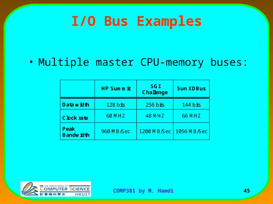
I/O Bus Examples
• Multiple master CPU-memory buses:
HP Summit SGIChallenge
Sun XDBus
Data width 128 bits 256 bits 144 bits
Clock rate 60 MHZ 48 MHZ 66 MHZ
PeakBandwidth
960 MB/Sec 1200 MB/Sec 1056 MB/Sec