Embed Size (px)
Citation preview

COMP210
Physical Layer
Dr Ahmad Al-Zubi

The Physical Layer
• The Physical Layer performs bit by bit The Physical Layer performs bit by bit transmission of the frames given to it transmission of the frames given to it by the Data Link Layer.by the Data Link Layer.
• The specifications of the Physical The specifications of the Physical Layer include:Layer include:
• Mechanical and electrical interfacesMechanical and electrical interfaces
• Sockets and wires used to connect the Sockets and wires used to connect the host to the networkhost to the network
• Voltage levels uses (e.g. -5V and +5V)Voltage levels uses (e.g. -5V and +5V)
• Encoding techniques (e.g. Manchester Encoding techniques (e.g. Manchester encoding)encoding)
• Modulation techniques used (e.g. square Modulation techniques used (e.g. square wave)wave)
• The bit rate and the baud rate.The bit rate and the baud rate.
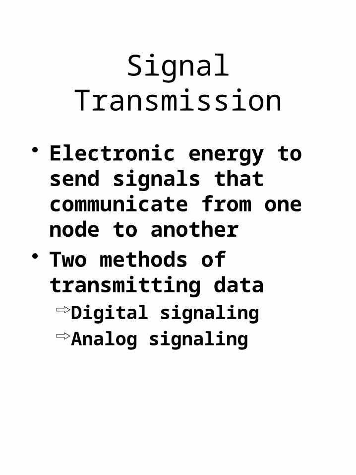
Signal Transmission
Electronic energy to send signals that communicate from one node to another
Two methods of transmitting data Digital signalingAnalog signaling

Comparison of Digital and Analog

Bandwidth-Limited Signals

Bandwidth-Limited Signals
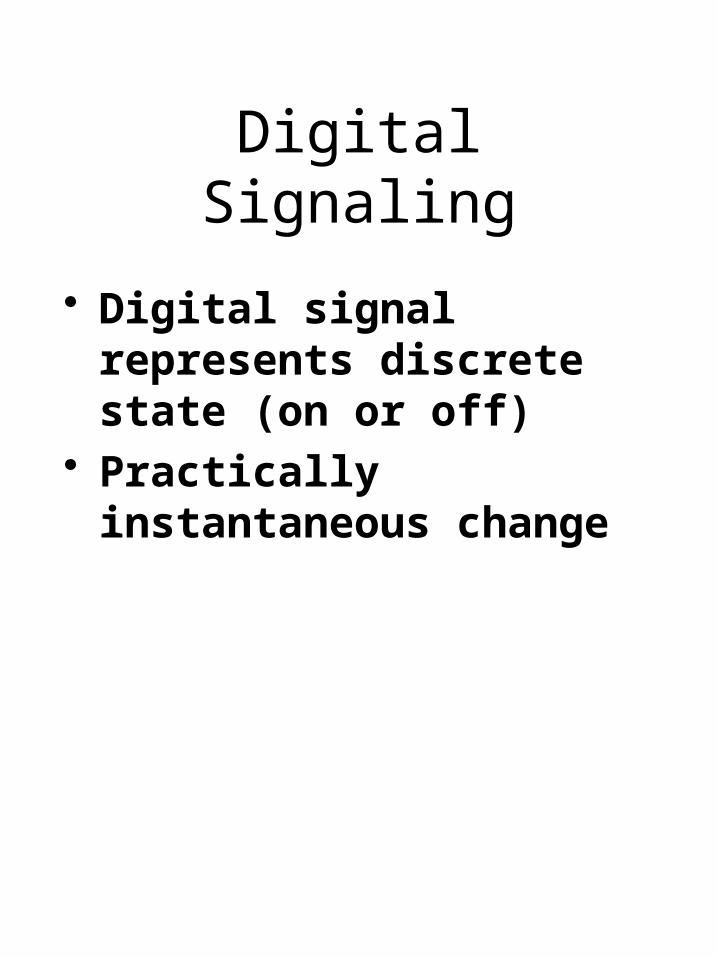
Digital Signaling
Digital signal represents discrete state (on or off)
Practically instantaneous change

Digital SignalingCurrent State
Encoding Data is encoding by the
presence or absence of a signal
A positive voltage might represent a binary zero or binary one or visa versa
The current state indicates the value of the data

Digital Signaling Current State
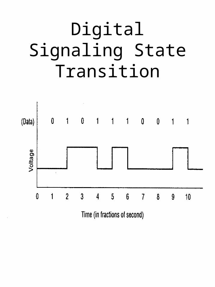
Digital Signaling State Transition

Analog Signaling
Signals represented by an electromagnetic wave
Signal is continuos and represents values in a range
Uses one or more of the characteristics of an analog wave to represent ones and zeros

Characteristics of an Analog Signal

Parts of a Wave The maximum intensity of a wave is
called the amplitude.
The distance between two crests is the wavelength.
The number of complete wave cycles every second is the frequency.
The phase difference measures (as an angle) how far ahead one wave is when compared to another wave.
Phase:
Relative state of one wave to another in regards to timing
Amplitude (a)
Wavelength ()
or period
Phase differenc
e ()
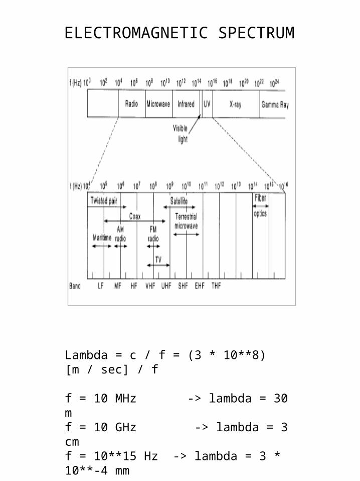
ELECTROMAGNETIC SPECTRUM
Lambda = c / f = (3 * 10**8)[m / sec] / f
f = 10 MHz -> lambda = 30 mf = 10 GHz -> lambda = 3 cmf = 10**15 Hz -> lambda = 3 * 10**-4 mm

Three equations describing data transmissions
1. lambda = c / frequency lambda is the wave length c is the speed of light (3 * 10**8 m/sec)
2. Max_data_rate = 2 * freq * log(2) #of_levels
3. delta(freq) = c * delta(lambda) / lambda ** 2

Wire Propagation Effects
Propagation Effects Signal changes as it travels Receiver may not be able to recognise it
Distance
OriginalSignal
FinalSignal

Propagation Effects: Attenuation
Attenuation: signal gets weaker as it propagatesAttenuation becomes greater with
distanceMay become too weak to recognise
SignalStrength
Distance

Propagation Effects: Distortion
Distortion: signal changes shape as it propagatesAdjacent bits may overlapMay make recognition impossible
for receiver
Distance

Propagation Effects: Noise
Noise: thermal energy in wire adds to signalNoise floor is average noise energyRandom signal, so spikes
sometimes occur
SignalStrength
Time
Signal
Noise
Spike
Noise Floor

Propagation Effects: SNR
Want a high Signal-to-Noise Ratio (SNR)Signal strength divided by average
noise strengthAs SNR falls, errors increase
SignalStrength
Distance
Signal
Noise FloorSNR

Propagation Effects: Interference
Interference: energy from outside the wireAdds to signal, like noiseOften intermittent, so hard to
diagnose
SignalStrength
Time
Signal
Interference

Propagation Effects: Termination
Interference can occur at cable terminator (connector, plug)Often, multiple wires in a bundleEach radiates some of its signalCauses interference in nearby wiresEspecially bad at termination, where
wires are unwound and parallel
Termination

Bandwidth
Capacity of a media to carry information
Total capacity may be divided into channels
A channel is a portion of the total bandwidth used for a specific purpose

Bandwidth
BasebandThe total capacity of the media
is used for one channelMost LANs use baseband
BroadbandDivides the total bandwidth
into many channelsEach channel can carry a
different signalBroadband carries many
simultaneous transmissions

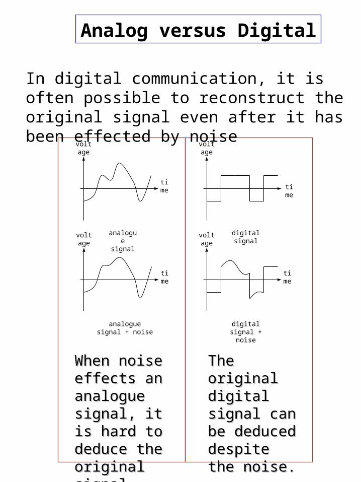
Analog versus Digital
Digital Is less error proneDistortion of the signal between
the source and destination is eliminated
AnalogLittle control over the signal
distortionOld technology
Analog versus Digital
voltage
digital signal
time
analogue signal
time
voltage
time
voltage
analogue signal + noise
time
voltage
digital signal + noise
When noise When noise effects an effects an analogue analogue signal, it is hard signal, it is hard to deduce the to deduce the original signal.original signal.
The original The original digital signal digital signal can be can be deduced deduced despite the despite the noise.noise.
In digital communication, it is often possible to reconstruct the original signal even after it has been effected by noise

Benefits of Digital Transmission
Reliability
Can regenerate slightly damaged signals
There are only two states. Change to closest
E.g., if two states are voltages +10v (1) and -10v (0) and the signal is +8v, the signal is a 1
Original ReceivedRegenerated

Benefits of Digital Transmission
Error detection and correctionCan correct errors in
transmission
- Add a few bytes of error-checking information
- Can ask for retransmission if an error is detected

Benefits of Digital Transmission
EncryptionEncrypt (scramble) messages so
that someone intercepting them cannot read them

Benefits of Digital Transmission
CompressionCompress message before
transmissionDecompress at other endCompressed message places
lighter load on transmission line, so less expensive to send
Not always used
10101001 1010
OriginalSignal
CompressedSignal

• Because attenuation is frequency dependent, modems use a sine wave carrier of a particular frequency, and then modulate that frequency. Various modulations include:
Amplitude modulation: Two different amplitudes of sine wave are used to represent 1's and 0's.
Frequency modulation: Two (or more) different frequencies, close to the carrier frequency, are used.
Phase modulation: The phase of the sine wave is changed by some fixed amount.
Binary Signal
Modulation

Nyquist’s Limit
Suppose we know the bandwidth (H) of a channel and the number of signal levels (V) being used. What is the maximum number of bit we could transmit?
Nyquist’s Limit says:
Max_bps = 2*H*log(base 2)(V)
For example, if the bandwidth is 3100Hz and we are using 16 level modulation then the maximum number of bits per second is:
max_bps = 2 3100 log2(16) = 24800 bps
bits/sec

Analog Signaling Amplitude Modulation
(ASK)

Analog Signaling Frequency Modulation
(FSK)

Analog Signaling Phase Shift Keying
(FSK)
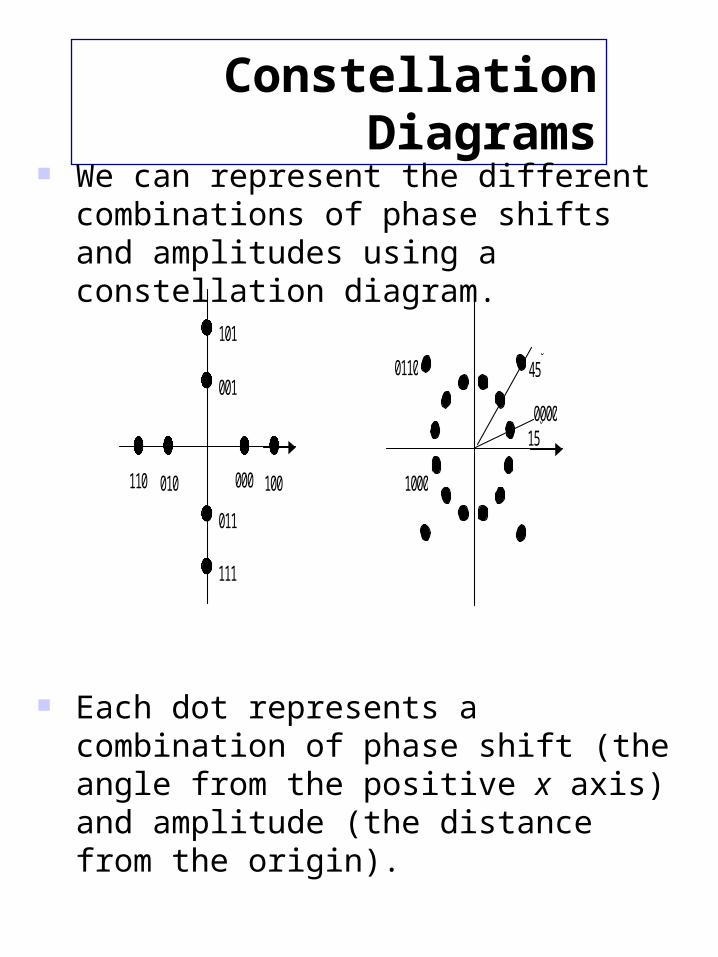
Constellation Diagrams
We can represent the different combinations of phase shifts and amplitudes using a constellation diagram.
Each dot represents a combination of phase shift (the angle from the positive x axis) and amplitude (the distance from the origin).
15
45
000
111
110
101
100010
001
011
0110
1000
0000

Baud Rate / Bit Rate
The maximum number of times a signal can change in a second is called the baud rate.
The number of bits (1s and 0s) transmitted in a second is called the bit rate.
In the examples we have seen so far, the bit rate and the baud rate are the same. This is not always the case.
The bit rate can be higher than the baud rate if we use more than two signal levels (more later on…).

Modems
Modulation demodulation Used to connect a digital
computer to an analog phone system
Can be installed internally a card inserted into the motherboard
Can be connected to the serial port (external modem)

Modems
Transfer speedsBit rate BPSBaudBandwidth
Compressionappears to increases speed by
decreasing the number of bits sent (usually some data does not compress well)
sending and receiving modem must use same compression standard
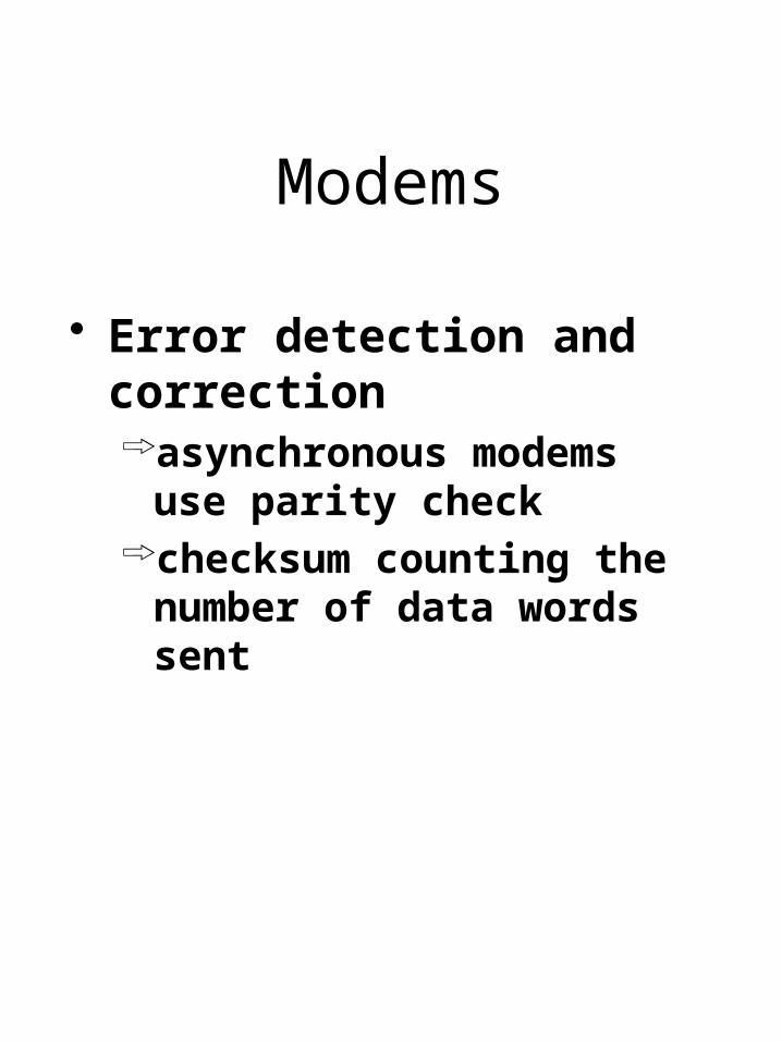
Modems
Error detection and correctionasynchronous modems use
parity checkchecksum counting the number
of data words sent

Digital Modem
Miss named Used to connect to a
digital telephone ISDN (integrated Services
Digital Network) is an example
Again do not connect digital modems to an analog phone
Higher quality lower errors

Transmission Modes
Parallel Mode
Serial Mode
Channel Types
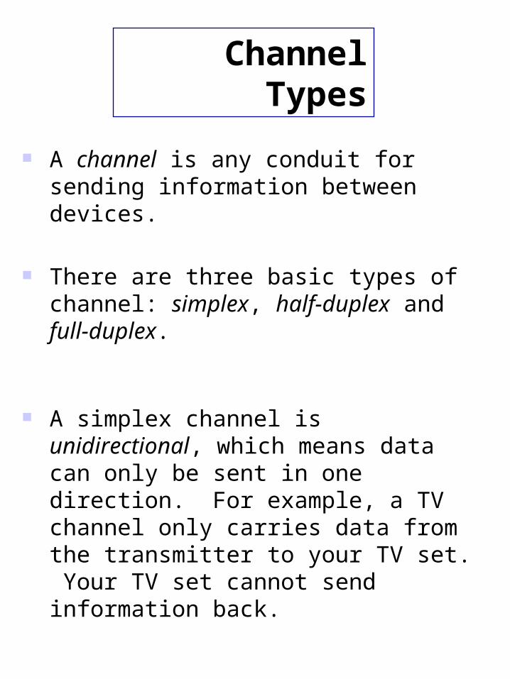
A channel is any conduit for sending information between devices.
There are three basic types of channel: simplex, half-duplex and full-duplex.
A simplex channel is unidirectional, which means data can only be sent in one direction. For example, a TV channel only carries data from the transmitter to your TV set. Your TV set cannot send information back.

Channel Types
A half-duplex channel allows information to flow in either direction (but not simultaneously).
Devices at either end of the channel must take it in turns to transmit information whilst the other listens. For example, a walky-talky either transmits or receives but not both at the same time.

Channel Types
A full-duplex channel allows data to be sent in both directions simultaneously.
A full-duplex channel can be formed from two simplex channels carrying data in opposite directions. This may make it more expensive than a half-duplex channel.
There is no waiting for turns or for the devices swap roles, as is the case with a half-duplex channel. This means full-duplex can be faster and more efficient.
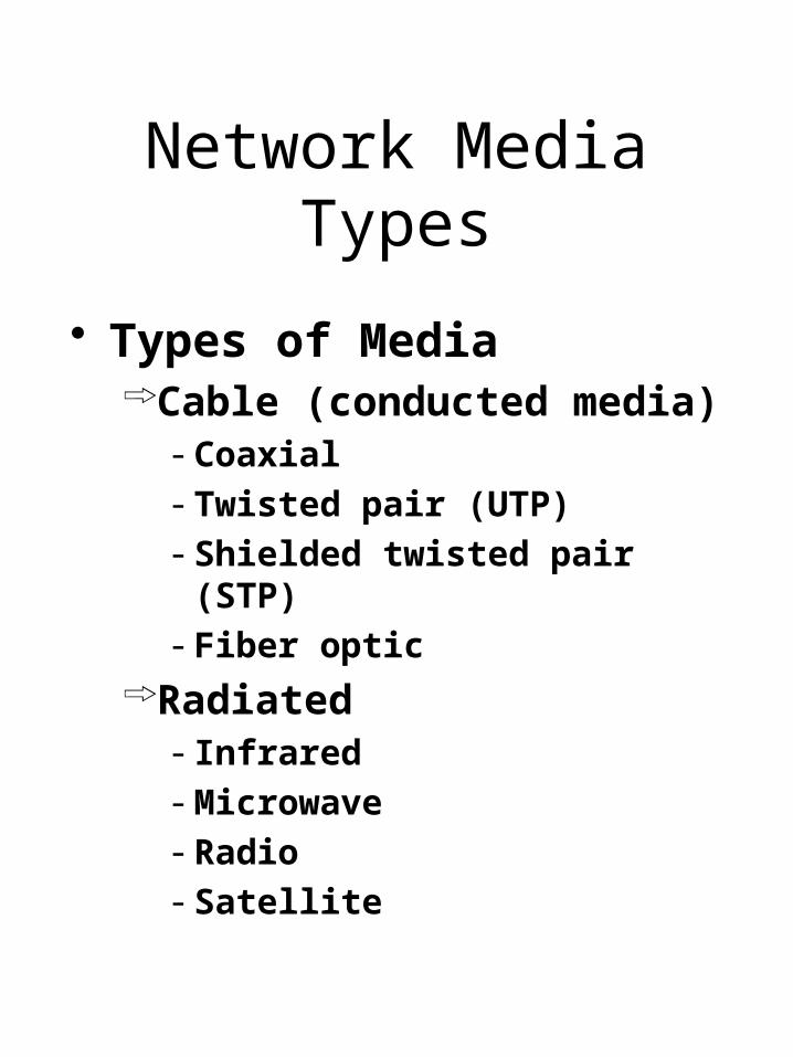
Network Media Types
Types of MediaCable (conducted media)
- Coaxial- Twisted pair (UTP)- Shielded twisted pair (STP)- Fiber optic
Radiated- Infrared- Microwave- Radio- Satellite

Media Selection Criteria
CostFor actual media and
connecting devices such as NICs hubs etc
InstallationDifficulty to work with mediaSpecial tools, training
Media Selection Criteria
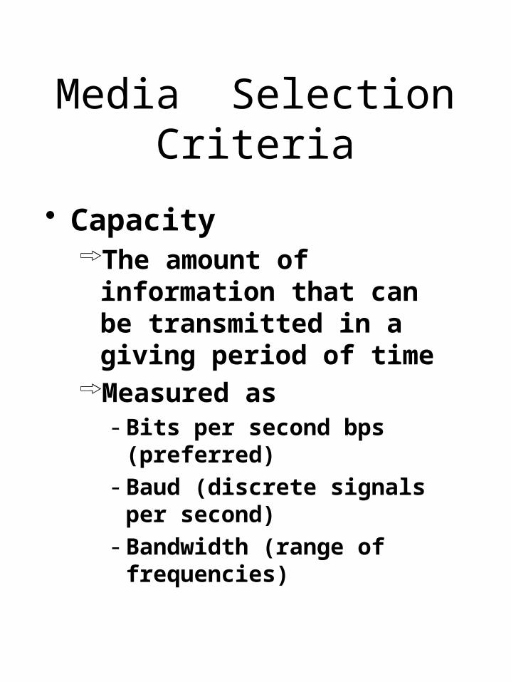
CapacityThe amount of information that
can be transmitted in a giving period of time
Measured as- Bits per second bps (preferred)- Baud (discrete signals per
second)- Bandwidth (range of
frequencies)

Media Selection Criteria
Node CapacityNumber of network devices that
can be connected to the media
AttenuationWeakening of the signal over
distance

Media Selection Criteria
Electromagnetic Interference (EMI)Distortion of signal caused by
outside electromagnetic fieldsCaused by large motors,
proximity to power sources
Other noise sourcesWhite (Gaussian) noiseImpulse noiseCrosstalkEcho

Cable Media
Unshielded Twisted Pair UTP
Shielded Twisted Pair STP Coaxial Fiber optic

Unshielded Twisted Pair (UTP)
One or more pairs of twisted copper wires insulated and contained in a plastic sheath
Twisted to reduce crosstalk

Unshielded Twisted Pair (UTP)
Categoriescategories 1 and 2
- voice grade - low data rates up to 4 Mbps
category 3- suitable for most LANs- up to 16 Mbps
category 4- up to 20 Mbps

Unshielded Twisted Pair (UTP)
Categoriescategory 5
- supports fast ethernet- more twists per foot- more stringent standards on
connectors
Data grade UTP cable usually consists of either 4 or 8 wires, two or four pair
Uses RJ-45 telephone connector

Unshielded Twisted Pair (UTP)

Shielded Twisted Pair (STP)
Same as UTP but with a aluminum/polyester shield
Connectors are more awkward to work with
Usually comes in pre made lengths
Different standards for IBM and Apple

Shielded Twisted Pair (STP)

Coaxial Cable Coax
Two conductors sharing the same axis
A solid center wire surrounded insulation and a second conductor

Coaxial Cable

Coaxial Cable Coax
Size of CoaxRG-8, RG-11
- 50 ohm Thick Ethernet
RG-58- 50 ohm Thin Ethernet
RG-59- 75 ohm Cable T.V.
RG-62- 93 OHM ARCnet

Fiber Optic Cable
Thin strand(s) of glass or plastic protected by a plastic sheath and strength wires or gel
Transmits laser (single mode) or LED (multi mode)
Single mode more expensive but can handle longer distances

Fiber Optics
Three examples of a light ray from inside a silica fiber impinging on the air/silica boundary at different angles.
Light trapped by total internal reflection.

The main advantage of optical fiber is the great bandwidth it can carry.
There are three main bands of wavelength used.
Wavelen (microns)
0 0.8
0.9
1.0
1.1
1.2
1.3
1.4
1.5
1.6
1.7
1.8
1.55 band
1.30 band
0.80 band
Attenuat
dB/km
0.5
1.0
1.5
2.0
Optical Fibers

One problem with optical fibers is that the light pulses become distorted over distance due to dispersion.
Dispersion occurs when photons from the same light pulse take slight different paths along the optical fiber. Because some paths will be longer or shorter than other paths the photons will arrive at different times thus smearing the shape of the pulse.
Over long distances, one pulse may merge with another pulse. When this happens, the receiving device will not be able to distinguish between pulses.
Optical Fibers

Normal fiber optic cable is called multimode because photons can take different paths along it. The more expensive monomode fibre optic overcomes dispersion by having a core so thin that the light can only take one path along it.
Overcoming Dispersion

Fiber Optic Networks
A fiber optic ring with active repeaters.

Fiber Optic NetworksStar connection

Fiber Cables
A comparison of semiconductor diodes and
LEDs as light sources.

Characteristics of Cable Media

Wireless Media
Uses the earth’s atmosphere as a conducting media
Main typesradio wavemicrowave (including satellite)infrared
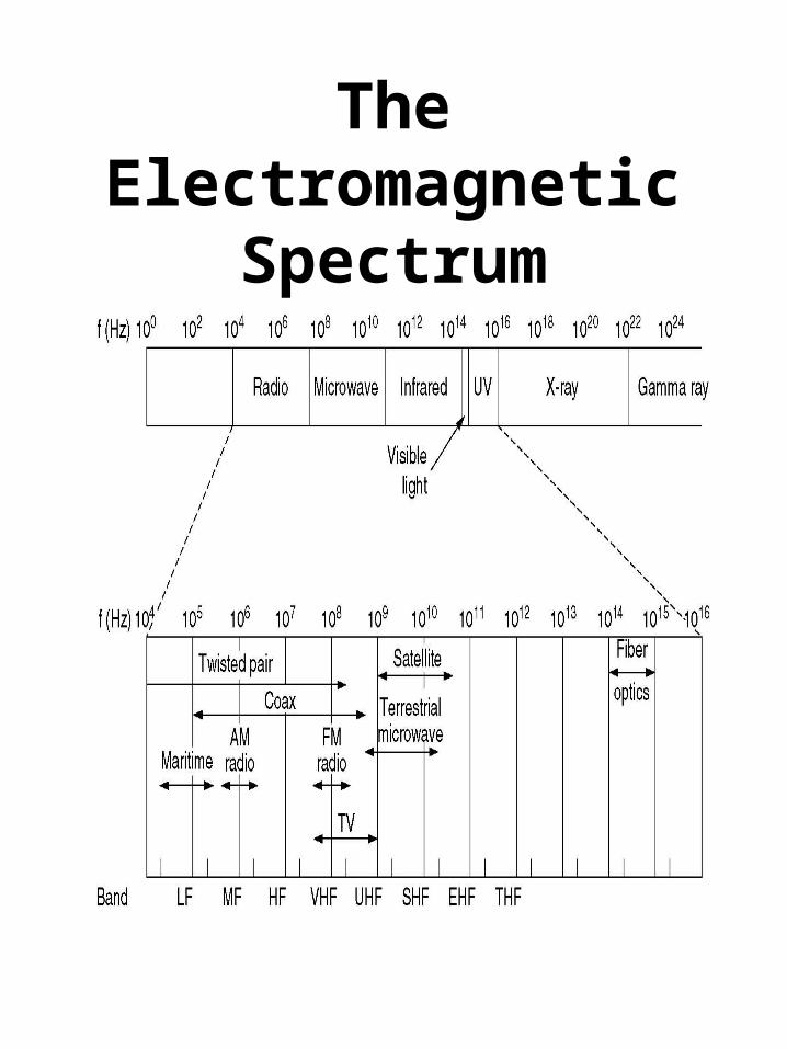
The Electromagnetic Spectrum
The electromagnetic spectrum and its uses for
communication.

Radio Transmission
(a) In the VLF, LF, and MF bands, radio waves follow the curvature of the earth.
(b) In the HF band, they bounce off the ionosphere.

Radio Wave
Most radio frequencies are regulated
Must obtain a license from a regulatory board (CRTC, FCC)
A range of radio frequencies are unregulated

Radio Wave
Low power single frequencyuses one frequencylimited range 20 to 30 metersusually limited to short open
environments

Radio Wave
High power single frequencylong distance may use repeaters
to increase distanceline of sight or bounced of the
earth’s atmosphereuses a single frequency

Radio Wave
Spread Spectrum
Maintains security of the radio
transmission by:
1. Spreading the carrier signal frequency
2. Modulating the carrier frequency by a Pseudo Random signal

Radio Wave
Spread Spectrum
Two methods:1. Frequency hopping – carrier
frequency keeps on changing according to the Pseudo Random code
2. Direct Sequence Spread Spectrum- Pseudo Random digital signal modulates the carrier directly
Transmitter and receiver must use the
same Pseudo Random code

Radio Wave
Spread Spectrum
Direct Sequence Spread Spectrum (DSSS) is used as the Physical Layer for the Mobile networking (IEEE 802.11)

Radio Wave

Microwave
Terrestrial line of sightuse relay towersuses license frequencies

Communication Satellites

Communication Satellites
One disadvantage of satellite transmission is the delay that occurs because the signal has to travel out into space and back to Earth (propagation delay).
One problem associated with some types of satellite transmission is raindrop attenuation (some waves at the high end of the spectrum are so short they can be absorbed by raindrops).

Communication Satellites
The principal satellite bands.

Communication Satellites
VSATs using a hub.
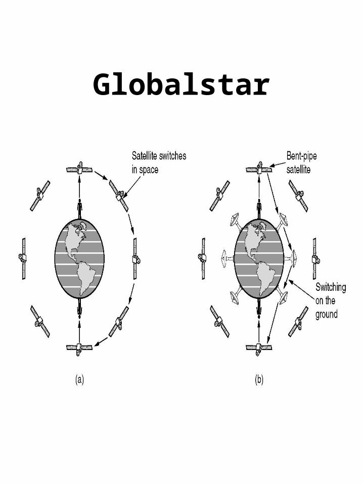
Globalstar

Infrared
Uses same technology as remotes for T.V.
signals can not penetrate objects
Can be point to point or broadcast
Point to point requires precise alignment of devices
Point less immune to eavesdropping

Multiplexing
several lines (one for each device) enter a multiplexer (mux) at the host side
the host side mux combines all incoming signals
combined signals are transmitted to a mux on the receiving side

Types of Multiplexers
Frequency Division Multiplexing (FDM)
Time Division Multiplexing (TDM)
Statistical Time Division Multiplexing (STDM)

Frequency Division Multiplexing
• The frequency spectrum is divided up among the logical channels - each user hangs on to a particular frequency. The radio spectrum (and a radio) are examples of the media and the mechanism for extracting information from the medium.
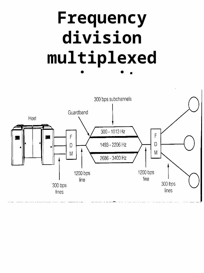
Frequency division multiplexed circuit

Frequency Division Multiplexing
One problem with FDM is that it cannot utilise the full capacity of the cable.
It is important that the frequency bands do not overlap. Indeed, there must be a considerable gap between the frequency bands in order to ensure that signals from one band do not affect signals in another band.
FDM is usually used to carry analogue signals although modulated digital signals can also be sent using this technique.

Wavelength Division Multiplexing
• The same as FDM, but applied to fibers. There's great potential for fibers since the bandwidth is so huge (25,000 GHz).
• Fibers with different energy bands are passed through a diffraction grating prism• Combined on the long distance link• Split at the destination
• High reliability, very high capacity

Time Division Multiplexing (TDM)
Like FDM, time division multiplexing (TDM) saves money by allowing more than one telephone call to use a cable at the same time.
Instead of dividing the cable into frequency bands, TDM splits cable usage into time slots. Each channel is given a regular time slot in which to send a PCM signal.
Terminal#1
Terminal#2
Terminal#3
Multiplexer
Device#1
Device#2
Device#3
Demultiplexer
#3 #2 #1#3 #2 #1

Time Division Multiplexing
• In TDM, the users take turns, each one having exclusive use of the medium in a round robin fashion. TDM can be all digital.

Time Division Multiplexing

Statistical Time Division Multiplexing
(STDM) allows connection of more
nodes to the circuit than the capacity of the circuit
works on the premise that not all nodes will transmit at full capacity at all times
must transmit a terminal identification
may require storage

Digital Technology in Telephone Networks
Over the past 30 years, much of the traditional analogue telephone network has been replaced by digital technology.
A device called a codec (coder/decoder) is used to convert analogue voice signals into digital information that can be handled by the digital technology.

WAN Transmission Media
Public Switched Telephone Network
High speed, High bandwidth dedicated leased circuits
High speed fiber optic cable
Microwave transmission links
Satellite links

Services provided by PSTN
Voice – Plain Old Telephone Service (POTS)
Based on the Voice Channel (3600 Hz)
Data transmission servicesconsist of services such as :
- switched 56- X.25- T1, T3 circuits- Frame relay- ISDN- ATM

Switching
Switching send data across different routes
Three types of switchingCircuit switchingMessage switchingPacket switching

Switching
Circuit Switching: A connection (electrical, optical, radio) is established from the caller phone to the callee phone. This happens BEFORE any data is sent.
Message Switching: The connection is determined only when there is actual data (a message) ready to be sent. The whole message is re-collected at each switch and then forwarded on to the next switch. This method is called store-and-forward. This method may tie up routers for long periods of time - not good for interactive traffic.
Packet Switching: Divides the message up into blocks (packets). Therefore packets use the transmission lines for only a short time period - allows for interactive traffic.

Circuit Switching
Connects the sender and receiver by a single physical path for the duration of the session
PSTN uses circuit switching
Before transmission a dedicated circuit must be established

Circuit Switching
Advantagesguaranteed data rateonce connected no channel
access delay
Disadvantagesinefficient use of the
transmission media (idle time)long connection delays (first
time)

Message Switching
Each message is treated as an independent unithas its own source and
destination address
Each is transmitted from device to device
Each intermediate device stores the message until the next device is readystore and forward
Message Switching
Route messages along varying paths for more efficiency
Switching devices are often PCs with special software
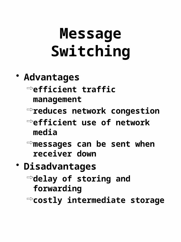
Message Switching
Advantagesefficient traffic managementreduces network congestionefficient use of network mediamessages can be sent when
receiver down
Disadvantagesdelay of storing and forwardingcostly intermediate storage

Packet Switching
Packet switching breaks messages into packets
Packets travel different routes (independent routing)
Each packet has its own header information
Packets small enough to be stored in RAM thus quicker than message switching

Packet Switching Advantages
improves the use of bandwidth over circuit switching
can adjust routes to reflect network conditions
shorter transmission delays than message switching (stored in RAM)
less disk spacesmaller packets to retransmit

Packet Switching
DisadvantagesMore RAMMore complex protocols more processing power for
switching deviceGreater number of packets
greater chance for packet loss or damage

Packet Switching
Two methods of packet switchingDatagram packet switchingVirtual circuit packet switching
Datagram Packet Switching
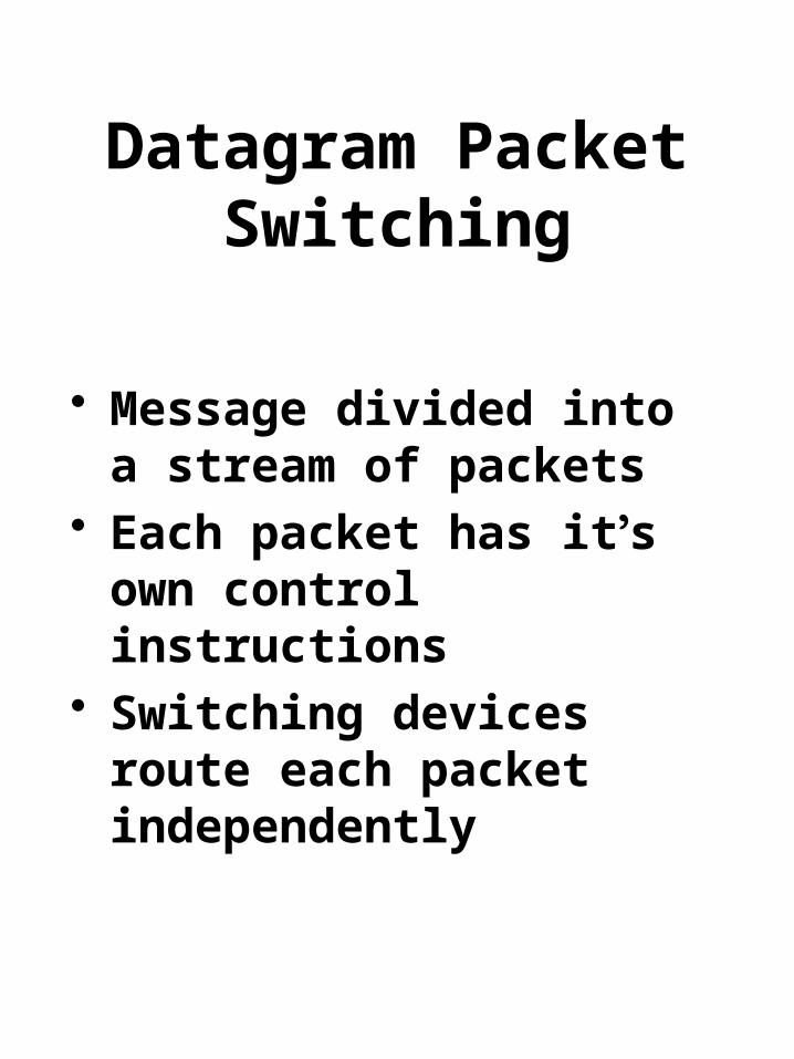
Message divided into a stream of packets
Each packet has it’s own control instructions
Switching devices route each packet independently

Datagram Packet Switching
Switching devices can route packets around busy network links
Require sequence numbers to reassemble
Small packet size facilitates retransmission due to errors

Virtual Circuit Packet Switching
Similar to circuit switching Before transmission of the
sending and receiving device agree on:maximum message sizenetwork pathestablish a logical connection
(virtual circuit)
All packets travel on the same virtual path

CIRCUIT SWITCHED versus PACKET SWITCHED NETWORKS

(a) circuit switching(b) message switching(c) packet switching

NARROWBAND ISDN - WHAT IS IT?
Integrated Services Digital Network: A completely digit, circuit-switched phone system. Integrates voice and non-voice services.
ISDN allows integration of computers and voice. It means that caller ID can be used to look up your account on the computer so that by the time a human answers the phone, a screen has your information already available.

Integrated Services Digital Network
ISDN SYSTEM ARCHITECTURE:
• ISDN uses TDM to handle multiple channels. For home use, the NT1 (Network Terminator) connects the twisted pair going to the phone company with the house wiring. Various ISDN devices can be connected to this NT1.
• Businesses may have more channels active than the home configuration internal bus can handle. So a PBX ( Private Branch eXchange ) is used to provide the internal bus containing more switching capacity. This in turn is connected to NT1.

Integrated Services Digital Network
THE ISDN INTERFACE:
• Typically a number of channels are combined together. In the USA, Primary Rate ISDN contains 23 channels (each 64 kbps carrying voice or data) + 1 channel for signaling and control (16 kbps digital channel.) In Europe, instead of 23 channels, 30 are used.
• The primary Rate is designed to connect to a business with a PBX. As it turns out, most companies now need far more capacity than 64 kbps for the many uses beyond voice. So this is less than adequate.
• N-ISDN may have a life as a connection to homes for people wanting to download images etc. But it's not useful for serious business applications.

B-ISDN (Broadband Integrated Services
Digital Network)
Broadband transmission A type of data transmission in which a single medium (wire) can carry several channels at once (ex. Cable TV).
Baseband transmission one signal at a time (most communication between computers).
B-ISDN will offer video on demand, live television from many sources, full motion multimedia email, CD-quality music, LAN interconnection, high-speed data transport for science and industry and many more, ALL over the telephone line.
A digital virtual circuit capable of 155 Mbps
Underlying technology that makes B-ISDN possible ATM (Asynchronous Transfer Mode)

Comparing Virtual Circuits and Circuit Switching
• Permanent virtual circuits that remain in place for long periods of time.
• Switched virtual circuits that are set up and torn down with each request.
• The method for establishing these circuits is shown in the Figure. The circuit is really entries in a series of switches, each mapping a circuit number onto a forwarding line.
A Virtual Circuit A kind of circuit-switched path implemented with packet switching
The service offered is connection oriented (from the customer's point of view) but is implemented with packet switching. Services offered include:

Why all the interest in ATM? These days it is more common
for companies to want to interconnect networks. There is one international standard for ATM networks and so interconnection is easier.
ATM can be used to provide both LAN and WAN networks.
ATM can be made to behave like other standard networks and so you do not have to throw away all your old equipment.
ATM provides a high speed network.

ATM Technology
ATM is based on Cell Relay technology. This uses virtual circuits to carry small packets (just 53 bytes long) over a predetermined path through the network.
Section of the path can be shared by other virtual circuits, thus ensuring that the network is used more efficiently than in the case of circuit switching.
Little error checking is performed by the network (this keeps overheads down). Instead, the transmitting and receiving hosts are responsible for error checking.
Establishing a Connection
When information needs to be communicated, the sender NEGOTIATES a "requested path" with the network for a connection to the destination.
When setting up this connection, the sender specifies the type, speed and other attributes of the call, which determine the end-to-end quality of service.
The network then determines a path through the network, and sets up a virtual circuit along this path.
An analogy for this is sending mail. One can choose to send 1st class, overnight, 2 day delivery, etc. and can ask for certified mail.

ATM Cells
The format of the ATM cell looks The format of the ATM cell looks like this:like this:
5 bytes (40 bits) are used to carry 5 bytes (40 bits) are used to carry header data and the remaining 48 header data and the remaining 48 bytes carry data.bytes carry data.
The Virtual Channel ID is used The Virtual Channel ID is used identify which virtual circuit the identify which virtual circuit the cell is to be routed along.cell is to be routed along.
Bits:
VCI Payload48 bytes
3
T
T
12
VPI
VCI
P
H CRC
16
P
1
HCRC
8
VPI
Payload Type
Virtual Path ID
Virtual Channel ID
Priority
Header Checksum

ATM Cell Transmission
– – Unlike in synchronous Unlike in synchronous communication, there is no communication, there is no requirementrequirement that cell input rigidly that cell input rigidly alternate among sourcesalternate among sources
– – Continuous cell stream is not Continuous cell stream is not requiredrequired
– – ATM cells can be transmitted on ATM cells can be transmitted on many types of transmissionmany types of transmission technologiestechnologies
– – ATM current common speed is ATM current common speed is 155Mbps (OC3c), 622Mbps155Mbps (OC3c), 622Mbps
(OC12) and 45Mbps (T3) also getting (OC12) and 45Mbps (T3) also getting common.common.
– – Fiber media preferred. Short runs Fiber media preferred. Short runs may be coax or twisted pair.may be coax or twisted pair.

ATM Speed
ATM can deliver data at rates of either 155.52 Mbps or 622.08 Mbps and higher data rates are likely to follow.
ATM can operate at these high speed because specialised switching mechanisms have been developed that can switch the short 53 byte cells very quickly through the network.
ATM can work over a variety of media. Coaxial cable and optical fibre are the most commonly used.
ATM technology is currently being used to develop the next generation of high-bandwidth telephone systems.

ATM Switches
Operation
– Cells arrive at 360000 cells/sec per 155Mbps connection• Cycle time of 2.7 ms
– Many ports per switching fabric• Fixed size cells facilitate fast switching
– Switch cells• Keep discard rate very low• Never reorder cells on virtual circuit
– Problem: Two cells destined for same output– Problem: Head-of-line blocking