Embed Size (px)
Citation preview
Vision Fire & Security
Communications GuideMarch 7, 2005
Part: 30006

VESDA® Communications Guide
i
Copyright InformationThis document is protected by copyright under the laws of Australia and other jurisdictions throughout the world. It must not by any means, either in whole or part, be reproduced, communicated to the public, adapted, distributed, sold, modified, published except as permitted by any laws or statute or with prior written consent of VFS International Pty Ltd. Copyright© 2004 VFS International Pty Ltd ACN 100 259 381
DisclaimerThe manufacturer reserves the right to change designs or specifications without obligation and without further notice. VESDA, LaserTEKNIC, LaserPLUS, LaserSCANNER, LaserCOMPACT, LaserFOCUS, VESDAnet, VESDAlink, ASPIRE, ASPIRE2, AutoLearn, VSM, VConfig, InfoWORKS, PROACTIV, PRECISION, VSC, ADPRO, FastTrace, FastVu, FastScan, Axiom, PRO, Amux, Video Central, Millbank and VxLAN are brands and trade marks used under license by the distributor.
FCC Compliance StatementThis equipment has been tested and found to comply with the limits for a Class B digital device, pursuant to part 15 of the FCC Rules. These limits are designed to provide reasonable protection against harmful interference in a residential installation. This equipment generates, uses and can radiate radio frequency energy and, if not installed and used in accordance with the instruction, may cause harmful interference to radio communications. However, there is no guarantee that interference will not occur in a particular installation. If this equipment does cause harmful interference to radio or television reception, the user is encouraged to try to correct the interference by one or more of the following measures; re-orientate or relocate the receiving antenna, increase the separation between the equipment and receiver, connect the equipment to a power outlet which is on a different power circuit to the receiver or consult the dealer or an experienced radio/television technician for help.
General WarningThis product must only be installed, configured and used strictly in accordance with the General Terms and Conditions and the technical documentation available from VFS International Pty Ltd (VFS). You acknowledge that you have read and agree to those terms and conditions. All proper health and safety precautions must be taken during the installation, commissioning and maintenance of the product. The product should not be connected to a power source until all the components have been installed. Proper safety precautions must be taken during tests and maintenance of the products when these are still connected to the power source. Failure to do so or tampering with the electronics inside the products can result in an electric shock causing injury or death and may cause equipment damage. VFS is not responsible and cannot be held accountable for any liability that may arise due to improper use of the equipment and/or failure to take proper precautions. Only persons trained through an accredited VFS training course can install, test and maintain the product.
Limitation of LiabilityThis product must only be installed, configured and used strictly in accordance with the General Terms and Conditions, this manual and the technical documentation available from VFS International Pty Ltd. You acknowledge that you have read and agree to those terms and conditions.You acknowledge that you have been provided with a reasonable opportunity to appraise the product and have made your own independent assessment of the fitness or suitability for your purpose. You acknowledge that you have not relied on any oral or written information, representation or advice given by or on behalf of VFS or its representatives.VFS has no liability to you or any person for incidental or consequential loss, expense or damages including, without limitation, loss of business, loss of profits or loss of data. You indemnify VFS for any claim, amount or liability brought against VFS in connection with the product.You expressly agree that you assume the entire risk as to the results and performance of the product resulting from the configuration of the product. VFS does not warrant, guarantee or make any representations, either expressly or implied, regarding the current or future use, or the results of the use, of the product, with respect to its correctness, accuracy, reliability, completeness, interworking, functionality, currentness or otherwise resulting from the configuration of the product.To the full extent permitted by law, VFS expressly excludes all conditions, warranties and liability, whether imposed or implied by statute or by rule of law or otherwise, which are not expressly set out in the General Terms and Conditions. To the extent permitted by law, your sole recourse for any defect of, damage to, or performance standard of the product will be under the express warranties the General Terms and Conditions (if applicable) and VFS will in no event be liable to pay any amount or damages resulting from or in connection with the product. To the extent by law that any limitation or exclusion can not apply, the total liability of VFS in relation to the product is limited to: (i) in the case of services, the cost of having the services supplied again; or (ii) in the case of goods, the lowest cost of replacing the goods, acquiring equivalent goods or having the goods repaired.To the extent permitted by law, VFS has no liability with respect to damage to or arising out of, or the condition or performance of, the product resulting from (i) negligence or improper use, storage, installation, configuration commission, service maintenance or handling of the product (where 'improper' includes treatment other than in accordance with the product manual, these terms and conditions or the information provided at a training session); (ii) accident, unforeseeable circumstances or disaster; (iii) modifications to the product other than in accordance with VFS's instructions; (iv) attachment of or interoperation with features, software or products not approved by VFS in writing; or (v) where the product has been serviced by persons not authorized by VFS in writing to service the product.
Product Warranty ConditionsVFS International Pty Ltd (VFS) warrants that new products (excluding consumable items) will conform to its published specifications and remain in good working order during the warranty period of 24 (twenty four) months from the date an invoice is issued by VFS to its distributor.VFS also warrants that products serviced or repaired by its service department will remain in good working order for a warranty period of 12 (twelve) months from the date of service. This service or repair warranty is only available on products less than 7 (seven) years old and only covers those component parts of the products serviced, repaired or replaced. Should product under warranty not be in good working order, VFS will, at its option, either repair or replace the product or its component parts at no additional charge.Spare parts and replacement product, covered under this warranty, will be furnished on an exchange basis and will, at the option of VFS either be new, equivalent to new or reconditioned. Returned parts and products to VFS become the property of VFS.This warranty does not cover the repair or damage to the product resulting from or arising out of (i) negligence or improper use storage, installation, configuration, commission, service, maintenance or handling of the product (where 'improper' includes treatment other than in accordance with any manual or instructions for use of the product); (ii) accident, unforeseeable circumstances or disaster; (iii) modifications to the product other than in accordance with VFS's instructions; (iv) attachment of features or interoperation with features, software or products not approved by VFS in writing; or (v) where the product has been serviced by persons not authorized by VFS in writing to service the product.
Communications Guide VESDA®
ii
Document ConventionsThe following typographic conventions are used in this document.
The following icons are used in this document
Contact Us
www.vesda.com www.adpro.com.au www.millbank.co.uk
Codes and Standards InformationWe strongly recommend that this document is read in conjunction with the appropriate local codes and standards for smoke detection systems and electrical connections. This document contains generic information and some sections may not comply fully with all local codes and standards. In these cases, the local codes and standards must take precedence.
FM 3611 Hazardous Approval WarningExposure to some chemicals may degrade the sealing of relays used on the detector. Relays used on the detector are marked "TX2-5V" or "G6S-2-5V" or "EC2-5NU".
UL WarningThe fire alarm threshold (signal) that initiates an evacuation procedure via the Fire Alarm Panel must not be set higher than 0.625%/ft. The detector can send this signal either via the Fire Alarm Panel Output signal or the Pre-alarm output signal.
Safety LabelThis VESDA product incorporates a laser device and is classified as a Class 1 laser product that complies with FDA regulations 21 CFR 1040.10. The laser is housed in a sealed detector chamber and contains no serviceable parts. This laser emits invisible light and can be hazardous if viewed with the naked eye. Under no circumstances should the detector chamber be opened.
Convention Description
Bold Used to denote: emphasisUsed for names of menus, menu options, toolbar buttons
Italics Used to denote: references to other parts of this document or other documents. Used for the result of an action
Convention Description
Caution: This icon is used to indicate that there is a danger to equipment. The danger could be loss of data, physical damage, or permanent corruption of configuration details.
Warning: This icon is used to indicate that there is a danger of electric shock. This may lead to death or permanent injury.
Warning: This icon is used to indicate that there is a danger of inhaling dangerous substances. This may lead to death or permanent injury.
Australia and Asia The Americas Europe & Middle East
Vision SystemsPrivate Bag 215495 Blackburn RoadMount Waverley VIC 3149 AustraliaToll free: 1800 700 203Tel: +61 (0) 3 9211 7200Fax: +61 (0) 3 9211 7201
Vision Systems700 Longwater DriveNorwell, Massachusetts, 02061USAToll free: 800 229 4434Tel: +1 78 740 2223Fax: +1 78 740 4433
Vision SystemsVision House, Focus 31, Mark RoadHemel HempsteadHertfordshire HP2 7BWUnited KingdomTel: +44 (0) 1442 242 330Fax: +44 (0) 1442 249 327

VESDA® Communications Guide
iii
Document: 10253_02

Communications Guide VESDA®
iv
VESDA® Communications Guide
v
ContentsScope ................................................................................................................................................1
Introduction to VESDA Communications .....................................................................................1
The VESDA Communications System ...........................................................................................1VESDAnet ...............................................................................................................................1VESDAnet Loops ....................................................................................................................2
Closed Loop ........................................................................................................................2Open-ended Loop ...............................................................................................................3Stand Alone Detector ..........................................................................................................3
VESDAlink Protocol ................................................................................................................4
Communication Devices .................................................................................................................4VESDA LCD Programmer .......................................................................................................4

VESDA® Communications Guide
vi
VESDA® Communications Guide
1
1.1 ScopeThe VESDA Communications Product Guide provides information about communication protocols and devices available for the VESDA Laser product range. The Guide first introduces the communication protocols, and then provides the reader with information on available communication devices.
The VESDA Communications Product Guide is written for those people who are involved with the design specifications, maintenance and purchase of VESDA system.
It is assumed that persons using this guide have knowledge of the local fire and electrical codes and standards. Installers should hold appropriate certification for electrical installations.
1.2 Introduction to VESDA CommunicationsVESDA Communications are based on two systems.
• VESDAnet is a proprietary network protocol allowing communications between the VESDA Laser Family of products.
• VESDAlink is a protocol allowing communication between a PC and a VESDA LaserCOMPACT (RO model) detector.
All laser family products (with the exception of LaserCOMPACT (RO model) detector) can communicate over VESDAnet. The devices used for communicating are:
• LCD Programmer - It is designed to report and interrogate devices through VESDAnet.• PC-Link HLI - It connects a PC or an external device with VESDAnet.
1.3 The VESDA Communications System
VESDAnetThe VESDAnet daisy chain is wired by a shielded RS 485 (Belden 9841 - 120) twisted pair cable (compatible cabling can be used) at the two VESDAnet terminals on a termination card. The terminals enable VESDAnet communication wires to be brought to a VESDA laser family product and looped out to another VESDA laser family product.
Data communication between devices on VESDAnet is bidirectional. The polarity of the data wires must be maintained throughout the network. The hand held LCD Programmer and the PC-Link HLI connect to VESDAnet through the VESDAnet socket. All termination cards on the laser family of detectors have a VESDAnet socket. For details on the VESDAnet socket please refer to the VESDA Remote Systems Product Guide.
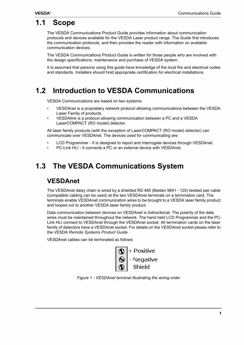
VESDAnet cables can be terminated as follows
Figure 1 - VESDAnet terminal illustrating the wiring order
Communications Guide VESDA®
2
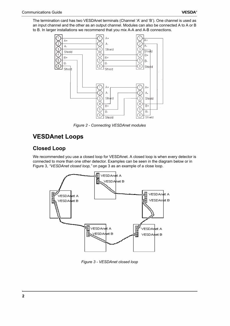
The termination card has two VESDAnet terminals (Channel ‘A’ and ‘B’). One channel is used as an input channel and the other as an output channel. Modules can also be connected A to A or B to B. In larger installations we recommend that you mix A-A and A-B connections.
Figure 2 - Connecting VESDAnet modules
VESDAnet Loops
Closed Loop We recommended you use a closed loop for VESDAnet. A closed loop is when every detector is connected to more than one other detector. Examples can be seen in the diagram below or in Figure 3, “VESDAnet closed loop,” on page 3 as an example of a close loop.
Figure 3 - VESDAnet closed loop
VESDA® Communications Guide
3
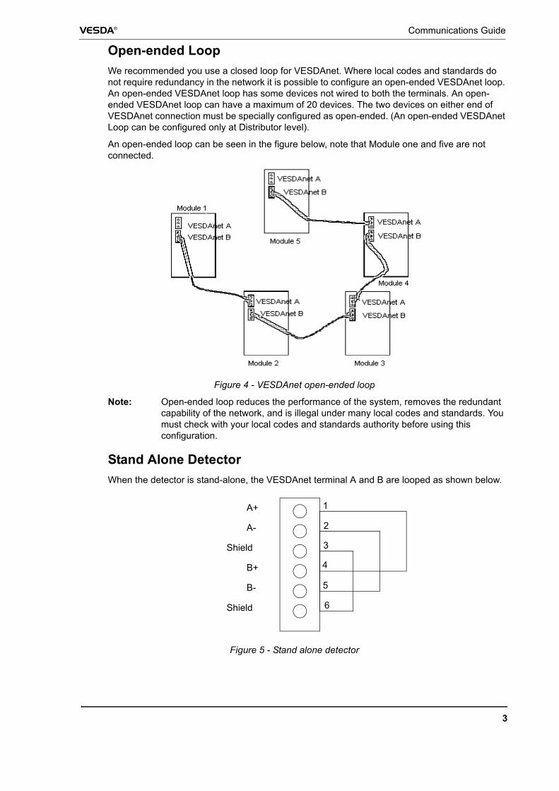
Open-ended Loop We recommended you use a closed loop for VESDAnet. Where local codes and standards do not require redundancy in the network it is possible to configure an open-ended VESDAnet loop. An open-ended VESDAnet loop has some devices not wired to both the terminals. An open-ended VESDAnet loop can have a maximum of 20 devices. The two devices on either end of VESDAnet connection must be specially configured as open-ended. (An open-ended VESDAnet Loop can be configured only at Distributor level).
An open-ended loop can be seen in the figure below, note that Module one and five are not connected.
Figure 4 - VESDAnet open-ended loop
Note: Open-ended loop reduces the performance of the system, removes the redundant capability of the network, and is illegal under many local codes and standards. You must check with your local codes and standards authority before using this configuration.
Stand Alone DetectorWhen the detector is stand-alone, the VESDAnet terminal A and B are looped as shown below.
Figure 5 - Stand alone detector
A+
A-
Shield
B+
B-
Shield
1
2
3
4
5
6
Communications Guide VESDA®
4
VESDAlink ProtocolVESDAlink is a protocol allowing communication between a PC and a VESDA LaserCOMPACT (RO model) Detector. A RS232 data cable connects a PC directly to the 9 pin VESDAlink programming socket.
1.4 Communication DevicesA number of different devices can be used to communicate and configure VESDAnet. Options include a VESDA LCD Programmer, or a PC Link HLI.
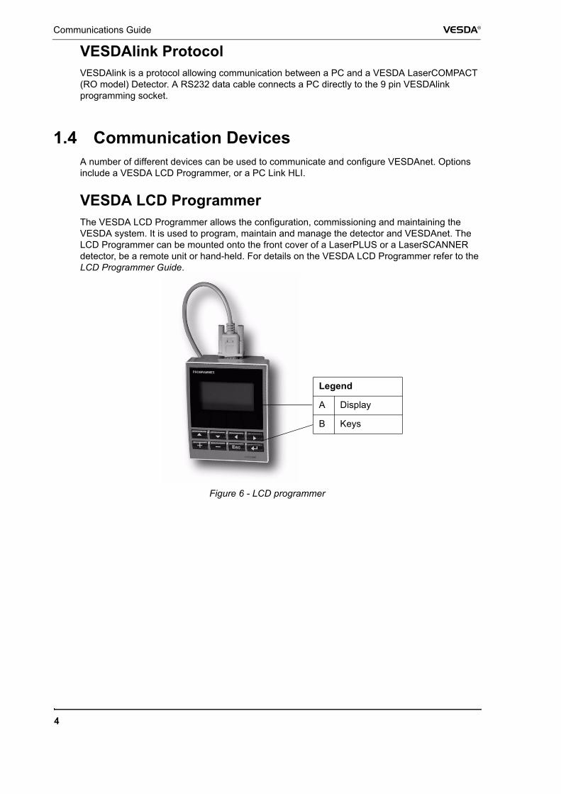
VESDA LCD ProgrammerThe VESDA LCD Programmer allows the configuration, commissioning and maintaining the VESDA system. It is used to program, maintain and manage the detector and VESDAnet. The LCD Programmer can be mounted onto the front cover of a LaserPLUS or a LaserSCANNER detector, be a remote unit or hand-held. For details on the VESDA LCD Programmer refer to the LCD Programmer Guide.
Figure 6 - LCD programmer
Legend
A Display
B Keys
VESDA® Communications Guide
5
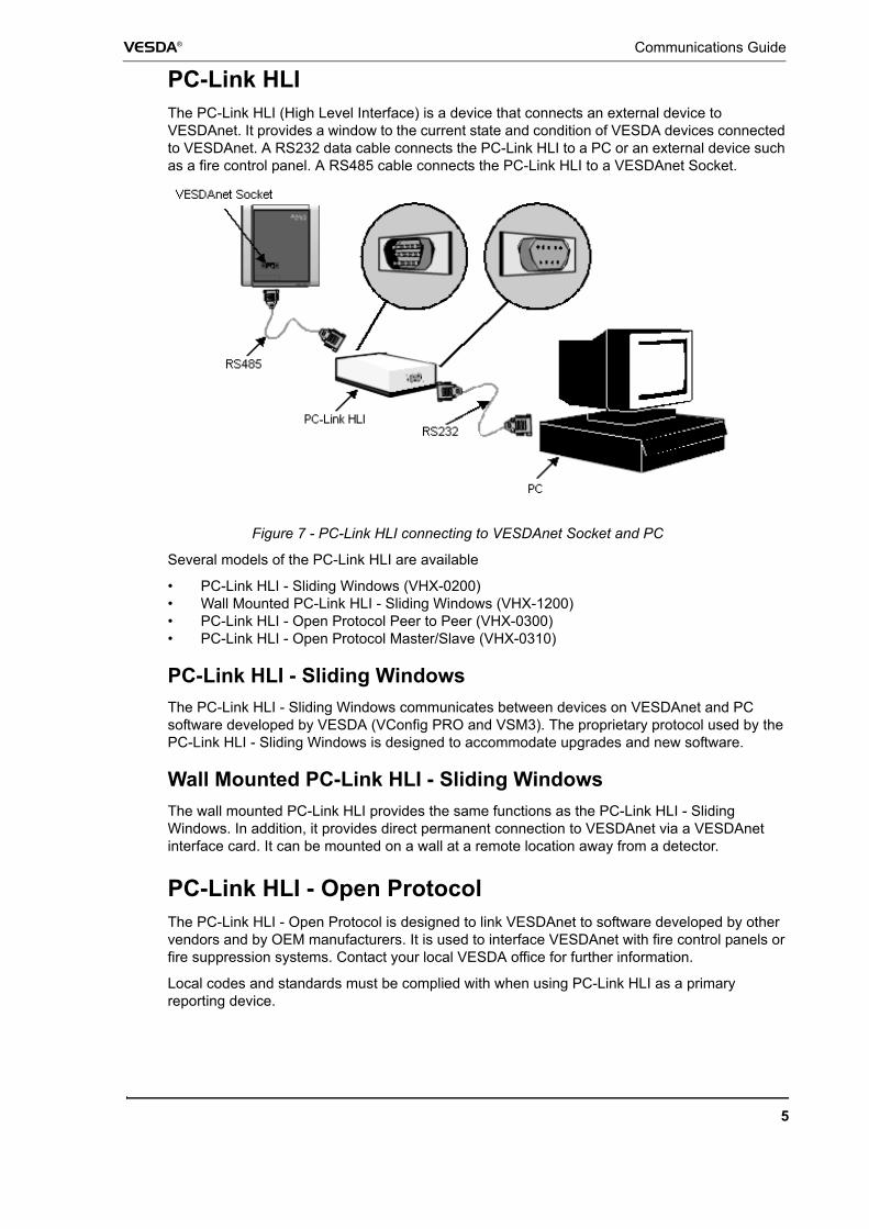
PC-Link HLIThe PC-Link HLI (High Level Interface) is a device that connects an external device to VESDAnet. It provides a window to the current state and condition of VESDA devices connected to VESDAnet. A RS232 data cable connects the PC-Link HLI to a PC or an external device such as a fire control panel. A RS485 cable connects the PC-Link HLI to a VESDAnet Socket.
Figure 7 - PC-Link HLI connecting to VESDAnet Socket and PC
Several models of the PC-Link HLI are available
• PC-Link HLI - Sliding Windows (VHX-0200)• Wall Mounted PC-Link HLI - Sliding Windows (VHX-1200)• PC-Link HLI - Open Protocol Peer to Peer (VHX-0300)• PC-Link HLI - Open Protocol Master/Slave (VHX-0310)
PC-Link HLI - Sliding WindowsThe PC-Link HLI - Sliding Windows communicates between devices on VESDAnet and PC software developed by VESDA (VConfig PRO and VSM3). The proprietary protocol used by the PC-Link HLI - Sliding Windows is designed to accommodate upgrades and new software.
Wall Mounted PC-Link HLI - Sliding Windows The wall mounted PC-Link HLI provides the same functions as the PC-Link HLI - Sliding Windows. In addition, it provides direct permanent connection to VESDAnet via a VESDAnet interface card. It can be mounted on a wall at a remote location away from a detector.
PC-Link HLI - Open Protocol The PC-Link HLI - Open Protocol is designed to link VESDAnet to software developed by other vendors and by OEM manufacturers. It is used to interface VESDAnet with fire control panels or fire suppression systems. Contact your local VESDA office for further information.
Local codes and standards must be complied with when using PC-Link HLI as a primary reporting device.
Communications Guide VESDA®
6
The PC-Link HLI - Open Protocol can operate in two modes:
Peer to Peer ModeThe VHX-0300 PC-Link HLI operates in the peer to peer mode. It reports the current VESDA Zone’s status in this mode. The PC-Link HLI can be configured to report on current airflow status, fault status and display status messages. Both the host and the HLI can initiate communication. The open protocol is capable of operating with the LaserSCANNER detector. It can report the first alarm sector and identify the sector in which this was raised. Large VESDAnet installations will generate excessive data transmission. To reduce the traffic to the minimum, unsolicited transmission of messages can be configured to allow only current address status messages.
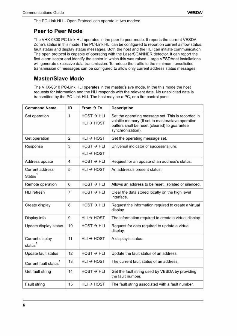
Master/Slave Mode The VHX-0310 PC-Link HLI operates in the master/slave mode. In the this mode the host requests for information and the HLI responds with the relevant data. No unsolicited data is transmitted by the PC-Link HLI. The host may be a PC, or a fire control panel.
Command Name ID From To Description
Set operation 1 HOST HLI
HLI HOST
Set the operating message set. This is recorded in volatile memory (If set to master/slave operation buffers shall be reset (cleared) to guarantee synchronization).
Get operation 2 HLI HOST Get the operating message set.
Response 3 HOST HLI
HLI HOST
Universal indicator of success/failure.
Address update 4 HOST HLI Request for an update of an address’s status.
Current address
Status15 HLI HOST An address’s present status.
Remote operation 6 HOST HLI Allows an address to be reset, isolated or silenced.
HLI refresh 7 HOST HLI Clear the data stored locally on the high level interface.
Create display 8 HOST HLI Request the information required to create a virtual display.
Display info 9 HLI HOST The information required to create a virtual display.
Update display status 10 HOST HLI Request for data required to update a virtual display.
Current display
status111 HLI HOST A display’s status.
Update fault status 12 HOST HLI Update the fault status of an address.
Current fault status1 13 HLI HOST The current fault status of an address.
Get fault string 14 HOST HLI Get the fault string used by VESDA by providing the fault number.
Fault string 15 HLI HOST The fault string associated with a fault number.
VESDA® Communications Guide
7
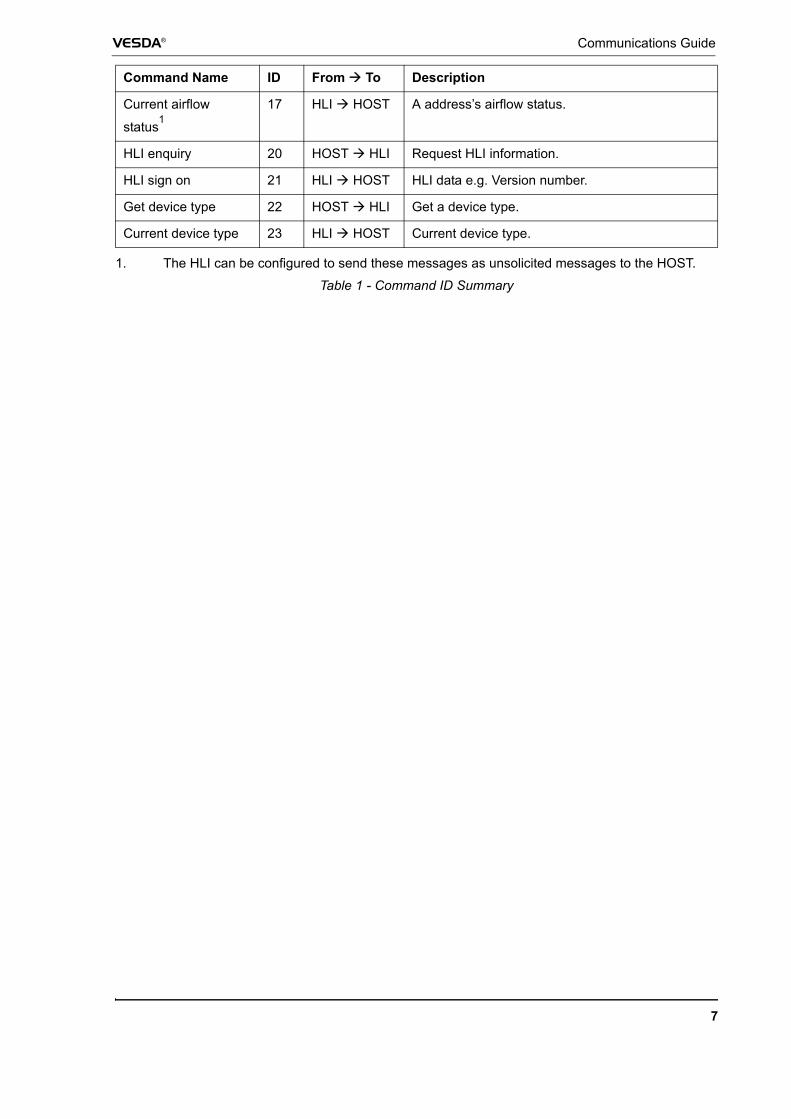
Current airflow
status117 HLI HOST A address’s airflow status.
HLI enquiry 20 HOST HLI Request HLI information.
HLI sign on 21 HLI HOST HLI data e.g. Version number.
Get device type 22 HOST HLI Get a device type.
Current device type 23 HLI HOST Current device type.
1. The HLI can be configured to send these messages as unsolicited messages to the HOST.
Table 1 - Command ID Summary
Command Name ID From To Description

Communications Guide VESDA®
8