Embed Size (px)
Citation preview
LISTED
52TL
IND.CONT. EQ.
E83849
GE Multilin's Quality Management System is
registered to ISO9001:2000
QMI # 005094
Digital EnergyMultilin
GE Multilin
215 Anderson Avenue, Markham, Ontario
Canada L6E 1B3
Tel: (905) 294-6222 Fax: (905) 201-2098
Internet: http://www.GEmultilin.com
MM200 revision: 1.2x
Manual P/N: 1601-9033-A4
GE publication code: GEK-113402C
Copyright © 2010 GE Multilin
IISO9001:2000GE MULT I L
I N
RE
GISTERED
*1601-9033-A4*
MM200Motor Management SystemCommunications Guide

© 2010 GE Multilin Incorporated. All rights reserved.
GE Multilin MM200 Motor Management System Communications Guide for revision 1.2x.
MM200 Motor Management System, EnerVista, EnerVista Launchpad, and EnerVista MM200 Setup are registered trademarks of GE Multilin Inc.
Allen-Bradley, RSLinx DeviceNet-3, RSNetWorx for DeviceNet, EDS Wizard, Allen-Bradley 1770-KFD Driver, and 1747-SDN Scanner Module, are registered trademarks of Rockwell Automation, Inc.
The contents of this manual are the property of GE Multilin Inc. This documentation is furnished on license and may not be reproduced in whole or in part without the permission of GE Multilin. The content of this manual is for informational use only and is subject to change without notice.
Part number: 1601-9033-A4 (September 2010)

MM200 MOTOR MANAGEMENT SYSTEM – COMMUNICATIONS GUIDE i
Table of Contents
Communications interfaces ....................................................................................................... 1RS485 interface (Modbus RTU) .................................................................................................. 2
Modbus Protocol ...................................................................................................................................... 2Electrical Interface ................................................................................................................................. 2Data Frame Format and Data Rate ............................................................................................... 2Data Packet Format .............................................................................................................................. 2Error Checking .......................................................................................................................................... 3CRC-16 Algorithm ................................................................................................................................... 3Timing ........................................................................................................................................................... 4MM200 supported functions ............................................................................................................. 4
Modbus Functions .................................................................................................................................. 4Function Code 03H ................................................................................................................................ 4Function Code 04H ................................................................................................................................ 5Function Code 05H ................................................................................................................................ 6Function Code 06H ................................................................................................................................ 7Function Code 07H ................................................................................................................................ 7Function Code 08H ................................................................................................................................ 8Function Code 10H ................................................................................................................................ 8Error Responses ...................................................................................................................................... 9
Modbus memory map ....................................................................................................................... 10Format codes ......................................................................................................................................... 19Performing Commands Using Function Code 10H .............................................................. 24
Using the User Definable Memory Map .....................................................................................25Fieldbus interface .........................................................................................................................26
Profibus DP .............................................................................................................................................. 26Profibus power supply configuration ..........................................................................................27Profibus termination ...........................................................................................................................28Profibus DP-parameterization ........................................................................................................28Profibus DP-configuration ................................................................................................................28Profibus Input Data ..............................................................................................................................31Profibus Output Data ..........................................................................................................................31Profibus DPV0-Diagnostics ..............................................................................................................32
Profibus DPV1 ........................................................................................................................................ 40Profibus DPV1-Acyclic read/write data ......................................................................................40Profibus DPV1-Diagnostics ..............................................................................................................42
DeviceNet protocol .............................................................................................................................. 50DeviceNet power supply configuration ......................................................................................50DeviceNet setup and configuration (typical) ...........................................................................51DeviceNet setup and configuration (ADR) .................................................................................66DeviceNet Communications ............................................................................................................69Poll data ....................................................................................................................................................69Identity Object (Class Code 01H) ...................................................................................................70Message Router (Class Code 02H) ................................................................................................70DeviceNet Object (Class Code 03H) ..............................................................................................71DeviceNet Connection Object (Class Code 05H) ....................................................................71DeviceNet Motor Data - Explicit Object (Class Code A0H) .................................................72DeviceNet Motor Data - Explicit Object (Class Code A1H) .................................................74DeviceNet Motor Analog Data - Explicit Object (Class Code A2H) .................................77DeviceNet - Explicit Motor Analog Data Object, Class Code B0H, Services ..............78DeviceNet - Explicit Motor Object, Class Code B1H ..............................................................80
Change notes ..................................................................................................................................81Revision history ..................................................................................................................................... 81

ii MM200 MOTOR MANAGEMENT SYSTEM – COMMUNICATIONS GUIDE
MM200 MOTOR MANAGEMENT SYSTEM – COMMUNICATIONS GUIDE 1
MM200 Motor Management System
Communications Guide
Digital EnergyMultilin
Communications Guide
Communications interfaces
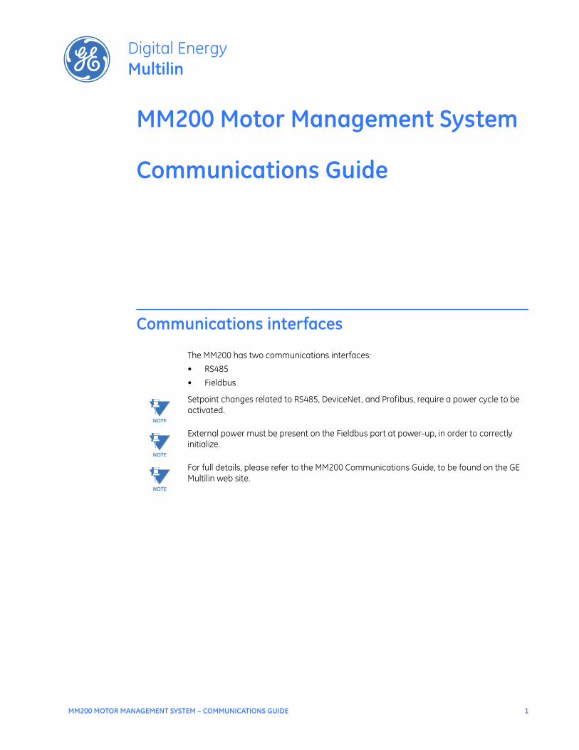
The MM200 has two communications interfaces:• RS485• Fieldbus
NOTE
NOTE: Setpoint changes related to RS485, DeviceNet, and Profibus, require a power cycle to be activated.
NOTE
NOTE: External power must be present on the Fieldbus port at power-up, in order to correctly initialize.
NOTE
NOTE: For full details, please refer to the MM200 Communications Guide, to be found on the GE Multilin web site.

2 MM200 MOTOR MANAGEMENT SYSTEM – COMMUNICATIONS GUIDE
RS485 INTERFACE (MODBUS RTU) COMMUNICATIONS GUIDE
RS485 interface (Modbus RTU)
The RS485 interface is a serial two-wire port intended for use as a Modbus RTU slave. The RS485 port has the following characteristics.• Address: 1 to 254• Baud rate: 9600 to 115200 bps• Supported Modbus function codes: 3, 4, 5, 6, 7, 8, 16
Modbus ProtocolThe MM200 implements a subset of the Modicon Modbus RTU serial communication standard. The Modbus protocol is hardware-independent. That is, the physical layer can be any of a variety of standard hardware configurations. This includes RS232, RS422, RS485, fibre optics, etc. Modbus is a single master / multiple slave type of protocol suitable for a multi-drop configuration as provided by RS485 hardware. The MM200 Modbus implementation employs two-wire RS485 hardware. Using RS485, up to 32 MM200s can be daisy-chained together on a single communication channel.The MM200 is always a Modbus slave. It can not be programmed as a Modbus master. Computers or PLCs are commonly programmed as masters. Both monitoring and control are possible using read and write register commands. Other commands are supported to provide additional functions.
Electrical Interface The hardware or electrical interface in the MM200 is two-wire RS485. In a two-wire link, data is transmitted and received over the same two wires. Although RS485 two wire communication is bi-directional, the data is never transmitted and received at the same time. This means that the data flow is half duplex.RS485 lines should be connected in a daisy chain configuration with terminating networks installed at each end of the link (i.e. at the master end and at the slave farthest from the master). The terminating network should consist of a 120 W resistor in series with a 1 nF ceramic capacitor when used with Belden 9841 RS485 wire. Shielded wire should always be used to minimize noise. The shield should be connected to all of the MM200s as well as the master, then grounded at one location only. This keeps the ground potential at the same level for all of the devices on the serial link.
NOTE
NOTE: Polarity is important in RS485 communications. The '+' (positive) terminals of every device must be connected together.
Data Frame Formatand Data Rate
One data frame of an asynchronous transmission to or from a MM200 typically consists of 1 start bit , 8 data bits, and 1 stop bit. This produces a 10 bit data frame. This is important for transmission through modems at high bit rates (11 bit data frames are not supported by Hayes modems at bit rates of greater than 300 bps).Modbus protocol can be implemented at any standard communication speed. The MM200 supports operation at 9600, 19200, 38400, 57600, and 115200 baud.
Data Packet Format A complete request/response sequence consists of the following bytes (transmitted as separate data frames): Master Request Transmission:
SLAVE ADDRESS: 1 byte FUNCTION CODE: 1 byteDATA: variable number of bytes depending on FUNCTION CODECRC: 2 bytes
COMMUNICATIONS GUIDE RS485 INTERFACE (MODBUS RTU)
MM200 MOTOR MANAGEMENT SYSTEM – COMMUNICATIONS GUIDE 3
Slave Response Transmission: SLAVE ADDRESS: 1 byteFUNCTION CODE: 1 byteDATA: variable number of bytes depending on FUNCTION CODECRC: 2 bytes
SLAVE ADDRESS: This is the first byte of every transmission. This byte represents the user-assigned address of the slave device that is to receive the message sent by the master. Each slave device must be assigned a unique address and only the addressed slave will respond to a transmission that starts with its address. In a master request transmission the SLAVE ADDRESS represents the address of the slave to which the request is being sent. In a slave response transmission the SLAVE ADDRESS represents the address of the slave that is sending the response. FUNCTION CODE: This is the second byte of every transmission. Modbus defines function codes of 1 to 127. DATA: This will be a variable number of bytes depending on the FUNCTION CODE. This may be Actual Values, Setpoints, or addresses sent by the master to the slave or by the slave to the master. CRC: This is a two byte error checking code.
Error Checking The RTU version of Modbus includes a two byte CRC-16 (16 bit cyclic redundancy check) with every transmission. The CRC-16 algorithm essentially treats the entire data stream (data bits only; start, stop and parity ignored) as one continuous binary number. This number is first shifted left 16 bits and then divided by a characteristic polynomial (11000000000000101B). The 16 bit remainder of the division is appended to the end of the transmission, MSByte first. The resulting message including CRC, when divided by the same polynomial at the receiver will give a zero remainder if no transmission errors have occurred. If a MM200 Modbus slave device receives a transmission in which an error is indicated by the CRC-16 calculation, the slave device will not respond to the transmission. A CRC-16 error indicates than one or more bytes of the transmission were received incorrectly and thus the entire transmission should be ignored in order to avoid the MM200 performing any incorrect operation. The CRC-16 calculation is an industry standard method used for error detection. An algorithm is included here to assist programmers in situations where no standard CRC-16 calculation routines are available.
CRC-16 Algorithm Once the following algorithm is complete, the working register “A” will contain the CRC value to be transmitted. Note that this algorithm requires the characteristic polynomial to be reverse bit ordered. The MSBit of the characteristic polynomial is dropped since it does not affect the value of the remainder. The following symbols are used in the algorithm:—>: data transferA: 16 bit working registerAL: low order byte of AAH: high order byte of ACRC: 16 bit CRC-16 valuei, j: loop counters(+): logical exclusive or operatorDi: i-th data byte (i = 0 to N-1)G: 16 bit characteristic polynomial = 1010000000000001 with MSbit dropped and bit order reversedshr(x): shift right (the LSbit of the low order byte of x shifts into a carry flag, a '0' is shifted into the MSbit of the high order byte of x, all other bits shift right one location
4 MM200 MOTOR MANAGEMENT SYSTEM – COMMUNICATIONS GUIDE
RS485 INTERFACE (MODBUS RTU) COMMUNICATIONS GUIDE
The algorithm is:
1. FFFF hex —> A
2. 0 —> i
3. 0 —> j
4. Di (+) AL —> AL
5. j+1 —> j
6. shr(A)
7. is there a carry? No: go to 8. Yes: G (+) A —> A
8. is j = 8? No: go to 5. Yes: go to 9.
9. i+1 —> i
10. is i = N? No: go to 3. Yes: go to 11.
11. A —> CRC
Timing Data packet synchronization is maintained by timing constraints. The receiving device must measure the time between the reception of characters. If 3.5 character times elapse without a new character or completion of the packet, then the communication link must be reset (i.e. all slaves start listening for a new transmission from the master). Thus at 9600 baud a delay of greater than 3.5 x 1 / 9600 x 10 x = x 3.65 x ms will cause the communication link to be reset.
MM200 supportedfunctions
The following functions are supported by the MM200: • FUNCTION CODE 03 - Read Setpoints and Actual Values • FUNCTION CODE 04 - Read Setpoints and Actual Values • FUNCTION CODE 05 - Execute Operation • FUNCTION CODE 06 - Store Single Setpoint • FUNCTION CODE 07 - Read Device Status • FUNCTION CODE 08 - Loopback Test • FUNCTION CODE 10 - Store Multiple Setpoints
Modbus Functions
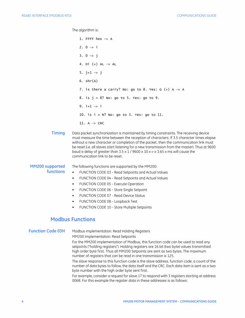
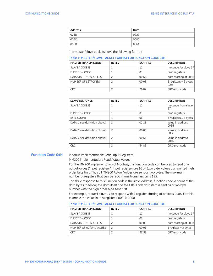
Function Code 03H Modbus implementation: Read Holding RegistersMM200 implementation: Read SetpointsFor the MM200 implementation of Modbus, this function code can be used to read any setpoints (“holding registers”). Holding registers are 16 bit (two byte) values transmitted high order byte first. Thus all MM200 Setpoints are sent as two bytes. The maximum number of registers that can be read in one transmission is 125.The slave response to this function code is the slave address, function code, a count of the number of data bytes to follow, the data itself and the CRC. Each data item is sent as a two byte number with the high order byte sent first.For example, consider a request for slave 17 to respond with 3 registers starting at address 006B. For this example the register data in these addresses is as follows:
COMMUNICATIONS GUIDE RS485 INTERFACE (MODBUS RTU)
MM200 MOTOR MANAGEMENT SYSTEM – COMMUNICATIONS GUIDE 5
The master/slave packets have the following format:
Table 1: MASTER/SLAVE PACKET FORMAT FOR FUNCTION CODE 03H
Function Code 04H Modbus Implementation: Read Input Registers MM200 implementation: Read Actual Values For the MM200 implementation of Modbus, this function code can be used to read any actual values (“input registers”). Input registers are 16 bit (two byte) values transmitted high order byte first. Thus all MM200 Actual Values are sent as two bytes. The maximum number of registers that can be read in one transmission is 125.The slave response to this function code is the slave address, function code, a count of the data bytes to follow, the data itself and the CRC. Each data item is sent as a two byte number with the high order byte sent first. For example, request slave 17 to respond with 1 register starting at address 0008. For this example the value in this register (0008) is 0000.
Table 2: MASTER/SLAVE PACKET FORMAT FOR FUNCTION CODE 04H
Address Data
006B 022B
006C 0000
006D 0064
MASTER TRANSMISSION BYTES EXAMPLE DESCRIPTION
SLAVE ADDRESS 1 11 message for slave 17
FUNCTION CODE 1 03 read registers
DATA STARTING ADDRESS 2 00 6B data starting at 006B
NUMBER OF SETPOINTS 2 00 03 3 registers = 6 bytes total
CRC 2 76 87 CRC error code
SLAVE RESPONSE BYTES EXAMPLE DESCRIPTION
SLAVE ADDRESS 1 11 message from slave 17
FUNCTION CODE 1 03 read registers
BYTE COUNT 1 06 3 registers = 6 bytes
DATA 1 (see definition above) 2 02 2B value in address 006B
DATA 2 (see definition above) 2 00 00 value in address 006C
DATA 3 (see definition above) 2 00 64 value in address 006D
CRC 2 54 83 CRC error code
MASTER TRANSMISSION BYTES EXAMPLE DESCRIPTION
SLAVE ADDRESS 1 11 message for slave 17
FUNCTION CODE 1 04 read registers
DATA STARTING ADDRESS 2 00 08 data starting at 0008
NUMBER OF ACTUAL VALUES 2 00 01 1 register = 2 bytes
CRC 2 B2 98 CRC error code

6 MM200 MOTOR MANAGEMENT SYSTEM – COMMUNICATIONS GUIDE
RS485 INTERFACE (MODBUS RTU) COMMUNICATIONS GUIDE
Function Code 05H Modbus Implementation: Force Single CoilMM200 Implementation: Execute OperationThis function code allows the master to request a MM200 to perform specific command operations.For example, to request slave 17 to execute operation code 1 (reset), we have the following master/slave packet format:
Table 3: MASTER/SLAVE PACKET FORMAT FOR FUNCTION CODE 05H
The commands that can be performed by the MM200 using function code 05 can also be initiated by using function code 16.
SLAVE RESPONSE BYTES EXAMPLE DESCRIPTION
SLAVE ADDRESS 1 11 message from slave 17
FUNCTION CODE 1 04 read registers
BYTE COUNT 1 02 1 register = 2 bytes
DATA (see definition above) 2 00 00 value in address 0008
CRC 2 78 F3 CRC error code
MASTER TRANSMISSION BYTES EXAMPLE DESCRIPTION
SLAVE ADDRESS 1 11 message for slave 17
FUNCTION CODE 1 05 execute operation
OPERATION CODE 2 00 01 operation code 1
CODE VALUE 2 FF 00 perform function
CRC 2 DF 6A CRC error code
SLAVE RESPONSE BYTES EXAMPLE DESCRIPTION
SLAVE ADDRESS 1 11 message from slave 17
FUNCTION CODE 1 05 execute operation
OPERATION CODE 2 00 01 operation code 1
CODE VALUE 2 FF 00 perform function
CRC 2 DF 6A CRC error code
Operation Code Description
1 Reset
2 Lockout Reset
3 Stop
4 Start A
5 Start B
96 Clear Last Trip Data Prompt
99 Clear Counters
102 Clear Maintenance Timer
113 Reset Motor Information
114 Auto Mode
115 Manual Mode
COMMUNICATIONS GUIDE RS485 INTERFACE (MODBUS RTU)
MM200 MOTOR MANAGEMENT SYSTEM – COMMUNICATIONS GUIDE 7
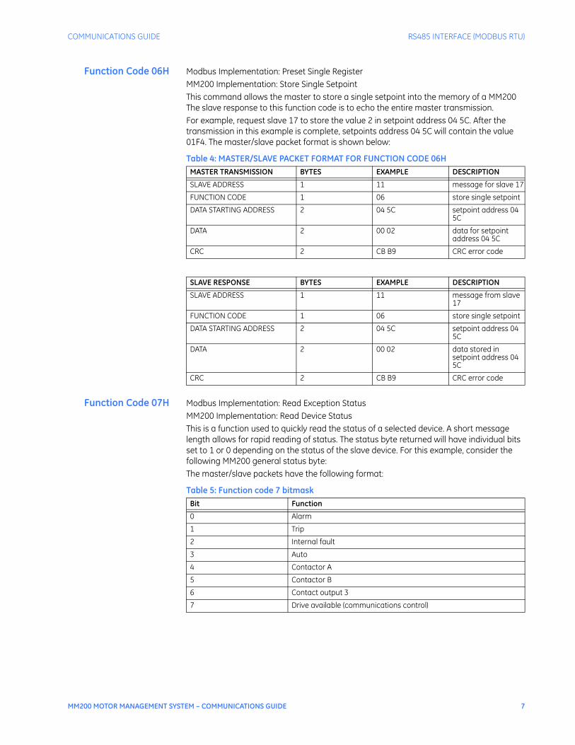
Function Code 06H Modbus Implementation: Preset Single Register MM200 Implementation: Store Single Setpoint This command allows the master to store a single setpoint into the memory of a MM200 The slave response to this function code is to echo the entire master transmission. For example, request slave 17 to store the value 2 in setpoint address 04 5C. After the transmission in this example is complete, setpoints address 04 5C will contain the value 01F4. The master/slave packet format is shown below:
Table 4: MASTER/SLAVE PACKET FORMAT FOR FUNCTION CODE 06H
Function Code 07H Modbus Implementation: Read Exception StatusMM200 Implementation: Read Device StatusThis is a function used to quickly read the status of a selected device. A short message length allows for rapid reading of status. The status byte returned will have individual bits set to 1 or 0 depending on the status of the slave device. For this example, consider the following MM200 general status byte:The master/slave packets have the following format:
Table 5: Function code 7 bitmask
MASTER TRANSMISSION BYTES EXAMPLE DESCRIPTION
SLAVE ADDRESS 1 11 message for slave 17
FUNCTION CODE 1 06 store single setpoint
DATA STARTING ADDRESS 2 04 5C setpoint address 04 5C
DATA 2 00 02 data for setpoint address 04 5C
CRC 2 CB B9 CRC error code
SLAVE RESPONSE BYTES EXAMPLE DESCRIPTION
SLAVE ADDRESS 1 11 message from slave 17
FUNCTION CODE 1 06 store single setpoint
DATA STARTING ADDRESS 2 04 5C setpoint address 04 5C
DATA 2 00 02 data stored in setpoint address 04 5C
CRC 2 CB B9 CRC error code
Bit Function
0 Alarm
1 Trip
2 Internal fault
3 Auto
4 Contactor A
5 Contactor B
6 Contact output 3
7 Drive available (communications control)

8 MM200 MOTOR MANAGEMENT SYSTEM – COMMUNICATIONS GUIDE
RS485 INTERFACE (MODBUS RTU) COMMUNICATIONS GUIDE
Table 6: MASTER/SLAVE PACKET FORMAT FOR FUNCTION CODE 07H
Function Code 08H Modbus Implementation: Loopback Test MM200 Implementation: Loopback Test This function is used to test the integrity of the communication link. The MM200 will echo the request. For example, consider a loopback test from slave 17:
Table 7: MASTER/SLAVE PACKET FORMAT FOR FUNCTION CODE 08H
Function Code 10H Modbus Implementation: Preset Multiple RegistersMM200 Implementation: Store Multiple SetpointsThis function code allows multiple Setpoints to be stored into the MM200 memory. Modbus “registers” are 16-bit (two byte) values transmitted high order byte first. Thus all MM200 setpoints are sent as two bytes. The maximum number of Setpoints that can be stored in one transmission is dependent on the slave device. Modbus allows up to a maximum of 60 holding registers to be stored. The MM200 response to this function code is to echo the slave address, function code, starting address, the number of Setpoints stored, and the CRC.For example, consider a request for slave 17 to store the value 00 02 to setpoint address 04 5C and the value 01 F4 to setpoint address 04 5D. After the transmission in this example is complete, MM200 slave 17 will have the following setpoints information stored:
MASTER TRANSMISSION BYTES EXAMPLE DESCRIPTION
SLAVE ADDRESS 1 11 message for slave 17
FUNCTION CODE 1 07 read device status
CRC 2 4C 22 CRC error code
SLAVE RESPONSE BYTES EXAMPLE DESCRIPTION
SLAVE ADDRESS 1 11 message from slave 17
FUNCTION CODE 1 07 read device status
DEVICE STATUS (see definition above)
1 2C status = 00101100 (in binary)
CRC 2 22 28 CRC error code
MASTER TRANSMISSION BYTES EXAMPLE DESCRIPTION
SLAVE ADDRESS 1 11 message for slave 17
FUNCTION CODE 1 08 loopback test
DIAG CODE 2 00 00 must be 00 00
DATA 2 00 00 must be 00 00
CRC 2 E0 0B CRC error code
SLAVE RESPONSE BYTES EXAMPLE DESCRIPTION
SLAVE ADDRESS 1 11 message from slave 17
FUNCTION CODE 1 08 loopback test
DIAG CODE 2 00 00 must be 00 00
DATA 2 00 00 must be 00 00
CRC 2 E0 0B CRC error code

COMMUNICATIONS GUIDE RS485 INTERFACE (MODBUS RTU)
MM200 MOTOR MANAGEMENT SYSTEM – COMMUNICATIONS GUIDE 9
The master/slave packets have the following format:
Table 8: MASTER/SLAVE PACKET FORMAT FOR FUNCTION CODE 10H
Error Responses When a MM200 detects an error other than a CRC error, a response will be sent to the master. The MSBit of the FUNCTION CODE byte will be set to 1 (i.e. the function code sent from the slave will be equal to the function code sent from the master plus 128). The following byte will be an exception code indicating the type of error that occurred. Transmissions received from the master with CRC errors will be ignored by the MM200. The slave response to an error (other than CRC error) will be: SLAVE ADDRESS: 1 byte FUNCTION CODE: 1 byte (with MSbit set to 1) EXCEPTION CODE: 1 byte CRC: 2 bytes The MM200 implements the following exception response codes:
01 - ILLEGAL FUNCTIONThe function code transmitted is not one of the functions supported by the MM200.
02 - ILLEGAL DATA ADDRESSThe address referenced in the data field transmitted by the master is not an allowable address for the MM200.
03 - ILLEGAL DATA VALUE The value referenced in the data field transmitted by the master is not within range for the selected data address.
Address Data
04 5C 00 02
04 5D 01 F4
MASTER TRANSMISSION BYTES EXAMPLE DESCRIPTION
SLAVE ADDRESS 1 11 message for slave 17
FUNCTION CODE 1 10 store setpoints
DATA STARTING ADDRESS 2 04 5C setpoint address 04 5C
NUMBER OF SETPOINTS 2 00 02 2 setpoints = 4 bytes total
BYTE COUNT 1 04 4 bytes of data
DATA 1 2 00 02 data for setpoint address 04 5C
DATA 2 2 01 F4 data for setpoint address 04 5D
CRC 2 31 11 CRC error code
SLAVE RESPONSE BYTES EXAMPLE DESCRIPTION
SLAVE ADDRESS 1 11 message from slave 17
FUNCTION CODE 1 10 store setpoints
DATA STARTING ADDRESS 2 04 5C setpoint address 04 5C
NUMBER OF SETPOINTS 2 00 02 2 setpoints
CRC 2 82 7A CRC error code
10 MM200 MOTOR MANAGEMENT SYSTEM – COMMUNICATIONS GUIDE
RS485 INTERFACE (MODBUS RTU) COMMUNICATIONS GUIDE
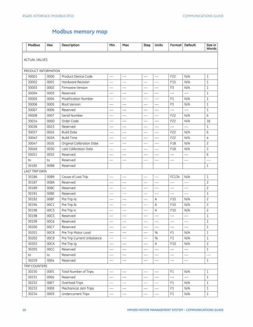
Modbus memory map
Modbus Hex Description Min Max Step Units Format Default Size in Words
ACTUAL VALUES
PRODUCT INFORMATION
30001 0000 Product Device Code --- --- --- --- F22 N/A 1
30002 0001 Hardware Revision --- --- --- --- F15 N/A 1
30003 0002 Firmware Version --- --- --- --- F3 N/A 1
30004 0003 Reserved --- --- --- --- --- --- 1
30005 0004 Modification Number --- --- --- --- F1 N/A 1
30006 0005 Boot Version --- --- --- --- F3 N/A 1
30007 0006 Reserved --- --- --- --- --- --- 1
30008 0007 Serial Number --- --- --- --- F22 N/A 6
30014 000D Order Code --- --- --- --- F22 N/A 16
30036 0023 Reserved --- --- --- --- --- --- 1
30037 0024 Build Date --- --- --- --- F22 N/A 6
30043 002A Build Time --- --- --- --- F22 N/A 4
30047 002E Original Calibration Date --- --- --- --- F18 N/A 2
30049 0030 Last Calibration Date --- --- --- --- F18 N/A 2
30051 0032 Reserved --- --- --- --- --- --- 6
to to Reserved --- --- --- --- --- --- ---
30185 00B8 Reserved 1
LAST TRIP DATA
30186 00B9 Cause of Last Trip --- --- --- --- FC134 N/A 1
30187 00BA Reserved --- --- --- --- --- --- 2
30189 00BC Reserved --- --- --- --- --- --- 2
30191 00BE Reserved --- --- --- --- --- --- 1
30192 00BF Pre Trip Ia --- --- --- A F10 N/A 2
30194 00C1 Pre Trip Ib --- --- --- A F10 N/A 2
30196 00C3 Pre Trip Ic --- --- --- A F10 N/A 2
30198 00C5 Reserved --- --- --- --- --- --- 1
30199 00C6 Reserved --- --- --- --- --- --- 1
30200 00C7 Reserved --- --- --- --- --- --- 1
30201 00C8 Pre Trip Motor Load --- --- --- % F1 N/A 1
30202 00C9 Pre Trip Current Unbalance --- --- --- % F1 N/A 1
30203 00CA Pre Trip Ig --- --- --- A F10 N/A 2
30205 00CC Reserved --- --- --- --- --- --- 1
to to Reserved --- --- --- --- --- --- ---
30229 00E4 Reserved --- --- --- --- --- --- 1
TRIP COUNTERS
30230 00E5 Total Number of Trips --- --- --- --- F1 N/A 1
30231 00E6 Reserved --- --- --- --- --- --- 1
30232 00E7 Overload Trips --- --- --- --- F1 N/A 1
30233 00E8 Mechanical Jam Trips --- --- --- --- F1 N/A 1
30234 00E9 Undercurrent Trips --- --- --- --- F1 N/A 1

COMMUNICATIONS GUIDE RS485 INTERFACE (MODBUS RTU)
MM200 MOTOR MANAGEMENT SYSTEM – COMMUNICATIONS GUIDE 11
30235 00EA Current Unbalance Trips --- --- --- --- F1 N/A 1
30236 00EB Ground Fault Trips --- --- --- --- F1 N/A 1
30237 00EC Motor Acceleration Trips --- --- --- --- F1 N/A 1
30238 00ED Reserved --- --- --- --- --- --- 1
to to Reserved --- --- --- --- --- --- ---
30256 00FF Reserved --- --- --- --- --- --- 1
GENERAL TIMERS
30257 0100 Number of Motor Starts --- --- --- --- F1 N/A 1
30258 0101 Reserved --- --- --- --- --- --- 1
30259 0102 Motor Running Hours --- --- --- hrs F9 N/A 2
30261 0104 Reserved --- --- --- --- --- --- 1
to to Reserved --- --- --- --- --- --- ---
30269 010C Reserved --- --- --- --- --- --- 1
START BLOCKS
30270 010D Overload Lockout --- --- --- --- F1 N/A 1
30271 010E Reserved --- --- --- --- --- --- 1
30272 010F Reserved --- --- --- --- --- --- 1
30273 0110 Restart Block --- --- --- s F1 N/A 1
30274 0111 Reserved --- --- --- --- --- --- 1
to to Reserved --- --- --- --- --- --- ---
30282 0119 Reserved --- --- --- --- --- --- 1
CONTACT/VIRTUAL INPUTS/OUTPUTS STATUS
30283 011A Reserved --- --- --- --- --- --- 2
30285 011C Contact Input 7-1 (Bit Field) --- --- --- --- FC167 N/A 2
30287 011E Reserved --- --- --- --- --- --- 1
to to Reserved --- --- --- --- --- --- ---
30297 0128 Reserved --- --- --- --- --- --- 1
30298 0129 Contact Output 3-1 (Bit Field) --- --- --- --- FC167 N/A 2
30300 012B Reserved --- --- --- --- --- --- 1
30301 012C Reserved --- --- --- --- --- --- 1
SECURITY
30302 012D Current Security Access Level --- --- --- --- F1 N/A 1
30303 012E Reserved --- --- --- --- --- --- 1
30304 012F Reserved --- --- --- --- --- --- 1
STATUS - MOTOR
30305 0130 Motor Status --- --- --- --- FC129 N/A 1
30306 0131 Extended Status --- --- --- --- FC178 N/A 1
30307 0132 Thermal Cap Used --- --- --- % F1 N/A 1
30308 0133 Time to Overload Trip --- --- --- s F20 N/A 2
30310 0135 Drive Status --- --- --- --- FC143 N/A 1
30311 0136 Reserved --- --- --- --- --- --- 1
30312 0137 Command Status --- --- --- --- FC128 N/A 1
30313 0138 Reserved --- --- --- --- --- --- 1
30314 0139 Reserved --- --- --- --- --- --- 1
to to Reserved --- --- --- --- --- --- ---
30327 0146 Reserved 1
Modbus Hex Description Min Max Step Units Format Default Size in Words

12 MM200 MOTOR MANAGEMENT SYSTEM – COMMUNICATIONS GUIDE
RS485 INTERFACE (MODBUS RTU) COMMUNICATIONS GUIDE
CURRENT METERING
30328 0147 Ia --- --- --- A F10 N/A 2
30330 0149 Ib --- --- --- A F10 N/A 2
30332 014B Ic --- --- --- A F10 N/A 2
30334 014D Iavg --- --- --- A F10 N/A 2
30336 014F Motor Load --- --- --- % F1 N/A 1
30337 0150 Current Unbalance --- --- --- %Ub F1 N/A 1
30338 0151 Ig --- --- --- A F10 N/A 2
30340 0153 Reserved --- --- --- --- --- --- 1
to to Reserved --- --- --- --- --- --- ---
30434 01B1 Reserved --- --- --- --- --- --- 1
TEMPERATURE METERING
30435 01B2 Thermistor --- --- --- ohms F1 N/A 1
30436 01B3 Reserved --- --- --- --- --- --- 1
to to Reserved --- --- --- --- --- --- ---
30466 01D1 Reserved 1
MOTOR STARTING LEARNED DATA
30467 01D2 Learned Acceleration Time --- --- --- s F2 N/A 1
30468 01D3 Learned Starting Current --- --- --- A F10 N/A 2
30470 01D5 Learned Starting Capacity --- --- --- % F1 N/A 1
30471 01D6 Reserved --- --- --- --- --- --- 1
to to Reserved --- --- --- --- --- --- ---
30504 01F7 Reserved --- --- --- --- --- --- 1
LED STATUS FOR GRAPHICAL AND BASIC CONTROL PANEL
30505 01F8 LED Status --- --- --- --- FC144 N/A 2
30507 01FA Reserved --- --- --- --- --- --- 1
to to Reserved --- --- --- --- --- --- ---
30523 020A Reserved --- --- --- --- --- --- 1
USER MAP VALUES
30524 020B User Map Value 1 --- --- --- --- F1 N/A 1
30525 020C User Map Value 2 --- --- --- --- F1 N/A 1
30526 020D User Map Value 3 --- --- --- --- F1 N/A 1
30527 020E User Map Value 4 --- --- --- --- F1 N/A 1
to to Reserved --- --- --- --- --- --- ---
30645 0284 User Map Value 122 --- --- --- --- F1 N/A 1
30646 0285 User Map Value 123 --- --- --- --- F1 N/A 1
30647 0286 User Map Value 124 --- --- --- --- F1 N/A 1
30648 0287 User Map Value 125 --- --- --- --- F1 N/A 1
30649 0288 Reserved --- --- --- --- --- --- 1
to to Reserved --- --- --- --- --- --- ---
30656 028F Reserved --- --- --- --- --- --- 1
SELF TEST
30657 0290 Internal Fault Cause --- --- --- --- FC188 N/A 2
30659 0292 Reserved --- --- --- --- --- --- 2
to to Reserved --- --- --- --- --- --- ---
30951 03B6 Reserved 1
Modbus Hex Description Min Max Step Units Format Default Size in Words
COMMUNICATIONS GUIDE RS485 INTERFACE (MODBUS RTU)
MM200 MOTOR MANAGEMENT SYSTEM – COMMUNICATIONS GUIDE 13
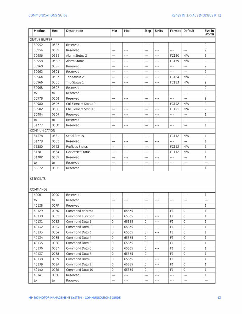
STATUS BUFFER
30952 03B7 Reserved --- --- --- --- --- --- 2
30954 03B9 Reserved --- --- --- --- --- --- 2
30956 03BB Alarm Status 2 --- --- --- --- FC180 N/A 2
30958 03BD Alarm Status 1 --- --- --- --- FC179 N/A 2
30960 03BF Reserved --- --- --- --- --- --- 2
30962 03C1 Reserved --- --- --- --- --- --- 2
30964 03C3 Trip Status 2 --- --- --- --- FC184 N/A 2
30966 03C5 Trip Status 1 --- --- --- --- FC183 N/A 2
30968 03C7 Reserved --- --- --- --- --- --- 2
to to Reserved --- --- --- --- --- --- ---
30978 03D1 Reserved --- --- --- --- --- --- 2
30980 03D3 Ctrl Element Status 2 --- --- --- --- FC192 N/A 2
30982 03D5 Ctrl Element Status 1 --- --- --- --- FC191 N/A 2
30984 03D7 Reserved --- --- --- --- --- --- 1
to to Reserved --- --- --- --- --- --- ---
31377 0560 Reserved --- --- --- --- --- --- 1
COMMUNICATION
31378 0561 Serial Status --- --- --- --- FC112 N/A 1
31379 0562 Reserved --- --- --- --- --- --- 1
31380 0563 Profibus Status --- --- --- --- FC112 N/A 1
31381 0564 DeviceNet Status --- --- --- --- FC112 N/A 1
31382 0565 Reserved --- --- --- --- --- --- 1
to to Reserved --- --- --- --- --- --- ---
32272 08DF Reserved 1
SETPOINTS
COMMANDS
40001 0000 Reserved --- --- --- --- --- --- 1
to to Reserved --- --- --- --- --- --- ---
40128 007F Reserved 1
40129 0080 Command address 0 65535 0 --- F1 0 1
40130 0081 Command Function 0 65535 0 --- F1 0 1
40131 0082 Command Data 1 0 65535 0 --- F1 0 1
40132 0083 Command Data 2 0 65535 0 --- F1 0 1
40133 0084 Command Data 3 0 65535 0 --- F1 0 1
40134 0085 Command Data 4 0 65535 0 --- F1 0 1
40135 0086 Command Data 5 0 65535 0 --- F1 0 1
40136 0087 Command Data 6 0 65535 0 --- F1 0 1
40137 0088 Command Data 7 0 65535 0 --- F1 0 1
40138 0089 Command Data 8 0 65535 0 --- F1 0 1
40139 008A Command Data 9 0 65535 0 --- F1 0 1
40140 008B Command Data 10 0 65535 0 --- F1 0 1
40141 008C Reserved --- --- --- --- --- --- 1
to to Reserved --- --- --- --- --- --- ---
Modbus Hex Description Min Max Step Units Format Default Size in Words

14 MM200 MOTOR MANAGEMENT SYSTEM – COMMUNICATIONS GUIDE
RS485 INTERFACE (MODBUS RTU) COMMUNICATIONS GUIDE
40171 00AA Reserved 1
COMMUNICATION SETTINGS
40172 00AB Slave Address 1 254 1 --- F1 254 1
40173 00AC RS485 Baud Rate 0 4 1 --- FC101 4 1
40174 00AD Reserved --- --- --- --- --- --- 1
40175 00AE Reserved --- --- --- --- --- --- 1
40176 00AF Reserved --- --- --- --- --- --- 1
40177 00B0 Reserved --- --- --- --- --- --- 1
40178 00B1 DeviceNet MAC ID 0 63 1 --- F1 63 1
40179 00B2 DeviceNet Baud Rate 0 2 1 --- FC156 0 1
40180 00B3 Reserved --- --- --- --- --- --- 1
40181 00B4 Reserved --- --- --- --- --- --- 2
to to Reserved --- --- --- --- --- --- ---
40191 00BE Reserved --- --- --- --- --- --- 1
40192 00BF Profibus address 1 125 1 --- F1 125 1
40193 00C0 Profibus Baud Rate 1 2018 1 --- FC155 2018 1
40194 00C1 Reserved --- --- --- --- --- --- 1
to to Reserved --- --- --- --- --- --- ---
40265 0108 Reserved --- --- --- --- --- --- 1
CURRENT SENSING
40266 0109 Phase CT Type 0 3 1 --- FC105 0 1
40267 010A CT Primary 5 1000 1 A F1 5 1
40268 010B Reserved --- --- --- --- --- --- 1
40269 010C High Speed CT Primary 5 1000 1 A F1 5 1
40270 010D Reserved --- --- --- --- --- --- 1
to to Reserved --- --- --- --- --- --- ---
40283 011A Reserved --- --- --- --- --- --- 1
MOTOR DATA SETUP
40284 011B Reserved --- --- --- --- --- --- 1
40285 011C Motor Name 0 10 0 --- F22 3 10
40295 0126 Starter Type 0 3 1 --- FC139 0 1
40296 0127 Reserved --- --- --- --- --- --- 1
40297 0128 Reserved --- --- --- --- --- --- 1
40298 0129 Motor FLA 5 10001 1 A F2* 10001 1
40299 012A High Speed FLA 5 10001 1 A F2* 10001 1
40300 012B Motor Nameplate Voltage 100 690 1 V F1 690 1
40301 012C Reserved --- --- --- --- --- --- 1
40302 012D Reserved --- --- --- --- --- --- 1
40303 012E Transfer Time 0 125 1 s F1 1 1
40304 012F High Speed Start Block 0 1 1 --- FC126 1 1
40305 0130 Reserved --- --- --- --- --- --- 1
40306 0131 Reserved --- --- --- --- --- --- 1
40307 0132 Pre-contactor Time 0 60 1 s F1 0 1
40308 0133 Reserved --- --- --- --- --- --- 1
to to Reserved --- --- --- --- --- --- ---
40516 0203 Reserved --- --- --- --- --- --- 1
Modbus Hex Description Min Max Step Units Format Default Size in Words

COMMUNICATIONS GUIDE RS485 INTERFACE (MODBUS RTU)
MM200 MOTOR MANAGEMENT SYSTEM – COMMUNICATIONS GUIDE 15
COMMUNICATION SETUP
40517 0204 Comms OK Evaluation 0 64 1 --- FC131 1 1
40518 0205 Reserved --- --- --- --- --- --- 1
40519 0206 Comm Failure Trip 5 30 5 s F1* 30 1
40520 0207 Comm Failure Alarm 5 30 5 s F1* 30 1
OPEN CONTROL CIRCUIT
40521 0208 Open Ctrl Circuit Trip 0 1 1 --- FC126 0 1
40522 0209 Reserved --- --- --- --- --- --- 1
40523 020A Reserved --- --- --- --- --- --- 1
USER MAP ADDRESSES
40524 020B User Map Address 1 30001 43763 1 --- F1 30001 1
40525 020C User Map Address 2 30001 43763 1 --- F1 30001 1
40526 020D User Map Address 3 30001 43763 1 --- F1 30001 1
40527 020E User Map Address 4 30001 43763 1 --- F1 30001 1
to to Reserved --- --- --- --- --- --- ---
40645 0284 User Map Address 122 30001 43763 1 --- F1 30001 1
40646 0285 User Map Address 123 30001 43763 1 --- F1 30001 1
40647 0286 User Map Address 124 30001 43763 1 --- F1 30001 1
40648 0287 User Map Address 125 30001 43763 1 --- F1 30001 1
40649 0288 Reserved --- --- --- --- --- --- 1
to to Reserved --- --- --- --- --- --- ---
40701 02BC Reserved --- --- --- --- --- --- 1
THERMAL MODEL SETUP
40702 02BD Overload Pickup Level 101 125 1 x FLA F3 101 1
40704 02BF Cool Time Constant Running 1 1000 1 min F1 15 1
40705 02C0 Cool Time Constant Stopped 1 1000 1 min F1 30 1
40706 02C1 Hot/Cold Safe Stall Ratio 1 100 1 % F1 75 1
40707 02C2 Reserved --- --- --- --- --- --- 1
40708 02C3 Standard Overload Curve 1 15 1 --- F1 4 1
40709 02C4 Reserved --- --- --- --- --- --- 1
40710 02C5 Reserved --- --- --- --- --- --- 1
40711 02C6 Reserved --- --- --- --- --- --- 1
40712 02C7 Reserved --- --- --- --- --- --- 1
40713 02C8 Minimize Reset Time --- 1 --- --- FC126 0 1
40714 02C9 Overload Reset Mode 0 1 --- --- FC160 1 1
40715 02CA Reserved --- --- --- --- --- --- 1
40716 02CB Reserved --- --- --- --- --- --- 1
40717 02CC Reserved --- --- --- --- --- --- 1
40718 02CD Reserved --- --- --- --- --- --- 1
MECHANICAL JAM
40719 02CE Mechanical Jam Level 101 451 1 x FLA F3* 451 1
40720 02CF Mechanical Jam Delay 1 300 1 s F2 1 1
40721 02D0 Reserved --- --- --- --- --- --- 1
to to Reserved --- --- --- --- --- --- ---
40824 0337 Reserved --- --- --- --- --- --- 1
Modbus Hex Description Min Max Step Units Format Default Size in Words

16 MM200 MOTOR MANAGEMENT SYSTEM – COMMUNICATIONS GUIDE
RS485 INTERFACE (MODBUS RTU) COMMUNICATIONS GUIDE
THERMISTOR (CPU)
40825 0338 Cold Resistance 1 300 1 k ohms F2 1 1
40826 0339 Hot Resistance 1 300 1 k ohms F2 50 1
40827 033A Thermistor Alarm 0 1 1 --- FC126 0 1
40828 033B Thermistor Trip 0 1 1 --- FC126 0 1
40829 033C Reserved --- --- --- --- --- --- 1
to to Reserved --- --- --- --- --- --- ---
40833 0340 Reserved --- --- --- --- --- --- 1
UNDERCURRENT (REQUIRED=IO_A)
40834 0341 Undercurrent Alarm Level 1 101 1 %FLA F1* 101 1
40835 0342 Undercurrent Alarm Delay 1 60 1 s F1 1 1
40836 0343 Undercurrent Trip Level 1 101 1 %FLA F1* 101 1
40837 0344 Undercurrent Trip Delay 1 60 1 s F1 1 1
40838 0345 Reserved --- --- --- --- --- --- 1
to to Reserved --- --- --- --- --- --- ---
40850 0351 Reserved --- --- --- --- --- --- 1
ACCELERATION
40851 0352 Acceleration Alarm Timer 5 2501 1 s F2* 2501 1
40852 0353 Acceleration Trip Timer 5 2501 1 s F2* 2501 1
40853 0354 Reserved --- --- --- --- --- --- 1
40854 0355 Reserved --- --- --- --- --- --- 1
40855 0356 Reserved --- --- --- --- --- --- 1
40856 0357 Reserved --- --- --- --- --- --- 1
CURRENT UNBALANCE (REQUIRED=IO_A)
40857 0358 Current Unbalance Alarm Level 4 41 1 % F1* 15 1
40858 0359 Current Unbalance Alarm Delay
1 60 1 s F1 1 1
40859 035A Current Unbalance Trip Level 4 41 1 % F1* 30 1
40860 035B Current Unbalance Trip Delay 1 60 1 s F1 1 1
40861 035C Reserved --- --- --- --- --- --- 1
40862 035D Reserved --- --- --- --- --- --- 1
40863 035E Reserved --- --- --- --- --- --- 1
40864 035F Reserved --- --- --- --- --- --- 1
GROUND FAULT
40865 0360 Reserved --- --- --- --- --- --- 1
40866 0361 CBCT Ground Alarm Level 5 151 1 A F2* 151 1
40867 0362 Ground Alarm Delay On Start 0 60 1 s F1 10 1
40868 0363 Reserved --- --- --- --- --- --- 1
40869 0364 CBCT Ground Trip Level 5 151 1 A F2* 151 1
40870 0365 Ground Trip Delay On Start 0 100 1 s F2 0 1
40871 0366 Ground Alarm Delay On Run 0 60 1 s F1 10 1
40872 0367 Ground Trip Delay On Run 0 50 1 s F2 0 1
40873 0368 Reserved --- --- --- --- --- --- 1
40874 0369 Reserved --- --- --- --- --- --- 1
LOAD INCREASE
40875 036A Load Increase Alarm Level 50 151 1 %FLA F1* 151 1
Modbus Hex Description Min Max Step Units Format Default Size in Words

COMMUNICATIONS GUIDE RS485 INTERFACE (MODBUS RTU)
MM200 MOTOR MANAGEMENT SYSTEM – COMMUNICATIONS GUIDE 17
40876 036B Reserved --- --- --- --- --- --- 1
to to Reserved --- --- --- --- --- --- ---
40911 038E Reserved --- --- --- --- --- --- 1
MAINTENANCE
40912 038F Drive Greasing Interval 100 50100 100 hrs F1* 50100 1
40913 0390 Contactor Inspection Interval 100 65000 100 ops F1* 65000 1
40914 0391 Max Motor Stopped Time 10 10010 10 hrs F1* 10010 1
40915 0392 Reserved --- --- --- --- --- --- 1
to to Reserved --- --- --- --- --- --- ---
41039 040E Reserved 1
CALIBRATION
41040 040F Calibration Date 0 203360302 1 --- F18 0 2
41042 0411 Calibration Time 0 389757795 1 --- F19 0 2
41044 0413 Reserved --- --- --- --- --- --- 1
to to Reserved --- --- --- --- --- --- ---
41105 0450 Reserved 1
SECURITY
41106 0451 Passcode Level 1 11111 55556 1 --- F1* 11111 1
41107 0452 Passcode Level 2 11111 55556 1 --- F1* 22222 1
41108 0453 Reserved --- --- --- --- --- --- 1
41109 0454 Access Switch Level 1 3 1 --- F1 1 1
41110 0455 Comms Security 0 1 1 --- FC126 0 1
41111 0456 MCC Setpoint Access 0 1 1 --- FC126 1 1
41112 0457 Passcode Entry 0 55555 1 --- F1 0 1
41113 0458 Reserved --- --- --- --- --- --- 1
to to Reserved --- --- --- --- --- --- ---
41372 055B Reserved --- --- --- --- --- --- 1
CONTACT INPUT ASSIGNMENT
41373 055C Reserved --- --- --- --- --- --- 1
41374 055D Lockout Reset 0 57344 0 --- FC142 0 1
41375 055E Access Switch 0 57344 0 --- FC142 0 1
41376 055F Field Permissive 0 57344 0 --- FC142 0 1
41377 0560 Comms Permissive 0 57344 0 --- FC142 0 1
41378 0561 Forward Limit 0 57344 0 --- FC142 0 1
41379 0562 Reverse Limit 0 57344 0 --- FC142 0 1
41380 0563 Remote Reset 0 57344 0 --- FC142 0 1
41381 0564 MCC Permissive 0 57344 0 --- FC142 0 1
41382 0565 Hard Wired Start A 0 57344 0 --- FC142 0 1
41383 0566 Hard Wired Start B 0 57344 0 --- FC142 0 1
41384 0567 Hard Wired Stop 0 57344 0 --- FC142 0 1
41385 0568 Hard Wired Permissive 0 57344 0 --- FC142 0 1
41386 0569 Field Start A 0 57344 0 --- FC142 0 1
41387 056A Field Start B 0 57344 0 --- FC142 0 1
41388 056B Field Stop 0 57344 0 --- FC142 0 1
41389 056C Contactor Status A 0 57344 0 --- FC142 0 1
41390 056D Contactor Status B 0 57344 0 --- FC142 0 1
Modbus Hex Description Min Max Step Units Format Default Size in Words

18 MM200 MOTOR MANAGEMENT SYSTEM – COMMUNICATIONS GUIDE
RS485 INTERFACE (MODBUS RTU) COMMUNICATIONS GUIDE
41391 056E Auto/Manual Switch 0 57344 0 --- FC142 0 1
41392 056F Reserved --- --- --- --- --- --- 1
41393 0570 Test Switch 0 57344 0 --- FC142 0 1
41394 0571 Reserved --- --- --- --- --- --- 1
to to Reserved --- --- --- --- --- --- ---
41475 05C2 Reserved --- --- --- --- --- --- 1
LEDs
41476 05C3 Reserved --- --- --- --- --- --- 1
to to Reserved --- --- --- --- --- --- ---
41495 05D6 USER1 LED Assignment 0 57344 1 --- FC142 0 1
41496 05D7 USER1 LED Color 0 3 1 --- FC157 1 1
41497 05D8 USER2 LED Assignment 0 57344 1 --- FC142 0 1
41498 05D9 USER2 LED Color 0 3 1 --- FC157 1 1
41499 05DA Reserved --- --- --- --- --- --- 1
to to Reserved --- --- --- --- --- --- ---
41514 05E9 Reserved --- --- --- --- --- --- 1
CONTACT OUTPUTS
41515 05EA Contact Output 1 0 57344 0 --- FC142 0 1
41516 05EB Contact Output 2 0 57344 0 --- FC142 0 1
41517 05EC Contact Output 3 0 57344 0 --- FC142 0 1
41518 05ED Reserved --- --- --- --- --- --- 1
to to Reserved --- --- --- --- --- --- ---
41571 0622 Reserved --- --- --- --- --- --- 1
AUTO / MANUAL CONTROL
41572 0623 Comms Start Ctrl 0 1 1 --- FC126 0 1
41573 0624 Comms Stop Mode 0 1 1 --- FC172 0 1
41574 0625 Hard Wired Start Ctrl 0 1 1 --- FC126 0 1
41575 0626 Hard Wired Stop Mode 0 1 1 --- FC172 0 1
41576 0627 Hard Wired Stop Actn 0 1 1 --- FC174 0 1
41577 0628 Hard Wired 2W/3W 0 1 1 --- FC173 1 1
41578 0629 Field Start Ctrl 0 1 1 --- FC126 0 1
41579 062A Field Stop Mode 0 1 1 --- FC172 0 1
41580 062B Field Stop Action 0 1 1 --- FC174 0 1
41581 062C Field 2W/3W 0 1 1 --- FC173 1 1
41582 062D MCC Start Ctrl 0 1 1 --- FC126 0 1
41583 062E MCC Stop Mode 0 1 1 --- FC172 0 1
41584 062F MCC Stop Action 0 1 1 --- FC174 0 1
41585 0630 Test Auto Mode 0 2 1 --- FC175 1 1
41586 0631 Test Manual Mode 0 2 1 --- FC175 0 1
41587 0632 External Stop Action 0 1 1 --- FC174 0 1
41588 0633 Auto/Manual Key 0 1 1 --- FC126 0 1
Modbus Hex Description Min Max Step Units Format Default Size in Words

COMMUNICATIONS GUIDE RS485 INTERFACE (MODBUS RTU)
MM200 MOTOR MANAGEMENT SYSTEM – COMMUNICATIONS GUIDE 19
Format codes
Code Type Definition
F1 16 bits UNSIGNED VALUE
Example: 1234 stored as 1234
F2 16 bits UNSIGNED VALUE, 1 DECIMAL PLACE
Example: 123.4 stored as 1234
F3 16 bits UNSIGNED VALUE, 2 DECIMAL PLACES
Example: 12.34 stored as 1234
F9 32 bits UNSIGNED LONG VALUE
1st 16 bits High Order Word of Long Value
2nd 16 bits Low Order Word of Long Value
Example: 123456 stored as 123456
i.e. 1st word: 0001 hex, 2nd word: E240 hex
F10 32 bits UNSIGNED LONG VALUE, 1 DECIMAL PLACE
1st 16 bits UNSIGNED LONG VALUE, 1 DECIMAL PLACE
2nd 16 bits Low Order Word of Long Value
Example: 12345.6 stored as 123456
i.e. 1st word: 0001 hex, 2nd word: E240 hex
F13 32 bits 2’s COMPLEMENT SIGNED LONG VALUE, 1 DECIMAL PLACE
1st 16 bits High Order Word of Long Value
2nd 16 bits Low Order Word of Long Value
Example: -12345.6 stored as -123456
i.e. 1st word: FFFE hex, 2nd word: 1DC0 hex
F15 16 bits HARDWARE REVISION
0 Prototype
1 A
2 B
3 C
4 D
5 E
6 F
7 G
8 H
9 I
10 J
11 K
12 L
13 M
14 N
15 O
16 P
17 Q
18 R
19 S
20 T
21 U

20 MM200 MOTOR MANAGEMENT SYSTEM – COMMUNICATIONS GUIDE
RS485 INTERFACE (MODBUS RTU) COMMUNICATIONS GUIDE
22 V
23 W
24 X
25 Y
26 Z
F17 32 bits UNSIGNED LONG VALUE, 3 DECIMAL PLACES
1st 16 bits High Order Word of Long Value
2nd 16 bits Low Order Word of Long Value
Example: 123456 stored as 123456
i.e. 1st word: 0001 hex, 2nd word: E240 hex
F20 32 bits 2’s COMPLEMENT SIGNED LONG VALUE
1st 16 bits High Order Word of Long Value
2nd 16 bits Low Order Word of Long Value
Note: -1 means “Never”
F22 16 bits TWO 8-BIT CHARACTERS PACKED INTO 16-BIT UNSIGNED
MSB First Character
LSB Second Character
Example: String ‘AB’ stored as 4142 hex
FC101 16 bits RS 485 Baud Rate
0 9600 baud
1 19200 baud
2 38400 baud
3 57600 baud
4 115200 baud
FC105 16 bits CT Type
0 None
1 1 A Secondary
2 5 A Secondary
3 Direct Connect
FC107 16 bits Supply Frequency
0 60
1 50
FC112 16 bits Communication Status
0 Error
1 OK
FC126 16 bits Disabled / Enabled Selection
0 Disabled
1 Enabled
FC128 16 bits Command Status
0 Manual
1 Auto
2 Manual Inhibit
3 Auto/ Manual
4 Hardwired Auto
5 None
Code Type Definition
COMMUNICATIONS GUIDE RS485 INTERFACE (MODBUS RTU)
MM200 MOTOR MANAGEMENT SYSTEM – COMMUNICATIONS GUIDE 21
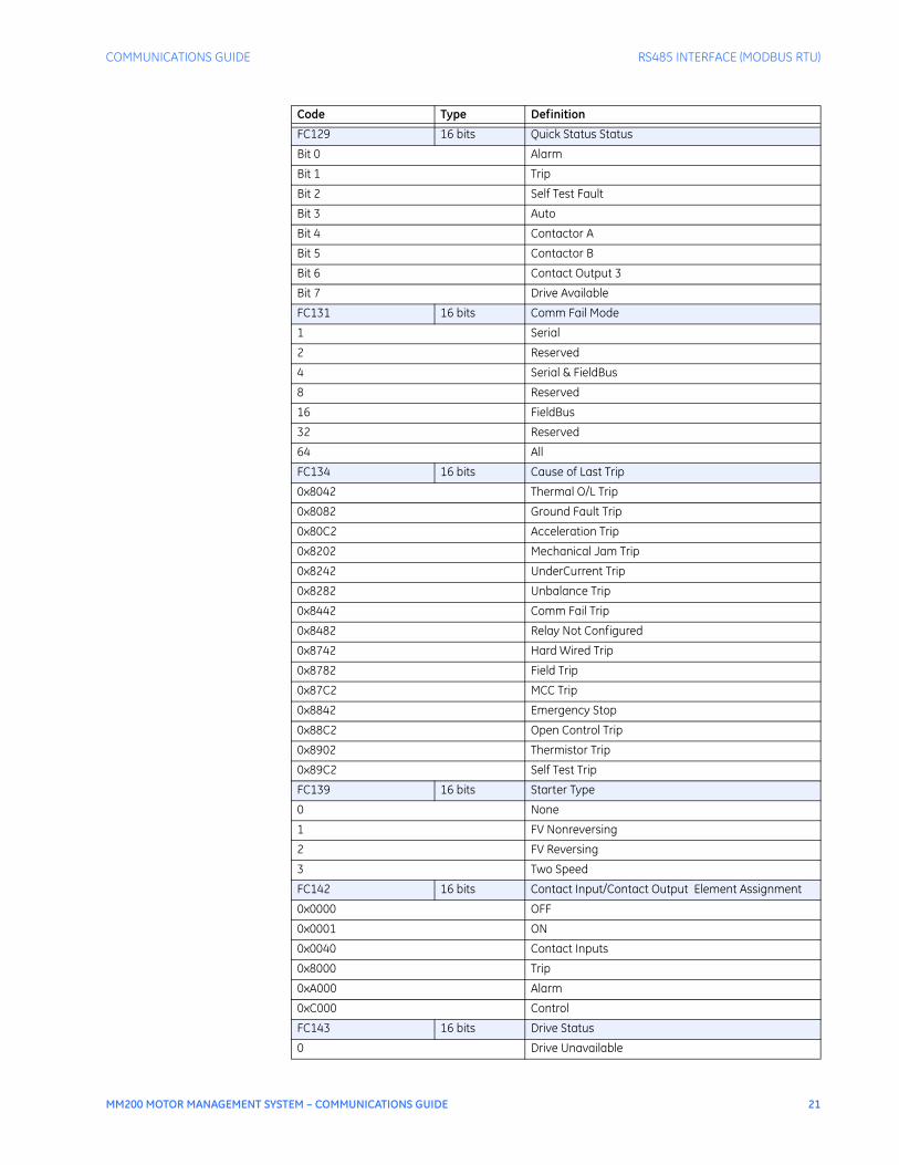
FC129 16 bits Quick Status Status
Bit 0 Alarm
Bit 1 Trip
Bit 2 Self Test Fault
Bit 3 Auto
Bit 4 Contactor A
Bit 5 Contactor B
Bit 6 Contact Output 3
Bit 7 Drive Available
FC131 16 bits Comm Fail Mode
1 Serial
2 Reserved
4 Serial & FieldBus
8 Reserved
16 FieldBus
32 Reserved
64 All
FC134 16 bits Cause of Last Trip
0x8042 Thermal O/L Trip
0x8082 Ground Fault Trip
0x80C2 Acceleration Trip
0x8202 Mechanical Jam Trip
0x8242 UnderCurrent Trip
0x8282 Unbalance Trip
0x8442 Comm Fail Trip
0x8482 Relay Not Configured
0x8742 Hard Wired Trip
0x8782 Field Trip
0x87C2 MCC Trip
0x8842 Emergency Stop
0x88C2 Open Control Trip
0x8902 Thermistor Trip
0x89C2 Self Test Trip
FC139 16 bits Starter Type
0 None
1 FV Nonreversing
2 FV Reversing
3 Two Speed
FC142 16 bits Contact Input/Contact Output Element Assignment
0x0000 OFF
0x0001 ON
0x0040 Contact Inputs
0x8000 Trip
0xA000 Alarm
0xC000 Control
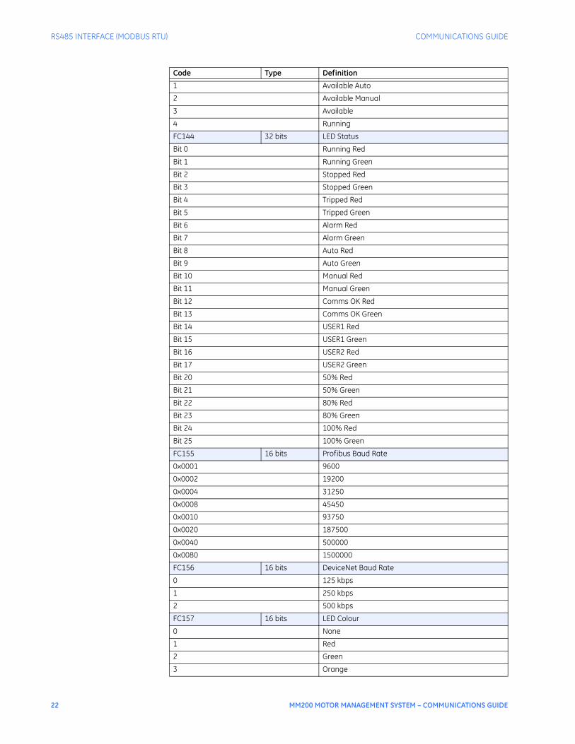
FC143 16 bits Drive Status
0 Drive Unavailable
Code Type Definition
22 MM200 MOTOR MANAGEMENT SYSTEM – COMMUNICATIONS GUIDE
RS485 INTERFACE (MODBUS RTU) COMMUNICATIONS GUIDE
1 Available Auto
2 Available Manual
3 Available
4 Running
FC144 32 bits LED Status
Bit 0 Running Red
Bit 1 Running Green
Bit 2 Stopped Red
Bit 3 Stopped Green
Bit 4 Tripped Red
Bit 5 Tripped Green
Bit 6 Alarm Red
Bit 7 Alarm Green
Bit 8 Auto Red
Bit 9 Auto Green
Bit 10 Manual Red
Bit 11 Manual Green
Bit 12 Comms OK Red
Bit 13 Comms OK Green
Bit 14 USER1 Red
Bit 15 USER1 Green
Bit 16 USER2 Red
Bit 17 USER2 Green
Bit 20 50% Red
Bit 21 50% Green
Bit 22 80% Red
Bit 23 80% Green
Bit 24 100% Red
Bit 25 100% Green
FC155 16 bits Profibus Baud Rate
0x0001 9600
0x0002 19200
0x0004 31250
0x0008 45450
0x0010 93750
0x0020 187500
0x0040 500000
0x0080 1500000
FC156 16 bits DeviceNet Baud Rate
0 125 kbps
1 250 kbps
2 500 kbps
FC157 16 bits LED Colour
0 None
1 Red
2 Green
3 Orange
Code Type Definition

COMMUNICATIONS GUIDE RS485 INTERFACE (MODBUS RTU)
MM200 MOTOR MANAGEMENT SYSTEM – COMMUNICATIONS GUIDE 23
FC160 16 bits Auto/Manual Mode
0 Auto
1 Manual
FC167 32 bits Contact Input/Output Status
Bit 0 Input/Output 1
Bit 1 Input/Output 2
Bit 2 Input/Output 3
Bit 3 Input/Output 4
Bit 4 Input/Output 5
Bit 5 Input/Output 6
Bit 6 Input/Output 7
FC172 16 bits Auto/Manual Control Stop Mode
0 Always Enabled
1 Follow Ctrl Mode
FC173 16 bits Wire Selection
0 2W
1 3W
FC174 16 bits Source Stop Action
0 Stop
1 Trip
FC175 16 bits Test Auto/Manual Mode
0 ON
1 OFF
2 Unaffected
FC178 16 bits Motor Status
Bit 0 Lockout
Bit 1 Non-Lockout Trip
Bit 4 Running
Bit 5 Precontactor
Bit 6 Starting
Bit 8 Inhibit
Bit 9 Stopped
Bit 10 Self Test Fault
Bit 11 Alarm
Bit 12 Forward
Bit 13 Reverse
Bit 14 Low Speed
Bit 15 High Speed
FC179 32 bits Alarm Status 1
Bit 0 Any Alarm
Bit 1 Thermal Level Alarm
Bit 2 Ground Fault Alarm
Bit 3 Acceleration Alarm
Bit 9 UnderCurrent Alarm
Bit 10 Unbalance Alarm
FC180 32 bits Alarm Status 2
Bit 0 Aux U/V Alarm
Code Type Definition

24 MM200 MOTOR MANAGEMENT SYSTEM – COMMUNICATIONS GUIDE
RS485 INTERFACE (MODBUS RTU) COMMUNICATIONS GUIDE
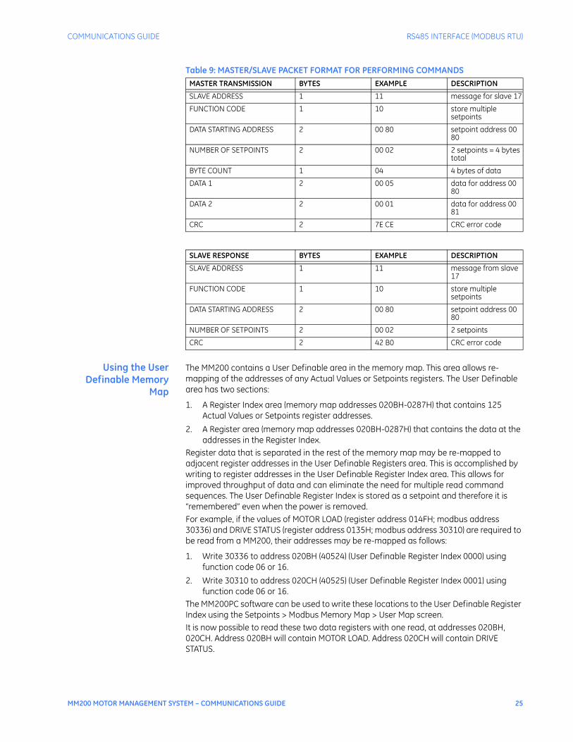
Performing Commands Using Function Code 10HCommands can be performed using function code 16 as well as function code 5. When using FUNCTION CODE 16, the Command Function register must be written with a value of 5. The Command Operation register must be written with a valid command operation number. The Command Data registers must be written with valid data; this is dependent upon the command operation. For example, consider a request for slave 17 to perform command operation 1 (RESET): The master/slave packets have the following format:
Bit 1 External Stop Alarm
Bit 3 Open Ctrl Cct Alarm
Bit 4 Thermistor Alarm
Bit 6 External Start A Alarm
Bit 7 External Start B Alarm
Bit 8 Welded Contactor
Bit 12 Load Increase Alarm
Bit 13 Drive Greasing Alarm
Bit 14 Contactor Inspect Alarm
Bit 15 Max Stopped Alarm
Bit 18 Comm Fail Alarm
FC183 32 bits Trip Status 1
Bit 0 Any Trip
Bit 1 Thermal O/L Trip
Bit 2 Ground Fault Trip
Bit 3 Acceleration Trip
Bit 8 Mechanical Jam Trip
Bit 9 UnderCurrent Trip
Bit 10 Unbalance Trip
Bit 29 Hard Wired Trip
Bit 30 Field Trip
Bit 31 MCC Trip
FC184 32 bits Trip Status 2
Bit 1 Emergency Stop
Bit 3 OpenControl Circuit
Bit 4 Thermistor Trip
FC191 32 bits Ctrl Element Status 1
Bit 0 Any Stop
Bit 1 Thermal Inhibit
Bit 2 AutoMode
Bit 3 Manual Mode
Bit 4 AutoManualMode
Bit 8 Forward Limit
Bit 9 Reverse Limit
Bit 15 Comms Ctrl Active
Bit 16 Hard Wired Ctrl Active
Bit 17 Field Ctrl Active
Bit 18 MCC Ctrl Active
Code Type Definition
COMMUNICATIONS GUIDE RS485 INTERFACE (MODBUS RTU)
MM200 MOTOR MANAGEMENT SYSTEM – COMMUNICATIONS GUIDE 25
Table 9: MASTER/SLAVE PACKET FORMAT FOR PERFORMING COMMANDS
Using the UserDefinable Memory
Map
The MM200 contains a User Definable area in the memory map. This area allows re-mapping of the addresses of any Actual Values or Setpoints registers. The User Definable area has two sections:
1. A Register Index area (memory map addresses 020BH-0287H) that contains 125 Actual Values or Setpoints register addresses.
2. A Register area (memory map addresses 020BH-0287H) that contains the data at the addresses in the Register Index.
Register data that is separated in the rest of the memory map may be re-mapped to adjacent register addresses in the User Definable Registers area. This is accomplished by writing to register addresses in the User Definable Register Index area. This allows for improved throughput of data and can eliminate the need for multiple read command sequences. The User Definable Register Index is stored as a setpoint and therefore it is “remembered” even when the power is removed.For example, if the values of MOTOR LOAD (register address 014FH; modbus address 30336) and DRIVE STATUS (register address 0135H; modbus address 30310) are required to be read from a MM200, their addresses may be re-mapped as follows:
1. Write 30336 to address 020BH (40524) (User Definable Register Index 0000) using function code 06 or 16.
2. Write 30310 to address 020CH (40525) (User Definable Register Index 0001) using function code 06 or 16.
The MM200PC software can be used to write these locations to the User Definable Register Index using the Setpoints > Modbus Memory Map > User Map screen.It is now possible to read these two data registers with one read, at addresses 020BH, 020CH. Address 020BH will contain MOTOR LOAD. Address 020CH will contain DRIVE STATUS.
MASTER TRANSMISSION BYTES EXAMPLE DESCRIPTION
SLAVE ADDRESS 1 11 message for slave 17
FUNCTION CODE 1 10 store multiple setpoints
DATA STARTING ADDRESS 2 00 80 setpoint address 00 80
NUMBER OF SETPOINTS 2 00 02 2 setpoints = 4 bytes total
BYTE COUNT 1 04 4 bytes of data
DATA 1 2 00 05 data for address 00 80
DATA 2 2 00 01 data for address 00 81
CRC 2 7E CE CRC error code
SLAVE RESPONSE BYTES EXAMPLE DESCRIPTION
SLAVE ADDRESS 1 11 message from slave 17
FUNCTION CODE 1 10 store multiple setpoints
DATA STARTING ADDRESS 2 00 80 setpoint address 00 80
NUMBER OF SETPOINTS 2 00 02 2 setpoints
CRC 2 42 B0 CRC error code
26 MM200 MOTOR MANAGEMENT SYSTEM – COMMUNICATIONS GUIDE
FIELDBUS INTERFACE COMMUNICATIONS GUIDE
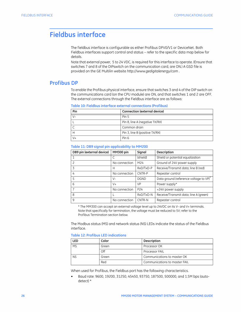
Fieldbus interface
The fieldbus interface is configurable as either Profibus DPV0/V1 or DeviceNet. Both Fieldbus interfaces support control and status – refer to the specific data map below for details. Note that external power, 5 to 24 VDC, is required for this interface to operate. (Ensure that switches 7 and 8 of the DIPswitch on the communication card, are ON.) A GSD file is provided on the GE Multilin website http://www.gedigitalenergy/com .
Profibus DPTo enable the Profibus physical interface, ensure that switches 3 and 4 of the DIP switch on the communications card (on the CPU module) are ON, and that switches 1 and 2 are OFF. The external connections through the Fieldbus interface are as follows:
Table 10: Fieldbus interface external connections (Profibus)
Table 11: DB9 signal pin applicability to MM200
The Modbus status (MS) and network status (NS) LEDs indicate the status of the Fieldbus interface.
Table 12: Profibus LED indications
When used for Profibus, the Fieldbus port has the following characteristics.• Baud rate: 9600, 19200, 31250, 45450, 93750, 187500, 500000, and 1.5M bps (auto-
detect) *
Pin Connection (external device)
V– Pin 5
L Pin 8, line A (negative TX/RX)
C Common drain
H Pin 3, line B (positive TX/RX)
V+ Pin 6
DB9 pin (external device) MM300 pin Signal Description
1 C (shield) Shield or potential equalization
2 No connection M24 Ground of 24V power supply
3 H RxD/TxD-P Receive/Transmit data; line B (red)
4 No connection CNTR-P Repeater control
5 V- DGND Data ground (reference voltage to VP)*
* The MM300 can accept an external voltage level up to 24VDC on its V- and V+ terminals. Note that specifically for termination, the voltage must be reduced to 5V; refer to the Profibus Termination section below.
6 V+ VP Power supply*
7 No connection P24 +24V power supply
8 L RxD/TxD-N Receive/Transmit data; line A (green)
9 No connection CNTR-N Repeater control
LED Color Description
MS Green Processor OK
Off Processor FAIL
NS Green Communications to master OK
Red Communications to master FAIL

COMMUNICATIONS GUIDE FIELDBUS INTERFACE
MM200 MOTOR MANAGEMENT SYSTEM – COMMUNICATIONS GUIDE 27
• Address: 1 to 126• Vendor ID: 4D20 (hex)• Data table size: inputs = 174 bytes, outputs = 2 bytes• To be actioned, output bit must be 1 for a minimum time of 100 ms.* Profibus communications will operate only in 1.5Mbps or auto-detect with the present implementation. Auto-detect includes baud rates 19.2 kbps, 187.5 kbps, 500 kbps, and 1.5 Mbps.The Profibus DP Master must read the GSE (Device Master Data) file of the MM300 for the purposes of configuration and parameterization. The GSE file for the MM300 is named GEMU4D20.gse.
Profibus power supplyconfiguration
The Profibus port has two modes of powering the electronics: internal or external. In internal mode, a local 5 V is used, so no external voltage is required (pin 1 and pin 5 of the connector). In external mode, the user must supply an external bus voltage on pin1 and pin 5 of the connector. Profibus is shipped from the factory configured for internal mode. Use the figures below to configure the the comms board power supply.
Figure 1: Comms board power supply configuration
NOTE
NOTE: Other switch combinations are NOT ALLOWED.
Protocol Options
SW1 SW2 SW3 SW4
DeviceNet ON ON OFF OFF
Profibus OFF OFF ON ON
Supply Options
SW5 SW6 SW7 SW8
Internal ON ON OFF OFF
External OFF OFF ON ON
INTERNALSUPPLY
EXTERNALSUPPLY
ON
ON
888845A1.CDR
1 2 3 4 5 6 7 8
1 2 3 4 5 6 7 8
= switch position
28 MM200 MOTOR MANAGEMENT SYSTEM – COMMUNICATIONS GUIDE
FIELDBUS INTERFACE COMMUNICATIONS GUIDE
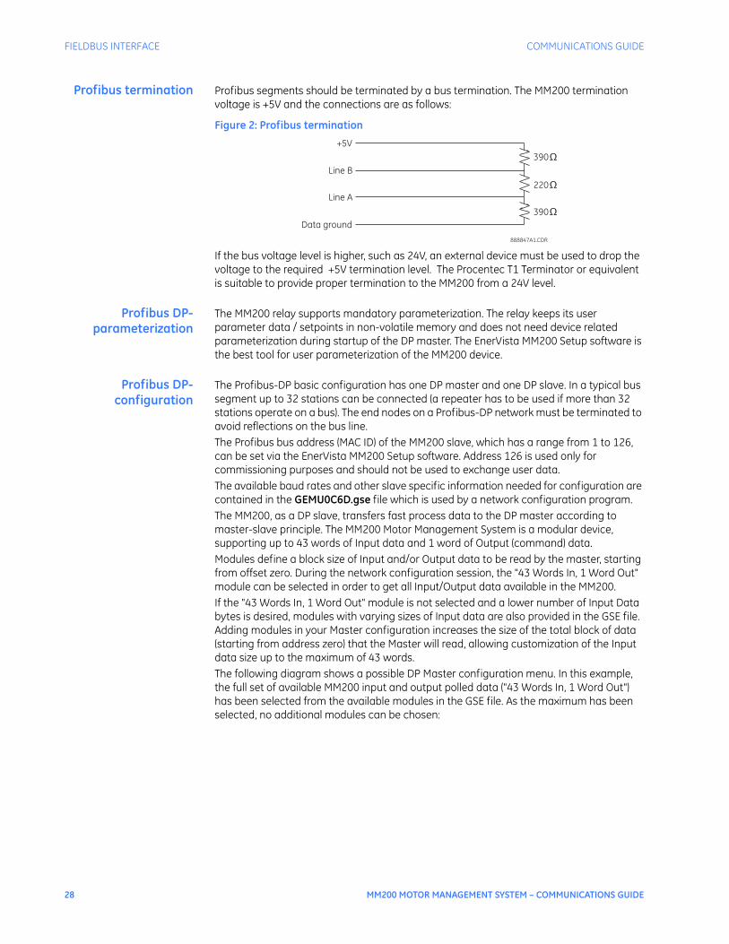
Profibus termination Profibus segments should be terminated by a bus termination. The MM200 termination voltage is +5V and the connections are as follows:
Figure 2: Profibus termination
If the bus voltage level is higher, such as 24V, an external device must be used to drop the voltage to the required +5V termination level. The Procentec T1 Terminator or equivalent is suitable to provide proper termination to the MM200 from a 24V level.
Profibus DP-parameterization
The MM200 relay supports mandatory parameterization. The relay keeps its user parameter data / setpoints in non-volatile memory and does not need device related parameterization during startup of the DP master. The EnerVista MM200 Setup software is the best tool for user parameterization of the MM200 device.
Profibus DP-configuration
The Profibus-DP basic configuration has one DP master and one DP slave. In a typical bus segment up to 32 stations can be connected (a repeater has to be used if more than 32 stations operate on a bus). The end nodes on a Profibus-DP network must be terminated to avoid reflections on the bus line. The Profibus bus address (MAC ID) of the MM200 slave, which has a range from 1 to 126, can be set via the EnerVista MM200 Setup software. Address 126 is used only for commissioning purposes and should not be used to exchange user data.The available baud rates and other slave specific information needed for configuration are contained in the GEMU0C6D.gse file which is used by a network configuration program.The MM200, as a DP slave, transfers fast process data to the DP master according to master-slave principle. The MM200 Motor Management System is a modular device, supporting up to 43 words of Input data and 1 word of Output (command) data. Modules define a block size of Input and/or Output data to be read by the master, starting from offset zero. During the network configuration session, the "43 Words In, 1 Word Out" module can be selected in order to get all Input/Output data available in the MM200.If the "43 Words In, 1 Word Out" module is not selected and a lower number of Input Data bytes is desired, modules with varying sizes of Input data are also provided in the GSE file. Adding modules in your Master configuration increases the size of the total block of data (starting from address zero) that the Master will read, allowing customization of the Input data size up to the maximum of 43 words.The following diagram shows a possible DP Master configuration menu. In this example, the full set of available MM200 input and output polled data ("43 Words In, 1 Word Out") has been selected from the available modules in the GSE file. As the maximum has been selected, no additional modules can be chosen:
888847A1.CDR
+5V
Line B
Line A
Data ground
390
220
390
Ω
Ω
Ω

COMMUNICATIONS GUIDE FIELDBUS INTERFACE
MM200 MOTOR MANAGEMENT SYSTEM – COMMUNICATIONS GUIDE 29
Figure 3: Profibus configuration menu
The diagram below shows the input and output data read from the MM200 with the configuration above
Figure 4: Profibus I/O data - 43 words in, 1 word out
The following DP Master configuration menu shows how a smaller set of I/O poll data can be chosen from the available modules in the GSE file. In this example, a total of 3 words of input and 1 word of output polled data has been selected:
30 MM200 MOTOR MANAGEMENT SYSTEM – COMMUNICATIONS GUIDE
FIELDBUS INTERFACE COMMUNICATIONS GUIDE
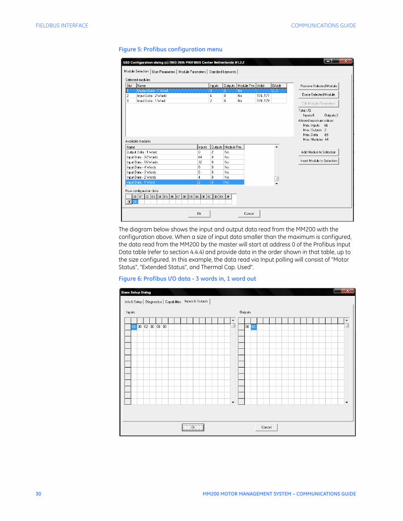
Figure 5: Profibus configuration menu
The diagram below shows the input and output data read from the MM200 with the configuration above. When a size of input data smaller than the maximum is configured, the data read from the MM200 by the master will start at address 0 of the Profibus Input Data table (refer to section 4.4.4) and provide data in the order shown in that table, up to the size configured. In this example, the data read via Input polling will consist of "Motor Status", "Extended Status", and Thermal Cap. Used".
Figure 6: Profibus I/O data - 3 words in, 1 word out
COMMUNICATIONS GUIDE FIELDBUS INTERFACE
MM200 MOTOR MANAGEMENT SYSTEM – COMMUNICATIONS GUIDE 31
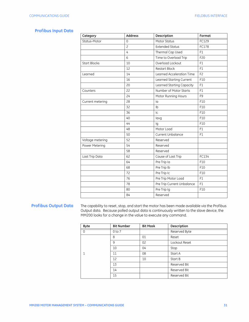
Profibus Input Data
Profibus Output Data The capability to reset, stop, and start the motor has been made available via the Profibus Output data. Because polled output data is continuously written to the slave device, the MM200 looks for a change in the value to execute any command.
Category Address Description Format
Status-Motor 0 Motor Status FC129
2 Extended Status FC178
4 Thermal Cap Used F1
6 Time to Overload Trip F20
Start Blocks 10 Overload Lockout F1
12 Restart Block F1
Learned 14 Learned Acceleration Time F2
16 Learned Starting Current F10
20 Learned Starting Capacity F1
Counters 22 Number of Motor Starts F1
24 Motor Running Hours F9
Current metering 28 Ia F10
32 Ib F10
36 Ic F10
40 Iavg F10
44 Ig F10
48 Motor Load F1
50 Current Unbalance F1
Voltage metering 52 Reserved
Power Metering 54 Reserved
58 Reserved
Last Trip Data 62 Cause of Last Trip FC134
64 Pre Trip Ia F10
68 Pre Trip Ib F10
72 Pre Trip Ic F10
76 Pre Trip Motor Load F1
78 Pre Trip Current Unbalance F1
80 Pre Trip Ig F10
84 Reserved
Byte Bit Number Bit Mask Description
0 0 to 7 Reserved Byte
8 01 Reset
9 02 Lockout Reset
10 04 Stop
1 11 08 Start A
12 10 Start B
13 Reserved Bit
14 Reserved Bit
15 Reserved Bit
32 MM200 MOTOR MANAGEMENT SYSTEM – COMMUNICATIONS GUIDE
FIELDBUS INTERFACE COMMUNICATIONS GUIDE
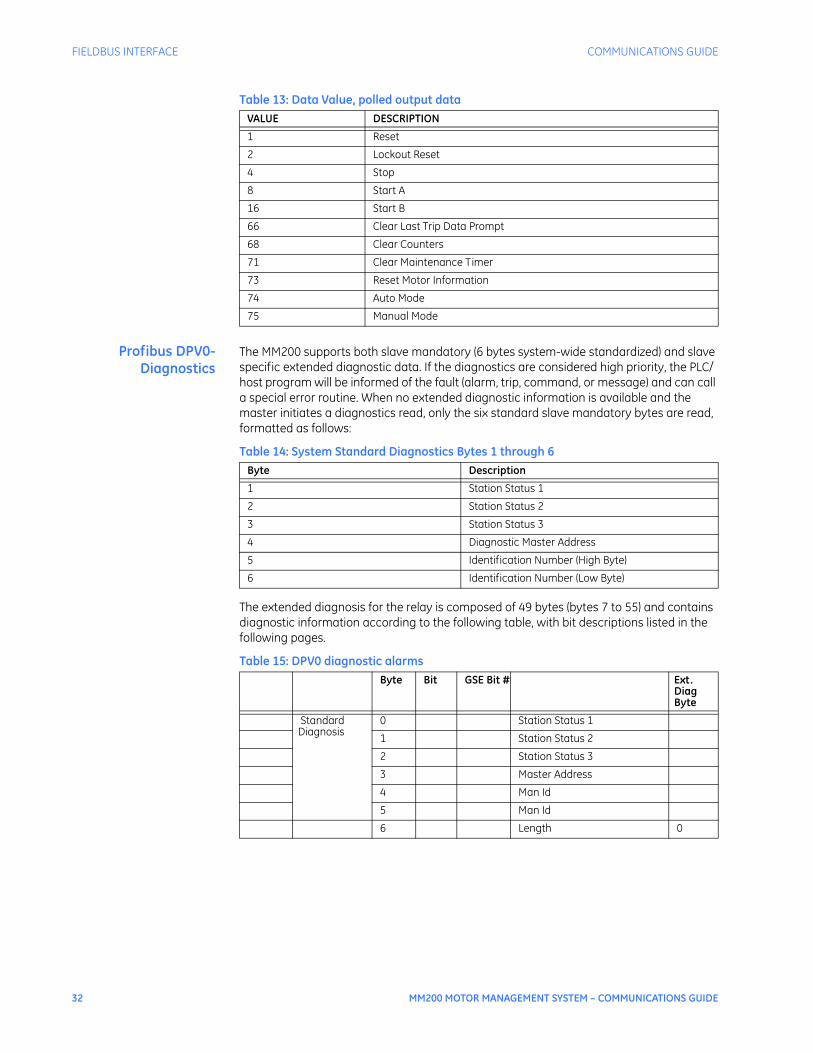
Table 13: Data Value, polled output data
Profibus DPV0-Diagnostics
The MM200 supports both slave mandatory (6 bytes system-wide standardized) and slave specific extended diagnostic data. If the diagnostics are considered high priority, the PLC/host program will be informed of the fault (alarm, trip, command, or message) and can call a special error routine. When no extended diagnostic information is available and the master initiates a diagnostics read, only the six standard slave mandatory bytes are read, formatted as follows:
Table 14: System Standard Diagnostics Bytes 1 through 6
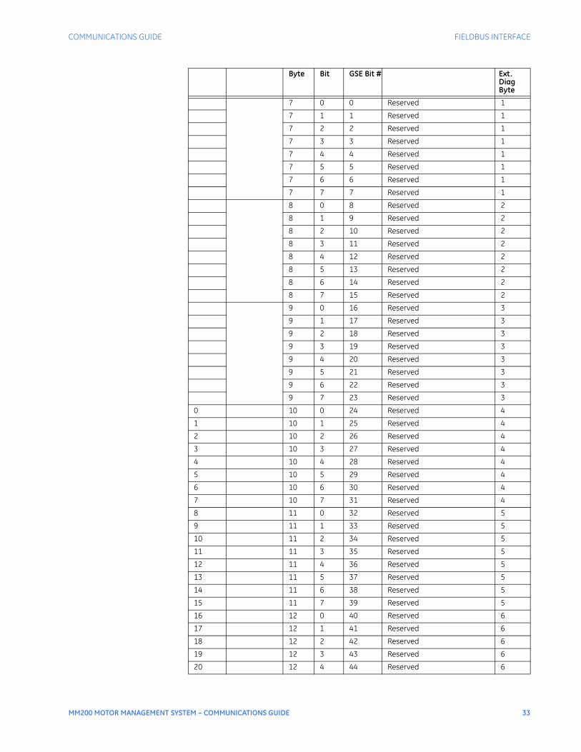
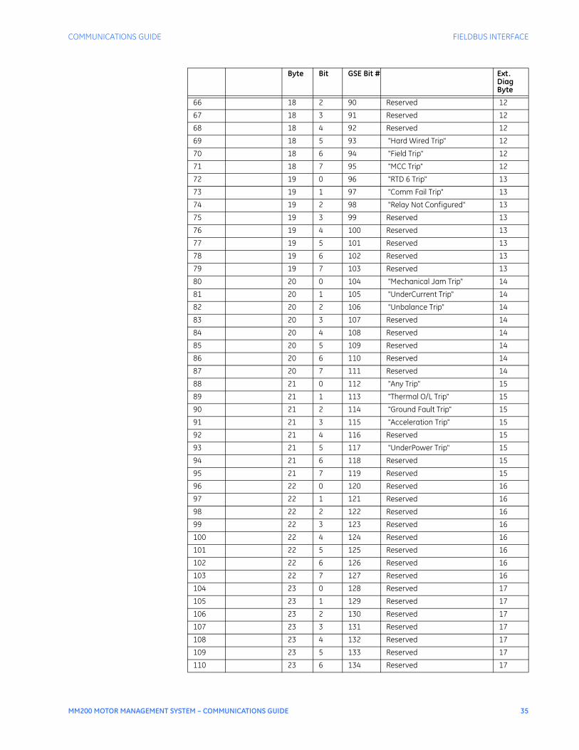
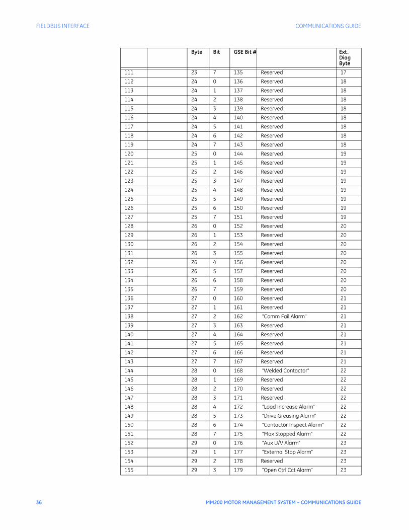
The extended diagnosis for the relay is composed of 49 bytes (bytes 7 to 55) and contains diagnostic information according to the following table, with bit descriptions listed in the following pages.
Table 15: DPV0 diagnostic alarms
VALUE DESCRIPTION
1 Reset
2 Lockout Reset
4 Stop
8 Start A
16 Start B
66 Clear Last Trip Data Prompt
68 Clear Counters
71 Clear Maintenance Timer
73 Reset Motor Information
74 Auto Mode
75 Manual Mode
Byte Description
1 Station Status 1
2 Station Status 2
3 Station Status 3
4 Diagnostic Master Address
5 Identification Number (High Byte)
6 Identification Number (Low Byte)
Byte Bit GSE Bit # Ext. Diag Byte
Standard Diagnosis
0 Station Status 1
1 Station Status 2
2 Station Status 3
3 Master Address
4 Man Id
5 Man Id
6 Length 0
COMMUNICATIONS GUIDE FIELDBUS INTERFACE
MM200 MOTOR MANAGEMENT SYSTEM – COMMUNICATIONS GUIDE 33
7 0 0 Reserved 1
7 1 1 Reserved 1
7 2 2 Reserved 1
7 3 3 Reserved 1
7 4 4 Reserved 1
7 5 5 Reserved 1
7 6 6 Reserved 1
7 7 7 Reserved 1
8 0 8 Reserved 2
8 1 9 Reserved 2
8 2 10 Reserved 2
8 3 11 Reserved 2
8 4 12 Reserved 2
8 5 13 Reserved 2
8 6 14 Reserved 2
8 7 15 Reserved 2
9 0 16 Reserved 3
9 1 17 Reserved 3
9 2 18 Reserved 3
9 3 19 Reserved 3
9 4 20 Reserved 3
9 5 21 Reserved 3
9 6 22 Reserved 3
9 7 23 Reserved 3
0 10 0 24 Reserved 4
1 10 1 25 Reserved 4
2 10 2 26 Reserved 4
3 10 3 27 Reserved 4
4 10 4 28 Reserved 4
5 10 5 29 Reserved 4
6 10 6 30 Reserved 4
7 10 7 31 Reserved 4
8 11 0 32 Reserved 5
9 11 1 33 Reserved 5
10 11 2 34 Reserved 5
11 11 3 35 Reserved 5
12 11 4 36 Reserved 5
13 11 5 37 Reserved 5
14 11 6 38 Reserved 5
15 11 7 39 Reserved 5
16 12 0 40 Reserved 6
17 12 1 41 Reserved 6
18 12 2 42 Reserved 6
19 12 3 43 Reserved 6
20 12 4 44 Reserved 6
Byte Bit GSE Bit # Ext. Diag Byte

34 MM200 MOTOR MANAGEMENT SYSTEM – COMMUNICATIONS GUIDE
FIELDBUS INTERFACE COMMUNICATIONS GUIDE
21 12 5 45 Reserved 6
22 12 6 46 Reserved 6
23 12 7 47 Reserved 6
24 13 0 48 Reserved 7
25 13 1 49 Reserved 7
26 13 2 50 Reserved 7
27 13 3 51 Reserved 7
28 13 4 52 Reserved 7
29 13 5 53 Reserved 7
30 13 6 54 Reserved 7
31 13 7 55 Reserved 7
32 14 0 56 Reserved 8
33 14 1 57 Reserved 8
34 14 2 58 Reserved 8
35 14 3 59 Reserved 8
36 14 4 60 Reserved 8
37 14 5 61 Reserved 8
38 14 6 62 Reserved 8
39 14 7 63 Reserved 8
40 15 0 64 Reserved 9
41 15 1 65 Reserved 9
42 15 2 66 Reserved 9
43 15 3 67 Reserved 9
44 15 4 68 Reserved 9
45 15 5 69 Reserved 9
46 15 6 70 Reserved 9
47 15 7 71 Reserved 9
48 16 0 72 Reserved 10
49 16 1 73 Reserved 10
50 16 2 74 Reserved 10
51 16 3 75 Reserved 10
52 16 4 76 Reserved 10
53 16 5 77 Reserved 10
54 16 6 78 Reserved 10
55 16 7 79 Reserved 10
56 17 0 80 "Aux U/V Trip" 11
57 17 1 81 "Emergency Stop" 11
58 17 2 82 Reserved 11
59 17 3 83 "OpenControl Circuit" 11
60 17 4 84 "Thermistor Trip" 11
61 17 5 85 Reserved 11
62 17 6 86 Reserved 11
63 17 7 87 "Self Test Trip" 11
64 18 0 88 Reserved 12
65 18 1 89 Reserved 12
Byte Bit GSE Bit # Ext. Diag Byte
COMMUNICATIONS GUIDE FIELDBUS INTERFACE
MM200 MOTOR MANAGEMENT SYSTEM – COMMUNICATIONS GUIDE 35
66 18 2 90 Reserved 12
67 18 3 91 Reserved 12
68 18 4 92 Reserved 12
69 18 5 93 "Hard Wired Trip" 12
70 18 6 94 "Field Trip" 12
71 18 7 95 "MCC Trip" 12
72 19 0 96 "RTD 6 Trip" 13
73 19 1 97 "Comm Fail Trip" 13
74 19 2 98 "Relay Not Configured" 13
75 19 3 99 Reserved 13
76 19 4 100 Reserved 13
77 19 5 101 Reserved 13
78 19 6 102 Reserved 13
79 19 7 103 Reserved 13
80 20 0 104 "Mechanical Jam Trip" 14
81 20 1 105 "UnderCurrent Trip" 14
82 20 2 106 "Unbalance Trip" 14
83 20 3 107 Reserved 14
84 20 4 108 Reserved 14
85 20 5 109 Reserved 14
86 20 6 110 Reserved 14
87 20 7 111 Reserved 14
88 21 0 112 "Any Trip" 15
89 21 1 113 "Thermal O/L Trip" 15
90 21 2 114 "Ground Fault Trip" 15
91 21 3 115 "Acceleration Trip" 15
92 21 4 116 Reserved 15
93 21 5 117 "UnderPower Trip" 15
94 21 6 118 Reserved 15
95 21 7 119 Reserved 15
96 22 0 120 Reserved 16
97 22 1 121 Reserved 16
98 22 2 122 Reserved 16
99 22 3 123 Reserved 16
100 22 4 124 Reserved 16
101 22 5 125 Reserved 16
102 22 6 126 Reserved 16
103 22 7 127 Reserved 16
104 23 0 128 Reserved 17
105 23 1 129 Reserved 17
106 23 2 130 Reserved 17
107 23 3 131 Reserved 17
108 23 4 132 Reserved 17
109 23 5 133 Reserved 17
110 23 6 134 Reserved 17
Byte Bit GSE Bit # Ext. Diag Byte
36 MM200 MOTOR MANAGEMENT SYSTEM – COMMUNICATIONS GUIDE
FIELDBUS INTERFACE COMMUNICATIONS GUIDE
111 23 7 135 Reserved 17
112 24 0 136 Reserved 18
113 24 1 137 Reserved 18
114 24 2 138 Reserved 18
115 24 3 139 Reserved 18
116 24 4 140 Reserved 18
117 24 5 141 Reserved 18
118 24 6 142 Reserved 18
119 24 7 143 Reserved 18
120 25 0 144 Reserved 19
121 25 1 145 Reserved 19
122 25 2 146 Reserved 19
123 25 3 147 Reserved 19
124 25 4 148 Reserved 19
125 25 5 149 Reserved 19
126 25 6 150 Reserved 19
127 25 7 151 Reserved 19
128 26 0 152 Reserved 20
129 26 1 153 Reserved 20
130 26 2 154 Reserved 20
131 26 3 155 Reserved 20
132 26 4 156 Reserved 20
133 26 5 157 Reserved 20
134 26 6 158 Reserved 20
135 26 7 159 Reserved 20
136 27 0 160 Reserved 21
137 27 1 161 Reserved 21
138 27 2 162 "Comm Fail Alarm" 21
139 27 3 163 Reserved 21
140 27 4 164 Reserved 21
141 27 5 165 Reserved 21
142 27 6 166 Reserved 21
143 27 7 167 Reserved 21
144 28 0 168 "Welded Contactor" 22
145 28 1 169 Reserved 22
146 28 2 170 Reserved 22
147 28 3 171 Reserved 22
148 28 4 172 "Load Increase Alarm" 22
149 28 5 173 "Drive Greasing Alarm" 22
150 28 6 174 "Contactor Inspect Alarm" 22
151 28 7 175 "Max Stopped Alarm" 22
152 29 0 176 "Aux U/V Alarm" 23
153 29 1 177 "External Stop Alarm" 23
154 29 2 178 Reserved 23
155 29 3 179 "Open Ctrl Cct Alarm" 23
Byte Bit GSE Bit # Ext. Diag Byte

COMMUNICATIONS GUIDE FIELDBUS INTERFACE
MM200 MOTOR MANAGEMENT SYSTEM – COMMUNICATIONS GUIDE 37
156 29 4 180 "Thermistor Alarm" 23
157 29 5 181 Reserved 23
158 29 6 182 "External Start A Alarm" 23
159 29 7 183 "External Start B Alarm" 23
160 30 0 184 Reserved 24
161 30 1 185 Reserved 24
162 30 2 186 Reserved 24
163 30 3 187 Reserved 24
164 30 4 188 Reserved 24
165 30 5 189 Reserved 24
166 30 6 190 Reserved 24
167 30 7 191 Reserved 24
168 31 0 192 Reserved 25
169 31 1 193 Reserved 25
170 31 2 194 Reserved 25
171 31 3 195 Reserved 25
172 31 4 196 Reserved 25
173 31 5 197 Reserved 25
174 31 6 198 Reserved 25
175 31 7 199 Reserved 25
176 32 0 200 Reserved 26
177 32 1 201 "UnderCurrent Alarm" 26
178 32 2 202 "Unbalance Alarm" 26
179 32 3 203 Reserved 26
180 32 4 204 Reserved 26
181 32 5 205 Reserved 26
182 32 6 206 Reserved 26
183 32 7 207 Reserved 26
184 33 0 208 "Any Alarm" 27
185 33 1 209 "Thermal Level Alarm" 27
186 33 2 210 "Ground Fault Alarm" 27
187 33 3 211 "Acceleration Alarm" 27
188 33 4 212 Reserved 27
189 33 5 213 "UnderPower Alarm" 27
190 33 6 214 Reserved 27
191 33 7 215 Reserved 27
192 34 0 216 Reserved 28
193 34 1 217 Reserved 28
194 34 2 218 Reserved 28
195 34 3 219 Reserved 28
196 34 4 220 Reserved 28
197 34 5 221 Reserved 28
198 34 6 222 Reserved 28
199 34 7 223 Reserved 28
200 35 0 224 Reserved 29
Byte Bit GSE Bit # Ext. Diag Byte

38 MM200 MOTOR MANAGEMENT SYSTEM – COMMUNICATIONS GUIDE
FIELDBUS INTERFACE COMMUNICATIONS GUIDE
201 35 1 225 Reserved 29
202 35 2 226 Reserved 29
203 35 3 227 Reserved 29
204 35 4 228 Reserved 29
205 35 5 229 Reserved 29
206 35 6 230 Reserved 29
207 35 7 231 Reserved 29
208 36 0 232 Reserved 30
209 36 1 233 Reserved 30
210 36 2 234 Reserved 30
211 36 3 235 Reserved 30
212 36 4 236 Reserved 30
213 36 5 237 Reserved 30
214 36 6 238 Reserved 30
215 36 7 239 Reserved 30
216 37 0 240 Reserved 31
217 37 1 241 Reserved 31
218 37 2 242 Reserved 31
219 37 3 243 Reserved 31
220 37 4 244 Reserved 31
221 37 5 245 Reserved 31
222 37 6 246 Reserved 31
223 37 7 247 Reserved 31
224 38 0 248 Reserved 32
225 38 1 249 Reserved 32
226 38 2 250 Reserved 32
227 38 3 251 Reserved 32
228 38 4 252 Reserved 32
229 38 5 253 Reserved 32
230 38 6 254 Reserved 32
231 38 7 255 Reserved 32
232 39 0 256 Reserved 33
233 39 1 257 Reserved 33
234 39 2 258 Reserved 33
235 39 3 259 Reserved 33
236 39 4 260 Reserved 33
237 39 5 261 Reserved 33
238 39 6 262 Reserved 33
239 39 7 263 Reserved 33
240 40 0 264 Reserved 34
241 40 1 265 Reserved 34
242 40 2 266 Reserved 34
243 40 3 267 Reserved 34
244 40 4 268 Reserved 34
245 40 5 269 Reserved 34
Byte Bit GSE Bit # Ext. Diag Byte
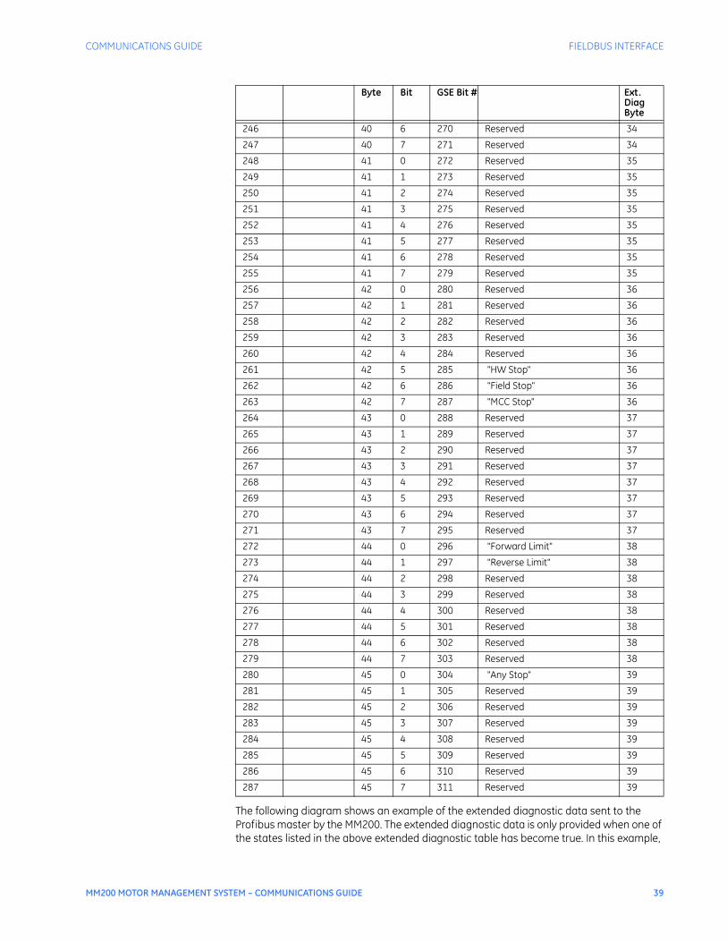
COMMUNICATIONS GUIDE FIELDBUS INTERFACE
MM200 MOTOR MANAGEMENT SYSTEM – COMMUNICATIONS GUIDE 39
The following diagram shows an example of the extended diagnostic data sent to the Profibus master by the MM200. The extended diagnostic data is only provided when one of the states listed in the above extended diagnostic table has become true. In this example,
246 40 6 270 Reserved 34
247 40 7 271 Reserved 34
248 41 0 272 Reserved 35
249 41 1 273 Reserved 35
250 41 2 274 Reserved 35
251 41 3 275 Reserved 35
252 41 4 276 Reserved 35
253 41 5 277 Reserved 35
254 41 6 278 Reserved 35
255 41 7 279 Reserved 35
256 42 0 280 Reserved 36
257 42 1 281 Reserved 36
258 42 2 282 Reserved 36
259 42 3 283 Reserved 36
260 42 4 284 Reserved 36
261 42 5 285 "HW Stop" 36
262 42 6 286 "Field Stop" 36
263 42 7 287 "MCC Stop" 36
264 43 0 288 Reserved 37
265 43 1 289 Reserved 37
266 43 2 290 Reserved 37
267 43 3 291 Reserved 37
268 43 4 292 Reserved 37
269 43 5 293 Reserved 37
270 43 6 294 Reserved 37
271 43 7 295 Reserved 37
272 44 0 296 "Forward Limit" 38
273 44 1 297 "Reverse Limit" 38
274 44 2 298 Reserved 38
275 44 3 299 Reserved 38
276 44 4 300 Reserved 38
277 44 5 301 Reserved 38
278 44 6 302 Reserved 38
279 44 7 303 Reserved 38
280 45 0 304 "Any Stop" 39
281 45 1 305 Reserved 39
282 45 2 306 Reserved 39
283 45 3 307 Reserved 39
284 45 4 308 Reserved 39
285 45 5 309 Reserved 39
286 45 6 310 Reserved 39
287 45 7 311 Reserved 39
Byte Bit GSE Bit # Ext. Diag Byte
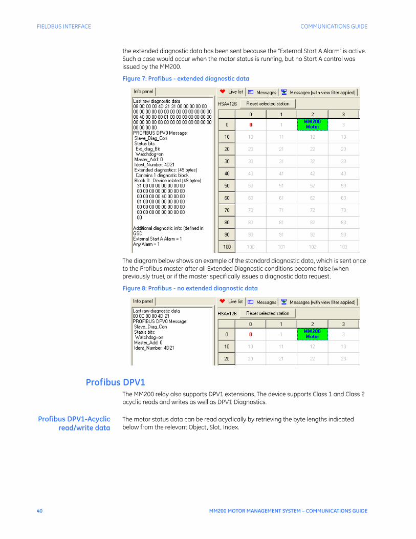
40 MM200 MOTOR MANAGEMENT SYSTEM – COMMUNICATIONS GUIDE
FIELDBUS INTERFACE COMMUNICATIONS GUIDE
the extended diagnostic data has been sent because the "External Start A Alarm" is active. Such a case would occur when the motor status is running, but no Start A control was issued by the MM200.
Figure 7: Profibus - extended diagnostic data
The diagram below shows an example of the standard diagnostic data, which is sent once to the Profibus master after all Extended Diagnostic conditions become false (when previously true), or if the master specifically issues a diagnostic data request.
Figure 8: Profibus - no extended diagnostic data
Profibus DPV1The MM200 relay also supports DPV1 extensions. The device supports Class 1 and Class 2 acyclic reads and writes as well as DPV1 Diagnostics.
Profibus DPV1-Acyclicread/write data
The motor status data can be read acyclically by retrieving the byte lengths indicated below from the relevant Object, Slot, Index.
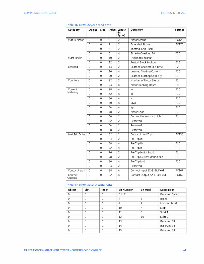
COMMUNICATIONS GUIDE FIELDBUS INTERFACE
MM200 MOTOR MANAGEMENT SYSTEM – COMMUNICATIONS GUIDE 41
Table 16: DPV1 Acyclic read data
Table 17: DPV1 acyclic write data
Category Object Slot Index Length (in Bytes)
Data Item Format
Status-Motor 0 0 0 2 Motor Status FC129
0 0 2 2 Extended Status FC178
0 0 4 2 Thermal Cap Used F1
0 0 6 4 Time to Overload Trip F20
Start Blocks 0 0 10 2 Overload Lockout F1
0 0 12 2 Restart Block Lockout F1B
Learned 0 0 14 2 Learned Acceleration Time F2
0 0 16 4 Learned Starting Current F10
0 0 20 2 Learned Starting Capacity F1
Counters 0 0 22 2 Number of Motor Starts F1
0 0 24 4 Motor Running Hours F9
Current Metering
0 0 28 4 Ia F10
0 0 32 4 Ib F10
0 0 36 4 Ic F10
0 0 40 4 Iavg F10
0 0 44 4 Igrd F10
0 0 48 2 Motor Load F1
0 0 50 2 Current Unbalance (I Unb) F1
0 0 52 2 Reserved
0 0 54 2 Reserved
0 0 58 2 Reserved
Last Trip Data 0 0 62 2 Cause of Last Trip FC134
0 0 64 2 Pre Trip Ia F10
0 0 68 4 Pre Trip Ib F10
0 0 72 4 Pre Trip Ic F10
0 0 76 2 Pre Trip Motor Load F1
0 0 78 2 Pre Trip Current Unbalance F1
0 0 80 4 Pre Trip Igrd F10
0 0 84 2 Reserved
Contact Inputs 0 0 88 4 Contact Input 32-1 (Bit Field) FC167
Contact Outputs
0 0 92 4 Contact Output 32-1 (Bit Field) FC167
Object Slot Index Bit Number Bit Mask Description
0 0 0 0 to 7 Reserved Byte
0 0 0 8 1 Reset
0 0 0 9 2 Lockout Reset
0 0 0 10 4 Stop
0 0 0 11 8 Start A
0 0 0 12 10 Start B
0 0 0 13 Reserved Bit
0 0 0 14 Reserved Bit
0 0 0 15 Reserved Bit

42 MM200 MOTOR MANAGEMENT SYSTEM – COMMUNICATIONS GUIDE
FIELDBUS INTERFACE COMMUNICATIONS GUIDE
Profibus DPV1-Diagnostics
MM200 DPV1 diagnosis data is structured as shown below: The extended diagnosis consists of Process Alarms and Diagnostic Alarms.Trip, Alarm, and Control status are categorized as Process Alarms, as these provide information pertaining to the Motor health that MM200 is controlling and monitoring.Messages are categorized as Diagnostic Alarms as these provide detailed MM200 diagnostic information.The detailed message layout explaining what information each bit provides is as follows:
Table 18: DPV1 diagnostic alarms Byte Bit GSE Bit # Ext.
Diag Byte
Standard Diagnosis
0 Station Status 1
1 Station Status 2
2 Station Status 3
3 Master Address
4 Man Id
5 Man Id
6 Length 0
Alarm Type 7 0 0 Alarm Type - Process Alarm 1
7 1 1 1
7 2 2 1
7 3 3 1
7 4 4 1
7 5 5 1
7 6 6 1
7 7 7 1
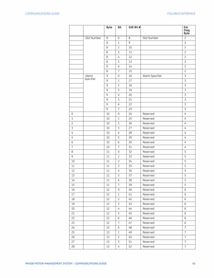
COMMUNICATIONS GUIDE FIELDBUS INTERFACE
MM200 MOTOR MANAGEMENT SYSTEM – COMMUNICATIONS GUIDE 43
Slot Number 8 0 8 Slot Number 2
8 1 9 2
8 2 10 2
8 3 11 2
8 4 12 2
8 5 13 2
8 6 14 2
8 7 15 2
Alarm Specifier
9 0 16 Alarm Specifier 3
9 1 17 3
9 2 18 3
9 3 19 3
9 4 20 3
9 5 21 3
9 6 22 3
9 7 23 3
0 10 0 24 Reserved 4
1 10 1 25 Reserved 4
2 10 2 26 Reserved 4
3 10 3 27 Reserved 4
4 10 4 28 Reserved 4
5 10 5 29 Reserved 4
6 10 6 30 Reserved 4
7 10 7 31 Reserved 4
8 11 0 32 Reserved 5
9 11 1 33 Reserved 5
10 11 2 34 Reserved 5
11 11 3 35 Reserved 5
12 11 4 36 Reserved 5
13 11 5 37 Reserved 5
14 11 6 38 Reserved 5
15 11 7 39 Reserved 5
16 12 0 40 Reserved 6
17 12 1 41 Reserved 6
18 12 2 42 Reserved 6
19 12 3 43 Reserved 6
20 12 4 44 Reserved 6
21 12 5 45 Reserved 6
22 12 6 46 Reserved 6
23 12 7 47 Reserved 6
24 13 0 48 Reserved 7
25 13 1 49 Reserved 7
26 13 2 50 Reserved 7
27 13 3 51 Reserved 7
28 13 4 52 Reserved 7
Byte Bit GSE Bit # Ext. Diag Byte
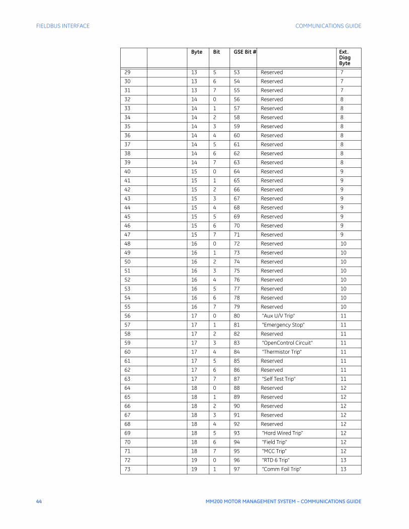
44 MM200 MOTOR MANAGEMENT SYSTEM – COMMUNICATIONS GUIDE
FIELDBUS INTERFACE COMMUNICATIONS GUIDE
29 13 5 53 Reserved 7
30 13 6 54 Reserved 7
31 13 7 55 Reserved 7
32 14 0 56 Reserved 8
33 14 1 57 Reserved 8
34 14 2 58 Reserved 8
35 14 3 59 Reserved 8
36 14 4 60 Reserved 8
37 14 5 61 Reserved 8
38 14 6 62 Reserved 8
39 14 7 63 Reserved 8
40 15 0 64 Reserved 9
41 15 1 65 Reserved 9
42 15 2 66 Reserved 9
43 15 3 67 Reserved 9
44 15 4 68 Reserved 9
45 15 5 69 Reserved 9
46 15 6 70 Reserved 9
47 15 7 71 Reserved 9
48 16 0 72 Reserved 10
49 16 1 73 Reserved 10
50 16 2 74 Reserved 10
51 16 3 75 Reserved 10
52 16 4 76 Reserved 10
53 16 5 77 Reserved 10
54 16 6 78 Reserved 10
55 16 7 79 Reserved 10
56 17 0 80 "Aux U/V Trip" 11
57 17 1 81 "Emergency Stop" 11
58 17 2 82 Reserved 11
59 17 3 83 "OpenControl Circuit" 11
60 17 4 84 "Thermistor Trip" 11
61 17 5 85 Reserved 11
62 17 6 86 Reserved 11
63 17 7 87 "Self Test Trip" 11
64 18 0 88 Reserved 12
65 18 1 89 Reserved 12
66 18 2 90 Reserved 12
67 18 3 91 Reserved 12
68 18 4 92 Reserved 12
69 18 5 93 "Hard Wired Trip" 12
70 18 6 94 "Field Trip" 12
71 18 7 95 "MCC Trip" 12
72 19 0 96 "RTD 6 Trip" 13
73 19 1 97 "Comm Fail Trip" 13
Byte Bit GSE Bit # Ext. Diag Byte

COMMUNICATIONS GUIDE FIELDBUS INTERFACE
MM200 MOTOR MANAGEMENT SYSTEM – COMMUNICATIONS GUIDE 45
74 19 2 98 "Relay Not Configured" 13
75 19 3 99 Reserved 13
76 19 4 100 Reserved 13
77 19 5 101 Reserved 13
78 19 6 102 Reserved 13
79 19 7 103 Reserved 13
80 20 0 104 "Mechanical Jam Trip" 14
81 20 1 105 "UnderCurrent Trip" 14
82 20 2 106 "Unbalance Trip" 14
83 20 3 107 Reserved 14
84 20 4 108 Reserved 14
85 20 5 109 Reserved 14
86 20 6 110 Reserved 14
87 20 7 111 Reserved 14
88 21 0 112 "Any Trip" 15
89 21 1 113 "Thermal O/L Trip" 15
90 21 2 114 "Ground Fault Trip" 15
91 21 3 115 "Acceleration Trip" 15
92 21 4 116 Reserved 15
93 21 5 117 "UnderPower Trip" 15
94 21 6 118 Reserved 15
95 21 7 119 Reserved 15
96 22 0 120 Reserved 16
97 22 1 121 Reserved 16
98 22 2 122 Reserved 16
99 22 3 123 Reserved 16
100 22 4 124 Reserved 16
101 22 5 125 Reserved 16
102 22 6 126 Reserved 16
103 22 7 127 Reserved 16
104 23 0 128 Reserved 17
105 23 1 129 Reserved 17
106 23 2 130 Reserved 17
107 23 3 131 Reserved 17
108 23 4 132 Reserved 17
109 23 5 133 Reserved 17
110 23 6 134 Reserved 17
111 23 7 135 Reserved 17
112 24 0 136 Reserved 18
113 24 1 137 Reserved 18
114 24 2 138 Reserved 18
115 24 3 139 Reserved 18
116 24 4 140 Reserved 18
117 24 5 141 Reserved 18
118 24 6 142 Reserved 18
Byte Bit GSE Bit # Ext. Diag Byte
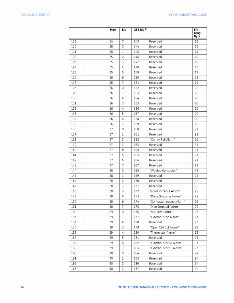
46 MM200 MOTOR MANAGEMENT SYSTEM – COMMUNICATIONS GUIDE
FIELDBUS INTERFACE COMMUNICATIONS GUIDE
119 24 7 143 Reserved 18
120 25 0 144 Reserved 19
121 25 1 145 Reserved 19
122 25 2 146 Reserved 19
123 25 3 147 Reserved 19
124 25 4 148 Reserved 19
125 25 5 149 Reserved 19
126 25 6 150 Reserved 19
127 25 7 151 Reserved 19
128 26 0 152 Reserved 20
129 26 1 153 Reserved 20
130 26 2 154 Reserved 20
131 26 3 155 Reserved 20
132 26 4 156 Reserved 20
133 26 5 157 Reserved 20
134 26 6 158 Reserved 20
135 26 7 159 Reserved 20
136 27 0 160 Reserved 21
137 27 1 161 Reserved 21
138 27 2 162 "Comm Fail Alarm" 21
139 27 3 163 Reserved 21
140 27 4 164 Reserved 21
141 27 5 165 Reserved 21
142 27 6 166 Reserved 21
143 27 7 167 Reserved 21
144 28 0 168 "Welded Contactor" 22
145 28 1 169 Reserved 22
146 28 2 170 Reserved 22
147 28 3 171 Reserved 22
148 28 4 172 "Load Increase Alarm" 22
149 28 5 173 "Drive Greasing Alarm" 22
150 28 6 174 "Contactor Inspect Alarm" 22
151 28 7 175 "Max Stopped Alarm" 22
152 29 0 176 "Aux U/V Alarm" 23
153 29 1 177 "External Stop Alarm" 23
154 29 2 178 Reserved 23
155 29 3 179 "Open Ctrl Cct Alarm" 23
156 29 4 180 "Thermistor Alarm" 23
157 29 5 181 Reserved 23
158 29 6 182 "External Start A Alarm" 23
159 29 7 183 "External Start B Alarm" 23
160 30 0 184 Reserved 24
161 30 1 185 Reserved 24
162 30 2 186 Reserved 24
163 30 3 187 Reserved 24
Byte Bit GSE Bit # Ext. Diag Byte
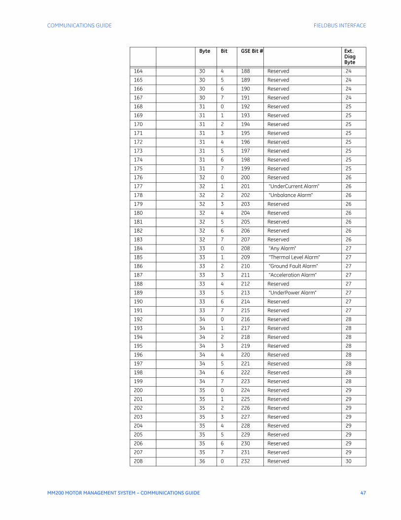
COMMUNICATIONS GUIDE FIELDBUS INTERFACE
MM200 MOTOR MANAGEMENT SYSTEM – COMMUNICATIONS GUIDE 47
164 30 4 188 Reserved 24
165 30 5 189 Reserved 24
166 30 6 190 Reserved 24
167 30 7 191 Reserved 24
168 31 0 192 Reserved 25
169 31 1 193 Reserved 25
170 31 2 194 Reserved 25
171 31 3 195 Reserved 25
172 31 4 196 Reserved 25
173 31 5 197 Reserved 25
174 31 6 198 Reserved 25
175 31 7 199 Reserved 25
176 32 0 200 Reserved 26
177 32 1 201 "UnderCurrent Alarm" 26
178 32 2 202 "Unbalance Alarm" 26
179 32 3 203 Reserved 26
180 32 4 204 Reserved 26
181 32 5 205 Reserved 26
182 32 6 206 Reserved 26
183 32 7 207 Reserved 26
184 33 0 208 "Any Alarm" 27
185 33 1 209 "Thermal Level Alarm" 27
186 33 2 210 "Ground Fault Alarm" 27
187 33 3 211 "Acceleration Alarm" 27
188 33 4 212 Reserved 27
189 33 5 213 "UnderPower Alarm" 27
190 33 6 214 Reserved 27
191 33 7 215 Reserved 27
192 34 0 216 Reserved 28
193 34 1 217 Reserved 28
194 34 2 218 Reserved 28
195 34 3 219 Reserved 28
196 34 4 220 Reserved 28
197 34 5 221 Reserved 28
198 34 6 222 Reserved 28
199 34 7 223 Reserved 28
200 35 0 224 Reserved 29
201 35 1 225 Reserved 29
202 35 2 226 Reserved 29
203 35 3 227 Reserved 29
204 35 4 228 Reserved 29
205 35 5 229 Reserved 29
206 35 6 230 Reserved 29
207 35 7 231 Reserved 29
208 36 0 232 Reserved 30
Byte Bit GSE Bit # Ext. Diag Byte
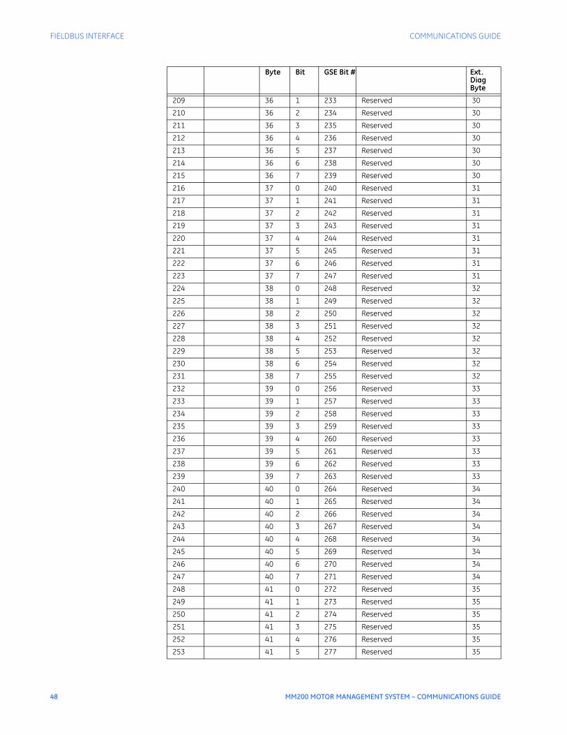
48 MM200 MOTOR MANAGEMENT SYSTEM – COMMUNICATIONS GUIDE
FIELDBUS INTERFACE COMMUNICATIONS GUIDE
209 36 1 233 Reserved 30
210 36 2 234 Reserved 30
211 36 3 235 Reserved 30
212 36 4 236 Reserved 30
213 36 5 237 Reserved 30
214 36 6 238 Reserved 30
215 36 7 239 Reserved 30
216 37 0 240 Reserved 31
217 37 1 241 Reserved 31
218 37 2 242 Reserved 31
219 37 3 243 Reserved 31
220 37 4 244 Reserved 31
221 37 5 245 Reserved 31
222 37 6 246 Reserved 31
223 37 7 247 Reserved 31
224 38 0 248 Reserved 32
225 38 1 249 Reserved 32
226 38 2 250 Reserved 32
227 38 3 251 Reserved 32
228 38 4 252 Reserved 32
229 38 5 253 Reserved 32
230 38 6 254 Reserved 32
231 38 7 255 Reserved 32
232 39 0 256 Reserved 33
233 39 1 257 Reserved 33
234 39 2 258 Reserved 33
235 39 3 259 Reserved 33
236 39 4 260 Reserved 33
237 39 5 261 Reserved 33
238 39 6 262 Reserved 33
239 39 7 263 Reserved 33
240 40 0 264 Reserved 34
241 40 1 265 Reserved 34
242 40 2 266 Reserved 34
243 40 3 267 Reserved 34
244 40 4 268 Reserved 34
245 40 5 269 Reserved 34
246 40 6 270 Reserved 34
247 40 7 271 Reserved 34
248 41 0 272 Reserved 35
249 41 1 273 Reserved 35
250 41 2 274 Reserved 35
251 41 3 275 Reserved 35
252 41 4 276 Reserved 35
253 41 5 277 Reserved 35
Byte Bit GSE Bit # Ext. Diag Byte

COMMUNICATIONS GUIDE FIELDBUS INTERFACE
MM200 MOTOR MANAGEMENT SYSTEM – COMMUNICATIONS GUIDE 49
254 41 6 278 Reserved 35
255 41 7 279 Reserved 35
256 42 0 280 Reserved 36
257 42 1 281 Reserved 36
258 42 2 282 Reserved 36
259 42 3 283 Reserved 36
260 42 4 284 Reserved 36
261 42 5 285 "HW Stop" 36
262 42 6 286 "Field Stop" 36
263 42 7 287 "MCC Stop" 36
264 43 0 288 Reserved 37
265 43 1 289 Reserved 37
266 43 2 290 Reserved 37
267 43 3 291 Reserved 37
268 43 4 292 Reserved 37
269 43 5 293 Reserved 37
270 43 6 294 Reserved 37
271 43 7 295 Reserved 37
272 44 0 296 "Forward Limit" 38
273 44 1 297 "Reverse Limit" 38
274 44 2 298 Reserved 38
275 44 3 299 Reserved 38
276 44 4 300 Reserved 38
277 44 5 301 Reserved 38
278 44 6 302 Reserved 38
279 44 7 303 Reserved 38
280 45 0 304 "Any Stop" 39
281 45 1 305 Reserved 39
282 45 2 306 Reserved 39
283 45 3 307 Reserved 39
284 45 4 308 Reserved 39
285 45 5 309 Reserved 39
286 45 6 310 Reserved 39
287 45 7 311 Reserved 39
Byte Bit GSE Bit # Ext. Diag Byte

50 MM200 MOTOR MANAGEMENT SYSTEM – COMMUNICATIONS GUIDE
FIELDBUS INTERFACE COMMUNICATIONS GUIDE
DeviceNet protocolTo enable the DeviceNet physical interface, ensure that switches 1 and 2 of the DIP switch communications card (on the CPU) are on. The external connections through the fieldbus interface are as follows.
Table 19: Fieldbus interface external connections (DeviceNet)
The Modbus status (MS) and network status (NS) LEDs indicate the status of the Fieldbus interface.
Table 20: DeviceNet LED indications
When used for DeviceNet, the fieldbus port has the following characteristics.• Baud rate: 125, 250, and 500 kbps• MAC ID: 0 to 63• Vendor ID: 928• Product Code: 0x4D47• Message types: poll, and explicit messaging
NOTE
NOTE: The ODVA cable assembly length (0.4 metre) must be considered when calculating the network drop length budget to the node.
DeviceNet powersupply configuration
The DeviceNet port uses external voltage to power the electronics. The figures below show the configuration of the the comms board option/power supply switch.
NOTE
NOTE: DeviceNet supports external power only.
Path Connection (external) Wire color
V– Pin 3, CAN_GND Black
L Pin 2, CAN_L Blue
C Pin 5, CAN_SHLD Bare
H Pin 7, CAN_H White
V+ Pin 9, CAN_V Red
LED LED operation Description
MS Green on, red on, green on Device self-test
Flashing green Device in standby state
Green on Device operational
Flashing red Recoverable fault
Red on Unrecoverable fault
NS Flashing green Online, not connected
Green on Online, connected
Flashing red Connection timeout
Red on Critical link failure
Red and green Network access detected

COMMUNICATIONS GUIDE FIELDBUS INTERFACE
MM200 MOTOR MANAGEMENT SYSTEM – COMMUNICATIONS GUIDE 51
Figure 9: Comms board power supply configuration
Table 21: SW1 switch settings
NOTE
NOTE: Other switch combinations are NOT ALLOWED.
DeviceNet setup andconfiguration (typical)
Hardware SetupConsider the example of a DeviceNet network containing the following devices:• A computer running RSNetWorx™ for DeviceNet software• A 1747-SDN-communication module interfacing an SLC 500 processor with the
DeviceNet network• 1770 KFD RS232 to DeviceNet module• MM200 Relay.
Wiring up the network
NOTE
NOTE: Ensure that power to the devices is switched off while making the connections. Make sure each end of the DeviceNet trunk cable is properly terminated with a 120-ohm resistor.
1. Connect the RS-232 connector on the 1770-KFD-communication interface module to one of the serial ports on your computer workstation (COM1).
Protocol Options
SW1 SW2 SW3 SW4
DeviceNet ON ON OFF OFF
Profibus OFF OFF ON ON
Supply Options
SW5 SW6 SW7 SW8
External OFF OFF ON ON
EXTERNALPOWER SUPPLY
ON
888846A2.CDR
1 2 3 4 5 6 7 8
= switch position
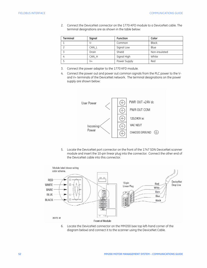
52 MM200 MOTOR MANAGEMENT SYSTEM – COMMUNICATIONS GUIDE
FIELDBUS INTERFACE COMMUNICATIONS GUIDE
2. Connect the DeviceNet connector on the 1770-KFD module to a DeviceNet cable. The terminal designations are as shown in the table below:
3. Connect the power adapter to the 1770 KFD module.4. Connect the power out and power out common signals from the PLC power to the V-
and V+ terminals of the DeviceNet network. The terminal designations on the power supply are shown below:
5. Locate the DeviceNet port connector on the front of the 1747 SDN DeviceNet scanner module and insert the 10-pin linear plug into the connector. Connect the other end of the DeviceNet cable into this connector.
6. Locate the DeviceNet connector on the MM200 (see top left-hand corner of the diagram below) and connect it to the scanner using the DeviceNet Cable.
Terminal Signal Function Color
1 V- Common Black
2 CAN_L Signal Low Blue
3 Drain Shield Non-insulated
4 CAN_H Signal High White
5 V+ Power Supply Red
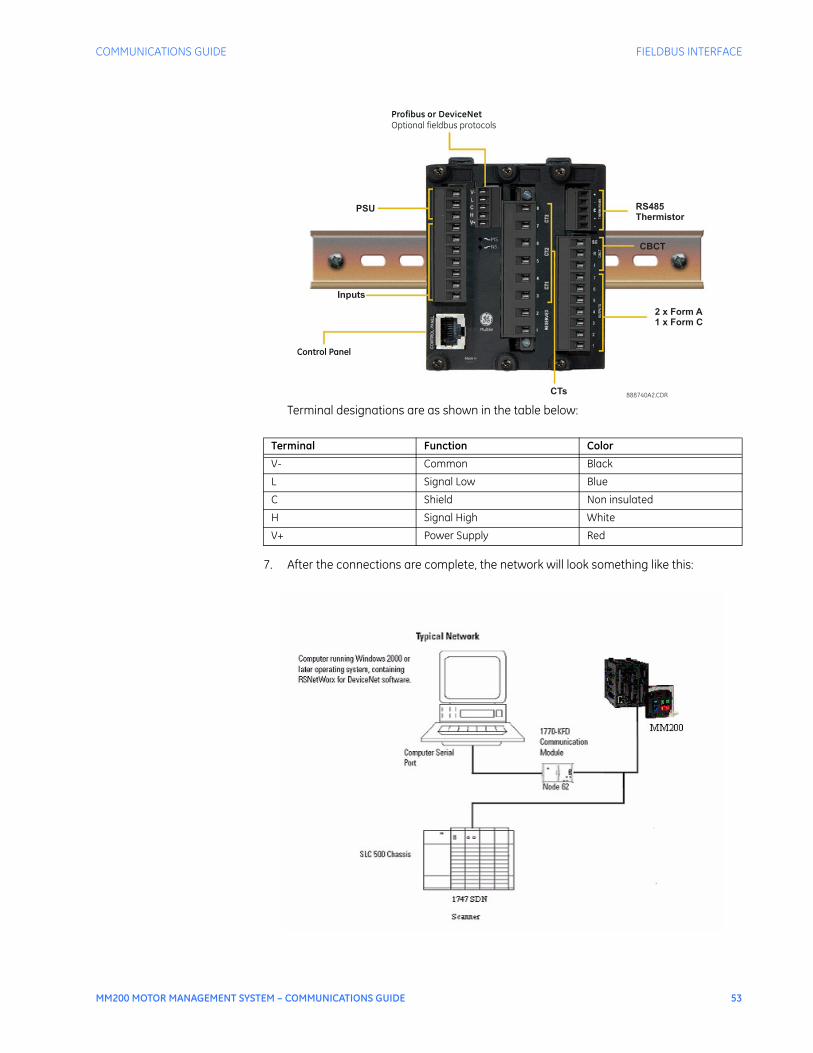
COMMUNICATIONS GUIDE FIELDBUS INTERFACE
MM200 MOTOR MANAGEMENT SYSTEM – COMMUNICATIONS GUIDE 53
Terminal designations are as shown in the table below:
7. After the connections are complete, the network will look something like this:
Terminal Function Color
V- Common Black
L Signal Low Blue
C Shield Non insulated
H Signal High White
V+ Power Supply Red
Control Panel
Profibus or DeviceNet
Optional fieldbus protocols
888740A2.CDRCTs
PSU
Inputs
RS485Thermistor
CBCT
2 x Form A1 x Form C
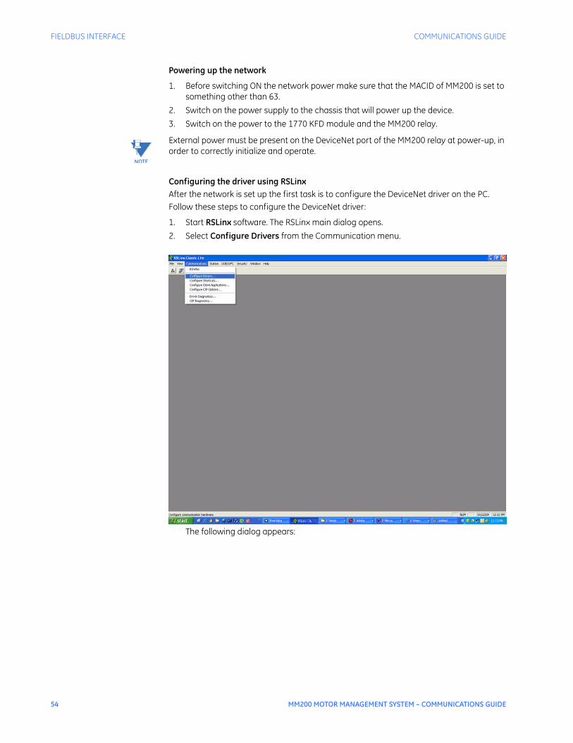
54 MM200 MOTOR MANAGEMENT SYSTEM – COMMUNICATIONS GUIDE
FIELDBUS INTERFACE COMMUNICATIONS GUIDE
Powering up the network
1. Before switching ON the network power make sure that the MACID of MM200 is set to something other than 63.
2. Switch on the power supply to the chassis that will power up the device.3. Switch on the power to the 1770 KFD module and the MM200 relay.
NOTE
NOTE: External power must be present on the DeviceNet port of the MM200 relay at power-up, in order to correctly initialize and operate.
Configuring the driver using RSLinxAfter the network is set up the first task is to configure the DeviceNet driver on the PC. Follow these steps to configure the DeviceNet driver:
1. Start RSLinx software. The RSLinx main dialog opens.2. Select Configure Drivers from the Communication menu.
The following dialog appears:

COMMUNICATIONS GUIDE FIELDBUS INTERFACE
MM200 MOTOR MANAGEMENT SYSTEM – COMMUNICATIONS GUIDE 55
3. Select DeviceNet Drivers from the above pull-down menu and Click Add/New. The following menu will appear:
4. Select the Allen-Bradley™ 1770-KFD driver. The Driver Configuration dialog appears:

56 MM200 MOTOR MANAGEMENT SYSTEM – COMMUNICATIONS GUIDE
FIELDBUS INTERFACE COMMUNICATIONS GUIDE
5. Configure the driver using the settings above as a guide, and click on OK. The software takes a few seconds to configure the driver. When it is complete, the following prompt appears:
NOTE
NOTE: This dialog will only appear if there is at least one active node on the DeviceNet network. So ensure that the network power is on and that the MM200 relay and the scanner are on the DeviceNet network.
6. Select the default driver name, 1770-KFD-1, and click OK. Close the RSLinx software.
Configuring the network and going onlineThe next step is to configure the network with RSNetWorx for DeviceNet software using the driver that was just configured.Follow these steps to set up an online connection to the DeviceNet network, using the 1770-KFD driver:
1. Start RSNetWorx for DeviceNet software. The following dialog appears:
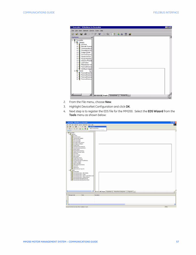
COMMUNICATIONS GUIDE FIELDBUS INTERFACE
MM200 MOTOR MANAGEMENT SYSTEM – COMMUNICATIONS GUIDE 57
2. From the File menu, choose New.3. Highlight DeviceNet Configuration and click OK. 4. Next step is to register the EDS file for the MM200. Select the EDS Wizard from the
Tools menu as shown below:

58 MM200 MOTOR MANAGEMENT SYSTEM – COMMUNICATIONS GUIDE
FIELDBUS INTERFACE COMMUNICATIONS GUIDE
5. Press Next
6. Click on Register an EDS file:

COMMUNICATIONS GUIDE FIELDBUS INTERFACE
MM200 MOTOR MANAGEMENT SYSTEM – COMMUNICATIONS GUIDE 59
7. Browse and select the EDS file for MM200. Make sure that the Icon file is present in the same folder as the EDS file.
8. Save the DeviceNet file after registering the EDS file. Close the RSNetworx software and reboot the PC.
NOTE
NOTE: You must reboot the PC to make sure that the EDS file is registered correctly.
9. After rebooting the PC, restart the RSNetworx software and open the recently saved DeviceNet file.
10. Click Online on the toolbar. List of the available drivers in RSLinx software appears, as shown below:
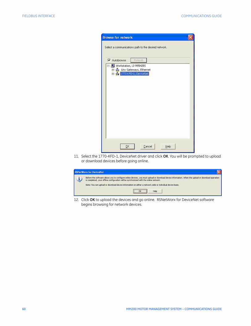
60 MM200 MOTOR MANAGEMENT SYSTEM – COMMUNICATIONS GUIDE
FIELDBUS INTERFACE COMMUNICATIONS GUIDE
11. Select the 1770-KFD-1, DeviceNet driver and click OK. You will be prompted to upload or download devices before going online.
12. Click OK to upload the devices and go online. RSNetWorx for DeviceNet software begins browsing for network devices.
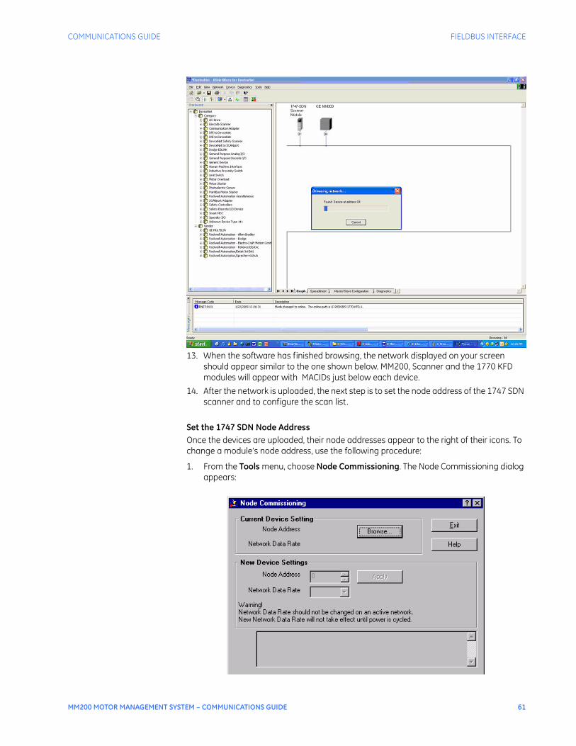
COMMUNICATIONS GUIDE FIELDBUS INTERFACE
MM200 MOTOR MANAGEMENT SYSTEM – COMMUNICATIONS GUIDE 61
13. When the software has finished browsing, the network displayed on your screen should appear similar to the one shown below. MM200, Scanner and the 1770 KFD modules will appear with MACIDs just below each device.
14. After the network is uploaded, the next step is to set the node address of the 1747 SDN scanner and to configure the scan list.
Set the 1747 SDN Node AddressOnce the devices are uploaded, their node addresses appear to the right of their icons. To change a module’s node address, use the following procedure:
1. From the Tools menu, choose Node Commissioning. The Node Commissioning dialog appears:

62 MM200 MOTOR MANAGEMENT SYSTEM – COMMUNICATIONS GUIDE
FIELDBUS INTERFACE COMMUNICATIONS GUIDE
2. Click Browse. The Device Selection dialog appears:
3. Select the 1770-KFD driver. The devices on the network appear in the right panel of the dialog:
4. From the right panel,select the device you are commissioning and click OK. The Node Commissioning dialog appears with the current settings for your 1747-SDN module. The dialog should look similar to the one shown below:
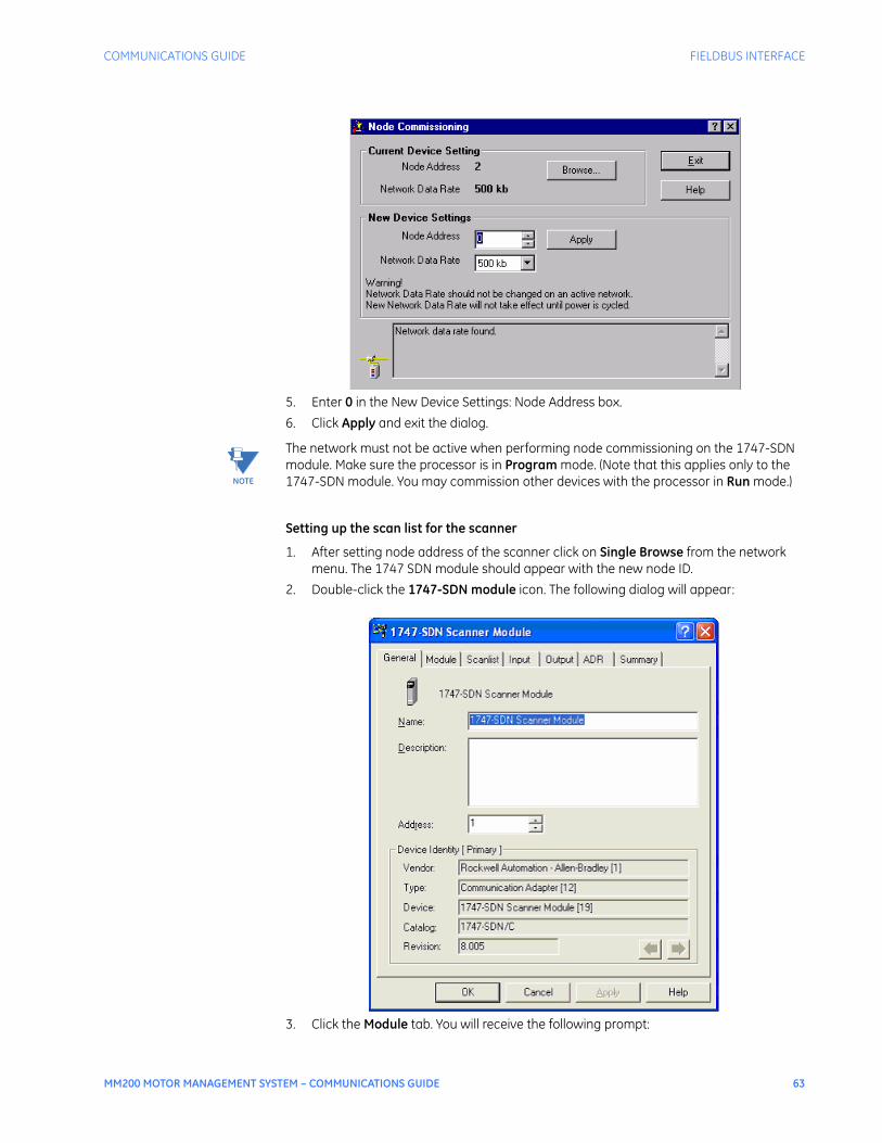
COMMUNICATIONS GUIDE FIELDBUS INTERFACE
MM200 MOTOR MANAGEMENT SYSTEM – COMMUNICATIONS GUIDE 63
5. Enter 0 in the New Device Settings: Node Address box.6. Click Apply and exit the dialog.
NOTE
NOTE: The network must not be active when performing node commissioning on the 1747-SDN module. Make sure the processor is in Program mode. (Note that this applies only to the 1747-SDN module. You may commission other devices with the processor in Run mode.)
Setting up the scan list for the scanner
1. After setting node address of the scanner click on Single Browse from the network menu. The 1747 SDN module should appear with the new node ID.
2. Double-click the 1747-SDN module icon. The following dialog will appear:
3. Click the Module tab. You will receive the following prompt:

64 MM200 MOTOR MANAGEMENT SYSTEM – COMMUNICATIONS GUIDE
FIELDBUS INTERFACE COMMUNICATIONS GUIDE
4. Click Upload. After uploading, the following dialog will appear:
5. Verify the 1747-SDN-module slot number is correct for the system.6. Select the Scanlist tab. The MM200 relay will be seen in the Available Devices list. 7. Verify that the Automap on Add box is NOT checked.
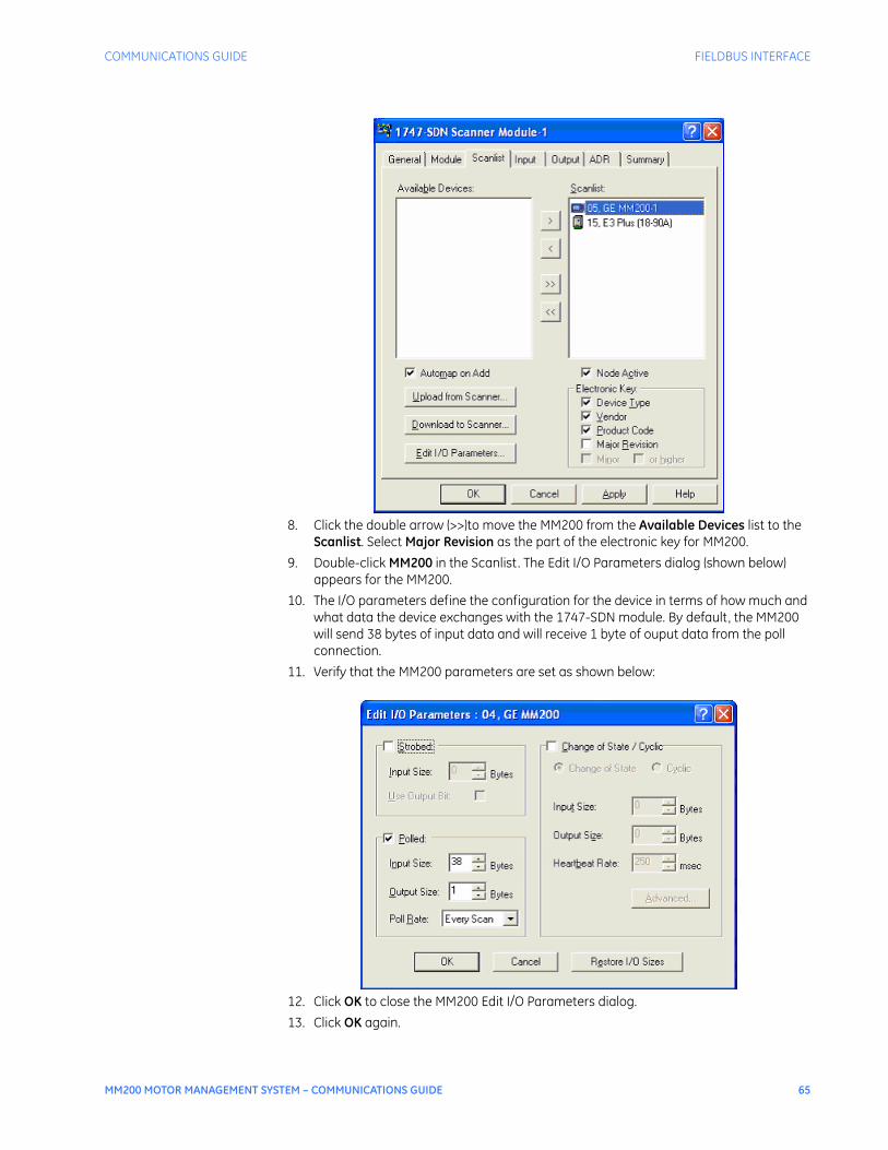
COMMUNICATIONS GUIDE FIELDBUS INTERFACE
MM200 MOTOR MANAGEMENT SYSTEM – COMMUNICATIONS GUIDE 65
8. Click the double arrow (>>)to move the MM200 from the Available Devices list to the Scanlist. Select Major Revision as the part of the electronic key for MM200.
9. Double-click MM200 in the Scanlist. The Edit I/O Parameters dialog (shown below) appears for the MM200.
10. The I/O parameters define the configuration for the device in terms of how much and what data the device exchanges with the 1747-SDN module. By default, the MM200 will send 38 bytes of input data and will receive 1 byte of ouput data from the poll connection.
11. Verify that the MM200 parameters are set as shown below:
12. Click OK to close the MM200 Edit I/O Parameters dialog.13. Click OK again.

66 MM200 MOTOR MANAGEMENT SYSTEM – COMMUNICATIONS GUIDE
FIELDBUS INTERFACE COMMUNICATIONS GUIDE
14. You will be prompted to download the changes to the 1747-SDN module:
15. Click Yes to download the new configuration. The next step is to enable the ADR for the MM200 relay.
DeviceNet setup andconfiguration (ADR)
Overview of ADRAuto-Device Replacement, or ADR, is feature of Allen-Bradley scanners that automates the replacement of a failed device on a DeviceNet network, returning it to the prior level of operation without having to use a software tool. It consists of two distinct features:Configuration Recovery, or CR, refers to the scanner's ability to store a device's configuration. With this feature enabled, the scanner will download this stored configuration to the device before it begins to exchange I/O data with that device.Auto Address Recovery, or AAR, refers to the ability of the scanner to change a device's node address from 63 (the default address) to that desired by the scanner. For example, when the scanner loses a connection to the device at node address #37, it will continually query the device's identity at node address #63. When a device is found that matches the Electronic Key of the devices that the scanner lost at node address #37, it will attempt to change its node address to node address #37. Upon success, the device's configuration will be downloaded.There are some restrictions fo keep in mind:• Both CR and AAR can only be used with devices that are in the scanlist of the scanner.• AAR can only be enabled for a device if CR is also enabled.• CR cannot be enabled for devices that have no writeable parameters.• AAR will not work for devices that do not support changing the node address over the
network. • In the MM200, only the contents of the A1 object are supported by ADR.Enabling ADR
NOTE
NOTE: Before proceeding to the next step ensure that the MM200 relay and the network are configured as desired. These configurations will be then stored in the scanner for the ADR feature.
1. Start RSNetworx and open the existing project file. If no project exists, create a new file.
2. Browse or go On-Line with a network that is configured as desired3. Once the network appears on the screen, Right Click the mouse (Do NOT right click on
a device).4. Click Upload from Network.5. Save File when all devices have been uploaded.6. Double Click on Scanner.7. Click on the ADR tab.8. Click on the Enable Auto Address Recovery box.
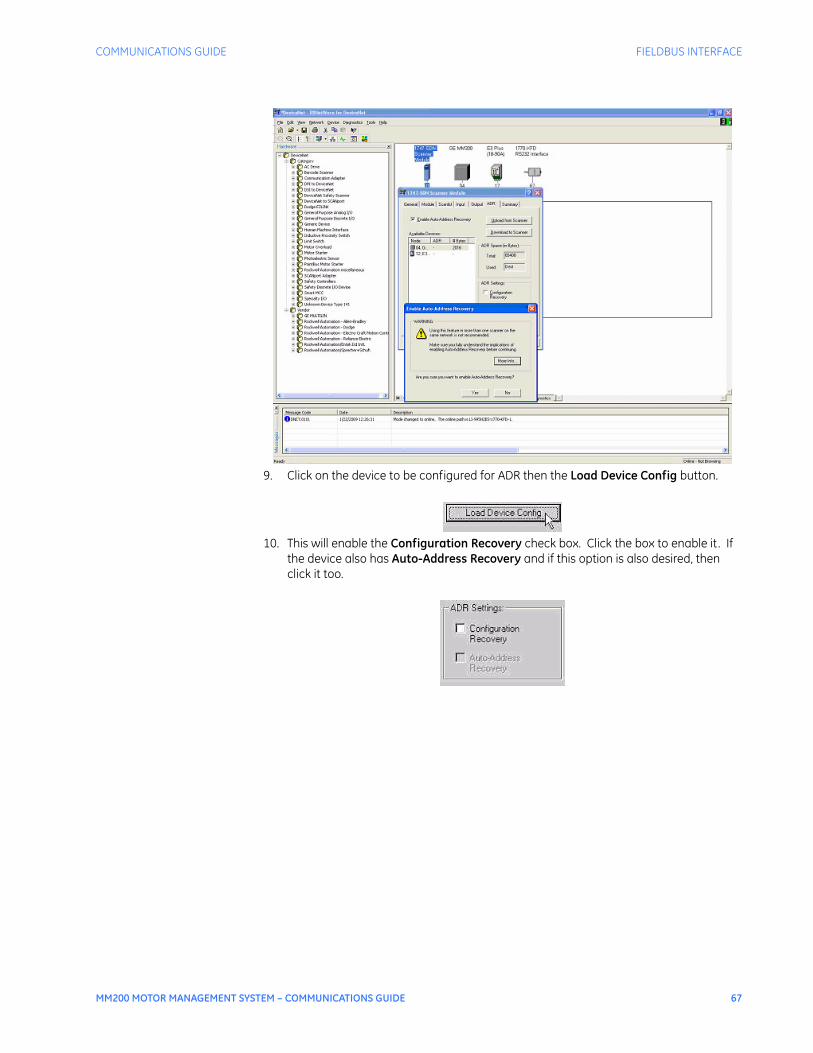
COMMUNICATIONS GUIDE FIELDBUS INTERFACE
MM200 MOTOR MANAGEMENT SYSTEM – COMMUNICATIONS GUIDE 67
9. Click on the device to be configured for ADR then the Load Device Config button.
10. This will enable the Configuration Recovery check box. Click the box to enable it . If the device also has Auto-Address Recovery and if this option is also desired, then click it too.
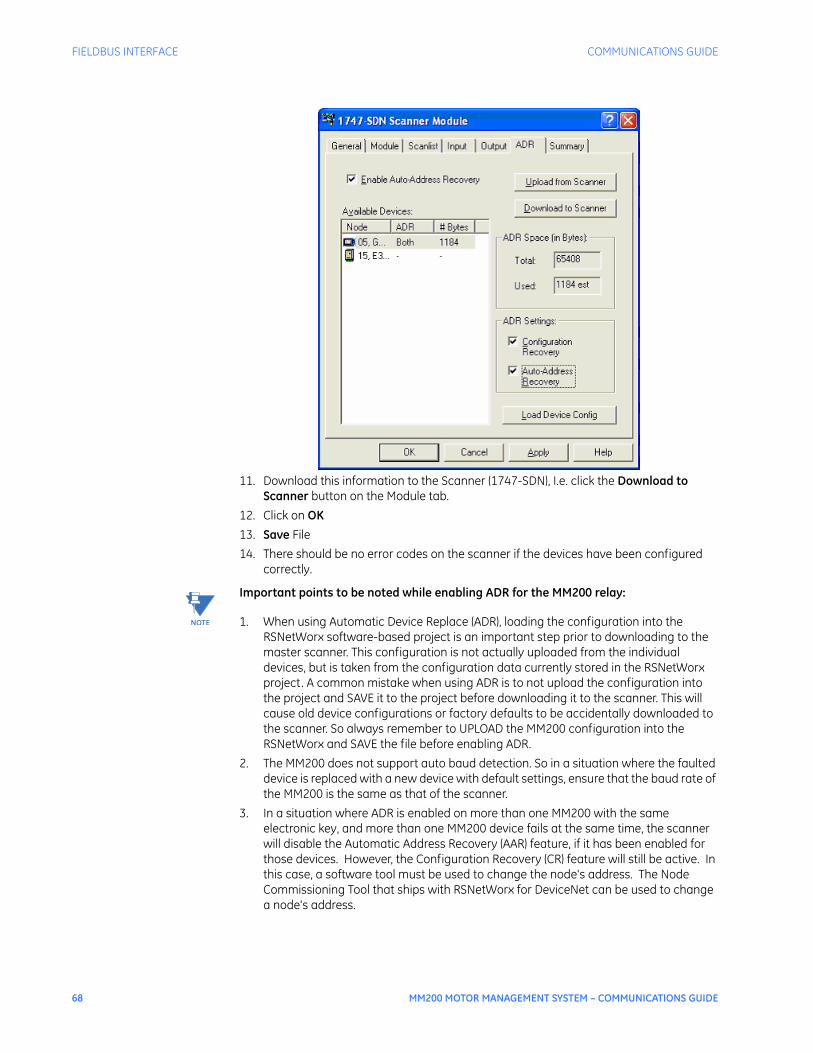
68 MM200 MOTOR MANAGEMENT SYSTEM – COMMUNICATIONS GUIDE
FIELDBUS INTERFACE COMMUNICATIONS GUIDE
11. Download this information to the Scanner (1747-SDN), I.e. click the Download to Scanner button on the Module tab.
12. Click on OK13. Save File14. There should be no error codes on the scanner if the devices have been configured
correctly.
NOTE
NOTE: Important points to be noted while enabling ADR for the MM200 relay:
1. When using Automatic Device Replace (ADR), loading the configuration into the RSNetWorx software-based project is an important step prior to downloading to the master scanner. This configuration is not actually uploaded from the individual devices, but is taken from the configuration data currently stored in the RSNetWorx project. A common mistake when using ADR is to not upload the configuration into the project and SAVE it to the project before downloading it to the scanner. This will cause old device configurations or factory defaults to be accidentally downloaded to the scanner. So always remember to UPLOAD the MM200 configuration into the RSNetWorx and SAVE the file before enabling ADR.
2. The MM200 does not support auto baud detection. So in a situation where the faulted device is replaced with a new device with default settings, ensure that the baud rate of the MM200 is the same as that of the scanner.
3. In a situation where ADR is enabled on more than one MM200 with the same electronic key, and more than one MM200 device fails at the same time, the scanner will disable the Automatic Address Recovery (AAR) feature, if it has been enabled for those devices. However, the Configuration Recovery (CR) feature will still be active. In this case, a software tool must be used to change the node's address. The Node Commissioning Tool that ships with RSNetWorx for DeviceNet can be used to change a node's address.

COMMUNICATIONS GUIDE FIELDBUS INTERFACE
MM200 MOTOR MANAGEMENT SYSTEM – COMMUNICATIONS GUIDE 69
4. Considering the scanner’s limited memory for storage of the ADR configuration, more than one scanner will be required if there are many MM200 relays in the DeviceNet network.
DeviceNetCommunications
The device profile is an extension of the Communications Adapter Device Profile (0xC0). It is a group 2 only server. The MAC ID and baud rate are programmable through the EnerVista MM200 Setup software. The MM200 supports the following DeviceNet object classes.
The MM200 supports poll and explicit messaging types.The Poll function consumes one byte of control data (described under User Object Class B1h, Instance 01h, Attribute 01h) and produces 38 bytes of status and metering data as described in User Object Class A0h, Instance 01h, Attribute 01h.USINT, UINT, UDINT and DINT, stated in this document, stand for the following data types :USINT = Unsigned integer byteUINT = Unsigned integer wordUDINT = Unsigned integer double wordDINT = Signed integer double word
Poll data The Polling function consumes one byte of control data and produces 38 bytes of status and metering data as described in User Object Class A0h, Instance 01h, Attribute 01h. The control data format is as follows:
Table 22: Data Value, polled output data
Commands are actioned on a change in Output data.
CLASS OBJECT
01H Identify
02H Message Router
03H DeviceNet
05H Connection
A0H Generic Data - Polling/Explicit
B1H Explicit Control Writes
B0H Analog Data - Explicit
A1H Configuration Data - Explicit
A2H Analog Data - Explicit
VALUE DESCRIPTION
1 Reset
2 Lockout Reset
3 Stop
4 Start A
5 Start B
66 Clear Last Trip Data Prompt
68 Clear Counters
71 Clear Maintenance Timer
73 Reset Motor Information
74 Auto Mode
75 Manual Mode

70 MM200 MOTOR MANAGEMENT SYSTEM – COMMUNICATIONS GUIDE
FIELDBUS INTERFACE COMMUNICATIONS GUIDE
The example diagram below shows the MM200 polled I/O data read/written using a DeviceNet master simulator. In this example, the "Start A" command has been sent via Output data. In reading the Input data and interpreting the first byte value (98h) based on the data format for that byte (FC129) the following is true:• Auto control is enabled• Contactor A is energized• Drive Available is trueIn the event that there is a communication fault, and a pre-fault polled output command caused the MM200 to start a motor, the motor will continue to run even after the communication fault.
Figure 10: DeviceNet polled I/O data
Identity Object (ClassCode 01H)
Table 23: Identity Object, Class Code 01h, Services:
Table 24: Identity Object, Class Code 01h, Attributes:
Table 25: Identity Object, Class Code 01h, Instance 01h, Attributes:
Message Router (ClassCode 02H)
The message router (class code 2) object provides a messaging connection point through which a client may address a service to any object or instance residing in the physical device. There is no external visible interface to the message router object.
CODE SERVICES AVAILABLE TO THIS OBJECT
NAME DESCRIPTION
0x05 Reset Reset the device to power up configuration
0x0E Get_Attribute_Single Returns the contents of the given attribute
ATTRIBUTE ACCESS NAME/DESCRIPTION DATA TYPE VALUE
01h Get Revision of Identity Object UINT 1
ATTRIBUTE ACCESS NAME/DESCRIPTION DATA TYPE VALUE
01h Get Vendor ID UINT 928
02h Get Device Type UINT 12
03h Get Product Code UINT 0x4D47
04h Get Revision (Major, Minor) USINT 1.1

COMMUNICATIONS GUIDE FIELDBUS INTERFACE
MM200 MOTOR MANAGEMENT SYSTEM – COMMUNICATIONS GUIDE 71
DeviceNet Object(Class Code 03H)
Table 26: Identity Object, Class Code 03h, Services:
Table 27: Identity Object, Class Code 03h, Attributes:
Table 28: Identity Object, Class Code 03h, Instance 01h, Attributes:
DeviceNet ConnectionObject (Class Code
05H)
Table 29: Connection Object, Class Code 05h, Services:
CODE SERVICES AVAILABLE TO THIS OBJECT
NAME DESCRIPTION
0x0E Get_Attribute_Single Returns the contents of the given attribute
0x10 Set_Attribute_Single Sets the contents of the given attribute
ATTRIBUTE ACCESS NAME/DESCRIPTION DATA TYPE VALUE
01h Get Revision of DeviceNet Object UINT 1
ATTRIBUTE ACCESS NAME/DESCRIPTION
DATA TYPE VALUE
01h Get MAC ID USINT 0 to 63
02h Get/Set Baud Rate USINT 0 = 125 kbps
1 = 250 kbps
2 = 500 kbps
05h Get Allocation Choice BYTE Bit 0: Explicit Messaging
Bit 1: polled I/O
Bit 6: acknowledge suppression
Master’s MAC ID USINT 0 to 63: address; 255 = unallocated
CODE SERVICES AVAILABLE TO THIS OBJECT
NAME DESCRIPTION
0x05 Reset Reset the device to power up configuration
0x0E Get_Attribute_Single Returns the contents of the given attribute
0x10 Set_Attribute_Single Sets the contents of the given attribute
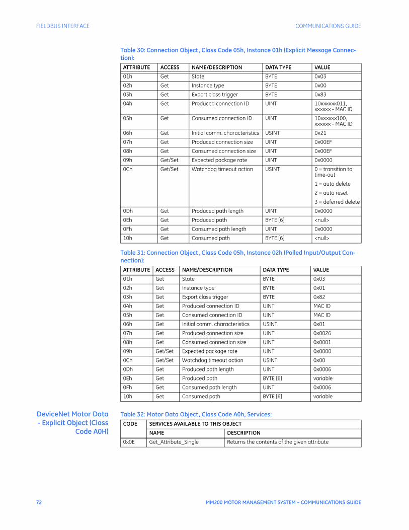
72 MM200 MOTOR MANAGEMENT SYSTEM – COMMUNICATIONS GUIDE
FIELDBUS INTERFACE COMMUNICATIONS GUIDE
Table 30: Connection Object, Class Code 05h, Instance 01h (Explicit Message Connec-tion):
Table 31: Connection Object, Class Code 05h, Instance 02h (Polled Input/Output Con-nection):
DeviceNet Motor Data- Explicit Object (Class
Code A0H)
Table 32: Motor Data Object, Class Code A0h, Services:
ATTRIBUTE ACCESS NAME/DESCRIPTION DATA TYPE VALUE
01h Get State BYTE 0x03
02h Get Instance type BYTE 0x00
03h Get Export class trigger BYTE 0x83
04h Get Produced connection ID UINT 10xxxxxx011, xxxxxx - MAC ID
05h Get Consumed connection ID UINT 10xxxxxx100, xxxxxx - MAC ID
06h Get Initial comm. characteristics USINT 0x21
07h Get Produced connection size UINT 0x00EF
08h Get Consumed connection size UINT 0x00EF
09h Get/Set Expected package rate UINT 0x0000
0Ch Get/Set Watchdog timeout action USINT 0 = transition to time-out
1 = auto delete
2 = auto reset
3 = deferred delete
0Dh Get Produced path length UINT 0x0000
0Eh Get Produced path BYTE [6] <null>
0Fh Get Consumed path length UINT 0x0000
10h Get Consumed path BYTE [6] <null>
ATTRIBUTE ACCESS NAME/DESCRIPTION DATA TYPE VALUE
01h Get State BYTE 0x03
02h Get Instance type BYTE 0x01
03h Get Export class trigger BYTE 0x82
04h Get Produced connection ID UINT MAC ID
05h Get Consumed connection ID UINT MAC ID
06h Get Initial comm. characteristics USINT 0x01
07h Get Produced connection size UINT 0x0026
08h Get Consumed connection size UINT 0x0001
09h Get/Set Expected package rate UINT 0x0000
0Ch Get/Set Watchdog timeout action USINT 0x00
0Dh Get Produced path length UINT 0x0006
0Eh Get Produced path BYTE [6] variable
0Fh Get Consumed path length UINT 0x0006
10h Get Consumed path BYTE [6] variable
CODE SERVICES AVAILABLE TO THIS OBJECT
NAME DESCRIPTION
0x0E Get_Attribute_Single Returns the contents of the given attribute
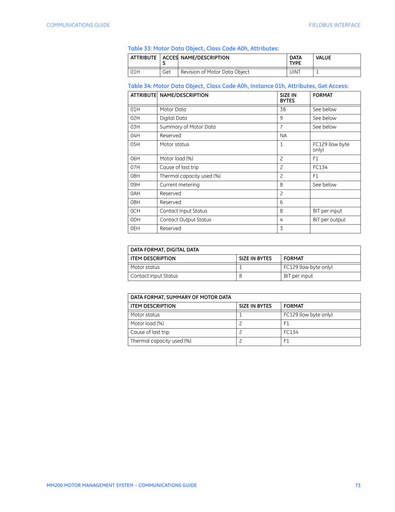
COMMUNICATIONS GUIDE FIELDBUS INTERFACE
MM200 MOTOR MANAGEMENT SYSTEM – COMMUNICATIONS GUIDE 73
Table 33: Motor Data Object, Class Code A0h, Attributes:
Table 34: Motor Data Object, Class Code A0h, Instance 01h, Attributes, Get Access:
ATTRIBUTE ACCESS
NAME/DESCRIPTION DATA TYPE
VALUE
01H Get Revision of Motor Data Object UINT 1
ATTRIBUTE NAME/DESCRIPTION SIZE IN BYTES
FORMAT
01H Motor Data 38 See below
02H Digital Data 9 See below
03H Summary of Motor Data 7 See below
04H Reserved NA
05H Motor status 1 FC129 (low byte only)
06H Motor load (%) 2 F1
07H Cause of last trip 2 FC134
08H Thermal capacity used (%) 2 F1
09H Current metering 8 See below
0AH Reserved 2
0BH Reserved 6
0CH Contact Input Status 8 BIT per input
0DH Contact Output Status 4 BIT per output
0EH Reserved 3
DATA FORMAT, DIGITAL DATA
ITEM DESCRIPTION SIZE IN BYTES FORMAT
Motor status 1 FC129 (low byte only)
Contact Input Status 8 BIT per input
DATA FORMAT, SUMMARY OF MOTOR DATA
ITEM DESCRIPTION SIZE IN BYTES FORMAT
Motor status 1 FC129 (low byte only)
Motor load (%) 2 F1
Cause of last trip 2 FC134
Thermal capacity used (%) 2 F1
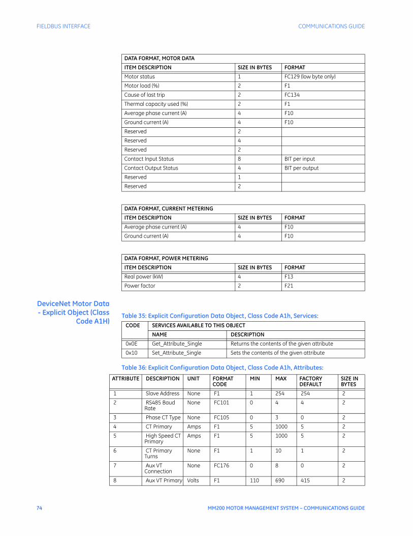
74 MM200 MOTOR MANAGEMENT SYSTEM – COMMUNICATIONS GUIDE
FIELDBUS INTERFACE COMMUNICATIONS GUIDE
DeviceNet Motor Data- Explicit Object (Class
Code A1H)Table 35: Explicit Configuration Data Object, Class Code A1h, Services:
Table 36: Explicit Configuration Data Object, Class Code A1h, Attributes:
DATA FORMAT, MOTOR DATA
ITEM DESCRIPTION SIZE IN BYTES FORMAT
Motor status 1 FC129 (low byte only)
Motor load (%) 2 F1
Cause of last trip 2 FC134
Thermal capacity used (%) 2 F1
Average phase current (A) 4 F10
Ground current (A) 4 F10
Reserved 2
Reserved 4
Reserved 2
Contact Input Status 8 BIT per input
Contact Output Status 4 BIT per output
Reserved 1
Reserved 2
DATA FORMAT, CURRENT METERING
ITEM DESCRIPTION SIZE IN BYTES FORMAT
Average phase current (A) 4 F10
Ground current (A) 4 F10
DATA FORMAT, POWER METERING
ITEM DESCRIPTION SIZE IN BYTES FORMAT
Real power (kW) 4 F13
Power factor 2 F21
CODE SERVICES AVAILABLE TO THIS OBJECT
NAME DESCRIPTION
0x0E Get_Attribute_Single Returns the contents of the given attribute
0x10 Set_Attribute_Single Sets the contents of the given attribute
ATTRIBUTE DESCRIPTION UNIT FORMAT CODE
MIN MAX FACTORY DEFAULT
SIZE IN BYTES
1 Slave Address None F1 1 254 254 2
2 RS485 Baud Rate
None FC101 0 4 4 2
3 Phase CT Type None FC105 0 3 0 2
4 CT Primary Amps F1 5 1000 5 2
5 High Speed CT Primary
Amps F1 5 1000 5 2
6 CT Primary Turns
None F1 1 10 1 2
7 Aux VT Connection
None FC176 0 8 0 2
8 Aux VT Primary Volts F1 110 690 415 2
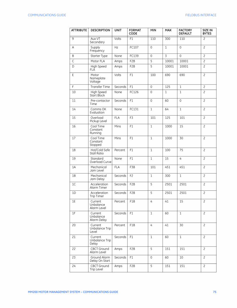
COMMUNICATIONS GUIDE FIELDBUS INTERFACE
MM200 MOTOR MANAGEMENT SYSTEM – COMMUNICATIONS GUIDE 75
9 Aux VT Secondary
Volts F1 110 300 110 2
A Supply Frequency
Hz FC107 0 1 0 2
B Starter Type None FC139 0 3 0 2
C Motor FLA Amps F2B 5 10001 10001 2
D High Speed FLA
Amps F2B 5 10001 10001 2
E Motor Nameplate Voltage
Volts F1 100 690 690 2
F Transfer Time Seconds F1 0 125 1 2
10 High Speed Start Block
None FC126 0 1 1 2
11 Pre-contactor Time
Seconds F1 0 60 0 2
14 Comms OK Evaluation
None FC131 1 64 1 2
15 Overload Pickup Level
FLA F3 101 125 101 2
16 Cool Time Constant Running
Mins F1 1 1000 15 2
17 Cool Time Constant Stopped
Mins F1 1 1000 30 2
18 Hot/Cold Safe Stall Ratio
Percent F1 1 100 75 2
19 Standard Overload Curve
None F1 1 15 4 2
1A Mechanical Jam Level
FLA F3B 101 451 451 2
1B Mechanical Jam Delay
Seconds F2 1 300 1 2
1C Acceleration Alarm Timer
Seconds F2B 5 2501 2501 2
1D Acceleration Trip Timer
Seconds F2B 5 2501 2501 2
1E Current Unbalance Alarm Level
Percent F1B 4 41 15 2
1F Current Unbalance Alarm Delay
Seconds F1 1 60 1 2
20 Current Unbalance Trip Level
Percent F1B 4 41 30 2
21 Current Unbalance Trip Delay
Seconds F1 1 60 1 2
22 CBCT Ground Alarm Level
Amps F2B 5 151 151 2
23 Ground Alarm Delay On Start
Seconds F1 0 60 10 2
24 CBCT Ground Trip Level
Amps F2B 5 151 151 2
ATTRIBUTE DESCRIPTION UNIT FORMAT CODE
MIN MAX FACTORY DEFAULT
SIZE IN BYTES

76 MM200 MOTOR MANAGEMENT SYSTEM – COMMUNICATIONS GUIDE
FIELDBUS INTERFACE COMMUNICATIONS GUIDE
25 Ground Trip Delay On Start
Seconds F2 0 100 0 2
26 Ground Alarm Delay On Run
Seconds F1 0 60 10 2
27 Ground Trip Delay On Run
Seconds F2 0 50 0 2
2D Lockout Reset None FC142 0 0xE000 0 2
2E Access Switch None FC142 0 0xE000 0 2
2F Field Permissive
None FC142 0 0xE000 0 2
30 Comms Permissive
None FC142 0 0xE000 0 2
31 Forward Limit None FC142 0 0xE000 0 2
32 Reverse Limit None FC142 0 0xE000 0 2
33 Remote Reset None FC142 0 0xE000 0 2
34 MCC Permissive
None FC142 0 0xE000 0 2
35 Hard Wired Start A
None FC142 0 0xE000 0 2
36 Hard Wired Start B
None FC142 0 0xE000 0 2
37 Hard Wired Stop
None FC142 0 0xE000 0 2
38 Hard Wired Permissive
None FC142 0 0xE000 0 2
39 Field Start A None FC142 0 0xE000 0 2
3A Field Start B None FC142 0 0xE000 0 2
3B Field Stop None FC142 0 0xE000 0 2
3C Contactor Status A
None FC142 0 0xE000 0 2
3D Contactor Status B
None FC142 0 0xE000 0 2
3E Auto/Manual Switch
None FC142 0 0xE000 0 2
3F Test Switch None FC142 0 0xE000 0 2
40 Self Test Action None FC111 0 1 0 2
41 Comms Start Ctrl
None FC126 0 1 0 2
42 Comms Stop Mode
None FC172 0 1 0 2
43 Hard Wired Start Ctrl
None FC126 0 1 0 2
44 Hard Wired Stop Mode
None FC172 0 1 0 2
45 Hard Wired Stop Actn
None FC174 0 1 0 2
46 Hard Wired 2W/3W
None FC173 0 1 1 2
47 Field Start Ctrl None FC126 0 1 0 2
48 Field Stop Mode
None FC172 0 1 0 2
49 Field Stop Action
None FC174 0 1 0 2
4A Field 2W/3W None FC173 0 1 1 2
ATTRIBUTE DESCRIPTION UNIT FORMAT CODE
MIN MAX FACTORY DEFAULT
SIZE IN BYTES
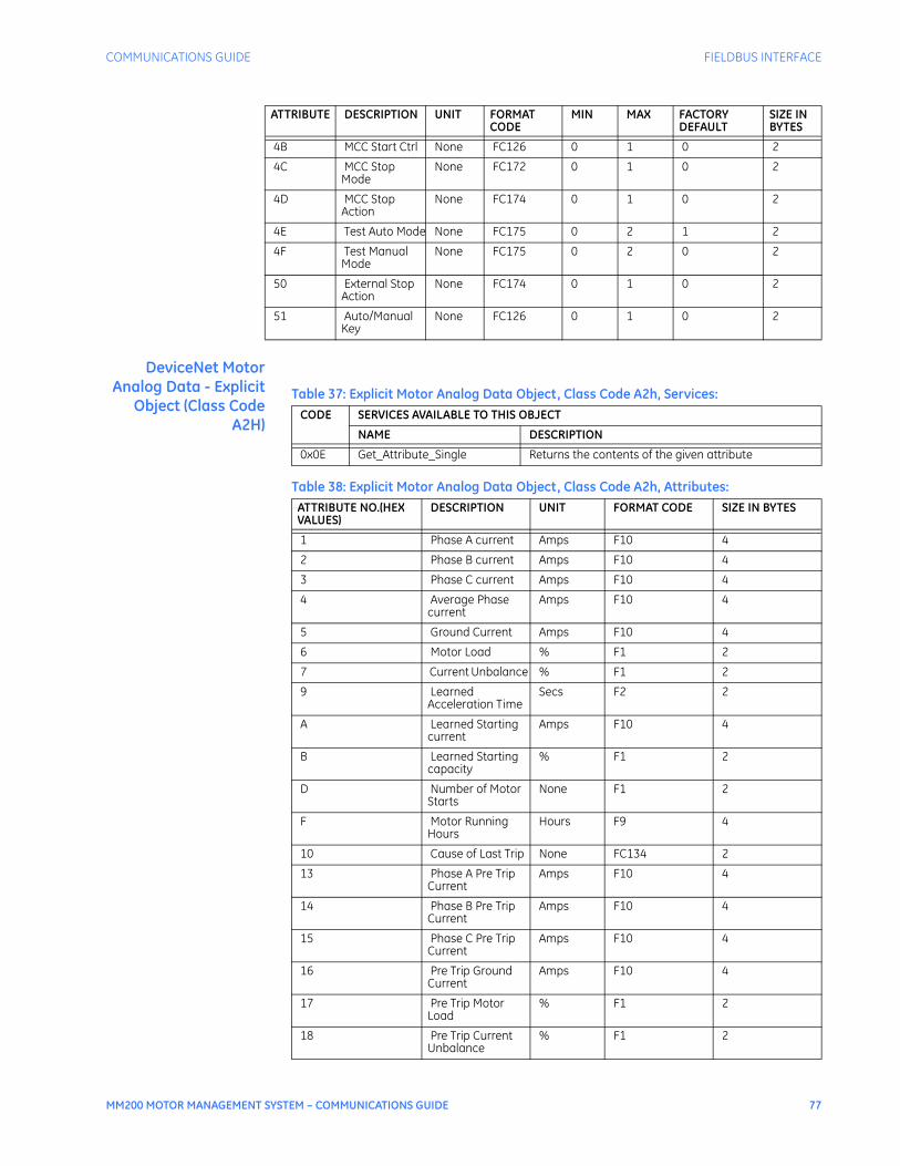
COMMUNICATIONS GUIDE FIELDBUS INTERFACE
MM200 MOTOR MANAGEMENT SYSTEM – COMMUNICATIONS GUIDE 77
DeviceNet MotorAnalog Data - Explicit
Object (Class CodeA2H)
Table 37: Explicit Motor Analog Data Object, Class Code A2h, Services:
Table 38: Explicit Motor Analog Data Object, Class Code A2h, Attributes:
4B MCC Start Ctrl None FC126 0 1 0 2
4C MCC Stop Mode
None FC172 0 1 0 2
4D MCC Stop Action
None FC174 0 1 0 2
4E Test Auto Mode None FC175 0 2 1 2
4F Test Manual Mode
None FC175 0 2 0 2
50 External Stop Action
None FC174 0 1 0 2
51 Auto/Manual Key
None FC126 0 1 0 2
ATTRIBUTE DESCRIPTION UNIT FORMAT CODE
MIN MAX FACTORY DEFAULT
SIZE IN BYTES
CODE SERVICES AVAILABLE TO THIS OBJECT
NAME DESCRIPTION
0x0E Get_Attribute_Single Returns the contents of the given attribute
ATTRIBUTE NO.(HEX VALUES)
DESCRIPTION UNIT FORMAT CODE SIZE IN BYTES
1 Phase A current Amps F10 4
2 Phase B current Amps F10 4
3 Phase C current Amps F10 4
4 Average Phase current
Amps F10 4
5 Ground Current Amps F10 4
6 Motor Load % F1 2
7 Current Unbalance % F1 2
9 Learned Acceleration Time
Secs F2 2
A Learned Starting current
Amps F10 4
B Learned Starting capacity
% F1 2
D Number of Motor Starts
None F1 2
F Motor Running Hours
Hours F9 4
10 Cause of Last Trip None FC134 2
13 Phase A Pre Trip Current
Amps F10 4
14 Phase B Pre Trip Current
Amps F10 4
15 Phase C Pre Trip Current
Amps F10 4
16 Pre Trip Ground Current
Amps F10 4
17 Pre Trip Motor Load
% F1 2
18 Pre Trip Current Unbalance
% F1 2
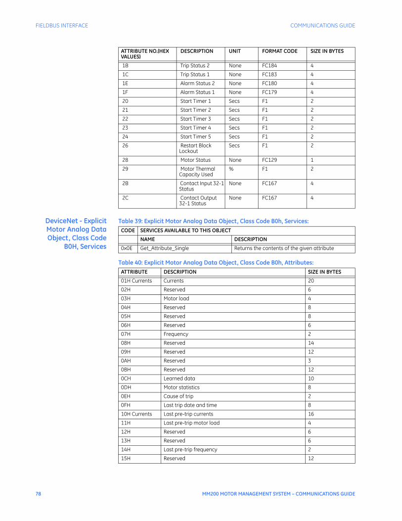
78 MM200 MOTOR MANAGEMENT SYSTEM – COMMUNICATIONS GUIDE
FIELDBUS INTERFACE COMMUNICATIONS GUIDE
DeviceNet - ExplicitMotor Analog DataObject, Class Code
B0H, Services
Table 39: Explicit Motor Analog Data Object, Class Code B0h, Services:
Table 40: Explicit Motor Analog Data Object, Class Code B0h, Attributes:
1B Trip Status 2 None FC184 4
1C Trip Status 1 None FC183 4
1E Alarm Status 2 None FC180 4
1F Alarm Status 1 None FC179 4
20 Start Timer 1 Secs F1 2
21 Start Timer 2 Secs F1 2
22 Start Timer 3 Secs F1 2
23 Start Timer 4 Secs F1 2
24 Start Timer 5 Secs F1 2
26 Restart Block Lockout
Secs F1 2
28 Motor Status None FC129 1
29 Motor Thermal Capacity Used
% F1 2
2B Contact Input 32-1 Status
None FC167 4
2C Contact Output 32-1 Status
None FC167 4
ATTRIBUTE NO.(HEX VALUES)
DESCRIPTION UNIT FORMAT CODE SIZE IN BYTES
CODE SERVICES AVAILABLE TO THIS OBJECT
NAME DESCRIPTION
0x0E Get_Attribute_Single Returns the contents of the given attribute
ATTRIBUTE DESCRIPTION SIZE IN BYTES
01H Currents Currents 20
02H Reserved 6
03H Motor load 4
04H Reserved 8
05H Reserved 8
06H Reserved 6
07H Frequency 2
08H Reserved 14
09H Reserved 12
0AH Reserved 3
0BH Reserved 12
0CH Learned data 10
0DH Motor statistics 8
0EH Cause of trip 2
0FH Last trip date and time 8
10H Currents Last pre-trip currents 16
11H Last pre-trip motor load 4
12H Reserved 6
13H Reserved 6
14H Last pre-trip frequency 2
15H Reserved 12
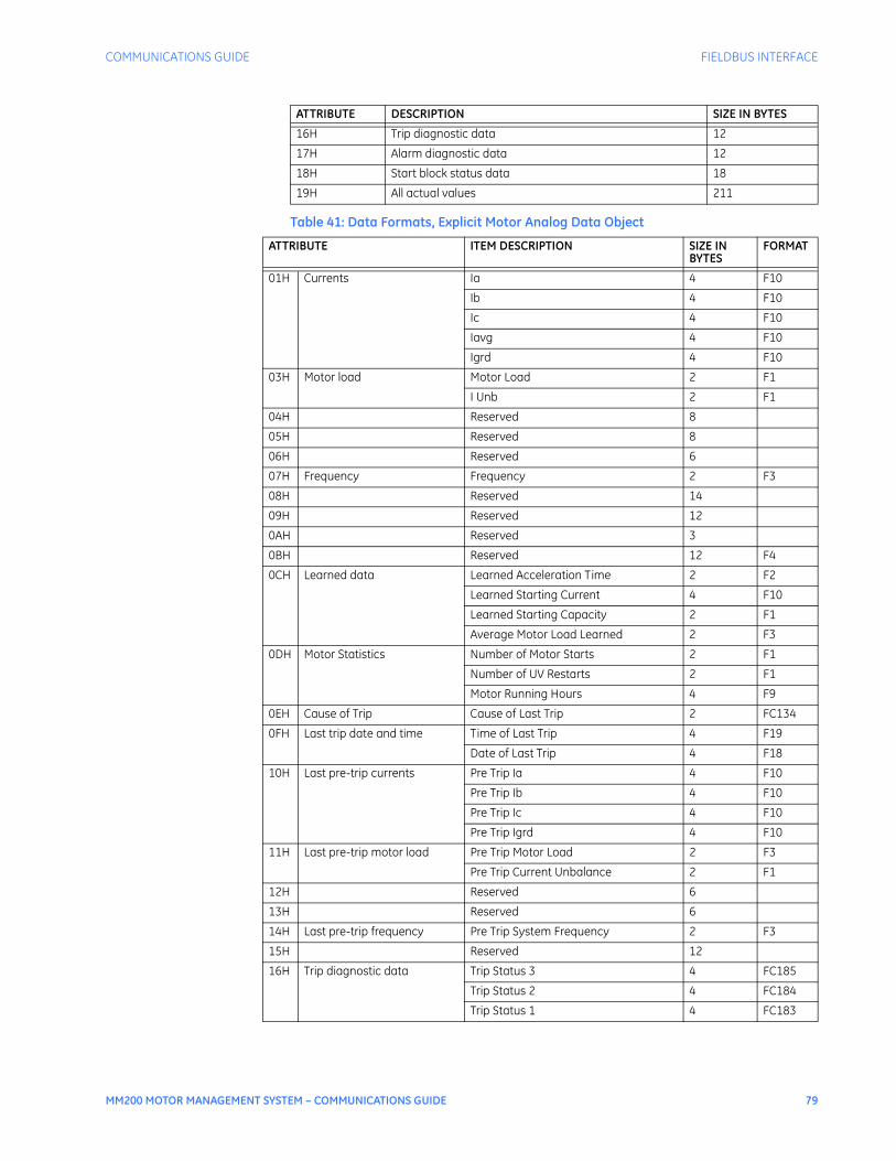
COMMUNICATIONS GUIDE FIELDBUS INTERFACE
MM200 MOTOR MANAGEMENT SYSTEM – COMMUNICATIONS GUIDE 79
Table 41: Data Formats, Explicit Motor Analog Data Object
16H Trip diagnostic data 12
17H Alarm diagnostic data 12
18H Start block status data 18
19H All actual values 211
ATTRIBUTE DESCRIPTION SIZE IN BYTES
ATTRIBUTE ITEM DESCRIPTION SIZE IN BYTES
FORMAT
01H Currents Ia 4 F10
Ib 4 F10
Ic 4 F10
Iavg 4 F10
Igrd 4 F10
03H Motor load Motor Load 2 F1
I Unb 2 F1
04H Reserved 8
05H Reserved 8
06H Reserved 6
07H Frequency Frequency 2 F3
08H Reserved 14
09H Reserved 12
0AH Reserved 3
0BH Reserved 12 F4
0CH Learned data Learned Acceleration Time 2 F2
Learned Starting Current 4 F10
Learned Starting Capacity 2 F1
Average Motor Load Learned 2 F3
0DH Motor Statistics Number of Motor Starts 2 F1
Number of UV Restarts 2 F1
Motor Running Hours 4 F9
0EH Cause of Trip Cause of Last Trip 2 FC134
0FH Last trip date and time Time of Last Trip 4 F19
Date of Last Trip 4 F18
10H Last pre-trip currents Pre Trip Ia 4 F10
Pre Trip Ib 4 F10
Pre Trip Ic 4 F10
Pre Trip Igrd 4 F10
11H Last pre-trip motor load Pre Trip Motor Load 2 F3
Pre Trip Current Unbalance 2 F1
12H Reserved 6
13H Reserved 6
14H Last pre-trip frequency Pre Trip System Frequency 2 F3
15H Reserved 12
16H Trip diagnostic data Trip Status 3 4 FC185
Trip Status 2 4 FC184
Trip Status 1 4 FC183

80 MM200 MOTOR MANAGEMENT SYSTEM – COMMUNICATIONS GUIDE
FIELDBUS INTERFACE COMMUNICATIONS GUIDE
DeviceNet - ExplicitMotor Object, Class
Code B1H
Table 42: Explicit Motor Control Object, Class Code B1h, Services:
Table 43: Explicit Motor Control Object, Class Code B1h, Attributes:
Table 44: Explicit Motor Control Data Format
17H Alarm diagnostic data Alarm Status 3 4 FC181
Alarm Status 2 4 FC180
Alarm Status 1 4 FC179
18H Start block status data Reserved 2
Start Timer 1 2 F1
Start Timer 2 2 F1
Start Timer 3 2 F1
Start Timer 4 2 F1
Start Timer 5 2 F1
Time Between Starts Lockout 2 F1B
Restart Block Lockout 2 F1
Starts/Hour Block 2 F1
19H All of the above items from attributes 01H-18H
ATTRIBUTE ITEM DESCRIPTION SIZE IN BYTES
FORMAT
CODE SERVICES AVAILABLE TO THIS OBJECT
NAME DESCRIPTION
0x10 Set_Attribute_Single Sets the contents of the given attribute
ATTRIBUTE ACCESS DESCRIPTION DATA TYPE VALUE
01H Set Control Command BYTE See below
VALUE DESCRIPTION
1 Reset
2 Lockout Reset
3 Stop
4 Start A
5 Start B
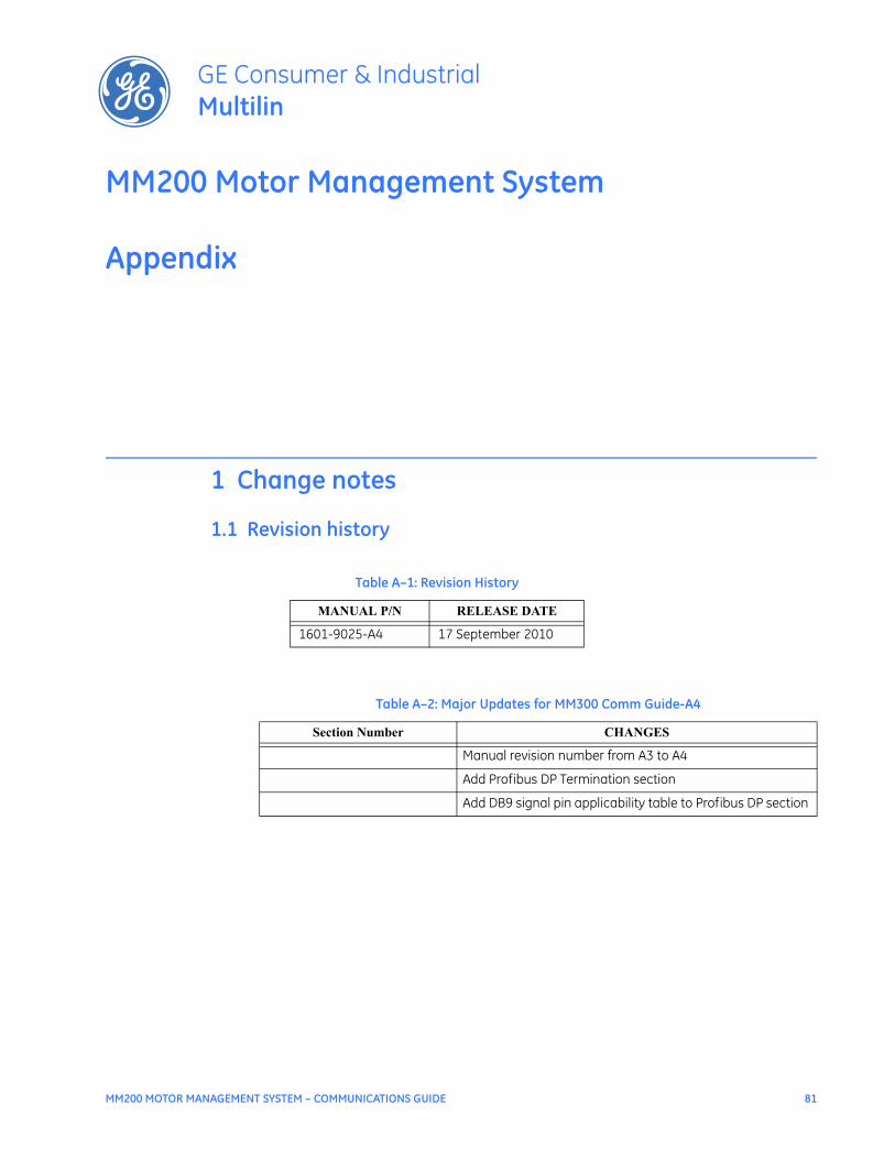
MM200 MOTOR MANAGEMENT SYSTEM – COMMUNICATIONS GUIDE 81
MM200 Motor Management System
Appendix
GE Consumer & IndustrialMultilin
Appendix
1 Change notes
1.1 Revision history
Table A–1: Revision History
MANUAL P/N RELEASE DATE
1601-9025-A4 17 September 2010
Table A–2: Major Updates for MM300 Comm Guide-A4
Section Number CHANGES
Manual revision number from A3 to A4
Add Profibus DP Termination section
Add DB9 signal pin applicability table to Profibus DP section
Table of contents

82 MM200 MOTOR MANAGEMENT SYSTEM – COMMUNICATIONS GUIDE
APPENDIX