Embed Size (px)
Citation preview

Common Agreement Document
of the
A380 Airport Compatibility Group
Version 2.1
December, 2002

2
Table of Content I. Introduction..............................................................................................................................3
I.1. AACG Terms of Reference..............................................................................................3 I.2. Purpose of the document ................................................................................................3 I.3. Primary conditions of application.....................................................................................4 I.4. Abbreviations....................................................................................................................4
II. Methodology Overview..........................................................................................................5 II.1. ICAO baseline identification .............................................................................................5 II.2. Hazard analysis ...............................................................................................................5 II.3. Risk assessment.............................................................................................................6 II.4. Conclusions .....................................................................................................................6
III. Airfield Items Review..............................................................................................................7 III.1. Introduction.......................................................................................................................7 III.2. Runways ..........................................................................................................................8 III.3. Taxiways ..........................................................................................................................9 III.4. Runway separations ......................................................................................................10 III.5. Taxiway and Taxilane separations.................................................................................11 III.6. Other items ....................................................................................................................12
IV. AACG Members Participation..............................................................................................13 ANNEX 1 Recommendation Letter from the 4 AACG Aviation Authorities ANNEX 2 National Supplements APPENDIX 1 Current Operations at today's Airports
Appendix 1 provides examples of Boeing 747 current operations at today’s aerodromes and extracts from databases (without analyses, modifications or extrapolations)
APPENDIX 2 Physical Characteristics of A380 Family Aircraft
Appendix 2 contains A380 basic physical characteristics (including wing span and outer main gear wheel span)
APPENDIX 3 Performance of A380 Family Aircraft Appendix 3 focuses on A380 specific performance and handling qualities in flight
APPENDIX 4 Studies, Analyses, Working Papers and Reports
Appendix 4 provides available documentation pertaining to aircraft operations
APPENDIX 5 Safety Analyses of Airfield Items
Appendix 5 develops the safety analyses that lead to the AACG conclusions

3
I. Introduction
I.1. AACG Terms of Reference The AACG is an informal group, consisting of a number of European Aviation Authorities, Airport and Industry representatives. It was formed to agree and promote a common position among the group members on the application of ICAO requirements, with respect to the A380 aircraft, for infrastructure and operations at existing major European airports that currently do not meet the requirements. Recognising that the ideal for A380 operations would be to provide a level of aerodrome infrastructure at least equal to the generic ICAO Requirements (contained within ICAO Annexes and ADM), the AACG should, in particular:
- Agree and promote that any deviations from these ICAO Requirements should be supported by appropriate aeronautical studies and relevant risk analyses;
- Report its work and findings to ICAO through the appropriate channels so that the
latter may use such data for the development of future provisions and enable the work of the group to be disseminated globally;
- Seek to promote the application of the agreed lesser requirements for the A380 aircraft within national regulatory frameworks; and
- Co-operate with other international organisations and working groups dealing with
NLA operations.
I.2. Purpose of the document The purpose of common agreement document is:
Ø to list the items of aerodrome infrastructure that may be affected by the introduction of the Airbus A380 aircraft;
Ø to examine the ICAO Recommended Practices relating to those items;
Ø to show the level of compliance of an aerodrome’s infrastructure with those
recommendations; and
Ø for those areas of non-compliance, to show appropriate mitigation, if required, proposed by the AACG to ensure the safe operation of the A380 aircraft at aerodromes currently unable to meet ICAO Code F Aerodrome Standards and Recommendations
Ø The AACG emphasises its position as an informal group proposing recommendations
to the relevant authorities. However, it is stressed that the authority to approve any deviation from ICAO Requirements shall rest solely with the state having jurisdiction over the aerodrome.
Ø No provision contained herein shall be construed so as to have a binding effect on any
such Authority with the respect to the approval of any such deviation.
4
I.3. Primary conditions of application a) The A380 requirements discussed and agreed by the AACG and listed in this document apply
only to the Airbus A380 Family as defined in Appendix 2. The wingspan of the A380 aircraft should be less than 80m and the outer main wheel span should be less than 14.4m.
b) The application of the different level of aerodrome infrastructure recommendations for A380
operations compared to code F is subject to:
• For runway width and runway separations items (§III.2 & §III.4), the A380 aircraft being certified to operate on a runway of Code E (minimum 45m) width for each type of operation (autoland, flight director and manual modes).
• For taxiway separations items (§III.5), where reduced margins exist compared to Code F
recommendations, proper guidance such as centre line lights or equivalent guidance (e.g. marshaller, etc.) to be provided for night, or low visibility operations. It may be permissible to operate with lower separation margins than agreed in this document if an aeronautical study taking into account local conditions indicates that such lower margins would not adversely affect the safety or significantly affect the regularity of operations of the A380.
c) Aerodromes intending to handle aircraft operations requiring Code F facilities as specified in
Annex 14 Volume 1 may, with approval of the appropriate authority, provide the inferior facilities specified in this document for the operation of A380 aircraft. However, facilities meeting Code F requirements should be provided in full on all relevant parts of the movement area where possible on new constructions or whenever major redevelopment of the movement area are undertaken. When planning such construction or redevelopment, it may be prudent to consider the requirements of future aircraft types needing facilities in excess of Code F.
I.4. Abbreviations [RP] A14 P3.8.3 = ICAO Recommended Practices Annex 14 Paragraph 3.8.3 [Std] = ICAO Standard ADM Pt2 = Aerodrome Design Manual part 2 Rwy = Runway Twy = Taxiway NLA = New Large Aircraft CRI = Certification Review Item FOD = Foreign Object Damage OPS = Operations ARFF = Aircraft Rescue and Fire Fighting OFZ = Obstacle Free Zone OLS = Obstacle Limitation Surface OCP = Obstacle Clearance Panel IIWG = International Industry Working Group JAR 25 = Joint Aviation Requirements for Large Aeroplane JAR AWO = Joint Aviation Requirements All Weather Operations OCA/H = Obstacle Clearance Altitude/Height RTO = Rejected Take-Off WP = Working Paper
5
II. Methodology Overview The methodology that the AACG proposed for establishing operational requirements and infrastructure needs might be applicable to any type of NLA. In this case, it has been developed and applied specifically to A380 aircraft (refer to Terms of Reference). The same simple philosophy (a safety analysis) in four steps has been used for each infrastructure item that may be affected by the introduction of the A380: runways, taxiways, runway separations, taxiway separations and other items (refer to Chapter III Airfield Items Review and Appendix 5 for some more detailed safety analyses). These four steps are as follows:
• ICAO baseline identification • Hazard analysis • Risk assessment • Conclusion
II.1. ICAO baseline identification ICAO baseline identification aims at reviewing ICAO SARPs and ICAO Justification Materials relating to an infrastructure item.
II.2. Hazard analysis Hazard analysis applied in this context is the identification of undesirable events and hazards linked to an infrastructure item using experience and operational judgement. Analysis has been made: • in terms of accident causal factors and critical events with a simple causal analysis, based
on experience and accident data base analyses. The accident information come from different databases: ICAO (ADREP), FAA (NTSB), aircraft manufacturers (Boeing, Airbus) and some airlines (see Appendix 1); and
• in terms of severity with a simple consequences analysis, based on experience and
accident data base analyses The following risk definitions are derived from JAR - FAR 25.1309 and are used in the infrastructure item safety analyses to define severity level of the different risks. Severity level Effect on aircraft and occupants CATASTROPHIC - Multiple fatalities
- Loss of the airplane HAZARDOUS - Large reduction in safety margins
- Physical distress or higher workload such that the flight crew cannot be relied upon to perform their tasks accurately or completely
- Serious or fatal injury to a small number of occupants MAJOR - Significant reduction in safety margins
- Significant increase in crew workload - Passenger injuries
MINOR - Slight reduction in safety margins - Slight increase in crew workload - Inconvenience to occupants
6
Moreover, JAR defines safety objectives based on the principle that there should be an inverse relationship between the severity of the effect of a failure and the probability of its occurrence (risk tolerability). JAR safety objectives are normally confined to aeroplane system failure analysis and not to a significant event in which all accident factors have been included. Therefore, particular accident factor rates cannot be simply linked with the global safety target level. A global risk assessment is most of the time problematic and not always relevant because the (statistically) most prominent contributor - human factors - is difficult to assess. These are the reasons why JAR safety objectives have not been considered entirely relevant at this stage. AACG members preferred, for most of the infrastructure items, simple qualitative analyses. Quantitative safety target level and risk models have only been used, at least for the moment, for specific risks well adapted to modelling.
II.3. Risk assessment Once each undesirable event is identified and analysed in terms of causes and consequences, the main remaining question is: “Are all identified risks under control?” Depending on the nature of the risks, three methods for risk assessment can be identified to respond to this question:
- Type A: For certain hazards, risk assessment strongly depends on specific aircraft performance and handling qualities. The safety level is achieved by the suitability between aircraft performance and handling qualities and infrastructure characteristics. Risk assessment, then, should be essentially based on the aircraft design and certification and on simulation results still to come.
- Type B:
For other hazards, the aircraft behaviour is not really linked with specific aircraft performance and handling qualities, and can be calculated from existing aircraft measurements. Risk assessment, then, should be based on statistics (e.g. deviations) for existing aircraft or accident analyses, and development of generic quantitative risk models can be well adapted.
- Type C:
In this case, a “risk assessment study” is not needed. In such a case, a simple geometric argument is sufficient to calculate infrastructure requirements without waiting for certification results or collecting deviation statistics for existing aircraft.
II.4. Conclusions Where possible, the result of a risk assessment should be the establishment of operational criteria to mitigate for the non-compliance of Code F facilities. These criteria should be regarded as minimum conditions with an aim to achieve similar operations at different airports. However, specific local conditions at an airport may prohibit the provision or application of the minimum conditions. In this case additional control measures should be implemented in order to provide an equivalent level of safety. In a few cases, the result of the risk assessment is dependent upon on going work of other bodies or working groups; therefore the outcome will be deferred until the results are known.
7
III. Airfield Items Review
III.1. Introduction The items of aerodrome infrastructure that may be affected by the introduction of the Airbus A380 aircraft have been identified as follows:
Ø Runways (§III.2.)
• Runway width • Width of runway shoulder
Ø Taxiways (§III.3.)
• Width of straight taxiway • Width of curved taxiway • Straight and curved taxiway shoulders
Ø Runway Separations (§III.4.)
• Runway to parallel taxiway separation • Obstacle Free Zone • Runway holding positions
Ø Taxiway & Taxilane Separations (§III.5.)
• Parallel taxiway separation (straight and curved) • Taxiway / Apron taxiway to object separation • Aircraft stand taxilane to object separation (including service road)
Ø Other Items (§III.6.)
• Clearance at the gate • Visual aid implications • Taxiway on bridges
Those infrastructure items are presented into tables (see below) and reviewed according to four points: Ø ICAO SARPs and ADM:
Standards and Recommended Practices contained in Annex 14 and material from the Aerodrome Design Manual issued by ICAO
Ø ICAO Justification Material: Information and formula used to elaborate the ICAO SARPs and ADM (applicable to code F aircraft as defined in Annex 14 Chapter I)
Ø AACG Agreement: Common position among AACG members on the application of ICAO Requirements with respect to the A380 aircraft, for infrastructure and operations at existing major European airports that currently do not meet the requirements
Ø AACG Justification Material: Major information used for the safety analyses found in Appendix 5
8
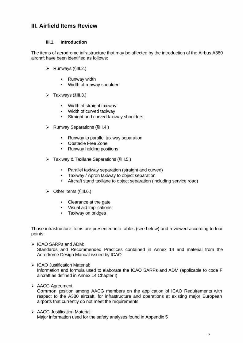
III.2. Runways
Item
Runway width
Width of Runway shoulder
ICAO SARPs
and ADM
The width of a rwy should be not less than 45m where the code letter is E, 60m where the code letter is F. [RP] A14 P3.1.9 Strength of rwys: A rwy should be capable of withstanding the traffic of aeroplanes the rwy is intended to serve. [RP] A14 P3.1.20
The rwy shoulders should extend symmetrically on each side of the rwy so that overall width of rwy and its shoulders is not less than 60m where the code letter is E and 75m where the code letter is F. [RP] A14 P3.2.3 Strength of rwy shoulders: A rwy shoulder should be prepared or constructed so as to be capable, in the event of an aeroplane running off the rwy, of supporting the aeroplane without inducing structural damage to the aeroplane and of supporting ground vehicles which may operate on the shoulder. [RP] A14 P3.2.5 A rwy shoulder should be prepared or constructed so as to minimise any hazard to an aeroplane running off the rwy. ADM Pt1 P5.2.2 In some cases, the bearing strength of the natural ground may be sufficient, without special preparation, to meet the requirements for shoulders. ADM Pt1 P5.2.3 Attention should also be paid when designing shoulders to prevent the ingestion of stones or other objects by turbine engines. ADM Pt1 P5.2.4 In case of special preparation, visual contrast between rwy and rwy shoulders may be needed. ADM Pt1 P5.2.5
ICAO
Justification Material
- Planning to accommodate future
aircraft developments ADM Pt1 P6 - Impossible to confirm existence of
the “1981 study” - NASA Ames study on 747 RTO not
conclusive
No specific justification material available on rwy shoulders to AACG
AACG
Agreement
A minimum central 45m of pavement of full load bearing strength shall be provided. *
- Compliance with the minimum 75m ICAO Code F runway + shoulders width - Minimum of 2x15m wide shoulders on existing 45m wide rwys: *
. At least 2x7.5m wide “inner” portion of rwy shoulders (definitions according to ICAO documents – see above) . Additional “outer” portion of rwy shoulders prepared for jet blast protection, engine ingestion protection, and for supporting ground vehicles.
- Minimum of 2x7.5m wide “outer” portion of rwy shoulders on existing 60m wide rwys - Depending on local conditions, decision on the composition and
thickness of rwy shoulders by each national authority and/or airport operator.
- If relevant to local conditions, snow removal and ice control as recommended by ICAO (Doc 9137-AN/898)
AACG Justification
Material
- A380 Certification on 45m wide rwy
- A380 Engines position - A380 Jet blast velocity & temperature contours at take-off thrust
* See §I.3.b)
9
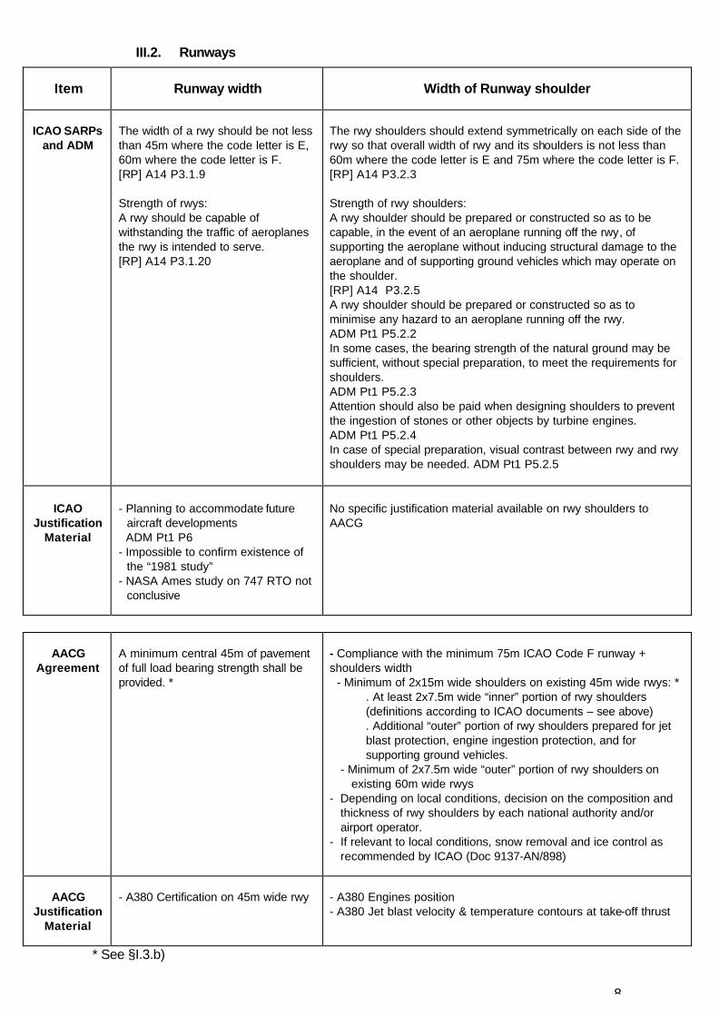
III.3. Taxiways
Item
Width of straight taxiway
Width of curved taxiway
Straight and curved taxiway
shoulders
ICAO SARPs and
ADM
Unless otherwise indicated, the requirements are applicable to all types of twys. A14 P3.8 Note Minimum clearance between outer main wheel and twy edge: 4.5m for both E and F. [RP] A14 P 3.8.3 Width of a straight portion: - 23m where code letter is E - 25m where code letter is F [RP] A14 P 3.8.4
Curves to ensure that when cockpit over twy centre-line, outer main wheel edge maintains 4.5m clearance from twy edge. [RP] A14 P3.8.5 ADM Pt2 p1.2.9 and ADM Pt2 p1.2.22 + tables 1-1 and 1-3
Overall width of twy + shoulders on straight portion: - 44m where code letter is E - 60m where code letter is F. [RP] A14 P3.9.1 The surface should be so prepared as to resist erosion and ingestion of the surface material by aeroplane engines. [RP] A14 P3.9.2 Intended to protect an a/c operating on the twy and to reduce the risk of damage to an a/c running off the twy. ADM Pt2 p1.6.1 ADM Pt2 p1.6.2+ table 1-1
ICAO
Justification Material
- Twy width = 2 x clearance
distance from wheel to pavement edge + max wheel track
Code E: 23m = 2x4.5m+14m Code F: 25m = 2x4.5m+16m ADM Pt2 p1.2.7+ table 1-1 - Origin of the 4.5m clearance
distance unknown to AACG
- Origin of the 4.5m clearance
distance unknown to AACG
- No specific justification material
available on taxiway shoulder width to AACG
AACG Agreement
- Minimum of 23m
- Wheel-to-edge minimum
clearance of 4.5m for code E and F aircraft
- On straight portions, Code F
compliant: 60m wide strip to be protected against shoulder erosion and engine ingestion (paved or natural surface)
- Depending on local conditions, decision on:
. the width for curved portions, . the composition and thickness for straight and curved portions by each national authority and/or airport operator
AACG
Justification Material
- Twy deviation statistics on
straight section, based on existing and on going studies
- A380 Landing gear wheel span and cockpit visibility
- No specific justification
needed (same rules as more critical aircraft such as A340-600 and 777-300ER)
- A380 Engine position - A380 Jet blast velocity &
temperature contours at break-away thrust
10
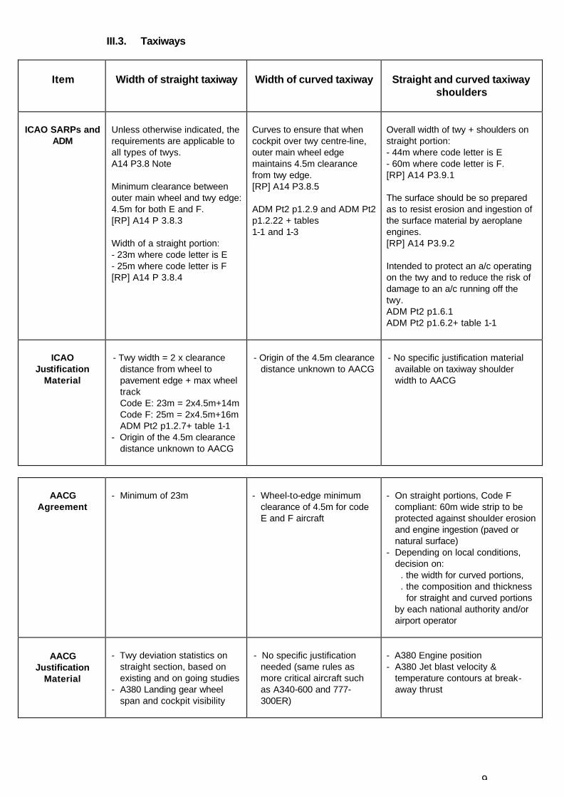
III.4. Runway separations
Item
RWY to parallel TWY separation
Obstacle Free Zone
Runway holding positions
ICAO
SARPS and ADM
190m for instrument rwy or 115m for non-instrument runway (may be reduced subject to aeronautical study). [RP] A 14 P3.8.7 + table 3-1 columns 5 & 9
OFZ half width = - 60m where code letter is E - 77.5m where code letter is F Then inner transitional surface slope 1:3 [Std] A14 P4.1.11 & 4.1.12 + 4.1.17 to 24, Table 4-1
Take-off rwy, non-instrument & non-precision approach minimum holding position distances - no change compared with code E (75m). Precision approaches all CATs: Minimum holding position distances increased to 107.5m for Code F (90m for Code E). [RP] A14 table 3-2 footnote ‘c’
A/C at precision approach holds – not to interfere with the operation of Nav. Aids [Std] A14 P3.11.6
ICAO
Justification Material
- Separation = ½ wing span + ½ strip
width: Code E:182.5m = ½x65m+½x300m Code F:190m = ½x80m+½x300m for instrument rwy ADM Pt2 p1.2.19+ table 1-5 - Origin of the 300m rwy strip width
unknown to AACG
- No justification material in ICAO official publications
- Justifications in OCP meetings materials:
155m (Code F) = 120m (Code E) + 20m (wingspan increase from initial Code E 60m to Code F 80m) + 15m (rwy width increase from code E 45m to code F 60m)
- 107.5m based on Code F OFZ
definition and on an aircraft with 24m tail height, 62.2m distance nose-highest tail part, 10m nose height, 45° or more holding
AACG
Agreement
Collision risk: - For non-instrument runways, ICAO
SARPs to be followed (115m for code F).
- For instrument runways, no generic operational agreement. *
190m regarded as conservative ILS effects: - Need for specific runway studies to
evaluate ILS interference risks in all cases.
Pending on-going studies (OCP), possibility of reduced Code F OFZ width (155m) for A380 operations on 45m wide runways. *
Collision risk: - For take off, non-instrument &
non-precision approach runways, minimum ICAO SARPs to be followed (75m). In some complex airport layouts (parallel runways, intermediate taxiways used to cross runways,...), rwy holding positions may be specifically studied when rwys are used by A380.
- Possibility of reduced Code F minimum holding point distances for collision risk reasons (OFZ). *
ILS effects: - Need for specific runway
studies to evaluate ILS interference risks in all cases
AACG
Justification Material
Collision risk: - Common Accident/Incident
database (ICAO, NTSB, Airbus, Boeing, Airlines, Press)
- NCAA/AEA report for code F rwy strip width: “90m+aircraft half span” (only relevant to collision risk, not to ILS interference)
ILS effects: - ADP study - Park Air Systems study (based on an A380 vertical tail in metal)
- ICAO OCP - OFZ study,
preliminary 747 results in autoland mode
- ADP investigation on OFZ for A380 operations on 45m wide rwy
- St Petersburg formula for A380 ops on 45m wide rwys
- NCAA/AEA report
Collision risk: - Investigation by ADP on OFZ
for A380 ops on 45m wide rwy ILS effects: - ADP study - Park Air Systems study (based
on an A380 vertical tail in metal)
* See §I.3.b)
11
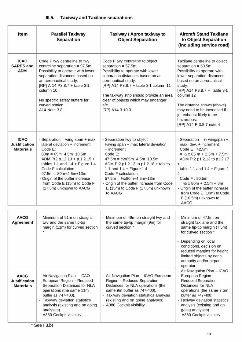
III.5. Taxiway and Taxilane separations
Item
Parallel Taxiway
Separation
Taxiway / Apron taxiway to
Object Separation
Aircraft Stand Taxilane to Object Separation
(including service road)
ICAO
SARPS and ADM
Code F twy centreline to twy centreline separation = 97.5m. Possibility to operate with lower separation distances based on an aeronautical study. [RP] A 14 P3.8.7 + table 3-1 column 10 No specific safety buffers for curved portion. A14 Note 3.8
Code F twy centreline to object separation = 57.5m. Possibility to operate with lower separation distances based on an aeronautical study. [RP] A14 P3.8.7 + table 3-1 column 11 The taxiway strip should provide an area clear of objects which may endanger a/c [RP] A14 3.10.3
Taxilane centreline to object separation = 50.5m. Possibility to operate with lower separation distances based on an aeronautical study. [RP] A14 P3.8.7 + table 3-1 column 12 The distance shown (above) may need to be increased if jet exhaust likely to be hazardous. [RP] A14 P 3.8.7 note 4
ICAO
Justification Materials
- Separation = wing span + max lateral deviation + increment Code E: 80m = 65m+4.5m+10.5m ADM Pt2 p1.2.13 + p.1.2.15 + tables 1-1 and 1-4 + Figure 1-4 Code F calculation: 97.5m = 80m+4.5m+13m - Origin of the buffer increase
from Code E (15m) to Code F (17.5m) unknown to AACG
- Separation twy to object = ½wing span + max lateral deviation + increment Code E: 47.5m = ½x65m+4.5m+10.5m ADM Pt2 p1.2.13 to p1.2.18 + tables 1-1 and 1-4 + Figure 1-4 Code F calculation: 57.5m = ½x80m+4.5m+13m - Origin of the buffer increase from Code
E (15m) to Code F (17.5m) unknown to AACG
- Separation = ½ wingspan + max. dev. + increment Code E : 42.5m = ½ x 65 m + 2.5m + 7.5m ADM Pt2 p1.2.13 to p1.2.17 + table 1-1 and 1-4 + Figure 1-4 Code F : 50.5m = ½ x 80m + 2.5m + 8m - Origin of the buffer increase
from Code E (10m) to Code F (10.5m) unknown to AACG
AACG
Agreement
- Minimum of 91m on straight
twy and the same tip-tip margin (11m) for curved section *
- Minimum of 49m on straight twy and
the same tip-tip margin (9m) for curved section *
- Minimum of 47,5m on
straight taxilane and the same tip-tip margin (7.5m) for curved section *
- Depending on local
conditions, decision on reduced margins for height limited objects by each authority and/or airport operator.
AACG
Justification Materials
- Air Navigation Plan – ICAO
European Region – Reduced Separation Distances for NLA operations (the same 11m buffer as 747-400).
- Taxiway deviation statistics analysis (existing and on going analyses)
- A380 Cockpit visibility
- Air Navigation Plan – ICAO European
Region – Reduced Separation Distances for NLA operations (the same 9m buffer as 747-400).
- Taxiway deviation statistics analysis (existing and on going analyses)
- A380 Cockpit visibility
- Air Navigation Plan – ICAO European Region – Reduced Separation Distances for NLA operations (the same 7.5m buffer as 747-400).
- Taxiway deviation statistics analysis (existing and on going analyses)
- A380 Cockpit visibility
* See I.3.b)
12
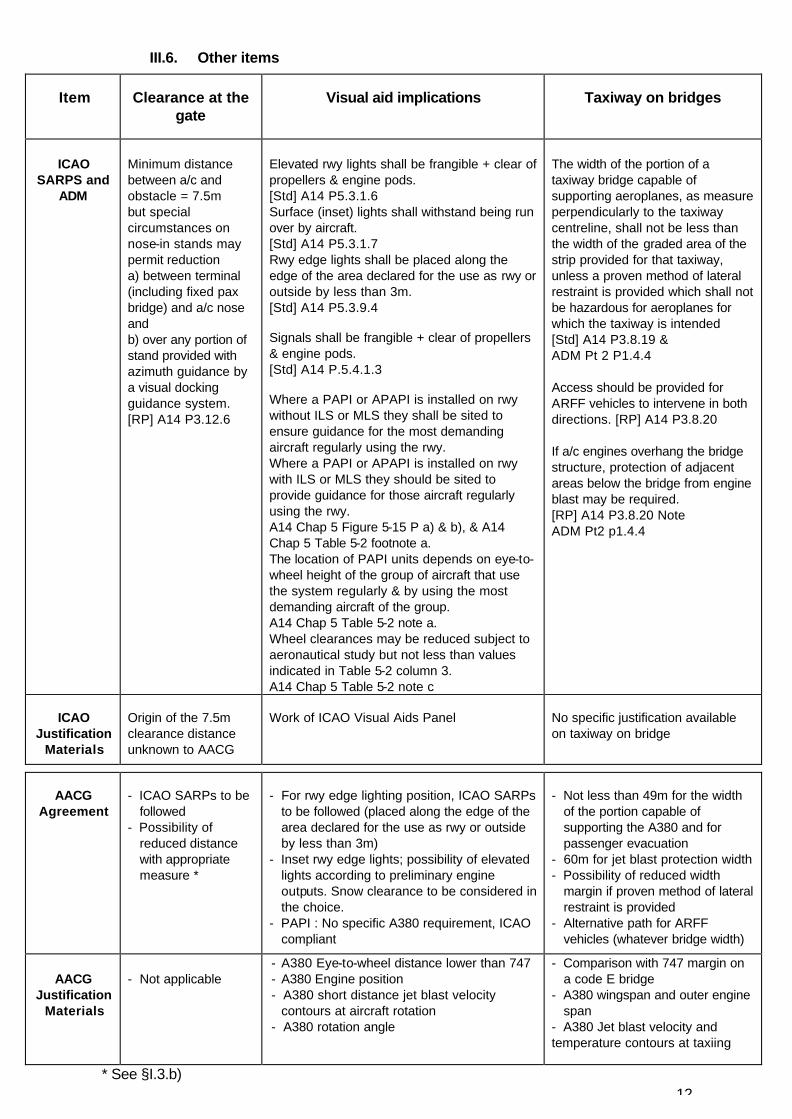
III.6. Other items
Item
Clearance at the gate
Visual aid implications
Taxiway on bridges
ICAO
SARPS and ADM
Minimum distance between a/c and obstacle = 7.5m but special circumstances on nose-in stands may permit reduction a) between terminal (including fixed pax bridge) and a/c nose and b) over any portion of stand provided with azimuth guidance by a visual docking guidance system. [RP] A14 P3.12.6
Elevated rwy lights shall be frangible + clear of propellers & engine pods. [Std] A14 P5.3.1.6 Surface (inset) lights shall withstand being run over by aircraft. [Std] A14 P5.3.1.7 Rwy edge lights shall be placed along the edge of the area declared for the use as rwy or outside by less than 3m. [Std] A14 P5.3.9.4 Signals shall be frangible + clear of propellers & engine pods. [Std] A14 P.5.4.1.3 Where a PAPI or APAPI is installed on rwy without ILS or MLS they shall be sited to ensure guidance for the most demanding aircraft regularly using the rwy. Where a PAPI or APAPI is installed on rwy with ILS or MLS they should be sited to provide guidance for those aircraft regularly using the rwy. A14 Chap 5 Figure 5-15 P a) & b), & A14 Chap 5 Table 5-2 footnote a. The location of PAPI units depends on eye-to-wheel height of the group of aircraft that use the system regularly & by using the most demanding aircraft of the group. A14 Chap 5 Table 5-2 note a. Wheel clearances may be reduced subject to aeronautical study but not less than values indicated in Table 5-2 column 3. A14 Chap 5 Table 5-2 note c
The width of the portion of a taxiway bridge capable of supporting aeroplanes, as measure perpendicularly to the taxiway centreline, shall not be less than the width of the graded area of the strip provided for that taxiway, unless a proven method of lateral restraint is provided which shall not be hazardous for aeroplanes for which the taxiway is intended [Std] A14 P3.8.19 & ADM Pt 2 P1.4.4 Access should be provided for ARFF vehicles to intervene in both directions. [RP] A14 P3.8.20 If a/c engines overhang the bridge structure, protection of adjacent areas below the bridge from engine blast may be required. [RP] A14 P3.8.20 Note ADM Pt2 p1.4.4
ICAO
Justification Materials
Origin of the 7.5m clearance distance unknown to AACG
Work of ICAO Visual Aids Panel
No specific justification available on taxiway on bridge
AACG
Agreement
- ICAO SARPs to be
followed - Possibility of
reduced distance with appropriate measure *
- For rwy edge lighting position, ICAO SARPs
to be followed (placed along the edge of the area declared for the use as rwy or outside by less than 3m)
- Inset rwy edge lights; possibility of elevated lights according to preliminary engine outputs. Snow clearance to be considered in the choice.
- PAPI : No specific A380 requirement, ICAO compliant
- Not less than 49m for the width
of the portion capable of supporting the A380 and for passenger evacuation
- 60m for jet blast protection width - Possibility of reduced width
margin if proven method of lateral restraint is provided
- Alternative path for ARFF vehicles (whatever bridge width)
AACG
Justification Materials
- Not applicable
- A380 Eye-to-wheel distance lower than 747 - A380 Engine position - A380 short distance jet blast velocity
contours at aircraft rotation - A380 rotation angle
- Comparison with 747 margin on a code E bridge
- A380 wingspan and outer engine span
- A380 Jet blast velocity and temperature contours at taxiing
* See §I.3.b)

13
IV. AACG Members Participation This document reflects the common position of AACG members, listed above, namely European Aviation Authorities, Airport Authorities and Operators, ACI, Airbus and IATA, on the application of ICAO requirements with respect to the A380 aircraft. List of AACG Participants COMPANY NAME POSITION
Airports and their Authorities France
ADP Gérard Batistella Studies and Development - Air traffic Operations ADP Philippe Laborie Chief Engineer Master planning DGAC Kim Nguyen Deputy Director, Air Base Department – SBA
DGAC Pierre Théry Air Base Department - Infrastructure Office – SBA
DGAC Brigitte Verdier Regulation Office - Aerodrome Division – DNA
DGAC Aude Malige Airports and Airforce Bases Engineering – Airport Planning – STBA
Germany FRAPORT Ibrahim Zantout Head Airport Infrastructure
FRAPORT Oliver Kohlbacher Infrastructure Project Manager, Airside Infrastructure – Traffic & Retail
FRAPORT Ralf Struck Infrastructure Project Manager, Airside Infrastructure – Traffic & Retail
ADV Udo Wolffram Director of Planning (and Chairman of IIWG New Large Aircraft Study Group)
HMWVL Egon Grosslein Head of Section – CAA Aerodromes, Technical Affairs, Airport Operations, Security
BMVBW Klaus Albrecht Federal Regulatory Authority Netherlands
AMS Dick Meerman Business Unit Airlines AMS Rob ten Hove Senior advisor airside infrastructure
CAA Netherlands Sietse Jager Division Aerodromes and Airspace (and Chairman of ADSG Project Team 4)
United Kingdom AOA/BAA Andrew Badham Senior Operations Manager MAN Debbie Riley Airfield Policy and Planning Manager
CAA UK Geoff Caton Head Aerodrome Standards Department – Safety Regulation Group
CAA UK Paul Fleming Team Manager, Policy, Standardization & Development Section, Aerodrome Standards Department
International bodies & Industry ACI (Chairman) David Gamper Director Facilitation & Technical / Safety AIRBUS (Secretary and Technical Advisor) Jean-Paul Genottin Infrastructure Manager - A380 Programme
AIRBUS (Secretary and Technical Advisor) Christian Siames Infrastructure Manager - A380 Programme
AIRBUS (Secretary and Technical Advisor) Laurent Evain Infrastructure Engineer - A380 Programme
IATA (Advisor) Ton Van Der Veldt Assistant Director - Operations & Infrastructure
14
ANNEX 1
Recommendation Letter from the 4 AACG Aviation Authorities
• FRANCE • GERMANY
• NETHERLANDS
• UNITED KINGDOM


15
16

ANNEX I TO THE COMMON AGREEMENT DOCUMENT
OF THE A380 AIRPORT COMPATIBILITY GROUP
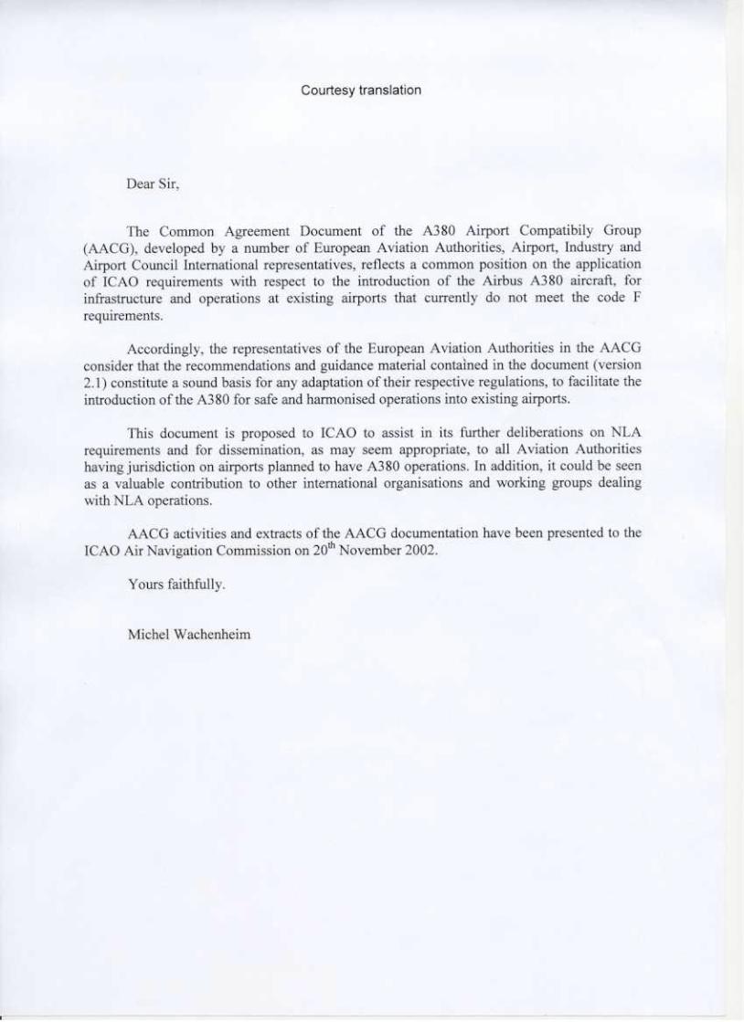
Recommendation Letter
The Common Agreement Document of the A380 Airport Compatibility Group (AACG), developed by a number of European Aviation Authorities, Airport, Industry and Airport Council International representatives, reflects a common position on the application of ICAO requirements with respect to the introduction of the Airbus A380 aircraft, for infrastructure and operations at existing airports that currently do not meet the Code F requirements.
Accordingly, the representatives of the European Aviation Authorities in the AACG consider that the recommendations and guidance materials contained in the document (version 2.1) constitute a sound basis for any adaption of their respective regulations, to facilitate the introduction of the A380 for safe and harmonised operations into existing airports.
This document is proposed to ICAO to assist in its further deliberations on NLA requirements and for dissemination, as may seem appropriate, to all Aviation Authorities having jurisdiction on airports planned to have A380 operations. In addition, it could be seen as a valuable contribution to other international organisations and working groups dealing with NLA operations.
AACG activities and extracts of the AACG documentation have been presented to the ICAO Air Navigation Commission on 20 November 2002.
The policy stated in the Common Agreement Document of the AACG is regarded by the United Kingdom as interim policy with respect to the introduction of the Airbus 380 aircraft for infrastructure and operations at existing airports that currently do not meet the Code F requirements. For the design of new airports or the extension of existing airports intended for the operation of the A380 aircraft, Annex 14 Code 4 F criteria are applicable.
G Caton Head of Aerodrome Standards Department Safety Regulation Group United Kingdom Civil Aviation Authority

17
ANNEX 2
National Supplements France For taxiway width item, currently under discussion Germany No National Supplements Netherlands In the Netherlands the application of a deviation of 2.5 m for code F aircraft instead of 4.5 m is allowed after an approval by the appropriate authority. United Kingdom No National Supplements
18
APPENDIX 1
Current Operations in Today's Airports
Appendix 1 provides examples of Boeing 747 current operations at today’s aerodromes and extracts from
databases (without analyses, modifications or extrapolations)
Part A: Minimum infrastructure items observed for Boeing 747 operations in today’s airports that do not meet Code E / Group V SARPs
Part B: Common Accident/Incident lateral runway excursions database
(Narrow Bodies and Wide Bodies) Part C: Common Accident/Incident lateral taxiway excursions database (Narrow Bodies and Wide Bodies) Part D: Preliminary data of the on-going taxiway deviation study at CDG
19
APPENDIX 2
Physical Characteristics of A380 Family Aircraft
Appendix 2 contains A380 basic physical characteristics
including wing span and outer main gear wheel span
Part A: A380-800 / 747-400 Geometric Comparisons Part B: Runway Situation Part C: Taxiway Situation Part D: Bridge Situation Part E: A380 Ground Visibility Part F: ARFF Vehicles and Evacuation slides Part G: Extract of “ A380 Characteristics for Airport Planning “
(Scope, aeroplane description, ground manoeuvring and operating conditions)
Part H: A380 short distance jet blast contours Part I: Jet blast contours of other aircraft (747-400, 777-200LR/300ER, A340-
500/600)
20
APPENDIX 3
Performance of A380 Family Aircraft
Appendix 3 focuses on A380 specific performance and handling qualities in flight
Part A: Certification objectives for operations from 45m wide runways Part B: A380 Flight Handling Qualities
Part C: Autoland System Design Part D: Landing incidence/attitude and cockpit visibility Part E: Position of A380 Glide Path Antenna
21
APPENDIX 4
Studies, Analyses, Working Papers and Reports
Appendix 4 provides available documentation pertaining to
aircraft operations
Documentation on taxiways Part A: “Air Navigation Plan – ICAO European Region – Reduced Separation Distances Part B: “Taxiway Deviation Study” 1987. BAA report on taxiway deviations at LHR (included
in ICAO Annex 14).
Part C: “Statistical Analysis of Aircraft Deviations from Taxiway Centreline” 1995. Boeing Computer Services. Boeing Analysis of Schiphol Measured Deviations.
Part D: “Reduced Separation Distances for Code F aircraft at Amsterdam Airport Schiphol” By Rob ten Hove of Amsterdam Airport Schiphol, Oct 1, 2001.
Part E: “Aircraft Deviation Analysis” By Ibrahim Zantout, FRAPORT, June 5, 2002.
Part F: “Update on the Taxiway Deviation Studies at JFK and ANC”, By Dan Cohen-Nir, ACI-NA – presented at NLAFG – July 2002 Documentation on runways Part G: “Final Report on the Risk Analysis in Support of Aerodrome Design Rules”. 2001.
Report produced by AEA Technology for the Norwegian Civil Aviation Authority.
Part H: “Common Lateral Runway Accident/Incident Database Analyses – Period 1980-2000” by Airbus, 2002
Part I: “Fatal Accident Analysis” – Extract of the Statistical Aviation Safety Summary by the National Aerospace Laboratory (NLR) for CAA NTH and analysis of fatal accident of the common Accident/Incident database by Airbus
Part J: “Findings of Monte-Carlo Simulation Autoland Study of the Balked Landing in Support of the NLA OFZ Study” Presented by Lynn Boniface at the OCP 12.
Part K: OCP 13 W/P PANS OPS implementation issues/New Larger Aircraft on OFZ - October 2002.
Part L: “Investigation on the OFZ for A380 Operations on 45m wide runways” ADP – June 2002
Part M: “Sensitive Areas for NORMAC ILS Localizer due to effect of Airbus 380” By Park Air Systems – April 2002
22
APPENDIX 5
Safety Analyses of Airfield Items
Appendix 5 develops the safety analyses that lead to the AACG conclusions
Part A: Runways Part B: Taxiways Part C: Runway separations Part D: Taxiway separations Part E: Other items


![SinGAPORE AIRLInES A380* 456 ! A380] 333 A380 E 1531 …singapore airlines a380* 456 ! a380] 333 a380 e 1531 a330 [1-2-1 singapore airlines](https://img.pdfslide.us/doc/110x75/5f1f304da44bc1238e46c157/singapore-airlines-a380-456-a380-333-a380-e-1531-singapore-airlines-a380-456.jpg)