Embed Size (px)
Citation preview

C o m b u s t i o n m a d e e a s y
Instruction Manual
C20 Combustion Set-Up
Meter
www.actoolsupply.com
www.actoolsupply.com

TABLE OF CONTENTS
Getting Started Safety ................................................................................................... 1C20 Functions ..................................................................................... 1Analyzer Connections ....................................................................... 1Operations ........................................................................................... 1Typical Uses ....................................................................................... 1Overview.............................................................................................. 2MaintenanceGeneral Maintenance ....................................................................... 3Water Trap .......................................................................................... 3Changing Particle Filter .................................................................... 3Battery Replacement ........................................................................ 4Electromagnetic Compatibility ......................................................... 4Combustion InformationWhy Test With The C20 .................................................................... 5Acceptable Results ........................................................................... 6Meter Problem Solving ..................................................................... 7GlossarySelector and Display Parameters ................................................... 8Meter Specifications ......................................................................... 9Warranty............................................................................................ 10
www.actoolsupply.com
www.actoolsupply.com

Safety NoteS Before using this meter, read all safety information carefully. In this manual the word “WARNING” is used to indicate conditions or actions that may pose physical hazards to the user. The word “CAUTION” is used to indicate conditions or actions that may damage this instrument.
WARNING! This analyzer extracts combustion gases that may be toxic in relatively low concentrations. These gases are exhausted from the back of the instrument. This instrument must only be used in well-ventilated locations.It must only be used by trained and competent persons after due consideration of all the potential hazards.
C20 fuNCtioNS •CarbonMonoxide(CO)Measuredinpartpermillion(ppm) •CarbonDioxide(CO2)Measuredinpercentagevolume(%) •COMAX-MaximumCOmeasured.
aNalyzer CoNNeCtioNS WARNING!
Turning the pump off while the probe is in the flue will leave toxic gases inside the analyzer. Once data has been read, it is advisable to purge the unit with fresh air as soon as possible. To do this, with the probe removed from the flue, turn ON the pump. Always allow the readingstoreturntozero(00forCO)priortoshuttingtheunitoff.
WARNING! The probe will be hot from flue gases. Remove the probe from the flue andallowittocoolnaturally.Donotimmersetheprobeinwater,asthis will be drawn into the analyzer and damage the pump and sen-sors. Once the probe is removed from the flue and the readings have returned to ambient levels rotate the selector to “OFF”and switch off theanalyzer.Theinstrumentwillcountdownfrom30toswitchoff.
C20 operatioNS TheC20Combustionset-upmeterissuitableforusewithallcommondomesticfuelsincludingnaturalgas,propane, butane and light oil.
NOTE:Alwaysbeginoperationinanareawithfreshair,freefromanyCOorCO2.
• PowertheC20onbyrotatingtheselectordialtoanyposition • AllowtheC20tocompletecountdown • Rotateselectordialtodesiredparameterandbegintesting
WhennotmeasuringCOorCO2rotateselectorto“STANDBY”toextendbatterylife.
C20 CombuStioN Set-up meter typiCal uSeS • Measureandverifymanufactureset-upvaluesforCO2andCOarewithinspecifiedrange. • Checkforfluegasspillagearoundcapturehoods. • MeasurebackgroundandambientCOlevels.
OWNERS MANUAL & MAINTENANCE
1
www.actoolsupply.com
www.actoolsupply.com
2
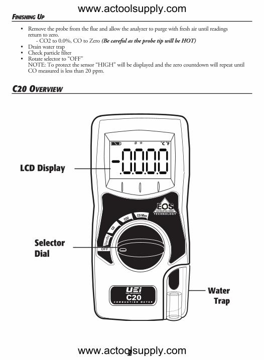
fiNiShiNg up • Remove the probe from the flue and allow the analyzer to purge with fresh air until readings return to zero. -CO2to0.0%,COtoZero(Be careful as the probe tip will be HOT) • Drainwatertrap • Checkparticlefilter • Rotateselectorto“OFF” NOTE: To protect the sensor “HIGH” will be displayed and the zero countdown will repeat until COmeasuredislessthan20ppm.
C20 overview
OFF
Standby
CO
CO2CO Max
˚C ˚F
0000LCD Display
SelectorDial
Water Trap
www.actoolsupply.com
www.actoolsupply.com

geNeral maiNteNaNCe •Checkcalibrationofyourinstrumentannuallytoensureitmeetsoriginalperformancespecifications •Keepyourinstrumentdry.Ifitgetswet,wipedryimmediately.Liquidscandegradeelectroniccircuits •Wheneverpractical,keeptheinstrumentawayfromdustanddirtthatcancauseprematurewear •Althoughyourinstrumentisbuilttowithstandtherigorsofdailyuse,itcanbedamagedbysevere impacts. Use reasonable caution when using and storing the meter.
periodiC ServiCe WARNING! Repairandserviceofthisinstrumentistobeperformedbyqualifiedpersonnelonly.Improperrepairor service could result in physical degradation of the instrument. This could alter the protection from per-sonal injurythismeterprovidestotheoperator.Performonlythosemaintenancetasksthatyouarequalifiedtodo.
aNNual re-CalibratioN While the sensors have an expected life of more than five years in normal use it is recommended that the analyzerisre-calibratedannually.Thisissothatlong-termdriftcanbeeliminated.Localregulationsmayrequiremorefrequentre-calibrationandusersshouldcheckwithappropriateauthoritiestoensure compliance with relevant guidelines.
CleaNiNg Periodicallycleanyourinstrumentscaseusingadampcloth.DONOTuseabrasive,flammableliquids, cleaning solvents, or strong detergents as they may damage the finish, impair safety, or affect the reliability of the structural components.
emptyiNg & CleaNiNg the iN-liNe water trap The in-line water trap should be checked and emptied on a regular basis. Water vapor will condense in the probe line, which may cause the water trap to fill suddenly if the probe is moved. Care should be taken at all times. Carefully un-screw the plug from the bottom of the water-traphousing.Disposeofthecondensateinasuitabledrain, care must be taken as it could be acidic. If conden-sate spills onto the skin or clothing, clean off immediately using fresh water, seek medical advice if problems occur. Ensure plug is replaced before performing combustion tests.Note:CO2readingwillbelowiftheWaterTrapPlugisnotinplace.
ChaNgiNg the partiCle filter
This is a very important part of the analyzer and should be changed regularly. It prevents dust and dirt particlesfromenteringthepumpandsensorsthatwillcausedamage.ThefilterMUSTbechangedwhenitappears discolored on the inner surface. Remove water-trap assembly from the analyzer as shown above. Remove the filter and plastic holder from the housing. Discardthefilterelementbutkeeptheholdertofittothenewfilter. Clean the inside of the filter housing with a suitable soft cloth. Fit the holder onto the new filter element and then insert into the housing. Refit the housing onto the analyzer.
Hook slidesout of dock
Slide outward
Unscrew plug to drain
3
Insert a new filter
www.actoolsupply.com
www.actoolsupply.com

4
batterieS replaCemeNt
This meter has been designed for use with alkaline batteries. No other types of batteries are recommended. The analyzer is supplied with 4 “AA” size alkaline batteries. These should be installed into the instrument as shown in the diagram to the right and indicated on the back of the unit.
CAUTION! Take great care when installing the batteries to observe correct polarity. Always check the meter for operation immediately after installing new batteries.
eleCtromagNetiC Compatibility (emC) This product has been tested for compliance with the following generic standards: EN50081-1,EN50082-1andiscertifiedtobe compliant.
TheEuropeanCouncilDirective89/336/EECrequiresthatelectronicequipmentdoesnotgenerateelec-tromagneticdisturbancesthatexceeddefinedlevelsandhasanadequatelevelofimmunitytoenableittobeoperated as intended.
Sincetherearemanyelectricalproductsinusethatpre-datethisDirectiveandmayemitelectromagneticradiationinexcessofthestandardsdefinedintheDirectivetheremaybeoccasionswhereitwouldbeappro-priate to check the analyzer prior to use. The following procedure should be adopted.
•Gothroughthenormalstartupsequenceinthelocationwheretheequipmentistobeused •Switchonalllocalizedelectricalequipmentthatmightbecapableofcausinginterference •Checkthatallreadingsareasexpected(alevelofdisturbanceinthereadingsisacceptable) •Ifnot,adjustthepositionoftheinstrumenttominimizeinterferenceorswitchoff, ifpossible,theoffendingequipmentforthedurationofthetest
Atthetimeofwritingthismanual(August2011),UEiisnotawareofanyfieldbasedsituationwheresuch interferencehaseveroccurredandthisadviceisonlygiventosatisfytherequirementsoftheDirective.
Note: Follow battery directions on back of housing
Battery Compartment
Cover
Back ofInstrument
www.actoolsupply.com
www.actoolsupply.com

verify proper operatioN of CombuStioN equipmeNt
• Toverifythatequipmentisoperatingasthemanufacturerdesignedittowork. ThisincludesinstallationtestsforCO2andCO. - A properly tuned combustion appliance will perform better, and reduce the likelihood of call-backs for no-heat. • Toverifythatthemaintenanceworkperformedhascorrectedtheproblem. • Todetectanydefectsearly–possiblyatinstallation. -Higherefficiencyequipmentisrunningatpeakonlywhenproperlyadjusted.Asthecomplexity of a system increases, so does the importance of proper adjustment of the combustion process. • Improperlyadjustedequipmentnotonlyfailstomeetexpectedperformancebutcouldleadtofuture failures. • Tocheckthattheequipmentissuppliedwithenoughcombustionair,make-upairandhasproper venting to exhaust the combustion by-products. • Toestablishabase-lineofdesiredperformance- -Bytrackingtheperformanceovertimeyouareabletoseechangesbeforetheyleadtoequipment failure.
verify Safe operatioN of CombuStioN equipmeNt
• Equipmentthatisnotproperlyadjusted,orthathasinsufficientdrafttoventcombustiongasescould producecarbonmonoxideindeadlyquantities.TheUEiC20canbeusedtotestbothfluegasand ambient CO. • Whencustomerscomplainaboutfumesitisusuallyanindicationofimproperoperation.COisa colorless, odorless gas so the fumes are not the CO, but an indication that a problem may exist.
improve your produCtivity & profit • TheUEiC20 combustionset-upmetergivesaquick,continuousreadoutofthecombustionprocess. Readings change in real-time as adjustments are made to help zero in on the proper setting. Compare this to spot tests or other methods, and you will see your productivity rise. • Propertestingwillhelpyouprovidetheproperserviceorequipmentreplacement recommendations, andhavethedatatosupportthis.Saleswillincreasebecauseyouarenolongerguessing,andthe work provided is proper for the needs of the customer. • Customersonaservicecontractwillbeprovidedexcellentservice,andyouwillquicklydiagnose failuresandhelpkeeptheequipmentupfortheseason. improve CuStomer perCeptioN of your ServiCeS
• Provideyourcustomersresultsoftheperformanceoftheirequipment • Reduceyourcustomersenergyexpensebyproperlyadjustingandmaintainingtheirequipment • Increaseyourconfidenceintheworkperformedandremember
if you doN’t teSt, you doN’t KNow
WHY TEST WITH THE C20
5
www.actoolsupply.com
www.actoolsupply.com
6
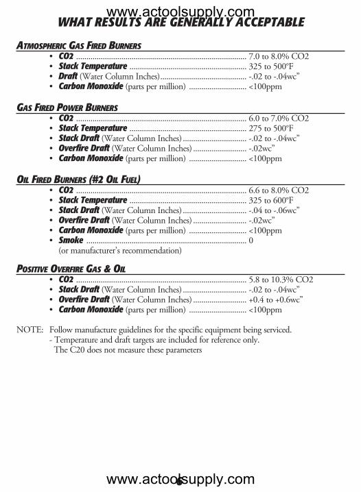
atmoSpheriC gaS fired burNerS • CO2 ...................................................................................7.0to8.0%CO2 • Stack Temperature .........................................................325to500°F • Draft (WaterColumnInches) ..........................................-.02to-.04wc” • Carbon Monoxide(partspermillion) ............................<100ppm
gaS fired power burNerS • CO2 ...................................................................................6.0to7.0%CO2 • Stack Temperature .........................................................275to500°F • Stack Draft (WaterColumnInches) ...............................-.02to-.04wc” • Overfire Draft (WaterColumnInches) ..........................-.02wc” • Carbon Monoxide(partspermillion) ............................<100ppm
oil fired burNerS (#2 oil fuel) • CO2 ...................................................................................6.6to8.0%CO2 • Stack Temperature .........................................................325to600°F • Stack Draft (WaterColumnInches) ...............................-.04to-.06wc” • Overfire Draft (WaterColumnInches) ..........................-.02wc” • Carbon Monoxide(partspermillion) ............................<100ppm • Smoke ..............................................................................0 (ormanufacturer’srecommendation)
poSitive overfire gaS & oil • CO2 ...................................................................................5.8to10.3%CO2 • Stack Draft (WaterColumnInches) ...............................-.02to-.04wc” • Overfire Draft (WaterColumnInches) ..........................+0.4to+0.6wc” • Carbon Monoxide(partspermillion) ............................<100ppm
NOTE: Followmanufactureguidelinesforthespecificequipmentbeingserviced. - Temperature and draft targets are included for reference only. TheC20doesnotmeasuretheseparameters
WHAT RESULTS ARE GENERALLY ACCEPTABLEwww.actoolsupply.com
www.actoolsupply.com
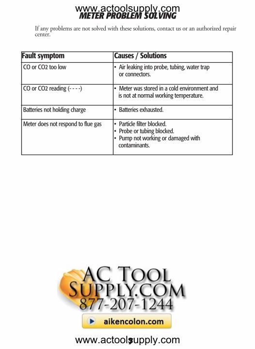
METER PROBLEM SOLVING If any problems are not solved with these solutions, contact us or an authorized repair center.
Fault symptom Causes / Solutions CO or CO2 too low • Air leaking into probe, tubing, water trap or connectors.
CO or CO2 reading (- - - -) • Meter was stored in a cold environment and is not at normal working temperature. Batteries not holding charge • Batteries exhausted.
Meter does not respond to flue gas • Particle filter blocked. • Probe or tubing blocked. • Pump not working or damaged with contaminants.
7
www.actoolsupply.com
www.actoolsupply.com
8
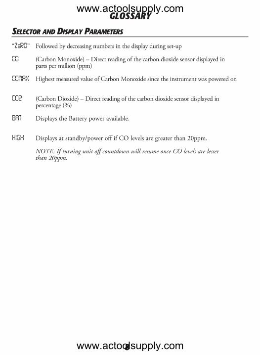
SeleCtor aNd diSplay parameterS “ZeRO” Followed by decreasing numbers in the display during set-up
CO (CarbonMonoxide)–Directreadingofthecarbondioxidesensordisplayedin partspermillion(ppm)
COMAX HighestmeasuredvalueofCarbonMonoxidesincetheinstrumentwaspoweredon
CO2 (CarbonDioxide)–Directreadingofthecarbondioxidesensordisplayedin percentage(%)
BAT DisplaystheBatterypoweravailable.
HIGH Displaysatstandby/poweroffifCOlevelsaregreaterthan20ppm. NOTE: If turning unit off countdown will resume once CO levels are lesser than 20ppm.
GLOSSARYwww.actoolsupply.com
www.actoolsupply.com
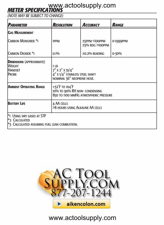
parameter reSolutioN aCCuraCy raNge
Gas MeasureMent
Carbon Monoxide *1 1ppm ±5ppm <100ppm 0-1999ppm ±5% rdg >100ppm
Carbon Dioxide *1 0.1% ±0.2% reading 0-30%
DiMensions (approximate) Weight 1 lbHandset 7” x 2” x 31/4”Probe 4” x 1/4” stainless steel shaft nominal 36” neoprene hose.
aMbient operatinG ranGe +32˚F to 104˚F 10% to 90% RH non- condensing 850 to 1100 mmHg atmospheric pressure
battery Life 4 AA cells >8 hours using Alkaline AA cells
*1 Using dry gases at STP *2 Calculated*3 Calculated assuming fuel lean combustion.
meter SpeCifiCatioNS(NOTE MAY BE SUBJECT TO CHANGE)
www.actoolsupply.com
www.actoolsupply.com