Embed Size (px)
Citation preview

www.fieldcontrols.com
Please retain these instructions after installation.
This device MUST be installed by a qualified agency in accordance with the manufacturer's installation instructions. The definition of a qualified agency is: any individual, firm, corporation or company which either in person or through a representative is engaged in, and is responsible for, the installation and operation of HVAC appliances, who is experienced in such work, familiar with all the precautions required, and has complied with all the requirements of the authority having jurisdiction.
READ THESE INSTRUCTIONS CAREFULLY AND COMPLETELY BEFORE PROCEEDING WITH THE INSTALLATION.
Installation Date:Installed By: Phone:
COMBUSTION AIR SYSTEMModel: CAS-3
This product is designed for use with any oil burning furnace, water heater, or boiler with 120 VAC control systems. It may also be used with more than one appliance. The CAS unit mechanically draws air into a structure and disperses it near the combustion air intake of an appliance. If an optional Vacuum Relief Valve (VRV) is used, the incoming air is tempered before entering the structure’s airspace. Refer to Diagram A and B for guidance in setting up the CAS system based on the size and length of the connecting ductwork and the input rating of the appliance.
ITEMS INCLUDED IN KIT: 1- Motorized Blower 1- 4" galvanized intake air Vent Hood 2- Mounting Brackets to secure the CAS to a wall 2- Wire/Conduit connectors 1- 4" x 6" Pipe Increaser Fitting 1- 6" Orifice Ring 1- Instruction Sheet 1- High/Low Motor Speed Switch

page 2
SIZING AND SETUP Diagrams A and B and Table 1 shows the maximum equivalent length and size of duct pipe that should be used when installing the CAS system. Using these charts will help ensure that the proper amount of air is drawn into the structure as needed by the appliance. The defined regions shown correspond to the CAS's airflow characteristics when using 4" and 6" diameter sheet metal duct pipe and the included orifice ring. Follow the guidelines below to properly size and setup the CAS.
Determine the maximum input firing rate of the appliance, or the maximum total firing rate of multiple 1. appliances that will be used. Position the motorized CAS unit according to the guidelines in the "Installation" section. 2. Determine where the intake air vent hood will be located based on the recommendations in the 3. "Installation" section. The CAS is equipped with a High/Low motor speed control switch. When calculating the maximum 4. equivalent feet, determine which speed is appropriate for the application. (Refer to Diagram A or B or Table 1) Calculate the total equivalent length of duct pipe including elbows and fittings needed to connect the 5. CAS unit to the vent hood. (Refer to Diagram A or B or Table 1) On Diagram A or B, locate the point that corresponds to the firing rate along the horizontal axis and the 6. equivalent length of the duct pipe along the vertical axis, if using for Make-Up air. The point should fall within one of the three regions on the table. Each region corresponds to a duct pipe 7. diameter of 4", 4" using the orifice ring, and 6" respectively. If the point falls near the rightward border of a particular region then the VRV is not necessary. If the point falls away from the rightward border, then a VRV is needed to reduce the amount of air drawn in.Draw a horizontal line on Diagram A or B that passes through the point located in step 5. The position of 8. the point along this line relative to the left and right borders of the region it falls into indicates the relative position that the balance weight of the VRV should be adjusted to. If the point falls near the leftward border of a region, then the VRV balance weight should be adjusted to its minimum position. This corresponds to turning the balance weight screw as far counterclockwise as possible.
GENERAL SYSTEM OPERATION The thermostat (wall thermostat, or aquastat) calls for heat and energizes a relay which activates the 1. CAS unit. After the CAS fan has come up to speed, an internal air pressure switch closes and completes the circuit to allow the burner to fire. If the appliance is power vented, the venter and CAS activate simultaneously. After the CAS comes up to speed, a pressure switch in the unit closes and allows the appliance to fire. After the heating requirement has been satisfied, the thermostat circuit will open and deactivate the 2. burner and CAS unit. For power vented systems with a post purge device, the power venter and CAS operate for a period of 3. time after the burner has shut off to purge remaining flue gases from the vent system.
INSTALLATION SAFETY INSTRUCTIONS
CAUTION: This device must be installed by a qualified installer in accordance with the manufacturer’s installation instructions.
This combustion air system must be installed by a qualified installer. “Qualified Installer” shall mean 1. an individual who has been properly trained or a licensed installer. Plan the system layout before installation to avoid the possibility of accidental contact with 2. concealed wiring or plumbing inside walls. Disconnect power supply before making wiring connections to prevent electrical shock and 3. equipment damage.

page 3
EXAMPLE: An oil fired appliance firing at 1.0 gph where the CAS unit needs to be placed 30 equivalent feet from the intake hood. From Diagram A or B, the point at 1.0 gph on the "Oil Firing Rate" scale and 30 equivalent feet falls in the 4" Duct, Hood, and Orifice Ring region. The point is in between the left and right boundary of the region. The left boundary is the edge of the graph, the right boundary is the diagonal line that says 4" Duct, Hood & Orifice Ring. Therefore, place the Orifice Ring into the inlet on the CAS so that it sits on the ledge above the fan. It does not matter which way the Orifice Ring is turned as long as it is pushed down against the ledge completely. Use 4" diameter pipe to connect the vent hood and the CAS unit. Install a VRV and the included 4" x 6" Increaser on top of the CAS unit and adjust the balance weight to 3⁄4 of the distance of its full adjustment range from its minimum setting. The minimum setting is with the balance weight turned all of the way counterclockwise.
TOTAL INPUT OF APPLIANCE MAXIMUM EqUIvALENT FEET OF INSTALLATION
CAS-3Oil (gph)
4" Duct And Hood w/Restrictor
4" Duct And 4" Intake Air Hood
6" Duct And 6"Intake Air Hood
HI LOW HI LOW HI LOW
0.50 300 300 300 300 300 300
0.75 300 300 300 300 300 300
0.90 300 220 300 220 300 300
1.00 174 108 232 118 300 300
1.25 99 48 152 63 300 300
1.35 52 14 102 32 300 300
1.55 20 NA 68 13 300 239
1.75 NA NA 45 NA 300 150
2.00 NA NA 16 NA 300 53
2.50 NA NA NA NA 193 8
2.75 NA NA NA NA 109 NA
3.25 NA NA NA NA 56 NA
Table 1

page 4
Diagram A
LOW SPEED SIZING CHART
0
50
100
150
200
250
300
50 100 150 200 250 300 350 400GAS INPUT FIRING RATE (1000 BTU/hr.)
MA
X.E
QU
IVA
LE
NT
DU
CT
LE
NG
TH
(ft.
)
0.0 0.50 1.00 1.50 2.00 2.50
OIL INPUT FIRING RATE (gallons per hour)(1 gallon oil/hr = 140,000 BTU/hr.)
6" Duct & Hood
4" Duct & Hood
4" Duct & Hood w/ Orifice
Diagram B

page 5
INSTALLATION PLACEMENT OF THE CAS UNIT The motorized CAS unit should be located on a flat horizontal surface within the space of the appliance or appliances, and try to be within 3' of the combustion air intake of the appliance. Two mounting brackets are provided for securing the unit against a solid structure, such as a wall, column, or the side of the appliance itself. Use the included screws to attach the brackets to the CAS housing as shown in Figure 1. Secure the brackets to a solid structure with appropriate fasteners. It is not required to use the brackets as long as the unit is located so that it may not be bumped, moved, or tipped over. The optional Vacuum Relief Valve (VRV) should be placed directly on the air inlet of the CAS unit if using 6" duct or if using 4" duct, should be placed above reducer. (See Figure 2) Refer to Diagram A to determine if the VRV is needed. The VRV should be oriented so that the axis of the swinging gate is horizontal.
ASSEMBLING THE WEIGHTS ON THE vRv Refer to Figure 3 to assemble the weight assembly, hex nut, and knurled nut to the VRV gate. After the weight is correctly positioned, tighten the hex nut against the gate to prevent the weight assembly from moving during operation.
INTAKE AIR HOOD LOCATION The 4" galvanized vent hood should be located on an outside wall maintaining minimum clearances to other intake and exhaust vents in accordance with the National Fuel Gas Code, ANSI Z223.1, manufacturer's recommendations and/or local codes which are applicable. The hood should be located at least 10' from a power vented exhaust outlet and should be on the same wall.
Figure 1
Figure 2

page 6
INSTALLATION OF INTAKE AIR HOOD After determining the location of the vent hood, cut a 4 1⁄2" round or square hole in the wall. Insert the vent hood and secure with appropriate fasteners. Take precautions to avoid interference with wiring or other plumbing in the wall to be cut.
INSTALLATION OF DUCT Refer to Diagram A or B to determine what size pipe is needed. Connect the duct pipe from the top of the CAS unit to the Vent Hood in the wall. If using 4" diameter pipe attach the provided 4" x 6" Pipe lncreaser Fitting to the top of the CAS unit. The duct should be supported with appropriate mounting straps from floor joists, walls, or other solid structures. The straps should be placed so as to keep the ductwork out of passageways. (See Figure 2) A minimum of 12' of pipe should be run to help temper outside air being drawn in. The VRV may also be installed near the air intake hood and adjusted to mix with outside air to help temper air in cold climates.
Figure 3

page 7
WIRING INSTRUCTIONS Wire the CAS unit in accordance with the National Electric Code and applicable local codes. UNIT MUST BE GROUNDED. Check the ground circuit to make certain that the unit has been properly grounded. The wiring should be protected by an over-current circuit device rated at 15 amperes. CAUTION must be taken to ensure that the wiring does not come in contact with any heat source. All line voltage and control circuits between the CAS unit and the appliance MUST be wired in accordance with the National Electrical Code for Class I wiring or equivalent.
Remove the wiring access cover to access the wiring terminals. Use the enclosed conduit connector(s) to route the appropriate wires through the CAS housing. The incoming ground wire must be attached to the green colored ground screw near the wire terminals. The following sections describe the most common applications. The references to various series of control kits implies that any kit in that series may be used.If further information or additional wiring diagrams are needed please consult Field Controls’ technical support.
INTERNAL WIRING CONNECTIONS FOR THE CAS UNIT Refer to Figure 4 for the internal wiring of the CAS-3 unit.
WIRE KEY WIRE COLOR
Motor Manufacturer W1 W2 W3McLean Engineering Black Blue Brown
All Others Brown Black Blue
Figure 4

page 8
Figure 5- Chimney Vent Single Oil Fired System
Figure 6- Riello Oil Fired System
EXTERNAL WIRING CONNECTIONS Refer to Figures 5-9 for appropriate wiring method.

page 9
Figure 7- Single Vent Oil Fired System

page 10
Figure 8- Chimney Vent Two Oil Fired System with CAC-120
page 11
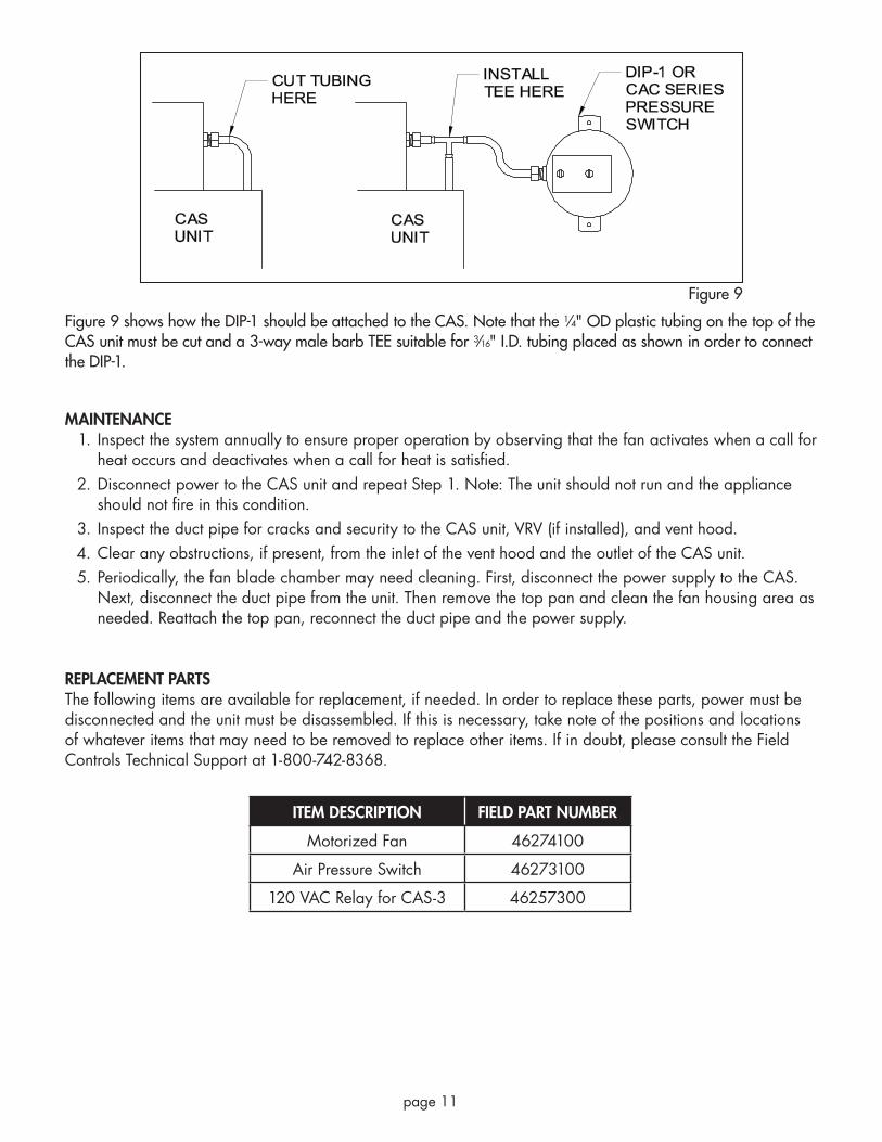
Figure 9 shows how the DIP-1 should be attached to the CAS. Note that the 1⁄4" OD plastic tubing on the top of the CAS unit must be cut and a 3-way male barb TEE suitable for 3⁄16" I.D. tubing placed as shown in order to connect the DIP-1.
MAINTENANCEInspect the system annually to ensure proper operation by observing that the fan activates when a call for 1. heat occurs and deactivates when a call for heat is satisfied.Disconnect power to the CAS unit and repeat Step 1. Note: The unit should not run and the appliance 2. should not fire in this condition.Inspect the duct pipe for cracks and security to the CAS unit, VRV (if installed), and vent hood.3. Clear any obstructions, if present, from the inlet of the vent hood and the outlet of the CAS unit.4. Periodically, the fan blade chamber may need cleaning. First, disconnect the power supply to the CAS. 5. Next, disconnect the duct pipe from the unit. Then remove the top pan and clean the fan housing area as needed. Reattach the top pan, reconnect the duct pipe and the power supply.
REPLACEMENT PARTS The following items are available for replacement, if needed. In order to replace these parts, power must be disconnected and the unit must be disassembled. If this is necessary, take note of the positions and locations of whatever items that may need to be removed to replace other items. If in doubt, please consult the Field Controls Technical Support at 1-800-742-8368.
ITEM DESCRIPTION FIELD PART NUMBER
Motorized Fan 46274100
Air Pressure Switch 46273100
120 VAC Relay for CAS-3 46257300
Figure 9

Phone: 252.522.3031 • Fax: 252.522.0214www.fieldcontrols.com
© Field Controls, LLC P/N 46261200 Rev J 11/09
LIMITED WARRANTY
Field Controls, LLC (“Company”) warrants that its products shall be free from defects in material and workmanship under normal use for the limited period indicated, from the date of manufacture, subject to the provisions 1-8 below. Eighteen (18) months All Field Controls Products (except for those listed below as 5 years or 90 days). Five (5) years Field Controls Direct Vent Systems (FDVS), Field Oil Vent Kits (FOVP), and ComboVents (CV).
Field Controls warrants that the products listed below shall be free from defects in material and workmanship under normal use for the limited period indicated, from the date of purchase by the consumer, subject to the provisions 1-8 below.
Ninety (90) days UV lamps/bulbs
Provisions:1. During the limited warranty period, Company, or its authorized service representative, will repair or replace, at Company’s option, without charge, a defective Product. Product that is repaired may be repaired with new or refurbished replacement parts. Product that is replaced may be replaced with a new or refurbished product of the same or similar design. Company will return repaired or replacement Product to customer in working condition. Labor charges are not covered as part of the limited warranty.
2. With regard to UV lamps/bulbs, customer shall be required to include a "valid proof of purchase" (sales receipt) identifying the Product purchased (Product model or accurate date code information) and the date the Product(s) was purchased.
3. Product whose warranty/quality stickers, Product serial number plates or electronic serial numbers have been removed, altered or rendered illegible shall not be covered under the limited warranty.
4. Defective Product must be returned to Company, postage prepaid.
5. IN NO EVENT SHALL COMPANY BE LIABLE FOR ANY INDIRECT, SPECIAL, INCIDENTAL, CONSEQUENTIAL, OR SIMILAR DAMAGES (INCLUDING, BUT NOT LIMITED TO, LOST PROFITS OR REVENUE, INABILITY TO USE PRODUCT, OR OTHER ASSOCIATED EQUIPMENT, THE COST OF SUBSTITUTE EQUIPMENT, AND CLAIMS BY THIRD PARTIES) RESULTING FROM THE USE OF PRODUCT. Some states do not allow the exclusion or limitation of incidental or consequential damages, so the above limitation or exclusion may not apply to you.
6. THIS WARRANTY AND REMEDIES ARE EXCLUSIVE AND IN LIEU OF ALL OTHER WARRANTIES, REMEDIES AND CONDITIONS, WHETHER ORAL, WRITTEN, EXPRESS, STATUTORY OR IMPLIED. TO THE EXTENT PERMITTED BY LAW, COMPANY DISCLAIMS ALL IMPLIED AND STATUTORY WARRANTIES, INCLUDING WARRANTIES OF MERCHANTABILITY AND FITNESS FOR A PARTICULAR PURPOSE.
7. Company makes no warranty of any kind in regard to other manufacturer’s products distributed by Company. Company will pass on all warranties made by the manufacturer and where possible, will expedite the claim on behalf of the customer, but ultimately, responsibility for disposition of the warranty claim lies with the manufacturer.
8. Product that has been subjected to misuse, accident, shipping or other physical damage, improper installation or application, abnormal operation or handling, neglect, fire, water or other liquid intrusion are not covered by the warranty.