Embed Size (px)
Citation preview
CERV® Fan and Duct Sizing Information
Scope
Duct design for distributing fresh air and exhausting house air requires two considerations:
1) Sufficiently large ducts for available fan static pressure
2) Sufficiently low air velocities to minimize noise
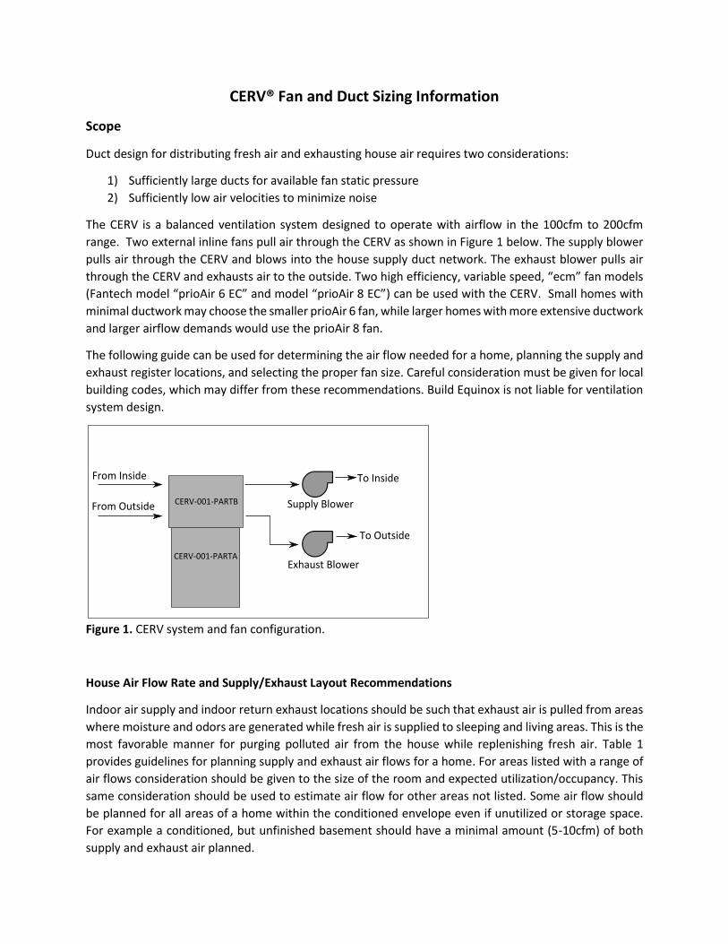
The CERV is a balanced ventilation system designed to operate with airflow in the 100cfm to 200cfm
range. Two external inline fans pull air through the CERV as shown in Figure 1 below. The supply blower
pulls air through the CERV and blows into the house supply duct network. The exhaust blower pulls air
through the CERV and exhausts air to the outside. Two high efficiency, variable speed, “ecm” fan models
(Fantech model “prioAir 6 EC” and model “prioAir 8 EC”) can be used with the CERV. Small homes with
minimal ductwork may choose the smaller prioAir 6 fan, while larger homes with more extensive ductwork
and larger airflow demands would use the prioAir 8 fan.
The following guide can be used for determining the air flow needed for a home, planning the supply and
exhaust register locations, and selecting the proper fan size. Careful consideration must be given for local
building codes, which may differ from these recommendations. Build Equinox is not liable for ventilation
system design.
Figure 1. CERV system and fan configuration.
House Air Flow Rate and Supply/Exhaust Layout Recommendations
Indoor air supply and indoor return exhaust locations should be such that exhaust air is pulled from areas
where moisture and odors are generated while fresh air is supplied to sleeping and living areas. This is the
most favorable manner for purging polluted air from the house while replenishing fresh air. Table 1
provides guidelines for planning supply and exhaust air flows for a home. For areas listed with a range of
air flows consideration should be given to the size of the room and expected utilization/occupancy. This
same consideration should be used to estimate air flow for other areas not listed. Some air flow should
be planned for all areas of a home within the conditioned envelope even if unutilized or storage space.
For example a conditioned, but unfinished basement should have a minimal amount (5-10cfm) of both
supply and exhaust air planned.
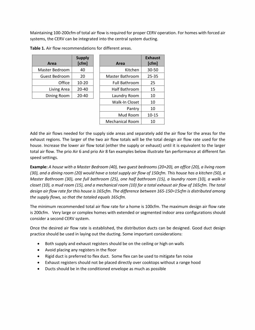
Maintaining 100-200cfm of total air flow is required for proper CERV operation. For homes with forced air
systems, the CERV can be integrated into the central system ducting.
Table 1. Air flow recommendations for different areas.
Area Supply [cfm] Area
Exhaust [cfm]
Master Bedroom 40 Kitchen 30-50
Guest Bedroom 20 Master Bathroom 25-35
Office 10-20 Full Bathroom 25
Living Area 20-40 Half Bathroom 15
Dining Room 20-40 Laundry Room 10
Walk-In Closet 10
Pantry 10
Mud Room 10-15
Mechanical Room 10
Add the air flows needed for the supply side areas and separately add the air flow for the areas for the
exhaust regions. The larger of the two air flow totals will be the total design air flow rate used for the
house. Increase the lower air flow total (either the supply or exhaust) until it is equivalent to the larger
total air flow. The prio Air 6 and prio Air 8 fan examples below illustrate fan performance at different fan
speed settings.
Example: A house with a Master Bedroom (40), two guest bedrooms (20+20), an office (20), a living room
(30), and a dining room (20) would have a total supply air flow of 150cfm. This house has a kitchen (50), a
Master Bathroom (30), one full bathroom (25), one half bathroom (15), a laundry room (10), a walk-in
closet (10), a mud room (15), and a mechanical room (10) for a total exhaust air flow of 165cfm. The total
design air flow rate for this house is 165cfm. The difference between 165-150=15cfm is distributed among
the supply flows, so that the totaled equals 165cfm.
The minimum recommended total air flow rate for a home is 100cfm. The maximum design air flow rate
is 200cfm. Very large or complex homes with extended or segmented indoor area configurations should
consider a second CERV system.
Once the desired air flow rate is established, the distribution ducts can be designed. Good duct design
practice should be used in laying out the ducting. Some important considerations:
Both supply and exhaust registers should be on the ceiling or high on walls
Avoid placing any registers in the floor
Rigid duct is preferred to flex duct. Some flex can be used to mitigate fan noise
Exhaust registers should not be placed directly over cooktops without a range hood
Ducts should be in the conditioned envelope as much as possible
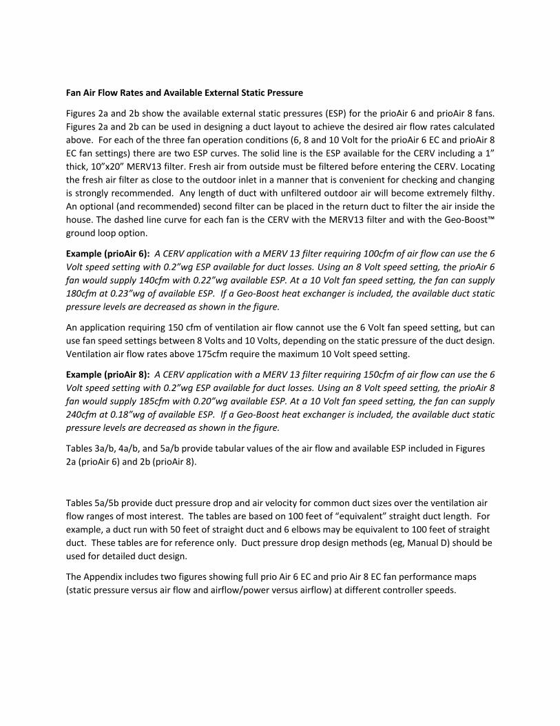
Fan Air Flow Rates and Available External Static Pressure
Figures 2a and 2b show the available external static pressures (ESP) for the prioAir 6 and prioAir 8 fans.
Figures 2a and 2b can be used in designing a duct layout to achieve the desired air flow rates calculated
above. For each of the three fan operation conditions (6, 8 and 10 Volt for the prioAir 6 EC and prioAir 8
EC fan settings) there are two ESP curves. The solid line is the ESP available for the CERV including a 1”
thick, 10”x20” MERV13 filter. Fresh air from outside must be filtered before entering the CERV. Locating
the fresh air filter as close to the outdoor inlet in a manner that is convenient for checking and changing
is strongly recommended. Any length of duct with unfiltered outdoor air will become extremely filthy.
An optional (and recommended) second filter can be placed in the return duct to filter the air inside the
house. The dashed line curve for each fan is the CERV with the MERV13 filter and with the Geo-Boost™
ground loop option.
Example (prioAir 6): A CERV application with a MERV 13 filter requiring 100cfm of air flow can use the 6
Volt speed setting with 0.2”wg ESP available for duct losses. Using an 8 Volt speed setting, the prioAir 6
fan would supply 140cfm with 0.22”wg available ESP. At a 10 Volt fan speed setting, the fan can supply
180cfm at 0.23”wg of available ESP. If a Geo-Boost heat exchanger is included, the available duct static
pressure levels are decreased as shown in the figure.
An application requiring 150 cfm of ventilation air flow cannot use the 6 Volt fan speed setting, but can
use fan speed settings between 8 Volts and 10 Volts, depending on the static pressure of the duct design.
Ventilation air flow rates above 175cfm require the maximum 10 Volt speed setting.
Example (prioAir 8): A CERV application with a MERV 13 filter requiring 150cfm of air flow can use the 6
Volt speed setting with 0.2”wg ESP available for duct losses. Using an 8 Volt speed setting, the prioAir 8
fan would supply 185cfm with 0.20”wg available ESP. At a 10 Volt fan speed setting, the fan can supply
240cfm at 0.18”wg of available ESP. If a Geo-Boost heat exchanger is included, the available duct static
pressure levels are decreased as shown in the figure.
Tables 3a/b, 4a/b, and 5a/b provide tabular values of the air flow and available ESP included in Figures
2a (prioAir 6) and 2b (prioAir 8).
Tables 5a/5b provide duct pressure drop and air velocity for common duct sizes over the ventilation air
flow ranges of most interest. The tables are based on 100 feet of “equivalent” straight duct length. For
example, a duct run with 50 feet of straight duct and 6 elbows may be equivalent to 100 feet of straight
duct. These tables are for reference only. Duct pressure drop design methods (eg, Manual D) should be
used for detailed duct design.
The Appendix includes two figures showing full prio Air 6 EC and prio Air 8 EC fan performance maps
(static pressure versus air flow and airflow/power versus airflow) at different controller speeds.

Figure 2a. CERV air flow rates versus available external static pressure for Fantech “prioAir 6 EC” fan at 6
volts, 8 volts and 10 volts settings.
Figure 2b. CERV air flow rates versus available external static pressure for Fantech “prioAir 8 EC” fan at 6
volts, 8 volts and 10 volts settings.

Table 2a. Fantech prioAir 6 EC at 6 Volt setting airflow and available external static pressure.
prio 6 6Volts prio 6 6Volts
MERV13 filter MERV13 filter
AirFlow Geo-Boost
cfm "wg "wg
100 0.20 0.17
110 0.14 0.09
125 0.03
Table 2b. Fantech prioAir 8 EC at 6 Volt setting airflow and available external static pressure.
prio 8 6Volts prio 8 6Volts
MERV13 filter MERV13 filter
AirFlow Geo-Boost
cfm "wg "wg
100 0.97 0.93
110 0.79 0.74
120 0.61 0.55
130 0.45 0.37
140 0.30 0.20
150 0.15 0.04
160 0.01
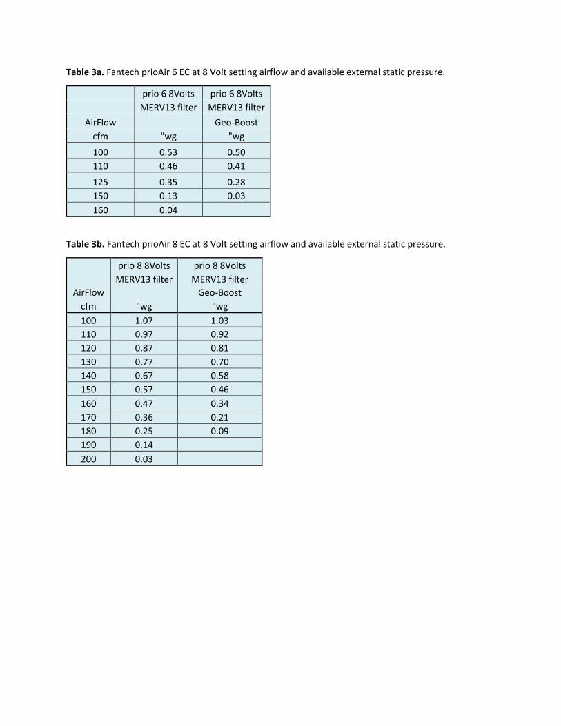
Table 3a. Fantech prioAir 6 EC at 8 Volt setting airflow and available external static pressure.
prio 6 8Volts prio 6 8Volts
MERV13 filter MERV13 filter
AirFlow Geo-Boost
cfm "wg "wg
100 0.53 0.50
110 0.46 0.41
125 0.35 0.28
150 0.13 0.03
160 0.04
Table 3b. Fantech prioAir 8 EC at 8 Volt setting airflow and available external static pressure.
prio 8 8Volts prio 8 8Volts
MERV13 filter MERV13 filter
AirFlow Geo-Boost
cfm "wg "wg
100 1.07 1.03
110 0.97 0.92
120 0.87 0.81
130 0.77 0.70
140 0.67 0.58
150 0.57 0.46
160 0.47 0.34
170 0.36 0.21
180 0.25 0.09
190 0.14
200 0.03

Table 4a. Fantech prioAir 6 EC at 10 Volt setting airflow and available external static pressure.
prio 6 10Volts prio 6 10Volts
MERV13 filter MERV13 filter
AirFlow Geo-Boost
cfm "wg "wg
100 0.85 0.82
110 0.79 0.74
125 0.69 0.62
150 0.50 0.39
160 0.42 0.29
180 0.24 0.07
200 0.04
Table 4b. Fantech prioAir 8 EC at 10 Volt setting airflow and available external static pressure.
prio 8 10Volts prio 8 10Volts
MERV13 filter MERV13 filter
AirFlow Geo-Boost
cfm "wg "wg
100 1.42 1.38
110 1.37 1.32
120 1.31 1.25
130 1.24 1.17
140 1.17 1.08
150 1.10 0.99
160 1.01 0.89
170 0.93 0.78
180 0.83 0.67
190 0.74 0.55
200 0.63 0.42
210 0.52 0.29
220 0.41 0.15
230 0.29 0.01
240 0.17
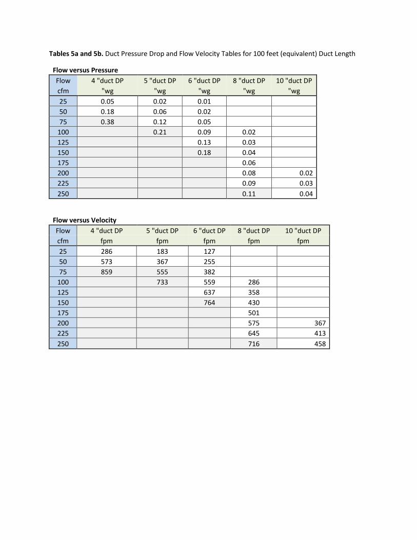
Tables 5a and 5b. Duct Pressure Drop and Flow Velocity Tables for 100 feet (equivalent) Duct Length
Flow versus Pressure
Flow 4 "duct DP 5 "duct DP 6 "duct DP 8 "duct DP 10 "duct DP
cfm "wg "wg "wg "wg "wg
25 0.05 0.02 0.01
50 0.18 0.06 0.02
75 0.38 0.12 0.05
100 0.21 0.09 0.02
125 0.13 0.03
150 0.18 0.04
175 0.06
200 0.08 0.02
225 0.09 0.03
250 0.11 0.04
Flow versus Velocity
Flow 4 "duct DP 5 "duct DP 6 "duct DP 8 "duct DP 10 "duct DP
cfm fpm fpm fpm fpm fpm
25 286 183 127
50 573 367 255
75 859 555 382
100 733 559 286
125 637 358
150 764 430
175 501
200 575 367
225 645 413
250 716 458
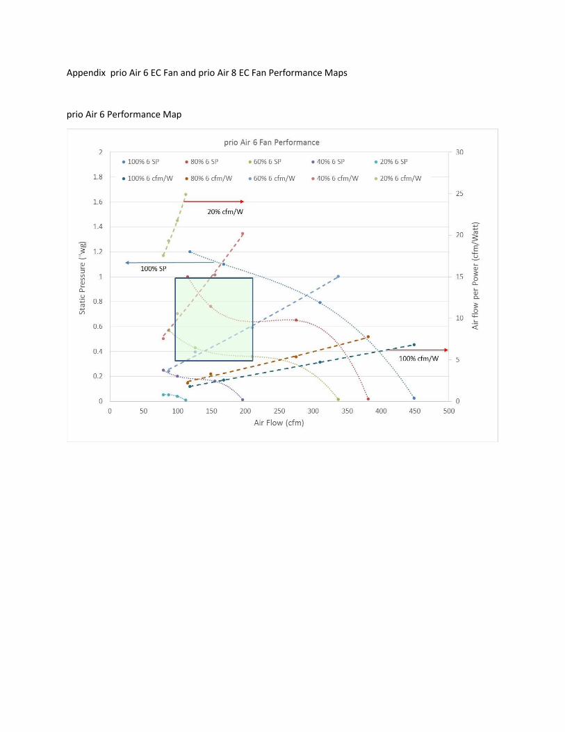
Appendix prio Air 6 EC Fan and prio Air 8 EC Fan Performance Maps
prio Air 6 Performance Map

prio Air 8 Performance Map