Embed Size (px)
Citation preview

t f ) V ~ , , L _,~I~('~s., . . . / ,F~ ,: ? a 5,:.:.::.,.,f~,;~:..~
M I N I S T R Y OF A V I A T I O N
R. & M. No. 3195 (20,373)
A.R.C. Technical Report
AERONAUTICAL RESEARCH COUNCIL
REPORTS AND MEMORANDA
Combined Flexure and Torsion of Class of Heated Thin Wings: A Large-Deflection Analysis
a
By E. H. MANSFIELD, S c . D .
LONDON: HER MAJESTY'S STATIONERY OFFICE
I96i
P R I C E I I S . 6d. N E T
Combined Flexure and Torsion of Class of Heated Thin Wings: A Large-Deflection Analysis
a
B y E . H . MANSFIELD, S c . D .
COMMUNICATED BY THE DIRECTOR-GENERAL OF SCIENTIFIC RESEARCH (AIR) MINISTRY OF ~UPPLY
Reports and Memoranda No. 3z95 *
March, z958
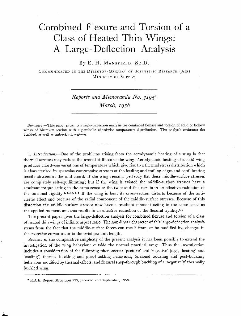
Summary . - -Th i s paper presents a large-deflection analysis for combined flexure and torsion of solid or hollow wings of biconvex section with a parabolic chordwise temperature distribution. The analysis embraces the buckled, as well as unbuckled, regimes.
1. I n t r o d u c t i o n . - - O n e of the problems arising from the aerodynamic heating of a wing is that thermal stresses may reduce the overall stiffness of the wing. Aerodynamic heating of a solid wing produces chordwise variations of temperature which give rise to a thermal stress distribution which is characterised by spanwise compressive stresses at the leading and trailing edges and equilibrating tensile stresses at the mid-chord. If the wing remains perfectly flat these middle-surface stresses are completely self-equilibrating; but if the wing is twisted the middle-surface stresses have a resultant torque acting in the same sense as the twist and this results in an effective reduction of the torsional rigidity. 1,2, 3,4, 5, 6 If the wing is bent its cross-section distorts because of the anti-
clastic effect and because of the radial component of the middle-surface stresses. Because of this
distortion the middle-surface stresses now have a result-ant moment acting in the same sense as
the applied moment and this results in an effective reduction of the flexural rigidity. 6, ~
The present paper gives the large-deflection analysis for combined flexure and torsion of a class
of heated thin wings of infinite aspect ratio. Thenon-linear character Of this large-deflection analysis
stems from the fact that the middle-surface forces can result from, or be modified by, changes in
the spanwise curvature or in the twist per unit length. Because of the comparative simplicity of the present analysis it has been possible to extend the
investigation of the wing behaviour outside the normal practical range. Thus the investigation
includes a consideration of the following phenomena: 'positive' and 'negative' (e.g., 'heating' and 'cooling') thermal buckling and post-buckling behaviour, torsional buckling and post-buckling
behaviour modified by thermal effects, and flexural snap-through buckling of a 'negatively' thermally
buckled wing.
* R.A.E. ReportStructures 237, received 2nd September, 1958.
k _

2. Method of Anc:lysis.--In order to determine the relationships between bending moment,
torque, spanwise curvature and twist it is first necessary to determine the chordwise distortion of the wing subject to a given (arbitrary) spanwise curvature and twist. The differential equation which governs this distortion is determined in Section 2.1. The solution of this differential equation for wings of parabolic lenticular section with a parabolic chordwise variation of temperature is given in Section 2.2. The strain energy per unit length of wing is then determined in Section 2.3 in terms of the spanwise curvature and twist; the bending moment and torque may thus be readily found by differentiation of the strain energy with respect to the curvature and twist.
2.1. Derivation of the Differential Equation.--The chordwise variation of the distortion of the wing may be determined most conveniently by variational methods. Consider first a wing with arbitrary chordwise thickness variation and arbitrary solidity subjected to a spanwise curvature K and twist per unit length 0. The distortion of the wing is then of the form
w(x,y) = ½Ky2 + Oxy+w(x), (1)
where the chordwise distortion of the wing w(x), hereafter referred to simply as w, may be determined from energy considerations.
The strain energy due to spanwise strains in the middle surface of the wing will now be deter-
mined. The first term on the right-hand side of equation (1) represents a developable surface and
therefore contributes no middle-surface strains. The second term i n equation (1) gives rise to 1 A2~2 spanwise strains that vary as ~ ~ . The final term in equation (1) gives rise to strains that vary
as -Kw. The spanwise strain (measured from a stress-free datum) is thus given by
E = g+½0~x~-Kw+A~+A~x, (2)
where the constants A 1 and A 2 are such that there is spanwise equilibrium, i.e.,
f a/2 t E d d x = 0 J - a12
f~/~ x E d d x = 0 d - - a/2
(3)
For simplicity equation (2) is written in the form
~ = e ' -Kw, (4)
where ~' is independent of w. There are no chordwise middle-surface stresses so the strain energy per unit length due to the middle-surface strains is given by
1 ~a12 g,, = ~- d ( e ' - K w ) 2 d x . (5)
d -at2 The strain energy per unit length due to flexure and torsion s is given by
b = ~ J_a/D[ {Ww(x,y)p-2( 1 - , ' ) a~w(.,ylax~ a~w(x,y)ay,. - t{a=w(x'Y)~--a~ &
= ~ J - a / ~ D l l ~ ) + 2vK-a~g + K= + 2(1 --~)0~/dx (6) by virtue of equation (1).
2

.The total strain energy per unit length is the sum of these two and the condition that this is a minimum with respect to w requires 9 w to satisfy the following differential equation
dx ~ D ~/~-+vK -- EKt(e'--Kw) = 0. (7)
The four boundary conditions appropriate to this equation express the fact that the leading and trailing edges are free, whence
• ( 8 )
I, 'K . ~ 0
Zx t \ dx~ ~= ±a12
2.2. Wings of Parabolic Lenticular Section and Parabolic Temperature Variation.--In this para- graph the solution of equation (7) will be derived for wings of solid section and for wings of thin walled section with a stabilising filling (so that the wing acts as a 'plate' instead of a hollow tube). Throughout it is assumed that Young's modulus E and the coefficient of thermal expansion ~ do
not vary with temperature. 2.2.1. Solid wings.--For such wings
'= 'o{1-
D = D o 1 - , ( 9 )
Eto a D o - 12(1_v2)
and if T " To+ TI(2~) +A T(2---~) 2, (10)
it follows from equations (2), (3) and (9) that
" i = aAT{1-(2--j)2}. (11)
In a similar manner it can be shown that
~' = i ~ 3 T - ~ - ) - , (12)
so that equation (7) becomes
D0 ~/~-2 [{ld~ -[y)[2x\~/~/d2w/t-d-~+ v,~)]
3
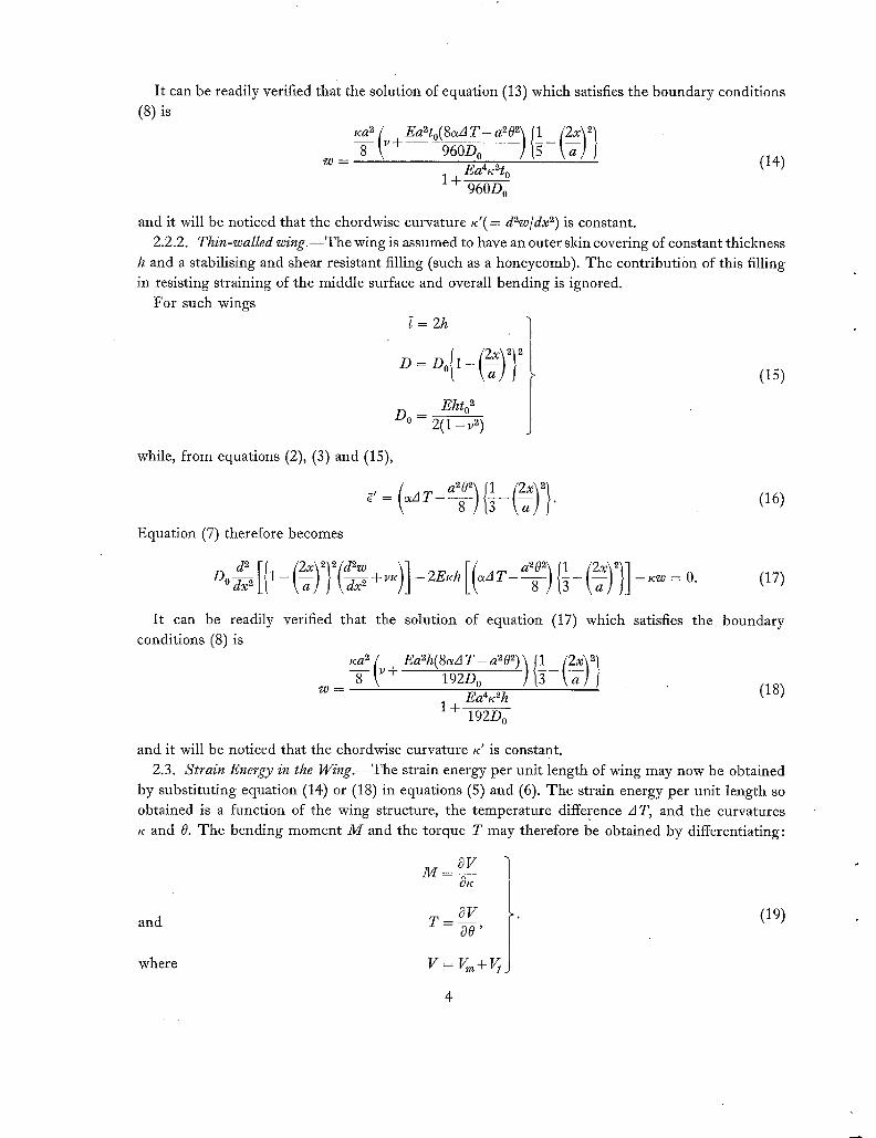
It can be readily verified that the solution of equation (13) which satisfies the boundary conditions (8) is
~ca ~ [ Ea~to(8C~d T - ~v-~ 960D ° a~O~] ig -~)2 t
~ ( l [2x\ ~
= ( 1 4 ) 1 -~ Ea4K2t°
960Do
and it will be noticed that the chordwise curvature K'(= d2w/dx ~) is constant. 2.2.2. Thin-walled wing.--The wing is assumed to have an outer skin covering of constant thickness
h and a stabilising and shear resistant filling (such as a honeycomb). The contribution of this filling in resisting straining of the middle surface and overall bending is ignored.
For such wings = 2h 1 j D = D0{1 - (~)2} ~ (15)
Ehto 2 Do 2 (1 -v 2)
while, from equations (2), (3) and (15),
Equation (7) therefore becomes
1 a202\ (16)
d 2 + 0 (17)
It can be readily conditions (8) is
verified that the solution of equation (17) which satisfies the boundary
Ka~ (v + Ea2h(8c"4 T - a~O ~)
w = Ea4~:2 h (18 ) 1-1-
192D o
and it will be noticed that the chordwise curvature •' is constant. 2.3. Strain Energy in the Wing.--The strain energy per unit length of wing may now be obtained
by substituting equation (14) or (18) in equations (5) and (6). The strain energy per unit length so obtained is a function of the wing structure, the temperature difference AT, and the curvatures x and 0. The bending moment M and the torque T may therefore be obtained by differentiating:
and
where
~9V T = ~ - ,
v= v +v j
(19)
4
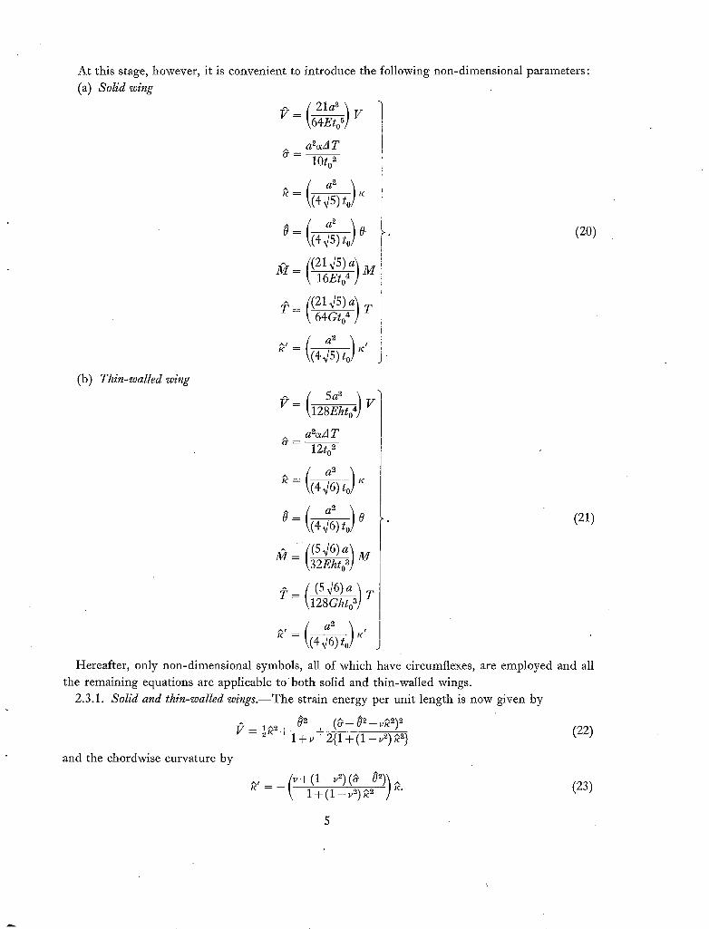
At this stage, however, it is convenient to introduce the following non-dimensional parameters: (a) Solid wing
[ 21a~ = \64Eto5] V
aZ~A T 10to 2
~ = tc
0=( (214s) a\ - ~-6~o4 ) M
2? = {!2145)a] k 64Gto 4 ] T
as
(445) t~o] K
~ =
~ , =
(b) Thin-walled wing
(20)
( 5a3 '~ (7 = \128Ehto ~] V
aZ~xA T 12to 2
4 x/6) t o
= 0 (21)
{(546)a] = [ ~ l M
~__ { (S46)a_] T \128Ghto 3]
Hereafter, only non-dimensional symbols, all of which have circumflexes, are employed and all the remaining equations are applicable t o both solid and thin-walled wings.
2.3.1. Solid and thin-walled wings.--The strain energy per unit length is now given by
p ½~z 02 ( O - 0 2 - v ~ ) 2 (22) = + f ~ + 2 { 1 + ( 1 - ~ , ~ ) ~ }
and the chordwise curvature by
U = - --- ^ \ 1+(1_v~)~2 ]K.
5
(23)
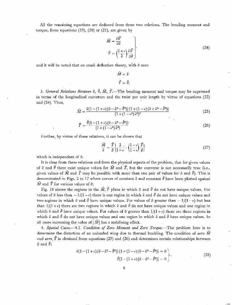
All the remaining equations are deduced from these two relations. The bending moment and torque, from equations (19), (20) or (21), are given by
(24)
and it will be noted that on small deflection theory, Mth ~ zero
Nr=
3. General Relations Between ~, 8, 2~r, 5~.--The bending moment and torque may be expressed in terms of the longitudinal curvature and the twist per unit length by virtue of equations .(22) and (24). Thus,
37I = ~c{1 - (1 + v) ( ~ - ~3 _ 03)} {1 + (1 - v) (~ + ~'c 3 - 03)} {1 + (1 - v 3) k3}~ (25)
A ^ 3 = 0{1 - (1 +v) ( ¢ - K - 03)} { 1 + ( 1 - v 3) ~3} (26)
Further, by virtue of these relations, it can be shown that
which is independent of " 17,
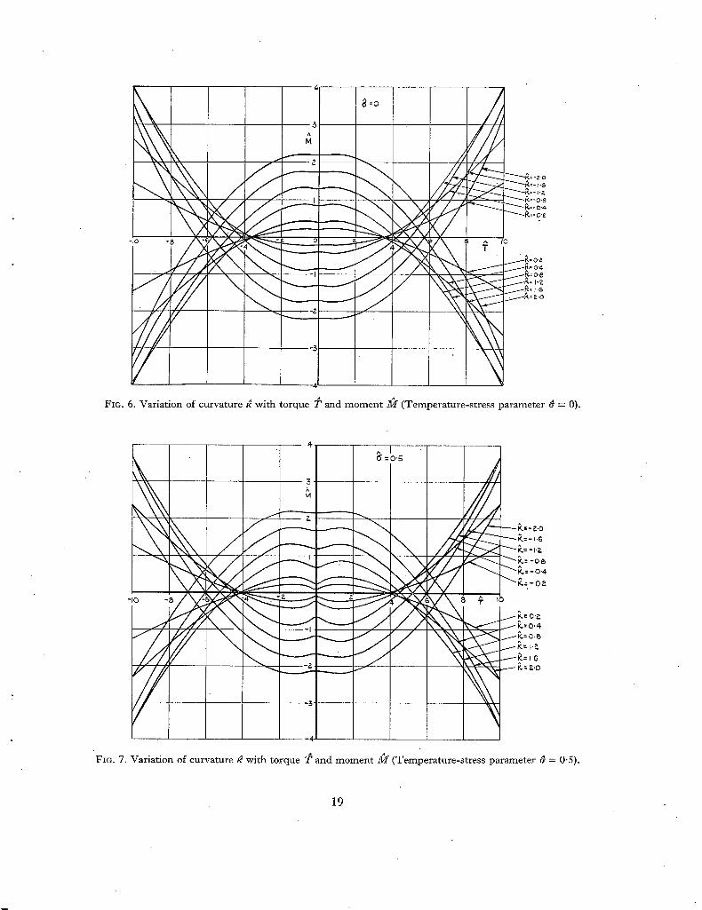
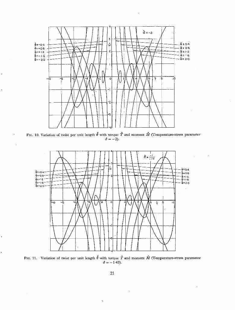
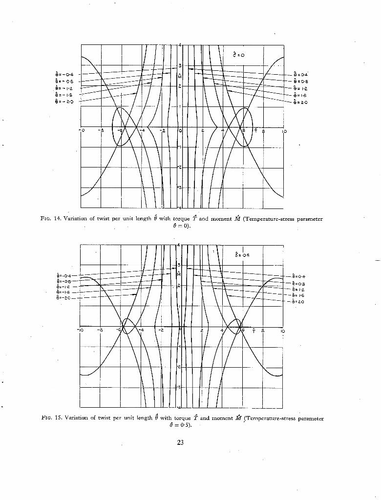
It is clear from these relations and from the physical aspects of the problem, that for given values of ~ and 0 there exist unique values for 2~/and 2P, but the converse is not necessarily true (i.e., given values of _M and T may be possible with more than one pair of values for ~ and 8). This is demonstrated in Figs. 2 to 17 where curves of constant ~ and constant 0 have been plotted against
and T for various values of & Fig. 18 shows the regions in the M, T plane in which ~ and 0 do not have unique values. For
values oi: 0 less than - 1/(1 - v ) there is one region in which ~ and 0 do not have unique values and two regions in which ~ and 0 have unique values. For values of ~ greater than - 1/(1 - v ) but less than 1/(1 +v) there are two regions in which ~ and 0 do not have unique values and one region in which ~ and 0 have unique values. For values of ~ greater than 1/(1 +v) there are three regions in which ~ and 0 do not have unique values and one region in which ~ and 0 have unique values. In
all cases increasing the value of I M I has a stabilising effect. 4. Special Cases.--4.1. Condition of Zero Moment and Zero Torque.--The problem here is to
determine the distortion of an unloaded wing due to thermal buckling. The condition of zero ~r and zero 2r is obtained from equations (25) and (26) and determines certain relationships between
and 0:
~{1 - (1 + v) (0 - ~3 _ 03)} {1 + (1 - v) (~ + ~3 _ 03)} = 0 } . (28)
8{1 - ( 1 + v) ( ~ - ~3 _ 03)} = 0
6
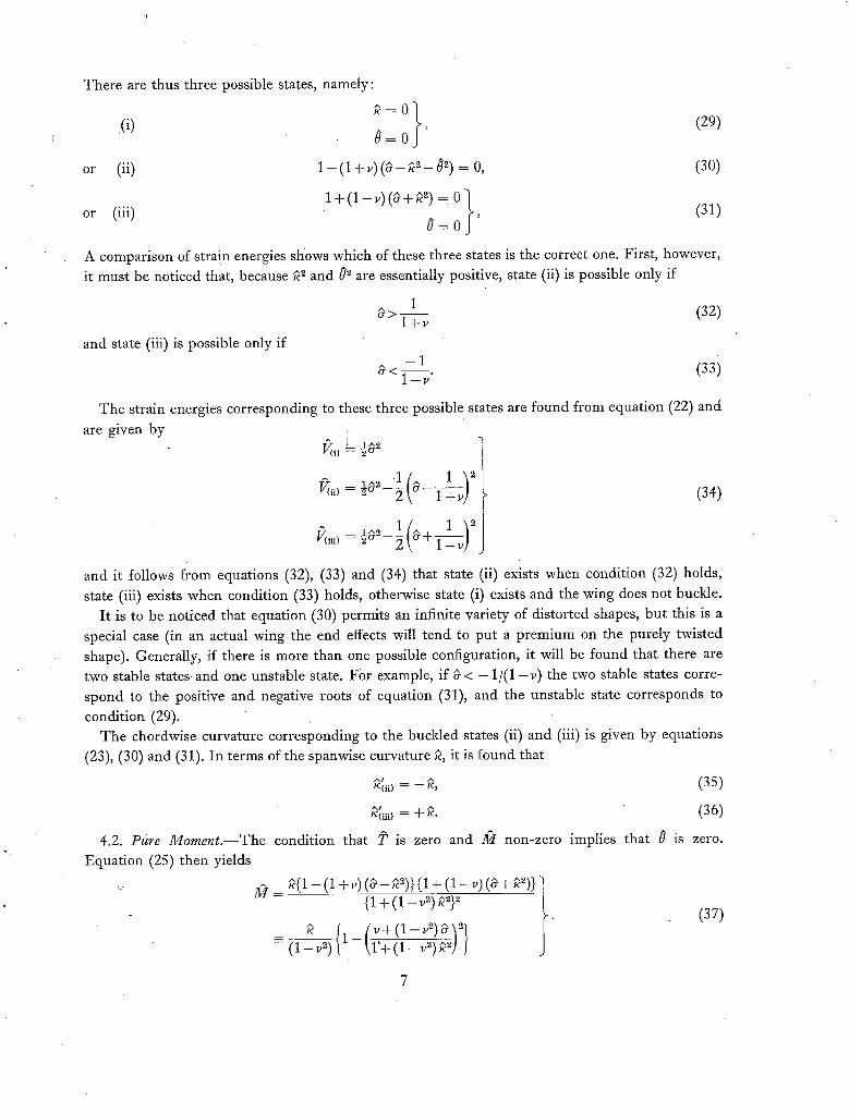
There are thus three possible states, namely:
= 0 } (29) (i) 0 = 0 '
^ ~ - = (30) or (ii) 1 - (1 + v) ( ~ - K 02) 0,
1 + ( 1 - v ) ( 9 + ~ 2) = 0"~ o r (iii) 0 0 (31)
= ~ '
A comparison of strain energies shows which of these three states is the correct one. First, however, it must be noticed that, because ~2 and 02 are essentially positive, state (ii) is possible only if
1 9 > - - - - (32) l + v
and state (iii) is possible only if - 1
9 < 1 -~" (33)
The strain energies corresponding to these three possible states are found from equation (22) and
are given by V(i) J ½a 2
V(ii) = ~c~ - ~ 9 - (34)
= ~o - ~ a + / c T _ ~
and it follows from equations (32), (33) and (34) that state (ii) exists when condition (32) holds, state (iii) exists when condition (33) holds, otherwise state (i) exists and the wing does not buckle.
It is to be noticed that equation (30) permits an infinite variety of distorted shapes, but this is a special case (in an actual wing the end effects will tend to put a premium on the purely twisted shape). Generally, if there is more than one possible configuration, it will be found that there are two stable states and one unstable state. For example, if 9 < - 1 / ( 1 - v) the two stable states corre- spond to the positive and negative roots of equation (31), and the unstable state corresponds to
condition (29). The chordwise curvature corresponding to the buckled states (ii) and (iii) is given by equations
(23), (30) and (31). In terms of the spanwise curvature ~, it is found that
" " (35) K ( i i ) ~ - - K ,
-"' " (36) K ( i i i ) = ÷ K .
4.2. Pure Moment . - -The condition that T is zero and _M non-zero implies that 0 is zero. Equation (25) then yields
. ~ = L{1 - (1_+ v ) ( a - ~2)} {1 + (1 - v) (a + ~ ) } {1 + (1 - v 2) ~}2
., . (37)
\ 1 . + ( 1 _ ~ 2 ) ~ 2 ! j

This bending moment-curvature relationship has been plotted in Fig. 19 for various values of 8. A number of special cases warrant attention. If there are no thermal stresses
(l_--v~) I - l+(l_v2)p{ 2 ,
which is the ordinary large-deflection solution. If
- - p
(38)
which corresponds to the solution on 'inextensional' plate theory. 1° The reason for this is that the radial component of the middle-surface stresses exactly counteracts the anti-clastic effect, so that ~' is zero. In general, as ~ increases the bending moment-curvature relationship tends towards equation (39), for all values of 9.
4.2.1. Snap-through flexural buchling.--If the wing was originally in state (iii) so that
- 1 }
1 ~1/2 ' (40) and ~o = + - "~- TZ~_ v)
a violent flexural instability will occur at a critical value of ]~ if ]~r and Pc o are of opposite sign (the mechanism of this instability is similar to that in a toy metal 'clicker'). For purposes of argument ~o will be assumed negative and ]~r positive. As _/17/increases ~ increases so that, because of the negative sign of ~o, I~1 decreases. But 2~ is zero when ~ is zero and therefore there is a critical negative value ~* at which the positive moment .g/* is a maximum. A further increase in the value of 37I causes the wing to snap through to a positive value of ~. It can be shown by differentiating equation (37) that
where /z = {v + ( 1 - v ~) 9} 9 f (41 )
and hence/14" can be determined.
4.2.2. Flexural rigidity.--A non-dimensional measure of the flexural rigidity is afforded by the
symbol SM where
\ 0,~ JT=const,
and for the special case of pure moment considered in this paragraph it is obtained by differentiating equation (37). The initial value of the flexural rigidity (i.e., at ]~r = 0) is determined from this relation using the results of Section 4.1. The stiffness depends markedly on whether the wing is in state (i), (ii) or (iii). In the unbuckled state (i) for which
1 - 1 < 9 < 1 t v ) . (43)
it can be shown that SM, o = {1 - (1 +v)0}{1 +(1 -v)9}
9 _
1 --13 ~
it follows that ]~r - 1 - ~ ' (39)

In the buckled state (ii) for which
it can be shown that
and in the buckled state (iii) for which
l + v
=
or 0
(44)
4(0 + it can be Shown that Slu o • ,
• (The reason for the zero value for S1}z, 0 in the buckled state (ii) is a result of the infinite variety of possible equilibrium shapes under zero load. The stiffness will clearly be zero until any 'slack', represented by the 0 term in equation (30), is taken up.)
Equations (43), (44) and (45) have been plotted in Fig. 20, where it is seen that in the buckled states the rigidity first increases sharply as 18[ increases and then approaches an asymptotic value of 4/(1-u~). Such high values for the rigidity result from the induced chordwise curvature, given
by ,,, [., 1 'l 1/2 ]
! [ ,, 1 ~x/2 k I (46)
and will normally be outside any practical range. 4.3. Pure Torque.--The condition that M is zero and /~ non-zero implies that either
= o , ] (47)
in which case T = 0(1 - ( 1 + v ) ( 8 - 02)},
or l + ( 1 - v ) ( ~ + K - 02 ) = O,
in which case T = ( l ~ u ) (48) o
A comparison of strain energies shows which of these two states is the correct one. I t is then found that if
- 1 8~<-- - -
l - - i ] )
equation (48) is applicable for all values of 2r. But if
- 1 8 > - -
l - - l ] ~

equation (47) is applicable for values of I a>l up to a critical value 15% ~" l, where
~ , _ 20* ~] 1 - v } (49)
2 ~+ 1 - v
and equation (48) is applicable for values of[ ~[ greater than [ T* [. As the torque increases through the critical value of T* the wing buckles and there is a sudden drop in torsional rigidity. This instability is not a type of thermal buckling, although modified by thermal effects ; it is simply due to the fact that as the wing twists the middle-surface forces play an increasing part in resisting the torque and there comes a time when the wing will deform into a surface which approximates to a developable surface for then the middle-surface forces will remain constant. The buckled mode of deformation can be determined using the results of equations (23), (48) and (49):
~ = 0~- (0.)~ ] (so)
It is seen from equation (50) that ~ can be either positive or negative, values which correspond to two distinct modes of buckling; from symmetry there is no preference for either of these modes. The curvatures ~ and ~' increase rapidly immediately after buckling for we have
= _+ {(0- 0.)(0+ 0.)}*/~ ] , ( 5 1 ) + ( ~ {(:~_ ~,) (~+ ~,,,)}1,~
which varies as ( T - T*') 1/2 immediately after buckling. When T is large compared with 5F*
~,~'-+ _+ 0
and these relations correspond to modes of deformation which are developable surfaces *° with generators at _+ 45 deg to thespanwise axis. It is to be noticed that such a developable surface is the precise mode of deformation for all values of T if ~ = - 1/(1 -v) . Some typical torque-twist relation- ships are shown in Fig. 21.
4.3.1. Torsional rigidity.--A non-dimensional measure of the torsional rigidity is afforded by the symbol S:, where
s~,= aO s~,= aO 1"~= COIIS~5
and for the special case of pure torque considered in this paragraph it is obtained by differentiating equations (47) or (48). The initial value of the torsional rigidity (i.e., at 2~ = 0) is determined from this relation using the results of Section 4. As in the flexural case the stiffness depends markedly on whether the wing is in state (i), (ii) or (iii). In the unbuckled state (i) for which
it can be shown that S:,,0 = 1 - (1 +~)O
10

In the buckled state (ii) for which
it can be shown that
and in the buckled state (iii) for which
it can be shown that
1 t a > f + ~
Ss-.0 = 2{~(1 + v ) - 1} ' ,
or 0 _1] 2
ST, o - 1--v
(54)
(55)
(The reason for the zero value for S~,, 0 in the buckled state (ii) is a result of the infinite variety of possible equilibrium shapes under zero load. The stiffness is zero until any 'slack', represented by
the ~ term in equation (30), is taken up.) Equations (53), (54) and (55) have been plotted in Fig. 20. 4.4. Bending Moment and Torque Increasing in Fixed Ratio.--Consider the case in which M and
increase from zero in such a way that
~ = ~ ,
n? 2~ l + v
i.e. (from equations (20) or (21))
The relationship between T and 0 is found by eliminating ~ from equations (26) and (27):
02= { ( l+v)O- l+T/O}{2- (1-v)T /O} 2 (1 + v) [4¢2{1 - (1 - v) 2r/0) + {2 - (1 - v) T/0} 2]
(56)
(57)
and the variation of ~ and U with T (or 37I) follows immediately from equations (27) and (23). The relationships between 2r and 0, 2kr and ~, and 2~r and U are shown in Figs. 22 to 27 for various values of ¢, assuming ~ = 0 or 0.5. It will be noticed that for sufficiently large values of the applied moments the ratios 7"/0, if-Ilk and ]l~/k' tend to constant values, values moreover which are independent of ~. The asymptotic value of 7'/0, for example, is determined by the vanishing of the factor in square
brackets in equation (57), and is given by
- \ ~ + 4 ( 1 +¢~)]
-2 \(~ + 4(1 + ~2)}9 '
Similarly it can be shown that
2~/ 4 ~ / ( 1 + ¢ 2) U - + 1 - v ~
11

It will be seen from these asymptotic expressions that
" " ' ~ 0 K K - -
which represents a developable surface. The angle that the generators of this developable surface make with the chordwise axis is given by
½c° t - l \ 20 ] = ½c°t-14
= t nl( l J which is in agreement with inextensional theory. 1° It can similarly be shown that the stiffness, as
well as the deflected shape, tends to the value predicted by inextensional theory as ]1~ and T increase, whatever the value of 0.
5. Examples.--The purpose of the'following three examples is to indicate the order of magnitude of some of the effects considered here. A more detailed discussion of some of the aero-elastic effects
resulting from the change in camber (i.e., ~') under aerodynamic loading and from the loss of stiffness due to aerodynamic heating is given by Broadbent 11,12.
(i) A 2 per cent thin Duralumin wing of lenticular parabolic section is subjected to a chordwise parabolic temperature distribution. Assuming v = 0"3 and ~ = 2.3 x 10 -5, determine the range of the temperature difference A T for which the wing is stable under zero load.
If the wing is solid, it follows from equation (20) that
AT 174
so that from Section 4.1 the range of ~IT is
- 174 174 - - . < / I T < - -
1 - v 1+~'
i.e., - 249°C <AT< 134°C.
Similarly it can be shown from equation (21) that for a thin-walled wing the range is
- 2 9 9 ° C < / I T < 161°C.
(ii) A 2 per cent thin solid steel wing of lenticular parabolic section is required to withstand a temperature difference/I T of 300 deg C. Assuming
=0.25, a = l . 2 x 1 0 .5 and E = 3 0 x 1 0 6 1 b / s q i n . ,
determine the behaviour of such a wing with and without initial pre-stressing. With no initial pre-stressing, ~ is given directly by equation (20) whence
a = 0.9.
This value for ~ is greater than 1/(1+p) (i.e., 0"8) and it therefore follows from Section 4.1 that the wing is in the buckled state (ii). The distortion of the wing in this state is given by equation (30),
1 ~ + 02 = O - l + v
=0.1 .
12
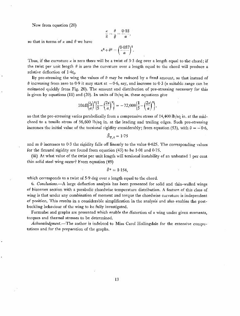
Now from equation (20)
so that in terms of K and 0 we have
K 0 0.18 ' a '
Thus, if the curvature K is zero there will be a twist of 3.3 deg over a length equal to the chord ; if the twist per unit length 0 is zero the curvature over a length equal to the chord will produce a relative deflection of 1.4t o.
By pre-stressing the wing the values of ~ may be reduced by a fixed amount, so that instead of increasing from zero to 0.9 it may start at -0 .6 , say, and increase to 0"3 (a suitable range can be
estimated quickly from Fig. 20). The amount and distribution of pre-stressing necessary for this is given by equations (11) and (20). In units of lb/sq in. these equations give
10OE(~)2{1-(~)~} = - 72,000{1- (~)2},
so that the pre-stressing varies parabolically from a compressive stress of 14,400 lb/sq in. at the mid-
chord to a tensile stress of 56,600 lb/sq in. at the leading and trailing edges. Such pre-stressing increases the initial value of the torsional rigidity considerably; from equation (53), with 0 = -0 .6 ,
ST,0 = 1.75
and as 0 increases to 0.3 the rigidity falls off linearly to the value 0.625. The corresponding values
for the flexural rigidity are found from equation (43) to be 1.01 and 0.75.
(iii) At what value of the twist per unit length will torsional instability of an unheated 1 per cent thin solid steel wing occur? From equation (49)
0* = 1.154,
which corresponds to a twist of 5-9 deg over a length equal to the chord.
6. Conclusions.--A large deflection analysis has been presented for solid and thin-walled wings of biconvex section with a parabolic chordwise temperature distribution. A feature of this class of wing is that under any combination of moment and torque the chordwise curvature is independent of position. This results in a considerable simplification in the analysis and also enables the post- buckling behaviour of the wing to be fully investigated.
Formulae and graphs are presented which enable the distortion of a wing under given moments, torques and thermal stresses to be determined.
Achnowledgment.--The author is indebted to Miss Carol Hollingdale for the extensive compu- tations and for the preparation of the graphs.
i
13

Ox, Oy
E, G
o~
a
t
h D
T
r0, r ,ar AT
E
w(x,y) w(x), w
M T K
0 K t
V A1, A~
?, a, ~, 0, 5I, ~, ~'
/z
Index * refers to critical
LIST OF SYMBOLS (See Fig. 1)
Cartesian axes,'Oy measured spanwise, Ox measured chordwise from the mid-chord of the wing Young's modulus, shear modulus (assumed constant) Poisson's ratio (assumed constant) Coefficient of thermal expansion (assumed constant) Wing chord Wing thickness Total thickness of spanwise stress-bearing material Skin thickness in thin-walled wing Flexural rigidity per unit width (assumed the same for spanwise and chordwise bending) Chordwise temperature distribution Defined by equation (10), in particular Difference between 'the average temperature of the leading and trailing edges' and the mid-chord temperature Spanwise middle-surface strain, measured from a stress-free datum Value of e when the wing is flat Defined by equation (4) Distorted middle surface of wing Chordwise variation of wing distortion defined by equation (1) Applied moment Applied torque Spanwise curvature Twist per unit length Chordwise durvature (constant for the class of wings considered) Strain energy per unit length due to middle-surface strains Strain energy per unit length due to flexure and torsion Total strain energy per unit length Constants Non-dimensional symbols defined by equation (20) or (21) Non-dimensional stiffnesses defined by equations (42) and (52) Defined by equation (41) M/T buckling conditions.
14

No. Author
1 H . L . Dryden and J. E. Duberg
2 L . F . Vosteen and K. E. Fuller
3 R . L . Bisplinghoff . . . .
4 NI J. Holt . . . . . .
5 B. Budiansky and J. Mayers . .
6 S .L . Kochanski and J. H. Argyris
7 E . H . Mansfield
8 S. Timoshenko
9 H. and B. S. Jeffreys
10 E . H . Mansfield ..
11 E . G . Broadbent . . . .
12 E . G . Broadbent . . . .
L I S T O F R E F E R E N C E S
Title, etc.
Aero-elastic effects of aerodynamic heating. Paper presented to 5th General Assembly, A.G.A.R.D., Ottawa,
Canada. June, 1955.
Behaviour of a cantilever plate under rapid-heating conditions. N.A.C.A. Research Memo. L.55E20c. July, 1955.
Some structural and aero-elastic considerations of high-speed flight. J. Ae. Sci. April, 1956.
Approximate analysis of the reduction in torsional rigidity and torsional buckling of solid wings under thermal stresses.
ft. Ae. Sci. June, 1956.
Influence of aerodynamic heating on the effective torsional stiffness of thin wings.
ft. Ae. Sci. December, 1956.
Some effects of kinetic heating on the stiffness of thin wings. Parts I and II.
Aircraft Engineering. October, 1957 and February, 1958.
The influence of aerodynamic heating on the flexural rigidity of a thin wing.
R. & M. 3115. September, 1957.
Theory of Plates and SheUs. McGraw-Hill. 1940.
Methods of Mathematical Physics. 2nd Edition. Cambridge. 1950.
The inextensional theory for thin flat plates. Quart. ft. Mech. App. Math. Vol. VIII . Pt 3. 1955.
Aero-elastic problems associated with high speed and high temperature.
ft. R. Ae. Soc. December, 1958.
Flutter of an untapered wing allowing for thermal effects. C.P. No. 442, April, 1959
15

PARABOLIC CHOROWISE. TEMPERATURE. DI%TRIIblJTION.
° i , ," / , . ' / / / / / / / / / / / / t t , ,
,,, ^ ~. K._ 8 ' Q.~" K. e r~' " ( 4 ¢ g ) ~ o
A ^
M 1 6 E ~
I F- o
t
NOTATION FOR.. SOLID WING.
V , g .
^ ^ ~,
t¢ e I¢' - ( 4 7 " @ ) ~ o
A ^
1 J k O
NOTATION FOR THIbt'tA/AL/E~ WIN~.
FIG. 1. Figure showing wing sections considered and notation.
16

FIG. 2. Variation of curvature ~ wi th torque T and mo men t ~ i (Tempera ture-s t ress parameter ~ = - 2).
,¢
6
FIG. 3. Variation of curvature ~ wi th torque T and m o m e n t 2t~ (Tempera ture-s t ress parameter d = - 1"43).
17

FIG. 4. Variation of curvature ~ with torque ~" and moment 1¢/(Temperature-stress parameter ~ = - 1).
\
Fro. 5. Variation of curvature g with torque ~ and momen t M (Temperature-stress parameter ~ = -0"5) .
18
/ / I -'7 ~ \ \ ! ,
-3
7 ' . I
^ .4 0 . 8
FIG. 6. Var ia t ion of curva ture g wi th to rque T and m o m e n t 2V/(Tempera ture -s t ress pa rame te r d = 0).
FIQ. 7. Var ia t ion of curva ture ~ wi th to rque 7 ~ and m o m e n t iV / (Tempera tu re - s t r e s s pa r ame te r d = 0"5).
19

3
-%
o
\
FIG. 8. Variation of curvature ~ with torque T and moment ~ / (Tempera tu r e - s t r e s s parameter 6 = 0"77).
/ i / ~ ,
- 3
0 . &
^
^
I .G
FIG. 9. Variation of curvature ~ with torque ~ and momen t ]¢ / (Tempera ture-s t ress parameter 8 = 1).
20
~= -0.4- 0 ' 4
e= -O& o'6 ~ = - i . z i.a ~ = - I ' G t ' 6
: - ~.0 e..O
FIc. 10. Variation of twist per uni t length /~ with torque T and moment ~ (Temperature-stress parameter d = - 2 ) .
FIG. 11.
@ = - 0 " 4 ~
i i
-Io -8 -E
/ / /
Variation of twist per uni t length ~ with torque T and m o m e n t ]~r (Temperature-s t ress parameter = - 1"43).
21

~ = -O.Zl. g=-a,8
~ = - ~..0
FIG. 12. Variation of twist per unit length t~ with torque ~" and moment 2Y/ (Temperature-stress parameter ~" = - 1 ) .
e : - O.4- ~-'-O'B g - - i . ~
6 : - 1,6 g=- a.O
e:O.4 6--O.8
~ : bG
FIG. 13. Variation of twist p e r unit length 0 with torque ~" and moment ~ / (Tempera ture-s t ress parameter 6 = - 0 . 5 ) .
2 2
~ : - 0.4-' ~ :0.~' ~ : - 0 ' 8 ~ : 0 . 8
FIG. 14. Variation o£ twist per unit length O with torque fi and moment ]~/ (Temperature-stress parameter = 0).
FIa. 1S. Variation of twist per unit length ~ with torque ~ and moment 2~/(Temperature-stress parameter = 0.5).
23

b=-
FIG. 16. Variation of twist per unit length 0 with torque T and moment ~/(Temperature-stress parameter = 0-77).
~=-0.4 ~=-o ~, ~=-v2. ~=-I.G ~=-~.'0
FIG. 17. Variation of twist per unit length ~ with torque T and moment ~/ (Temperature-stress parameter ~ = 1).
24

s , - I
~:b.s ~:o 8=-o.~ ~=~1 i~= - I
6= "&
FIG. 18. Regions in the 217/, fi plane in which ~ and ~ do not have unique values.
)MKN"T
RQUE ~V/',TUEK
qST/UNIT LENGTH
M~ERA'rU~E s'rR~ss
• (~o) O~(a,)
25
'L'

~o
1.5 /
v-
-0"66
/,
o 0 .5 l.O 1.5 ~.0 CURVATURE K,
FIG. 19. Bending moment-curvature relationships for various values of temperature-stress parame}er d.
4
5T, o
"~ S , f / " \ / \
~ , o ~ j f x ' ~-
-'+- -3 -~. -J 0 I ~ ~ 3 4
A A
FIG. 20. Initial values of the flexural and torsional rigidities SM, o and ,-?,'1',o (Variation with temperature-stress parameter d).
i
26

d- w
o
5"C
WHICH ALL THESE. CURVE.5 JOIN, 15 ALS0 THAT PREDICTE.[~ ~Y INEXTENSIONAL THEORY
4'0
3"0 /
!
0 i-'~' 0 0 .5 ].0 1.5 v..o
TWIST/UNIT LENGTH
FIG. i l . Torque-twist relationships for various values of temperature-stress parameter 6.
27

~o oo
4
T
3
,5/f
; Ml'r / /
Fie . 22. Variation of twist per uni t length 0 wi th to rque 2# (Temperature-stress parameter d = 0).
/
/ / , / f / /
. / f INEXTENSIONA, L / THF_.OIL~
g a 3
Fro. 23. Variation of twist per uni t length 0 with torque 2# (Temperature-stress parameter d = 0'5).
S
~ ~ ~E'EXTE'yNSIONAL.
o a 3 ~ A FIo. 24. Va r i a t i on o f l o n g i t u d i n a l cu rva tu re ~ w i t h m o m e n t M
(Tempera tu re -s t ress pa ramete r ~ = 0).
~:Q'5 : M/T
M
I / r . / -
0 0 a ~ 4 S
FIG. 25. Variation of longitudinal curvature ~ with m o m e n t ~ / (Temperature-s t ress parameter c5 = 0"5).
J

4.
t 0
'J / / J ~ ° o I ~ ~ = MIT
~ : '~
f f
IN~XT~.NSIONA~ THEORY
FiG. 26. Variation of ehordwise curvature k' with m o m e n t d~/ (Temperature-stress parameter 8 = 0).
S
i ~-'O.B
: M/T /
I:
;/
/
IN ~- XTE.N .~IQNA, I-
TH~'ORY.
FIO. 27. Variation of chordwise curvature ~' with m o m e n t (Temperature-stress parameter ~ = 0'5).
Wt. 66 K.5.
29
Printed in England under the authority of Her Majesty's Stationery Office by John Wright & Sons Ltd. at the Stonebridge Press, Bristol

III / / a=o
- O ~ ~' ~ 3
FIo. 26. Variation of chordwise curvature #" with moment
(Temperature-stress parameter i} -- 0).
-I fjJ
0
Fro . 27. Var ia t ion of cho rdwise c u r v a t u r e ~" w i t h m o m e n t
( T e m p e r a t u r e - s t r e s s p a r a m e t e r ~ = 0.5).
Wt. 66 K.5.
29
Printed in England under the authority of Her Majesty's Stationery Office byJohn Wright ~ Sons Ltd. at the Stonebridge Press, Bristol

Publications of the Aeronautical Research Council
1941 Aero and
1942 Vol. I. Vol.
1943 Vol. Vol.
1944 Vol. Vol.
1945 Vol. Vol. Vol.
Vol.
1946 Vol. Vol.
Vol.
I947 Vol. Vol.
A N N U A L T E C H N I C A L R E P O R T S OF T H E A E R O N A U T I C A L R E S E A R C H C O U N C I L ( B O U N D V O L U M E S )
Hydrodynamics, Aerofoils, Airscrews, Engines, Flutter, Stability and Control, Structures. 63 s. (post 2s. 3d.)
Aero and Hydrodynamics, Aerofoils, Airscrews, Engines. 75s. (post 2s. 3d.) II. Noise, Parachutes, Stability and Control, Structures, Vibration, Wind Tunnels. 47s. 6d. (post Is. 9d.)
I. Aerodynamics, Aerofoils, Airserews. 8os. (post 2s.) II. Engines, Flutter, Materials, Parachutes, Performance, Stability and Control, Structures.
9os. (post 2s. 3d.) I. Aero and Hydrodynamics, Aerofoils, Aircraft, Airserews, Controls. 84s. (post 2s. 6d.)
II. Flutter and Vibration, Materials, Miscellaneous, Navigation, Parachutes, Performance, Plates and Panels, Stability, Structures, Test Equipment, Wind Tunnels. 84s. (post 2s. 6d.)
I. Aero and Hydrodynamics, Aerofoils. I3OS. (post 3s.) II. Aircraft, Airscrews, Controls. i3os. (post 3s.)
III . Flutter and Vibration, Instruments, Miscellaneous, Parachutes, Plates and Panels, Propulsion. 13os. (post 2s. 9d.)
IV. Stability, Structures, Wind Tunnels, Wind T u n n d Technique. I3os. (post 2s. 9d.)
I. Accidents, Aerodynamics, Aerofoils and Hydrofoils. I68s. (post 3s. 3d.) II. Airscrews, Cabin Cooling, Chemical Hazards, Controls, Flames, Flutter, Helicopters, Instruments and
Instrumentation, Interference, Jets, Miscellaneous, Parachutes. I68S. (post 2s. 9d.) III . Performance, Propulsion, Seaplanes, Stability, Structures, Wind Tunnels. 168s. (post 3s. 6d.)
I. Aerodynamics, Aerofoils, Aircraft. 168s. (post 3s. 3d.) II. Airscrews and Rotors, Controls, Flutter, Materials, Miscellaneous, Parachutes, Propulsion, Seaplanes,
Stability, Structures, Take-off and Landing. 168s. (post 3s. 3d.)
Special Vol.
Vol.
Vol.
Volumes I. Aero and Hydrodynamics, Aerofoils, Controls, Flutter, Kites, Parachutes, Performance, Propulsion,
Stability. 126s. (post 2s. 6d.) II . Aero and Hydrodynamics, Aerofoils, Airscrews, Controls, Flutter, Materials, Miscellaneous, Parachutes,
Propulsion, Stability, Structures. 147s. (post 2s. 6d.) I IL Aero and Hydrodynamics, Aerofoils, Airscrews, Controls, Flutter, Kites, Misedlaneous, Parachutes,
Propulsion, Seaplanes, Stability, Structures, Test Equipment. I89s. (post 3s. 3d.)
Reviews of the Aeronautical Research Council 1939-48 3s- (post 5d.) 1949-54 5s. (post 5d.)
Index to all Reports and Memoranda published in the Annual Technical Reports I9O9-47 R. & M. 2600 6s. (post 2d.)
Indexes to the Reports and Memoranda of the Aeronautical Research Council Between Nos. 2351-2449 R. & M. No. 2450 2s. (post 2d.) Between Nos. 2451-2549 R. & M. No. 255 ° 2s. 6d. (post 2d.) Between Nos. 2551-2649 R. & M. No. 2650 2s. 6d. (post 2d.) Between Nos. 2651-2749 R. & M. No. 2750 2s. 6d. (post 2d.) Between Nos. 2751--2849 R. & M. No. 2850 2s. 6d. (post 2d.) Between Nos. 2851--2949 R. & M. No. 295 ° 3s. (post 2d.)
HER MAJESTY'S S T A T I O N E R Y O F F I C E from the addresses overleaf

R. & M. No. 3195
~) Crown copyright x96x
Published by HER ~/~AJESTY'S STATIONERY OFFICE
To be purchased from York House, Kingsway, London w.c.2
423 Oxford Street, London w.x X3A Castle Street, Edinburgh 2
Io9 St. Mary Street, Cardiff 39 King Street, Manchester 2
50 Fairfax Street, Bristol x 2 Edmund Street, Birmingham 3
80 Chichester Street, Belfast i or through any bookseller
R. & M. No. 3195
S.O. Code No. 23-3x95