Embed Size (px)
Citation preview

COMBINATION SANDERMODEL G1014Z
INSTRUCTION MANUAL
COPYRIGHT © 1992 BY GRIZZLY INDUSTRIAL, INC. REG.# TX 3 360 514WARNING: NO PORTION OF THIS MANUAL MAY BE REPRODUCED IN ANY SHAPE
OR FORM WITHOUT THE WRITTEN APPROVAL OF GRIZZLY INDUSTRIAL, INC.REVISED APRIL, 1997. PRINTED IN USA


G1014Z Combination Sander -1-
Table Of ContentsPAGE
1. SAFETY ....................................................................................................................2SAFETY RULES FOR ALL TOOLS ....................................................................2ADDITIONAL SAFETY INSTRUCTIONS FOR SANDERS..................................3
2. CIRCUIT REQUIREMENTS...................................................................................... 4110V OPERATION ..............................................................................................4GROUNDING ......................................................................................................4
3. GENERAL INFORMATION ...................................................................................... 5UNPACKING ........................................................................................................6PIECE INVENTORY ............................................................................................6CLEAN UP............................................................................................................7SITE CONSIDERATIONS ....................................................................................7
4. ASSEMBLY ..........................................................................................................8ORDER OF ASSEMBLY ................................................................................8STAND ........................................................................................................8-9SANDING UNIT........................................................................................10-11
5. ADJUSTMENTS ................................................................................................12BELT REPLACEMENT..................................................................................12BELT TRACKING ..........................................................................................12BELT TENSIONING ......................................................................................13VERTICAL POSITIONING ............................................................................14CHANGING DISCS ......................................................................................15TABLE TILT ..................................................................................................15
6. OPERATIONS ....................................................................................................16TEST RUN ....................................................................................................16HORIZONTAL SANDING ..............................................................................16CURVED SANDING ......................................................................................17DISC SANDING ............................................................................................17
7. MAINTENANCE..................................................................................................18LUBRICATION ..............................................................................................18V-BELT ........................................................................................................18TABLE ..........................................................................................................18GENERAL......................................................................................................18
8. CLOSURE ..........................................................................................................19MACHINE DATA ..........................................................................................20PART BREAKDOWNS ............................................................................21-23PART LIST ....................................................................................................24WARRANTY AND RETURNS ......................................................................25

-2- G1014Z Combination Sander
WARNING: For Your Own Safety ReadInstruction Manual Before Operating Sander
Safety Instructions For Power ToolsThese safety rules cannot cover every situation in a work shop. Consider your conditions when setting upor operating your jointer.
SECTION 1: SAFETY
a) Always wear eye protection.
b) When belt sanding, support the workpiecewith a miter gauge, backstop or the work-table.
c) When disc sanding, support the workpieceon the worktable.
f) Maintain 1⁄16'' maximum clearance betweenthe work table and the sanding belt or disc.
9. USE PROPER EXTENSION CORD. Makesure your extension cord is in good condi-tion. When using an extension cord, be sureit is rated Hard Service (grade S) or better.Conductor size must be 16 A.W.G. for cordsup to 100 feet in length. An undersized cordwill cause a drop in line voltage resulting inloss of power and overheating. Your exten-sion cord must also contain a ground wireand plug pin. Always repair or replaceextension cords if they become damaged.Minimum Gage for extension cord:
16 A.W.G. 50ft16 A.W.G. 100ft14 A.W.G. 200ft12 A.W.G. 300ft
10. WEAR PROPER APPAREL Do not wearloose clothing, gloves, neckties, rings,bracelets, or other jewelry which may getcaught in moving parts. Non-slip footwear isrecommended. Wear protective hair coveringto contain long hair.
11. ALWAYS USE SAFETY GLASSES. Alsouse face or dust mask if cutting operation isdusty. Everyday eyeglasses only haveimpact resistant lenses, they are NOT safetyglasses.
1. KEEP GUARDS IN PLACE and in workingorder.
2. REMOVE ADJUSTING KEYS ANDWRENCHES. Form habit of checking to seethat keys and adjusting wrenches areremoved from tool before turning on.
3. KEEP WORK AREA CLEAN. Clutteredareas and benches invite accidents.
4. DON’T USE IN DANGEROUS ENVIRON-MENT. Don’t use power tools in damp orwet locations, or expose them to rain. Keepwork area well lighted.
5. KEEP CHILDREN AWAY. All visitorsshould be kept a safe distance from workarea.
6. MAKE WORK SHOP KID PROOF withpadlocks, master switches, or by removingstarter keys.
7. DON’T FORCE TOOL. It will do the job bet-ter and safer at the rate for which it wasdesigned.
8. USE RIGHT TOOL. Don’t force tool orattachment to do a job for which it was notdesigned.

G1014Z Combination Sander -3-
Additional Safety Instructions For Sanders
17. USE RECOMMENDED ACCESSORIES.Consult the owner’s manual for recommend-ed accessories. The use of improper acces-sories may cause risk of injury to persons.
18. CHECK DAMAGED PARTS. Before furtheruse of the tool, a guard or other part that isdamaged should be carefully checked todetermine that it will operate properly andperform its intended function - check for align-ment of moving parts, binding of movingparts, breakage of parts, mounting, and anyother conditions that may affect its operation.A guard or other part that is damaged shouldbe properly repaired or replaced.
19. DIRECTION OF FEED. Feed work into ablade or cutter against the direction of rota-tion of the blade or cutter only.
20. NEVER LEAVE TOOL RUNNING UNAT-TENDED. TURN POWER OFF. Don’t leavetool until it comes to a complete stop.
6. If there is any doubt as to the stability orintegrity of the material to be sanded, don’tsand it.
7. Do not operate sander with a damaged orbadly worn disc or belt.
8. When disc sanding, feed material into theportion of the disc spinning down toward thetable.
9. Habits — good or bad — are hard to break.Develop good habits and safety will becomesecond nature to you.
1. Be aware of belt or disc rotation when sand-ing.
2. Keep fingertips away from the moving belt ordisc.
3. Never use excessive force when sanding.Doing this greatly increases the chances ofpersonal injury and motor overload.
4. Always feed the work against the direction ofrotation
5. Even if you have a reliable method of dustcollection, use a dust mask or respiratorwhen sanding, as well as eye and ear pro-tection.
12. SECURE WORK. Use clamps or a vise tohold work when practical. It’s safer thanusing your hand and frees both hands tooperate tool.
13. DON’T OVERREACH. Keep proper footingand balance at all times.
14. MAINTAIN TOOLS WITH CARE. Keep toolssharp and clean for best and safest perfor-mance. Follow instructions for lubricating andchanging accessories.
15. DISCONNECT TOOLS before servicing andchanging accessories, such as blades, bits,cutters, and the like.
16. REDUCE THE RISK OF UNINTENTIONALSTARTING. Make sure switch is in off posi-tion before plugging in.
-4- G1014Z Combination Sander
Figure 1.
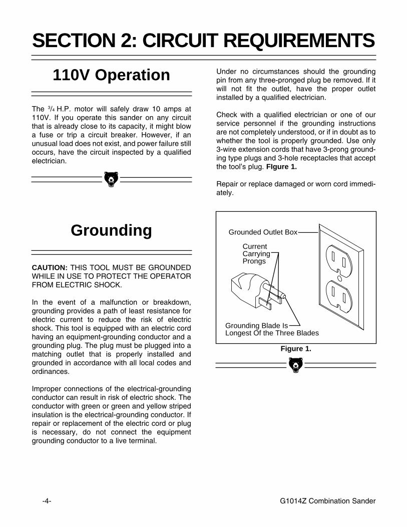
Grounded Outlet Box
CurrentCarryingProngs
Grounding Blade IsLongest Of the Three Blades
Under no circumstances should the groundingpin from any three-pronged plug be removed. If itwill not fit the outlet, have the proper outletinstalled by a qualified electrician.
Check with a qualified electrician or one of ourservice personnel if the grounding instructionsare not completely understood, or if in doubt as towhether the tool is properly grounded. Use only3-wire extension cords that have 3-prong ground-ing type plugs and 3-hole receptacles that acceptthe tool’s plug. FIgure 1.
Repair or replace damaged or worn cord immedi-ately.
110V Operation
The 3/4 H.P. motor will safely draw 10 amps at110V. If you operate this sander on any circuitthat is already close to its capacity, it might blowa fuse or trip a circuit breaker. However, if anunusual load does not exist, and power failure stilloccurs, have the circuit inspected by a qualifiedelectrician.
Grounding
CAUTION: THIS TOOL MUST BE GROUNDEDWHILE IN USE TO PROTECT THE OPERATORFROM ELECTRIC SHOCK.
In the event of a malfunction or breakdown,grounding provides a path of least resistance forelectric current to reduce the risk of electricshock. This tool is equipped with an electric cordhaving an equipment-grounding conductor and agrounding plug. The plug must be plugged into amatching outlet that is properly installed andgrounded in accordance with all local codes andordinances.
Improper connections of the electrical-groundingconductor can result in risk of electric shock. Theconductor with green or green and yellow stripedinsulation is the electrical-grounding conductor. Ifrepair or replacement of the electric cord or plugis necessary, do not connect the equipmentgrounding conductor to a live terminal.
SECTION 2: CIRCUIT REQUIREMENTS

G1014Z Combination Sander -5-
We are proud to bring you the Model G1014ZCombination Sander. The Model G1014Z is partof a growing Grizzly family of fine woodworkingmachinery. When used according to the guide-lines set forth in this manual, you can expectyears of trouble-free, enjoyable operation andproof of Grizzly’s commitment to customer satis-faction.
The Model G1014Z is a combination 6" x 48" beltand 9" disc sander that is capable of a wide vari-ety of operations. The 6" wide belt enables you tosand large areas flat very quickly, and the 9" discand table allow sanding at many different angles.The G1014Z comes complete with stand, mitergauge, motor and electrical package.
We are also pleased to provide this instructionmanual with the Model G1014Z CombinationSander. This instruction manual was written toguide you through assembly, review safety con-siderations and cover general operating proce-dures. It represents our latest effort to producethe best documentation possible. If you have anyconstructive criticisms or comments that you feelwe should include in our next printing, pleasewrite to us at the Bellingham, WA address at theend of this section.
SECTION 3: GENERAL INFORMATIONMost important, we stand behind our machines.We have two excellent regional service depart-ments at your disposal should the need arise. Ifyou have any service questions or parts requests,please call or write to us at the location listedbelow.
Grizzly Industrial, Inc.1203 Lycoming Mall Circle
Muncy, PA 17756Phone:(570) 546-9663
Fax:(800) 438-5901E-Mail: [email protected] Site: http://www.grizzly.com
To comment on this manual write to:
Grizzly Industrial, Inc.C⁄O Technical Documentation
P.O. Box 2069Bellingham, WA 98227
To operate this, or any other power tool safelyand efficiently, it is essential to become as famil-iar with it as possible. The time you invest beforeyou begin to use your Model G1014Z will be timewell spent. DO NOT operate this machine untilyou are familiar with the contents of this manual.

-6- G1014Z Combination Sander
Contents of the Bolt Bag
QTY. DESCRIPTION LOCATION16 5⁄16''-18 x 1⁄2'' Carriage Bolts Stand16 5⁄16'' Flat Washers Stand16 5⁄16''-18 Hex Nuts Stand4 5⁄16''-18 x 1⁄2'' Hex Bolts Stand/Base4 5⁄16'' Flat Washers Stand/Base4 5⁄16''-18 x 1'' Hex Bolts Stand /Feet8 5⁄16'' Flat Washers Stand /Feet4 5⁄16''-18 Hex Nuts Stand /Feet
In the event that any non-proprietary parts aremissing (e.g. a nut or a washer...), we would beglad to replace them, or, for the sake of expedi-ency, replacements can be obtained at your localhardware store.
Unpacking
The Model G1014Z Sander is shipped from themanufacturer in a carefully packed carton. If youdiscover the machine is damaged after you’vesigned for delivery, please call our CustomerService number immediately for advice.
Save the containers and all packing materials forpossible inspection by the carrier or its agent.Otherwise filing a freight claim can be difficult.
Caution: The G1014Z is a heavy machine (120lbs. shipping weight). DO NOT over-exert your-self while unpacking or moving your machine –get assistance. In the event that your Sandermust be moved up or down a flight of stairs, besure that the stairs are capable of supporting thecombined weight of people and the machine.
When you are completely satisfied with the con-dition of your shipment, you should inventory itsparts.
Piece Inventory
After all the parts have been removed from thecontainer, you should have:
1 Sanding Unit1 Sanding Belt 1 Sanding Disc1 Cast Iron Disc1 Idler Roller1 Back Stop 1 Miter Gauge1 Work Table1 Table Support Rod4 Stand Legs4 Upper Stand Braces2 Lower Stand Braces4 Rubber Feet 1 Quick Release Handle1 Dust Port 1 Idler Roller Guard1 Bolt Bag

G1014Z Combination Sander -7-
Clean up
The work table and other unpainted parts of theModel G1014Z are coated with a waxy oil thatprotects them from corrosion during shipment.Remove the protective coating with mineral spir-its and cloth rags. Do not use gasoline or otherpetroleum based solvents because of theirextremely low flash points. Do not use chlorine-based solvents – if you happen to splash someonto a painted surface, you’ll ruin the finish.
WARNING!
Follow the safety rules listed below whenworking with solvents:
1. Read and follow all directions and warningson the solvent label.
2. Work only in a well ventilated area.
3. Do not work near any type of open flame(e.g., pilot lights, kerosene heaters, and soon).
4. DO NOT smoke while working with flamma-ble material.
5. Paper towels and rags from the cleaningprocess are extremely combustible. Disposeof waste towels so they do not create a firehazard.
Site Considerations
1. Floor Load: Your G1014Z Sander repre-sents a medium weight load in a small foot-print. Most commercial floors are suitable forthe Model G1014Z. Some residential floorsmay require additional build up to supportboth machine and operator.
2. Working Clearances: Consider existing andanticipated needs, size of material to beprocessed through each machine, andspace for auxiliary stands, work tables orother machinery when establishing a loca-tion for your sander.
3. Lighting and Outlets: Lighting should bebright enough to eliminate shadow and pre-vent eye strain. Electrical circuits should bededicated or large enough to handle amper-age requirements. Outlets should be locatednear each machine so power or extensioncords are clear of high-traffic areas. Observelocal electrical codes for proper installationof new lighting, outlets, or circuits.

-8- G1014Z Combination Sander
Order Of Assembly
SECTION 4: ASSEMBLY
Most of your Combination Sander has beenassembled at the factory. The few remainingpieces will go together quickly and should bedone in the following order:
1. Stand2. Mounting Sanding Unit3. Attaching the Back Stop4. Attaching Sanding Disc5. Mounting the Work Table
Note: All die-cut metal parts have a sharp edge(called “flashing”) on them after they are formed.This is removed at the factory. Sometimes,though, a bit of flashing might escape inspection.Please examine the edges of all die-cut metalparts before handling them.
TOOLS REQUIRED: Only a few common toolsare required to assemble your CombinationSander. Specifically, these are: 6" adjustablewrench, 12mm open end wrench, regular screw-driver, Phillips screwdriver, and a 4mm Allenwrench.
Stand
The G1014Z Combination Sander stand is anopen frame style. The four legs are connectedwith top and bottom cross braces.
1. Attach Rubber Feet to base using the four5⁄16''-18 x 1'' Hex bolts, Hex Nuts and FlatWashers provided. Figure 2.
Figure 2.
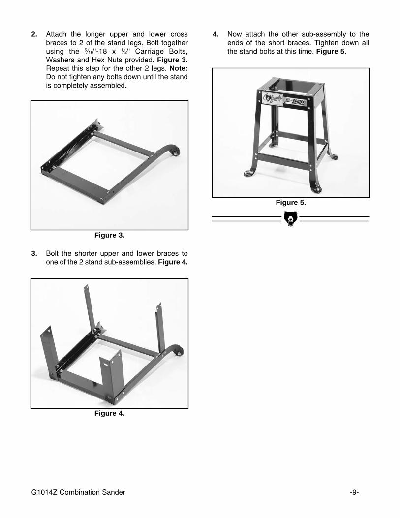
Figure 3.
G1014Z Combination Sander -9-
Figure 4.
3. Bolt the shorter upper and lower braces toone of the 2 stand sub-assemblies. Figure 4.
4. Now attach the other sub-assembly to theends of the short braces. Tighten down allthe stand bolts at this time. Figure 5.
Figure 5.
2. Attach the longer upper and lower crossbraces to 2 of the stand legs. Bolt togetherusing the 5⁄16''-18 x 1⁄2'' Carriage Bolts,Washers and Hex Nuts provided. Figure 3.Repeat this step for the other 2 legs. Note:Do not tighten any bolts down until the standis completely assembled.
-10- G1014Z Combination Sander
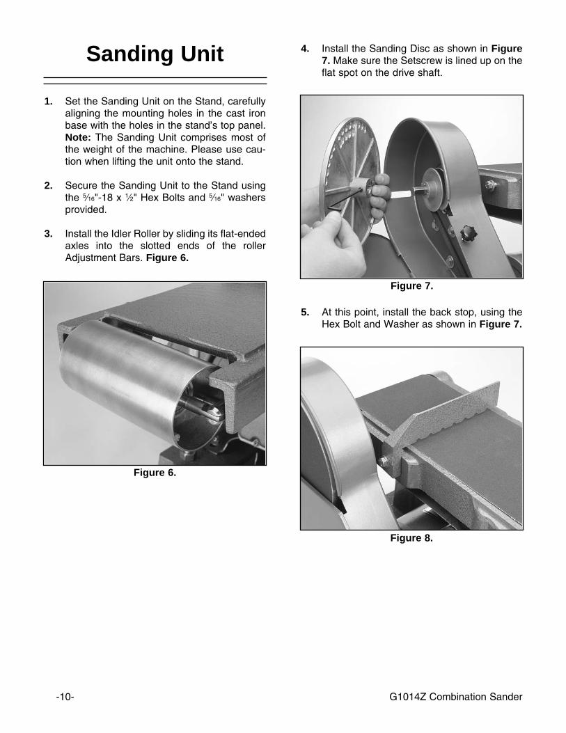
Figure 7.
5. At this point, install the back stop, using theHex Bolt and Washer as shown in Figure 7.
Figure 8.
4. Install the Sanding Disc as shown in Figure7. Make sure the Setscrew is lined up on theflat spot on the drive shaft.
Figure 6.
Sanding Unit
1. Set the Sanding Unit on the Stand, carefullyaligning the mounting holes in the cast ironbase with the holes in the stand’s top panel.Note: The Sanding Unit comprises most ofthe weight of the machine. Please use cau-tion when lifting the unit onto the stand.
2. Secure the Sanding Unit to the Stand usingthe 5⁄16"-18 x 1⁄2" Hex Bolts and 5⁄16" washersprovided.
3. Install the Idler Roller by sliding its flat-endedaxles into the slotted ends of the rollerAdjustment Bars. Figure 6.
G1014Z Combination Sander -11-
Figure 9.
Figure 10.
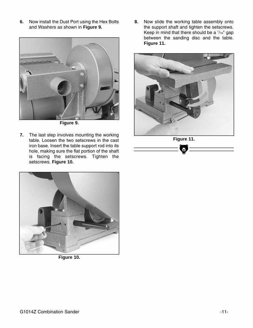
6. Now install the Dust Port using the Hex Boltsand Washers as shown in Figure 9.
7. The last step involves mounting the workingtable. Loosen the two setscrews in the castiron base. Insert the table support rod into itshole, making sure the flat portion of the shaftis facing the setscrews. Tighten thesetscrews. Figure 10.
8. Now slide the working table assembly ontothe support shaft and tighten the setscrews.Keep in mind that there should be a 1/16" gapbetween the sanding disc and the table.Figure 11.
Figure 11.

-12- G1014Z Combination Sander
2. Turn the knob approximately 1⁄4 turn clock-wise to move the belt towards the trackingknob, counter-clockwise to move the beltaway.
3. Turn the machine on and off again quickly tosee if the tracking has improved. If not,repeat step 1. If tracking is improved moveto step 4.
4. Now with the sander running, adjust theknob to fine tune the belt tracking.
Belt Replacement
SECTION 5: ADJUSTMENTS
With the exception of Belt Tracking, adjustmentsto your Combination Sander should be made withthe power off and the machine unplugged.
Unlock the Quick-Release Lever by pulling thelever straight out. Figure 12. Slide the belt off therollers straight toward you. Reverse this processto install a new belt.
Figure 12.
Belt Tracking
The goal of this procedure is to achieve properbelt tracking that prevents the belt from wander-ing off to either side.
1. To adjust the tracking, quickly turn thesander on and off. Observe the belt’s behav-ior. If the belt moves to one side or the other,you will need to adjust the tracking knob.Figure 13.
Figure 13.
G1014Z Combination Sander -13-
3. Tighten hex bolt, PN # 91 and run the sanderto adjust the tracking if necessary.
4. Try aggressively sanding a piece of scrapwood. If the tracking is not significantlyaffected and the belt does not slip on thedrum, your belt tension is correct.
Belt Tensioning
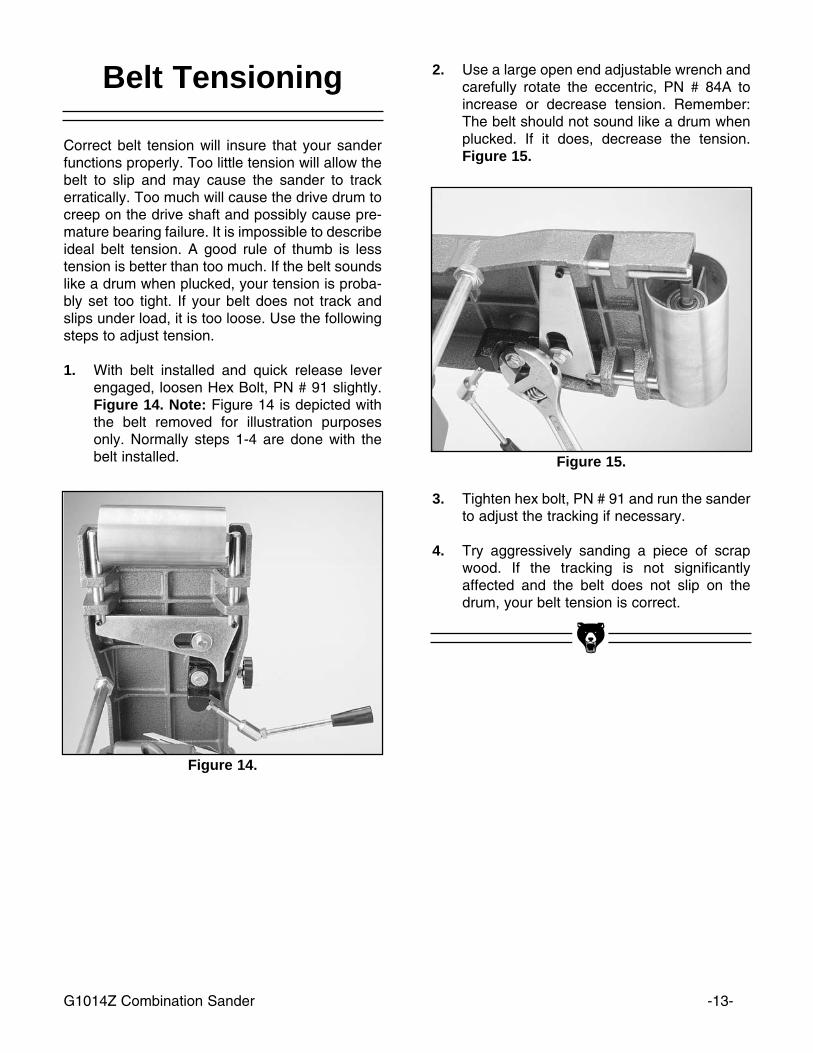
Correct belt tension will insure that your sanderfunctions properly. Too little tension will allow thebelt to slip and may cause the sander to trackerratically. Too much will cause the drive drum tocreep on the drive shaft and possibly cause pre-mature bearing failure. It is impossible to describeideal belt tension. A good rule of thumb is lesstension is better than too much. If the belt soundslike a drum when plucked, your tension is proba-bly set too tight. If your belt does not track andslips under load, it is too loose. Use the followingsteps to adjust tension.
1. With belt installed and quick release leverengaged, loosen Hex Bolt, PN # 91 slightly.Figure 14. Note: Figure 14 is depicted withthe belt removed for illustration purposesonly. Normally steps 1-4 are done with thebelt installed.
Figure 14.
2. Use a large open end adjustable wrench andcarefully rotate the eccentric, PN # 84A toincrease or decrease tension. Remember:The belt should not sound like a drum whenplucked. If it does, decrease the tension.Figure 15.
Figure 15.
-14- G1014Z Combination Sander
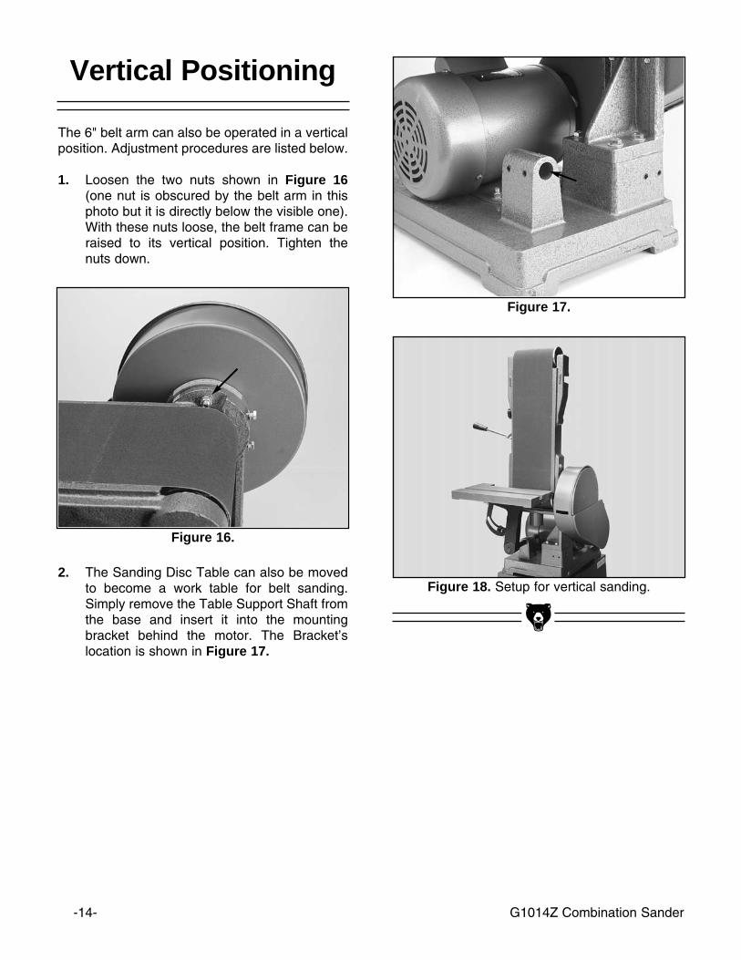
Figure 18. Setup for vertical sanding.2. The Sanding Disc Table can also be moved
to become a work table for belt sanding.Simply remove the Table Support Shaft fromthe base and insert it into the mountingbracket behind the motor. The Bracket’slocation is shown in Figure 17.
Vertical Positioning
The 6" belt arm can also be operated in a verticalposition. Adjustment procedures are listed below.
1. Loosen the two nuts shown in Figure 16(one nut is obscured by the belt arm in thisphoto but it is directly below the visible one).With these nuts loose, the belt frame can beraised to its vertical position. Tighten thenuts down.
Figure 16.
Figure 17.
G1014Z Combination Sander -15-
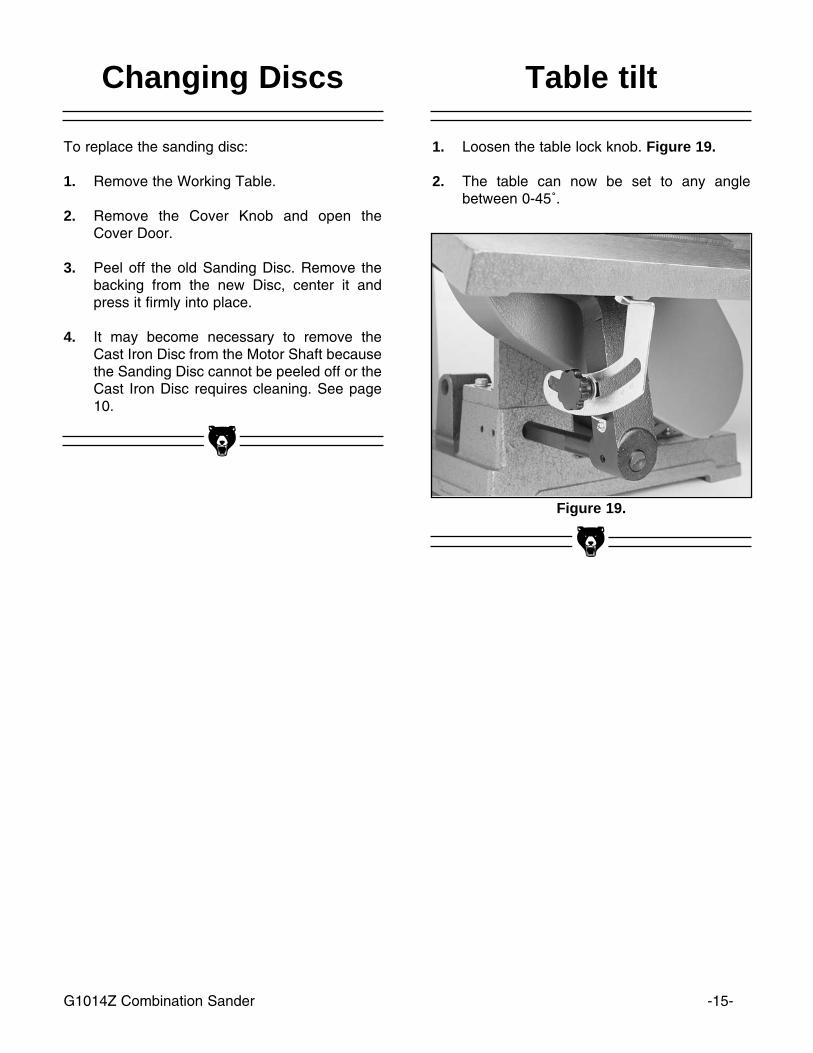
Figure 19.
Changing Discs
To replace the sanding disc:
1. Remove the Working Table.
2. Remove the Cover Knob and open theCover Door.
3. Peel off the old Sanding Disc. Remove thebacking from the new Disc, center it andpress it firmly into place.
4. It may become necessary to remove theCast Iron Disc from the Motor Shaft becausethe Sanding Disc cannot be peeled off or theCast Iron Disc requires cleaning. See page10.
Table tilt
1. Loosen the table lock knob. Figure 19.
2. The table can now be set to any anglebetween 0-45˚.
-16- G1014Z Combination Sander
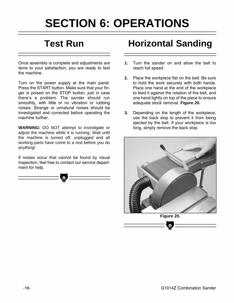
Horizontal Sanding
1. Turn the sander on and allow the belt toreach full speed.
2. Place the workpiece flat on the belt. Be sureto hold the work securely with both hands.Place one hand at the end of the workpieceto feed it against the rotation of the belt, andone hand lightly on top of the piece to ensureadequate stock removal. Figure 20.
3. Depending on the length of the workpiece,use the back stop to prevent it from beingejected by the belt. If your workpiece is toolong, simply remove the back stop.
Figure 20.
SECTION 6: OPERATIONS
Once assembly is complete and adjustments aredone to your satisfaction, you are ready to testthe machine.
Turn on the power supply at the main panel.Press the START button. Make sure that your fin-ger is poised on the STOP button, just in casethere’s a problem. The sander should runsmoothly, with little or no vibration or rubbingnoises. Strange or unnatural noises should beinvestigated and corrected before operating themachine further.
WARNING: DO NOT attempt to investigate oradjust the machine while it is running. Wait untilthe machine is turned off, unplugged and allworking parts have come to a rest before you doanything!
If noises occur that cannot be found by visualinspection, feel free to contact our service depart-ment for help.
Test Run

G1014Z Combination Sander -17-
Curved Sanding
To sand curves, use the end of the belt arm. Holdthe workpiece firmly and apply light, even pres-sure to the belt. To avoid excessive loading of thebelt in one area, move workpiece slowly acrossentire surface of belt. Figure 21.
Figure 21.
Disc Sanding
1. Loosen table lock knob and tilt work table todesired angle. Tighten lock knob.
2. Ease workpiece into the half of the disc thatspins down toward the table. Figure 22.
3. When using the table for beveled sandingoperations, smaller workpieces are at risk ofgetting jammed between the disc (or verticalbelt) and the table. Figure 23.
Figure 22.
Figure 23.
-18- G1014Z Combination Sander
SECTION 7: MAINTENANCE
Lubrication
V- Belt
Your combination sander is equipped with shield-ed and pre-lubricated ball bearings and requireno lubrication for the life of the bearings. All bear-ings are common sizes and are readily availablefrom a local bearing supply house or our ServiceDepartment.
Without proper belt tension and correct pulleyalignment, your sander will vibrate excessivelyand wear out the V-belt and the bearings muchfaster than normal. The pulleys can be aligned byplacing a straightedge along the outside flangesand sighting down the straightedge. Move onepulley along the shaft until both pulleys are in line.Proper belt tension can be checked by squeezingthe midpoint of the belt with moderate pressure(about 5 pounds). The resulting deflection shouldbe about 1/4". If it isn’t, it will be necessary toloosen the motor mount bolts and slide the motorto either add or subtract tension from the belt.
Make a habit of inspecting your sander each timeyou use it. Check for the following conditions andrepair or replace when necessary.
1. Loose mounting bolts.
2. Worn switch.
3. Worn or damaged cords and plugs.
4. Worn or damaged V-belt.
5. Poor belt tensioning/tracking.
General
Table
The working table and other non-painted sur-faces on the Model G1014Z should be protectedagainst rust and pitting. Wiping the sander cleanafter every use ensures that sawdust isn’tallowed to trap moisture against bare metal sur-faces.
Some woodworkers recommend using automo-tive paste wax on exposed steel and cast ironsurfaces. The wax provides a layer of protection,as well as reducing friction between lumber andthe table. Avoid waxes that contain silicone orother synthetic ingredients. These materials canfind their way into lumber that’s being sanded andcan make staining and finishing difficult. If youuse paste wax, make sure that it’s 100%Carnauba wax.

G1014Z Combination Sander -19-
The following pages contain general machinespecifications, parts diagram and list andWarranty/Return information for your ModelG1014Z Combination Sander.
If you need parts or help in assembling yourmachine, or if you need operational information,we encourage you to call our ServiceDepartment. Our trained service technicians willbe glad to help you.
If you have comments or concerns dealing specif-ically with this manual, please write to ourBellingham, Washington location using theaddress in the Introduction. The specifications,drawings, and photographs illustrated in thismanual represent the Model G1014Z as suppliedwhen the manual was prepared. However, due toGrizzly’s policy of continuous improvement,changes may be made at any time with no oblig-ation on the part of Grizzly. Whenever possible,though, we send manual updates to all owners ofa particular tool or machine. Should you receiveone, add the new information to this manual andkeep it for reference.
The information in this manual has been obtainedfrom sources we believe to be reliable and as up-to-date as possible. We have included someimportant safety measures which are essential tothis machine’s operation. While most safety mea-sures are generally universal, Grizzly remindsyou that each workshop is different and safetyrules should be considered as they apply to yourspecific situation.
We recommend you keep a copy of our currentcatalog for complete information regardingGrizzly's warranty and return policy. If you needadditional technical information relating to thismachine, or if you need general assistance orreplacement parts, please contact the ServiceDepartment listed in the introduction.
Additional information sources are necessary torealize the full potential of this machine. Tradejournals, woodworking magazines, and your locallibrary are good places to start.
WARNING!Like all power tools, there is danger associatedwith the Model G1014Z Combination Sander.Use the tool with respect and caution to lessenthe possibility of mechanical damage or operatorinjury. If normal safety precautions are over-looked or ignored, injury to the operator or othersin the area is likely.
The Model G1014Z was specifically designed forsanding operations. DO NOT MODIFY AND/ORUSE THIS SANDER FOR ANY OTHER PUR-POSE. Modifications or improper use of thistool will void the warranty. If you are confusedabout any aspect of this machine, DO NOT use ituntil all your questions have been answered.
SECTION 8: CLOSURE
-20- G1014Z Combination Sander
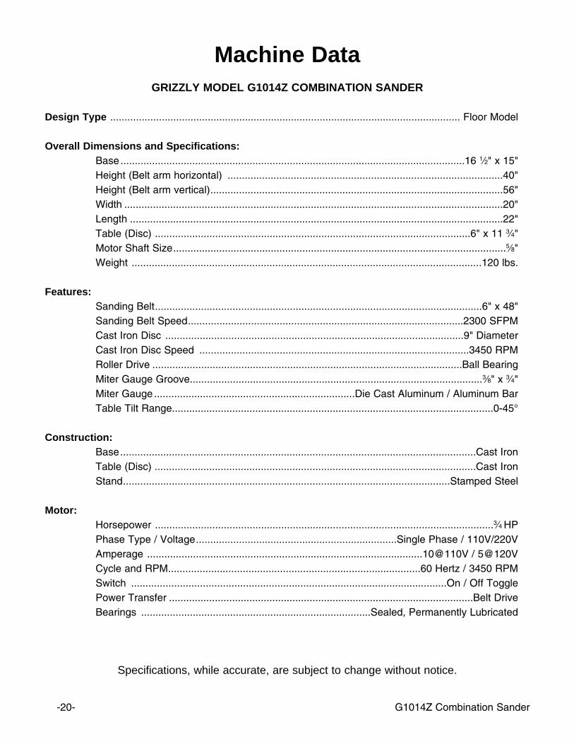
Machine DataGRIZZLY MODEL G1014Z COMBINATION SANDER
Design Type .......................................................................................................................... Floor Model
Overall Dimensions and Specifications:Base........................................................................................................................16 1⁄2" x 15"Height (Belt arm horizontal) ................................................................................................40" Height (Belt arm vertical)......................................................................................................56" Width ....................................................................................................................................20" Length ..................................................................................................................................22" Table (Disc) ..............................................................................................................6" x 11 3⁄4" Motor Shaft Size....................................................................................................................5⁄8"Weight ..........................................................................................................................120 lbs.
Features:Sanding Belt..................................................................................................................6" x 48"Sanding Belt Speed................................................................................................2300 SFPM Cast Iron Disc ........................................................................................................9" Diameter Cast Iron Disc Speed ..............................................................................................3450 RPM Roller Drive ............................................................................................................Ball Bearing Miter Gauge Groove......................................................................................................3⁄8" x 3⁄4"Miter Gauge ......................................................................Die Cast Aluminum / Aluminum BarTable Tilt Range................................................................................................................0-45°
Construction:Base............................................................................................................................Cast IronTable (Disc) ................................................................................................................Cast Iron Stand..................................................................................................................Stamped Steel
Motor:Horsepower ......................................................................................................................3⁄4 HPPhase Type / Voltage......................................................................Single Phase / 110V/220V Amperage ................................................................................................10@110V / 5@120VCycle and RPM........................................................................................60 Hertz / 3450 RPMSwitch ..............................................................................................................On / Off TogglePower Transfer ..........................................................................................................Belt DriveBearings ................................................................................Sealed, Permanently Lubricated
Specifications, while accurate, are subject to change without notice.
12
9498
99
86A
100
107 10
8
3
5
96
96
9512
11
46
13
98
39
103
15 7 A
2
2
3
3
59
62A
106
89
62A
116
115
114
64
105
105
82A
85A
102
81A
83A
101
87A
88A
84A 92 91
B
B
106
89
G1014Z Combination Sander -21-
70
4377
57 56
49
2750
97 12
71
53A
90
41
41
13
A
37
80
5225
69 27 28 20
29
33
33
31
31
25
25
26
26
27
13 3224
9714
28 10
10
4423
30
10
19
42
10
21
22
3435
9732
32
42
36
97
4093
18
-22- G1014Z Combination Sander
G1014Z Combination Sander -23-
32
112
104
110111
113
109
1213
65
65 65
12
13
58
41
1313 1212
1312
13

REF PART # DESCRIPTION REF PART # DESCRIPTION
-24- G1014Z Combination Sander
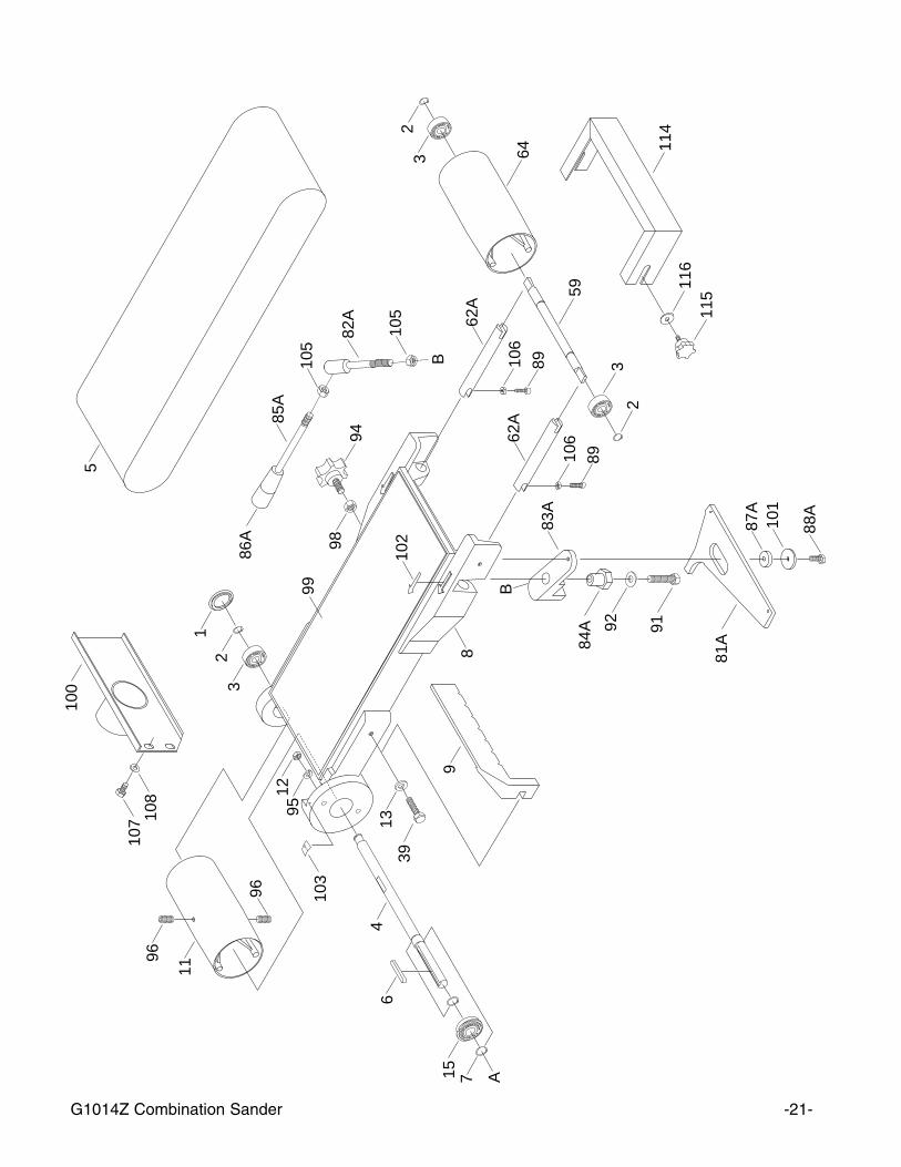
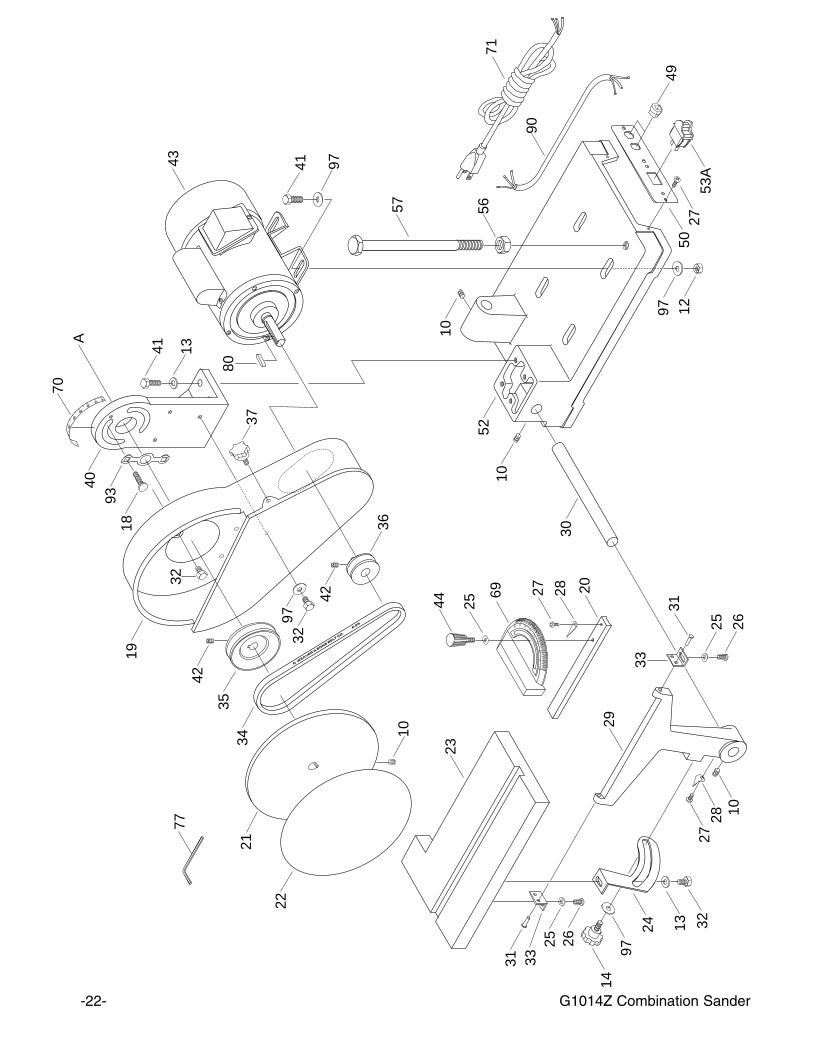
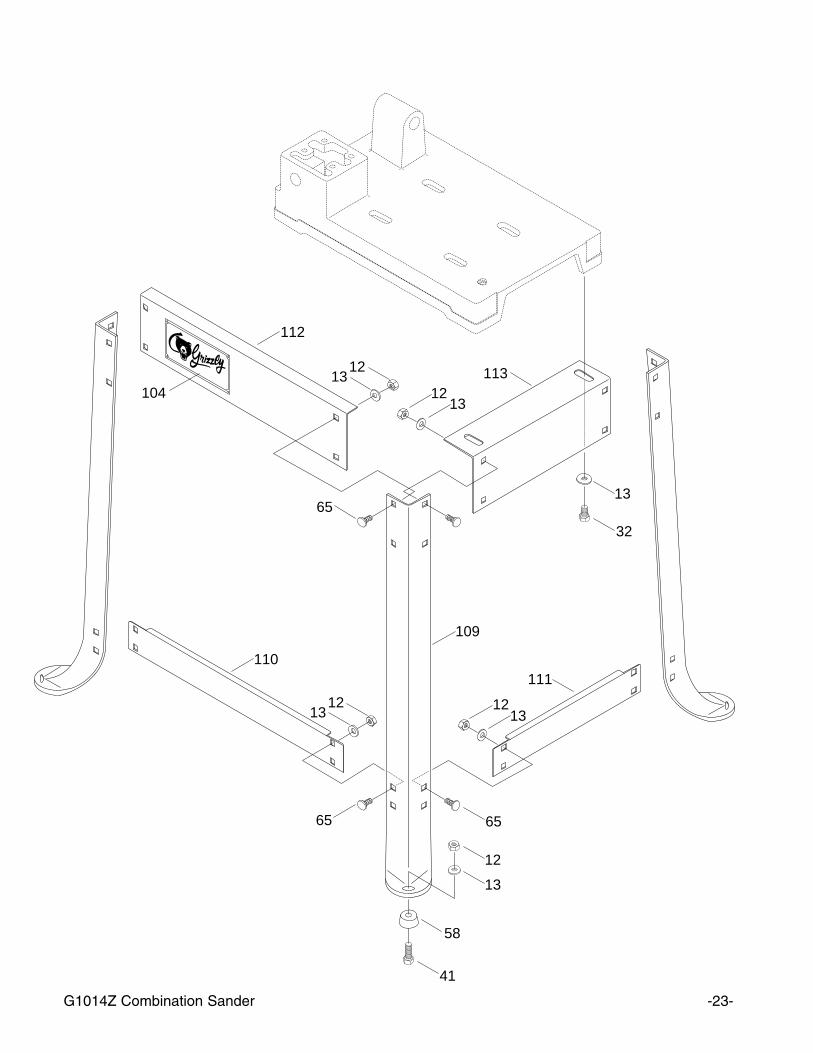
57 P1014057 SUPPORT 5⁄8''-11 x 9''58 P1014058 FOOT59 P1014059 IDLER ROLLER SHAFT62B P1014062B ROLLER ADJ BAR64 P1014064 IDLER ROLLER65 PCB05 CARRIAGE BOLT 5⁄16-18 x 3⁄4''69 P1014069 MITER BODY70 P1014070 SCALE71 P1014071 POWER CORD77 PAW04M ALLEN WRENCH 4MM80 PK23M KEY 5 X 5 X 2581A P1014081A ROCKER PLATE82A P1014082A LEVER, SHORT83A P1014083A ROCKER ARM84A P1014084A ECCENTRIC85A P1014085A LEVER, LONG86A P1014086A KNOB, 3⁄8-1687A P1014087A SPACER88A PB21 HEX BOLT 3⁄8"-16 x 3⁄4"89 PSB31 CAP SCREW 10-24 x 5⁄8"90 P1014090 MOTOR CORD91 PB16 HEX BOLT 3⁄8"-16 x 11⁄2"92 PW02 FLAT WASHER 3⁄8"93 P1014093 WASHER PLATE94 P1014094 KNOB95 PLW01 LOCK WASHER 5⁄16"96 PSS18 SETSCREW 5⁄16"-18 x 3⁄4"97 P1014097 FENDER WASHER98 PN11 HEX NUT 3⁄8''-2499 P1014099 GRAPHITE PAD100 P1014100 DUST PORT101 P1014101 FENDER WASHER 3⁄8"102 P1014102 DIRECTION SCALE103 P1014103 POINTER104 P1014104 NAME PLATE105 PN08 HEX NUT 3⁄8"-16106 PN07 HEX NUT 10-24107 PB19 HEX BOLT 1⁄4''-20 x 1⁄2''108 PW06 FLAT WASHER 1⁄4''109 P1014109 LEG110 P1014110 LOWER BRACE, LONG111 P1014111 LOWER BRACE, SHORT112 P1014112 UPPER BRACE, LONG113 P1014113 UPPER BRACE, SHORT114 P1014114 IDLER ROLLER GUARD
01 P1014001 DUST COVER02 PR03M SNAP RING 12MM03 P6201 BEARING 6201-2RS04 P1014004 DRIVE SHAFT05 G1214 SANDING BELT 6'' X 48''06 PK02M KEY 5 X 5X 4007 PR02M SNAP RING 14MM08 P1014008 SANDING BELT FRAME09 P1014009 BACK STOP10 PSS02 SETSCREW 5⁄16"-18 x 3⁄8"11 P1014011 DRIVE ROLLER12 PN02 HEX NUT 5⁄16"-1813 PW07 FLAT WASHER 5⁄16"14 P1014014 KNOB15 P1014015 BEARING 6202-2RSNR 18 PCB06 CARRIAGE BOLT 5⁄16"-18x11⁄4"19 P1014019 PULLEY COVER20 P1014020 TABLE LOCK HANDLE21 P1014021 CAST IRON DISC 9''22 G1217 SANDING DISC23 P1014023 TABLE24 P1014024 TRUNNION25 PW06 FLAT WASHER 1⁄4"26 PS04 PHILLIPS SCREW 1⁄4"-20 x 1⁄2"27 PS01 PHILLIPS SCREW 10-24 x 1⁄2"28 P1014028 POINTER29 P1014029 TABLE SUPPORT BRACKET30 P1014030 SUPPORT BAR31 P1014031 PIN32 PB09 HEX BOLT 5⁄16"-18 x 1⁄2"33 P1014033 TABLE MOUNT34 PVFM25 V-BELT FM2535 P1014035 PULLEY36 P1014036 MOTOR PULLEY37 P1014037 KNOB39 PB12 HEX BOLT 5⁄16"-18 x 11⁄4"40 P1014040 BRACKET41 PB03 HEX BOLT 5⁄16"-18 x 1''42 PSS03 SETSCREW 1⁄4"-20 x 3⁄8"43 P1014043 MOTOR44 P1014044 KNOB49 P1014049 STRAIN RELIEF50 P1014050 SWITCH PLATE52 P1014052 BASE53A PSW07 SWITCH56 PN04 HEX NUT 5⁄8''-11

G1014Z Combination Sander -25-
Grizzly Industrial, Inc. warrants every product it sells for a period of 1 year to the original purchaser fromthe date of purchase. This warranty does not apply to defects due directly or indirectly to misuse, abuse,negligence, accidents, repairs or alterations or lack of maintenance. This is Grizzly’s sole written warrantyand any and all warranties that may be implied by law, including any merchantability or fitness, for any par-ticular purpose, are hereby limited to the duration of this written warranty. We do not warrant or representthat the merchandise complies with the provisions of any law or acts unless the manufacturer so warrants.In no event shall Grizzly’s liability under this warranty exceed the purchase price paid for the product andany legal actions brought against Grizzly shall be tried in the State of Washington, County of Whatcom.
We shall in no event be liable for death, injuries to persons or property or for incidental, contingent, spe-cial, or consequential damages arising from the use of our products.
To take advantage of this warranty, contact us by mail or phone and give us all the details. We will thenissue you a “Return Number’’, which must be clearly posted on the outside as well as the inside of the car-ton. We will not accept any item back without this number. Proof of purchase must accompany the mer-chandise.
The manufacturers reserve the right to change specifications at any time because they constantly strive toachieve better quality equipment. We make every effort to ensure that our products meet high quality anddurability standards and we hope you never need to use this warranty.
Please feel free to write or call us if you have any questions about the machine or the manual.
Thank you again for your business and continued support. We hope to serve you again soon.
WARRANTY AND RETURNS