Embed Size (px)
Citation preview

2016/11 © Hiretech Part # 163829
OWNERS MANUAL & OPERATING INSTRUCTIONS
HT8 DRUM FLOOR SANDER
From Serial Number07294 (240/240 Volt) & 03415 (110/120 Volt)
WARNING
For safe operation of this machine, read and understand all instructions. Look for the ‘warning/caution’ symbol.
This symbol means that if you do not follow the instructions injury can occur to the operator and damage to the machine and floor may result.
WARNING: Risk of explosion.
Floor sanding can result in an explosive mixture of fine dust and air. Use this floor-sanding machine only in a well-ventilated area free from any flame, match or source of ignition.
WARNING: Risk of fire.
Never leave the floor sander unattended with dust in the dust bag.
WARNING: Risk of potential injury.
Moving Parts - to reduce the risk of injury, unplug the machine before replacing abrasive sheets or carrying out any form of adjustment or servicing.
NORTH AMERICAN SAFETY INSTRUCTIONS
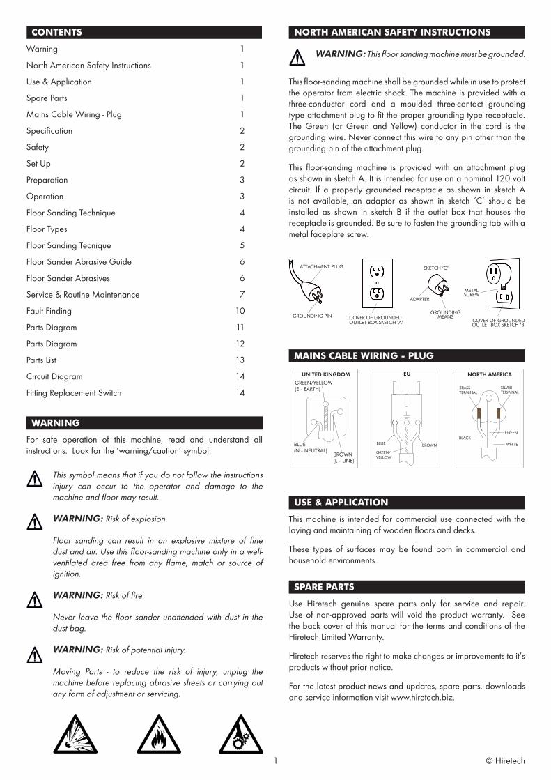
WARNING: This floor sanding machine must be grounded.
This floor-sanding machine shall be grounded while in use to protect the operator from electric shock. The machine is provided with a three-conductor cord and a moulded three-contact grounding type attachment plug to fit the proper grounding type receptacle. The Green (or Green and Yellow) conductor in the cord is the grounding wire. Never connect this wire to any pin other than the grounding pin of the attachment plug.
This floor-sanding machine is provided with an attachment plug as shown in sketch A. It is intended for use on a nominal 120 volt circuit. If a properly grounded receptacle as shown in sketch A is not available, an adaptor as shown in sketch ‘C’ should be installed as shown in sketch B if the outlet box that houses the receptacle is grounded. Be sure to fasten the grounding tab with a metal faceplate screw.
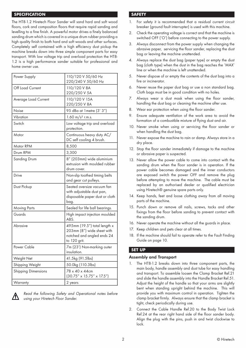
MAINS CABLE WIRING - PLUG
USE & APPLICATION
This machine is intended for commercial use connected with the laying and maintaining of wooden floors and decks.
These types of surfaces may be found both in commercial and household environments.
SPARE PARTS
Use Hiretech genuine spare parts only for service and repair. Use of non-approved parts will void the product warranty. See the back cover of this manual for the terms and conditions of the Hiretech Limited Warranty.
Hiretech reserves the right to make changes or improvements to it’s products without prior notice.
For the latest product news and updates, spare parts, downloads and service information visit www.hiretech.biz.
ATTACHMENT PLUG SKETCH ‘C’
METALSCREW
COVER OF GROUNDEDOUTLET BOX SKETCH ‘B’
ADAPTER
GROUNDINGMEANSCOVER OF GROUNDED
OUTLET BOX SKETCH ‘A’GROUNDING PIN
CONTENTS
Warning 1
North American Safety Instructions 1
Use & Application 1
Spare Parts 1
Mains Cable Wiring - Plug 1
Specification 2
Safety 2
Set Up 2
Preparation 3
Operation 3
Floor Sanding Technique 4
Floor Types 4
Floor Sanding Tecnique 5
Floor Sander Abrasive Guide 6
Floor Sander Abrasives 6
Service & Routine Maintenance 7
Fault Finding 10
Parts Diagram 11
Parts Diagram 12
Parts List 13
Circuit Diagram 14
Fitting Replacement Switch 14
1 © Hiretech
SPECIFICATION
The HT8-1.2 Hiretech Floor Sander will sand hard and soft wood floors, cork and composition floors that require rapid sanding and levelling to a fine finish. A powerful motor drives a finely balanced sanding drum which is covered in a unique drum rubber providing a high quality finish to both hard and soft woods and other surfaces. Completely self contained with a high efficiency dust pickup the machine breaks down into three simple component parts for easy transport. With low voltage trip and overload protection the HT8-1.2 is a high performance sander suitable for professional and home owner use.
Power Supply 110/120 V 50/60 Hz 220/240 V 50/60 Hz
Off Load Current 110/120 V 8A 220/250 V 5A
Average Load Current 110/120 V 15A220/250 V 8A
Noise 95 dBa at 1metre (3’ 3”)Vibration 1.60 m/s² r.m.s.Switch Low voltage trip and overload
protection.Motor Continuous heavy duty AC/
DC self cooling 4 brush.Motor RPM 8,500Drum RPM 3,300Sanding Drum 8” (203mm) wide aluminium
extrusion with moulded rubber drum cover.
Drive Non-slip toothed timing belts and gear cut pulleys.
Dust Pickup Seated oversize vacuum fan with adjustable dust pan, disposable paper dust or cloth bag.
Moving Parts Sealed for life ball bearings.Guards High impact injection moulded
ABS.Abrasive 495mm (19.5”) total length x
203mm (8”) wide sheet with notched and angled ends 24 to 120 grit.
Power Cable 7m (23’) Non-marking outer insulation.
Weight Net 41.5kg (91.5lbs)Shipping Weight 50.0kg (110.3lbs)Shipping Dimensions 78 x 40 x 44cm
(30.75” x 15.75” x 17.5”)Warranty 2 years
Read the following Safety and Operational notes before using your Hiretech Floor Sander.
SAFETY
1. For safety it is recommended that a residual current circuit breaker (ground fault interrupter) is used with this machine.
2. Check the operating voltage is correct and that the machine is switched OFF (‘O’) before connecting to the power supply.
3. Always disconnect from the power supply when changing the abrasive paper, servicing the floor sander, replacing the dust bag or leaving the machine unattended.
4. Always replace the dust bag (paper type) or empty the dust bag (cloth type) when the dust in the bag reaches the ‘MAX’ line or when the machine is left unattended.
5. Never dispose of or empty the contents of the dust bag into a fire or incinerator.
6. Never reuse the paper dust bag or use a non standard bag. Cloth bags must be in good condition with no holes.
7. Always wear a dust mask when using the floor sander, handling the dust bag or cleaning the machine after use.
8. Wear ear protection when using the floor sander.9. Ensure adequate ventilation of the work area to avoid the
formation of a combustible mixture of flying dust and air.10. Never smoke when using or servicing the floor sander or
when handling the dust bag.11. Never expose the machine to rain or damp. Always store in a
dry place.12. Stop the floor sander immediately if damage to the machine
or abrasive paper is suspected.13. Never allow the power cable to come into contact with the
sanding drum when the floor sander is in operation. If the power cable becomes damaged and the inner conductors are exposed switch the power OFF and remove the plug before attempting to move the machine. The cable must be replaced by an authorised dealer or qualified electrician using Hiretech® genuine spare parts only.
14. Keep hands, feet and loose clothing away from all moving parts of the machine.
15. Punch down or remove all nails, screws, tacks and other fixings from the floor before sanding to prevent contact with the sanding drum.
16. Never operate the machine without all the guards in place.17. Keep children and pets clear at all times.18. If the machine should fail to operate refer to the Fault Finding
Guide on page 10.
SET UP
Assembly and Transport1. The HT8-1.2 breaks down into three component parts, the
main body, handle assembly and dust tube for easy handling and transport. To assemble loosen the Clamp Bracket Ref.21 and slide the handle assembly into the Handle Bracket Ref.51. Adjust the height of the handle so that your arms are slightly bent when standing upright behind the machine. This will provide you with maximum control in operation. Tighten the clamp bracket firmly. Always ensure that the clamp bracket is tight, check periodically during use.
2. Connect the Cable Handle Ref.20 to the Body Twist Lock Ref.24 at the rear right hand side of the floor sander body. Align the plug with the pins, push in and twist clockwise to lock.
2 © Hiretech
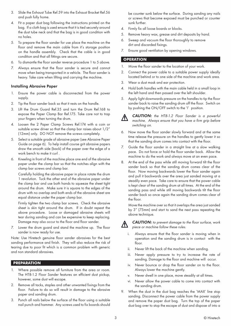
3. Slide the Exhaust Tube Ref.59 into the Exhaust Bracket Ref.56 and push fully home.
4. Fit a paper dust bag following the instructions printed on the bag. If a cloth bag is used ensure that it is tied securely around the dust tube neck and that the bag is in good condition with no holes.
5. To prepare the floor sander for use place the machine on the floor and remove the main cable from it’s storage position on the handle assembly. Check that the cable is in good condition and that all fittings are secure.
6. To dismantle the floor sander reverse procedure 1 to 5 above.7. Always ensure that the floor sander is secure and cannot
move when being transported in a vehicle. The floor sander is heavy. Take care when lifting and carrying the machine.
Installing Abrasive Paper
1. Ensure the power cable is disconnected from the power supply.
2. Tip the floor sander back so that it rests on the handle.3. Lift the Drum Guard Ref.35 and turn the Drum Ref.168 to
expose the Paper Clamp Bar Ref.175. Take care not to trap your fingers when turning the drum.
4. Loosen the 2 Paper Clamp Screws Ref.174 with a coin or suitable screw driver so that the clamp bar raises about 1/2“ (12mm) only. DO NOT remove the screws completely.
5. Select a suitable grade of abrasive paper (see Abrasive Paper Guide on page 6). To help install course grit abrasive papers draw the smooth side (back) of the paper over the edge of a work bench to make it curl .
6. Kneeling in front of the machine place one end of the abrasive paper under the clamp bar so that the notches align with the clamp bar screws and clamp bar.
Carefully holding the abrasive paper in place rotate the drum 1 revolution. Tuck the other end of the abrasive paper under the clamp bar and use both hands to squeeze the sheet tight around the drum. Make sure it is square to the edges of the drum with no overlap and both ends of the abrasive sheet are equal distance under the paper clamp bar.
Firmly tighten the two clamp bar screws. Check the abrasive sheet is skin tight around the drum. If in doubt repeat the above procedure. Loose or damaged abrasive sheets will tear during sanding and can be expensive to keep replacing. Damage may also occur to the floor and floor sander.
7. Lower the drum guard and stand the machine up. The floor sander is now ready for use.
Note: Use Hiretech genuine floor sander abrasives for the best sanding performance and finish. They will also reduce the risk of tearing due to poor fit which is a common problem with generic and non standard abrasives.
PREPARATION
1. Where possible remove all furniture from the area or room. The HT8-1.2 Floor Sander features an efficient dust pickup, however, some dust will escape.
2. Remove all tacks, staples and other unwanted fixings from the floor. Failure to do so will result in damage to the abrasive paper and sanding drum.
3. Punch all nails below the surface of the floor using a suitable nail punch and hammer. Any screws used to fix boards should
be counter sunk below the surface. During sanding any nails or screws that become exposed must be punched or counter sunk further.
4. Firmly fix all loose boards or blocks.5. Remove heavy wax, grease and dirt deposits by hand.6. Sweep and vacuum the floor thoroughly to remove
dirt and discarded fixings.7. Ensure good ventilation by opening windows.
OPERATION
1. Move the floor sander to the location of your work.2. Connect the power cable to a suitable power supply ideally
located behind or to one side of the machine and work area.3. Wear a dust mask and ear protection.4. Hold both handles with the main cable held in a small loop in
the left hand and then passed over the left shoulder. 5. Apply light downwards pressure on the handles to tip the floor
sander back to raise the sanding drum off the floor. Switch on by pushing the ON/OFF switch to the ‘I’ position.
CAUTION: the HT8-1.2 Floor Sander is a powerful machine. Always ensure that you have a firm grip before switching on.
6. Now move the floor sander slowly forward and at the same time release the pressure on the handles to gently lower it so that the sanding drum comes into contact with the floor.
7. Guide the floor sander in a straight line at a slow walking pace. Do not force or hold the floor sander back. Allow the machine to do the work and always move at an even pace.
8. At the end of the pass while still moving forward tilt the floor sander back so that the sanding drum comes clear of the floor. Now moving backwards lower the floor sander again and pull it backwards over the area just sanded moving at a steadily even pace. Take care to ensure that the power cable is kept clear of the sanding drum at all times. At the end of the sanding pass and while still moving backwards tilt the floor sander back so once again the sanding drum comes clear of the floor.
Move the machine over so that it overlaps the area just sanded by 3” (75mm) and start to sand the next pass repeating the above technique.
CAUTION: to prevent damage to the floor surface, work piece or machine follow these rules.
i. Always ensure that the floor sander is moving when in operation and the sanding drum is in contact with the floor.
ii. Never lift the back of the machine when sanding.iii. Never apply pressure to try to increase the rate of
sanding. Damage to the floor and machine will occur.iv. Never bounce or drop the floor sander on to the floor.
Always lower the machine gently.v. Never dwell in one place, move steadily at all times.vi. Never allow the power cable to come into contact with
the sanding drum.9. When the dust in the dust bag reaches the ‘MAX’ line stop
sanding. Disconnect the power cable from the power supply and remove the paper dust bag. Turn the top of the paper dust bag over to stop the escape of dust and dispose of into a
3 © Hiretech
suitable container. Never reuse the paper dust bag or empty it or dispose of it into a fire. If a cloth bag is used empty into a suitable container being careful to contain the dust. Do not dispose of the contents into a fire.
10. Fit a new paper dust bag or refit the cloth bag. Reconnect the floor sander to the power supply and continue sanding.
11. When taking a break from work disconnect the power cable from the supply, remove and dispose of the paper dust bag, or empty the cloth bag as detailed in 8. above. Never leave the floor sander unattended with the dust bag in place containing dust.
12. On completion disconnect the power cable from the supply. Remove and dispose of the paper dust bag, or empty the cloth bag as detailed in 8. above. Stow the cable on the handle assembly and if required dismantle for transportation. Carry out maintenance as recommended in Maintenance and Servicing.
DANGER: never leave the floor sander unattended with dust in the dust bag. Always remove the dust bag and dispose of into a suitable container.
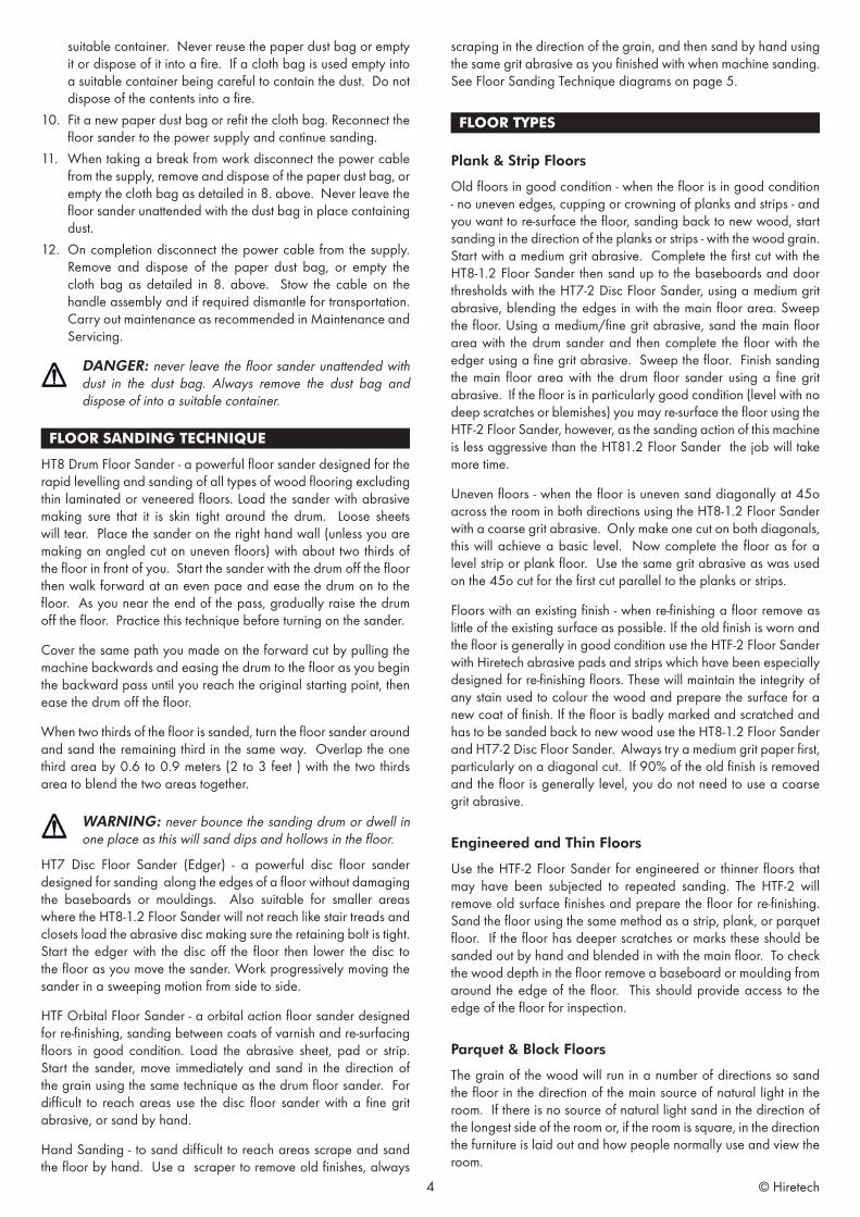
FLOOR SANDING TECHNIQUE
HT8 Drum Floor Sander - a powerful floor sander designed for the rapid levelling and sanding of all types of wood flooring excluding thin laminated or veneered floors. Load the sander with abrasive making sure that it is skin tight around the drum. Loose sheets will tear. Place the sander on the right hand wall (unless you are making an angled cut on uneven floors) with about two thirds of the floor in front of you. Start the sander with the drum off the floor then walk forward at an even pace and ease the drum on to the floor. As you near the end of the pass, gradually raise the drum off the floor. Practice this technique before turning on the sander.
Cover the same path you made on the forward cut by pulling the machine backwards and easing the drum to the floor as you begin the backward pass until you reach the original starting point, then ease the drum off the floor.
When two thirds of the floor is sanded, turn the floor sander around and sand the remaining third in the same way. Overlap the one third area by 0.6 to 0.9 meters (2 to 3 feet ) with the two thirds area to blend the two areas together.
WARNING: never bounce the sanding drum or dwell in one place as this will sand dips and hollows in the floor.
HT7 Disc Floor Sander (Edger) - a powerful disc floor sander designed for sanding along the edges of a floor without damaging the baseboards or mouldings. Also suitable for smaller areas where the HT8-1.2 Floor Sander will not reach like stair treads and closets load the abrasive disc making sure the retaining bolt is tight. Start the edger with the disc off the floor then lower the disc to the floor as you move the sander. Work progressively moving the sander in a sweeping motion from side to side.
HTF Orbital Floor Sander - a orbital action floor sander designed for re-finishing, sanding between coats of varnish and re-surfacing floors in good condition. Load the abrasive sheet, pad or strip. Start the sander, move immediately and sand in the direction of the grain using the same technique as the drum floor sander. For difficult to reach areas use the disc floor sander with a fine grit abrasive, or sand by hand.
Hand Sanding - to sand difficult to reach areas scrape and sand the floor by hand. Use a scraper to remove old finishes, always
scraping in the direction of the grain, and then sand by hand using the same grit abrasive as you finished with when machine sanding. See Floor Sanding Technique diagrams on page 5.
FLOOR TYPES
Plank & Strip Floors
Old floors in good condition - when the floor is in good condition - no uneven edges, cupping or crowning of planks and strips - and you want to re-surface the floor, sanding back to new wood, start sanding in the direction of the planks or strips - with the wood grain. Start with a medium grit abrasive. Complete the first cut with the HT8-1.2 Floor Sander then sand up to the baseboards and door thresholds with the HT7-2 Disc Floor Sander, using a medium grit abrasive, blending the edges in with the main floor area. Sweep the floor. Using a medium/fine grit abrasive, sand the main floor area with the drum sander and then complete the floor with the edger using a fine grit abrasive. Sweep the floor. Finish sanding the main floor area with the drum floor sander using a fine grit abrasive. If the floor is in particularly good condition (level with no deep scratches or blemishes) you may re-surface the floor using the HTF-2 Floor Sander, however, as the sanding action of this machine is less aggressive than the HT81.2 Floor Sander the job will take more time.
Uneven floors - when the floor is uneven sand diagonally at 45o across the room in both directions using the HT8-1.2 Floor Sander with a coarse grit abrasive. Only make one cut on both diagonals, this will achieve a basic level. Now complete the floor as for a level strip or plank floor. Use the same grit abrasive as was used on the 45o cut for the first cut parallel to the planks or strips.
Floors with an existing finish - when re-finishing a floor remove as little of the existing surface as possible. If the old finish is worn and the floor is generally in good condition use the HTF-2 Floor Sander with Hiretech abrasive pads and strips which have been especially designed for re-finishing floors. These will maintain the integrity of any stain used to colour the wood and prepare the surface for a new coat of finish. If the floor is badly marked and scratched and has to be sanded back to new wood use the HT8-1.2 Floor Sander and HT7-2 Disc Floor Sander. Always try a medium grit paper first, particularly on a diagonal cut. If 90% of the old finish is removed and the floor is generally level, you do not need to use a coarse grit abrasive.
Engineered and Thin Floors
Use the HTF-2 Floor Sander for engineered or thinner floors that may have been subjected to repeated sanding. The HTF-2 will remove old surface finishes and prepare the floor for re-finishing. Sand the floor using the same method as a strip, plank, or parquet floor. If the floor has deeper scratches or marks these should be sanded out by hand and blended in with the main floor. To check the wood depth in the floor remove a baseboard or moulding from around the edge of the floor. This should provide access to the edge of the floor for inspection.
Parquet & Block Floors
The grain of the wood will run in a number of directions so sand the floor in the direction of the main source of natural light in the room. If there is no source of natural light sand in the direction of the longest side of the room or, if the room is square, in the direction the furniture is laid out and how people normally use and view the room.
4 © Hiretech
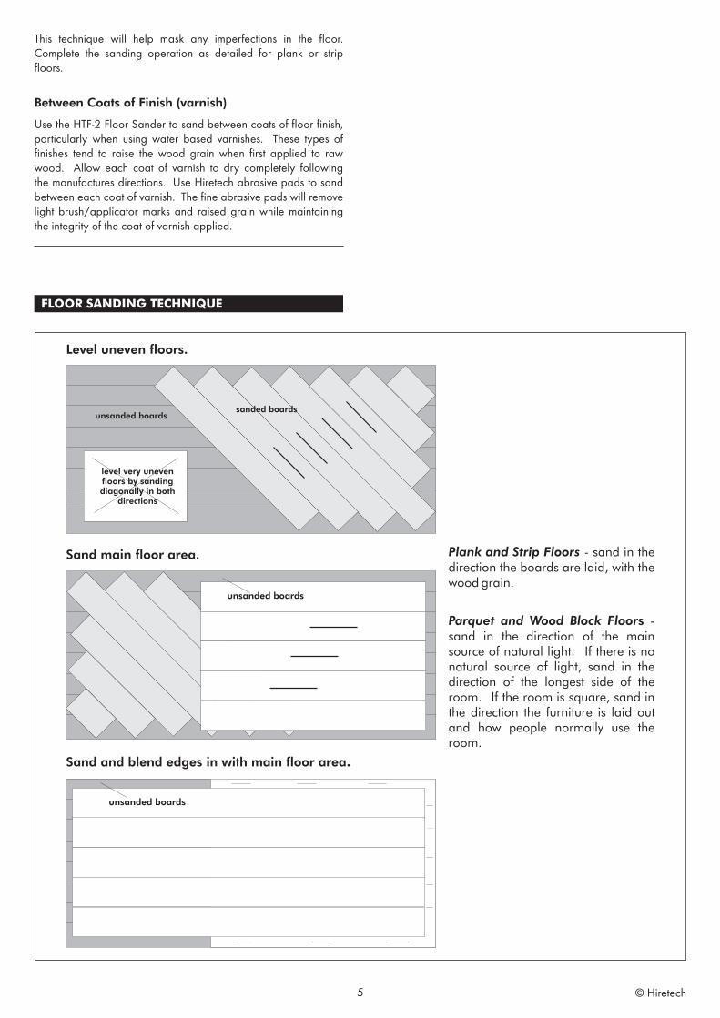
This technique will help mask any imperfections in the floor. Complete the sanding operation as detailed for plank or strip floors.
Between Coats of Finish (varnish)
Use the HTF-2 Floor Sander to sand between coats of floor finish, particularly when using water based varnishes. These types of finishes tend to raise the wood grain when first applied to raw wood. Allow each coat of varnish to dry completely following the manufactures directions. Use Hiretech abrasive pads to sand between each coat of varnish. The fine abrasive pads will remove light brush/applicator marks and raised grain while maintaining the integrity of the coat of varnish applied.
FLOOR SANDING TECHNIQUE
5 © Hiretech
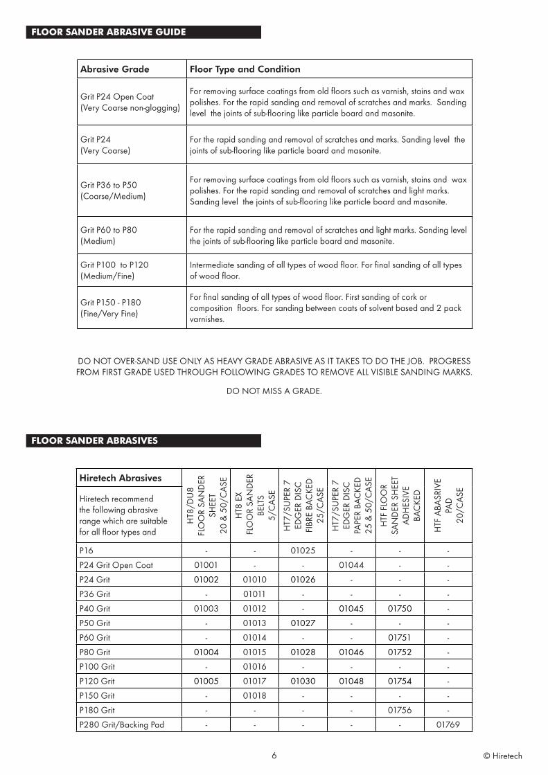
FLOOR SANDER ABRASIVE GUIDE
DO NOT OVER-SAND USE ONLY AS HEAVY GRADE ABRASIVE AS IT TAKES TO DO THE JOB. PROGRESS FROM FIRST GRADE USED THROUGH FOLLOWING GRADES TO REMOVE ALL VISIBLE SANDING MARKS.
DO NOT MISS A GRADE.
FLOOR SANDER ABRASIVES
Hiretech Abrasives
HT8
/DU
8FL
OO
R SA
ND
ER
SHEE
T20
& 5
0/C
ASE
HT8
EX
FLO
OR
SAN
DER
BE
LTS
5/C
ASE
HT7
/SU
PER
7ED
GER
DIS
CFI
BRE
BAC
KED
25/C
ASE
HT7
/SU
PER
7ED
GER
DIS
CPA
PER
BAC
KED
25 &
50/
CAS
E
HTF
FLO
OR
SAN
DER
SH
EET
ADH
ESIV
E BA
CKE
D
HTF
ABA
SRIV
E PA
D20
/CAS
E
Hiretech recommend the following abrasive range which are suitable for all floor types and
P16 - - 01025 - - -P24 Grit Open Coat 01001 - - 01044 - -P24 Grit 01002 01010 01026 - - -P36 Grit - 01011 - - - -P40 Grit 01003 01012 - 01045 01750 -P50 Grit - 01013 01027 - - -P60 Grit - 01014 - - 01751 -P80 Grit 01004 01015 01028 01046 01752 -P100 Grit - 01016 - - - -P120 Grit 01005 01017 01030 01048 01754 -P150 Grit - 01018 - - - -P180 Grit - - - - 01756 -P280 Grit/Backing Pad - - - - - 01769
Abrasive Grade Floor Type and Condition
Grit P24 Open Coat(Very Coarse non-glogging)
For removing surface coatings from old floors such as varnish, stains and wax polishes. For the rapid sanding and removal of scratches and marks. Sanding level the joints of sub-flooring like particle board and masonite.
Grit P24(Very Coarse)
For the rapid sanding and removal of scratches and marks. Sanding level the joints of sub-flooring like particle board and masonite.
Grit P36 to P50(Coarse/Medium)
For removing surface coatings from old floors such as varnish, stains and wax polishes. For the rapid sanding and removal of scratches and light marks. Sanding level the joints of sub-flooring like particle board and masonite.
Grit P60 to P80(Medium)
For the rapid sanding and removal of scratches and light marks. Sanding level the joints of sub-flooring like particle board and masonite.
Grit P100 to P120(Medium/Fine)
Intermediate sanding of all types of wood floor. For final sanding of all types of wood floor.
Grit P150 - P180(Fine/Very Fine)
For final sanding of all types of wood floor. First sanding of cork or composition floors. For sanding between coats of solvent based and 2 pack varnishes.
6 © Hiretech
SERVICE & ROUTINE MAINTENANCE
CAUTION: maintenance and repairs must be carried out by authorised personnel only. To prevent injury, always remove the power cable from the power supply before undertaking any work on the machine. Do not operate the floor sander unless it is fully assembled and all guards are in place. Use Hiretech genuine spare parts only.
General
1. Always make a list when first examining the machine, to remind you of parts or action needed on completion of repair/service.
2. The HT8-1.2 is subject to high speeds. All screws should be fitted using a suitable thread lock compound.
3. On completion of any work or service on an electrical tool or appliance statutory safety tests must be carried out by a competent person and recorded (see Testing for Electrical Safety page 8).
4. The HT8-1.2 needs no lubrication during routine servicing.5. Always ensure that the electrical supply is disconnected
before starting any routine servicing or repair.
Visual Inspection
1. Check that the drum guard Ref.35 is in good condition and functioning correctly. Ensure that the Warning Label Ref.36 is present and legible.
2. Check all other guards and mechanical parts are in good condition.
3. Examine the power cable Ref.39 and the handle cable Ref.20. If the outer insulation shows the slightest of abrasions or the inner conductors are exposed, then the cable must be replaced. The cable must not be repaired with tape or insulation sleeve
4. Examine both the mains plug and the interconnecting socket, Body Twist Lock Ref.24. The plugs must be opened and examined (see Electrical Testing page 8).
5. If a cloth type bag is in service check the condition, old clogged cloth dust bags make for an inefficient dust pickup.
6. Ensure that all labels are present and in good condition.
Drive Belts
1. To examine the condition of the Drive Belts Ref.164 and Ref.165 remove the four screws Ref.83 and the Belt Guard Ref.81.
2. Lift the Fan Belt Ref.165 while rotating the pulley remove the fan belt. Repeat for the Drum Belt Ref.164.
CAUTION: take care to avoid trapping your fingers when removing or replacing the drive belts.
3. Examine the pulleys for wear, worn or damaged pulleys should be replaced
4. To reduce the instance of belt breakage, examine the drive belts, look for cracks or fraying and replace if necessary with new belts. To replace reverse the above procedure taking care to avoid bending the belts tighter than the pulley diameter as this can result in damaged belts. Refit the belt guard.
Dust Control System
1. For efficient dust pick up ensure that cloth type dust bags are clean and unclogged and that the intake is clear and properly adjusted.
2. Turn the machine on to its side and loosen the three Screws Ref.71 and remove the Dust Shoe Ref.72 and clear any obstruction. The grit from the abrasive paper can wear away the leading edge of the dust shoe, if this has occurred then file or grind the leading edge level before refitting.
Install the dust shoe ensuring that the clearance between the shoe and the drum is maintained at 3/8“ (10mm).
Lubrication
1. The HT8-1.2 is completely lubricated. The bearings are sealed and do not require lubrication. In the unlikely event that a bearing requires replacement use a Hiretech genuine spare part only as the grease contained in these bearings is special. A standard bearing is not suitable and may result in further damage.
Care of Motor
1. The motor must be kept free from grease and dust.2. The motor brushes must be checked regularly, inspect the
brushes every three months or every 500 hours of use, whichever comes first.
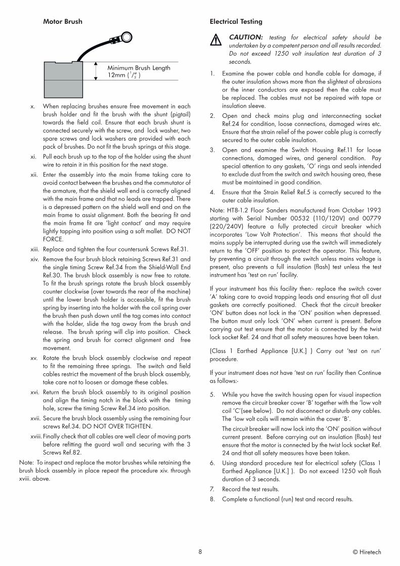
3. Replace ALL FOUR motor brushes when any one brush has worn to 12mm (1/2”) or less in length. Brushes MUST slide freely in the brush holders.
4. To inspect and replace motor Brushes Ref.104, with the brush block assembly removed.i. Remove the three Screws Ref.82 and remove the Wall
End Guard Ref.84 to expose the motor brush assembly.ii. Remove the four retaining Screws Ref.31 from the Shield
Wall End Ref.30, insert two of the screws into the ‘jacking holes’ situated adjacent to the countersunk retaining holes.
iii. Carefully tighten these screws until the shield wall end is jacked clear of the outer casting. Withdraw the shield-wall end.
iv. With the brush block assembly complete and the connecting leads still attached. You will note that as the brush block assembly is withdrawn the brushes spring towards the center and often the brush springs fall clear as the brushes are no longer at the height to retain them. Take care not to lose any springs.
v. To remove a brush spring with a brush in the operating position push the brush spring down and towards the brush and lift out.
vi. Using a cross recess screwdriver remove the four brush shunt (pigtail) retaining Screws Ref.105 and lock Washers Ref.100.
vii. Remove the four brushes. Remove the two ‘jacking’ screws.
viii. Thoroughly clean the brush assembly and housing using a soft brush and a suitable vacuum cleaner.
ix. Inspect the four brushes for damage or wear and if any one brush is found to be damaged or worn to a length of 12mm (1/2”) or less in length then replace all four brushes.
7 © Hiretech
Motor Brush
x. When replacing brushes ensure free movement in each brush holder and fit the brush with the shunt (pigtail) towards the field coil. Ensure that each brush shunt is connected securely with the screw, and lock washer, two spare screws and lock washers are provided with each pack of brushes. Do not fit the brush springs at this stage.
xi. Pull each brush up to the top of the holder using the shunt wire to retain it in this position for the next stage.
xii. Enter the assembly into the main frame taking care to avoid contact between the brushes and the commutator of the armature, that the shield wall end is correctly aligned with the main frame and that no leads are trapped. There is a depressed pattern on the shield wall end and on the main frame to assist alignment. Both the bearing fit and the main frame fit are ‘light contact’ and may require lightly tapping into position using a soft mallet. DO NOT FORCE.
xiii. Replace and tighten the four countersunk Screws Ref.31.xiv. Remove the four brush block retaining Screws Ref.31 and
the single timing Screw Ref.34 from the Shield-Wall End Ref.30. The brush block assembly is now free to rotate. To fit the brush springs rotate the brush block assembly counter clockwise (over towards the rear of the machine) until the lower brush holder is accessible, fit the brush spring by inserting into the holder with the coil spring over the brush then push down until the tag comes into contact with the holder, slide the tag away from the brush and release. The brush spring will clip into position. Check the spring and brush for correct alignment and free movement.
xv. Rotate the brush block assembly clockwise and repeat to fit the remaining three springs. The switch and field cables restrict the movement of the brush block assembly, take care not to loosen or damage these cables.
xvi. Return the brush block assembly to its original position and align the timing notch in the block with the timing hole, screw the timing Screw Ref.34 into position.
xvii. Secure the brush block assembly using the remaining four screws Ref.34. DO NOT OVER TIGHTEN.
xviii. Finally check that all cables are well clear of moving parts before refitting the guard wall and securing with the 3 Screws Ref.82.
Note: To inspect and replace the motor brushes while retaining the brush block assembly in place repeat the procedure xiv. through xviii. above.
Minimum Brush Length12mm ( /” )1
2
Electrical Testing
CAUTION: testing for electrical safety should be undertaken by a competent person and all results recorded. Do not exceed 1250 volt insulation test duration of 3 seconds.
1. Examine the power cable and handle cable for damage, if the outer insulation shows more than the slightest of abrasions or the inner conductors are exposed then the cable must be replaced. The cables must not be repaired with tape or insulation sleeve.
2. Open and check mains plug and interconnecting socket Ref.24 for condition, loose connections, damaged wires etc. Ensure that the strain relief of the power cable plug is correctly secured to the outer cable insulation.
3. Open and examine the Switch Housing Ref.11 for loose connections, damaged wires, and general condition. Pay special attention to any gaskets, ‘O’ rings and seals intended to exclude dust from the switch and switch housing area, these must be maintained in good condition.
4. Ensure that the Strain Relief Ref.5 is correctly secured to the outer cable insulation.
Note: HT8-1.2 Floor Sanders manufactured from October 1993 starting with Serial Number 00532 (110/120V) and 00779 (220/240V) feature a fully protected circuit breaker which incorporates ‘Low Volt Protection’. This means that should the mains supply be interrupted during use the switch will immediately return to the ‘OFF’ position to protect the operator. This feature, by preventing a circuit through the switch unless mains voltage is present, also prevents a full insulation (flash) test unless the test instrument has ‘test on run’ facility.
If your instrument has this facility then:- replace the switch cover ‘A’ taking care to avoid trapping leads and ensuring that all dust gaskets are correctly positioned. Check that the circuit breaker ‘ON’ button does not lock in the ‘ON’ position when depressed. The button must only lock ‘ON’ when current is present. Before carrying out test ensure that the motor is connected by the twist lock socket Ref. 24 and that all safety measures have been taken.
(Class 1 Earthed Appliance [U.K.] ) Carry out ‘test on run’ procedure.
If your instrument does not have ‘test on run’ facility then Continue as follows:-
5. While you have the switch housing open for visual inspection remove the circuit breaker cover ‘B’ together with the ‘low volt coil ‘C’(see below). Do not disconnect or disturb any cables. The ‘low volt coils will remain within the cover ‘B’.
The circuit breaker will now lock into the ‘ON’ position without current present. Before carrying out an insulation (flash) test ensure that the motor is connected by the twist lock socket Ref. 24 and that all safety measures have been taken.
6. Using standard procedure test for electrical safety (Class 1 Earthed Appliance [U.K.] ). Do not exceed 1250 volt flash duration of 3 seconds.
7. Record the test results. 8. Complete a functional (run) test and record results.
8 © Hiretech
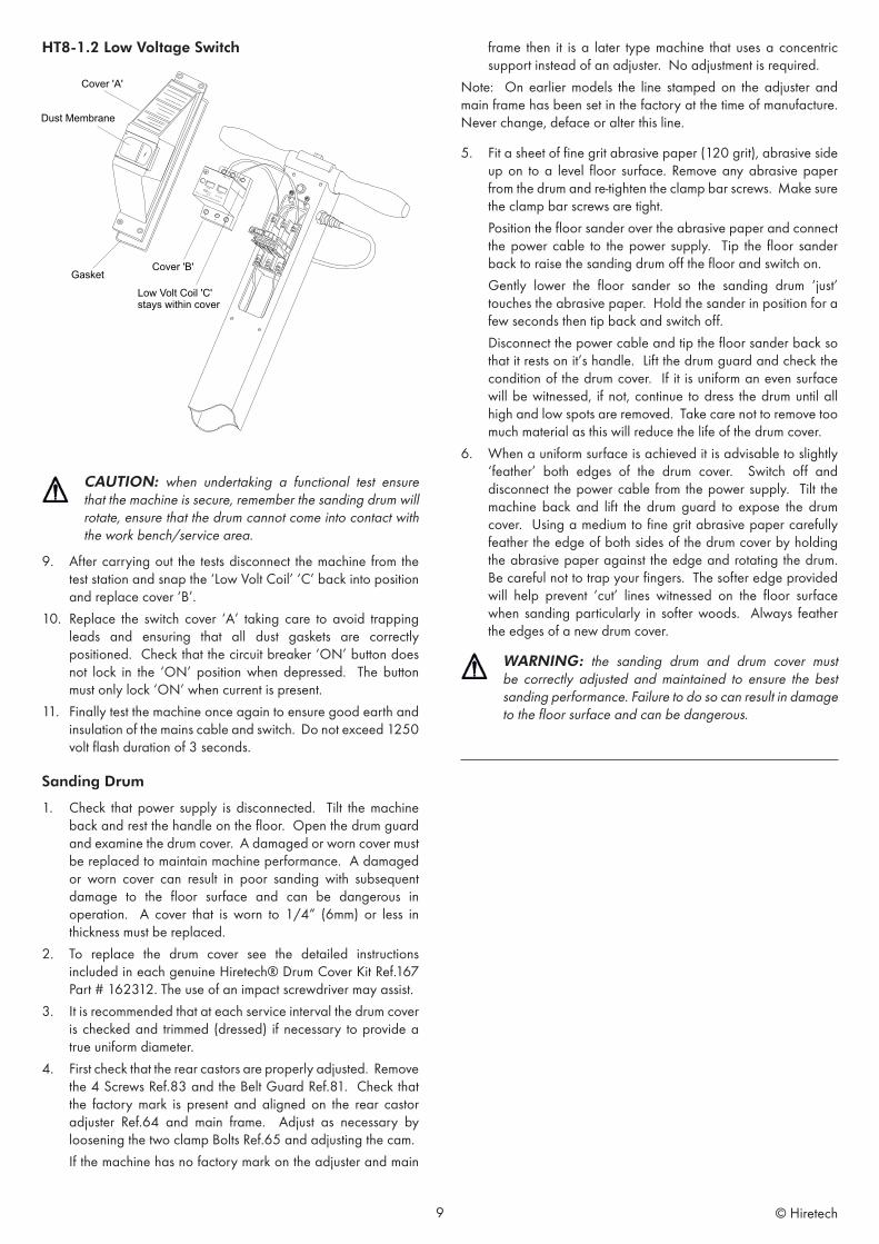
HT8-1.2 Low Voltage Switch
CAUTION: when undertaking a functional test ensure that the machine is secure, remember the sanding drum will rotate, ensure that the drum cannot come into contact with the work bench/service area.
9. After carrying out the tests disconnect the machine from the test station and snap the ‘Low Volt Coil’ ‘C’ back into position and replace cover ‘B’.
10. Replace the switch cover ‘A’ taking care to avoid trapping leads and ensuring that all dust gaskets are correctly positioned. Check that the circuit breaker ‘ON’ button does not lock in the ‘ON’ position when depressed. The button must only lock ‘ON’ when current is present.
11. Finally test the machine once again to ensure good earth and insulation of the mains cable and switch. Do not exceed 1250 volt flash duration of 3 seconds.
Sanding Drum
1. Check that power supply is disconnected. Tilt the machine back and rest the handle on the floor. Open the drum guard and examine the drum cover. A damaged or worn cover must be replaced to maintain machine performance. A damaged or worn cover can result in poor sanding with subsequent damage to the floor surface and can be dangerous in operation. A cover that is worn to 1/4“ (6mm) or less in thickness must be replaced.
2. To replace the drum cover see the detailed instructions included in each genuine Hiretech® Drum Cover Kit Ref.167 Part # 162312. The use of an impact screwdriver may assist.
3. It is recommended that at each service interval the drum cover is checked and trimmed (dressed) if necessary to provide a true uniform diameter.
4. First check that the rear castors are properly adjusted. Remove the 4 Screws Ref.83 and the Belt Guard Ref.81. Check that the factory mark is present and aligned on the rear castor adjuster Ref.64 and main frame. Adjust as necessary by loosening the two clamp Bolts Ref.65 and adjusting the cam.
If the machine has no factory mark on the adjuster and main
frame then it is a later type machine that uses a concentric support instead of an adjuster. No adjustment is required.
Note: On earlier models the line stamped on the adjuster and main frame has been set in the factory at the time of manufacture. Never change, deface or alter this line.
5. Fit a sheet of fine grit abrasive paper (120 grit), abrasive side up on to a level floor surface. Remove any abrasive paper from the drum and re-tighten the clamp bar screws. Make sure the clamp bar screws are tight.
Position the floor sander over the abrasive paper and connect the power cable to the power supply. Tip the floor sander back to raise the sanding drum off the floor and switch on.
Gently lower the floor sander so the sanding drum ‘just’ touches the abrasive paper. Hold the sander in position for a few seconds then tip back and switch off.
Disconnect the power cable and tip the floor sander back so that it rests on it’s handle. Lift the drum guard and check the condition of the drum cover. If it is uniform an even surface will be witnessed, if not, continue to dress the drum until all high and low spots are removed. Take care not to remove too much material as this will reduce the life of the drum cover.
6. When a uniform surface is achieved it is advisable to slightly ‘feather’ both edges of the drum cover. Switch off and disconnect the power cable from the power supply. Tilt the machine back and lift the drum guard to expose the drum cover. Using a medium to fine grit abrasive paper carefully feather the edge of both sides of the drum cover by holding the abrasive paper against the edge and rotating the drum. Be careful not to trap your fingers. The softer edge provided will help prevent ‘cut’ lines witnessed on the floor surface when sanding particularly in softer woods. Always feather the edges of a new drum cover.
WARNING: the sanding drum and drum cover must be correctly adjusted and maintained to ensure the best sanding performance. Failure to do so can result in damage to the floor surface and can be dangerous.
9 © Hiretech
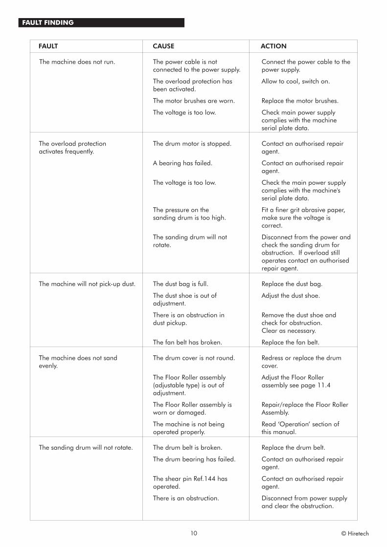
FAULT FINDING
10 © Hiretech
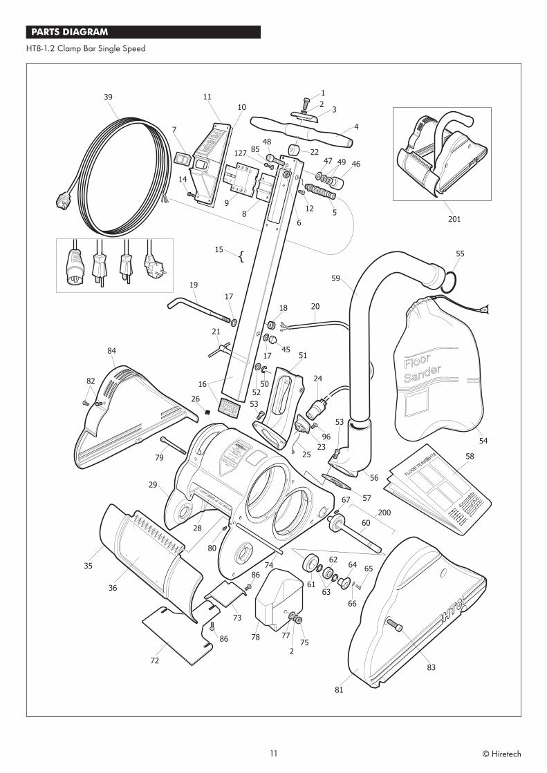
PARTS DIAGRAM
HT8-1.2 Clamp Bar Single Speed
11 © Hiretech
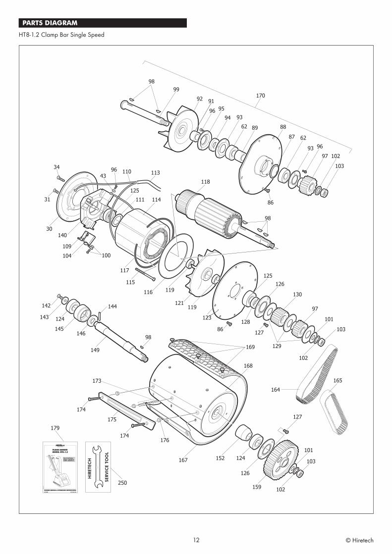
PARTS DIAGRAM
HT8-1.2 Clamp Bar Single Speed
12 © Hiretech
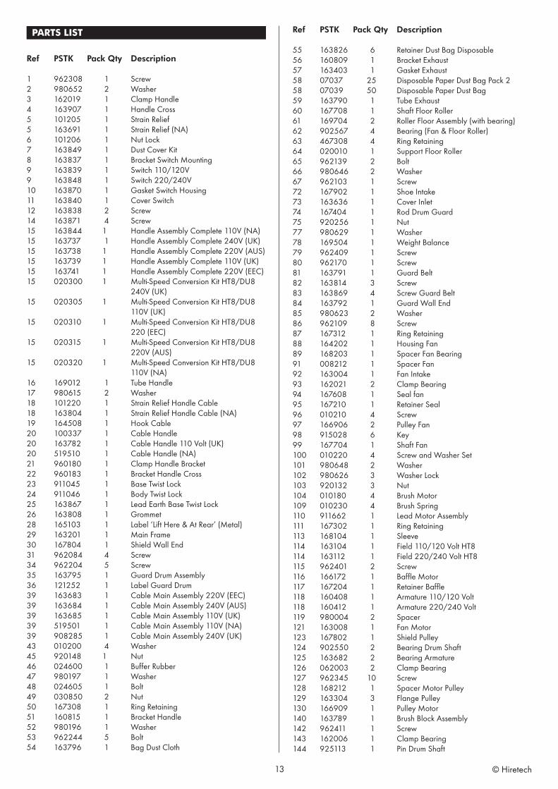
PARTS LIST
Ref PSTK Pack Qty Description
1 962308 1 Screw2 980652 2 Washer3 162019 1 Clamp Handle4 163907 1 Handle Cross5 101205 1 Strain Relief5 163691 1 Strain Relief (NA)6 101206 1 Nut Lock7 163849 1 Dust Cover Kit8 163837 1 Bracket Switch Mounting9 163839 1 Switch 110/120V9 163848 1 Switch 220/240V10 163870 1 Gasket Switch Housing11 163840 1 Cover Switch12 163838 2 Screw14 163871 4 Screw15 163844 1 Handle Assembly Complete 110V (NA)15 163737 1 Handle Assembly Complete 240V (UK)15 163738 1 Handle Assembly Complete 220V (AUS)15 163739 1 Handle Assembly Complete 110V (UK)15 163741 1 Handle Assembly Complete 220V (EEC)15 020300 1 Multi-Speed Conversion Kit HT8/DU8 240V (UK)15 020305 1 Multi-Speed Conversion Kit HT8/DU8 110V (UK)15 020310 1 Multi-Speed Conversion Kit HT8/DU8 220 (EEC)15 020315 1 Multi-Speed Conversion Kit HT8/DU8 220V (AUS)15 020320 1 Multi-Speed Conversion Kit HT8/DU8 110V (NA)16 169012 1 Tube Handle17 980615 2 Washer18 101220 1 Strain Relief Handle Cable18 163804 1 Strain Relief Handle Cable (NA)19 164508 1 Hook Cable20 100337 1 Cable Handle20 163782 1 Cable Handle 110 Volt (UK)20 519510 1 Cable Handle (NA)21 960180 1 Clamp Handle Bracket22 960183 1 Bracket Handle Cross23 911045 1 Base Twist Lock24 911046 1 Body Twist Lock25 163867 1 Lead Earth Base Twist Lock26 163808 1 Grommet28 165103 1 Label ‘Lift Here & At Rear’ (Metal)29 163201 1 Main Frame30 167804 1 Shield Wall End31 962084 4 Screw34 962204 5 Screw35 163795 1 Guard Drum Assembly36 121252 1 Label Guard Drum39 163683 1 Cable Main Assembly 220V (EEC)39 163684 1 Cable Main Assembly 240V (AUS)39 163685 1 Cable Main Assembly 110V (UK)39 519501 1 Cable Main Assembly 110V (NA)39 908285 1 Cable Main Assembly 240V (UK)43 010200 4 Washer45 920148 1 Nut46 024600 1 Buffer Rubber47 980197 1 Washer48 024605 1 Bolt49 030850 2 Nut50 167308 1 Ring Retaining51 160815 1 Bracket Handle52 980196 1 Washer53 962244 5 Bolt54 163796 1 Bag Dust Cloth
Ref PSTK Pack Qty Description
55 163826 6 Retainer Dust Bag Disposable56 160809 1 Bracket Exhaust57 163403 1 Gasket Exhaust58 07037 25 Disposable Paper Dust Bag Pack 258 07039 50 Disposable Paper Dust Bag 59 163790 1 Tube Exhaust60 167708 1 Shaft Floor Roller61 169704 2 Roller Floor Assembly (with bearing)62 902567 4 Bearing (Fan & Floor Roller)63 467308 4 Ring Retaining64 020010 1 Support Floor Roller65 962139 2 Bolt66 980646 2 Washer67 962103 1 Screw72 167902 1 Shoe Intake73 163636 1 Cover Inlet74 167404 1 Rod Drum Guard75 920256 1 Nut77 980629 1 Washer78 169504 1 Weight Balance79 962409 1 Screw80 962170 1 Screw81 163791 1 Guard Belt82 163814 3 Screw83 163869 4 Screw Guard Belt84 163792 1 Guard Wall End85 980623 2 Washer86 962109 8 Screw87 167312 1 Ring Retaining88 164202 1 Housing Fan89 168203 1 Spacer Fan Bearing91 008212 1 Spacer Fan92 163004 1 Fan Intake93 162021 2 Clamp Bearing94 167608 1 Seal fan95 167210 1 Retainer Seal96 010210 4 Screw97 166906 2 Pulley Fan98 915028 6 Key99 167704 1 Shaft Fan100 010220 4 Screw and Washer Set101 980648 2 Washer102 980626 3 Washer Lock103 920132 3 Nut104 010180 4 Brush Motor109 010230 4 Brush Spring110 911662 1 Lead Motor Assembly111 167302 1 Ring Retaining113 168104 1 Sleeve114 163104 1 Field 110/120 Volt HT8114 163112 1 Field 220/240 Volt HT8115 962401 2 Screw116 166172 1 Baffle Motor117 167204 1 Retainer Baffle118 160408 1 Armature 110/120 Volt118 160412 1 Armature 220/240 Volt119 980004 2 Spacer121 163008 1 Fan Motor123 167802 1 Shield Pulley124 902550 2 Bearing Drum Shaft125 163682 2 Bearing Armature126 062003 2 Clamp Bearing127 962345 10 Screw128 168212 1 Spacer Motor Pulley129 163304 3 Flange Pulley130 166909 1 Pulley Motor140 163789 1 Brush Block Assembly142 962411 1 Screw143 162006 1 Clamp Bearing144 925113 1 Pin Drum Shaft
13 © Hiretech
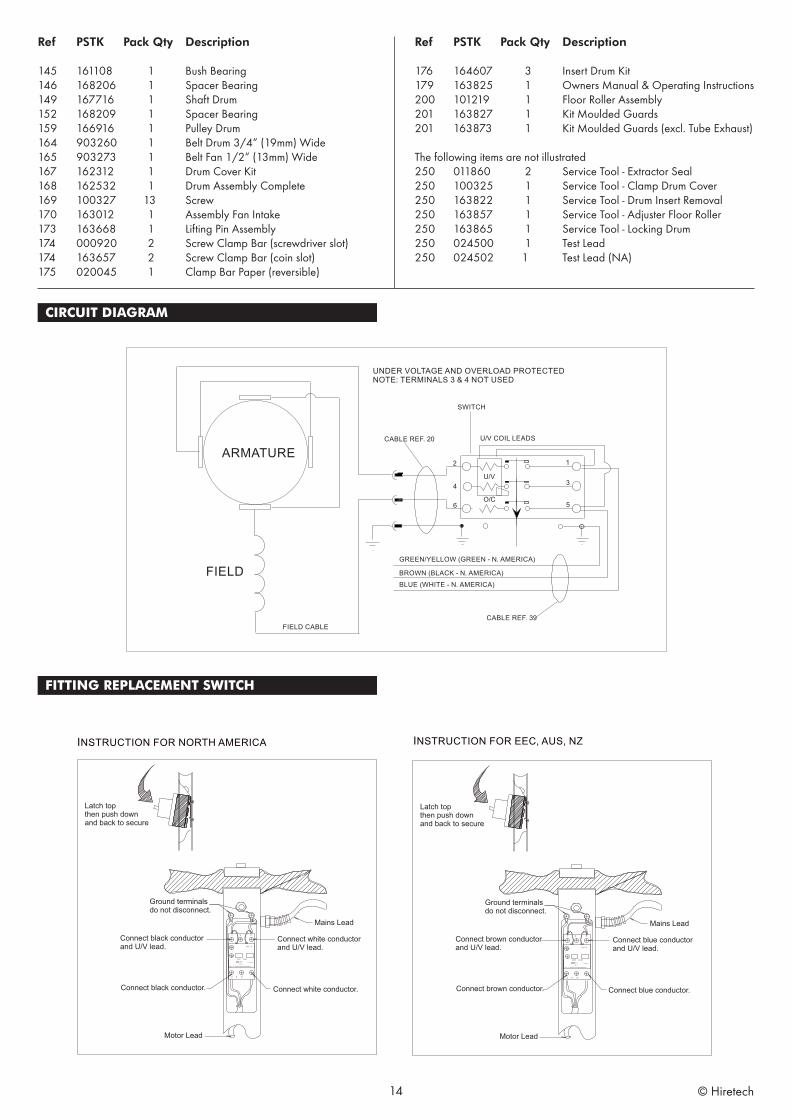
Ref PSTK Pack Qty Description
145 161108 1 Bush Bearing146 168206 1 Spacer Bearing149 167716 1 Shaft Drum152 168209 1 Spacer Bearing159 166916 1 Pulley Drum164 903260 1 Belt Drum 3/4” (19mm) Wide165 903273 1 Belt Fan 1/2” (13mm) Wide167 162312 1 Drum Cover Kit168 162532 1 Drum Assembly Complete169 100327 13 Screw170 163012 1 Assembly Fan Intake173 163668 1 Lifting Pin Assembly174 000920 2 Screw Clamp Bar (screwdriver slot)174 163657 2 Screw Clamp Bar (coin slot)175 020045 1 Clamp Bar Paper (reversible)
Ref PSTK Pack Qty Description
176 164607 3 Insert Drum Kit179 163825 1 Owners Manual & Operating Instructions200 101219 1 Floor Roller Assembly201 163827 1 Kit Moulded Guards201 163873 1 Kit Moulded Guards (excl. Tube Exhaust)
The following items are not illustrated 250 011860 2 Service Tool - Extractor Seal250 100325 1 Service Tool - Clamp Drum Cover250 163822 1 Service Tool - Drum Insert Removal250 163857 1 Service Tool - Adjuster Floor Roller250 163865 1 Service Tool - Locking Drum250 024500 1 Test Lead250 024502 1 Test Lead (NA)
CIRCUIT DIAGRAM
FITTING REPLACEMENT SWITCH
14 © Hiretech
HIR
ETEC
H L
IMIT
ED W
ARRA
NTY
Hire
tech
war
rant
s to
the
orig
inal
pur
chas
er th
at th
e H
irete
ch m
achi
ne c
over
ed b
y th
is w
arra
nty
is fre
e fro
m d
efec
ts in
wor
kman
ship
and
mat
eria
ls. S
houl
d an
y pa
rt fa
il in
the
perio
d of
two
year
s fro
m th
e da
te o
f the
orig
inal
pur
chas
e as
a re
sult
of a
def
ect,
Hire
tech
will
(at i
t’s o
ptio
n) e
ither
repa
ir or
repl
ace
the
part
with
out c
harg
e pr
ovid
ed th
at th
e m
achi
ne h
as b
een
oper
ated
in a
ccor
danc
e w
ith th
e O
wne
rs M
anua
l and
Ope
ratin
g In
struc
tions
.
Shou
ld a
ny s
uch
defe
ct a
rise,
ple
ase
cont
act y
our
near
est a
utho
rised
rep
air
agen
t. S
tand
ard
serv
ice
over
land
m
ainl
and
freig
ht c
osts
will
be re
fund
ed o
n w
arra
nty
repa
irs a
t the
sole
disc
retio
n of
Hire
tech
or t
he a
utho
rised
repa
ir ag
ent.
If th
e re
pair
is no
n-w
arra
nty,
the
custo
mer
will
be a
dvise
d be
fore
any
wor
k is
unde
rtake
n.
This
war
rant
y is
the
sole
war
rant
y by
Hire
tech
and
is in
lieu
of a
ll ot
her w
arra
ntie
s exp
ress
or i
mpl
ied
and
rele
ases
H
irete
ch fr
om a
ll ot
her o
blig
atio
ns a
nd li
abilit
ies.
This
war
rant
y do
es n
ot a
pply
to n
orm
al w
ear a
nd te
ar to
the
mac
hine
, and
in p
artic
ular
doe
s not
cov
er n
orm
al w
ear
parts
such
as m
ains
cab
le, w
heel
s, sw
itche
s, re
lays
, bru
shes
, rub
ber p
arts,
hos
es a
nd b
earin
gs.
This
war
rant
y al
so
does
not
cov
er, a
nd H
irete
ch w
ill no
t be
liabl
e fo
r, ex
cess
ive w
ear c
ause
d by
abn
orm
al u
se.
Hire
tech
will
unde
r no
circ
umsta
nces
be
liabl
e fo
r alte
ratio
ns to
the
mac
hine
or f
or d
amag
e ca
used
by
third
per
sons
, or
for
misu
se o
r ab
use
of th
e m
achi
ne, o
r da
mag
e ca
used
dur
ing
trans
porta
tion.
Re
pairs
of t
he m
achi
ne m
ade
or a
ttem
pted
by
pers
ons
othe
r th
an th
ose
spec
ifica
lly a
utho
rised
by
Hire
tech
sha
ll re
nder
this
war
rant
y vo
id a
nd
Hire
tech
will
not b
e lia
ble
for s
uch
repa
irs, t
he c
ost o
f suc
h re
pairs
, or t
he c
onse
quen
ces
of s
uch
repa
irs.
Whe
re
spar
e pa
rts a
re u
sed
on th
e m
achi
ne a
nd th
ey d
o no
t con
form
to H
irete
ch s
peci
ficat
ions
, thi
s w
arra
nty
will
be
rend
ered
voi
d an
d H
irete
ch w
ill no
t be
liabl
e.
Hire
tech
will
not b
e lia
ble
for a
ny in
dire
ct o
r con
sequ
entia
l los
s, da
mag
e, c
ost o
r exp
ense
of a
ny k
ind
wha
teve
r and
ho
wev
er c
ause
d w
heth
er a
risin
g un
der c
ontra
ct, t
ort (
incl
udin
g ne
glig
ence
) or o
ther
wise
incl
udin
g (w
ithou
t lim
itatio
n)
loss
of p
rodu
ctio
n, lo
ss o
f pro
fits o
r con
tract
s or o
f ope
ratin
g tim
e or
goo
dwill
or a
ntic
ipat
ed sa
vings
.
Ever
y ef
fort
has
been
mad
e to
pre
sent
all
info
rmat
ion
in th
is pu
blic
atio
n ac
cura
tely,
how
ever
no
liabi
lity
is ac
cept
ed f
or a
ny in
clus
ions
or
advic
e gi
ven
or f
or o
miss
ions
fro
m th
is pu
blic
atio
n. H
irete
ch r
eser
ves
the
right
to m
ake
chan
ges
or im
prov
emen
ts to
its
prod
ucts
with
out p
rior
notic
e. H
irete
ch® is
a r
egist
ered
tra
dem
ark
of H
ire T
echn
icia
ns G
roup
Ltd
., al
l oth
er tr
adem
arks
are
the
prop
erty
of t
heir
resp
ectiv
e ow
ners
. ©
Hire
Tec
hnic
ians
Gro
up Lt
d.
MAN
UFA
CTU
RED
BY
HIR
E TE
CH
NIC
IAN
S G
RO
UP
LIM
ITED
CH
ALK
HIL
L H
OU
SE,
8 C
HA
LK H
ILL,
WA
TFO
RD
,H
ERTS
, W
D19 4
BH.
UN
ITED
KIN
GD
OM
TEL:
+44 (
0)1
923 3
32424
FAX:
+44 (
0)1
923 3
32425
E-m
ail:
sale
s@h
iret
ech
.biz
W
eb:
ww
w.h
iret
ech
.bi z
© Hiretech