Embed Size (px)
Citation preview
Warranty Registration Card must be filled out by the customer and mailed within thirty (30) days of installa-tion in order to gain warranty coverage.
When receiving the CHALLENGER, any claims for damage or shortage in shipment must be filed immedi-ately against the transportation company by the consignee.
Leave all documentation received with appliance with owner for future reference.
* I N S T A L L A T I O N A N D M A I N T E N A N C E * * I N S T A L L A T I O N A N D M A I N T E N A N C E * M A N U A LM A N U A L
2010-1Challenger Manual
If the information in this manual is not followed exactly, a fire or explosion mayresult causing property damage, personal injury or death.
FOR YOUR SAFETY• Do not store or use gasoline or other flammable vapors and liquids in the vicinity ofthis or any other appliance.
• WHAT TO DO IF YOU SMELL GAS- Do not try to light any appliance- Do not touch any electrical switch; do not use any phone in your building.- Immediately call your gas supplier from a neighbor’s phone. Follow the gassupplier’s instructions.
- If you cannot reach your gas supplier, call the fire department.Installation and service must be performed by a qualified installer, service agency or thegas supplier.
CombinationBoilerWater Heater
/and or
Date: 11/25/13
WARNING
NOTICE
PRODUCT AND SAFETY INFORMATION
Definitions. . . . . . . . . . . . . . . . . . . . . . . . . . . . . . . . . . . . . . . . . . . . . . . . . . . 1Product and Safety Information . . . . . . . . . . . . . . . . . . . . . . . . . . . . . . . . . . 2-3
SECTION I - PRE-INSTALLATION ITEMS
Code Compliance . . . . . . . . . . . . . . . . . . . . . . . . . . . . . . . . . . . . . . . . . . . . . 4Determining Product Location . . . . . . . . . . . . . . . . . . . . . . . . . . . . . . . . . . . 4Boiler or Water Heater Replacement . . . . . . . . . . . . . . . . . . . . . . . . . . . . . . 5Clearances . . . . . . . . . . . . . . . . . . . . . . . . . . . . . . . . . . . . . . . . . . . . . . . . . . . 5Residential Garage Installations . . . . . . . . . . . . . . . . . . . . . . . . . . . . . . . . . 5Boiler Freeze Protection Feature . . . . . . . . . . . . . . . . . . . . . . . . . . . . . . . . . 6
SECTION II - COMBUSTION AIR AND VENTING
Combustion Air Contamination . . . . . . . . . . . . . . . . . . . . . . . . . . . . . . . . . . 7Ventilation Air Requirements . . . . . . . . . . . . . . . . . . . . . . . . . . . . . . . . . . . . 8Combustion Air and Vent Piping . . . . . . . . . . . . . . . . . . . . . . . . . . . . . . . . . 8Removal of an Existing Boiler and/or Water Heater
from a Common Vent System . . . . . . . . . . . . . . . . . . 9Commonwealth of Massachusetts Installation . . . . . . . . . . . . . . . . . . . . . . . 10
SECTION III - APPLIANCE PREPARATIONS
Shipping and Handling Instructions . . . . . . . . . . . . . . . . . . . . . . . . . . . . . . . 11Wall Mounting Installation . . . . . . . . . . . . . . . . . . . . . . . . . . . . . . . . . . . . . . 11Wall Mounting Guidelines . . . . . . . . . . . . . . . . . . . . . . . . . . . . . . . . . . . . . . 12Stud Walls - Installation . . . . . . . . . . . . . . . . . . . . . . . . . . . . . . . . . . . . . . . . 12Wall Bracket Installation - Solid Walls . . . . . . . . . . . . . . . . . . . . . . . . . . . . 12Appliance Mounting . . . . . . . . . . . . . . . . . . . . . . . . . . . . . . . . . . . . . . . . . . . 13Piping Support Bracket. . . . . . . . . . . . . . . . . . . . . . . . . . . . . . . . . . . . . . . . . 13
SECTION IV - BOILER PIPING
General Piping Requirements . . . . . . . . . . . . . . . . . . . . . . . . . . . . . . . . . . . . 14Pressure Relief Valve . . . . . . . . . . . . . . . . . . . . . . . . . . . . . . . . . . . . . . . . . . 14Low Water Cut Off/CH Pressure Sensor . . . . . . . . . . . . . . . . . . . . . . . . . . . 14Additional Limit Control . . . . . . . . . . . . . . . . . . . . . . . . . . . . . . . . . . . . . . . 16Backflow Preventer. . . . . . . . . . . . . . . . . . . . . . . . . . . . . . . . . . . . . . . . . . . . 16Boiler System Piping Applications. . . . . . . . . . . . . . . . . . . . . . . . . . . . . . . . 16Expansion Tank and Makeup Water . . . . . . . . . . . . . . . . . . . . . . . . . . . . . . . 16
Diaphragm Expansion Tank . . . . . . . . . . . . . . . . . . . . . . . . . . . . . . . 16Closed-Type Expansion Tank . . . . . . . . . . . . . . . . . . . . . . . . . . . . . . 17
Table of Contents
i

Circulator . . . . . . . . . . . . . . . . . . . . . . . . . . . . . . . . . . . . . . . . . . . . . . . . . . . 17Sizing Primary Piping. . . . . . . . . . . . . . . . . . . . . . . . . . . . . . . . . . . . . . . . . . 17System Piping - Zone Circulators. . . . . . . . . . . . . . . . . . . . . . . . . . . . . . . . . 17System Piping - Zone Valves . . . . . . . . . . . . . . . . . . . . . . . . . . . . . . . . . . . . 17Near Boiler Piping Diagrams . . . . . . . . . . . . . . . . . . . . . . . . . . . . . . . . . . . . 18System Piping - Radiant Heating . . . . . . . . . . . . . . . . . . . . . . . . . . . . . . . . . 19System Piping - SMART Indirect Fired Water Heater (I.F.W.H). . . . . . . . . 19System Piping - Special Applications. . . . . . . . . . . . . . . . . . . . . . . . . . . . . . 19Central Heating (CH) System Piping Diagrams. . . . . . . . . . . . . . . . . . . . . . 20
SECTION V - DOMESTIC PIPING
General Notes . . . . . . . . . . . . . . . . . . . . . . . . . . . . . . . . . . . . . . . . . . . . . . . . 21Operating Restrictions . . . . . . . . . . . . . . . . . . . . . . . . . . . . . . . . . . . . . . . . . 21-22Pressure Relief Valve - Standard Installations . . . . . . . . . . . . . . . . . . . . . . . 22Temperature & Pressure (T&P) Relief Valve
- Storage Tank or SMART Installations . . . . . . . . . . . . . . . . . . 23Drain Valves . . . . . . . . . . . . . . . . . . . . . . . . . . . . . . . . . . . . . . . . . . . . . . . . . 23Thermal Expansion . . . . . . . . . . . . . . . . . . . . . . . . . . . . . . . . . . . . . . . . . . . . 23Water Hammer . . . . . . . . . . . . . . . . . . . . . . . . . . . . . . . . . . . . . . . . . . . . . . . 24Vacuum Breaker - Storage Tank or SMART Installations . . . . . . . . . . . . . . 24General Piping Requirements . . . . . . . . . . . . . . . . . . . . . . . . . . . . . . . . . . . . 24Thermostatic Mixing Valve . . . . . . . . . . . . . . . . . . . . . . . . . . . . . . . . . . . . . 24-25Recirculation Piping . . . . . . . . . . . . . . . . . . . . . . . . . . . . . . . . . . . . . . . . . . . 25Storage Tank Installations. . . . . . . . . . . . . . . . . . . . . . . . . . . . . . . . . . . . . . . 25Setting The Thermostatic Mixing Valve. . . . . . . . . . . . . . . . . . . . . . . . . . . . 25Domestic Piping Diagrams . . . . . . . . . . . . . . . . . . . . . . . . . . . . . . . . . . . . . . 26-27
SECTION VI - INSTALLING VENT / COMBUSTION AIR & CONDENSATE DRAIN
Installing Vent and Combustion Air . . . . . . . . . . . . . . . . . . . . . . . . . . . . . . . 28Installing Condensate Drain Assembly. . . . . . . . . . . . . . . . . . . . . . . . . . . . . 28-29
SECTION VII - GAS PIPING
Gas Supply Piping Connection. . . . . . . . . . . . . . . . . . . . . . . . . . . . . . . . . . . 30Natural Gas
Pipe Sizing -Natural Gas . . . . . . . . . . . . . . . . . . . . . . . . . . . . . . . . . 31Natural Gas Supply Pressure Requirements. . . . . . . . . . . . . . . . . . . 31Natural Gas Orifice Requirements . . . . . . . . . . . . . . . . . . . . . . . . . . 31
Propane GasPipe Sizing - Propane Gas . . . . . . . . . . . . . . . . . . . . . . . . . . . . . . . . 32Propane Gas Supply Pressure Requirements . . . . . . . . . . . . . . . . . . 32Propane Gas Orifice Requirements . . . . . . . . . . . . . . . . . . . . . . . . . 32
Table of Contents
ii
SECTION VIII - INTERNAL WIRING
General Requirements. . . . . . . . . . . . . . . . . . . . . . . . . . . . . . . . . . . . . . . . . . 33CHALLENGER Factory Wiring Diagrams. . . . . . . . . . . . . . . . . . . . . . . . . 34
SECTION IX - EXTERNAL WIRING
Installation Compliance . . . . . . . . . . . . . . . . . . . . . . . . . . . . . . . . . . . . . . . . 35Line Voltage Connections. . . . . . . . . . . . . . . . . . . . . . . . . . . . . . . . . . . . . . . 35Control Module Circulator AMP Ratings. . . . . . . . . . . . . . . . . . . . . . . . . . . 35Low Voltage Connections. . . . . . . . . . . . . . . . . . . . . . . . . . . . . . . . . . . . . . . 36Thermostat Wiring . . . . . . . . . . . . . . . . . . . . . . . . . . . . . . . . . . . . . . . . . . . . 36CH Circulator . . . . . . . . . . . . . . . . . . . . . . . . . . . . . . . . . . . . . . . . . . . . . . . . 37DHW Circulator for Optional Smart IFWH. . . . . . . . . . . . . . . . . . . . . . . . . 37System Circulator - Zone Valve Application . . . . . . . . . . . . . . . . . . . . . . . . 37Outdoor Reset Control . . . . . . . . . . . . . . . . . . . . . . . . . . . . . . . . . . . . . . . . . 37External Wiring Diagrams . . . . . . . . . . . . . . . . . . . . . . . . . . . . . . . . . . . . . . 38-39
SECTION X - START-UP PREPARATION
Check Boiler System Water ChemistryWater pH Level 6.5 to 8.5 . . . . . . . . . . . . . . . . . . . . . . . . . . . . . . . . 40Water Total Hardness Less Than 7 Grains/Gallon . . . . . . . . . . . . . . 40Chlorinated Water . . . . . . . . . . . . . . . . . . . . . . . . . . . . . . . . . . . . . . . 40
Flush Boiler and Domestic System to Remove Sediment . . . . . . . . . . . . . . 40Check and Test Antifreeze . . . . . . . . . . . . . . . . . . . . . . . . . . . . . . . . . . . . . . 40Use of Antifreeze in the Boiler System . . . . . . . . . . . . . . . . . . . . . . . . . . . . 41Filling the Boiler System . . . . . . . . . . . . . . . . . . . . . . . . . . . . . . . . . . . . . . . 41Check Low Water Cut-Off/CH Pressure Sensor . . . . . . . . . . . . . . . . . . . . . 41Check for Gas Leaks. . . . . . . . . . . . . . . . . . . . . . . . . . . . . . . . . . . . . . . . . . . 42Check Thermostat Circuit. . . . . . . . . . . . . . . . . . . . . . . . . . . . . . . . . . . . . . . 42Inspection of Condensate Drain Assembly. . . . . . . . . . . . . . . . . . . . . . . . . . 42
SECTION XI - START-UP PROCEDURES
Final Checks Before Start-Up. . . . . . . . . . . . . . . . . . . . . . . . . . . . . . . . . . . . 43CHALLENGER Start-Up . . . . . . . . . . . . . . . . . . . . . . . . . . . . . . . . . . . . . . . 43If CHALLENGER Does Not Start Correctly. . . . . . . . . . . . . . . . . . . . . . . . 43Check the CHALLENGER and System. . . . . . . . . . . . . . . . . . . . . . . . . . . . 43-44Operating Instructions. . . . . . . . . . . . . . . . . . . . . . . . . . . . . . . . . . . . . . . . . . 45Appliance ON/OFF. . . . . . . . . . . . . . . . . . . . . . . . . . . . . . . . . . . . . . . . . . . . 46Set Boiler Maximum Central Heating (CH) Set Point Temperature . . . . . . 46
Table of Contents
iii
Operation Verification - Space Heating . . . . . . . . . . . . . . . . . . . . . . . . . . . . 46-47Set DHW Set Point Temperature . . . . . . . . . . . . . . . . . . . . . . . . . . . . . . . . . 47Operation Verification - Domestic Hot Water . . . . . . . . . . . . . . . . . . . . . . . 47-48Control Display
Appliance ON/OFF. . . . . . . . . . . . . . . . . . . . . . . . . . . . . . . . . . . . . . 49Units . . . . . . . . . . . . . . . . . . . . . . . . . . . . . . . . . . . . . . . . . . . . . . . . . 49Additional DHW Functions . . . . . . . . . . . . . . . . . . . . . . . . . . . . . . . 49Highfire . . . . . . . . . . . . . . . . . . . . . . . . . . . . . . . . . . . . . . . . . . . . . . . 50Lowfire . . . . . . . . . . . . . . . . . . . . . . . . . . . . . . . . . . . . . . . . . . . . . . . 50Flame Current . . . . . . . . . . . . . . . . . . . . . . . . . . . . . . . . . . . . . . . . . . 50Control Software Version . . . . . . . . . . . . . . . . . . . . . . . . . . . . . . . . . 50Display . . . . . . . . . . . . . . . . . . . . . . . . . . . . . . . . . . . . . . . . . . . . . . . 51
Setting the Appliance Parameters . . . . . . . . . . . . . . . . . . . . . . . . . . . . . . . . . 52Fluctuating Water Temperature. . . . . . . . . . . . . . . . . . . . . . . . . . . . . . . . . . . 53Error (Hard Lockout) Mode . . . . . . . . . . . . . . . . . . . . . . . . . . . . . . . . . . . . . 53Error (Hard Lockout) Codes. . . . . . . . . . . . . . . . . . . . . . . . . . . . . . . . . . . . . 54
SECTION XII - OUTDOOR RESET CONTROL
Mounting the Outdoor Sensor . . . . . . . . . . . . . . . . . . . . . . . . . . . . . . . . . . . 55Wiring the Sensor . . . . . . . . . . . . . . . . . . . . . . . . . . . . . . . . . . . . . . . . . . . . . 55Adjusting Outdoor Reset Curve
CH Maximum Boiler Operating Temperature. . . . . . . . . . . . . . . . . 56CH Minimum Boiler Operating Temperature Setpoint (Parameter 5) . . . . . . . . 56CH Reset Curve Coldest Day (Parameter 6) . . . . . . . . . . . . . . . . . . 56CH Reset Curve Warmest Day (Parameter 7) . . . . . . . . . . . . . . . . . 56
Changing Outdoor Reset Parameters . . . . . . . . . . . . . . . . . . . . . . . . . . . . . . 56Outdoor Reset Curve Example . . . . . . . . . . . . . . . . . . . . . . . . . . . . . . . . . . . 57
SECTION XIII - CHECK-OUT PROCEDURES
Check-Out Procedures . . . . . . . . . . . . . . . . . . . . . . . . . . . . . . . . . . . . . . . . . 58
SECTION XIV - INSTALLATION RECORD
Installation Record . . . . . . . . . . . . . . . . . . . . . . . . . . . . . . . . . . . . . . . . . . . . 59
SECTIONS XV - MAINTENANCE SCHEDULE
Service Technician - General . . . . . . . . . . . . . . . . . . . . . . . . . . . . . . . . . . . . 60Owner Maintenance . . . . . . . . . . . . . . . . . . . . . . . . . . . . . . . . . . . . . . . . . . . 60
Table of Contents
iv
SECTION XVI - MAINTENANCE PROCEDURES
Annual Maintenance ProceduresReported Problems . . . . . . . . . . . . . . . . . . . . . . . . . . . . . . . . . . . . . . 61Check Surrounding Area. . . . . . . . . . . . . . . . . . . . . . . . . . . . . . . . . . 61Inspect Burner Area . . . . . . . . . . . . . . . . . . . . . . . . . . . . . . . . . . . . . 61Check System Piping . . . . . . . . . . . . . . . . . . . . . . . . . . . . . . . . . . . . 61Clean Condensate Drain Assembly . . . . . . . . . . . . . . . . . . . . . . . . . 62Check Ventilation Air Openings . . . . . . . . . . . . . . . . . . . . . . . . . . . . 62Inspect Vent and Combustion Air Piping . . . . . . . . . . . . . . . . . . . . . 62Check Boiler System . . . . . . . . . . . . . . . . . . . . . . . . . . . . . . . . . . . . 62Removing Internal Flue and Condensate Pan for Inspection. . . . . . 62-63Check Expansion Tank . . . . . . . . . . . . . . . . . . . . . . . . . . . . . . . . . . . 64Check Relief Valve (s) . . . . . . . . . . . . . . . . . . . . . . . . . . . . . . . . . . . 64Inspection of Ignition Electrode . . . . . . . . . . . . . . . . . . . . . . . . . . . . 64Check Ignition Wiring and Ground Wiring . . . . . . . . . . . . . . . . . . . 64Check Control Wiring. . . . . . . . . . . . . . . . . . . . . . . . . . . . . . . . . . . . 66Check Control Settings . . . . . . . . . . . . . . . . . . . . . . . . . . . . . . . . . . . 66Perform Start-Up and Checkout Procedure . . . . . . . . . . . . . . . . . . . 66Check Burner Flame . . . . . . . . . . . . . . . . . . . . . . . . . . . . . . . . . . . . . 66Check Combustion Levels . . . . . . . . . . . . . . . . . . . . . . . . . . . . . . . . 67Clean Boiler Heat Exchanger . . . . . . . . . . . . . . . . . . . . . . . . . . . . . . 67Clean Domestic Heat Exchanger . . . . . . . . . . . . . . . . . . . . . . . . . . . 67-68Review with Owner . . . . . . . . . . . . . . . . . . . . . . . . . . . . . . . . . . . . . 68Handling Previously Fired Combustion Chamber Insulation . . . . . 68
REPLACEMENT PARTS
Replacement Parts. . . . . . . . . . . . . . . . . . . . . . . . . . . . . . . . . . . . . . . . . . . . . 69-75
PRODUCT SPECIFICATIONS
Specifications . . . . . . . . . . . . . . . . . . . . . . . . . . . . . . . . . . . . . . . . . . . . . . . . 76Specifications Water Heater . . . . . . . . . . . . . . . . . . . . . . . . . . . . . . . . . . . . . 77-78Specification Boiler . . . . . . . . . . . . . . . . . . . . . . . . . . . . . . . . . . . . . . . . . . . 79-82
Table of Contents
v
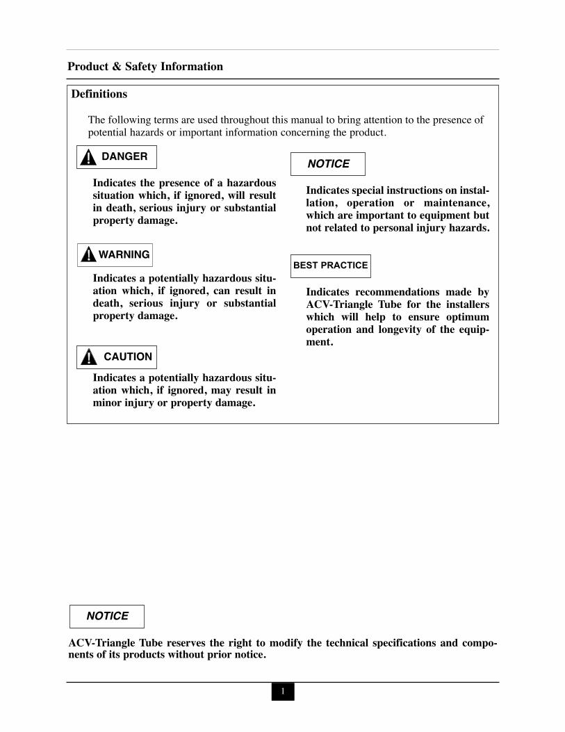
Indicates the presence of a hazardoussituation which, if ignored, will resultin death, serious injury or substantialproperty damage.
Indicates a potentially hazardous situ-ation which, if ignored, can result indeath, serious injury or substantialproperty damage.
Indicates a potentially hazardous situ-ation which, if ignored, may result inminor injury or property damage.
Indicates special instructions on instal-lation, operation or maintenance,which are important to equipment butnot related to personal injury hazards.
Indicates recommendations made byACV-Triangle Tube for the installerswhich will help to ensure optimumoperation and longevity of the equip-ment.
NOTICE
WARNING
CAUTION
BEST PRACTICE
DANGER
The following terms are used throughout this manual to bring attention to the presence ofpotential hazards or important information concerning the product.
ACV-Triangle Tube reserves the right to modify the technical specifications and compo-nents of its products without prior notice.
NOTICE
Definitions
Product & Safety Information
1
Product & Safety Information
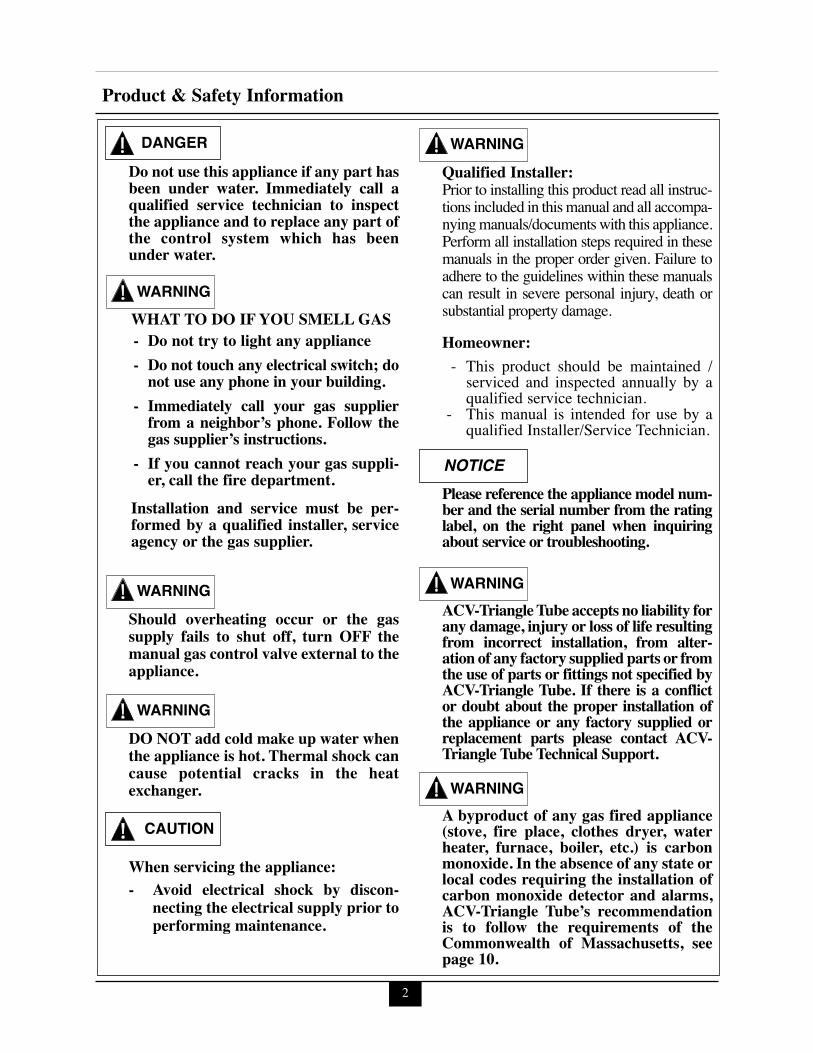
Do not use this appliance if any part hasbeen under water. Immediately call aqualified service technician to inspectthe appliance and to replace any part ofthe control system which has beenunder water.
WHAT TO DO IF YOU SMELL GAS- Do not try to light any appliance- Do not touch any electrical switch; donot use any phone in your building.
- Immediately call your gas supplierfrom a neighbor’s phone. Follow thegas supplier’s instructions.
- If you cannot reach your gas suppli-er, call the fire department.
Installation and service must be per-formed by a qualified installer, serviceagency or the gas supplier.
Should overheating occur or the gassupply fails to shut off, turn OFF themanual gas control valve external to theappliance.
DO NOT add cold make up water whenthe appliance is hot. Thermal shock cancause potential cracks in the heatexchanger.
When servicing the appliance:- Avoid electrical shock by discon-
necting the electrical supply prior toperforming maintenance.
Qualified Installer:Prior to installing this product read all instruc-tions included in this manual and all accompa-nying manuals/documents with this appliance.Perform all installation steps required in thesemanuals in the proper order given. Failure toadhere to the guidelines within these manualscan result in severe personal injury, death orsubstantial property damage.
Homeowner:- This product should be maintained /serviced and inspected annually by aqualified service technician.
- This manual is intended for use by aqualified Installer/Service Technician.
Please reference the appliance model num-ber and the serial number from the ratinglabel, on the right panel when inquiringabout service or troubleshooting.
ACV-Triangle Tube accepts no liability forany damage, injury or loss of life resultingfrom incorrect installation, from alter-ation of any factory supplied parts or fromthe use of parts or fittings not specified byACV-Triangle Tube. If there is a conflictor doubt about the proper installation ofthe appliance or any factory supplied orreplacement parts please contact ACV-Triangle Tube Technical Support.
A byproduct of any gas fired appliance(stove, fire place, clothes dryer, waterheater, furnace, boiler, etc.) is carbonmonoxide. In the absence of any state orlocal codes requiring the installation ofcarbon monoxide detector and alarms,ACV-Triangle Tube’s recommendationis to follow the requirements of theCommonwealth of Massachusetts, seepage 10.
WARNING
WARNING
WARNING
CAUTION
DANGER WARNING
NOTICE
WARNING
WARNING
2

3
Product & Safety Information
Bacteria can develop in the domesticwater system if certain minimum watertemperatures are not maintained.
HOT WATER CAN SCALD!Water temperature over 125ºF [52ºC] cancause severe burns instantly or death fromscalds.• Children, disabled and elderly are at
highest risk of being scalded. - Never leave them unattended in or
near shower, bathtub or sink. - Never allow small children to use a
hot water faucet or draw their ownbath.
• To avoid any potential scald hazard or ifcodes require specific water temperaturesat the hot water faucet, the installer must:- Install the factory supplied thermo-
static mixing valve at this applianceand ensure it is working properly
and- Set the thermostatic mixing valve to
the lowest temperature which satis-fies your hot water needs.
- Feel and adjust water temperaturebefore bathing or showering.
- Water drained from the system drainvalves may be extremely hot.
TO AVOID INJURY:- Make sure all connections are tight.- Direct water flow away from any person.
Protection must be taken againstexcessive pressure!TO PROTECT AGAINST EXCES-SIVE TEMPERATURE AND PRES-SURE • Check if a 150 psi [10 bar] pressure
relief valve (field supplied) is installedas recommended for standard installa-tions or a temperature/pressure reliefvalve for storage tank or ACV-TriangleTube SMART Indirect Fired WaterHeater (I.F.W.H.) installations. (DHWside)
• Check if the 30 psi [2 bar] pressurerelief valve supplied is installed inthe recommended location. (CH side)
• To avoid injury, install the reliefdevices to comply with local coderequirements.
DANGER
DANGER
DANGER
BURN
Pre-Installation Items
4
SECTION I - Pre-Installation ItemsCode ComplianceThe CHALLENGER is certified to both theBoiler (ANSI Z21.13/CSA 4.9) and WaterHeater (ANSI Z21.10.3/CSA4.3) standards.
Due to the CHALLENGER’s unique heatexchanger design which incorporates two inde-pendent copper water tube coils; one for spaceheating and the other for domestic hot water,the CHALLENGER can be installed as aBoiler or Water Heater or both. The unusedsystem does not have to be connected or filled.Parameter 1 (Installation Type) will need to beset accordingly (0= Heat and DHW, 2 = DHWOnly and 3 = Heat Only), see page 52 forSetting Parameters.
This appliance must be installed in accordanceto the following:
- All applicable local, state, national andprovincial codes, ordinances, regula-tions and laws.
- For installations in Massachusetts, coderequires the appliance to be installed bya licensed plumber or gas fitter, and ifantifreeze is utilized, the installation ofa reduced pressure backflow preventerdevice is required in the boiler’s coldwater fill or make up water supply line.
- For installation in Massachusetts all directvented appliances must comply with theguidelines as outlined on page 10.
- Massachusetts Plumbing Board ProductApproval Code # is CI-0111-219 for theCHALLENGER.
- The National Fuel Gas Code NFPA54/ANSI Z223.1 - Latest edition.
- National Electric Code ANSI/NFPA 70.- For installations in Canada -“Installation
Code for Gas Burning Equipment”CAN/CSA B149.1 Canadian ElectricalCode Part 1 CSA C22.1.
- Standards for Controls and SafetyDevices for Automatically Fired Boilers,ANSI/ASME CSD-1, when required.
The CHALLENGER gas manifold andgas controls meet the safe lighting andother performance requirements as speci-fied in ANSI Z21.13 standard.
Determining Product LocationBefore locating the CHALLENGER check forconvenient locations to:
- Heating system piping- Domestic water supply piping- Venting - Gas supply piping- Electrical service
Ensure the appliance location allows the com-bustion air and vent piping to be routed directlythrough the building and terminate properly inthe same pressure zone outside with a minimumamount of length and bends.
Ensure the area chosen for the installation of theCHALLENGER is free of any combustiblematerials, gasoline and other flammable liquids.
Failure to remove or maintain the areafree of combustible materials, gasolineand other flammable liquids or vaporscan result in severe personal injury,death or substantial property damage.
Ensure the CHALLENGER and its controlsare protected from dripping or spraying waterduring normal operation or service.The CHALLENGER should be installed in alocation so that any water leaking from theappliance, piping connections or relief valvewill not cause damage to the surrounding areaor any lower floors in the structure. When suchlocation cannot be avoided, it is recommendedthat a suitable drain pan, adequately drained, beinstalled under the appliance. The pan must notrestrict combustion air flow.
NOTICE
WARNING
Pre-Installation ItemsBoiler or Water Heater ReplacementIf the CHALLENGER is replacing an existingboiler and/or hot water heater system, the fol-lowing items should be checked and correctedprior to installation:
- Boiler and domestic piping leaks andcorrosion.
- Proper location and sizing of the expan-sion tank on the boiler heating loop.Proper location and sizing of the ther-mal expansion tank (if used) on thedomestic supply line.
- If applicable, amount and quality ofpropylene glycol.
- Vent conditionClearancesThe CHALLENGER is approved for follow-ing clearance to combustibles:
- Top panel - 12 inches [30.5 cm]- Front - 0 inches- Bottom panel - 12 inches [30.5 cm]- Rear - 0 inches- Right side - 4 inches [10.2 cm]- Left side - 1.5 inches [3.8 cm]- Boiler and Domestic Piping - 0.25 inch-
es [0.6 cm]- Reference the appropriate vent supple-
ment for venting clearance requirements.
To provide serviceability to the appli-ance it is recommended that the follow-ing clearances be maintained:Top panel - 24 inches [61 cm].Front - 24 inches [61 cm].Bottom panel - 24 inches [61 cm].Rear - 0 inchesSides - 6 inches [15.2 cm]
When maintaining the approved clear-ance or less than recommended serviceclearances, some product labeling maybecome hidden and unreadable.
If the enclosure in which the appliance isinstalled is less than 45 cubic feet [1.3m3], the space must be ventilated. Seepage 8 Ventilation Air Requirements forguidelines and requirements.
When installing the CHALLENGER in aconfined space, sufficient air must be pro-vided to allow, under normal operating con-ditions, proper air flow around the productto maintain ambient temperatures withinsafe limits to comply with the National FuelGas Code NFPA 54 - Standard.
Residential Garage InstallationsWhen installing the CHALLENGER in a resi-dential garage, the following special precautionsper NFPA 54/ANSI Z223.1 must be taken:
- Mount the appliance a minimum 18inches [458 mm] above the floor levelof the garage. Ensure the burner andignition devices / controls are no lessthan 18 inches [458 mm] above thefloor level.
- Locate or protect the appliance in amanner so it cannot be damaged by amoving vehicle.
BEST PRACTICE
NOTICE
WARNING
WARNING
5
6
Pre-Installation ItemsBoiler Freeze Protection FeatureThe boiler control has a freeze protection fea-ture. This feature monitors the boiler supplywater temperature and responds as follows whenno call for heat is present:- 42ºF [6ºC] Boiler circulator and burner are
ON.- 50ºF [10ºC] Boiler circulator and burner are
OFF.
The boiler freeze protection feature isdisabled during a hard lockout, (burnerdoes not operate) however the CH circu-lator will operate.
The boiler freeze protection feature isdesigned to protect the boiler, installedin a primary/secondary piping arrange-ment. See Section IV for primary/sec-ondary piping examples. See Section Xfor antifreeze guidelines.
CAUTION
CAUTION
Combustion Air and Venting
7
SECTION II- Combustion Air andVentingCombustion Air Contamination
If the CHALLENGER combustion airinlet is located in any area likely to causeor contain contamination, or if products,which could contaminate the air cannotbe removed, the combustion air must berepiped and terminated to another loca-tion. Contaminated combustion air willdamage the appliance and its burner sys-tem, resulting in possible severe personalinjury, death or substantial propertydamage.
Do not operate a CHALLENGER if thecombustion air inlet is located near alaundry room or pool facility. Theseareas will always contain hazardous con-taminants.Pool, laundry products, common house-hold and hobby products often containfluorine or chlorine compounds. Whenthese chemicals pass through the burnerand vent system, they can form strongacids. These acids can create corrosionof the heat exchanger, burner compo-nents and vent system, causing seriousdamage and presenting a possible threatof flue gas spillage or water leakage intothe surrounding area.Please read the information listed below.If contaminating chemicals are locatednear the area of the combustion air inlet,the installer should pipe the combustionair inlet to an area free of these chemi-cals per SECTION VI of this installationmanual.
Potential contaminating products- Spray cans containing chloro/fluorocar-
bons- Permanent Wave Solutions- Chlorinated wax - Chlorine - based swimming pool chem-
icals / cleaners- Calcium Chloride used for thawing ice- Sodium Chloride used for water soft-
ening- Refrigerant leaks- Paint or varnish removers- Hydrochloric acid / muriatic acid- Cements and glues- Antistatic fabric softeners used in
clothes dryers- Chlorine-type bleaches, detergents, and
cleaning solvents found in householdlaundry rooms
- Adhesives used to fasten building prod-ucts and other similar products
Areas likely to contain these products- Dry cleaning / laundry areas and estab-
lishments- Beauty salons- Metal fabrication shops- Swimming pools and health spas- Refrigeration Repair shops- Photo processing plants- Auto body shops- Plastic manufacturing plants- Furniture refinishing areas and estab-
lishments- New building construction- Remodeling areas- Garages with workshops
WARNING
WARNING
8
Combustion Air and Venting
Ventilation Air RequirementsFor installations, involving only the CHAL-LENGER, in which the minimum serviceclearances are maintained as listed on page 5,no ventilation openings are required.
For installations with less than the minimumservice clearances involving only the CHAL-LENGER, the space / enclosure must providetwo openings for ventilation. The openingsmust be sized to provide 1 square inch [6square centimeters] of free area per 1,000BTUH [0.3 Kw] of appliance input. The open-ings shall be placed 12 inches [30.5 cm] fromthe top of the space and 12 inches [30.5 cm]from the floor of the space.
For installations in which the CHALLENGERshares the space with air movers (exhaust fan,clothes dryers, fireplaces, etc.) and other com-bustion equipment (gas or oil) the space mustbe provided with adequate air openings to pro-vide ventilation and combustion air to theequipment. To properly size the ventilation /combustion air openings, the installer mustcomply with the National Fuel Gas CodeNFPA 54, ANSI Z223.1 for installations in theU.S or CAN/CSA B149.1 for installations inCanada/
The space must be provided with venti-lation / combustion air openings proper-ly sized for all make-up air requirements(exhaust fans, clothes dryers, fireplaces,etc.) and the total input of all applianceslocated in the same space as the CHAL-LENGER. The input of a CHAL-LENGER which uses combustion airdirectly from the outside, is excludedthus additional free area for the open-ings is not required. Failure to provideor properly size the openings couldresult in severe personal injury, death orsubstantial property damage.
Combustion Air and Vent PipingThe CHALLENGER requires a Category IVventing system, which is designed for pressur-ized venting and condensate.
The CHALLENGER is certified as Direct Vent(sealed combustion) appliance. A Direct Ventappliance utilizes uncontaminated outdoor air(piped directly to the appliance) for combustion.
Install combustion air and vent pipe asdetailed in the CHALLENGER PVC,CPVC,PP and SS Vent Supplement 2013-38 included in the appliance installationenvelope. Refer to instructions for partslist and method of installation.
Contact ACV-Triangle Tube for otherventing options including PVC Concen-tric Vent/Air Termination Supplement2008-04 or CHALLENGER ConcentricVent/Air System Supplement 2011-60.Refer to these instructions for parts listand method of installation.
Verify installed combustion air and ventpiping are sealed gas tight and meet allprovided instructions and applicablecodes, failure to comply will result insevere personal injury of death.
WARNING
NOTICE
DANGER
NOTICE

9
Combustion Air and VentingRemoval of an Existing Boiler and or WaterHeater from a Common Vent System
When an existing boiler and/or waterheater is removed from a common vent-ing system, the common venting system islikely to be too large for proper venting ofthe remaining appliances. At the time ofremoval of an existing boiler and/or waterheater, the following steps shall be fol-lowed with each appliance remainingconnected to the common venting systemplaced in operation, while the other appli-ances remaining connected to the com-mon venting system are not in operation.
1. Seal any unused openings in the commonventing system.
2. Visually inspect the venting system forproper size and horizontal pitch and deter-mine there is no blockage or restriction,leakage, corrosion and other deficiencieswhich could cause an unsafe condition.
3. Insofar as is practical, close all buildingdoors and windows and all doors betweenthe space in which the appliances remain-ing connected to the common venting sys-tem are located and other spaces of thebuilding. Turn on clothes dryers and anyappliance not connected to the commonventing system. Turn on any exhaust fans,such as range hoods and bathroomexhausts, so they will operate at maximumspeed. Do not operate a summer exhaustfan. Close fireplace dampers.
4. Place in operation the appliance beinginspected. Follow the lighting instructions.Adjust thermostat so appliance will operatecontinuously.
5. Test for spillage at the draft hood reliefopening after 5 minutes of main burneroperation. Use the flame of a match or can-dle, or smoke from a cigarette, cigar or pipe.
6. After it has been determined that eachappliance remaining connected to the com-mon venting system properly vents whentested as outlined above, return doors, win-dows, exhaust fans, fireplace dampers, andany other gas-burning appliance to theirprevious condition of use.
7. Any improper operation of the commonventing system should be corrected so theinstallation conforms with the NationalFuel Gas Code, ANSI Z223.1/NFPA 54and/or CAN/CSA B149.1, Installationcodes. When resizing any portion of thecommon venting system, the commonventing system should be resized toapproach the minimum size as determinedusing the appropriate tables in Part II of theNational Fuel Gas Code ANSIZ223.1/NFPA 54 and/or CAN/CSAB149.1, Installation codes.
Do not install the CHALLENGER into acommon vent with other gas or oil appli-ances. This may cause flue gas spillage orappliance malfunction, resulting in possi-ble severe personal injury, death or sub-stantial property damage.
DANGER
BEST PRACTICE
10
Combustion Air and Venting
For direct-vent appliances, mechanical-vent heating appliances or domestic hotwater equipment, where the bottom of thevent terminal and the air intake is installedbelow four feet above grade the followingrequirements must be satisfied:
1. If there is not one already present, oneach floor level where there are bed-room(s), a carbon monoxide detectorand alarm shall be placed in the livingarea outside the bedroom(s). The car-bon monoxide detector shall complywith NFPA 720 (2005 Edition).
2. A carbon monoxide detector shall alsobe located in the room that houses theappliance or equipment and shall:
a. Be powered by the same electricalcircuit as the appliance or equip-ment such that only one serviceswitch services both the applianceand the carbon monoxide detector;
b. Have battery back-up power;
c. Meet ANSI/UL 2034 Standards andcomply with NFPA 720 (2005Edition); and
d.Have been approved and listed bythe Nationally Recognized TestingLaboratory as recognized under 527CMR.
3. A Product-approved vent terminal mustbe used, and if applicable, a Product-approved air intake must be used.Installation shall be in strict compliancewith the manufacturer’s instructions. Acopy of the installation instructionsshall remain with the appliance orequipment at the completion of theinstallation.
4. A metal or plastic identification plateshall be mounted at the exterior of thebuilding, four feet directly above thelocation of vent terminal. The plateshall be of sufficient size to be easilyread from a distance of eight feet away,and read “Gas Vent Directly Below”.
Installer must provide tag identificationplate and ensure the lettering meets coderequirements.For direct-vent appliances, mechanical-vent heating appliances or domestic hotwater equipment, where the bottom of thevent terminal and the air intake are installedabove four feet above grade the followingrequirements must be satisfied:1. If there is not one already present, on
each floor level where there are bed-room(s), a carbon monoxide detectorand alarm shall be placed in the livingarea outside the bedroom(s). The car-bon monoxide detector shall complywith NFPA 720 (2005 Edition).
2. A carbon monoxide detector shall: a. Be located in the room that housesthe appliances or equipment;
b.Be either hard wired or batterypowered or both; and
c. Shall comply with NFPA 720 (2005Edition)
3. A Product-approved vent terminal mustbe used, and if applicable, a Product-approved air intake must be used.Installation shall be in strict compliancewith the manufacturer’s instructions. Acopy of the installation instructionsshall remain with the appliance orequipment at the completion of theinstallation.
NOTICE
Commonwealth of Massachusetts Installations Only
11
Appliance Preparations
SECTION III - Appliance PreparationsShipping and Handling Instructions
To avoid damage to gas fitting and piping atbottom of appliance, appliance must beshipped with rear or back of appliance(longest box length) laying down flat.
The CHALLENGER is generally easier tohandle and maneuver once removed from theshipping carton.
To remove the shipping carton:
Use care not to lift the appliance frompiping or damage can occur. Use carenot to drop or bump the appliance asdamage to the appliance may result.
1. Remove any shipping straps and the topshipping carton.
2. Carefully lift the appliance out of the carton.3. Discard all packing materials.
Wall Mounting Installation
Prior to mounting appliance install pip-ing support bracket according toinstructions on page 13.
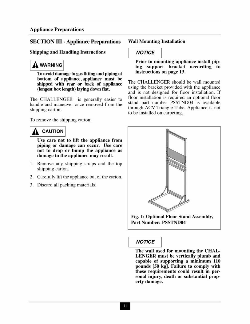
The CHALLENGER should be wall mountedusing the bracket provided with the applianceand is not designed for floor installation. Iffloor installation is required an optional floorstand part number PSSTND04 is availablethrough ACV-Triangle Tube. Appliance is notto be installed on carpeting.
The wall used for mounting the CHAL-LENGER must be vertically plumb andcapable of supporting a minimum 110pounds [50 kg]. Failure to comply withthese requirements could result in per-sonal injury, death or substantial prop-erty damage.
NOTICE
CAUTION
NOTICE
WARNING
Fig. 1: Optional Floor Stand Assembly,Part Number: PSSTND04
12
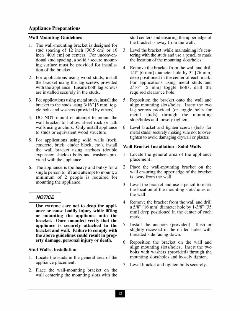
Appliance PreparationsWall Mounting Guidelines1. The wall-mounting bracket is designed for
stud spacing of 12 inch [30.5 cm] or 16inch [40.6 cm] on centers. For unconven-tional stud spacing, a solid / secure mount-ing surface must be provided for installa-tion of the bracket.
2. For applications using wood studs, installthe bracket using the lag screws providedwith the appliance. Ensure both lag screwsare installed securely in the studs.
3. For applications using metal studs, install thebracket to the studs using 3/16” [5 mm] tog-gle bolts and washers (provided by others)
4. DO NOT mount or attempt to mount thewall bracket to hollow sheet rock or lathwalls using anchors. Only install applianceto studs or equivalent wood structure.
5. For applications using solid walls (rock,concrete, brick, cinder block, etc.), installthe wall bracket using anchors (doubleexpansion shields) bolts and washers pro-vided with the appliance.
6. The appliance is too heavy and bulky for asingle person to lift and attempt to mount; aminimum of 2 people is required formounting the appliance.
Use extreme care not to drop the appli-ance or cause bodily injury while liftingor mounting the appliance onto thebracket. Once mounted verify that theappliance is securely attached to thebracket and wall. Failure to comply withthe above guidelines could result in prop-erty damage, personal injury or death.
Stud Walls -Installation 1. Locate the studs in the general area of the
appliance placement.2. Place the wall-mounting bracket on the
wall centering the mounting slots with the
stud centers and ensuring the upper edge ofthe bracket is away from the wall.
3. Level the bracket, while maintaining it’s cen-tering with the studs and use a pencil to markthe location of the mounting slots/holes.
4. Remove the bracket from the wall and drill1/4” [6 mm] diameter hole by 3” [76 mm]deep positioned in the center of each mark.For applications using metal studs and3/16” [5 mm] toggle bolts, drill therequired clearance hole.
5. Reposition the bracket onto the wall andalign mounting slots/holes. Insert the twolag screws provided (or toggle bolts formetal studs) through the mountingslots/holes and loosely tighten.
6. Level bracket and tighten screws (bolts formetal studs) securely making sure not to over-tighten to avoid damaging drywall or plaster.
Wall Bracket Installation - Solid Walls1. Locate the general area of the appliance
placement.2. Place the wall-mounting bracket on the
wall ensuring the upper edge of the bracketis away from the wall.
3. Level the bracket and use a pencil to markthe location of the mounting slots/holes onthe wall.
4. Remove the bracket from the wall and drilla 5/8” [16 mm] diameter hole by 1-3/8” [35mm] deep positioned in the center of eachmark.
5. Install the anchors (provided) flush orslightly recessed in the drilled holes withthreaded side facing down.
6. Reposition the bracket on the wall andalign mounting slots/holes. Insert the twobolts with washers (provided) through themounting slots/holes and loosely tighten.
7. Level bracket and tighten bolts securely.
NOTICE
13
Appliance Preparations
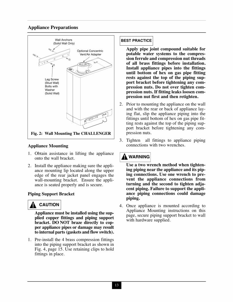
Appliance Mounting1. Obtain assistance in lifting the appliance
onto the wall bracket.2. Install the appliance making sure the appli-
ance mounting lip located along the upperedge of the rear jacket panel engages thewall-mounting bracket. Ensure the appli-ance is seated properly and is secure.
Piping Support Bracket
Appliance must be installed using the sup-plied copper fittings and piping supportbracket. DO NOT braze directly to cop-per appliance pipes or damage may resultto internal parts (gaskets and flow switch).
1. Pre-install the 4 brass compression fittingsinto the piping support bracket as shown inFig. 4, page 15. Use retaining clips to holdfittings in place.
Apply pipe joint compound suitable forpotable water systems to the compres-sion ferrule and compression nut threadsof all brass fittings before installation.Install appliance pipes into the fittingsuntil bottom of hex on gas pipe fittingrests against the top of the piping sup-port bracket before tightening any com-pression nuts. Do not over tighten com-pression nuts. If fitting leaks loosen com-pression nut first and then retighten.
2. Prior to mounting the appliance on the walland with the rear or back of appliance lay-ing flat, slip the appliance piping into thefittings until bottom of hex on gas pipe fit-ting rests against the top of the piping sup-port bracket before tightening any com-pression nuts.
3. Tighten all fittings to appliance pipingconnections with two wrenches.
Use a two wrench method when tighten-ing piping near the appliance and its pip-ing connections. Use one wrench to pre-vent the appliance connections fromturning and the second to tighten adja-cent piping. Failure to support the appli-ance piping connections could damagepiping.
4. Once appliance is mounted according toAppliance Mounting instructions on thispage, secure piping support bracket to wallwith hardware supplied.
BEST PRACTICE
CAUTION
WARNING
Lag Screw(Stud Wall)Bolts with Washer(Solid Wall)
Wall Anchors (Solid Wall Only)
Optional Concentric Vent/Air Adapter
Fig. 2: Wall Mounting The CHALLENGER
14
Boiler PipingSECTION IV - Boiler PipingGeneral Piping Requirements- All plumbing must meet or exceed all local,
state and national plumbing codes.- Support all piping using hangers. DO NOT
support piping by the appliance or its com-ponents.
- Use isolation valves to isolate system com-ponents.
- Install unions for easy removal of theCHALLENGER from the system piping.
Use a two wrench method when tighten-ing piping onto the appliance connec-tions. Use one wrench to prevent theappliance piping from turning / twisting.Failure to support the appliance pipingand connections in this manner couldcause damage to the appliance and itscomponents.
Pressure Relief Valve (PRV)1. The CHALLENGER has a ASME
Maximum Allowable Working Pressure of43.5 PSI [3 bar]. The appliance is suppliedwith a 30 psi [2 bar] pressure relief valveand must be piped using the PRV connec-tion as shown in Fig. 3 page 15.
2. To avoid potential water damage to the sur-rounding area or potential scalding hazarddue to the operation of the relief valve, thedischarge piping:- Must be connected to the discharge out-
let of the relief valve and directed to asafe place of disposal.
- Length should be as short and direct aspossible. The size of the discharge lineshould not be reduced, maintain thesame size as the outlet of the relief valve.
- Should be directed downward towardsthe floor at all times. The piping shouldterminate at least 6 inches [153 mm]
above any drain connection to allowclear visibility of the discharge.
- Should terminate with a plain end, notwith a threaded end. The material of thepiping should have a serviceable temper-ature rating of 250ºF [121ºC] or greater.
- Should not be subject to conditionswhere freezing could occur.
- Should not contain any shut-off valvesor obstructions. No shut-off valveshould be piped between the applianceand relief valve.
Failure to comply with the guidelines oninstalling the pressure relief valve and dis-charge piping can result in personal injury,death or substantial property damage.
Low Water Cut Off / CH Pressure Sensor
The Low Water Cut Off (LWCO) onlyapplies for space heating. Operation ofthe LWCO does not prevent a domestichot water call for heat.
- The CHALLENGER is equipped with a fac-tory installed pressure sensor type LWCO.
- The minimum operating Central Heating(CH) system pressure is 7 psig [0.5 bar].
- If CH System pressure is below 7 psig [0.5bar] the main display will flash a soft lockoutof “LOP” followed by the pressure reading.Once CH system pressure is increased above7 psi [0.5 bar] normal boiler operation will berestored. If the appliance is installed as domes-tic hot water heater only, set parameter 1(installation type) to 2 (domestic only) toeliminate the “LOP” error in the main display,see page 52 for setting parameters.
- Check local codes if a LWCO is required. Ifso, determine if this device meets theirrequirements.
WARNINGWARNING
NOTICE
15
Boiler Piping
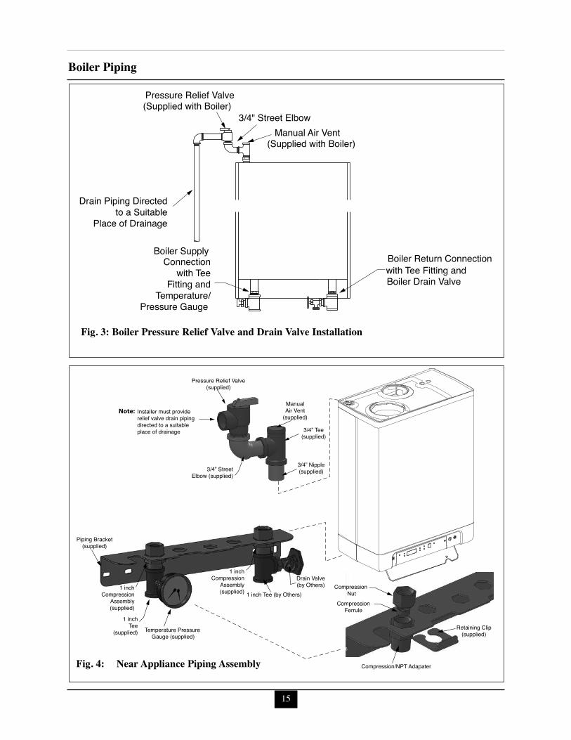
Boiler Return Connection with Tee Fitting and Boiler Drain Valve
Boiler Supply Connection
with TeeFitting and
Temperature/Pressure Gauge
Pressure Relief Valve (Supplied with Boiler)
3/4" Street Elbow Manual Air Vent
(Supplied with Boiler)
Drain Piping Directed to a Suitable
Place of Drainage
Fig. 3: Boiler Pressure Relief Valve and Drain Valve Installation
Drain Valve(by Others)1 inch
CompressionAssembly(supplied)
1 inchCompression
Assembly(supplied) 1 inch Tee (by Others)
1 inchTee
(supplied) Temperature Pressure Gauge (supplied)
Piping Bracket(supplied)
Retaining Clip(supplied)
CompressionFerrule
Compression Nut
Compression/NPT Adapater
ManualAir Vent
(supplied)
3/4” Tee(supplied)
3/4” Nipple(supplied)3/4” Street
Elbow (supplied)
Installer must providerelief valve drain pipingdirected to a suitable place of drainage
Pressure Relief Valve(supplied)
Note:
Fig. 4: Near Appliance Piping Assembly

16
Boiler PipingAdditional Limit Control
If a Low Water Cut Off (LWCO) is required bycertain local jurisdictions or when the boiler isinstalled above the system piping, the follow-ing guidelines must be followed:
- The LWCO must be designed for waterinstallations, electrode probe-type isrecommended.
- The LWCO must be installed in a teeconnection on the boiler supply pipingabove the appliance.
- Wiring of the LWCO to the CHAL-LENGER should be done in series withthe 120 VAC service to the appliance .
If the installation is to comply with ASMECSD-1 or Canadian requirements, an addition-al high temperature limit may be needed.Consult local code requirements to determinecompliance. The limit should be installed asfollows:
- Install the limit in the boiler supply pip-ing between the boiler and any isolationvalve.
- Maximum set point for the limit is200ºF [93ºC].
- Wiring of the limit device to the CHAL-LENGER should be done in series withthe 120 VAC service to the appliance.
Backflow Preventer- Use a backflow preventer valve in the
make-up water supply to the applianceas required by local codes.
Boiler System Piping Applications
It is required on all piping applicationsto utilize a primary/secondary pipingarrangement. Maintain the minimumboiler flow rate, see Graphs 5-10 onpages 79-81.
Expansion Tank and Makeup WaterEnsure the expansion tank is properly sized forthe boiler water volume (approximately 1 gal-lon [4 L]) and the system water volume andtemperature.
Undersized expansion tanks will causesystem water to be lost through the pres-sure relief valve and cause additionalmakeup water to be added to the system.Eventual boiler heat exchanger failurecan result due to this excessive makeupwater addition.
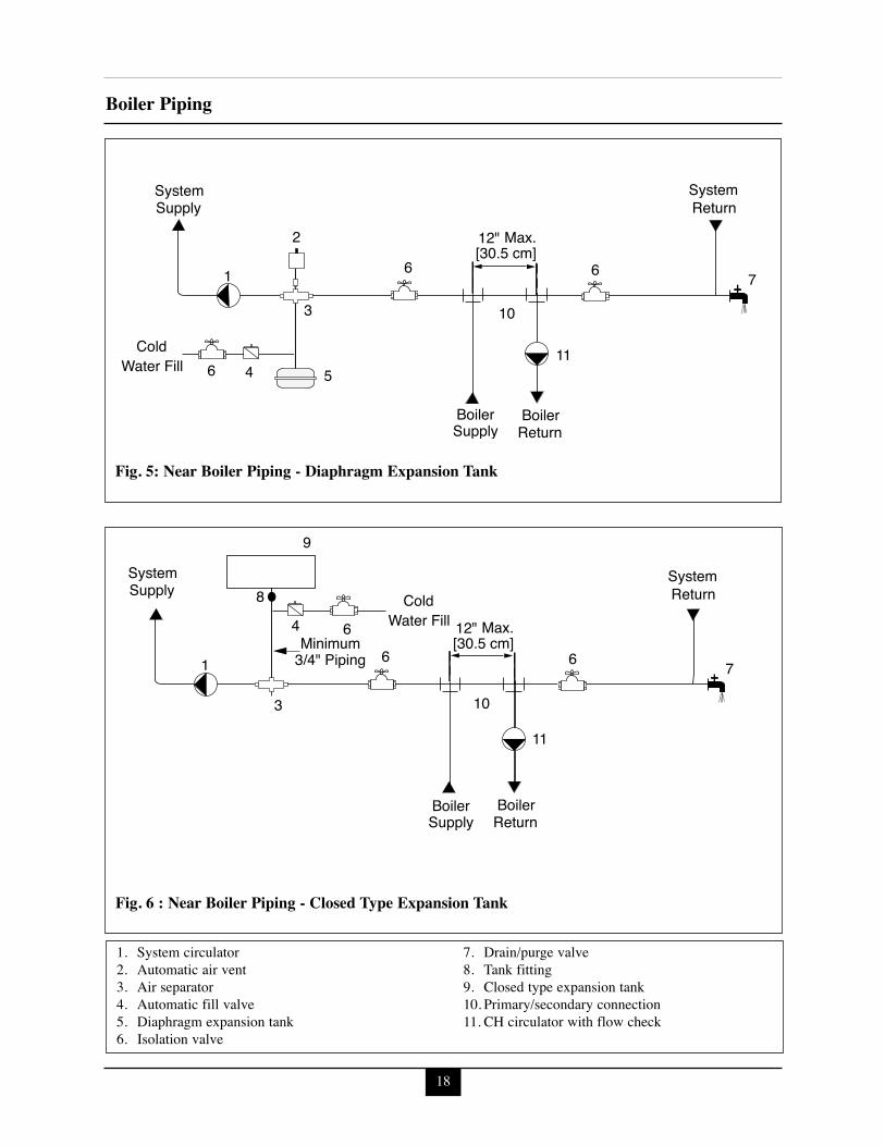
The expansion tank must be located as shownin Fig. 5 and Fig. 6 on page 18 when using aprimary/secondary piping arrangement or asper recognized design methods. Refer to theexpansion tank manufacturer instructions foradditional installation details.
Connect the expansion tank to an air separatoronly if the air separator is located on the suc-tion side (inlet) of the system circulator.Always locate and install the system fill con-nection at the same location as the expansiontank connection to the system.
Diaphragm Expansion TankAlways install an automatic air vent on the topof the air separator to remove residual air fromthe system.
BEST PRACTICE
CAUTION
17
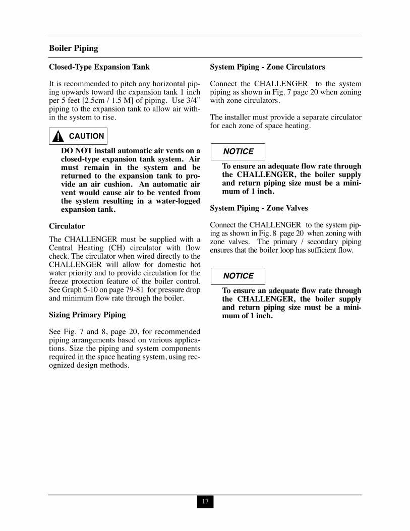
Boiler PipingClosed-Type Expansion TankIt is recommended to pitch any horizontal pip-ing upwards toward the expansion tank 1 inchper 5 feet [2.5cm / 1.5 M] of piping. Use 3/4”piping to the expansion tank to allow air with-in the system to rise.
DO NOT install automatic air vents on aclosed-type expansion tank system. Airmust remain in the system and bereturned to the expansion tank to pro-vide an air cushion. An automatic airvent would cause air to be vented fromthe system resulting in a water-loggedexpansion tank.
CirculatorThe CHALLENGER must be supplied with aCentral Heating (CH) circulator with flowcheck. The circulator when wired directly to theCHALLENGER will allow for domestic hotwater priority and to provide circulation for thefreeze protection feature of the boiler control.See Graph 5-10 on page 79-81 for pressure dropand minimum flow rate through the boiler.
Sizing Primary PipingSee Fig. 7 and 8, page 20, for recommendedpiping arrangements based on various applica-tions. Size the piping and system componentsrequired in the space heating system, using rec-ognized design methods.
System Piping - Zone CirculatorsConnect the CHALLENGER to the systempiping as shown in Fig. 7 page 20 when zoningwith zone circulators.
The installer must provide a separate circulatorfor each zone of space heating.
To ensure an adequate flow rate throughthe CHALLENGER, the boiler supplyand return piping size must be a mini-mum of 1 inch.
System Piping - Zone ValvesConnect the CHALLENGER to the system pip-ing as shown in Fig. 8 page 20 when zoning withzone valves. The primary / secondary pipingensures that the boiler loop has sufficient flow.
To ensure an adequate flow rate throughthe CHALLENGER, the boiler supplyand return piping size must be a mini-mum of 1 inch.
CAUTIONNOTICE
NOTICE
18
Boiler Piping
Max.12"
Boiler
Supply System
Return System
[30.5 cm]
Cold Water Fill
Boiler Supply Return
7
10
1
2
3
5 4 6
6 6
11
7 1
10
9
8 4
3
6
6 6
Cold Water Fill
Boiler Supply
Minimum 3/4" Piping
Boiler Return
Return System
Supply System
11
Max.12" [30.5 cm]
Fig. 6 : Near Boiler Piping - Closed Type Expansion Tank
Fig. 5: Near Boiler Piping - Diaphragm Expansion Tank
1. System circulator2. Automatic air vent3. Air separator4. Automatic fill valve5. Diaphragm expansion tank6. Isolation valve
7. Drain/purge valve8. Tank fitting9. Closed type expansion tank10. Primary/secondary connection 11. CH circulator with flow check
19
Boiler Piping
System Piping - Radiant Heating The heat exchanger design of the CHAL-LENGER allows operation in a condensingmode. This feature requires no regulation ofthe return water temperature back to the boilerin radiant heating applications.
The maximum boiler water supply temperaturecan be maintained by the CHALLENGER,potentially eliminating the need for a mixingsystem to achieve the desired temperature if allzones of heat are at the same temperature setpoint.
Size the system piping and circulator to providethe flow needed for the radiant system.
To ensure an adequate flow rate throughthe CHALLENGER, the boiler supplyand return piping size must be a mini-mum of 1 inch.
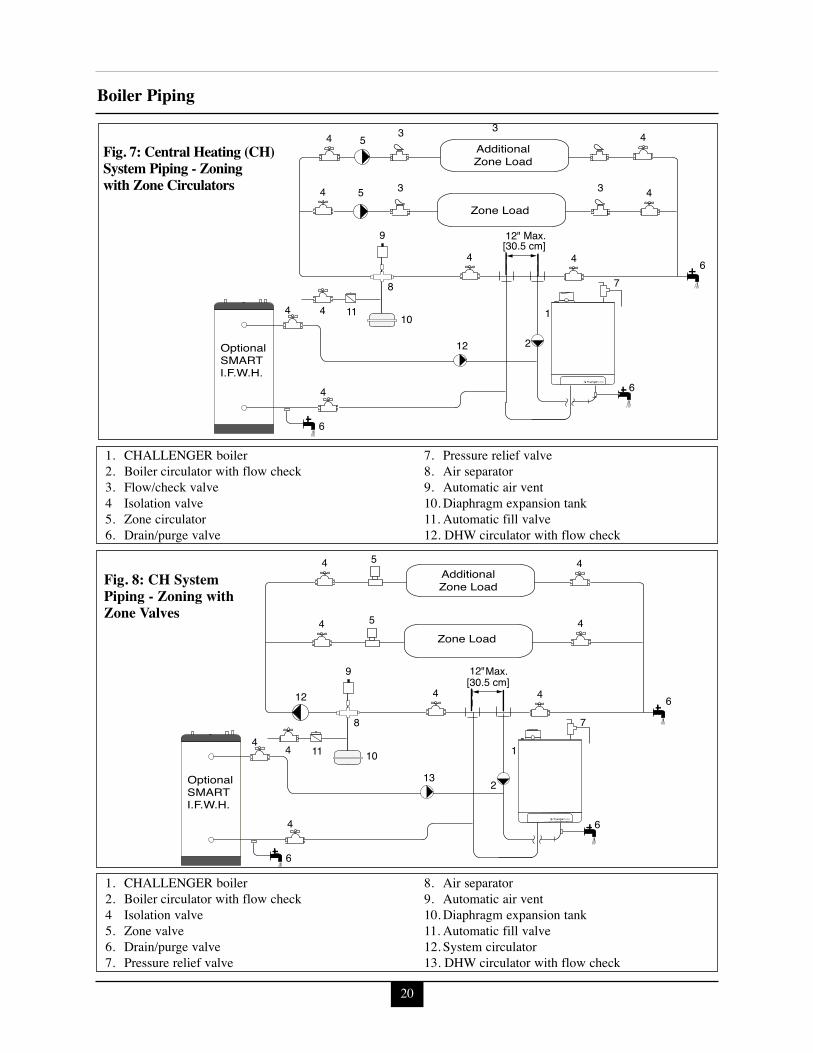
System Piping - SMART Indirect FiredWater Heater (I.F.W.H.)See Figs. 7 and 8, page 20 for recommended pip-ing for a ACV-Triangle Tube SMART I.F.W.H..This application will provide higher domestichot water flow rates for a short period of time(dump load) and will recover the SMART tankfaster than a domestic storage tank. TheSMART’s boiler piping should be piped off theprimary loop.
The boiler system piping must be a“closed” system to avoid any oxygencontamination and potential failure ofthe outer tank of the SMART.
The CHALLENGER’s domestic piping shouldnot be utilized. Refer to the installation manualprovided with the SMART for additional instal-lation details.
See Parameter 1 and Note 3, page 52 for parame-ter, wiring and operational details using theSMART I.F.W.H. with a CHALLENGER boiler.
System Piping - Special ApplicationIf the boiler is used in conjunction with achilled water/medium system, the boiler andchiller must be piped in parallel. Installflow/check valves to prevent the chilled medi-um from entering the boiler.
If the boiler is used to supply hot water to theheating coils of an air handler where they maybe exposed to chilled air circulation, installflow/check valves or other automatic devicesto prevent gravity circulation of the boilerwater during cooling cycles.
NOTICE
NOTICE
20
Boiler Piping
2
6
5
5
4
6 12
9
8
1011
4
4
4
4
4 4
7
Additional
Max.[30.5 cm]12"
Zone Load
1
Zone Load
13
6
4
4
OptionalSMART I.F.W.H.
5
5
4
6
212
3
3
3
3
[30.5 cm]9
8
1011
4
4
4
4
44
Zone Load
Additional
7
6
6
Max.12"
Zone Load
1
4
4
OptionalSMART I.F.W.H.
Fig. 7: Central Heating (CH)System Piping - Zoningwith Zone Circulators
1. CHALLENGER boiler2. Boiler circulator with flow check3. Flow/check valve4 Isolation valve5. Zone circulator 6. Drain/purge valve
7. Pressure relief valve8. Air separator9. Automatic air vent10. Diaphragm expansion tank11. Automatic fill valve12. DHW circulator with flow check
Fig. 8: CH SystemPiping - Zoning withZone Valves
1. CHALLENGER boiler2. Boiler circulator with flow check4 Isolation valve5. Zone valve6. Drain/purge valve7. Pressure relief valve
8. Air separator9. Automatic air vent10. Diaphragm expansion tank11. Automatic fill valve12. System circulator13. DHW circulator with flow check
Domestic Piping
SECTION V - Domestic Piping
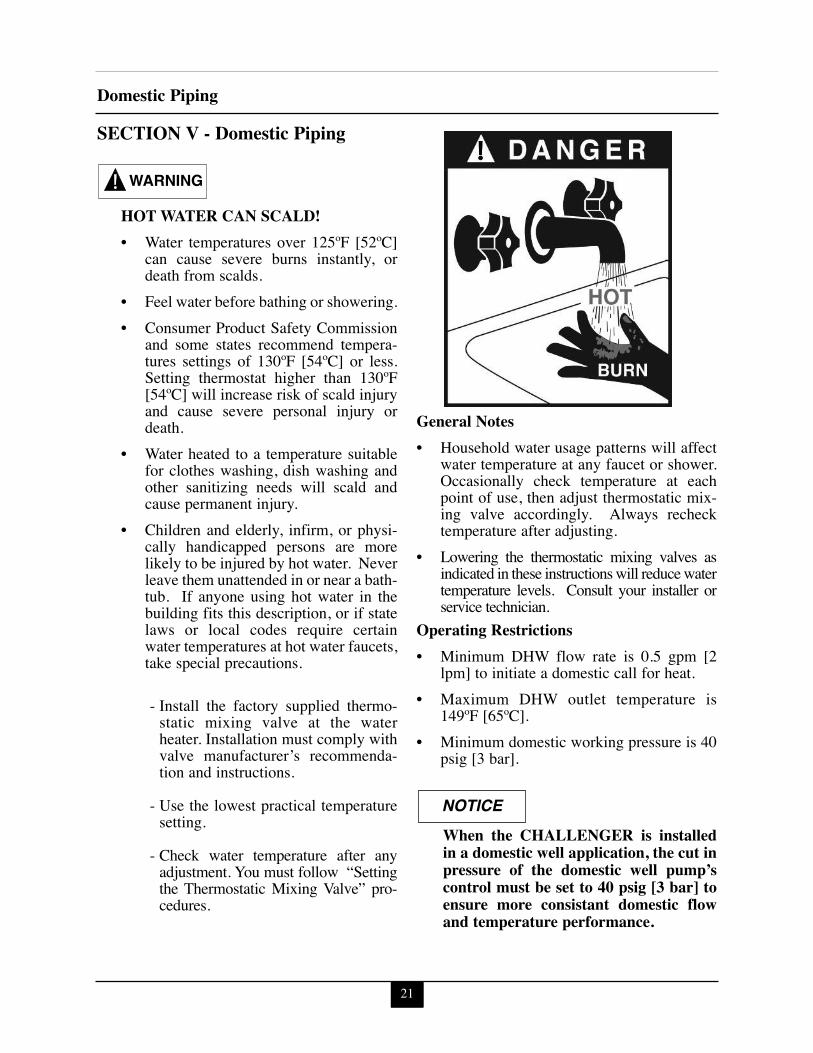
HOT WATER CAN SCALD!• Water temperatures over 125ºF [52ºC]
can cause severe burns instantly, ordeath from scalds.
• Feel water before bathing or showering.• Consumer Product Safety Commission
and some states recommend tempera-tures settings of 130ºF [54ºC] or less.Setting thermostat higher than 130ºF[54ºC] will increase risk of scald injuryand cause severe personal injury ordeath.
• Water heated to a temperature suitablefor clothes washing, dish washing andother sanitizing needs will scald andcause permanent injury.
• Children and elderly, infirm, or physi-cally handicapped persons are morelikely to be injured by hot water. Neverleave them unattended in or near a bath-tub. If anyone using hot water in thebuilding fits this description, or if statelaws or local codes require certainwater temperatures at hot water faucets,take special precautions.
- Install the factory supplied thermo-static mixing valve at the waterheater. Installation must comply withvalve manufacturer’s recommenda-tion and instructions.
- Use the lowest practical temperaturesetting.
- Check water temperature after anyadjustment. You must follow “Settingthe Thermostatic Mixing Valve” pro-cedures.
General Notes• Household water usage patterns will affect
water temperature at any faucet or shower.Occasionally check temperature at eachpoint of use, then adjust thermostatic mix-ing valve accordingly. Always rechecktemperature after adjusting.
• Lowering the thermostatic mixing valves asindicated in these instructions will reduce watertemperature levels. Consult your installer orservice technician.
Operating Restrictions• Minimum DHW flow rate is 0.5 gpm [2
lpm] to initiate a domestic call for heat.• Maximum DHW outlet temperature is
149ºF [65ºC].• Minimum domestic working pressure is 40
psig [3 bar].
When the CHALLENGER is installedin a domestic well application, the cut inpressure of the domestic well pump’scontrol must be set to 40 psig [3 bar] toensure more consistant domestic flowand temperature performance.
WARNING
NOTICE
21
• Maximum domestic working pressure is150 psig [10 bar].
• Water quality limitations (based on E.P.ANational Secondary Drinking WaterRegulations):- Chloride, less than 150 ppm or mg/l- pH value min. 6.5, max. 8.5- Total hardness 3 - 7 grains/gallon or 50-
120 ppm or mg/l.- Total Dissolved Solids (TDS), less than
120 ppm or mg/l.- Iron less than 0.3 ppm or mg/l.- Aluminum, less than 0.2 ppm or mg/l.- Copper, less than 1 ppm or mg/l.- Manganese, less than 0.05 ppm or mg/l.- Zinc, less than 5 ppm or mg/l.
In hard water areas (more than 7 grainsof hardness) soften the cold domesticsupply water to the appliance to preventscaling.
Any water conditioning system must beinstalled and maintained in accordancewith manufacturer’s specifications.
Pressure Relief Valve - StandardInstallations The domestic water heater (if utilized) shallhave a field supplied pressure relief valveinstalled within 6” [152 mm] of the DHW HOToutlet connection with the relief valve spindleinstalled in the vertical position.
The domestic water heater (if utilized) requiresa field supplied pressure relief valve identifiedwith the ASME V or HV symbol and set to
relieve at or below 150 psi [ 10 bar] of domes-tic water pressure and a minimum relievingcapacity of 124,000 Btu/hr with 3/4” NPTthreads. For safe operation of the domesticwater heater, the relief valve must not beremoved from its designated location of instal-lation or plugged.1. The CHALLENGER is not supplied with a
150 psi [10 bar] pressure relief valve andmust be piped using a Pressure Relief Valveconnected as shown in Fig. 11 page 26.
2. To avoid potential water damage to the sur-rounding area or potential scalding hazarddue to the operation of the relief valve, thedischarge piping:- Must be connected to the discharge out-
let of the relief valve and directed to asafe place of disposal.
- Length should be as short and direct aspossible. The size of the discharge lineshould not be reduced, maintain thesame size as the outlet of the relief valve.
- Should be directed downward towardsthe floor at all times. The piping shouldterminate at least 6 inches [152 mm]above any drain connection to allowclear visibility of the discharge.
- Should terminate with a plain end, notwith a threaded end. The material of thepiping should have a serviceable temper-ature rating of 250ºF [121ºC] or greater.
- Should not be subject to conditionswhere freezing could occur.
- Should not contain any shut-off valvesor obstructions. No shut-off valveshould be piped between the applianceand relief valve.
Failure to comply with the guidelines oninstalling the pressure relief valve and dis-charge piping can result in personal injury,death or substantial property damage.
WARNING
NOTICE
BEST PRACTICE
Domestic Piping
22
23
Domestic PipingTemperature & Pressure (T&P) Relief Valve-Storage Tank or SMART Installations
To reduce risk of excessive pressures andtemperatures in a storage tank or ACV-Triangle Tube SMART I.F.W.H., installtemperature and pressure protectiveequipment required by local codes, but noless than a combination temperature andpressure relief valve certified by a nation-ally recognized testing laboratory thatmaintains periodic inspection of produc-tion of listed equipment or materials, asmeeting the requirements for ReliefValves and Automatic Gas ShutoffDevices for Hot Water Supply Systems,ANSI Z21.22. This valve must be markedwith the maximum working pressure ofthe domestic water heater (150 psi).
• The storage tank or SMART must be pro-tected with a field supplied T&P relief valve.
• Size the T&P relief valve by the follow-ing specifications, unless they conflictwith local codes: 3/4” NPT with an AGARating of 124,000 BTU/hr.
T&P Relief Valve Discharge PipingT&P relief valve discharge piping must be:- made of material serviceable for tem-peratures of 250ºF [121ºC] or greater
- directed so that hot water flows awayfrom all persons
- directed to a suitable place for disposal- installed so as to allow complete drainingof the T&P relief valve and discharge line
T&P relief valve discharge piping MUSTNOT be:
- excessively long, using more than 2elbows or 15 feet [4.5 m] of piping canreduce discharge capacity
- directly connected to a drain, terminatedischarge piping within 6” [152 mm]from drain, refer to local codes
- plugged, reduced or restricted- subject to freezing
Do not install any valve between T&Prelief valve and the storage tank orSMART connection or on T&P reliefvalve discharge piping. Do not plugT&P relief valve or discharge piping.Improper placement and piping of T&Prelief valve can cause severe personalinjury, death or substantial propertydamage.
Isolation valves are only intended forservicing the domestic coil. During anydomestic service the appliance should beturned off and the domestic coil drainedto prevent over pressurization of theappliance’s domestic coil.
Drain ValvesDrain valves and fittings are field supplied.
Thermal ExpansionIf a backflow preventer, check valve or pressurereducing valve is installed on the cold water sup-ply piping of the domestic water heater, installan expansion tank on the cold water supply lineto prevent normal thermal expansion fromrepeatedly forcing open the relief valve.
Relief valve is not intended for constantduty, such as relief of pressure due torepeated normal system water expansion.Correct this condition by installing aproperly sized expansion tank in domes-tic water system. Refer to expansion tankmanufacturer’s installation instructionsfor proper sizing.
WARNINGCAUTION
WARNING
CAUTION
24
Domestic PipingThe domestic water volume of theCHALLENGER is approximately 0.26gallons [ 1 l]. Remember to include thisvolume when sizing the expansion tank.
Water HammerDishwashers, clothes washers and fast-closingpositive shut-off valves incorporated in the sys-tem all contribute to creating water shock. Installa water hammer arrester to prevent damage topipes and appliances. See device manufacturer’sinstructions for application and installation.
Vacuum Breaker - Storage Tank or SMARTInstallationsInstalling a vacuum breaker on the inlet of the stor-age tank will prevent damage to the tank if a nega-tive pressure is developed in the domestic supplyline. See manufacturer’s instructions for applica-tion and installation of the vacuum breaker.
General Piping Requirements• For domestic water piping diagrams, see
Figs 11 and 12, pages 26 and 27.
It is recommended to install flush valvesas outlined in Fig. 11 and 12, pages 26and 27 for servicing the domestic coil.
It is recommended to install a strainer onthe domestic cold water inlet to preventany nuisance issues with domestic flowswitch. An optional lead free, 60 mesh y-strainer is available through ACV-TriangleTube part number CCSTRA01.
• All plumbing must meet or exceed all local,state and national plumbing codes.
• Use pipe joint compound or tape suitablefor potable water systems.
• Size all piping no smaller than the appli-ance’s DHW connections.
• Use isolation valves to isolate the DHWconnections and system components.
• Use dielectric unions or couplings to pro-tect hot and cold water fittings from corro-sion when connecting dissimilar materialssuch as copper and galvanized iron pipe.
• If copper pipe is used for domestic waterconnections, first solder pipe to a threadedadapter and then screw adapter onto thedomestic cold water inlet of the appliance.The domestic cold water inlet contains aninternal plastic flow switch which can bedamaged by heat from soldering.
Do not apply heat to the domestic coldwater inlet when making solder connec-tions to water heater. Solder tubing toadapter before fitting adapter to coldwater inlet of heater. It is imperative thatno heat be applied to the cold water inlet,as it contains a non metallic flow switch.
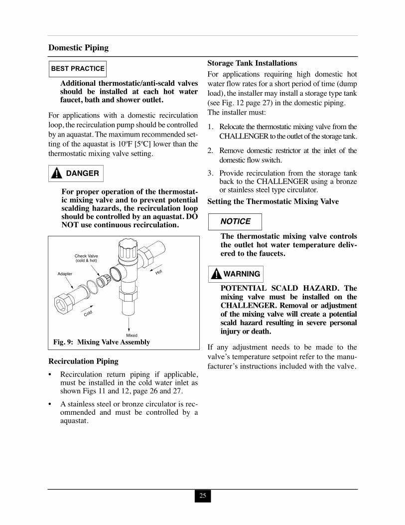
Thermostatic Mixing ValveThe CHALLENGER is factory supplied with athermostatic mixing valve with built-in checkvalves on the hot and cold inlets. The mixing valvemust be installed as shown in Figs. 9, 11 and 12.
The mixing water temperature range of thethermostatic mixing valve is 85ºF [30ºC] to140ºF [60ºC].
The thermostatic mixing valve is preset to its min-imum mixed water temperature, 85ºF [30ºC].
BEST PRACTICE
BEST PRACTICE
NOTICE
25
Domestic Piping
Additional thermostatic/anti-scald valvesshould be installed at each hot waterfaucet, bath and shower outlet.
For applications with a domestic recirculationloop, the recirculation pump should be controlledby an aquastat. The maximum recommended set-ting of the aquastat is 10ºF [5ºC] lower than thethermostatic mixing valve setting.
For proper operation of the thermostat-ic mixing valve and to prevent potentialscalding hazards, the recirculation loopshould be controlled by an aquastat. DONOT use continuous recirculation.
Recirculation Piping• Recirculation return piping if applicable,
must be installed in the cold water inlet asshown Figs 11 and 12, page 26 and 27.
• A stainless steel or bronze circulator is rec-ommended and must be controlled by aaquastat.
Storage Tank InstallationsFor applications requiring high domestic hotwater flow rates for a short period of time (dumpload), the installer may install a storage type tank(see Fig. 12 page 27) in the domestic piping.The installer must:
1. Relocate the thermostatic mixing valve from theCHALLENGER to the outlet of the storage tank.
2. Remove domestic restrictor at the inlet of thedomestic flow switch.
3. Provide recirculation from the storage tankback to the CHALLENGER using a bronzeor stainless steel type circulator.
Setting the Thermostatic Mixing Valve
The thermostatic mixing valve controlsthe outlet hot water temperature deliv-ered to the faucets.
POTENTIAL SCALD HAZARD. Themixing valve must be installed on theCHALLENGER. Removal or adjustmentof the mixing valve will create a potentialscald hazard resulting in severe personalinjury or death.
If any adjustment needs to be made to thevalve’s temperature setpoint refer to the manu-facturer’s instructions included with the valve.
NOTICE
WARNING
DANGER
BEST PRACTICE
Cold
Hot Adapter
Check Valve(cold & hot)
Mixed Fig. 9: Mixing Valve Assembly
26
Domestic Piping
6
To Dish Washeror High Temperature
Application
6
M
cH
1
5
ColdDHW
Water Inlet
410
9 3 2
2 2
7
8
Recir
culat
ingLo
op(o
ption
al)
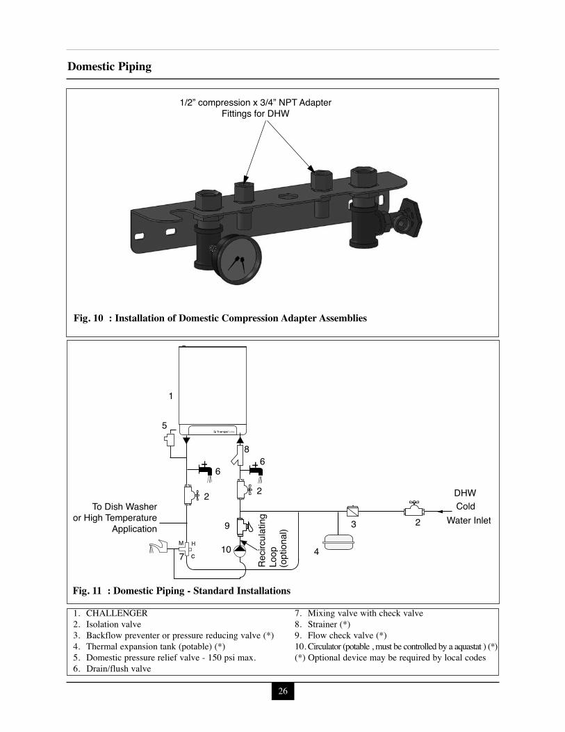
Fig. 11 : Domestic Piping - Standard Installations
1. CHALLENGER2. Isolation valve 3. Backflow preventer or pressure reducing valve (*)4. Thermal expansion tank (potable) (*)5. Domestic pressure relief valve - 150 psi max.6. Drain/flush valve
7. Mixing valve with check valve8. Strainer (*)9. Flow check valve (*)10. Circulator (potable , must be controlled by a aquastat ) (*)(*) Optional device may be required by local codes
1/2” compression x 3/4” NPT AdapterFittings for DHW
Fig. 10 : Installation of Domestic Compression Adapter Assemblies

27
Domestic Piping
StorageTank
5
RecirculatingLoop (optional)
Remove anycheck valve 11
1
For service only see warning onpage 23
912
DHWColdWater Inlet
8 9
7
3
10
4
2
2
M
H
C
66
6
2
2
Fig. 12 : Domestic Piping - Storage Tank Installations
1. CHALLENGER 2. Isolation valve 3. Backflow preventer or pressure reducing valve (*)4. Thermal expansion tank (potable) (*)5. Temperature/Pressure relief valve6. Drain/flush valve7. Mixing valve with check valve8. Circulator (potable, must be controlled by a aquastat) (*)9. Flow check valve
10. Strainer (*)11. Vacuum breaker (*)12. Domestic circulator (potable Grundfos UP26-99BF
or Taco 009-SF5 or equivalent sized for 2.5 gpm[9.5 lpm] at 32 feet [9.7 m], must be controlled bya aquastat mounted on the storage tank with a max-imum set point of 130ºF [55ºC].
(*) Optional device maybe required by local codes
Note:Domestic cold water inlet through a storage tank will yield a lower domestic pressure drop in addition togreater domestic performance. Domestic set point temperature should be set to 149ºF [65ºC] see page 52. DHWfunction button ( ) should be set to ON ( ) at the display panel, see page 49. Remove domesticrestrictor at inlet of the domestic flow switch.
Installation Vent/Combustion Air & Condensate Drain
28
SECTION VI - Installing Vent /Combustion Air & Condensate DrainInstalling Vent and Combustion Air
The CHALLENGER must be ventedand supplied with combustion air asshown in the CHALLENGER PVC,CPVC, PP and SS Vent Supplement2013-38, included in the installationenvelope. Refer to instructions for partslist and method of installation. Onceinstallation is completed, inspect the ventand combustion air system thoroughly toensure systems are airtight and complywith the instructions given in the ventingsupplement and are within all require-ments of applicable codes. Failure tocomply with the installation require-ments on the venting and combustion airpiping will cause severe personal injuryor death.
Contact ACV-Triangle Tube for otherventing options including PVC Concen-tric Vent/Air Termination Supplement2008-04 or CHALLENGER ConcentricVent/Air System Supplement 2011-60.Refer to these instructions for parts listand method of installation.
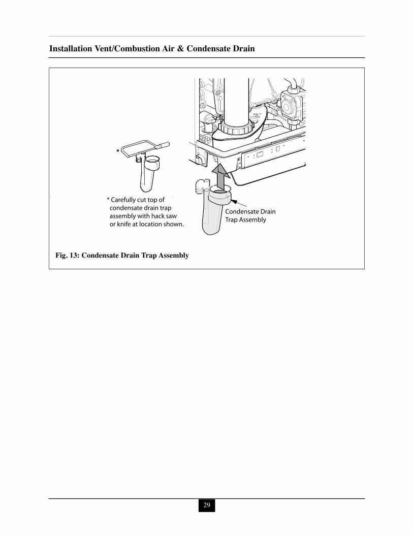
Installing Condensate Drain Assembly1. Locate the condensate trap assembly and
cut top with hacksaw or knife and install asshown in Fig. 13 page 29.
The installer must fill the condensatetrap with water prior to assembling onthe appliance. Do not operate appliancewithout factory supplied condensatetrap installed on appliance.
2. Remove front door and install trap. Ensurethe trap is completely seated and secure onthe appliance.
3. Connect 13/16” ID tubing to the drainbarbed fitting of the trap assembly.
The drain line materials must be anapproved material by the authority hav-ing jurisdiction. In absence of suchauthority, PVC and CPVC piping mustcomply with ASTM D1785 or D2845.The cement and primer used on the pip-ing must comply with ASME D2564 orF493. For installations in Canada, useULC certified PVC or CPVC pipe, fit-tings and cement/primer.
4. Continue the tubing from the trap assemblyto a floor drain or condensate pump.
When selecting and installing a conden-sate pump, ensure the pump is approvedfor use with condensing appliances. Thepump should be equipped with an over-flow switch to prevent property damagefrom potential condensate spillage.
5. The CHALLENGER will typically producea condensate that is considered slightlyacidic with a pH content below 4.0. Installa neutralizing filter if required.
The condensate drain must remainfilled, unobstructed and allow unre-stricted flow of condensate. The conden-sate should not be subject to conditionswhere freezing could occur. If the con-densate is subjected to freezing orbecomes obstructed , it can leak, result-ing in potential water damage to theappliance and surrounding area.
NOTICE
NOTICE
NOTICE
CAUTION
DANGER
NOTICE
29
Installation Vent/Combustion Air & Condensate Drain
*
Condensate Drain Trap Assembly
* Carefully cut top of condensate drain trap assembly with hack saw or knife at location shown.
*
Fig. 13: Condensate Drain Trap Assembly
30
Gas PipingSECTION VII - Gas PipingGas Supply Piping Connection
The gas supply piping must be installedin accordance to all applicable local,state and national codes and utilityrequirements.
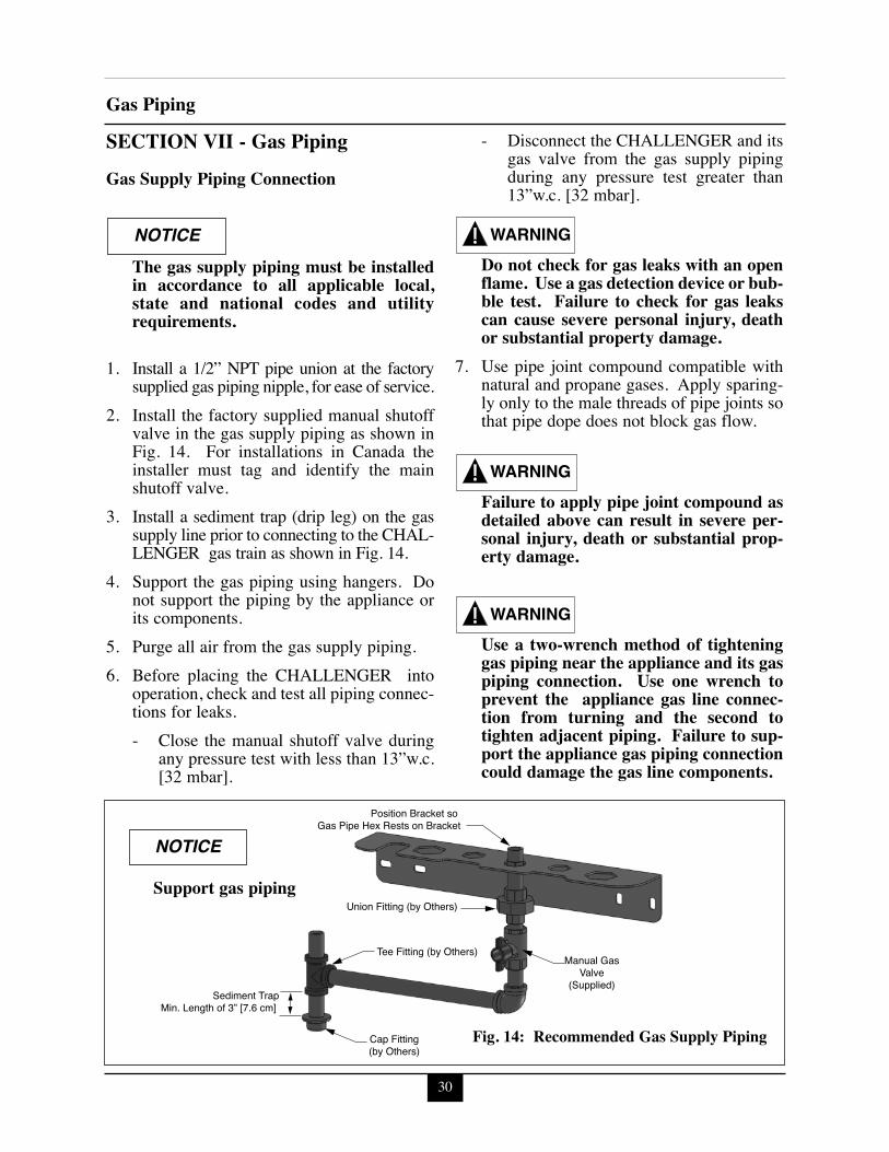
1. Install a 1/2” NPT pipe union at the factorysupplied gas piping nipple, for ease of service.
2. Install the factory supplied manual shutoffvalve in the gas supply piping as shown inFig. 14. For installations in Canada theinstaller must tag and identify the mainshutoff valve.
3. Install a sediment trap (drip leg) on the gassupply line prior to connecting to the CHAL-LENGER gas train as shown in Fig. 14.
4. Support the gas piping using hangers. Donot support the piping by the appliance orits components.
5. Purge all air from the gas supply piping.6. Before placing the CHALLENGER into
operation, check and test all piping connec-tions for leaks.- Close the manual shutoff valve during
any pressure test with less than 13”w.c.[32 mbar].
- Disconnect the CHALLENGER and itsgas valve from the gas supply pipingduring any pressure test greater than13”w.c. [32 mbar].
Do not check for gas leaks with an openflame. Use a gas detection device or bub-ble test. Failure to check for gas leakscan cause severe personal injury, deathor substantial property damage.
7. Use pipe joint compound compatible withnatural and propane gases. Apply sparing-ly only to the male threads of pipe joints sothat pipe dope does not block gas flow.
Failure to apply pipe joint compound asdetailed above can result in severe per-sonal injury, death or substantial prop-erty damage.
Use a two-wrench method of tighteninggas piping near the appliance and its gaspiping connection. Use one wrench toprevent the appliance gas line connec-tion from turning and the second totighten adjacent piping. Failure to sup-port the appliance gas piping connectioncould damage the gas line components.
WARNING
WARNING
WARNING
NOTICE
Position Bracket so Gas Pipe Hex Rests on Bracket
Tee Fitting (by Others)
Union Fitting (by Others)
Manual GasValve
(Supplied)
Cap Fitting(by Others)
Sediment TrapMin. Length of 3” [7.6 cm]
Fig. 14: Recommended Gas Supply Piping
Support gas piping
NOTICE
31
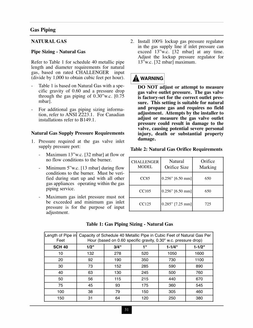
Gas PipingNATURAL GASPipe Sizing - Natural GasRefer to Table 1 for schedule 40 metallic pipelength and diameter requirements for naturalgas, based on rated CHALLENGER input(divide by 1,000 to obtain cubic feet per hour).- Table 1 is based on Natural Gas with a spe-
cific gravity of 0.60 and a pressure dropthrough the gas piping of 0.30”w.c. [0.75mbar].
- For additional gas piping sizing informa-tion, refer to ANSI Z223.1. For Canadianinstallations refer to B149.1.
Natural Gas Supply Pressure Requirements1. Pressure required at the gas valve inlet
supply pressure port:- Maximum 13”w.c. [32 mbar] at flow or
no flow conditions to the burner.- Minimum 5”w.c. [13 mbar] during flow
conditions to the burner. Must be veri-fied during start up and with all othergas appliances operating within the gaspiping service.
- Maximum gas inlet pressure must notbe exceeded and minimum gas inletpressure is for the purpose of inputadjustment.
2. Install 100% lockup gas pressure regulatorin the gas supply line if inlet pressure canexceed 13”w.c. [32 mbar] at any time.Adjust the lockup pressure regulator for13”w.c. [32 mbar] maximum.
DO NOT adjust or attempt to measuregas valve outlet pressure. The gas valveis factory-set for the correct outlet pres-sure. This setting is suitable for naturaland propane gas and requires no fieldadjustment. Attempts by the installer toadjust or measure the gas valve outletpressure could result in damage to thevalve, causing potential severe personalinjury, death or substantial propertydamage.
Table 2: Natural Gas Orifice Requirements
WARNING
Length of Pipe inFeet
Capacity of Schedule 40 Metallic Pipe in Cubic Feet of Natural Gas PerHour (based on 0.60 specific gravity, 0.30" w.c. pressure drop)
SCH 40 1/2" 3/4" 1" 1-1/4" 1-1/2"10 132 278 520 1050 160020 92 190 350 730 110030 73 152 285 590 89040 63 130 245 500 76050 56 115 215 440 67075 45 93 175 360 545100 38 79 150 305 460150 31 64 120 250 380
Table 1: Gas Piping Sizing - Natural Gas
CHALLENGER MODEL
NaturalOrifice Size
Orifice Marking
CC85 0.256” [6.50 mm] 650
CC105 0.256” [6.50 mm] 650
CC125 0.285” [7.25 mm] 725
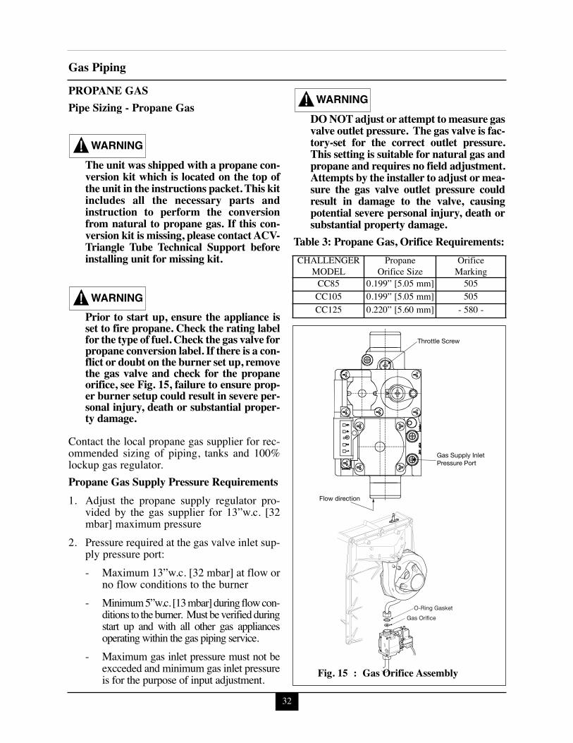
32
Gas PipingPROPANE GASPipe Sizing - Propane Gas
The unit was shipped with a propane con-version kit which is located on the top ofthe unit in the instructions packet. This kitincludes all the necessary parts andinstruction to perform the conversionfrom natural to propane gas. If this con-version kit is missing, please contact ACV-Triangle Tube Technical Support beforeinstalling unit for missing kit.
Prior to start up, ensure the appliance isset to fire propane. Check the rating labelfor the type of fuel. Check the gas valve forpropane conversion label. If there is a con-flict or doubt on the burner set up, removethe gas valve and check for the propaneorifice, see Fig. 15, failure to ensure prop-er burner setup could result in severe per-sonal injury, death or substantial proper-ty damage.
Contact the local propane gas supplier for rec-ommended sizing of piping, tanks and 100%lockup gas regulator.Propane Gas Supply Pressure Requirements1. Adjust the propane supply regulator pro-
vided by the gas supplier for 13”w.c. [32mbar] maximum pressure
2. Pressure required at the gas valve inlet sup-ply pressure port:- Maximum 13”w.c. [32 mbar] at flow or
no flow conditions to the burner- Minimum 5”w.c. [13 mbar] during flow con-
ditions to the burner. Must be verified duringstart up and with all other gas appliancesoperating within the gas piping service.
- Maximum gas inlet pressure must not beexcceded and minimum gas inlet pressureis for the purpose of input adjustment.
DO NOT adjust or attempt to measure gasvalve outlet pressure. The gas valve is fac-tory-set for the correct outlet pressure.This setting is suitable for natural gas andpropane and requires no field adjustment.Attempts by the installer to adjust or mea-sure the gas valve outlet pressure couldresult in damage to the valve, causingpotential severe personal injury, death orsubstantial property damage.
Table 3: Propane Gas, Orifice Requirements:
WARNING
WARNING
WARNING
Throttle Screw
Gas Supply Inlet Pressure Port
Flow direction
Gas Orifice
O-Ring Gasket
Fig. 15 : Gas Orifice Assembly
CHALLENGER MODEL
PropaneOrifice Size
Orifice Marking
CC85 0.199” [5.05 mm] 505CC105 0.199” [5.05 mm] 505CC125 0.220” [5.60 mm] - 580 -
33
Internal WiringSECTION VIII - Internal Wiring
ELECTRICAL SHOCK HAZARD. Foryour safety, disconnect electrical powersupply to the appliance before servicingor making any electrical connections toavoid possible electric shock hazard.Failure to do so can cause severe person-al injury or death.
Prior to servicing, label all wires beforedisconnecting. Wiring errors can causeimproper and dangerous operation.Verify proper wiring and operation afterservicing.
General Requirements- Wiring must be N.E.C Class 1.- If original wiring as supplied with the
appliance must be replaced, use only TypeT 194F [90ºC] wire or equivalent as a min-imum.
- The CHALLENGER must be electricallygrounded as required by NationalElectrical Code ANSI/NFPA 70 - latest edi-tion and / or the Canadian Electrical CodePart 1, CSA C22.1, Electrical Code.
CAUTION
WARNING
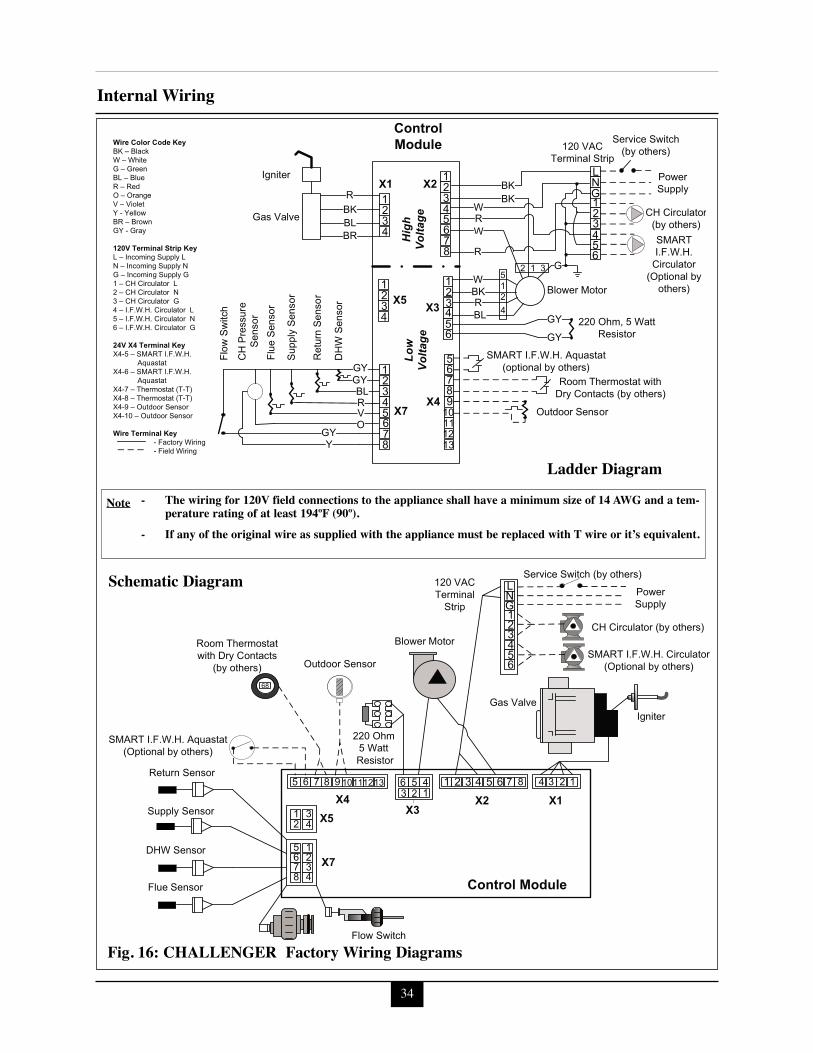
34
Internal Wiring
Fig. 16: CHALLENGER Factory Wiring Diagrams
Ladder Diagram- The wiring for 120V field connections to the appliance shall have a minimum size of 14 AWG and a tem-
perature rating of at least 194ºF (90º).- If any of the original wire as supplied with the appliance must be replaced with T wire or it’s equivalent.
Note
Schematic Diagram
35
External WiringSECTION IX- External WiringInstallation ComplianceAll field wiring made during installation mustcomply with:
- National Electrical Code NFPA 70 andany other national, state, provincial orlocal codes or requirements.
- In Canada, CSA C22.1 CanadianElectrical Code Part 1, and any otherlocal codes.
ELECTRICAL SHOCK HAZARD.Before making any electrical connec-tions to the CHALLENGER, disconnectelectrical power supply at the servicepanel. Failure to comply can causesevere personal injury or death.
Line Voltage Connections1. Connect a 120 VAC/15A service to the
120V terminals L, N and G inside theCHALLENGER as shown in Fig. 16,page 34.
2. Route the incoming 120 VAC power wirethrough the provided openings in the bot-tom right side jacket panel.
3. The appliance must be provided with anexternal service switch, check local coderequirements for compliance.
The installer must provide and install afused disconnect or 15 amp (minimum)service switch. Check local electricalcode requirements for compliance.
The ON/OFF switch of the CHAL-LENGER only disables the function of theappliance. Electrical power remains at thecontrol module. To avoid a shock hazard,disconnect power at the external serviceswitch when servicing the appliance.
Control Module Circulator AMP Ratings- AMP draw of the CH circulator must not
exceed 2.3 amps.
WARNING
NOTICE
WARNING
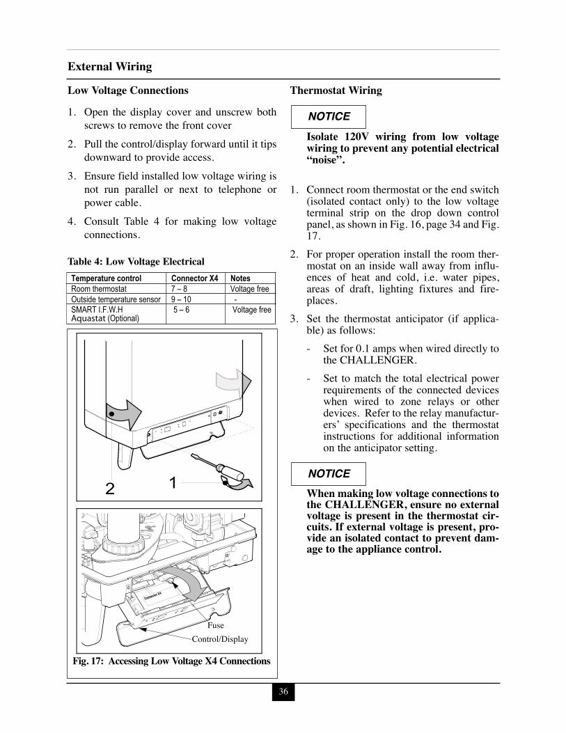
36
External WiringLow Voltage Connections1. Open the display cover and unscrew both
screws to remove the front cover2. Pull the control/display forward until it tips
downward to provide access.3. Ensure field installed low voltage wiring is
not run parallel or next to telephone orpower cable.
4. Consult Table 4 for making low voltageconnections.
Table 4: Low Voltage Electrical
Thermostat Wiring
Isolate 120V wiring from low voltagewiring to prevent any potential electrical“noise”.
1. Connect room thermostat or the end switch(isolated contact only) to the low voltageterminal strip on the drop down controlpanel, as shown in Fig. 16, page 34 and Fig.17.
2. For proper operation install the room ther-mostat on an inside wall away from influ-ences of heat and cold, i.e. water pipes,areas of draft, lighting fixtures and fire-places.
3. Set the thermostat anticipator (if applica-ble) as follows:- Set for 0.1 amps when wired directly to
the CHALLENGER.- Set to match the total electrical power
requirements of the connected deviceswhen wired to zone relays or otherdevices. Refer to the relay manufactur-ers’ specifications and the thermostatinstructions for additional informationon the anticipator setting.
When making low voltage connections tothe CHALLENGER, ensure no externalvoltage is present in the thermostat cir-cuits. If external voltage is present, pro-vide an isolated contact to prevent dam-age to the appliance control.
NOTICE
NOTICE
FuseControl/Display
Fig. 17: Accessing Low Voltage X4 Connections
Temperature control Connector X4 Notes Room thermostat 7 – 8 Voltage free Outside temperature sensor 9 – 10 -
SMART I.F.W.H 5 – 6 Voltage free Aquastat (Optional)
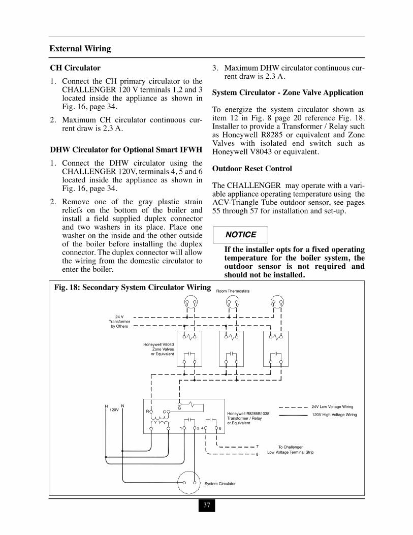
37
External Wiring
CH Circulator1. Connect the CH primary circulator to the
CHALLENGER 120 V terminals 1,2 and 3located inside the appliance as shown inFig. 16, page 34.
2. Maximum CH circulator continuous cur-rent draw is 2.3 A.
DHW Circulator for Optional Smart IFWH1. Connect the DHW circulator using the
CHALLENGER 120V, terminals 4, 5 and 6located inside the appliance as shown inFig. 16, page 34.
2. Remove one of the gray plastic strainreliefs on the bottom of the boiler andinstall a field supplied duplex connectorand two washers in its place. Place onewasher on the inside and the other outsideof the boiler before installing the duplexconnector. The duplex connector will allowthe wiring from the domestic circulator toenter the boiler.
3. Maximum DHW circulator continuous cur-rent draw is 2.3 A.
System Circulator - Zone Valve ApplicationTo energize the system circulator shown asitem 12 in Fig. 8 page 20 reference Fig. 18.Installer to provide a Transformer / Relay suchas Honeywell R8285 or equivalent and ZoneValves with isolated end switch such asHoneywell V8043 or equivalent.
Outdoor Reset ControlThe CHALLENGER may operate with a vari-able appliance operating temperature using theACV-Triangle Tube outdoor sensor, see pages55 through 57 for installation and set-up.
If the installer opts for a fixed operatingtemperature for the boiler system, theoutdoor sensor is not required andshould not be installed.
NOTICE
24 VTransformerby Others
Honeywell V8043Zone Valves
or Equivalent
Honeywell R8285B1038Transformer / Relayor Equivalent
Low Voltage Terminal Strip
System Circulator
24V Low Voltage Wiring
120V High Voltage Wiring
Room Thermostats
H N120V R C
G
1 3 4 6
78
To Challenger
Fig. 18: Secondary System Circulator Wiring
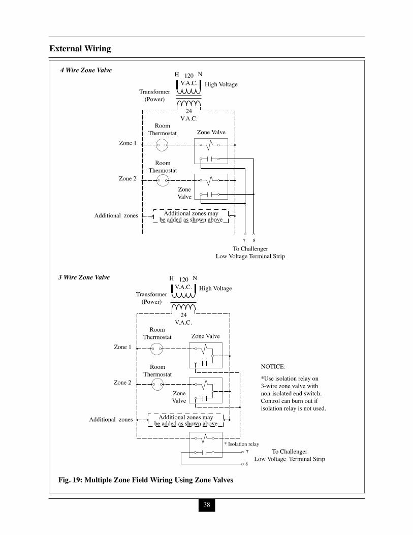
38
External Wiring
H NHigh Voltage
120V.A.C.
24V.A.C.
RoomThermostat
RoomThermostat
Zone 1
Zone 2
Additional zones Additional zones maybe added as shown above
To ChallengerLow Voltage Terminal Strip
Transformer(Power)
ZoneValve
Zone Valve
7 8
To ChallengerLow Voltage Terminal Strip
H N High Voltage
120 V.A.C.
24 V.A.C.
Room Thermostat
Room Thermostat
Zone 1
Zone 2
Additional zones Additional zones may be added as shown above
Transformer (Power)
Zone Valve
Zone Valve
* Isolation relay 7
8
*Use isolation relay on 3-wire zone valve with non-isolated end switch. Control can burn out if isolation relay is not used.
NOTICE:
4 Wire Zone Valve
3 Wire Zone Valve
Fig. 19: Multiple Zone Field Wiring Using Zone Valves
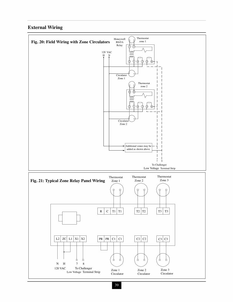
39
External Wiring
T T
To Challenger Low Voltage Terminal Strip
CirculatorZone 1
Thermostatzone 1
HoneywellR845ARelay
120H
VACN
CirculatorZone 2
Thermostatzone 2
Additional zones may beadded as shown above
7 8
62 1 4 3 5
62 1 4 3 5
T T
T T
Fig. 20: Field Wiring with Zone Circulators
Thermostat Zone 1
Zone 1 Circulator
120 VAC N
To ChallengerLow Voltage Terminal Strip Zone 2
Circulator Zone 3 Circulator
Thermostat Zone 2
Thermostat Zone 3
R C T1 T1 T2 T2 T3 T3
C3 C3 C2 C2 C1 C1 PR PR X2 X1 L1 L2 ZC
H 7
8
Fig. 21: Typical Zone Relay Panel Wiring
40
Start-Up PreparationSECTION X - Start-Up Preparation
Check Boiler System Water Chemistry
Do not use petroleum-base cleaning orsealing compounds in the boiler system.Damage to seals and gaskets in the sys-tem components could occur, resulting insubstantial property damage.
System water including additives must bepractically non-toxic, having a toxicityrating or Class of 1, as listed in ClinicalToxicology of Commercial Products.
Water pH Level 6.5 to 8.5Maintain the boiler water pH between 6.5 and8.5. Check using litmus paper or contact a watertreatment company for a chemical analysis.
If the pH does not meet this requirement, do notoperate the CHALLENGER or leave the appli-ance filled, until the condition is corrected.
Water Total Hardness Less Than 7Grains/GallonFor areas with unusually hard water (totalhardness above 7 grains/gallon or 120ppm ormg/l) consult a water treatment company.
Chlorinated WaterDo not use the CHALLENGER to heat aswimming pool or spa directly.
Maintain the chlorine level of the water at lev-els considered safe for drinking.
Flush Boiler and Domestic System toRemove SedimentThe installer must flush the boiler system toremove any sediment to allow proper operationof the CHALLENGER .
Flush the systems until the water runs cleanand is free of sediment.
For zoned systems, each zone should be flushedthrough a purge valve. Purge valves and isola-tion valves should be installed on each zone toallow proper flushing of the system.
Check and Test AntifreezeFor boiler systems containing antifreeze solu-tions, follow the antifreeze manufacturer’sinstructions in verifying the inhibitor level andto ensure the fluid characteristics are withinspecification requirements.
Due to the degradation of inhibitors over time,antifreeze fluids must be periodically replaced.Refer to the manufacturer of the antifreeze foradditional instructions.
System water including additives must bepractically non-toxic, having a toxicityrating or Class of 1, as listed in ClinicalToxicology of Commercial Products.
WARNING
NOTICE
NOTICE

41
Start-Up PreparationUse of Antifreeze in the Boiler System
NEVER use automotive or ethylene gly-col antifreeze or undiluted antifreeze inthe boiler system as freeze protection.This can cause severe personal injury,death or substantial property damage ifignored.
Determine the antifreeze fluid quantity usingthe system water content volume and followingthe antifreeze manufacturer instructions.
The boiler water volume of the CHALLENGERCC 85 is 0.37 gallons [1.4 l], CC 105 is 0.42 gal-lons [1.6 l] and CC 125 is 0.50 gallons [1.9 l].Remember to include this volume in sizing of theexpansion tank.
Check with local codes requirements for theinstallation of backflow preventers or actualdisconnection from the boiler’s cold water fillor make up water supply line.
Massachusetts Code requires the installa-tion of a backflow preventer if antifreezeis used.
Ensure the concentration of antifreeze to waterdoes not exceed a 50/50 ratio.
System water, including additives, mustbe practically non-toxic, having a toxicityrating or Class of 1, as listed in ClinicalToxicology of Commercial Products.
Filling the Boiler System1. Close the boiler drain valve located on the
bottom of the appliance and any manual orautomatic air vent in the system.
2. Open all system isolation valves.3. Fill the boiler system to correct system
pressure. Correct pressure will vary witheach application.
Typical residential system fill pressure is12 psi [0.8 bar]. System pressure willincrease when system temperatureincreases. Operating pressure of the sys-tem should never exceed 25 psi [1.7 bar].
4. Purge air and sediment from each zone ofthe hydronic system through the purgevalves. Open air vents to allow air to bevented from the zones.
5. Once the system is completely filled andpurged of all air and sediment, check thesystem pressure and check/repair any leaks.
Unrepaired system leaks will cause con-tinual makeup water to be added to theappliance. Continual makeup watercould cause mineral buildup within theheat exchanger, reducing the heat trans-fer, causing possible heat buildup andeventual heat exchanger failure.
Check Low Water Cut Off/CH PressureSensor- The CHALLENGER is provided with a
factory installed LWCO that senses boilerCH system pressure of more than 7 psig[0.5 bar].
- Compare CH system pressure gauge read-ing to CHALLENGER’s control pressuredisplay reading, which can only be viewedwhen control is ON and no CH or DHWcall is present. Adjust pressure accordingly.
WARNING
NOTICE
NOTICE
NOTICE
WARNING

42
Start-Up Preparation
Check For Gas Leaks
Prior to start-up and during initial oper-ation, smell near the floor and around theappliance for gas odorant or any unusualodor. Do not proceed with the start-up ifthere is any indication of a gas leak. Anyleaks found must be repaired immediate-ly.
Propane installations only - The propanesupplier mixes an odorant with thepropane to make its presence detectable.In some cases the odorant can fade andthe gas may no longer have an odor.Prior to start-up of the appliance andperiodically after start-up have thepropane supplier check and verify theodorant level.
Check Thermostat Circuit- Disconnect the external thermostat wires
from the control terminal strip, located onthe drop down panel.
- Connect a voltmeter across the wire endsof the external thermostat wiring.
- Energize each thermostat, zone valve andrelay in the external circuit, individuallyand check the voltage reading across thewire ends.
- There should NEVER be voltage mea-sured at the wire ends.
- If voltage is measured at the panel under anycondition, check and correct the externalwiring.
In systems using 3-wire zone valves,backfeed of voltage to the appliance is acommon problem. Use an isolation relayto prevent voltage from the external cir-cuit entering the CHALLENGER con-trol panel.- Reconnect the external thermostat
wires to the control terminal strip.
Inspection of Condensate Drain Assembly1. Inspect and ensure the Condensate Drain
Assembly is properly installed as describedon page 28 and shown in Fig. 13 on page29.
2. Remove the Condensate Drain Assemblyand fill with fresh water.
The condensate drain assembly must beinstalled on the appliance and filled withwater when the CHALLENGER is inoperation. The condensate drain assem-bly prevents flue gas emissions fromentering the condensate line. Failure toensure trap is filled with water couldresult in severe personal injury or death.
3. Re-Install the condensate drain assembly.
WARNING
WARNING
NOTICE
NOTICE
43
Start-Up Procedures
SECTION XI - Start-Up ProceduresFinal Checks Before Start-Upc Read page 46 through 57 regarding the
operation of the CHALLENGER control.c Verify the CHALLENGER and the boiler
system are full of water and all systemcomponents are correctly set for operation,including the minimum flow rate throughthe boiler, see pages 79-81.
c Verify Start-up Preparation items outlined onpages 40 thru 42 have been completed.
c Verify all electrical connections are correctand securely fastened.
c Inspect vent and combustion air piping forsigns of deterioration from corrosion, physicaldamage or sagging. Verify combustion airand vent piping are intact and correctlyinstalled and supported. Reference the properCHALLENGER vent supplement.
c Verify burner configuration - gas orificesize.- Check for proper labeling on the gasvalve (propane only) and the rating labelfor proper gas configuration.- If there is doubt on the burner configura-tion, remove the gas valve and check forproper gas orifice size. See pages 31 and32 for orifice sizes.
c Ensure the vent Condensate DrainAssembly is filled with water.
CHALLENGER Start-Up1. Turn ON the electrical supply/service to the
appliance. Press the ON-OFF button “ ”located on the front control panel to the OFFposition.
2. Read and follow the Operating Instructionsoutlined on page 45.
If CHALLENGER Does Not Start Correctly1. Verify DHW and CH systems are turned
ON (parameter 1) is set to “0”. Read set-ting the appliance parameters section of the
manual starting on page 52 for more infor-mation.
2. Check for loose electrical connections,blown fuse (external or internal at theappliance control) or open service switch.
3. Is the external limit control (if applicable)open? Ensure the external limit is reset tothe closed position.
4. Is the gas supply valve(s) open at the appli-ance and meter?
5. Is incoming gas supply pressure at theappliance more than 5”w.c. [13 mbar] andless than 13” w.c. [32 mbar] for natural orpropane with all gas appliances ON orOFF.
6. Are the heating thermostats set above roomtemperature?
If none of these conditions correct the problem,contact ACV-Triangle Tube Tech Service.
Check the CHALLENGER and Systemc Check Piping.
Check piping and components forleaks. If found, shut down the appli-ance and repair immediately.Purge any remaining air from the systempiping. Air in the system piping willinterfere with circulation creating heatdistribution problems and system noise.
c Check Vent Piping and Combustion AirPiping.
Check for gas-tight seal at every con-nection and seam of the venting andcombustion air piping.
Venting system must be sealed gas-tightto prevent flue gas spillage and potentialcarbon monoxide emissions, which willresult in severe personal injury or death.
WARNING
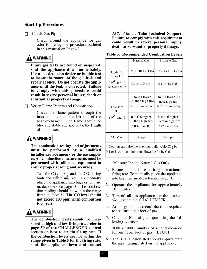
44
Start-Up Proceduresc Check Gas Piping
Check around the appliance for gasodor following the procedure outlinedin this manual on Page 42.
If any gas leaks are found or suspected,shut the appliance down immediately.Use a gas detection device or bubble testto locate the source of the gas leak andrepair at once. Do not operate the appli-ance until the leak is corrected. Failureto comply with this procedure couldresult in severe personal injury, death orsubstantial property damage.
c Verify Flame Pattern and CombustionCheck the flame pattern through theinspection port on the left side of theheat exchanger. The flame should beblue and stable and should be the lengthof the burner.
The combustion testing and adjustmentsmust be performed by a qualifiedinstaller, service agency or the gas suppli-er. All combustion measurements must beperformed with calibrated equipment toensure proper reading and accuracy.
Test for C02 or 02 and for CO duringhigh and low firing rate. To manuallyplace the appliance into high or low firemode, reference page 50. The combus-tion reading should be within the rangelisted in Table 5. The CO level shouldnot exceed 100 ppm when combustionis correct.
The combustion levels should be mea-sured at high and low firing rate, refer topage 50 of the CHALLENGER controlsection on how to set the firing rate. Ifthe combustion levels are not within therange given in Table 5 for the firing rate,shut the appliance down and contact
ACV-Triangle Tube Technical Support.Failure to comply with this requirementcould result in severe personal injury,death or substantial property damage.
Table 5: Recommended Combustion Levels
c Measure Input - Natural Gas Only1. Ensure the appliance is firing at maximum
firing rate. To manually place the applianceinto high fire mode, reference page 50.
2. Operate the appliance for approximately10 minutes.
3. Turn off all gas appliances on the gas ser-vice, except the CHALLENGER.
4. At the gas meter, record the time requiredto use one cubic foot of gas.
5. Calculate Natural gas input using the fol-lowing equation:3600 x 1000 / number of second recordedfor one cubic foot of gas = BTU/H.
6. The BTU/H calculated should approximatethe input rating listed on the appliance.
WARNING
WARNING
WARNING
Natural Gas Propane Gas
High Fire (h or H)
( and +)DOOR OFF*
9% to 10.1% C02 10.5% to 11.1% C02
5% to 3.2% 02 5% to 4.1% 02
Low Fire (L)
( and -)
0 to 0.4 lowerC02 than high fire9.0 % min. C02
0 to 0.4 lower C02than high fire
10.5 % min. C02
0 to 0.6 higher 02 than high fire5.0% max. 02
0 to 0.6 higher 02 than high fire5.0% max. 02
CO Max. 100 ppm 100 ppm
* Door on can raise the maximum allowable C02 by0.4 or lower the minimum allowable 02 by 0.6.
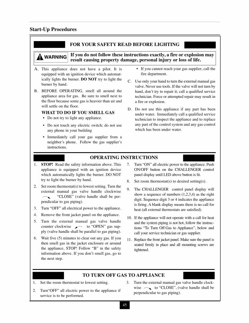
45
Start-Up Procedures
WARNING
FOR YOUR SAFETY READ BEFORE LIGHTING
OPERATING INSTRUCTIONS
TO TURN OFF GAS TO APPLIANCE
1. STOP! Read the safety information above. Thisappliance is equipped with an ignition devicewhich automatically lights the burner. DO NOTtry to light the burner by hand.
2. Set room thermostat(s) to lowest setting. Turn theexternal manual gas valve handle clockwise
“CLOSE” (valve handle shall be per-pendicular to gas piping).
3. Turn “OFF” all electrical power to the appliance.4. Remove the front jacket panel on the appliance.5. Turn the external manual gas valve handle
counter clockwise to “OPEN” gas sup-ply (valve handle shall be parallel to gas piping).
6. Wait five (5) minutes to clear out any gas. If youthen smell gas in the jacket enclosure or aroundthe appliance, STOP! Follow “B” in the safetyinformation above. If you don’t smell gas, go tothe next step.
7. Turn “ON” all electric power to the appliance. PushON/OFF button on the CHALLENGER controlpanel display until LED above button is lit.
8. Set room thermostat(s) to desired setting(s).
9. The CHALLENGER control panel display willshow a sequence of numbers (1,2,3,4) as the rightdigit. Sequence digit 3 or 4 indicates the applianceis firing. A blank display means there is no call forheat (all external thermostats are satisfied).
10. If the appliance will not operate with a call for heatand the system piping is not hot, follow the instruc-tions “To Turn Off Gas to Appliance”, below andcall your service technician or gas supplier.
11. Replace the front jacket panel. Make sure the panel isseated firmly in place and all mounting screws aretightened.
If you do not follow these instructions exactly, a fire or explosion mayresult causing property damage, personal injury or loss of life.
1. Set the room thermostat to lowest setting.
2. Turn“OFF” all electric power to the appliance ifservice is to be performed.
3. Turn the external manual gas valve handle clock-wise to “CLOSE”, (valve handle shall beperpendicular to gas piping).
A. This appliance does not have a pilot. It isequipped with an ignition device which automat-ically lights the burner. DO NOT try to light theburner by hand.
B. BEFORE OPERATING, smell all around theappliance area for gas. Be sure to smell next tothe floor because some gas is heavier than air andwill settle on the floor.WHAT TO DO IF YOU SMELL GAS• Do not try to light any appliance.
• Do not touch any electric switch; do not useany phone in your building
• Immediately call your gas supplier from aneighbor’s phone. Follow the gas supplier’sinstructions.
• If you cannot reach your gas supplier, call thefire department.
C. Use only your hand to turn the external manual gasvalve. Never use tools. If the valve will not turn byhand, don’t try to repair it; call a qualified servicetechnician. Force or attempted repair may result ina fire or explosion.
D. Do not use this appliance if any part has beenunder water. Immediately call a qualified servicetechnician to inspect the appliance and to replaceany part of the control system and any gas controlwhich has been under water.
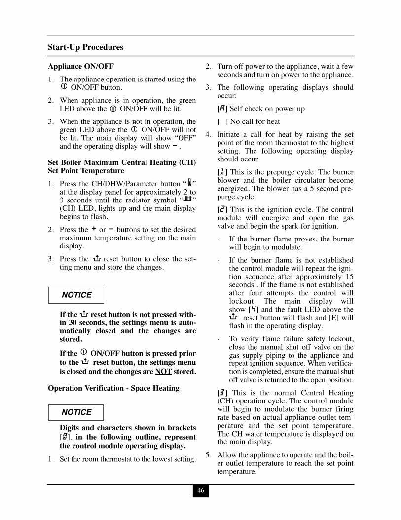
46
Start-Up Procedures
Appliance ON/OFF1. The appliance operation is started using the
ON/OFF button.2. When appliance is in operation, the green
LED above the ON/OFF will be lit.3. When the appliance is not in operation, the
green LED above the ON/OFF will notbe lit. The main display will show “OFF”and the operating display will show .
Set Boiler Maximum Central Heating (CH)Set Point Temperature1. Press the CH/DHW/Parameter button “ ”
at the display panel for approximately 2 to3 seconds until the radiator symbol “ ”(CH) LED, lights up and the main displaybegins to flash.
2. Press the or buttons to set the desiredmaximum temperature setting on the maindisplay.
3. Press the reset button to close the set-ting menu and store the changes.
If the reset button is not pressed with-in 30 seconds, the settings menu is auto-matically closed and the changes arestored.If the ON/OFF button is pressed priorto the reset button, the settings menuis closed and the changes are NOT stored.
Operation Verification - Space Heating
Digits and characters shown in brackets[0], in the following outline, representthe control module operating display.
1. Set the room thermostat to the lowest setting.
2. Turn off power to the appliance, wait a fewseconds and turn on power to the appliance.
3. The following operating displays shouldoccur:[A] Self check on power up[ ] No call for heat
4. Initiate a call for heat by raising the setpoint of the room thermostat to the highestsetting. The following operating displayshould occur[1] This is the prepurge cycle. The burnerblower and the boiler circulator becomeenergized. The blower has a 5 second pre-purge cycle. [2] This is the ignition cycle. The controlmodule will energize and open the gasvalve and begin the spark for ignition.- If the burner flame proves, the burner
will begin to modulate.- If the burner flame is not established
the control module will repeat the igni-tion sequence after approximately 15seconds . If the flame is not establishedafter four attempts the control willlockout. The main display willshow [4] and the fault LED above the
reset button will flash and [E] willflash in the operating display.
- To verify flame failure safety lockout,close the manual shut off valve on thegas supply piping to the appliance andrepeat ignition sequence. When verifica-tion is completed, ensure the manual shutoff valve is returned to the open position.
[3] This is the normal Central Heating(CH) operation cycle. The control modulewill begin to modulate the burner firingrate based on actual appliance outlet tem-perature and the set point temperature.The CH water temperature is displayed onthe main display.
5. Allow the appliance to operate and the boil-er outlet temperature to reach the set pointtemperature.
NOTICE
NOTICE
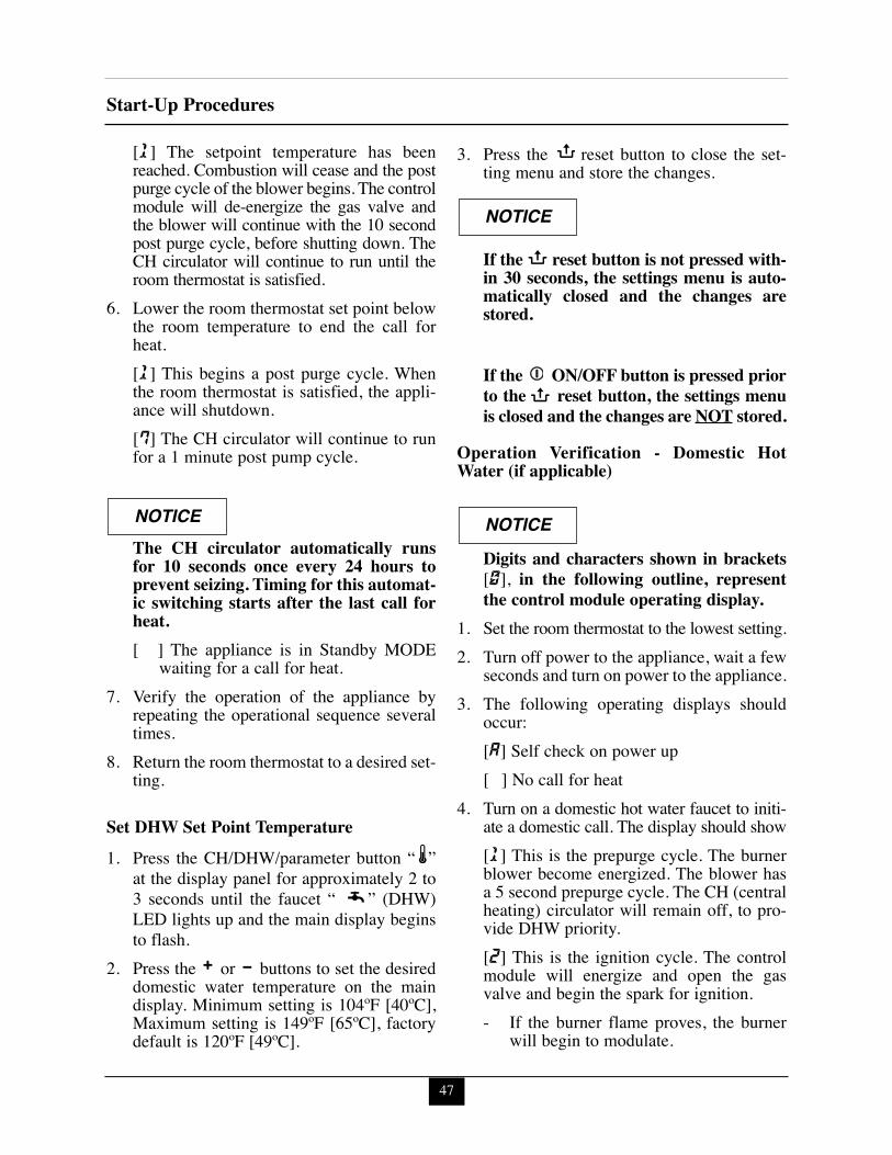
47
Start-Up Procedures
[1] The setpoint temperature has beenreached. Combustion will cease and the postpurge cycle of the blower begins. The controlmodule will de-energize the gas valve andthe blower will continue with the 10 secondpost purge cycle, before shutting down. TheCH circulator will continue to run until theroom thermostat is satisfied.
6. Lower the room thermostat set point belowthe room temperature to end the call forheat.[1] This begins a post purge cycle. Whenthe room thermostat is satisfied, the appli-ance will shutdown. [7] The CH circulator will continue to runfor a 1 minute post pump cycle.
The CH circulator automatically runsfor 10 seconds once every 24 hours toprevent seizing. Timing for this automat-ic switching starts after the last call forheat.[ ] The appliance is in Standby MODE
waiting for a call for heat.7. Verify the operation of the appliance by
repeating the operational sequence severaltimes.
8. Return the room thermostat to a desired set-ting.
Set DHW Set Point Temperature1. Press the CH/DHW/parameter button “ ”
at the display panel for approximately 2 to3 seconds until the faucet “ ” (DHW)LED lights up and the main display beginsto flash.
2. Press the or buttons to set the desireddomestic water temperature on the maindisplay. Minimum setting is 104ºF [40ºC],Maximum setting is 149ºF [65ºC], factorydefault is 120ºF [49ºC].
3. Press the reset button to close the set-ting menu and store the changes.
If the reset button is not pressed with-in 30 seconds, the settings menu is auto-matically closed and the changes arestored.
If the ON/OFF button is pressed priorto the reset button, the settings menuis closed and the changes are NOT stored.
Operation Verification - Domestic HotWater (if applicable)
Digits and characters shown in brackets[0], in the following outline, representthe control module operating display.
1. Set the room thermostat to the lowest setting.2. Turn off power to the appliance, wait a few
seconds and turn on power to the appliance.3. The following operating displays should
occur:[A] Self check on power up[ ] No call for heat
4. Turn on a domestic hot water faucet to initi-ate a domestic call. The display should show[1] This is the prepurge cycle. The burnerblower become energized. The blower hasa 5 second prepurge cycle. The CH (centralheating) circulator will remain off, to pro-vide DHW priority.[2] This is the ignition cycle. The controlmodule will energize and open the gasvalve and begin the spark for ignition.- If the burner flame proves, the burner
will begin to modulate.
NOTICE
NOTICE
NOTICE
48
Start-Up Procedures- If the burner flame is not established
the control module will repeat the igni-tion sequence after approximately 15seconds . If the flame is not establishedafter four attempts the control willlockout and the main display willshow [4]and the fault LED above the
reset button will flash and [E] willflash in the operating display.
- To verify flame failure safety lockout,close the manual shut off valve on thegas supply piping to the appliance andrepeat ignition sequence. When verifi-cation is completed, ensure the manualshut off valve is returned to the openposition.
[4] This is the normal DHW operationcycle. The control module will begin tomodulate the burner firing rate based onactual DHW set point temperature. TheDHW water temperature is displayed inthe main display.
5. Turn off the domestic hot water faucet toend the call for heat.[1] This begins a post purge cycle. Thecontrol module closes the gas valve and theblower continues to operate for approxi-mately 10 seconds.
6. Verify the DHW operation by repeating theoutlined operation sequence several times.
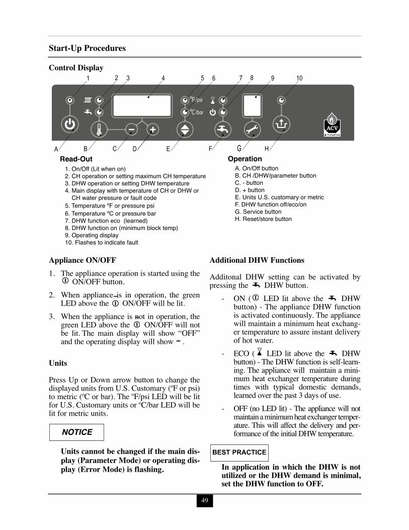
49
Start-Up Procedures
Control Display
Appliance ON/OFF1. The appliance operation is started using the
ON/OFF button.2. When appliance is in operation, the green
LED above the ON/OFF will be lit.3. When the appliance is not in operation, the
green LED above the ON/OFF will notbe lit. The main display will show “OFF”and the operating display will show .
UnitsPress Up or Down arrow button to change thedisplayed units from U.S. Customary (ºF or psi)to metric (ºC or bar). The ºF/psi LED will be litfor U.S. Customary units or ºC/bar LED will belit for metric units.
Units cannot be changed if the main dis-play (Parameter Mode) or operating dis-play (Error Mode) is flashing.
Additional DHW FunctionsAdditonal DHW setting can be activated bypressing the DHW button.
- ON ( LED lit above the DHWbutton) - The appliance DHW functionis activated continuously. The appliancewill maintain a minimum heat exchang-er temperature to assure instant deliveryof hot water.
- ECO ( LED lit above the DHWbutton) - The DHW function is self-learn-ing. The appliance will maintain a mini-mum heat exchanger temperature duringtimes with typical domestic demands,learned over the past 3 days of use.
- OFF (no LED lit) - The appliance will notmaintain a minimum heat exchanger temper-ature. This will affect the delivery and per-formance of the initial DHW temperature.
In application in which the DHW is notutilized or the DHW demand is minimal,set the DHW function to OFF.
NOTICE
BEST PRACTICE
1. On/Off (Lit when on)2. CH operation or setting maximum CH temperature3. DHW operation or setting DHW temperature4. Main display with temperature of CH or DHW or CH water pressure or fault code5. Temperature ºF or pressure psi6. Temperature ºC or pressure bar7. DHW function eco (learned)8. DHW function on (minimum block temp)9. Operating display10. Flashes to indicate fault
A. On/Off button B. CH /DHW/parameter buttonC. - buttonD. + buttonE. Units U.S. customary or metric F. DHW function off/eco/onG. Service buttonH. Reset/store button
Read-Out Operation

50
Start-Up ProceduresTest Mode FunctionTO TEMPORARILY PLACE THE BURN-ER INTO HIGH FIRE TEST MODE: pressand hold both the “ ” and “+” button simul-taneously once until operating display shows“h” for CH high fire or twice until the operat-ing display shows “H” for DHW high fire.
While in the test mode:- high limit will function- appliance CH circulator will function- the test mode will time out in approxi-
mately 10 minutes
TO TEMPORARILY PLACE THE BURN-ER INTO LOW FIRE TEST MODE: pressand hold both the “ ” and “ ” button simul-taneously until operating display shows “L”.
Flame CurrentWhile in high fire or low fire test modes theflame current (µA) can be checked at the con-trol by pressing and holding the “ ” DHWbutton.
TO DEACTIVATE THE HIGH OR LOWFIRE TEST MODE: press and hold both the“+” and “-” button simultaneously.
Control Software VersionTo view the control sofware version cycle theincoming power off then on to the CHAL-LENGER at the wall switch.
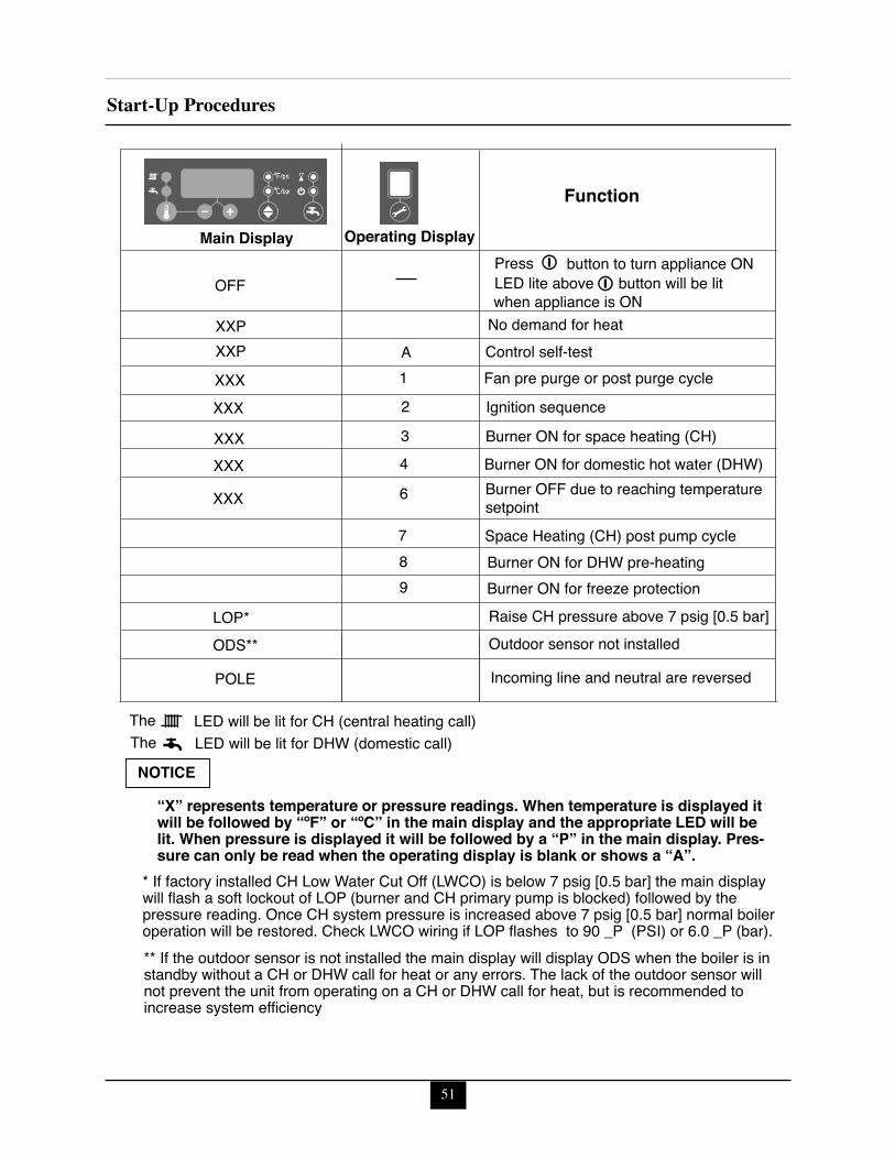
51
Start-Up Procedures
Function
Main Display Operating Display
OFF
XXPXXP
XXX
7
Press
No demand for heatControl self-testFan pre purge or post purge cycle
Space Heating (CH) post pump cycle
XXX
XXX
6
A1
Ignition sequence
XXX
2Burner ON for space heating (CH)
XXX
LOP*
3Burner ON for domestic hot water (DHW)4
Burner ON for DHW pre-heating
Raise CH pressure above 7 psig [0.5 bar]ODS** Outdoor sensor not installed
POLE Incoming line and neutral are reversed
Burner ON for freeze protection
The LED will be lit for CH (central heating call)
89
Burner OFF due to reaching temperaturesetpoint
button to turn appliance ONLED lite above button will be lit
The LED will be lit for DHW (domestic call)NOTICE
when appliance is ON
“X” represents temperature or pressure readings. When temperature is displayed it will be followed by “ºF” or “ºC” in the main display and the appropriate LED will be lit. When pressure is displayed it will be followed by a “P” in the main display. Pres-sure can only be read when the operating display is blank or shows a “A”.
* If factory installed CH Low Water Cut Off (LWCO) is below 7 psig [0.5 bar] the main display will flash a soft lockout of LOP (burner and CH primary pump is blocked) followed by the pressure reading. Once CH system pressure is increased above 7 psig [0.5 bar] normal boiler operation will be restored. Check LWCO wiring if LOP flashes to 90 _P (PSI) or 6.0 _P (bar).** If the outdoor sensor is not installed the main display will display ODS when the boiler is in standby without a CH or DHW call for heat or any errors. The lack of the outdoor sensor will not prevent the unit from operating on a CH or DHW call for heat, but is recommended to increase system efficiency
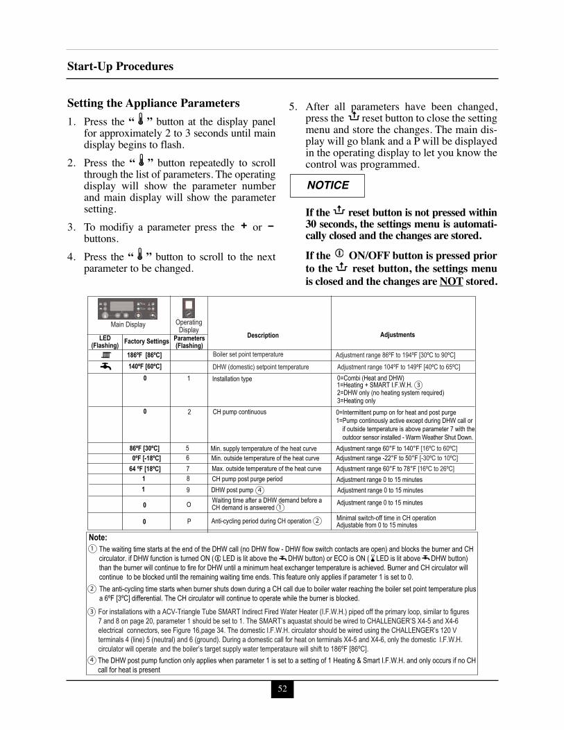
52
Start-Up Procedures
Setting the Appliance Parameters1. Press the “ ” button at the display panel
for approximately 2 to 3 seconds until maindisplay begins to flash.
2. Press the “ ” button repeatedly to scrollthrough the list of parameters. The operatingdisplay will show the parameter numberand main display will show the parametersetting.
3. To modifiy a parameter press the orbuttons.
4. Press the “ ” button to scroll to the nextparameter to be changed.
5. After all parameters have been changed,press the reset button to close the settingmenu and store the changes. The main dis-play will go blank and a P will be displayedin the operating display to let you know thecontrol was programmed.
If the reset button is not pressed within30 seconds, the settings menu is automati-cally closed and the changes are stored.If the ON/OFF button is pressed priorto the reset button, the settings menuis closed and the changes are NOT stored.
NOTICE
AdjustmentsDescriptionParameters(Flashing)Factory SettingsLED
(Flashing)
Installation type 0
186ºF [86ºC]140ºF [60ºC]
0=Combi (Heat and DHW)
2=DHW only (no heating system required) 3=Heating only
CH pump continuous 0 0=Intermittent pump on for heat and post purge1=Pump continously active except during DHW call or if outside temperature is above parameter 7 with the outdoor sensor installed - Warm Weather Shut Down.
1=Heating + SMART I.F.W.H.
Min. supply temperature of the heat curve 86ºF [30ºC] Adjustment range 60°F to 140°F [16ºC to 60ºC] Min. outside temperature of the heat curve 0ºF [-18ºC] Adjustment range -22°F to 50°F [-30ºC to 10ºC] Max. outside temperature of the heat curve 64 ºF [18ºC]
Note:
Adjustment range 60°F to 78°F [16ºC to 26ºC] CH pump post purge period 1 Adjustment range 0 to 15 minutes
Waiting time after a DHW demand before a CH demand is answered 0 Adjustment range 0 to 15 minutes
Anti-cycling period during CH operation
The anti-cycling time starts when burner shuts down during a CH call due to boiler water reaching the boiler set point temperature plus a 6ºF [3ºC] differential. The CH circulator will continue to operate while the burner is blocked.
The waiting time starts at the end of the DHW call (no DHW flow - DHW flow switch contacts are open) and blocks the burner and CH circulator. if DHW function is turned ON ( LED is lit above the DHW button) or ECO is ON ( LED is lit above DHW button)than the burner will continue to fire for DHW until a minimum heat exchanger temperature is achieved. Burner and CH circulator will continue to be blocked until the remaining waiting time ends. This feature only applies if parameter 1 is set to 0.
0 Minimal switch-off time in CH operation Adjustable from 0 to 15 minutes
1
2
5678
O
P
Main Display OperatingDisplay
Boiler set point temperature
DHW (domestic) setpoint temperatureAdjustment range 86ºF to 194ºF [30ºC to 90ºC]Adjustment range 104ºF to 149ºF [40ºC to 65ºC]
For installations with a ACV-Triangle Tube SMART Indirect Fired Water Heater (I.F.W.H.) piped off the primary loop, similar to figures 7 and 8 on page 20, parameter 1 should be set to 1. The SMART’s aquastat should be wired to CHALLENGER’S X4-5 and X4-6 electrical connectors, see Figure 16,page 34. The domestic I.F.W.H. circulator should be wired using the CHALLENGER’s 120 V terminals 4 (line) 5 (neutral) and 6 (ground). During a domestic call for heat on terminals X4-5 and X4-6, only the domestic I.F.W.H. circulator will operate and the boiler’s target supply water temperataure will shift to 186ºF [86ºC].
3
3
2
2
The DHW post pump function only applies when parameter 1 is set to a setting of 1 Heating & Smart I.F.W.H. and only occurs if no CH call for heat is present
4
1
1
DHW post pump1 Adjustment range 0 to 15 minutes 9 4
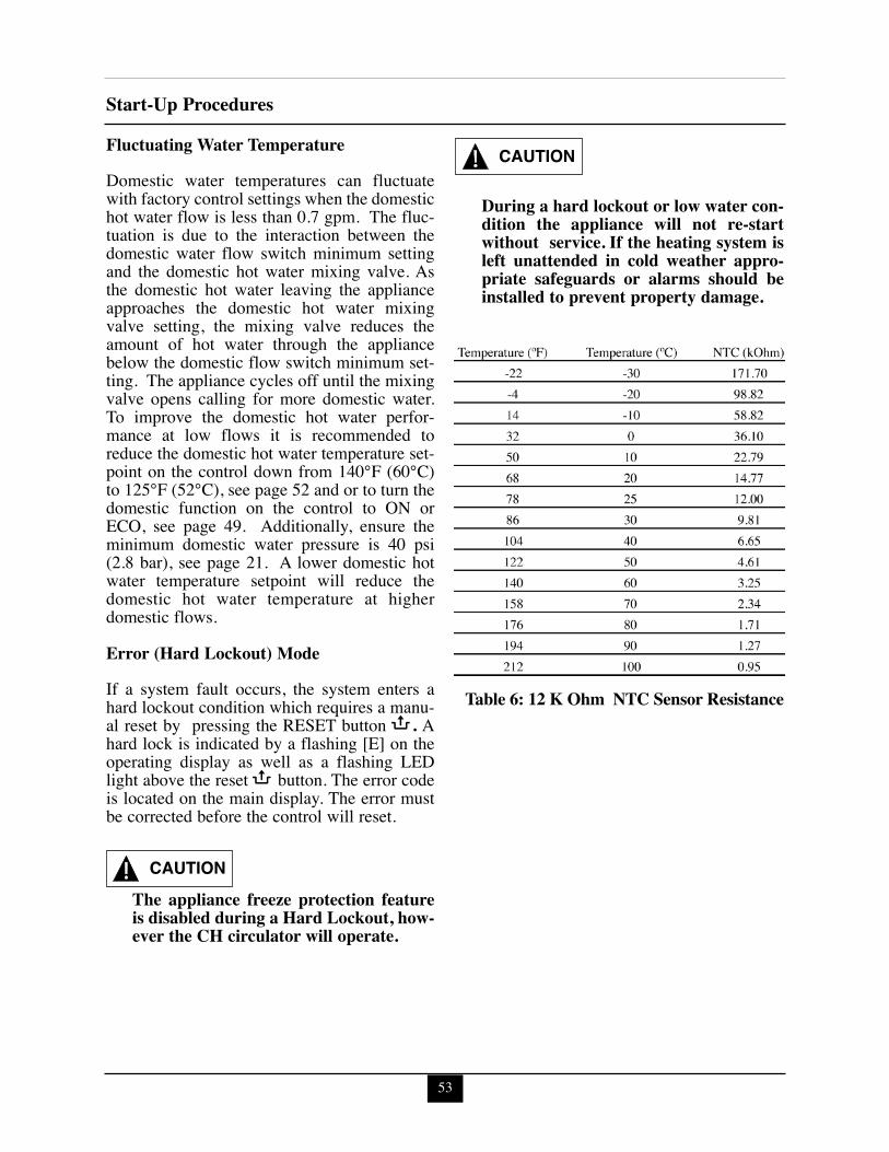
53
Start-Up ProceduresFluctuating Water TemperatureDomestic water temperatures can fluctuatewith factory control settings when the domestichot water flow is less than 0.7 gpm. The fluc-tuation is due to the interaction between thedomestic water flow switch minimum settingand the domestic hot water mixing valve. Asthe domestic hot water leaving the applianceapproaches the domestic hot water mixingvalve setting, the mixing valve reduces theamount of hot water through the appliancebelow the domestic flow switch minimum set-ting. The appliance cycles off until the mixingvalve opens calling for more domestic water.To improve the domestic hot water perfor-mance at low flows it is recommended toreduce the domestic hot water temperature set-point on the control down from 140°F (60°C)to 125°F (52°C), see page 52 and or to turn thedomestic function on the control to ON orECO, see page 49. Additionally, ensure theminimum domestic water pressure is 40 psi(2.8 bar), see page 21. A lower domestic hotwater temperature setpoint will reduce thedomestic hot water temperature at higherdomestic flows.
Error (Hard Lockout) ModeIf a system fault occurs, the system enters ahard lockout condition which requires a manu-al reset by pressing the RESET button . Ahard lock is indicated by a flashing [E] on theoperating display as well as a flashing LEDlight above the reset button. The error codeis located on the main display. The error mustbe corrected before the control will reset.
The appliance freeze protection featureis disabled during a Hard Lockout, how-ever the CH circulator will operate.
During a hard lockout or low water con-dition the appliance will not re-startwithout service. If the heating system isleft unattended in cold weather appro-priate safeguards or alarms should beinstalled to prevent property damage.
CAUTION
CAUTION
Table 6: 12 K Ohm NTC Sensor Resistance
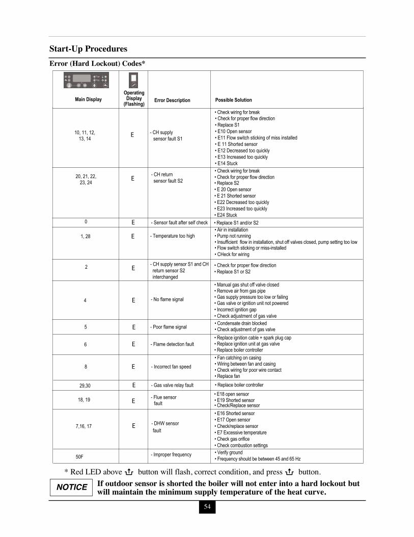
54
Start-Up Procedures
10, 11, 12,
1, 28
4
0
2
29,30
5
6
8
13, 14 sensor fault S1 - CH supply
• Check wiring for break • Check for proper flow direction • Replace S1 • E10 Open sensor• E11 Flow switch sticking of miss installed• E 11 Shorted sensor• E12 Decreased too quickly• E13 Increased too quickly• E14 Stuck
• Replace S2• E 20 Open sensor• E 21 Shorted sensor• E22 Decreased too quickly• E23 Increased too quickly• E24 Stuck
20, 21, 22, 23, 24
- CH return sensor fault S2
• Check wiring for break • Check for proper flow direction
- Sensor fault after self check • Replace S1 and/or S2
- Temperature too high • Air in installation • Pump not running • Insufficient flow in installation, shut off valves closed, pump setting too low • Flow switch sticking or miss-installed• CHeck for wiring
- CH supply sensor S1 and CH return sensor S2 interchanged
• Check for proper flow direction• Replace S1 or S2
- No flame signal
• Manual gas shut off valve closed • Remove air from gas pipe • Gas supply pressure too low or failing • Gas valve or ignition unit not powered• Incorrect ignition gap• Check adjustment of gas valve
- Poor flame signal • Condensate drain blocked • Check adjustment of gas valve
- Flame detection fault • Replace ignition cable + spark plug cap • Replace ignition unit at gas valve• Replace boiler controller
- Incorrect fan speed • Fan catching on casing • Wiring between fan and casing • Check wiring for poor wire contact • Replace fan
- Gas valve relay fault • Replace boiler controller
OperatingDisplay
(Flashing)Main Display Possible SolutionError Description
E
18, 19 fault- Flue sensor • E18 open sensor
• E19 Shorted sensor• Check/Replace sensor
E
7,16, 17 fault- DHW sensor
• E16 Shorted sensor• E17 Open sensor• Check/replace sensor• E7 Excessive temperature• Check gas orifice• Check combustion settings
E
50F - Improper frequency • Verify ground• Frequency should be between 45 and 65 Hz
E
E
E
E
E
E
E
E
E
Error (Hard Lockout) Codes*
NOTICE If outdoor sensor is shorted the boiler will not enter into a hard lockout butwill maintain the minimum supply temperature of the heat curve.
* Red LED above button will flash, correct condition, and press button.
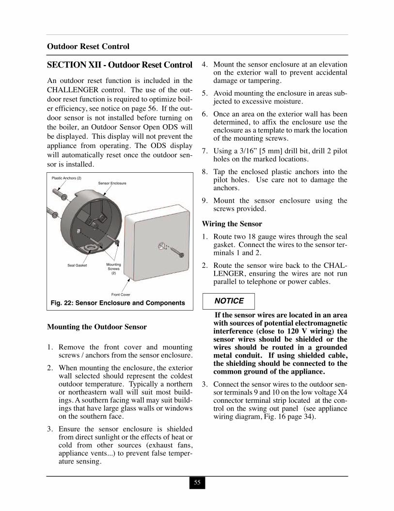
55
Outdoor Reset Control
SECTION XII - Outdoor Reset ControlAn outdoor reset function is included in theCHALLENGER control. The use of the out-door reset function is required to optimize boil-er efficiency, see notice on page 56. If the out-door sensor is not installed before turning onthe boiler, an Outdoor Sensor Open ODS willbe displayed. This display will not prevent theappliance from operating. The ODS displaywill automatically reset once the outdoor sen-sor is installed.
Mounting the Outdoor Sensor
1. Remove the front cover and mountingscrews / anchors from the sensor enclosure.
2. When mounting the enclosure, the exteriorwall selected should represent the coldestoutdoor temperature. Typically a northernor northeastern wall will suit most build-ings. A southern facing wall may suit build-ings that have large glass walls or windowson the southern face.
3. Ensure the sensor enclosure is shieldedfrom direct sunlight or the effects of heat orcold from other sources (exhaust fans,appliance vents...) to prevent false temper-ature sensing.
4. Mount the sensor enclosure at an elevationon the exterior wall to prevent accidentaldamage or tampering.
5. Avoid mounting the enclosure in areas sub-jected to excessive moisture.
6. Once an area on the exterior wall has beendetermined, to affix the enclosure use theenclosure as a template to mark the locationof the mounting screws.
7. Using a 3/16” [5 mm] drill bit, drill 2 pilotholes on the marked locations.
8. Tap the enclosed plastic anchors into thepilot holes. Use care not to damage theanchors.
9. Mount the sensor enclosure using thescrews provided.
Wiring the Sensor1. Route two 18 gauge wires through the seal
gasket. Connect the wires to the sensor ter-minals 1 and 2.
2. Route the sensor wire back to the CHAL-LENGER, ensuring the wires are not runparallel to telephone or power cables.
If the sensor wires are located in an areawith sources of potential electromagneticinterference (close to 120 V wiring) thesensor wires should be shielded or thewires should be routed in a groundedmetal conduit. If using shielded cable,the shielding should be connected to thecommon ground of the appliance.
3. Connect the sensor wires to the outdoor sen-sor terminals 9 and 10 on the low voltage X4connector terminal strip located at the con-trol on the swing out panel (see appliancewiring diagram, Fig. 16 page 34).
NOTICE
Sensor EnclosurePlastic Anchors (2)
Seal Gasket
Front Cover
MountingScrews
(2)
Fig. 22: Sensor Enclosure and Components
56
Outdoor Reset Control
In accordance with Section 325 (f) (3) of theEnergy Policy and Conservation Act, thisboiler is equipped with a feature that savesenergy by reducing the boiler water tem-perature as the heating load decreases. Thisfeature is equipped with an override whichis provided primarily to permit the use ofan external energy management systemthat serves the same function. THIS OVERRIDE MUST NOT BE USEDUNLESS AT LEAST ONE OF THE FOL-LOWING CONDITIONS IS TRUE.
• An external energy management sys-tem is installed that reduces the boilerwater temperature as the heating loaddecreases.
• This boiler is not used for any spaceheating
• This boiler is part of a modular or mul-tiple boiler system having a total inputof 300,000 BTU/hr or greater.
• This boiler is equipped with a tanklesscoil.
Adjusting Outdoor Reset CurveThe appliance CH set point along withParameters 5, 6 & 7 define the settings of theoutdoor reset curve. See Graph 1 and Table 7,page 57 for an example of modifying the out-door reset curve.
CH Maximum Boiler OperatingTemperature
If an outdoor temperature sensor is not con-nected to the appliance, the appliance setpointfor a heating call will be set to the CHMaximum Boiler Operating TemperatureSetpoint. If an outdoor temperature sensor isconnected, the CH Maximum Boiler
Operating Temperature Setpoint becomes theappliance setpoint on the CH Reset CurveColdest Day.
CH Minimum Boiler OperatingTemperature Setpoint(Parameter 5)
This parameter is not applicable if an outdoorsensor is not connected to the appliance. Whenan outdoor temperature sensor is connected, theCH Minimum Boiler Operating TemperatureSetpoint becomes the appliance setpoint on theCH Reset Curve Warmest Day.
CH Reset Curve Coldest Day(Parameter 6)
This parameter is not applicable if an outdoorsensor is not connected to the appliance. Whenan outdoor temperature sensor is connected, theCH Reset Curve Coldest Day is the coldestdesign temperature of the heating system.
CH Reset Curve Warmest Day(Parameter 7)
This parameter is not applicable if an outdoorsensor is not connected to the appliance. Whenan outdoor temperature sensor is connected, theCH Reset Curve Warmest Day is the warmestdesign temperature of the heating system.
NOTICE
Factory Setting Minimum Setting
MaximumSetting
186ºF[86ºC]
86ºF[30ºC]
194ºF[90ºC]
Factory Setting Minimum Setting
MaximumSetting
64ºF[18ºC]
59ºF[16ºC]
77ºF[26ºC]
Factory Setting Minimum Setting
MaximumSetting
00ºF[- 18ºC]
-22ºF[-30ºC]
50ºF[10ºC]
Factory Setting Minimum Setting
MaximumSetting
86ºF[30ºC]
59ºF[16ºC]
140ºF[60ºC]
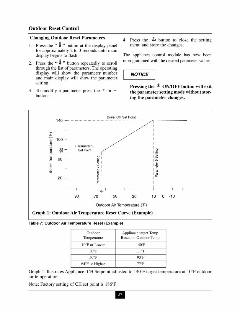
57
Outdoor Reset ControlChanging Outdoor Reset Parameters1. Press the “ ” button at the display panel
for approximately 2 to 3 seconds until maindisplay begins to flash.
2. Press the “ ” button repeatedly to scrollthrough the list of parameters. The operatingdisplay will show the parameter numberand main display will show the parametersetting.
3. To modifiy a parameter press the orbuttons.
4. Press the button to close the settingmenu and store the changes.
The appliance control module has now beenreprogrammed with the desired parameter values.
Pressing the ON/OFF button will exitthe parameter setting mode without stor-ing the parameter changes.
NOTICE
90
20
60
80
100
140
70 64
50 30 10 0 -10
77
Boile
r Tem
pera
ture
( F)
Outdoor Air Temperature ( F)
Boiler CH Set Point
Parameter 5 Set Point
Para
met
er 7
Set
ting
Para
met
er 6
Set
ting
Graph 1: Outdoor Air Temperature Reset Curve (Example)
Table 7: Outdoor Air Temperature Reset (Example)
OutdoorTemperature
Appliance target Temp.Based on Outdoor Temp.
10ºF or Lower 140ºF30ºF 117ºF50ºF 93ºF
64ºF or Higher 77ºF
Graph 1 illustrates Appliance CH Setpoint adjusted to 140ºF target temperature at 10ºF outdoorair temperatureNote: Factory setting of CH set point is 186ºF
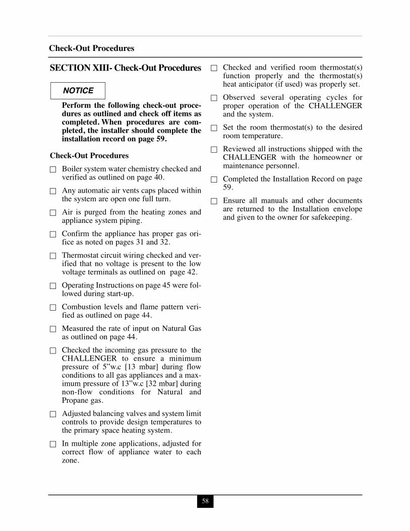
SECTION XIII- Check-Out Procedures
Perform the following check-out proce-dures as outlined and check off items ascompleted. When procedures are com-pleted, the installer should complete theinstallation record on page 59.
Check-Out Proceduresc Boiler system water chemistry checked and
verified as outlined on page 40.c Any automatic air vents caps placed within
the system are open one full turn.c Air is purged from the heating zones and
appliance system piping.c Confirm the appliance has proper gas ori-
fice as noted on pages 31 and 32.c Thermostat circuit wiring checked and ver-
ified that no voltage is present to the lowvoltage terminals as outlined on page 42.
c Operating Instructions on page 45 were fol-lowed during start-up.
c Combustion levels and flame pattern veri-fied as outlined on page 44.
c Measured the rate of input on Natural Gasas outlined on page 44.
c Checked the incoming gas pressure to theCHALLENGER to ensure a minimumpressure of 5”w.c [13 mbar] during flowconditions to all gas appliances and a max-imum pressure of 13”w.c [32 mbar] duringnon-flow conditions for Natural andPropane gas.
c Adjusted balancing valves and system limitcontrols to provide design temperatures tothe primary space heating system.
c In multiple zone applications, adjusted forcorrect flow of appliance water to eachzone.
c Checked and verified room thermostat(s)function properly and the thermostat(s)heat anticipator (if used) was properly set.
c Observed several operating cycles forproper operation of the CHALLENGERand the system.
c Set the room thermostat(s) to the desiredroom temperature.
c Reviewed all instructions shipped with theCHALLENGER with the homeowner ormaintenance personnel.
c Completed the Installation Record on page59.
c Ensure all manuals and other documentsare returned to the Installation envelopeand given to the owner for safekeeping.
NOTICE
Check-Out Procedures
58
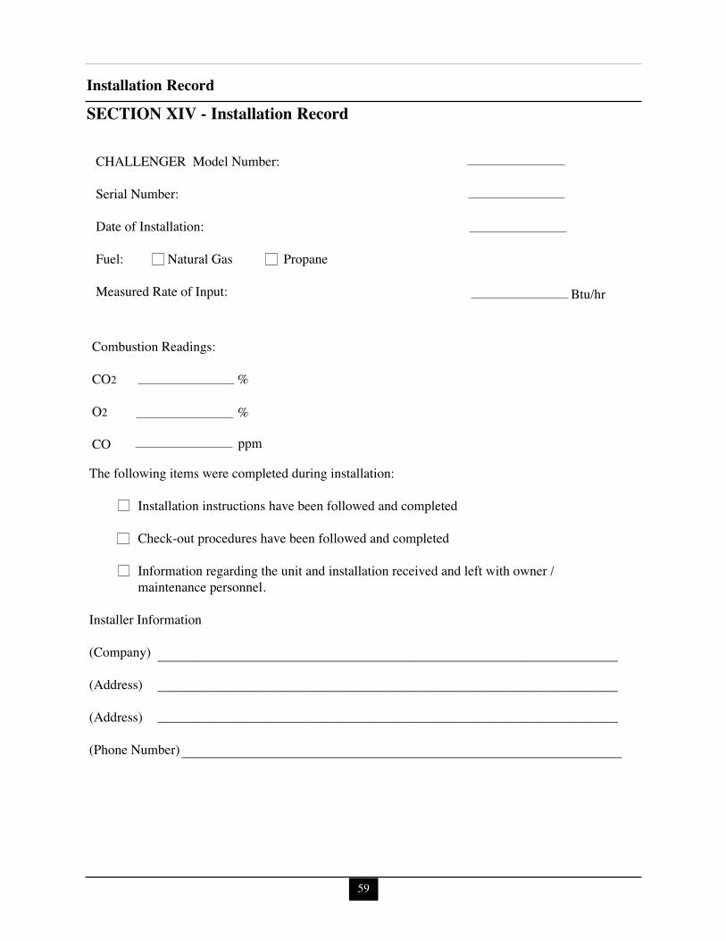
SECTION XIV - Installation Record
CHALLENGER Model Number:
Serial Number:
Date of Installation:
Fuel: Natural Gas Propane
Measured Rate of Input:
Combustion Readings:
CO2
O2
CO
The following items were completed during installation:
Installation instructions have been followed and completed
Check-out procedures have been followed and completed
Information regarding the unit and installation received and left with owner / maintenance personnel.
Installer Information
(Company)
(Address)
(Address)
(Phone Number)
Btu/hr
____________________________________________________________________
____________________________________________________________________
____________________________________________________________________
_________________________________________________________________
%
%
ppm
Installation Record
59
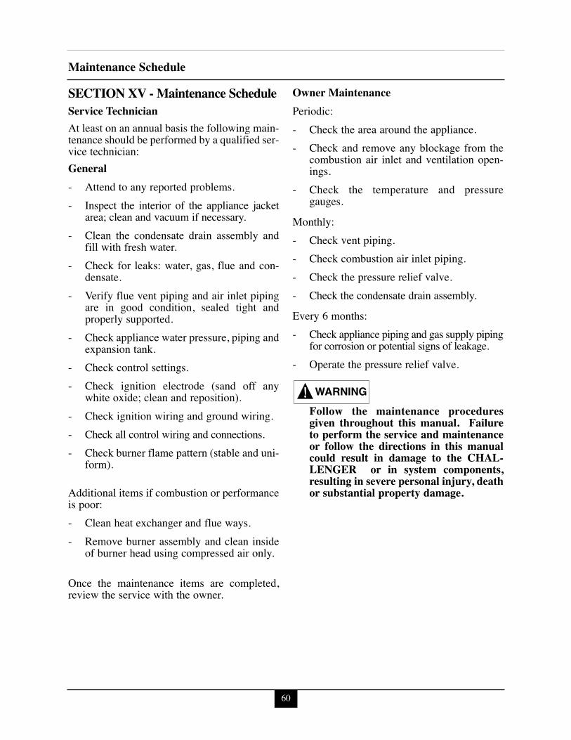
SECTION XV - Maintenance ScheduleService TechnicianAt least on an annual basis the following main-tenance should be performed by a qualified ser-vice technician:General- Attend to any reported problems.- Inspect the interior of the appliance jacket
area; clean and vacuum if necessary.- Clean the condensate drain assembly and
fill with fresh water.- Check for leaks: water, gas, flue and con-
densate.- Verify flue vent piping and air inlet piping
are in good condition, sealed tight andproperly supported.
- Check appliance water pressure, piping andexpansion tank.
- Check control settings.- Check ignition electrode (sand off any
white oxide; clean and reposition).- Check ignition wiring and ground wiring.- Check all control wiring and connections.- Check burner flame pattern (stable and uni-
form).
Additional items if combustion or performanceis poor:- Clean heat exchanger and flue ways.- Remove burner assembly and clean inside
of burner head using compressed air only.
Once the maintenance items are completed,review the service with the owner.
Owner MaintenancePeriodic:- Check the area around the appliance. - Check and remove any blockage from the
combustion air inlet and ventilation open-ings.
- Check the temperature and pressuregauges.
Monthly:- Check vent piping.- Check combustion air inlet piping.- Check the pressure relief valve.- Check the condensate drain assembly.
Every 6 months:- Check appliance piping and gas supply piping
for corrosion or potential signs of leakage.- Operate the pressure relief valve.
Follow the maintenance proceduresgiven throughout this manual. Failureto perform the service and maintenanceor follow the directions in this manualcould result in damage to the CHAL-LENGER or in system components,resulting in severe personal injury, deathor substantial property damage.
WARNING
Maintenance Schedule
60

SECTION XVI - MaintenanceProceduresAnnual Maintenance Procedures
The CHALLENGER should be inspect-ed and serviced annually, preferably atthe start of the heating season, by a qual-ified service technician. In addition, themaintenance and care of the applianceas outlined on page 60 and furtherexplained on pages 61 through 68 shouldbe performed to assure maximum effi-ciency and reliability of the appliance.Failure to service and maintain theCHALLENGER and the system compo-nents could result in equipment failure,causing possible severe personal injury,death or substantial property damage.
The following information providesdetailed instruction for completing themaintenance items outlined in the main-tenance schedule on page 60. In additionto this maintenance, the CHAL-LENGER should be serviced at thebeginning of the heating season by aqualified service technician.
Reported ProblemsAny problems reported by the owner should bechecked, verified and corrected before pro-ceeding with any maintenance procedures.
Check Surrounding Area Verify that the area surrounding the CHAL-LENGER is free of combustible / flammablematerials or flammable vapors or liquids.Remove immediately if found.
Verify that combustion air inlet area is free ofany contaminates. Refer to the materials listedon page 7 of this manual. If any of these prod-ucts are in the area from which the appliancetakes its combustion air, they must be removedimmediately or the combustion air intake mustbe relocated to another area.
Inspect Burner AreaRemove the appliance front jacket panel.
Vacuum any dirt or debris from the blowercomponent.
Re-install front jacket panel when completed.
Do not use solvents to clean any of thecomponents. The components could bedamaged, resulting in unreliable orunsafe operation.
Check System PipingInspect all piping (water and gas) for leaks andverify that the piping is leak free and properlysupported.
Inspect the fittings and components on theappliance and verify they are leak free.
Eliminate all boiler leaks. Continual freshmake-up water will reduce the heatexchanger life causing appliance failure.Leaking water may also cause severeproperty damage to the surrounding area.Inspect the gas supply piping using theprocedure outlined on Page 42.
NOTICE
WARNING
WARNING
WARNING
Maintenance Procedures
61
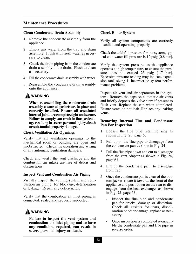
62
Maintenance Procedures
Clean Condensate Drain Assembly1. Remove the condensate assembly from the
appliance.2. Empty any water from the trap and drain
assembly. Flush with fresh water as neces-sary to clean.
3. Check the drain piping from the condensatedrain assembly to the drain. Flush to cleanas necessary.
4. Fill the condensate drain assembly with water. 5. Reassemble the condensate drain assembly
onto the appliance.
When re-assembling the condensate drainassembly ensure all gaskets are in place andcorrectly installed. Ensure all associatedinternal joints are complete, tight and secure.Failure to comply can result in flue gas leak-age resulting in severe personal injury, deathor substantial property damage.
Check Ventilation Air OpeningsVerify that all ventilation openings to themechanical room or building are open andunobstructed. Check the operation and wiringof any automatic ventilation dampers.
Check and verify the vent discharge and thecombustion air intake are free of debris andobstructions.
Inspect Vent and Combustion Air PipingVisually inspect the venting system and com-bustion air piping for blockage, deteriorationor leakage. Repair any deficiencies.
Verify that the combustion air inlet piping isconnected, sealed and properly supported.
Failure to inspect the vent system andcombustion air inlet piping and to haveany conditions repaired, can result insevere personal injury or death.
Check Boiler SystemVerify all system components are correctlyinstalled and operating properly.
Check the cold fill pressure for the system, typ-ical cold water fill pressure is 12 psig [0.8 bar].
Verify the system pressure, as the applianceoperates at high temperature, to ensure the pres-sure does not exceed 25 psig [1.7 bar].Excessive pressure reading may indicate expan-sion tank sizing is incorrect or system perfor-mance problems.
Inspect air vent and air separators in the sys-tem. Remove the caps on automatic air ventsand briefly depress the valve stem if present toflush vent. Replace the cap when completed.Ensure vents do not leak. Replace any leakingvents.
Removing Internal Flue and CondensatePan For Inspection1. Loosen the flue pipe retaining ring as
shown in Fig. 23, page 63.2. Pull up on the flue pipe to disengage from
the condensate pan as show in Fig. 24.3. Pull the flue pipe down and out to disengage
from the vent adapter as shown in Fig. 24,page 63.
4. Lift up the condensate pan to disengagefrom trap.
5. Once the condensate pan is clear of the bot-tom jacket, rotate it towards the front of theappliance and push down on the rear to dis-engage from the heat exchanger as shownin Fig. 25, page 63.- Inspect the flue pipe and condensate
pan for cracks, damage or distortion.Check all gaskets for tears, discol-oration or other damage, replace as nec-essary.
- Once inspection is completed re-assem-ble the condensate pan and flue pipe inreverse order.
WARNING
WARNING
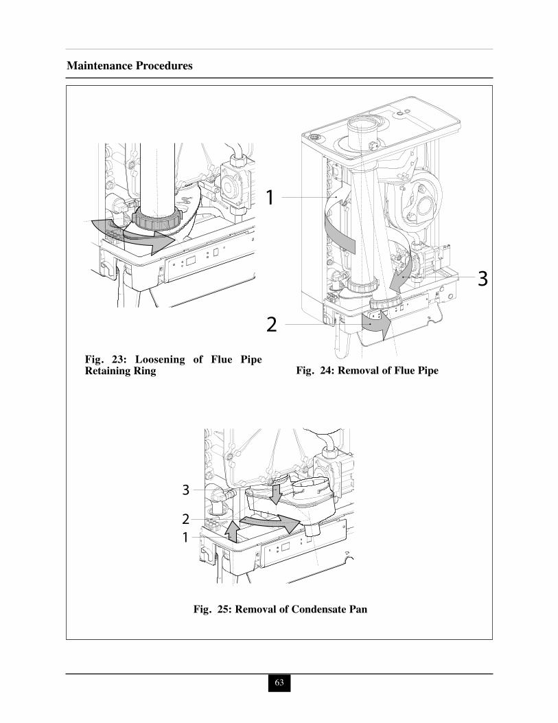
63
Maintenance Procedures
12
3
1
2
3
Fig. 23: Loosening of Flue PipeRetaining Ring
Fig. 25: Removal of Condensate Pan
Fig. 24: Removal of Flue Pipe
64
Maintenance Procedures
When re-assembling the condensate panand flue pipe ensure all gaskets are in placeand correctly installed. Ensure all associat-ed joints are complete, tight and secure.Failure to comply can result in flue gasleakage resulting in severe personal injury,death or substantial property damage.
Check Expansion TankRefer to Section IV - Boiler Piping for rec-ommended location of the expansion tankand air eliminators.Closed -Type Tank:
- Ensure tank is partially filled withwater leaving an air gap as a cushion.Refer to the manufacturer’s instructionfor proper fill level.
- Ensure the tank is fitted with a device thatreduces gravity circulation of air-saturatedtank water back into the system. This deviceprevents air from bubbling up through thewater as it returns from the system.
- Ensure no automatic air vents are usedin the system. This will allow air toescape from the system instead ofreturning to the tank.
Diaphragm Tank:- Ensure the system contains a minimum of
one automatic air vent. Recommendedlocation of the air vent should be atop anair eliminator.
- Remove the tank from the system andcheck the charge pressure. For residentialapplications the charge pressure is typical-ly 12 psig [0.8 bar]. If tank does not holda charge pressure, then the membrane isdamaged and the tank should be replaced.
Check Relief Valve(s)Inspect the relief valve(s) and lift the lever toverify flow at least annually or as recommend-ed on the warning tag of the valve.
Before manually operating the reliefvalve(s), ensure the discharge piping isdirected to a suitable place of disposal toavoid a potential scald hazard. The dis-charge piping must be full size withoutrestriction and installed to permit com-plete drainage of both the valve and line.
If after closing the valve, the valve fails to seatproperly or continually weeps, replace therelief valve. Ensure the cause of the reliefvalve to weep is the valve itself, not due to sys-tem over-pressurization caused by an expan-sion tank that is waterlogged or undersized.
Inspection of Ignition ElectrodeRemove the ignition electrode using a 3 mm orT-15 hex key inserted through the two top panelholes located above the igniter. If necessary sep-arate the top panel from the right side by insert-ing a straight screw driver in two slots on rightside of top panel and bending metal tab in slotsaway from the side. Lift top panel .
Remove any white oxides accumulated on theelectrode using fine grit sandpaper or steel wool.If the electrode does not clean to a satisfactorycondition. Replace the ignitor .
When replacing the ignition electrode, ensurethe gasket is in good condition and correctlypositioned replace gasket if necessary.
Check igniter to Fig. 26, page 65.Check Ignition Wiring and Ground WiringInspect the ignition wiring from the burner con-trol module to the ground at heat exchanger.
Ensure wiring is in good condition and secure-ly connected.
Check ground continuity of the wiring to theappliance heat exchanger or piping using acontinuity meter.
Replace and correct ground wire if ground con-tinuity is not completed and satisfactory.
WARNINGWARNING
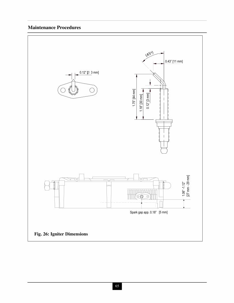
65
Maintenance Procedures
0.12” [ 3 mm]
0.12”
[3 m
m]
0.43” [11 mm]
Spark gap app. 0.18”
1.06”
-1.12
” [2
7 mm
- 29 m
m]
[5 mm]
1.75”
[44 m
m]
1.18”
[30 m
m]
(45º)
Fig. 26: Igniter Dimensions
Check Control WiringInspect all control wiring. Ensure wiring is ingood condition and properly connected.
Check Control Settings1. Check the control CH/DHW/parameter set-
tings by pressing the thermometer button “ ”
on control display. When the LED is lit for “” this is the CH setting. When the LED is lit for“ ” this is the DHW setting. Adjust settingswith “ ” or “ ” buttons as necessary.
2. Press the reset button to close the set-ting menu and store the changes.
3. Check any external limit control settings (ifused). Adjust settings as necessary.
Perform Start-up and Checkout ProceduresStart the appliance and perform the start-upprocedure as listed in this manual.
Verify the cold water fill pressure is correct andthe operating pressure of the boiler is withinnormal operating range.
Complete the checkout procedures as refer-enced in this manual.
Check Burner FlameInspect the burner flame through the observa-tion port on left side off the heat exchanger.
Verify flame pattern is blue and covers the entireburner surface during high fire. Ensure combus-tion at both high and lowfire meet the require-ments listed in Table 5, page 44. If combustion isOK and flame pattern is not fully blue & coversthe entire burner surface during highfire, shut theappliance down and allow it to cool thoroughlybefore disassembly.
Close the external manual gas valve on the gassupply line and disconnect the gas piping andelectrical connector to the gas valve inside theappliance.
Disconnect the wiring harness connectors fromthe blower.
Remove the mounting bolts and washers secur-ing the front of the heat exchanger and set boltsand washers aside.
Carefully remove the front plate of the heatexchanger. Ensure combustion chamber insula-tion is not damaged during removal. SeeWARNING on page 68.
Remove the burner head mounting screws andremove the burner head. Inspect the burner headfor deterioration. Use compressed air or a vac-uum to clean the burner head. Replace burnerhead if necessary. Replace burner head gasket.
Re-assemble the burner head and burner headgasket. Ensure mounting screws are tight.
Remove the blower.
Use a vacuum cleaner or compressed air toclean the interior of the blower and venturiassembly. Inspect the blower blades to ensurethey are clean and not damaged.
Re-assemble the blower and venturi onto frontplate of the heat exchanger . Ensure all gas-kets are in good condition, and positioned cor-rectly. Replace gaskets if necessary.
Re-assemble the front plate of the heatexchanger with bolts and washers onto the heatexchanger. Ensure the gasket and combustionchamber insulation is in place and not dam-aged, replace gasket and insulation if neces-sary. See WARNING on page 68. Ensure allscrews and bolts are tight.
Reconnect the wiring harness connectors to theblower.
Re-assemble the gas supply connections andelectrical connector to gas valve inside theappliance. Open the external manual gas valve.Check gas piping for any leaks as outlined onpage 42 and repair if necessary. Place the appli-ance back into service.
Maintenance Procedures
66
Check Combustion LevelsRefer to page 44 of this manual for measuringcombustion levels and burner adjustments.
Clean Boiler Heat Exchanger1. Shut down the appliance:
- Follow the instructions on Page 45 "ToTurn Off Gas to Appliance"
- Do not drain the appliance unless it willbe subject to freezing conditions.
- Do not drain the appliance if freezeprotection fluid is used in the system.
2. Allow the appliance to cool down to roomtemperature before servicing.
3. Disconnect the gas piping and electricalconnector to the gas valve.
4. Disconnect the wiring harness connectorsfrom the blower.
5. Remove the mounting bolts and washerssecuring the front of the heat exchangerand set aside.
6. Carefully remove the front plate of the heatexchanger. Ensure combustion chamberinsulation is not damaged during removal.See WARNING on page 68.
7. Use a vacuum cleaner, compressed air orwater to remove any accumulation fromthe heat exchanger flue ways. Do not useany solvent.
8. Re-assemble the front plate of the heatexchanger onto the heat exchanger. Ensurethe gasket and combustion chamber insula-tion is in place and not damaged, replacegasket and insulation if necessary. SeeWARNING on page 68.
9. Re-assemble the blower the wiring harness.10. Reconnect the gas piping and electrical
connector to gas valve. Check for leaks,repair if necessary.
11. Close isolation valves at the appliance boil-er piping to isolate the appliance from theheating system.
12. Attach a hose to the boiler drain valve andflush the boiler thoroughly with freshwater by using the purge valves to allowwater to enter through the make-up waterline to the boiler.
13. Once the boiler has been completelyflushed, return the boiler and system pip-ing back to operation.
14. Perform the required startup and checkoutprocedures as outlined on pages 40 to 58.
Clean Domestic Heat Exchanger
Before cleaning the domestic heatexchanger it is recommended to removethe domestic flow restrictor at the inletof the domestic flow switch and to rein-stall the switch to hasten cleaning.Reinstall the domestic flow restrictorwhen cleaning is complete.
1. Shut down the appliance:- Follow the instruction on Page 45 “To
Turn Off Gas to Appliance”2. Shut off all electrical power feed to the
appliance.3. Allow the appliance to cool down to room
temperature before servicing.4. Close the field installed isolation (shut off)
valves on both the domestic cold and hotwater lines to the appliance as shown infigure 11 & 12 on pages 26 & 27.
5. Submerge one end of hose halfway intocleaning fluid in a clean bucket with 4 gallonsof new undiluted, food grade, white vinegar.
6. Attach other end of hose to a potable(bronze or stainless steel) circulating pumpwith a 2.5 gallon per minute [9.5 liters perminute] flow rate with 32 feet [9.7 meters]of head equivalent to Grundfos UP 26-99BF or Taco 009-SF5, use another hose toconnect from the pump to the fieldinstalled domestic hot water outletdrain/flush valve.
NOTICE
Maintenance Procedures
67
The combustion chamber insulation con-tains ceramic fibers, which are classified asa possible human carcinogen. Whenexposed to extremely high temperatures,the ceramic fibers, which contain crystallinesilica, can be converted into cristobalite.
Avoid Breathing and Contact with Skin and EyesWhen removing or repairing the combustion cham-ber insulation follow these precaution measures:1. Use a NIOSH approved respirator which meets
OSHA requirements for cristobalite dust, similarto N95. Contact NIOSH at 1-800-356-4676 oron the web at www.cdc.gov/niosh for latest -recommendations.
2. Wear long sleeved, loose fitting clothing,gloves and eyes protection.
3. Assure adequate ventilation.4. Wash with soap and water after contact.5. Wash potentially contaminated clothes
separately from other laundry and rinsewashing machine thoroughly.
6. Discard used insulation in an air tight plasticbag.
NIOSH Stated First Aid:Eye/Skin: Immediately irrigateBreathing: Clean fresh air
WARNINGHandling Previously Fired Combustion Chamber Insulation
Maintenance Procedures
68
7. Attach separate hose to the field installeddomestic cold water inlet drain/flush valve.
8. Submerge the other end of this hosehalfway in fluid in the same bucket.
9. Open both drain/flush valves on the domes-tic cold and hot water lines.
To avoid risk of electrocution ensure allpower is off to the appliance before ser-vicing. Use G.F.C.I. protected powersupply to pump. Additionally beforepowering up the circulating pumpensure all hose connections and fittingsare leak free and no water is on the floor.
10. Carefully power up the pump allowing thevinegar to circulate through the domesticheat exchanger for 1 hour.
11. Turn pump off and carefully remove allpower to the pump.
12. Close both drain/flush valves on thedomestic cold and hot water lines.
13. Remove hose from bucket and pump con-nected to the drain/flush valve on thedomestic hot water outlet.
14. Relocate the remaining hose still connectedto the domestic cold water inlet drain/flushvalve to the domestic hot water outletdrain/flush valve and the other end of thishose from the bucket to a suitable drain.
15. Rinse the domestic heat exchanger for 5 min-utes by opening both the domestic hot wateroutlet drain/flush valve and the isolation (shut)off valve on the domestic cold water inlet.
16. Close drain/flush valve on the domestic hotwater outlet.
17. Remove hose from the drain/flush valve onthe domestic hot water outlet.
18. Open the field installed isolation (shut off)valve on the domestic hot water outlet.
19. Turn on all electric to the appliance.20. Perform the required startup and checkout
procedures as outlined on pages 40 to 58.
Review With OwnerEnsure the owner understands the impor-tance to perform the maintenance schedulespecified in this manual.Remind the owner of the importance to call alicensed contractor should the appliance orsystem exhibit any unusual behavior.
WARNING
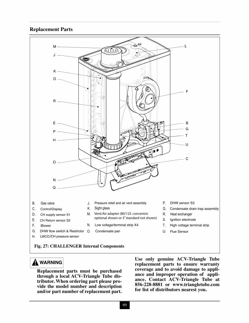
69
Replacement Parts
Pressure relief and air vent assembly
T
S
Low voltage/terminal strip X4
DHW sensor S3
BlowerDHW flow switch & Restrictor
Ignition electrodeHigh voltage terminal strip
Condensate drain trap assembly
Condensate pan
Control/Display
CH Return sensor S2CH supply sensor S1
U
U Flue Sensor
Fig. 27: CHALLENGER Internal Components
Replacement parts must be purchasedthrough a local ACV-Triangle Tube dis-tributor. When ordering part please pro-vide the model number and descriptionand/or part number of replacement part.
Use only genuine ACV-Triangle Tubereplacement parts to ensure warrantycoverage and to avoid damage to appli-ance and improper operation of appli-ance. Contact ACV-Triangle Tube at856-228-8881 or www.triangletube.comfor list of distributors nearest you.
WARNING
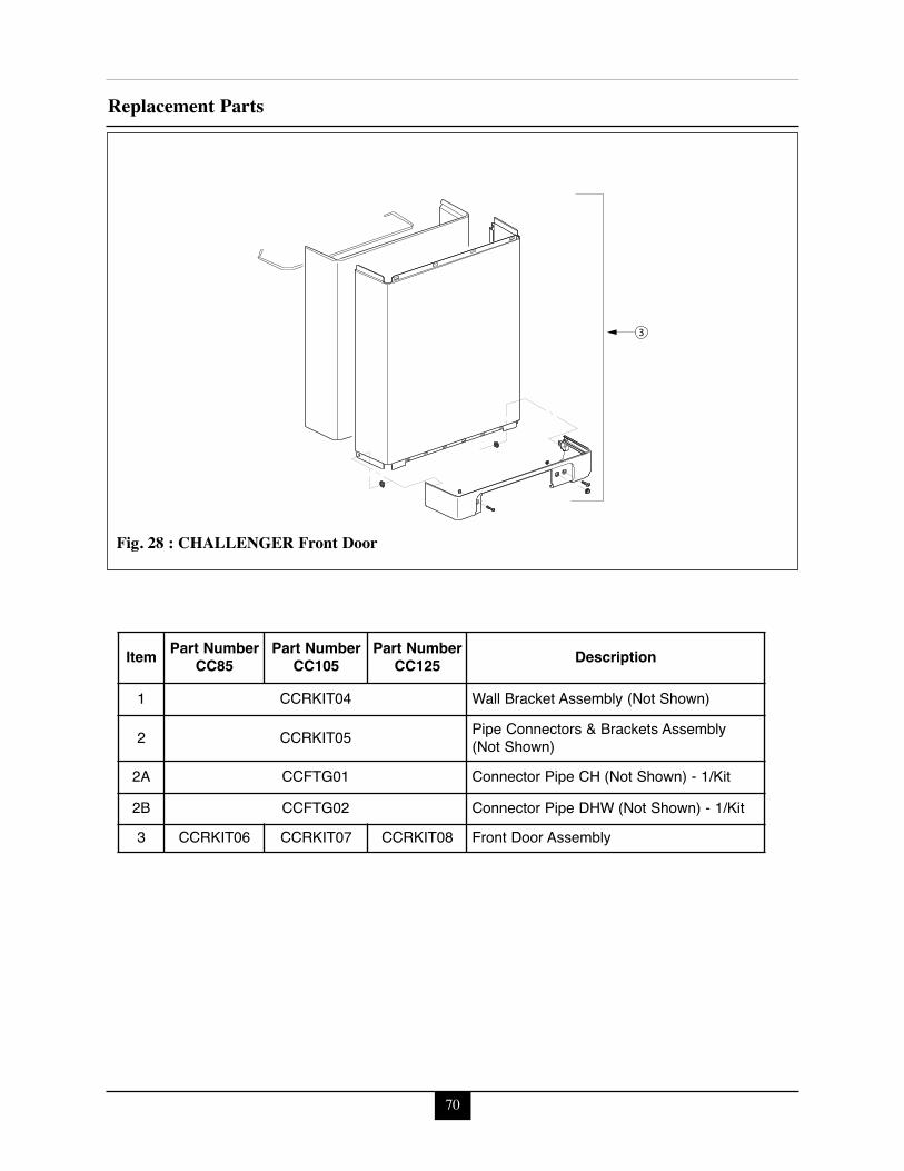
70
Replacement Parts
3
Fig. 28 : CHALLENGER Front Door
Item Part NumberCC85
Part NumberCC105
Part NumberCC125 Description
1 CCRKIT04 Wall Bracket Assembly (Not Shown)
2 CCRKIT05 Pipe Connectors & Brackets Assembly(Not Shown)
2A CCFTG01 Connector Pipe CH (Not Shown) - 1/Kit
2B CCFTG02 Connector Pipe DHW (Not Shown) - 1/Kit3 CCRKIT06 CCRKIT07 CCRKIT08 Front Door Assembly
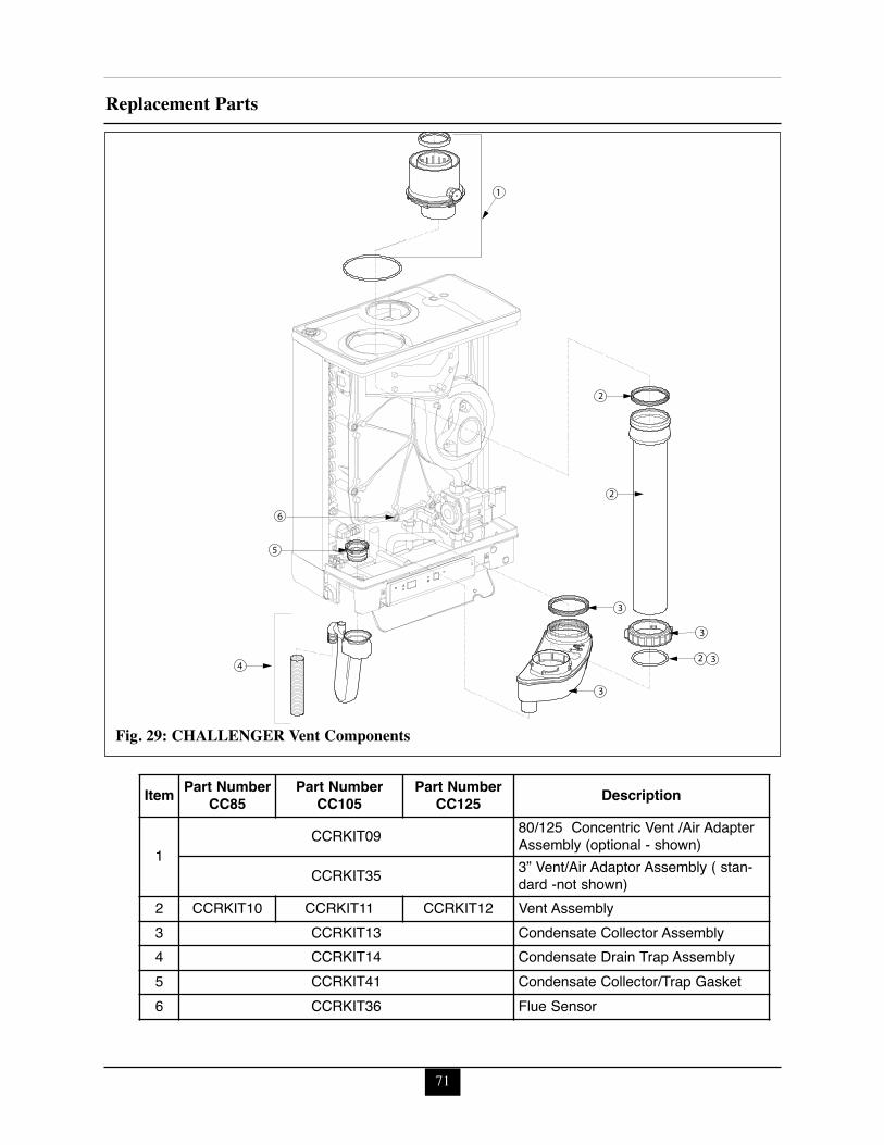
71
Replacement Parts
2
2
3
1
2 3
3
4
3
5
6
Fig. 29: CHALLENGER Vent Components
Item Part NumberCC85
Part NumberCC105
Part NumberCC125 Description
1CCRKIT09 80/125 Concentric Vent /Air Adapter
Assembly (optional - shown)
CCRKIT35 3” Vent/Air Adaptor Assembly ( stan-dard -not shown)
2 CCRKIT10 CCRKIT11 CCRKIT12 Vent Assembly3 CCRKIT13 Condensate Collector Assembly4 CCRKIT14 Condensate Drain Trap Assembly5 CCRKIT41 Condensate Collector/Trap Gasket6 CCRKIT36 Flue Sensor
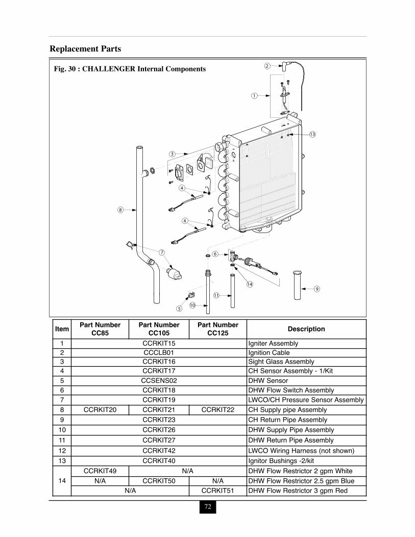
72
Replacement Parts
9
1
3
2
8
11
6
4
105
7
4
13
14
Fig. 30 : CHALLENGER Internal Components
Item Part NumberCC85
Part NumberCC105
Part Number CC125 Description
1 CCRKIT15 Igniter Assembly2 CCCLB01 Ignition Cable3 CCRKIT16 Sight Glass Assembly4 CCRKIT17 CH Sensor Assembly - 1/Kit5 CCSENS02 DHW Sensor6 CCRKIT18 DHW Flow Switch Assembly7 CCRKIT19 LWCO/CH Pressure Sensor Assembly8 CCRKIT20 CCRKIT21 CCRKIT22 CH Supply pipe Assembly9 CCRKIT23 CH Return Pipe Assembly10 CCRKIT26 DHW Supply Pipe Assembly11 CCRKIT27 DHW Return Pipe Assembly12 CCRKIT42 LWCO Wiring Harness (not shown)13 CCRKIT40 Ignitor Bushings -2/kit
14CCRKIT49 N/A DHW Flow Restrictor 2 gpm White
N/A CCRKIT50 N/A DHW Flow Restrictor 2.5 gpm BlueN/A CCRKIT51 DHW Flow Restrictor 3 gpm Red
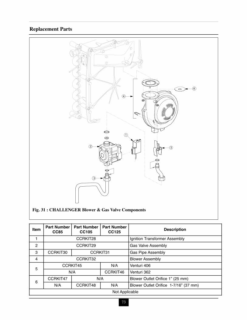
73
Replacement Parts
4
1
2 5
3
6
Fig. 31 : CHALLENGER Blower & Gas Valve Components
Item Part NumberCC85
Part NumberCC105
Part NumberCC125 Description
1 CCRKIT28 Ignition Transformer Assembly2 CCRKIT29 Gas Valve Assembly3 CCRKIT30 CCRKIT31 Gas Pipe Assembly4 CCRKIT32 Blower Assembly
5CCRKIT45 N/A Venturi 406
N/A CCRKIT46 Venturi 362
6CCRKIT47 N/A Blower Outlet Orifice 1” (25 mm)
N/A CCRKIT48 N/A Blower Outlet Orifice 1-7/16” (37 mm) Not Applicable
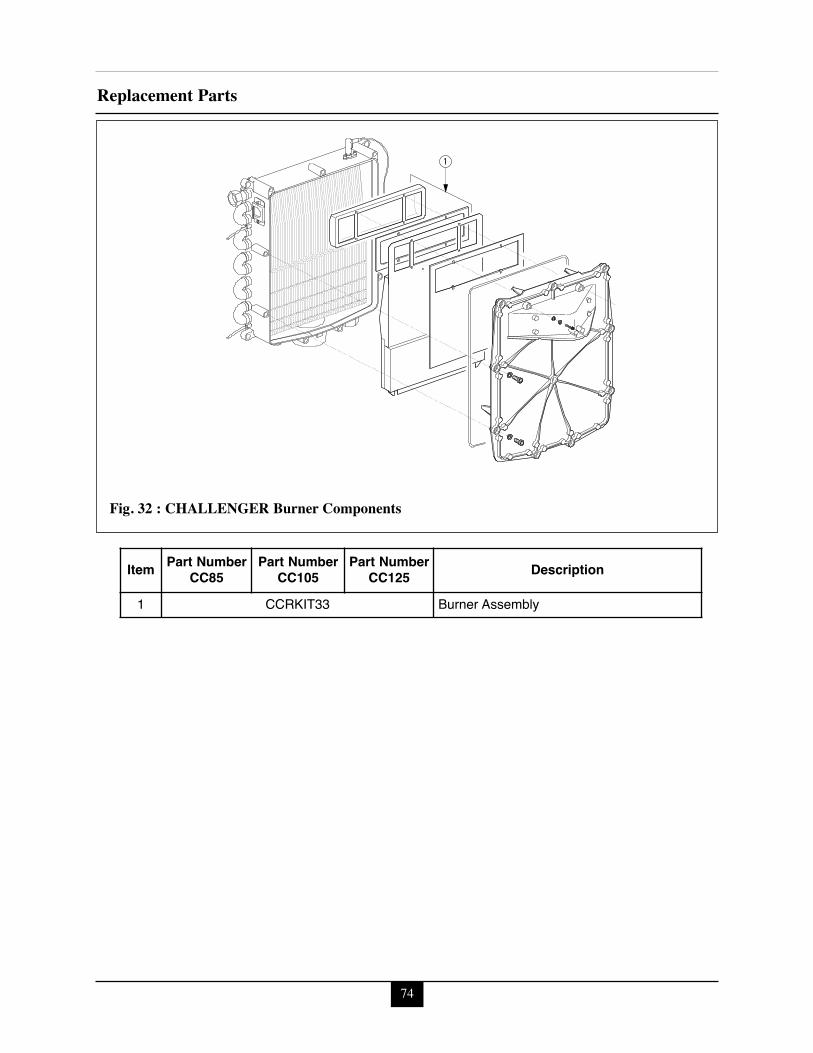
74
Replacement Parts
1
Fig. 32 : CHALLENGER Burner Components
Item Part NumberCC85
Part NumberCC105
Part NumberCC125 Description
1 CCRKIT33 Burner Assembly
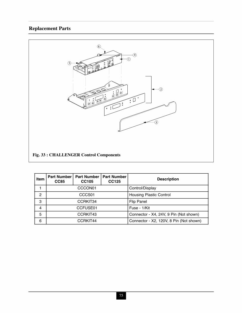
75
Replacement Parts
3
4
2
1
6
5
Fig. 33 : CHALLENGER Control Components
Item Part NumberCC85
Part NumberCC105
Part NumberCC125 Description
1 CCCON01 Control/Display2 CCCS01 Housing Plastic Control 3 CCRKIT34 Flip Panel4 CCFUSE01 Fuse - 1/Kit5 CCRKIT43 Connector - X4, 24V, 9 Pin (Not shown)6 CCRKIT44 Connector - X2, 120V, 8 Pin (Not shown)
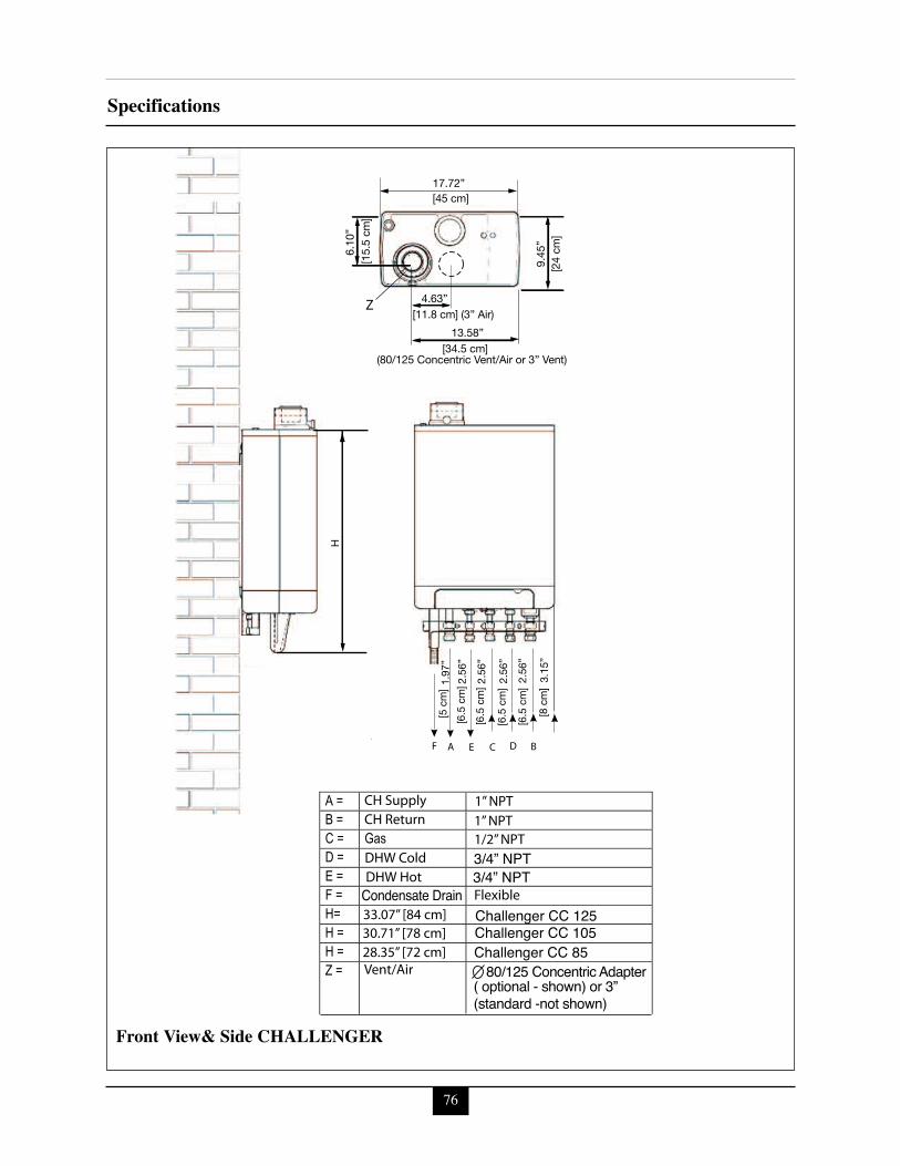
76
Specifications
AF
1.97
”[5
cm
]
[6.5
cm
]
[6.5
cm
]
[6.5
cm
]
[6.5
cm
]
[8 c
m]
2.56
”
2.56
”
2.56
”
2.56
”
3.15
”
H
9.45
”[2
4 cm
]
6.10
”[1
5.5
cm]
E
Z
33.07” [84 cm]30.71” [78 cm]
CH Supply
DHW ColdDHW Hot
Vent/Air
CH Return
28.35” [72 cm]
Flexible
1” NPT1” NPT
1/2” NPT
C D
80/125 Concentric AdapterChallenger CC 85
Condensate Drain
Challenger CC 105Challenger CC 125
3/4” NPT3/4” NPT
B
13.58”[34.5 cm]
(80/125 Concentric Vent/Air or 3” Vent)
4.63”[11.8 cm] (3” Air)
17.72”[45 cm]
( optional - shown) or 3”(standard -not shown)
Front View& Side CHALLENGER
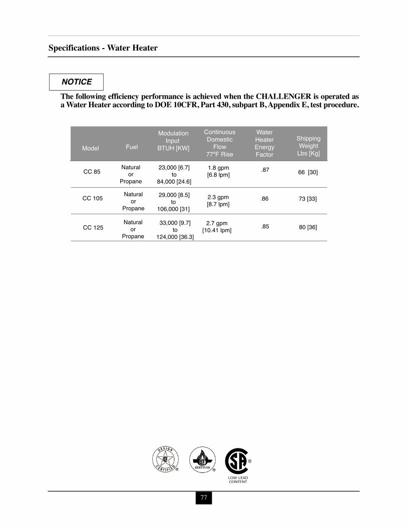
77
Specifications - Water Heater
Fuel
Modulation
Input BTUH [KW]
23,000 [6.7]to
84,000 [24.6]
ShippingWeight
Lbs [Kg]
66 [30]Natural
orPropane
Naturalor
Propane
Naturalor
Propane
Model
CC 85
CC 105
CC 125
110,000
29,000 [8.5]to
106,000 [31]73 [33]
33,000 [9.7]to
124,000 [36.3]80 [36]
WaterHeaterEnergyFactor
ContinuousDomestic
Flow77ºF Rise
2.3 gpm[8.7 lpm]
1.8 gpm[6.8 lpm]
2.7 gpm[10.41 lpm]
.86
.87
.85
The following efficiency performance is achieved when the CHALLENGER is operated asa Water Heater according to DOE 10CFR, Part 430, subpart B, Appendix E, test procedure.
NOTICE
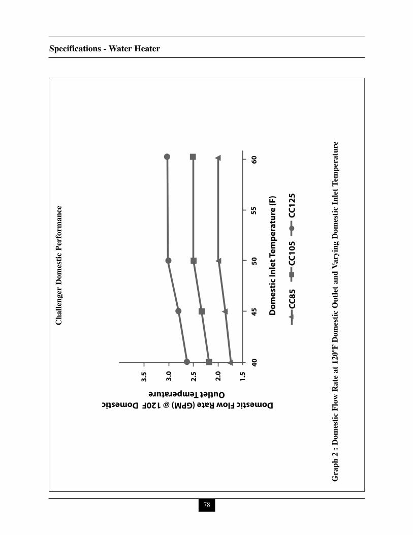
78
Specifications - Water Heater
40
1.5
2.0
2.5
3.0
3.5
4550
5560
CC12
5CC
105
CC85
Dom
esti
c In
let T
empe
ratu
re (F
)
Domestic Flow Rate (GPM) @ 120F Domestic Outlet Temperature
Challenger D
omestic Performance
Graph 2 : Domestic Flow
Rate at 120ºF
Domestic Outlet and Varying D
omestic Inlet Temp
eratu
re
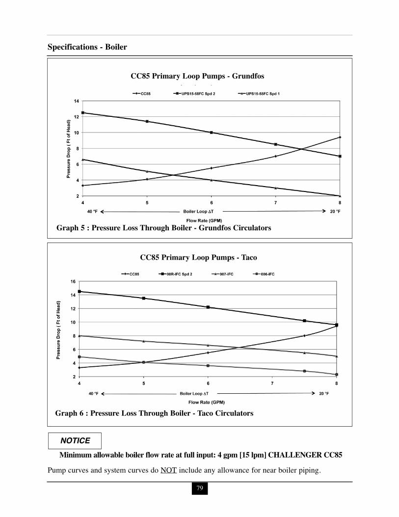
79
Specifications - Boiler
CC85 Primary Loop Pumps - Grundfos
Graph 5 : Pressure Loss Through Boiler - Grundfos Circulators
CC85 Primary Loop Pumps - Taco
Graph 6 : Pressure Loss Through Boiler - Taco Circulators
Minimum allowable boiler flow rate at full input: 4 gpm [15 lpm] CHALLENGER CC85NOTICE
Pump curves and system curves do NOT include any allowance for near boiler piping.
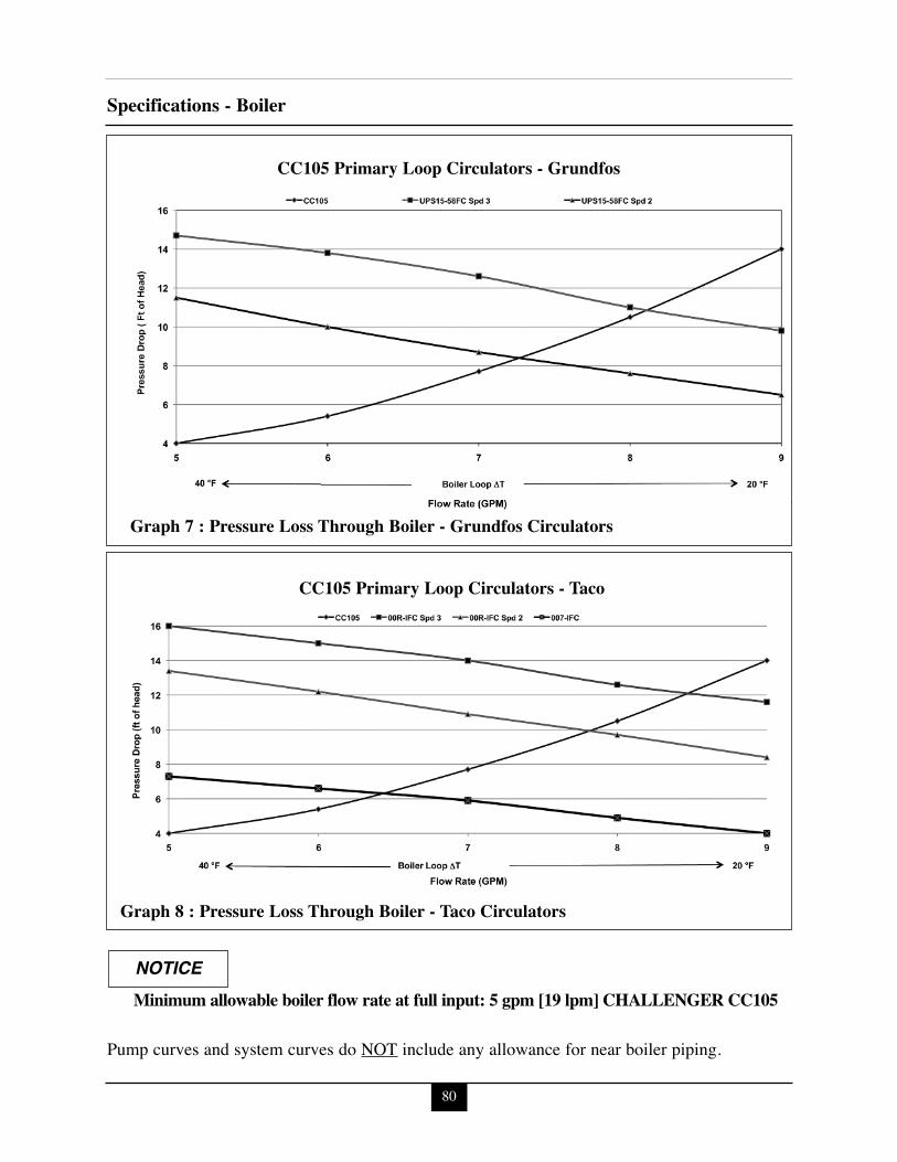
80
Specifications - Boiler
CC105 Primary Loop Circulators - Grundfos
Graph 7 : Pressure Loss Through Boiler - Grundfos Circulators
CC105 Primary Loop Circulators - Taco
Graph 8 : Pressure Loss Through Boiler - Taco Circulators
Minimum allowable boiler flow rate at full input: 5 gpm [19 lpm] CHALLENGER CC105NOTICE
Pump curves and system curves do NOT include any allowance for near boiler piping.
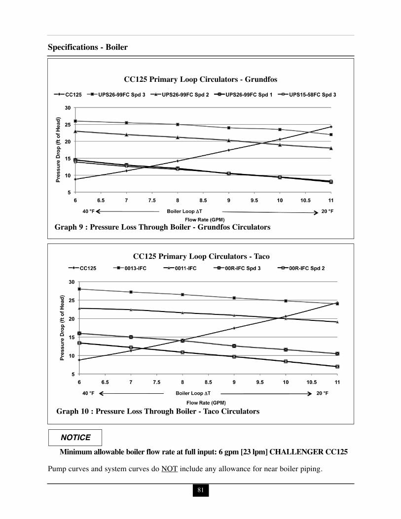
81
Specifications - Boiler
CC125 Primary Loop Circulators - Grundfos
Graph 9 : Pressure Loss Through Boiler - Grundfos Circulators
CC125 Primary Loop Circulators - Taco
Graph 10 : Pressure Loss Through Boiler - Taco Circulators
Minimum allowable boiler flow rate at full input: 6 gpm [23 lpm] CHALLENGER CC125NOTICE
Pump curves and system curves do NOT include any allowance for near boiler piping.
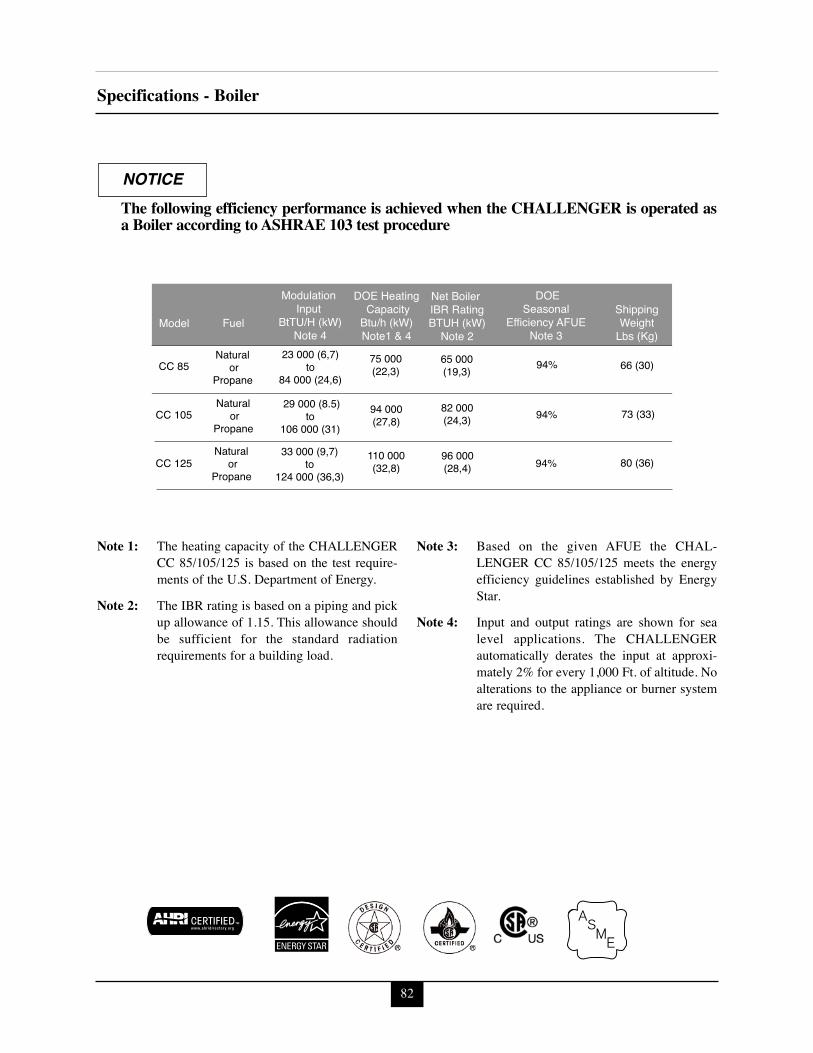
82
Specifications - Boiler
Fuel
DOE Heating CapacityBtu/h (kW)Note1 & 4
Modulation
Input BtTU/H (kW)
Note 4
DOESeasonal
Efficiency AFUENote 3
Net Boiler IBR RatingBTUH (kW)
Note 223 000 (6,7)
to84 000 (24,6)
94%
ShippingWeight
Lbs (Kg)
66 (30)Natural
orPropane
Natural or
Propane
Natural or
Propane
Model
CC 85
CC 105
CC 125
65 000(19,3)110,000
94 000(27,8)
75 000(22,3)
29 000 (8.5)to
106 000 (31)94% 73 (33)82 000
(24,3)
96 000(28,4)
110 000(32,8)
33 000 (9,7)to
124 000 (36,3)94% 80 (36)
Ê
Note 1: The heating capacity of the CHALLENGERCC 85/105/125 is based on the test require-ments of the U.S. Department of Energy.
Note 2: The IBR rating is based on a piping and pickup allowance of 1.15. This allowance shouldbe sufficient for the standard radiationrequirements for a building load.
Note 3: Based on the given AFUE the CHAL-LENGER CC 85/105/125 meets the energyefficiency guidelines established by EnergyStar.
Note 4: Input and output ratings are shown for sealevel applications. The CHALLENGERautomatically derates the input at approxi-mately 2% for every 1,000 Ft. of altitude. Noalterations to the appliance or burner systemare required.
The following efficiency performance is achieved when the CHALLENGER is operated asa Boiler according to ASHRAE 103 test procedure
NOTICE

Notes

Notes

Notes
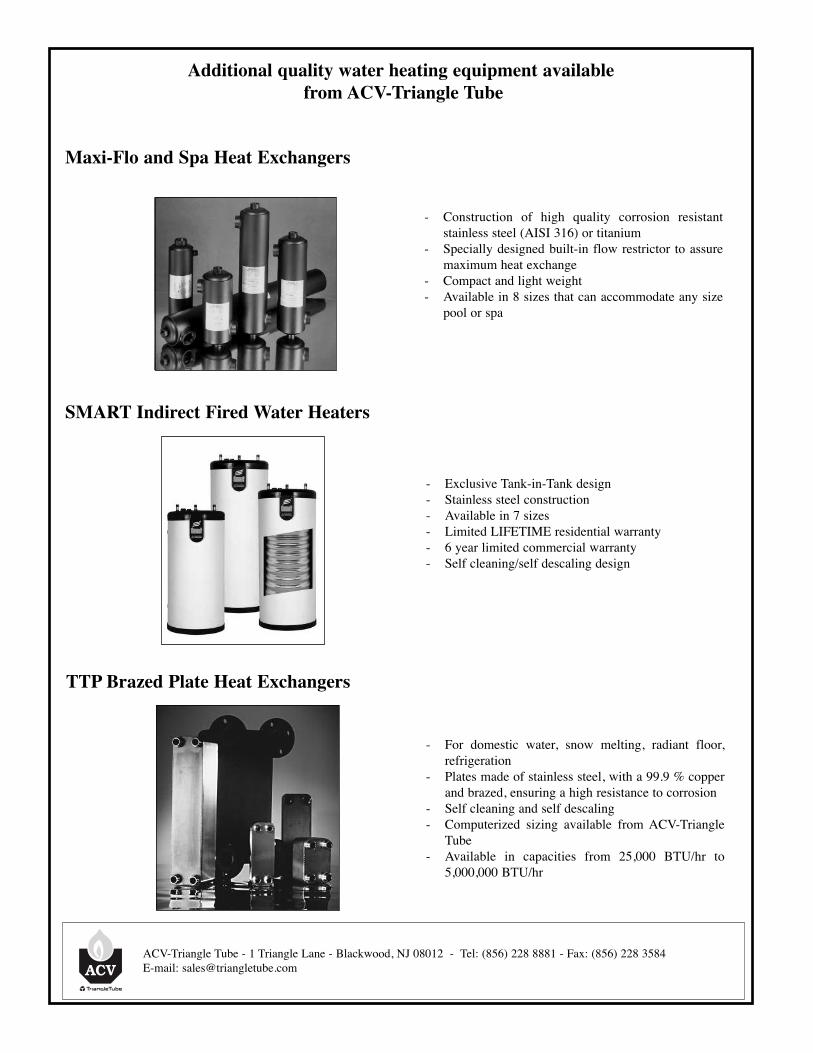
Additional quality water heating equipment availablefrom ACV-Triangle Tube
- Exclusive Tank-in-Tank design- Stainless steel construction- Available in 7 sizes- Limited LIFETIME residential warranty- 6 year limited commercial warranty- Self cleaning/self descaling design
TTP Brazed Plate Heat Exchangers
- For domestic water, snow melting, radiant floor,refrigeration
- Plates made of stainless steel, with a 99.9 % copperand brazed, ensuring a high resistance to corrosion
- Self cleaning and self descaling- Computerized sizing available from ACV-Triangle
Tube- Available in capacities from 25,000 BTU/hr to
5,000,000 BTU/hr
SMART Indirect Fired Water Heaters
Maxi-Flo and Spa Heat Exchangers
- Construction of high quality corrosion resistantstainless steel (AISI 316) or titanium
- Specially designed built-in flow restrictor to assuremaximum heat exchange
- Compact and light weight- Available in 8 sizes that can accommodate any size
pool or spa
ACV-Triangle Tube - 1 Triangle Lane - Blackwood, NJ 08012 - Tel: (856) 228 8881 - Fax: (856) 228 3584E-mail: [email protected]


![Direct Vent Gas Fired Hot Water Boiler INSTALLATION, … · 2015-08-25 · P/N 3771201, Rev.A [01/09] USC SERIES Direct Vent Gas Fired Hot Water Boiler INSTALLATION, OPERATION & MAINTENANCE](https://img.pdfslide.us/doc/110x75/5f9abe8b3e25b46d9e0a5903/direct-vent-gas-fired-hot-water-boiler-installation-2015-08-25-pn-3771201-reva.jpg)