Embed Size (px)
Citation preview
GAS-FIRED, DIRECT VENT, CONDENSING,
HOT WATER BOILER
INSTALLATION, OPERATION AND MAINTENANCE MANUAL
P/N# IM-BW9A-08[240010123, Rev. D [06/2013]
Models (Series B)BW9AAN000050BW9AAN000075BW9AAN000100
CAC/BDP7310 West Morris St.
Indianapolis, IN. 46231
2
DIMENSIONS
2
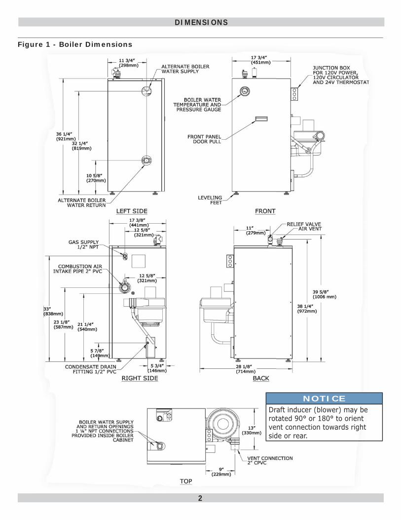
Figure 1 - Boiler Dimensions
NOTICEDraft inducer (blower) may be rotated 90° or 180° to orient vent connection towards right side or rear.
3
INTRODUCTION
Introduction• This appliance is a gas-fi red direct vent hot water boiler
with cast aluminum boiler sections.
• The heating system water absorbs large amounts of heat from the cast aluminum heat exchanger, cooling fl ue gases and causing condensation.
• Sealed combustion, premix gas burner, and low fl ame temperature means reduced CO and NOx emissions, which contribute to cleaner and healthier environment.
• This appliance takes its combustion air directly from outdoors (sealed combustion) and does not compete with building occupants for fresh air.
• Sealed combustion (also known as “direct vent”) is safest and best way to obtain plenty of clean combustion air.
Dimensions ....................................................................................................................2Introduction ...................................................................................................................3Important Safety Information ...........................................................................................4Boiler Ratings & Capacities ..............................................................................................5Boilers For Use At High Altitude - United States Installations ................................................6Before Installing The Boiler ..............................................................................................8Boiler Installation ...........................................................................................................9Near Boiler Piping ......................................................................................................... 11Combustion Air And Vent Pipe ........................................................................................ 22Gas Supply Piping ......................................................................................................... 28Electrical Wiring ........................................................................................................... 30Controls And Accessories ............................................................................................... 34Start Up ...................................................................................................................... 36Operating Instructions ................................................................................................... 37Detailed Sequence Of Operation ..................................................................................... 38Verifi cation Procedure And Adjustment ............................................................................ 42Differential Air Pressure Switch Check - All Models ............................................................ 45Negative Pressure Switch Check ..................................................................................... 46Maintenance And Cleaning ............................................................................................. 47Troubleshooting ............................................................................................................ 49Troubleshooting - High Limit Control And LWCO ............................................................... 50Troubleshooting -Hydrostat High Limit Control And LWCO .................................................. 51Appendix A - Water Quality, Water Treatment And Freeze Protection ........................58Installation And Check-Out Certifi cate ............................................................................. 62
• Induced draft fan draws in outside combustion air, takes cooler fl ue gases from boiler unit and provides positive removal of fl ue gases from the building through readily available PVC, CPVC and PP (Polypropylene) pipes.
• These low pressure gas-fi red hot water boilers are design certifi ed by CSA International for use with natural gas and propane gas.
• Boilers are constructed and hydrostatically tested for maximum working pressure of 50 psig (pounds per square inch gage) in accordance with A.S.M.E. Boiler and Pressure Vessel Code Section IV Standards for heating boilers.
4
Installation shall conform to requirements of authority having jurisdiction or in absence of such requirements:• United States
• National Fuel Gas Code, ANSI Z223.1/NFPA 54.
• National Electrical Code, NFPA 70.
• Canada
• Natural Gas and Propane Installation Code, CAN/CSA B149.1.
• Canadian Electrical Code, Part I, Safety Standard for Electrical Installations, CSA C22.1
Where required by authority having jurisdiction, installation shall conform to Standard for Controls and Safety Devices for Automatically Fired Boilers, ANSI/ASME CSD-1. Additional manual reset low water cutoff and/or manual reset high limit may be required.
Requirements for Commonwealth of Massachusetts: Boiler installation must conform to Commonwealth of Massachusetts code 248 CMR which includes but is not limited to:• Installation by licensed plumber or gas fi tter.
Installers - Follow local regulations with respect to installation of CO (Carbon Monoxide) Detectors. Follow maintenance recommendations “Maintenance And Cleaning” on page 47 .
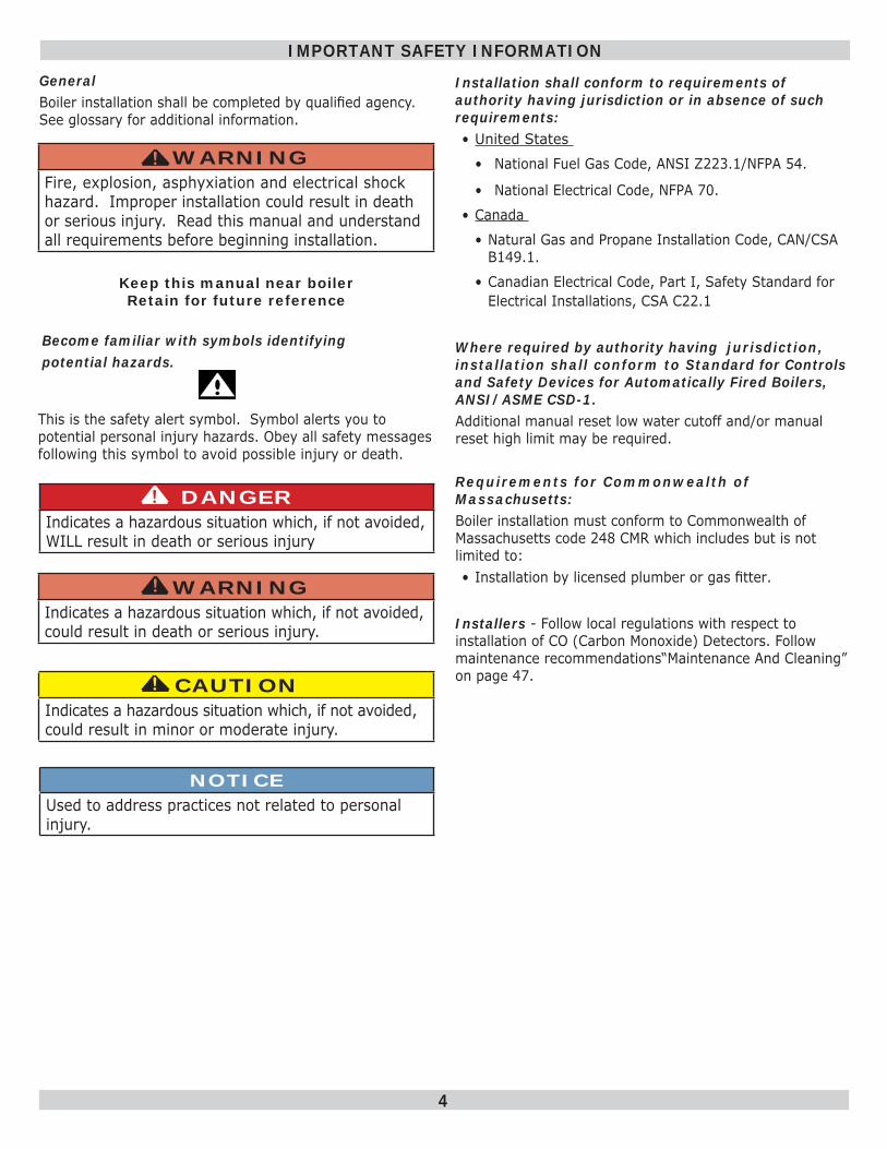
NOTICEUsed to address practices not related to personal injury.
CAUTIONIndicates a hazardous situation which, if not avoided, could result in minor or moderate injury.
!!
WARNINGIndicates a hazardous situation which, if not avoided, could result in death or serious injury.
!
DANGERIndicates a hazardous situation which, if not avoided, WILL result in death or serious injury
!
This is the safety alert symbol. Symbol alerts you to This is the safety alert symbol. Symbol alerts you to potential personal injury hazards. Obey all safety messages potential personal injury hazards. Obey all safety messages following this symbol to avoid possible injury or death.following this symbol to avoid possible injury or death.
Become familiar with symbols identifyingBecome familiar with symbols identifyingpotential hazards.potential hazards.
GeneralBoiler installation shall be completed by qualifi ed agency. See glossary for additional information.
WARNINGFire, explosion, asphyxiation and electrical shock hazard. Improper installation could result in death or serious injury. Read this manual and understand all requirements before beginning installation.
!
IMPORTANT SAFETY INFORMATION
Keep this manual near boilerRetain for future reference
5
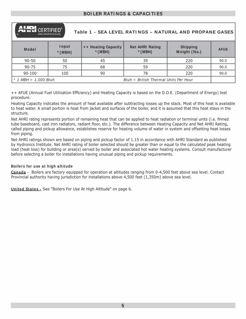
Table 1 - SEA LEVEL RATINGS – NATURAL AND PROPANE GASES
ModelInput
*(MBH)++ Heating Capacity
*(MBH)Net AHRI Rating
*(MBH)Shipping
Weight (lbs.) AFUE
90-50 50 45 39 220 90.0
90-75 75 68 59 220 90.0
90-100 100 90 78 220 90.0
* 1 MBH = 1,000 Btuh Btuh = British Thermal Units Per Hour
BOILER RATINGS & CAPACITIES
++ AFUE (Annual Fuel Utilization Effi ciency) and Heating Capacity is based on the D.O.E. (Department of Energy) test procedure.Heating Capacity indicates the amount of heat available after subtracting losses up the stack. Most of this heat is available to heat water. A small portion is heat from jacket and surfaces of the boiler, and it is assumed that this heat stays in the structure. Net AHRI rating represents portion of remaining heat that can be applied to heat radiation or terminal units (i.e. fi nned tube baseboard, cast iron radiators, radiant fl oor, etc.). The difference between Heating Capacity and Net AHRI Rating, called piping and pickup allowance, establishes reserve for heating volume of water in system and offsetting heat losses from piping. Net AHRI ratings shown are based on piping and pickup factor of 1.15 in accordance with AHRI Standard as published by Hydronics Institute. Net AHRI rating of boiler selected should be greater than or equal to the calculated peak heating load (heat loss) for building or area(s) served by boiler and associated hot water heating systems. Consult manufacturer before selecting a boiler for installations having unusual piping and pickup requirements.
Boilers for use at high altitudeCanada - Boilers are factory equipped for operation at altitudes ranging from 0-4,500 feet above sea level. Contact Provincial authority having jurisdiction for installations above 4,500 feet (1,350m) above sea level.
United States - See “Boilers For Use At High Altitude” on page 6.
6
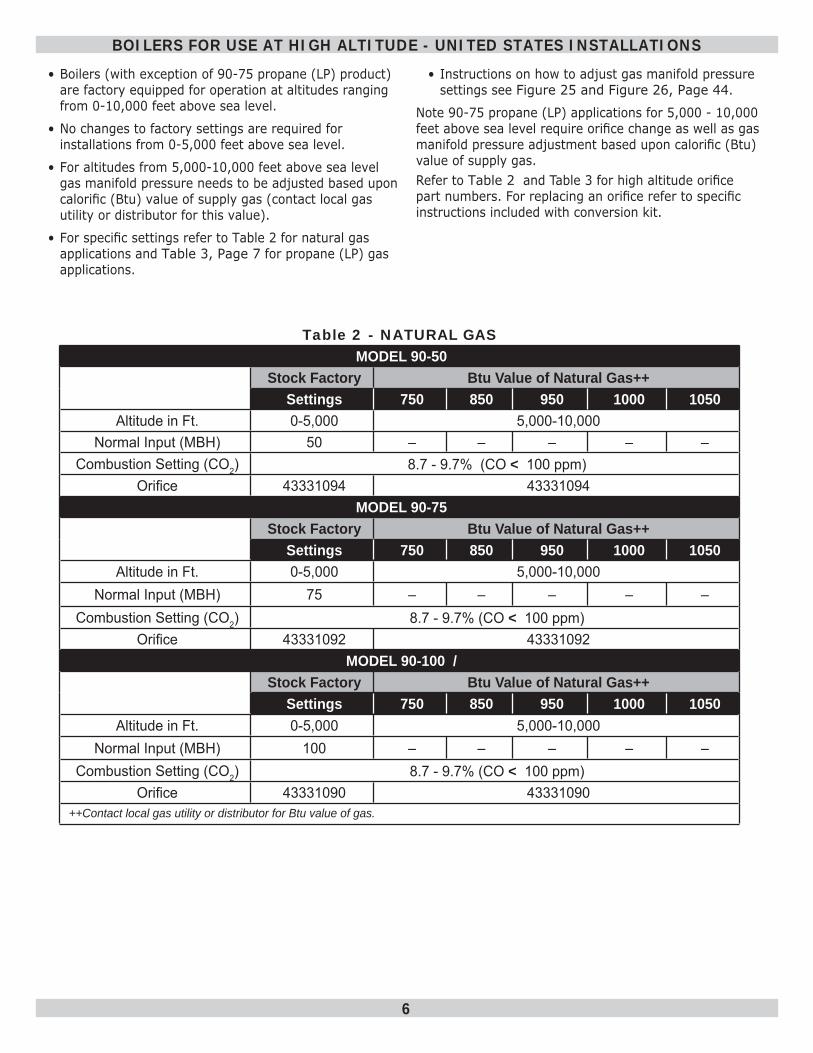
Table 2 - NATURAL GASMODEL 90-50
Stock Factory Btu Value of Natural Gas++Settings 750 850 950 1000 1050
Altitude in Ft. 0-5,000 5,000-10,000Normal Input (MBH) 50 – – – – –
Combustion Setting (CO2) 8.7 - 9.7% (CO < 100 ppm)Orifi ce 43331094 43331094
MODEL 90-75 Stock Factory Btu Value of Natural Gas++
Settings 750 850 950 1000 1050Altitude in Ft. 0-5,000 5,000-10,000
Normal Input (MBH) 75 – – – – –Combustion Setting (CO2) 8.7 - 9.7% (CO < 100 ppm)
Orifi ce 43331092 43331092MODEL 90-100 /
Stock Factory Btu Value of Natural Gas++Settings 750 850 950 1000 1050
Altitude in Ft. 0-5,000 5,000-10,000Normal Input (MBH) 100 – – – – –
Combustion Setting (CO2) 8.7 - 9.7% (CO < 100 ppm)Orifi ce 43331090 43331090
++Contact local gas utility or distributor for Btu value of gas.
BOILERS FOR USE AT HIGH ALTITUDE - UNITED STATES INSTALLATIONS
• Boilers (with exception of 90-75 propane (LP) product) are factory equipped for operation at altitudes ranging from 0-10,000 feet above sea level.
• No changes to factory settings are required for installations from 0-5,000 feet above sea level.
• For altitudes from 5,000-10,000 feet above sea level gas manifold pressure needs to be adjusted based upon calorifi c (Btu) value of supply gas (contact local gas utility or distributor for this value).
• For specifi c settings refer to Table 2 for natural gas applications and Table 3, Page 7 for propane (LP) gas applications.
• Instructions on how to adjust gas manifold pressure settings see Figure 25 and Figure 26, Page 44 .
Note 90-75 propane (LP) applications for 5,000 - 10,000 feet above sea level require orifi ce change as well as gas manifold pressure adjustment based upon calorifi c (Btu) value of supply gas. Refer to Table 2 and Table 3 for high altitude orifi ce part numbers. For replacing an orifi ce refer to specifi c instructions included with conversion kit.
7
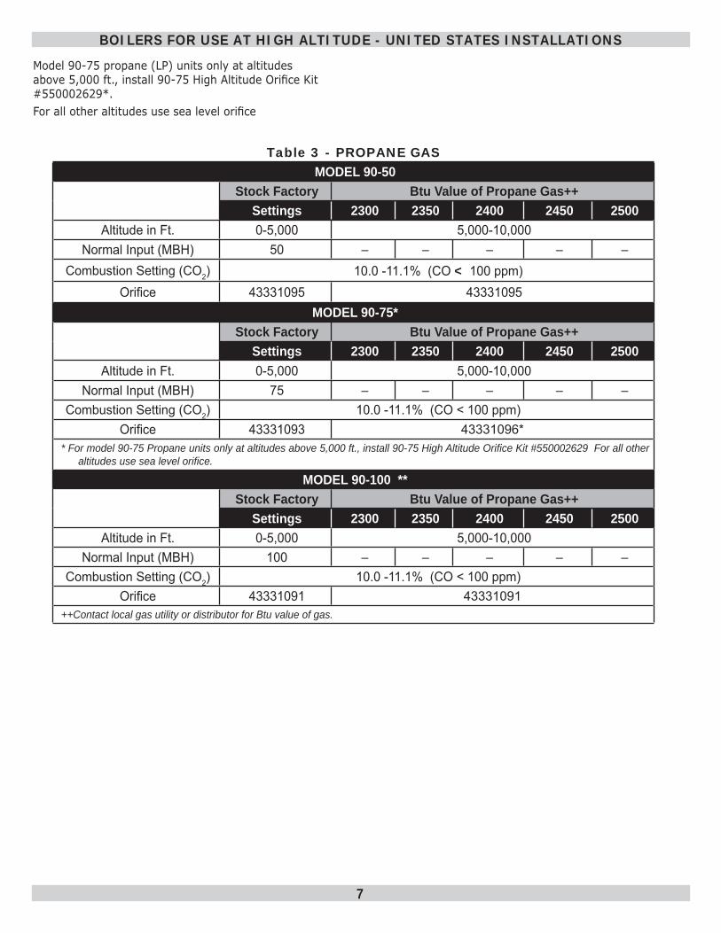
Table 3 - PROPANE GASMODEL 90-50
Stock Factory Btu Value of Propane Gas++Settings 2300 2350 2400 2450 2500
Altitude in Ft. 0-5,000 5,000-10,000Normal Input (MBH) 50 – – – – –
Combustion Setting (CO2) 10.0 -11.1% (CO < 100 ppm)Orifi ce 43331095 43331095
MODEL 90-75* Stock Factory Btu Value of Propane Gas++
Settings 2300 2350 2400 2450 2500Altitude in Ft. 0-5,000 5,000-10,000
Normal Input (MBH) 75 – – – – –Combustion Setting (CO2) 10.0 -11.1% (CO < 100 ppm)
Orifi ce 43331093 43331096** For model 90-75 Propane units only at altitudes above 5,000 ft., install 90-75 High Altitude Orifi ce Kit #550002629 For all other
altitudes use sea level orifi ce.
MODEL 90-100 **Stock Factory Btu Value of Propane Gas++
Settings 2300 2350 2400 2450 2500Altitude in Ft. 0-5,000 5,000-10,000
Normal Input (MBH) 100 – – – – –Combustion Setting (CO2) 10.0 -11.1% (CO < 100 ppm)
Orifi ce 43331091 43331091++Contact local gas utility or distributor for Btu value of gas.
BOILERS FOR USE AT HIGH ALTITUDE - UNITED STATES INSTALLATIONS
Model 90-75 propane (LP) units only at altitudes above 5,000 ft., install 90-75 High Altitude Orifi ce Kit #550002629*. For all other altitudes use sea level orifi ce
8
Boiler Sizing Check to be sure you have selected boiler with proper capacity before starting installation. AHRI Rating of boiler selected should be greater than or equal to calculated peak heating load (heat loss) for building or area(s) served by boiler and associated hot water heating systems. See Table 1, Page 5 . Heat loss calculations should be based on approved industry methods.
Boiler Location ConsiderationsBefore selecting boiler location consider following.
• Supplied with correct type of gas (natural gas or propane).
• Connected to suitable combustion air intake piping system to supply correct amounts of fresh (outdoor) air for combustion, refer to “Combustion Air and Vent Pipe” on page 22 for details.
• Connected to suitable venting system to remove hazardous products of gas combustion, refer to “Combustion Air and Vent Pipe” on page 22 for details.
• Connected to suitable hot water heating system.
• Supplied with suitable electrical supply for all boiler motors and controls.
• Connected to properly located thermostat or operating control. Not included with boiler.
• Placed on level surface.
• Condensate drain line must be pitched down to fl oor drain or external condensate pump with reservoir at ¼” per foot (wood frame or blocks may be used to raise boiler).
1. Boiler is equipped for residential installations. If used for commercial applications, any additional code requirements must be adhered to for installation. This may require additional controls including but not limited to an additional low water cut off, a manual reset high temperature limit, and wiring and/or piping modifi cations.
2. Before servicing boiler - allow boiler to cool. Shut off electricity and gas supply connected to boiler prior to servicing.
3. Inspect gas line for leaks.4. Verify gas input rate is correct. Over fi ring may result
in early failure of boiler sections. This may cause dangerous operation. Under fi ring may result in too much air for pre-mix burner causing poor or loss of combustion.
5. Never vent products of combustion from this boiler to enclosed space. Always vent to outdoors. Never vent to another room or to inside building.
6. Be sure there is adequate outdoor air supply to boiler for complete combustion.
7. Follow regular service and maintenance schedule for effi cient and safe operation.
8. Keep boiler area clean of debris and free of combustible and fl ammable materials.
9. Proper through wall or through roof combustion venting shall be in accordance with materials and methods described in this manual. Installation must comply with local codes.
10. Boiler and related hot water heating systems are not do it yourself items they must be installed and serviced by qualifi ed professionals.
BEFORE INSTALLING THE BOILER
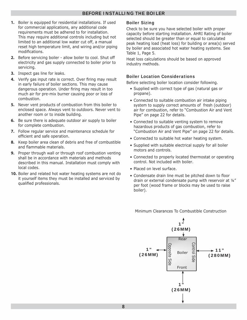
Minimum Clearances To Combustible Construction
8”
Boiler
Rear
Front
Control Side
Opposite Side
1” (26MM)
11”(280MM)
1” (26MM)
1” (26MM)
9
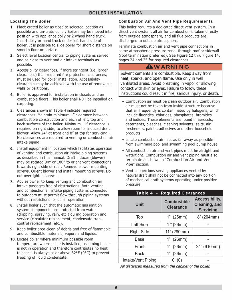
Table 4 - Required Clearances
Unit Combustible Clearance
Accessibility, Cleaning, and
Servicing Top 1” (26mm) 8” (204mm)
Left Side 1 “ (26mm) -Right Side 11” (280mm) -
Base 1” (26mm) -Front 1” (26mm) 24” (610mm)Back 1” (26mm) -
Intake/Vent Piping 0 (0) -All distances measured from the cabinet of the boiler.
Locating The Boiler1. Place crated boiler as close to selected location as
possible and un-crate boiler. Boiler may be moved into position with appliance dolly or 2 wheel hand truck. Insert dolly or hand truck under left hand side of boiler. It is possible to slide boiler for short distance on smooth fl oor or surface.
2. Select level location central to piping systems served and as close to vent and air intake terminals as possible.
3. Accessibility clearances, if more stringent (i.e. larger clearances) than required fi re protection clearances, must be used for boiler installation. Accessibility clearances may be achieved with the use of removable walls or partitions.
4. Boiler is approved for installation in closets and on combustible fl oors. This boiler shall NOT be installed on carpeting.
5. Clearances shown in Table 4 indicate required clearances. Maintain minimum 1” clearance between combustible construction and each of left, top and back surfaces of the boiler. Minimum 11” clearance is required on right side, to allow room for induced draft blower. Allow 24” at front and 8” at top for servicing. No clearances are required to venting or combustion air intake piping.
6. Install equipment in location which facilitates operation of venting and combustion air intake piping systems as described in this manual. Draft inducer (blower) may be rotated 90° or 180° to orient vent connections towards right side or rear. Remove blower mounting screws. Orient blower and install mounting screws. Do not overtighten screws.
7. Advise owner to keep venting and combustion air intake passages free of obstructions. Both venting and combustion air intake piping systems connected to outdoors must permit fl ow through piping systems without restrictions for boiler operation.
8. Install boiler such that the automatic gas ignition system components are protected from water (dripping, spraying, rain, etc.) during operation and service (circulator replacement, condensate trap, control replacement, etc.).
9. Keep boiler area clean of debris and free of fl ammable and combustible materials, vapors and liquids.
10. Locate boiler where minimum possible room temperature where boiler is installed, assuming boiler is not in operation and therefore contributes no heat to space, is always at or above 32°F (0°C) to prevent freezing of liquid condensate.
Combustion Air And Vent Pipe RequirementsThis boiler requires a dedicated direct vent system. In a direct vent system, all air for combustion is taken directly from outside atmosphere, and all fl ue products are discharged to outside atmosphere.Terminate combustion air and vent pipe connections in same atmospheric pressure zone, through roof or sidewall (roof termination preferred). See Figure 12 thru Figure 14 , pages 24 and 25 for required clearances.
WARNINGSolvent cements are combustible. Keep away from heat, sparks, and open fl ame. Use only in well ventilated areas. Avoid breathing in vapor or allowing contact with skin or eyes. Failure to follow these instructions could result in fi re, serious injury, or death.
!
• Combustion air must be clean outdoor air. Combustion air must not be taken from inside structure because that air frequently is contaminated by halogens, which include fl uorides, chlorides, phosphates, bromides and iodides. These elements are found in aerosols, detergents, bleaches, cleaning solvents, salts, air fresheners, paints, adhesives and other household products.
• Locate combustion air inlet as far away as possible from swimming pool and swimming pool pump house.
• All combustion air and vent pipes must be airtight and watertight. Combustion air and vent piping must also terminate as shown in “Combustion Air and Vent Pipe” section.
• Vent connections serving appliances vented by natural draft shall not be connected into any portion of mechanical draft systems operating under positive pressure.
BOILER INSTALLATION
10
Condensate Drain Requirements• Pitch condensate drain line down to fl oor drain at
minimum of ¼” per foot. External condensate pump (not furnished) may be used if fl oor drain is not available. Installation shall conform to requirements of authority having jurisdiction, check local codes for requirements.
• Condensate pump must be designed for fl ue gas condensate application.
• Condensate trap provided with boiler, an additional trap is not required and should not be used.
• Wood frame or blocks may be used to raise boiler to maintain drain pitch or to be above external condensate pump reservoir.
Foundation Requirements• Install boiler on level surface.
WARNINGFire hazard. Do not install boiler on carpeting. Failure to follow these instructions could result in death or serious injury.
!
• Boiler is NOT to be installed on carpeting.
• If boiler is not level condensate drain lines will not function properly. Adjustable feet are located on the boiler to make up for minor surface irregularities or tilt.
• Wood frame or blocks may be used to raise boiler to maintain drain pitch or to be above external condensate pump reservoir.
Removal of Existing Boiler From Common Vent SystemWhen an existing boiler is removed from a common venting system, the common venting system is likely to be too large for proper venting of the appliances remaining connected to it. At the time of removal of an existing boiler, the following steps shall be followed with each appliance remaining connected to the common venting system placed in operation, while the other appliances remaining connected to the common venting system are not in operation.1. Seal any unused openings in the common venting
system.2. Visually inspect the venting system for proper size and
horizontal pitch and determine there is no blockage, or restrictions, leakage, corrosion and other defi ciencies which could cause an unsafe condition.
BOILER INSTALLATION
3. In-so-far as is practical, close all building doors and windows and all doors between the space in which the appliances remaining connected to the common venting system are located and other spaces of the building. Turn on clothes dryer and any appliance not connected to the common venting system. Turn on any exhaust fans, such as range hoods and bathroom exhaust, so they will operate at maximum speed. Do not operate a summer exhaust fan. Close fi re dampers.
4. Place in operation the appliance being inspected. Follow the lighting instructions. Adjust thermostat so appliances will operate continuously.
5. Test for spillage at the draft hood relief opening after 5 minutes of main burner operation. Use the fl ame of a match or candle, or the smoke from a cigarette, cigar or pipe.
6. After it has been determined that each appliance remaining connected to the common venting system properly vents when tested as outlined above, return doors, windows, exhaust fans, fi re place dampers, and any other gas-burning appliance to their previous condition of use.
7. Any improper operation of the common venting system should be corrected so the installation conforms with the National Fuel Code, NFPA-54/ANSI -Z223.1 and/or the Natural Gas and Propane Installation Code, CAN/CSA B149.1. When re-sizing any portion of the common venting system, the common venting system should be re-sized to approach the minimum size as determined using the appropriate of the National Fuel Gas Code, NFPA-54/ANSI- Z223.1 and/or the Natural Gas and Propane Installation Code, CAN/CSA B149.1.
11
Near Boiler Piping• When boiler installation is for new heating system,
install all of radiation units (panels, radiators, baseboard, or tubing) and supply and return mains.
• After all heating system piping and components have been installed, make fi nal connection of system piping to boiler. Hot water boiler installed above radiation level, or as required by the Authority having jurisdiction, must be equipped with low water cut off device.
• Periodic inspection is necessary for fl ushing of fl oat type devices, per low water cut off manufacturers specifi c instructions.
Clean System FirstBefore connecting boiler to heating system, clean and fl ush system thoroughly. Verify system is free of sediment, fl ux and any residual boiler water additives.
Systems having antifreeze not recommended must be completely fl ushed to insure no old antifreeze remains. In older systems obviously discolored, murky or dirty water; or pH reading outside acceptable range (between 7.0 and 8.0) are indications the system should be cleaned or treated. Thoroughly fl ush system with clean water to remove any sediment or contaminants. Sludge and iron oxide deposits can cause rapid breakdown of inhibitors.
Flushing with clean water. If chemical cleaners are used, use only those recommended for use with aluminum boilers. Follow chemical cleaner manufacturer’s instructions completely. DO NOT mix different manufacturer’s products.
NEAR BOILER PIPING
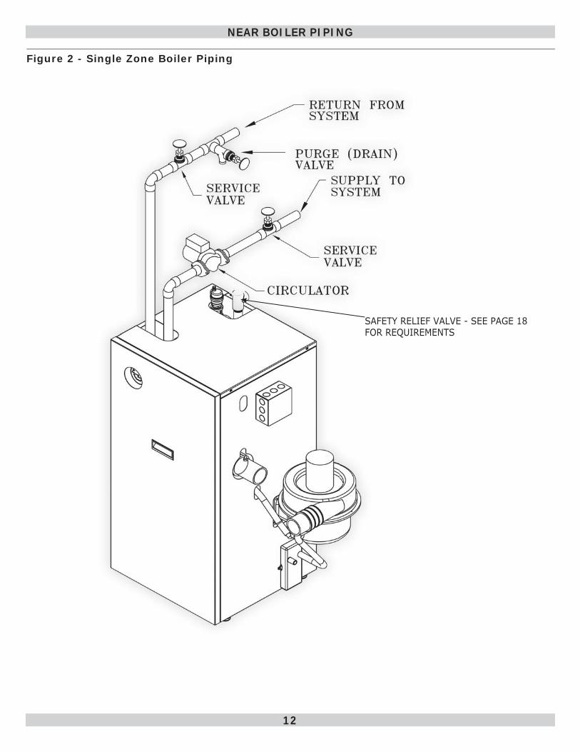
Supply And Return Lines• Boiler is set up to receive 1¼” NPT supply and return
piping from top access.
• Boiler may be piped from left side by turning supply elbow.
• Install furnished dielectric unions at boiler supply and return lines prior to making system piping connections
• Do not install copper supply and return piping directly into aluminum boiler section casings due to galvanic corrosion between dissimilar metals.
• Must use provided dielectric unions between copper system piping and boiler to make fi nal connection to boiler.
• Circulator pump can be installed at installer preferred location.
12
NEAR BOILER PIPING
Figure 2 - Single Zone Boiler Piping
SAFETY RELIEF VALVE - SEE PAGE 18 FOR REQUIREMENTS
13
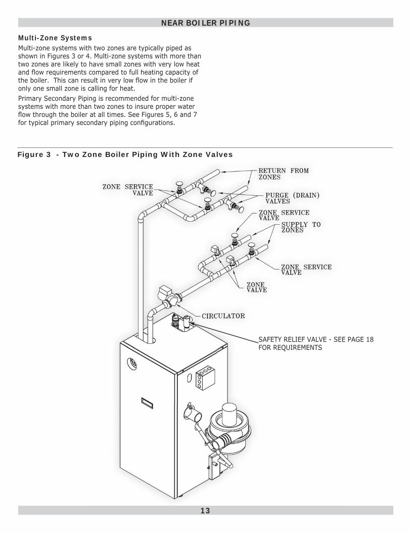
Figure 3 - Two Zone Boiler Piping With Zone Valves
NEAR BOILER PIPING
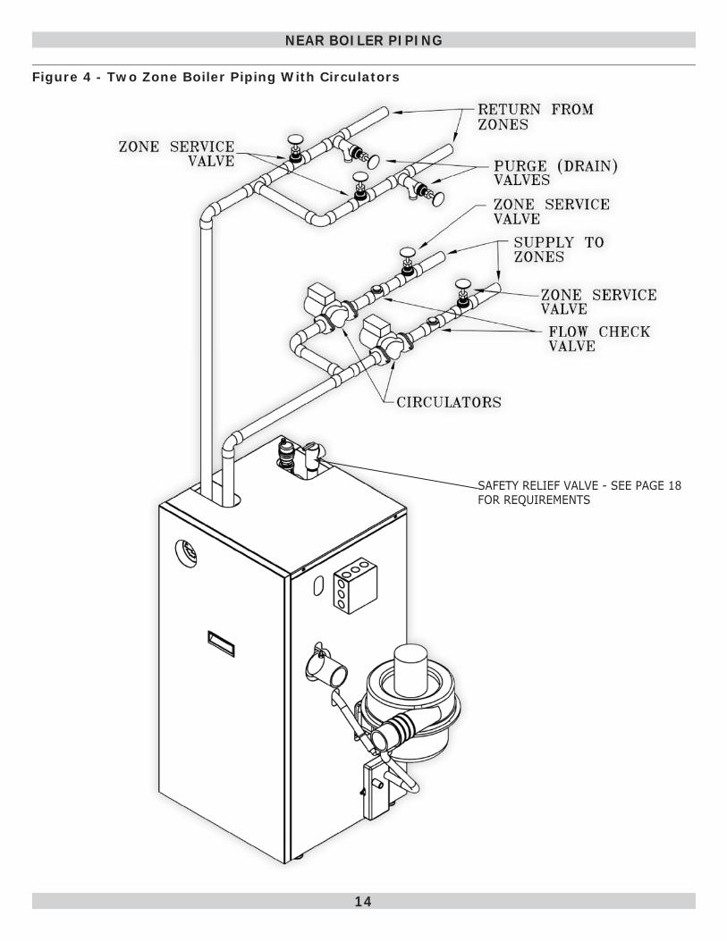
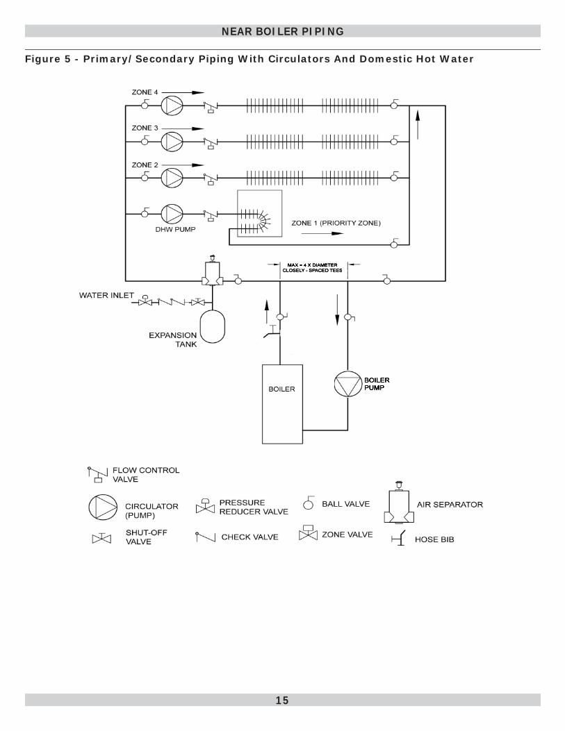
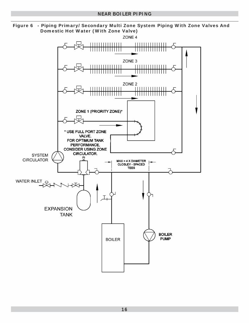
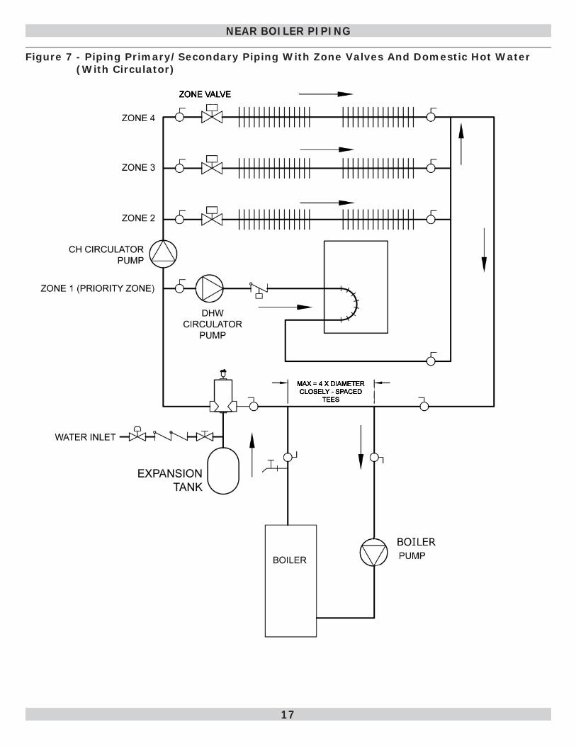
Multi-Zone SystemsMulti-zone systems with two zones are typically piped as shown in Figures 3 or 4. Multi-zone systems with more than two zones are likely to have small zones with very low heat and fl ow requirements compared to full heating capacity of the boiler. This can result in very low fl ow in the boiler if only one small zone is calling for heat. Primary Secondary Piping is recommended for multi-zone systems with more than two zones to insure proper water fl ow through the boiler at all times. See Figures 5, 6 and 7 for typical primary secondary piping confi gurations.
SAFETY RELIEF VALVE - SEE PAGE 18 FOR REQUIREMENTS
14
Figure 4 - Two Zone Boiler Piping With Circulators
NEAR BOILER PIPING
SAFETY RELIEF VALVE - SEE PAGE 18 FOR REQUIREMENTS
15
NEAR BOILER PIPING
Figure 5 - Primary/Secondary Piping With Circulators And Domestic Hot Water
16
NEAR BOILER PIPING
Figure 6 - Piping Primary/Secondary Multi Zone System Piping With Zone Valves And Domestic Hot Water (With Zone Valve)
17
NEAR BOILER PIPING
Figure 7 - Piping Primary/Secondary Piping With Zone Valves And Domestic Hot Water (With Circulator)
18
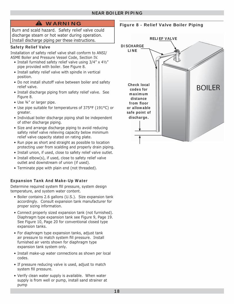
Safety Relief ValveInstallation of safety relief valve shall conform to ANSI/ASME Boiler and Pressure Vessel Code, Section IV.
• Install furnished safety relief valve using 3/4” x 4½” pipe provided with boiler. See Figure 8 .
• Install safety relief valve with spindle in vertical position.
• Do not install shutoff valve between boiler and safety relief valve.
• Install discharge piping from safety relief valve. See Figure 8 .
• Use ¾” or larger pipe.• Use pipe suitable for temperatures of 375°F (191°C) or
greater.• Individual boiler discharge piping shall be independent
of other discharge piping.• Size and arrange discharge piping to avoid reducing
safety relief valve relieving capacity below minimum relief valve capacity stated on rating plate.
• Run pipe as short and straight as possible to location protecting user from scalding and properly drain piping.
• Install union, if used, close to safety relief valve outlet.• Install elbow(s), if used, close to safety relief valve
outlet and downstream of union (if used).• Terminate pipe with plain end (not threaded).
Expansion Tank And Make-Up WaterDetermine required system fi ll pressure, system design temperature, and system water content.
• Boiler contains 2.6 gallons (U.S.). Size expansion tank accordingly. Consult expansion tank manufacturer for proper sizing information.
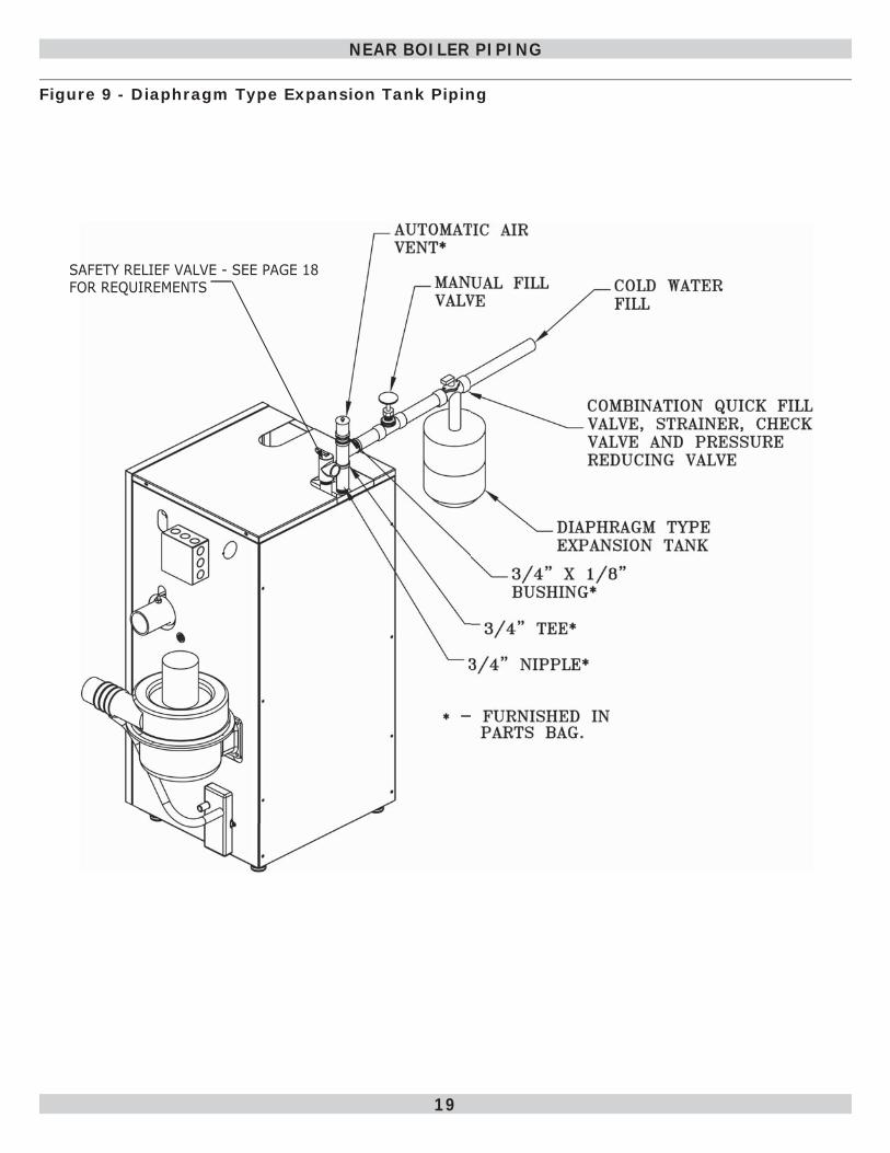
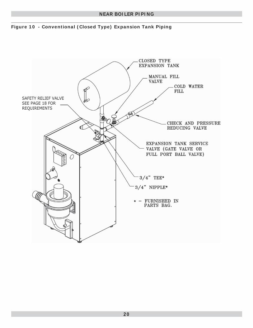
• Connect properly sized expansion tank (not furnished). Diaphragm type expansion tank see Figure 9, Page 19 . See Figure 10, Page 20 for conventional closed type expansion tanks.
• For diaphragm type expansion tanks, adjust tank air pressure to match system fi ll pressure. Install furnished air vents shown for diaphragm type expansion tank system only.
• Install make-up water connections as shown per local codes.
• If pressure reducing valve is used, adjust to match system fi ll pressure.
• Verify clean water supply is available. When water supply is from well or pump, install sand strainer at pump
Figure 8 - Relief Valve Boiler Piping
NEAR BOILER PIPING
RELIEF VALVE
DISCHARGE LINE
Check local codes for maximum distance
from fl oor or allowable safe point of discharge.
WARNINGBurn and scald hazard. Safety relief valve could discharge steam or hot water during operation. Install discharge piping per these instructions.
!
19
Figure 9 - Diaphragm Type Expansion Tank Piping
NEAR BOILER PIPING
SAFETY RELIEF VALVE - SEE PAGE 18 FOR REQUIREMENTS
20
Figure 10 - Conventional (Closed Type) Expansion Tank Piping
NEAR BOILER PIPING
SAFETY RELIEF VALVE SEE PAGE 18 FOR REQUIREMENTS
21
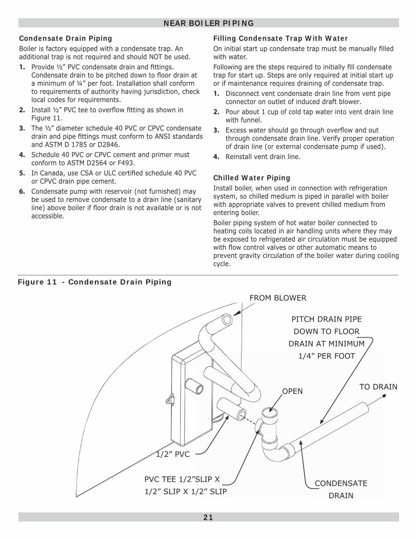
Condensate Drain PipingBoiler is factory equipped with a condensate trap. An additional trap is not required and should NOT be used.1. Provide ½” PVC condensate drain and fi ttings.
Condensate drain to be pitched down to fl oor drain at a minimum of ¼” per foot. Installation shall conform to requirements of authority having jurisdiction, check local codes for requirements.
2. Install ½” PVC tee to overfl ow fi tting as shown in Figure 11 .
3. The ½” diameter schedule 40 PVC or CPVC condensate drain and pipe fi ttings must conform to ANSI standards and ASTM D 1785 or D2846.
4. Schedule 40 PVC or CPVC cement and primer must conform to ASTM D2564 or F493.
5. In Canada, use CSA or ULC certifi ed schedule 40 PVC or CPVC drain pipe cement.
6. Condensate pump with reservoir (not furnished) may be used to remove condensate to a drain line (sanitary line) above boiler if fl oor drain is not available or is not accessible.
Figure 11 - Condensate Drain Piping
NEAR BOILER PIPING
Filling Condensate Trap With Water On initial start up condensate trap must be manually fi lled with water.Following are the steps required to initially fi ll condensate trap for start up. Steps are only required at initial start up or if maintenance requires draining of condensate trap.1. Disconnect vent condensate drain line from vent pipe
connector on outlet of induced draft blower.2. Pour about 1 cup of cold tap water into vent drain line
with funnel.3. Excess water should go through overfl ow and out
through condensate drain line. Verify proper operation of drain line (or external condensate pump if used).
4. Reinstall vent drain line.
Chilled Water PipingInstall boiler, when used in connection with refrigeration system, so chilled medium is piped in parallel with boiler with appropriate valves to prevent chilled medium from entering boiler.Boiler piping system of hot water boiler connected to heating coils located in air handling units where they may be exposed to refrigerated air circulation must be equipped with fl ow control valves or other automatic means to prevent gravity circulation of the boiler water during cooling cycle.
FROM BLOWER
TO DRAINOPEN
PVC TEE 1/2”SLIP X 1/2” SLIP X 1/2” SLIP
1/2” PVC
CONDENSATE DRAIN
PITCH DRAIN PIPE DOWN TO FLOOR
DRAIN AT MINIMUM 1/4” PER FOOT
22
Connections And TerminationProvisions for combustion and ventilation air must be in accordance with section, Air For Combustion and Ventilation, of the National Fuel Gas Code,ANSI 2223.1/NFPA54, or National Gas and Propane Installation Code, CAN/CGA-B 149.1, or applicable provisions of the local building code.Boilers require dedicated direct vent system. All air for combustion is taken directly from outdoors through combustion air intake pipe. All fl ue products are discharged to outdoors through vent pipe.1. Venting Materials:
WARNINGUse of cellular core PVC (ASTM F891), cellular core CPVC, or Radel® ,(Polyphenolsulfone) in venting systems could result in death, or serious injury.
!
WARNINGCovering non-metallic vent pipe and fi ttings with thermal insulation shall be prohibited. Use in venting system could result in death or serious injury.
!
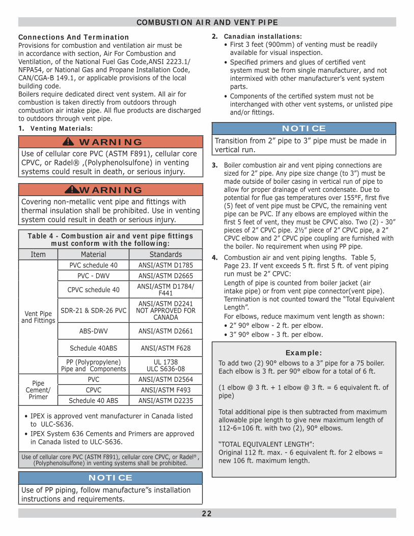
Table 4 - Combustion air and vent pipe fi ttings must conform with the following:
Item Material Standards
Vent Pipe and Fittings
PVC schedule 40 ANSI/ASTM D1785PVC - DWV ANSI/ASTM D2665
CPVC schedule 40 ANSI/ASTM D1784/F441
SDR-21 & SDR-26 PVCANSI/ASTM D2241
NOT APPROVED FOR CANADA
ABS-DWV ANSI/ASTM D2661
Schedule 40ABS ANSI/ASTM F628
PP (Polypropylene)Pipe and Components
UL 1738ULC S636-08
Pipe Cement/Primer
PVC ANSI/ASTM D2564CPVC ANSI/ASTM F493
Schedule 40 ABS ANSI/ASTM D2235
• IPEX is approved vent manufacturer in Canada listed to ULC-S636.
• IPEX System 636 Cements and Primers are approved in Canada listed to ULC-S636.
Use of cellular core PVC (ASTM F891), cellular core CPVC, or Radel® ,(Polyphenolsulfone) in venting systems shall be prohibited.
2. Canadian installations:• First 3 feet (900mm) of venting must be readily
available for visual inspection. • Specifi ed primers and glues of certifi ed vent
system must be from single manufacturer, and not intermixed with other manufacturer’s vent system parts.
• Components of the certifi ed system must not be interchanged with other vent systems, or unlisted pipe and/or fi ttings.
NOTICETransition from 2” pipe to 3” pipe must be made in vertical run.
3. Boiler combustion air and vent piping connections are sized for 2” pipe. Any pipe size change (to 3”) must be made outside of boiler casing in vertical run of pipe to allow for proper drainage of vent condensate. Due to potential for fl ue gas temperatures over 155°F, fi rst fi ve (5) feet of vent pipe must be CPVC, the remaining vent pipe can be PVC. If any elbows are employed within the fi rst 5 feet of vent, they must be CPVC also. Two (2) - 30” pieces of 2” CPVC pipe. 2½” piece of 2” CPVC pipe, a 2” CPVC elbow and 2” CPVC pipe coupling are furnished with the boiler. No requirement when using PP pipe.
4. Combustion air and vent piping lengths. Table 5, Page 23 . If vent exceeds 5 ft. fi rst 5 ft. of vent piping run must be 2” CPVC:Length of pipe is counted from boiler jacket (air intake pipe) or from vent pipe connector(vent pipe). Termination is not counted toward the “Total Equivalent Length”. For elbows, reduce maximum vent length as shown: • 2” 90° elbow - 2 ft. per elbow. • 3” 90° elbow - 3 ft. per elbow.
Example: To add two (2) 90° elbows to a 3” pipe for a 75 boiler.Each elbow is 3 ft. per 90° elbow for a total of 6 ft.
(1 elbow @ 3 ft. + 1 elbow @ 3 ft. = 6 equivalent ft. of pipe)
Total additional pipe is then subtracted from maximum allowable pipe length to give new maximum length of 112-6=106 ft. with two (2), 90° elbows.
“TOTAL EQUIVALENT LENGTH”:Original 112 ft. max. - 6 equivalent ft. for 2 elbows = new 106 ft. maximum length.
COMBUSTION AIR AND VENT PIPE
NOTICEUse of PP piping, follow manufacture”s installation instructions and requirements.
23
5. See Figure 12 thru Figure 17, Pages 24 thru 26 for combustion air and vent pipe roof and sidewall termination. Roof termination is preferred. Combustion air and vent pipes must terminate together in same atmospheric pressure zone as shown.
6. Construction through which vent and air intake pipes may be installed is maximum 24 inches, minimum ¼” thickness.
7. Optional- Rotate draft inducer (blower) 90° or 180° to orient vent connection towards right side or rear. Remove blower mounting screws, re-orient blower. Reinstall mounting screws. Do not overtighten screws.
8. Pitch combustion air and vent piping back to boiler at minimum ¼” per ft. (21 mm/m) from intake and vent terminals so all moisture in combustion air and vent piping drains to boiler. Pitch pipes continuously with no sags or low spots where moisture can accumulate and block fl ow of air or fl ue gas. Combustion air and vent pipes must be airtight and watertight.
9. Consider following when determining appropriate location for termination of combustion air and vent piping.
• Position termination where vent vapors will not damage plants/shrubs or air conditioning equipment.
• Position termination as to not be effected by wind eddy, air born leaves, snow, or recirculated fl ue gases.
• Position termination where it will not be subjected to potential damage by foreign objects, such as stones, balls, etc..
• Position termination should where vent vapors are not objectionable.
• Place vent on wall away from prevailing wind. Locate or guard vent to prevent accidental contact with people or pets.
• Terminate vent above normal snow line. Avoid locations where snow may drift and block vent. Ice or snow may cause boiler to shut down if vent becomes obstructed.
• Under certain conditions, fl ue gas will condense, forming moisture, and may be corrosive. Take steps to prevent building materials at vent from being damaged by exhaust of fl ue gas.
• Vent shall not terminate where it may cause hazardous frost or ice accumulations on adjacent property surfaces.
10. Venting Requirements:• Venting system shall terminate at least 3 ft. (0.9m)
above any forced air inlet (except boiler’s combustion air inlet) within 10 ft.(3m).
COMBUSTION AIR AND VENT PIPE
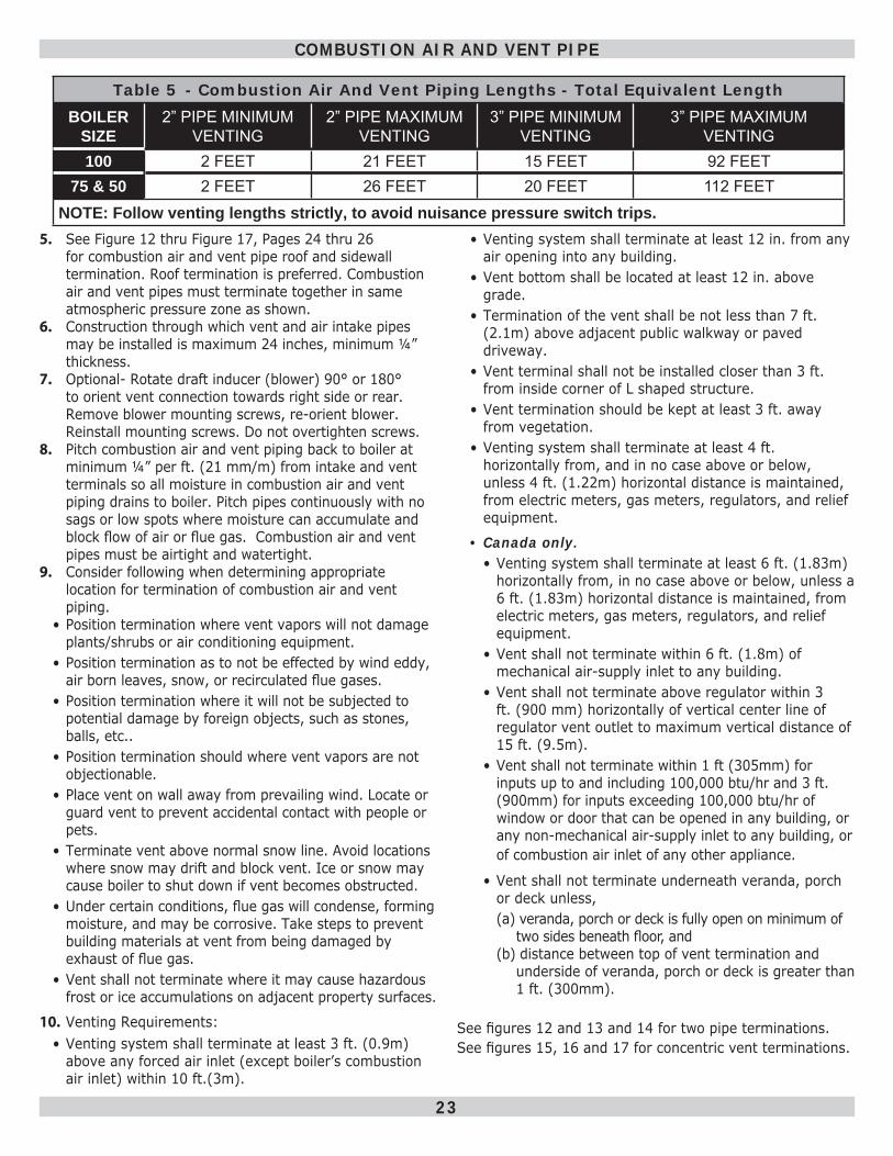
Table 5 - Combustion Air And Vent Piping Lengths - Total Equivalent LengthBOILER
SIZE2” PIPE MINIMUM
VENTING2” PIPE MAXIMUM
VENTING3” PIPE MINIMUM
VENTING3” PIPE MAXIMUM
VENTING100 2 FEET 21 FEET 15 FEET 92 FEET
75 & 50 2 FEET 26 FEET 20 FEET 112 FEET NOTE: Follow venting lengths strictly, to avoid nuisance pressure switch trips.
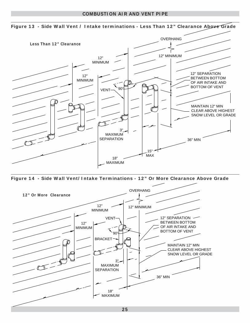
• Venting system shall terminate at least 12 in. from any air opening into any building.
• Vent bottom shall be located at least 12 in. above grade.
• Termination of the vent shall be not less than 7 ft. (2.1m) above adjacent public walkway or paved driveway.
• Vent terminal shall not be installed closer than 3 ft. from inside corner of L shaped structure.
• Vent termination should be kept at least 3 ft. away from vegetation.
• Venting system shall terminate at least 4 ft. horizontally from, and in no case above or below, unless 4 ft. (1.22m) horizontal distance is maintained, from electric meters, gas meters, regulators, and relief equipment.
• Canada only. • Venting system shall terminate at least 6 ft. (1.83m)
horizontally from, in no case above or below, unless a 6 ft. (1.83m) horizontal distance is maintained, from electric meters, gas meters, regulators, and relief equipment.
• Vent shall not terminate within 6 ft. (1.8m) of mechanical air-supply inlet to any building.
• Vent shall not terminate above regulator within 3 ft. (900 mm) horizontally of vertical center line of regulator vent outlet to maximum vertical distance of 15 ft. (9.5m).
• Vent shall not terminate within 1 ft (305mm) for inputs up to and including 100,000 btu/hr and 3 ft. (900mm) for inputs exceeding 100,000 btu/hr of window or door that can be opened in any building, or any non-mechanical air-supply inlet to any building, or of combustion air inlet of any other appliance.
• Vent shall not terminate underneath veranda, porch or deck unless, (a) veranda, porch or deck is fully open on minimum of
two sides beneath fl oor, and (b) distance between top of vent termination and
underside of veranda, porch or deck is greater than 1 ft. (300mm).
See fi gures 12 and 13 and 14 for two pipe terminations. See fi gures 15, 16 and 17 for concentric vent terminations.
24
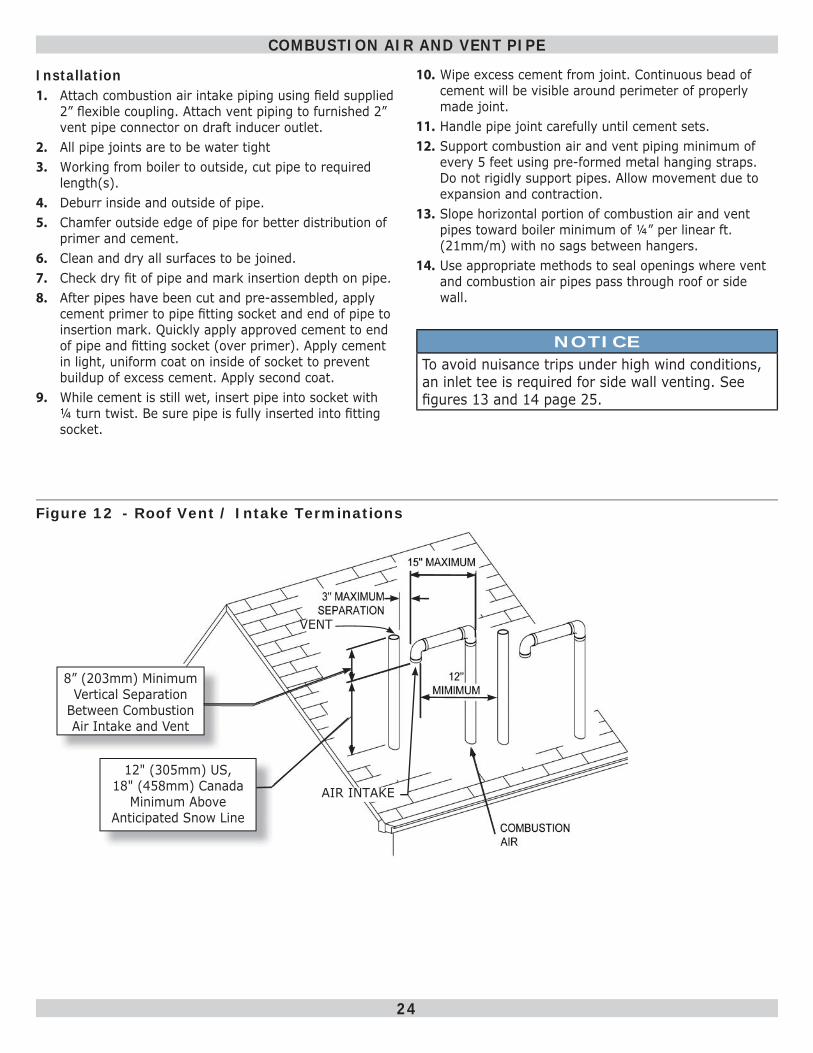
Figure 12 - Roof Vent / Intake Terminations
Installation1. Attach combustion air intake piping using fi eld supplied
2” fl exible coupling. Attach vent piping to furnished 2” vent pipe connector on draft inducer outlet.
2. All pipe joints are to be water tight3. Working from boiler to outside, cut pipe to required
length(s).4. Deburr inside and outside of pipe.5. Chamfer outside edge of pipe for better distribution of
primer and cement.6. Clean and dry all surfaces to be joined.7. Check dry fi t of pipe and mark insertion depth on pipe.8. After pipes have been cut and pre-assembled, apply
cement primer to pipe fi tting socket and end of pipe to insertion mark. Quickly apply approved cement to end of pipe and fi tting socket (over primer). Apply cement in light, uniform coat on inside of socket to prevent buildup of excess cement. Apply second coat.
9. While cement is still wet, insert pipe into socket with ¼ turn twist. Be sure pipe is fully inserted into fi tting socket.
COMBUSTION AIR AND VENT PIPE
VENT
AIR INTAKE
12” (305mm)/18”12” (305mm)/18”
12" (305mm) US, 18" (458mm) Canada
Minimum Above Anticipated Snow Line
8” (203mm) Minimum Vertical Separation
Between Combustion Air Intake and Vent
10. Wipe excess cement from joint. Continuous bead of cement will be visible around perimeter of properly made joint.
11. Handle pipe joint carefully until cement sets.12. Support combustion air and vent piping minimum of
every 5 feet using pre-formed metal hanging straps. Do not rigidly support pipes. Allow movement due to expansion and contraction.
13. Slope horizontal portion of combustion air and vent pipes toward boiler minimum of ¼” per linear ft. (21mm/m) with no sags between hangers.
14. Use appropriate methods to seal openings where vent and combustion air pipes pass through roof or side wall.
NOTICETo avoid nuisance trips under high wind conditions, an inlet tee is required for side wall venting. See fi gures 13 and 14 page 25.
25
Figure 13 - Side Wall Vent / Intake terminations - Less Than 12” Clearance Above Grade
Figure 14 - Side Wall Vent/Intake Terminations - 12” Or More Clearance Above Grade
COMBUSTION AIR AND VENT PIPE
Less Than 12” Clearance
12” Or More Clearance
OVERHANG
12"�MINIMUM
90°VENT
12"�SEPARATION
BETWEEN�BOTTOM�
OF�AIR�INTAKE�AND�
BOTTOM�OF�VENT
MAINTAIN�12"�MIN�
CLEAR�ABOVE�HIGHEST�
SNOW�LEVEL�OR�GRADE
3"
MAXIMUM
�SEPARATION
18"�
MAXIMUM
15"�
MAX
12"
MINIMUM
12"
MINIMUM
36"�MIN
90°
BRACKET
VENT
18"�
MAXIMUM
MAINTAIN�12"�MIN�
CLEAR�ABOVE�HIGHEST�
SNOW�LEVEL�OR�GRADE
12"�SEPARATION
BETWEEN�BOTTOM�
OF�AIR�INTAKE�AND�
BOTTOM�OF�VENT
12"�MINIMUM
OVERHANG
3"
MAXIMUM
�SEPARATION
12"
MINIMUM
12"
MINIMUM
36"�MIN
26
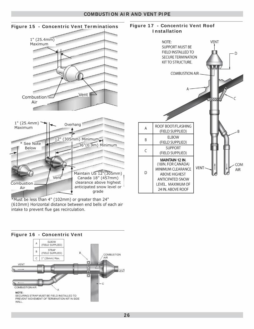
Figure 15 - Concentric Vent Terminations
Combustion Air
Vent
1" (25.4mm) Maximum
Maintain 12" clearance above
highest anticipated snow level or grade
* See Note Below
VentCombustion
Air
36"(0.9m) Minimum
Maintain US 12"(305mm) Canada 18” (457mm)
clearance above highest anticipated snow level or
grade
12" (305mm) Minimum
*Must be less than 4" (102mm) or greater than 24" (610mm) Horizontal distance between end bells of each air intake to prevent fl ue gas recirculation.
1" (25.4mm) Maximum
Overhang
Figure 16 - Concentric Vent
COMBUSTION AIR AND VENT PIPE
Figure 17 - Concentric Vent Roof Installation
A ELBOW (FIELD SUPPLIED)
B STRAP (FIELD SUPPLIED)
C 1” (26mm) Max.
27
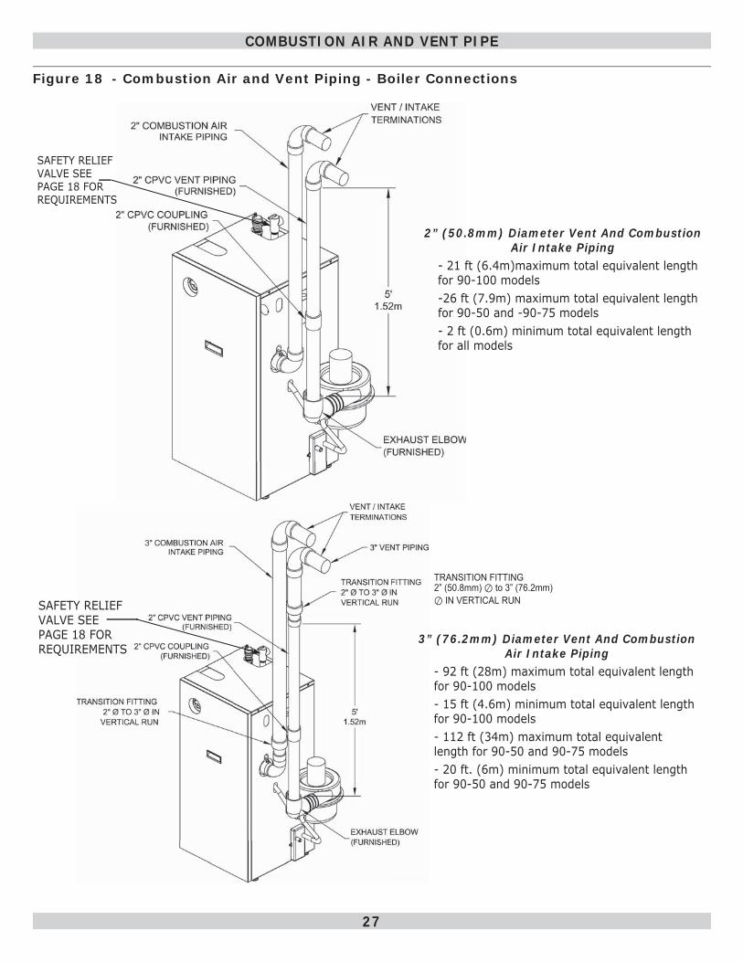
Figure 18 - Combustion Air and Vent Piping - Boiler Connections
COMBUSTION AIR AND VENT PIPE
2” (50.8mm) Diameter Vent And Combustion Air Intake Piping
- 21 ft (6.4m)maximum total equivalent length for 90-100 models-26 ft (7.9m) maximum total equivalent length for 90-50 and -90-75 models- 2 ft (0.6m) minimum total equivalent length for all models
TRANSITION FITTING 2” (50.8mm) ⊘ to 3” (76.2mm) ⊘ IN VERTICAL RUN
3” (76.2mm) Diameter Vent And Combustion Air Intake Piping
- 92 ft (28m) maximum total equivalent length for 90-100 models- 15 ft (4.6m) minimum total equivalent length for 90-100 models- 112 ft (34m) maximum total equivalent length for 90-50 and 90-75 models- 20 ft. (6m) minimum total equivalent length for 90-50 and 90-75 models
SAFETY RELIEF VALVE SEE PAGE 18 FOR REQUIREMENTS
3”
SAFETY RELIEF VALVE SEE PAGE 18 FOR REQUIREMENTS
28
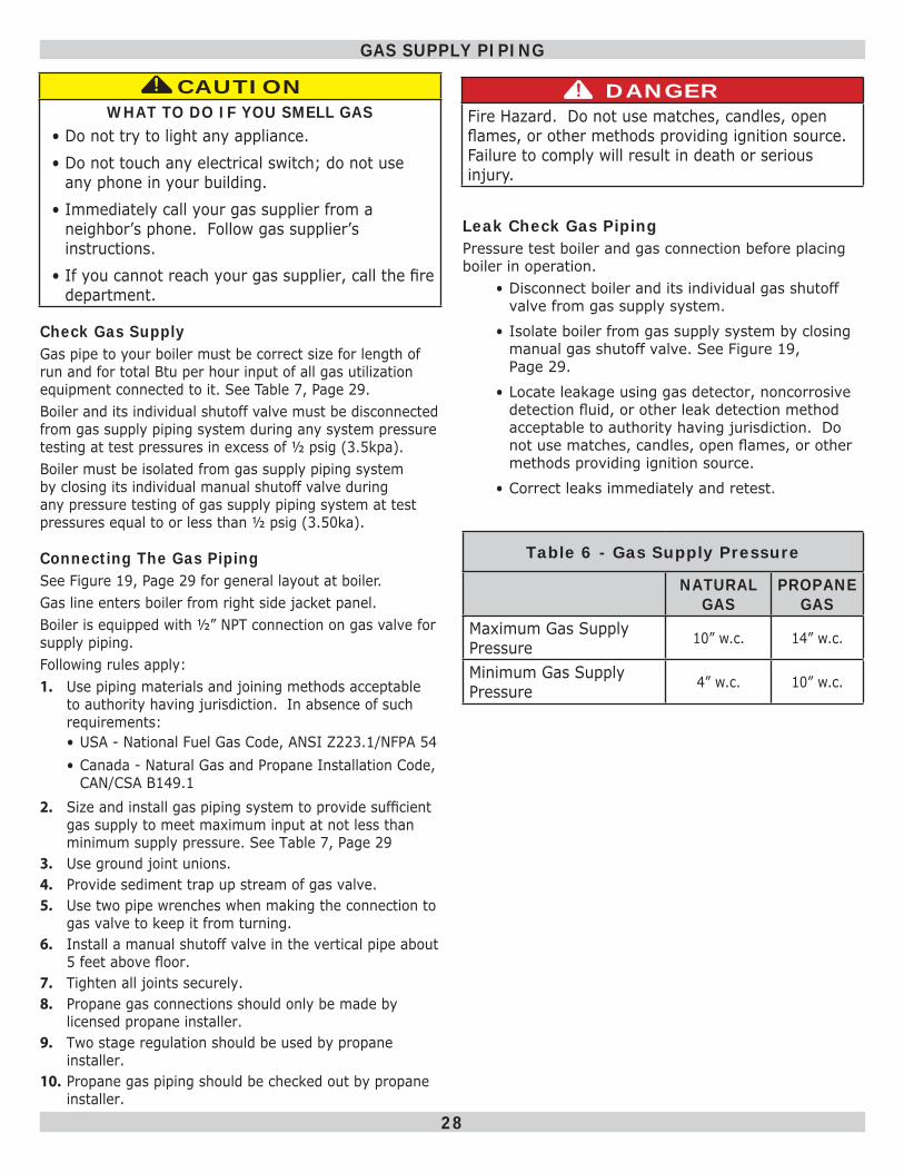
Check Gas SupplyGas pipe to your boiler must be correct size for length of run and for total Btu per hour input of all gas utilization equipment connected to it. See Table 7, Page 29 . Boiler and its individual shutoff valve must be disconnected from gas supply piping system during any system pressure testing at test pressures in excess of ½ psig (3.5kpa).Boiler must be isolated from gas supply piping system by closing its individual manual shutoff valve during any pressure testing of gas supply piping system at test pressures equal to or less than ½ psig (3.50ka).
Table 6 - Gas Supply Pressure
NATURAL GAS
PROPANE GAS
Maximum Gas Supply Pressure 10” w.c. 14” w.c.
Minimum Gas Supply Pressure 4” w.c. 10” w.c.
GAS SUPPLY PIPING
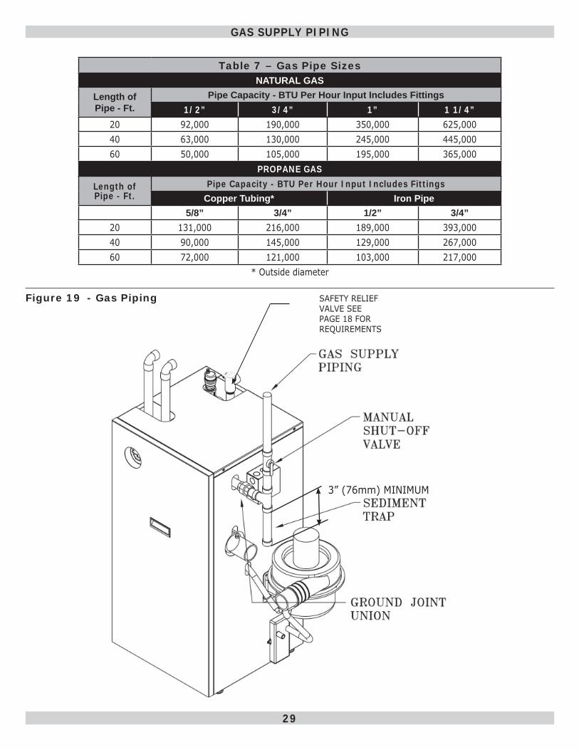
Connecting The Gas PipingSee Figure 19, Page 29 for general layout at boiler. Gas line enters boiler from right side jacket panel. Boiler is equipped with ½” NPT connection on gas valve for supply piping. Following rules apply:1. Use piping materials and joining methods acceptable
to authority having jurisdiction. In absence of such requirements:• USA - National Fuel Gas Code, ANSI Z223.1/NFPA 54• Canada - Natural Gas and Propane Installation Code,
CAN/CSA B149.12. Size and install gas piping system to provide suffi cient
gas supply to meet maximum input at not less than minimum supply pressure. See Table 7, Page 29
3. Use ground joint unions.4. Provide sediment trap up stream of gas valve.5. Use two pipe wrenches when making the connection to
gas valve to keep it from turning.6. Install a manual shutoff valve in the vertical pipe about
5 feet above fl oor. 7. Tighten all joints securely.8. Propane gas connections should only be made by
licensed propane installer.9. Two stage regulation should be used by propane
installer.10. Propane gas piping should be checked out by propane
installer.
CAUTIONWHAT TO DO IF YOU SMELL GAS
• Do not try to light any appliance.• Do not touch any electrical switch; do not use
any phone in your building.• Immediately call your gas supplier from a
neighbor’s phone. Follow gas supplier’s instructions.
• If you cannot reach your gas supplier, call the fi re department.
!! DANGERFire Hazard. Do not use matches, candles, open fl ames, or other methods providing ignition source. Failure to comply will result in death or serious injury.
!
Leak Check Gas PipingPressure test boiler and gas connection before placing boiler in operation.
• Disconnect boiler and its individual gas shutoff valve from gas supply system.
• Isolate boiler from gas supply system by closing manual gas shutoff valve. See Figure 19, Page 29 .
• Locate leakage using gas detector, noncorrosive detection fl uid, or other leak detection method acceptable to authority having jurisdiction. Do not use matches, candles, open fl ames, or other methods providing ignition source.
• Correct leaks immediately and retest.
29
Table 7 – Gas Pipe Sizes NATURAL GAS
Length of Pipe - Ft.
Pipe Capacity - BTU Per Hour Input Includes Fittings1/2” 3/4” 1” 1 1/4”
20 92,000 190,000 350,000 625,00040 63,000 130,000 245,000 445,00060 50,000 105,000 195,000 365,000
PROPANE GAS
Length of Pipe - Ft.
Pipe Capacity - BTU Per Hour Input Includes FittingsCopper Tubing* Iron Pipe
5/8” 3/4” 1/2” 3/4”20 131,000 216,000 189,000 393,00040 90,000 145,000 129,000 267,00060 72,000 121,000 103,000 217,000
* Outside diameter
GAS SUPPLY PIPING
Figure 19 - Gas Piping
3” (76mm) MINIMUM
SAFETY RELIEF VALVE SEE PAGE 18 FOR REQUIREMENTS
30
Electrically bond boiler to ground in accordance with requirements of authority having jurisdiction. Refer to:• USA- National Electrical Code, ANSI/NFPA 70.• Canada - Canadian Electrical Code, Part I, CSA C22.1:
Safety Standard for Electrical Installations.
Electric Power SupplyPrior to making any line Voltage connections, turn OFf electrical power at fuse box.1. Run separate 115 Volt circuit from separate over
current protection device in electrical service entrance panel. This should be 15 ampere circuit.
2. See Figure 20, Page 31 for diagram showing service switch junction box and power supply connection points.
3. Locate service switch in vicinity of boiler. Verify it is turned OFF during service or maintenance.• Connect black (hot) lead from power supply to black
wire labeled L 120 VAC.
• Connect white (neutral) lead from power supply to white wire labeled N 120 VAC.
• Connect green (ground) lead from power supply to green wire labeled G 120 VAC.
4. Run 14 gauge or heavier copper wire from boiler to grounded connection in service panel or properly driven and electrically grounded ground rod.
ELECTRICAL WIRING
Thermostat Installation• Thermostat location has important effect on operation
of boiler system.
• Follow instructions included with your thermostat.
• Locate thermostat about fi ve feet above fl oor on inside wall.
• Mount directly on wall or on vertical mounted outlet box.
• It should be sensing average room temperature.
Set heat anticipator (where applicable) at 0.7 amps. Connect 24 Volt thermostat leads to two(2) yellow wires located in junction box, located on outer jacket of boiler. See Figure 20, Page 31 for junction box and thermostat fi eld wiring connections.
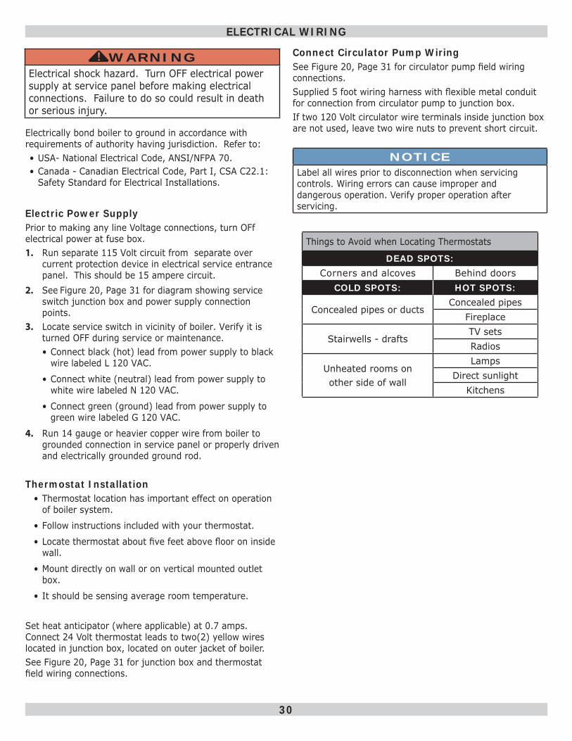
Things to Avoid when Locating Thermostats
DEAD SPOTS:Corners and alcoves Behind doors
COLD SPOTS: HOT SPOTS:
Concealed pipes or ductsConcealed pipes
Fireplace
Stairwells - draftsTV setsRadios
Unheated rooms onother side of wall
LampsDirect sunlight
Kitchens
Connect Circulator Pump WiringSee Figure 20, Page 31 for circulator pump fi eld wiring connections. Supplied 5 foot wiring harness with fl exible metal conduit for connection from circulator pump to junction box. If two 120 Volt circulator wire terminals inside junction box are not used, leave two wire nuts to prevent short circuit.
WARNINGElectrical shock hazard. Turn OFF electrical power supply at service panel before making electrical connections. Failure to do so could result in death or serious injury.
!
NOTICELabel all wires prior to disconnection when servicing controls. Wiring errors can cause improper and dangerous operation. Verify proper operation after servicing.

31
Figure 20 - Field Wiring Connections
ELECTRICAL WIRING
SAFETY RELIEF VALVE SEE PAGE 18 FOR REQUIREMENTS
32
ELECTRICAL WIRING
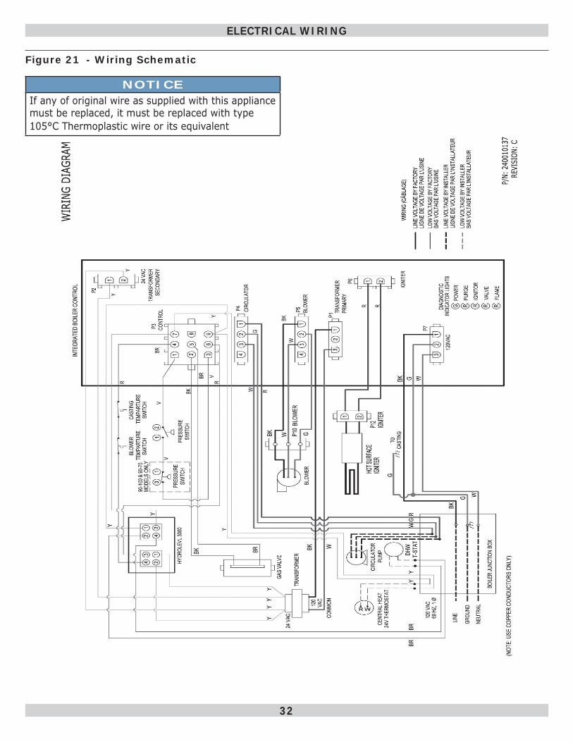
Figure 21 - Wiring Schematic
NOTICEIf any of original wire as supplied with this appliance must be replaced, it must be replaced with type105°C Thermoplastic wire or its equivalent
33
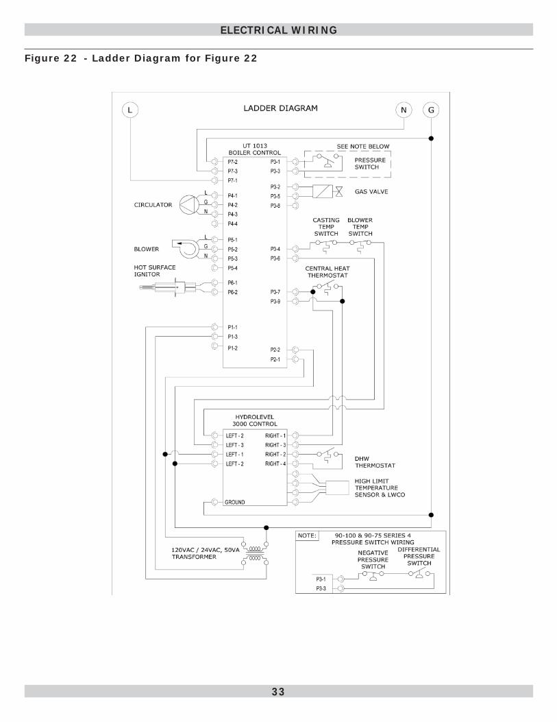
Figure 22 - Ladder Diagram for Figure 22
ELECTRICAL WIRING
34
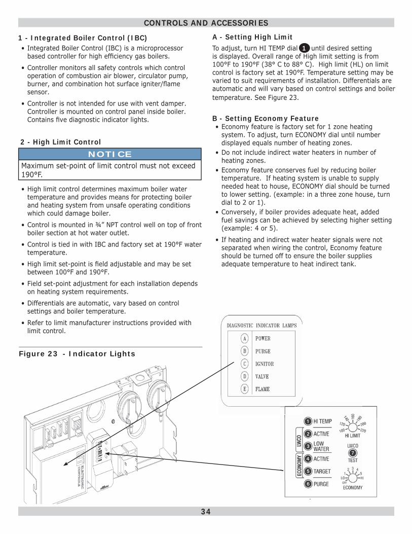
1 - Integrated Boiler Control (IBC)• Integrated Boiler Control (IBC) is a microprocessor
based controller for high effi ciency gas boilers.
• Controller monitors all safety controls which control operation of combustion air blower, circulator pump, burner, and combination hot surface igniter/fl ame sensor.
• Controller is not intended for use with vent damper. Controller is mounted on control panel inside boiler. Contains fi ve diagnostic indicator lights.
2 - High Limit ControlNOTICE
Maximum set-point of limit control must not exceed 190°F.
• High limit control determines maximum boiler water temperature and provides means for protecting boiler and heating system from unsafe operating conditions which could damage boiler.
• Control is mounted in ¾” NPT control well on top of front boiler section at hot water outlet.
• Control is tied in with IBC and factory set at 190°F water temperature.
• High limit set-point is fi eld adjustable and may be set between 100°F and 190°F.
• Field set-point adjustment for each installation depends on heating system requirements.
• Differentials are automatic, vary based on control settings and boiler temperature.
• Refer to limit manufacturer instructions provided with limit control.
CONTROLS AND ACCESSORIES
Figure 23 - Indicator Lights
A - Setting High LimitTo adjust, turn HI TEMP dial 1 until desired setting is displayed. Overall range of High limit setting is from 100°F to 190°F (38° C to 88° C). High limit (HL) on limit control is factory set at 190°F. Temperature setting may be varied to suit requirements of installation. Differentials are automatic and will vary based on control settings and boiler temperature. See Figure 23.
B - Setting Economy Feature • Economy feature is factory set for 1 zone heating
system. To adjust, turn ECONOMY dial until number displayed equals number of heating zones.
• Do not include indirect water heaters in number of heating zones.
• Economy feature conserves fuel by reducing boiler temperature. If heating system is unable to supply needed heat to house, ECONOMY dial should be turned to lower setting. (example: in a three zone house, turn dial to 2 or 1).
• Conversely, if boiler provides adequate heat, added fuel savings can be achieved by selecting higher setting (example: 4 or 5).
• If heating and indirect water heater signals were not separated when wiring the control, Economy feature should be turned off to ensure the boiler supplies adequate temperature to heat indirect tank.
35
SETTING
OFFDisables economy function. Will allow boiler to fi re until hi-limit temp is reached and re-fi re with a 10° subtractive differential.
LOProvides lowest level of fuel savings. Use this set-ting only if the house does not stay warm at higher settings.
1 Recommended setting for single zone systems.2 Recommended setting for Two zone systems.3 Recommended setting for Three zone systems.4 Recommended setting for Four zone systems.5 Recommended setting for Five zone systems.HI Provides highest level of fuel savings.
C - DifferentialsDifferentials are automatic and will vary based on the control settings and boiler temperature.
3 - Gas Control ValveElectrically controlled Combination Gas Control Valve is designed to meet requirements for use with hot surface ignition found in this boiler. Valve is piped to gas/air mixer.
4 - Hot Surface IgniterIgniter is mounted next to burner through gas/air mixer. The igniter also serves as means for proving main burner fl ame by fl ame rectifi cation. In the event of a lack of fl ame signal on three (3) consecutive trials for ignition, IBC will fl ash the VALVE light when locked out due to failed ignition.
5 - Draft Inducer Temperature Safety SwitchDraft Inducer Temperature Safety Switch is a disc thermostat (180°F setpoint) located on induced draft fan outlet port. Switch protects inducer and vent pipe from potential high temperature condition for discharging fl ue gases. Condition would typically be result of higher high limit control setting or over fi ring. Temperature safety switch automatically resets when the vent temperature decreases. (15°F switch differential).
6 - Casting Temperature Safety SwitchIn event of lack of or loss of water in boiler, Casting Temperature Safety Switch (300 °F setpoint) installed on top of the aluminum boiler section shuts off boiler by shutting off power to Integrated Boiler Control (IBC). This fault requires manual reset of casting temperature safety switch to restart the boiler. Verify that boiler is properly fi lled with water before resetting this switch. Never run cold water into a hot empty boiler.
CONTROLS AND ACCESSORIES
7 - Differential Pressure Air Proving Switch/Blocked Vent Safety ShutoffDifferential pressure switch monitors air fl ow by sensing differential pressure measured in inches of water (” w.c.). Pressure switch contacts close when draft inducer is running. Closed switch indicates there is adequate air fl ow for combustion. Pressure switch shuts off main burner if differential pressure is inadequate due to blocked vent pipe, blocked air intake, blocked boiler sections, or blocked draft inducer. If pressure switch does not close within 5 minutes of blower being turned on, control locks out with PURGE light fl ashing to indicate pressure switch fault.
8 - Draft InducerDraft inducer (blower) provides means for pulling combustion air into and through the mixer, burner, fl ue ways of cast aluminum boiler sections and fl ue adapter before being discharged through vent piping to outdoors. See applicable sections for proper sizing and installation of combustion air and vent piping in this manual.
9 - Circulator Pump (Optional)Every forced hot water system requires at least one circulating pump. Circulating pump imparts the necessary energy to move water through closed loop supply and return piping systems, terminal heating equipment (i.e. fi nned tube radiators, etc.) and back through boiler for reheating.To provide required hot water fl ow rates, circulator pump must be properly sized to overcome frictional losses (usually measured in feet of water, also referred to as “pump head loss”) of supply and return piping systems and boiler. The circulator pump is furnished for single zone or zone valve controlled heating system and should be located on downstream (i.e., pumping away) side of expansion tank. For pump controlled system (where there is a circulator for each zone) circulator provided with boiler can work for one zone. For more details on piping and circulators, see “Near Boiler Piping” on page 11 .
10 - Drain ValveManual drain valve provides means of draining water in heating system, including boiler and hot water supply and return piping systems installed above drain valve. This drain valve is installed in ¾” tapping at bottom of front boiler section. Any piping installed below elevation of this drain valve will require additional drain valves to be installed at low points in piping systems in order to drain entire system.
36
Water Quality, Water Treatment and Freeze Protection - see Appendix A
Filling Boiler With Water And Purging Air For Systems With Diaphragm Type Expansion TanksRefer to the appropriate diagrams, “Near Boiler Piping” on page 11 for more information.1. Close all zone service valves on the supply and return
piping. Open the feed valve and fi ll boiler with water. Make sure air vent is open. Hold relief valve open until water runs air free for fi ve seconds to rapidly bleed air from boiler, then let the relief valve snap shut.
2. Open the zone service valve on the supply pipe for the fi rst zone. Open the purge valve on the fi rst zone. Feed water will fi ll the zone, pushing air out the purge valve. Close the purge valve when the water runs air free. Close the zone service valve.
3. Repeat step 2 for all remaining zones.4. Open all service valves. Any air remaining trapped in
the return lines between the service valves and the boiler will be pushed towards the air vent when the boiler is placed in operation.
5. Inspect piping system. Repair any leaks immediately.
Purging Air For Systems With Conventional Closed Type Expansion Tanks:Refer to the appropriate diagrams “Near Boiler Piping” on page 11 for more information.1. Close all zone service valves on the supply and return
piping and close the expansion tank service valve. Drain expansion tank. Open the feed valve and fi ll boiler with water. Hold relief valve open until water runs air free for fi ve seconds to rapidly bleed air from boiler, then let the relief valve snap shut.
2. Open the zone service valve on the supply pipe for the fi rst zone. Open the purge valve on the fi rst zone. Feed water will fi ll the zone, pushing air out the purge valve. Close the purge valve when the water runs air free. Close the zone service valve.
3. Repeat step 2 for all remaining zones.4. Open the expansion tank service valve and the tank
vent. Fill the tank to the proper level and close the tank vent. Remove the handle from the expansion tank service valve so the homeowner doesn’t accidentally close it.
5. Open all service valves. Any air remaining trapped in the return lines between the service valves and the boiler will be pushed towards the expansion tank when the boiler is placed in operation.
6. Inspect piping system. Repair any leaks immediately.
Control - System StartupAt initial start up, with the Economy feature active, the control establishes a 145°F target temperature. To test the high limit shut-off function, the Economy dial must be turned to OFF. Once tested, restore the Economy setting. If the heating demand is high, the target will increase over time to satisfy the heat load.
How Thermal Targeting WorksThermal targeting technology analyzes thermostat activity and continually evaluates how much heat the house requires.When it is very cold outside, heat demand is high and limit control will raise boilers target temperature to provide heat.When outside temperature is mild, heat demand is low. Limit control will lower boiler’s target temperature saving fuel.
START UP
37
Stop! Read Safety information above.1. Set thermostat to lowest setting.2. Turn off all electric power to the appliance.3. This appliance is equipped with an ignition device which
automatically lights the burner. DO NOT try to light the burner by hand.
4. Remove the front jacket panel.5. Turn the gas control knob clockwise to “OFF”.6. Wait fi ve (5) minutes to clear out any gas. Then smell
for gas, including near the fl oor. If you smell gas, STOP! Follow “B” in the safety information above on this label. If you don’t smell gas go on to next step.
7. Turn the gas control knob counterclockwise to “ON”.
8. Replace front jacket panel.9. Turn on all electrical power to the appliance.10. Set the thermostat to desired setting.11. If the appliance will not operate, follow the instructions
“To Turn Off Gas To Appliance” and call your service technician or gas supplier.
To Turn Off Gas To Appliance1. Set the thermostat to lowest setting.2. Turn off all electric power to the appliance if service is
to be preformed.3. Remove the front jacket panel.4. Turn gas control knob clockwise to “OFF”.5. Replace the front jacket panel.
OPERATING INSTRUCTIONS
WARNINGIf you do not follow these instructions exactly, a fi re or explosion may result causing property damage, personal injury or loss of life.• This appliance is equipped with an ignition device
which automatically lights burner. Do NOT try to light this burner by hand.
• Before operating smell all around appliance area for gas. Be sure to smell next to fl oor because some gas is heavier than air and will settle to the fl oor.
• Use only your hand to turn the gas shutoff valve. Never use tools. If valve will not turn by hand, do not try to repair it, call a qualifi ed service technician. Force or attempted repair may result in fi re or explosion.
• Do not use this appliance if any part has been under water. Immediately call a qualifi ed service technician to inspect appliance and to replace any part of control system and any gas control which has been under water.
!
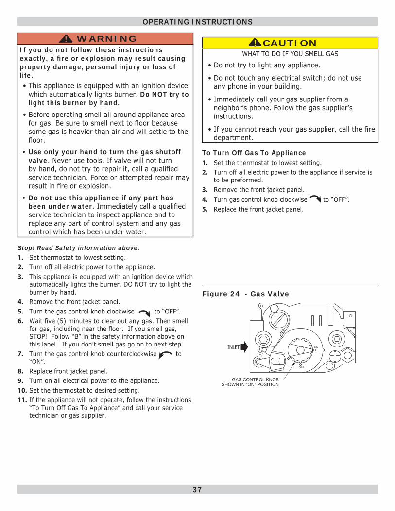
OFF
ONINLET
GAS CONTROL KNOB
SHOWN IN "ON" POSITION
Figure 24 - Gas Valve
CAUTIONWHAT TO DO IF YOU SMELL GAS
• Do not try to light any appliance.
• Do not touch any electrical switch; do not use any phone in your building.
• Immediately call your gas supplier from a neighbor’s phone. Follow the gas supplier’s instructions.
• If you cannot reach your gas supplier, call the fi re department.
!!
38
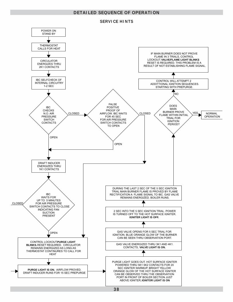
DETAILED SEQUENCE OF OPERATION
SERVICE HINTS
POWER ON STAND BY
THERMOSTATCALLS FOR HEAT
CIRCULATORENERGIZES THRU
2K1 CONTACTS
IBC SELFCHECK OF INTERNAL CIRCUITRY
1-2 SEC
IBC CHECKS N.O. AIR
PRESSURESWITCH
CONTACTS
FALSE POSITIVE
PROOF OF AIRFLOW. IBC WAITS
FOR 45 SEC FOR AIR PRESSURE SWITCH CONTACTS
TO OPEN
CLOSED CLOSED
DRAFT INDUCERENERGIZES THRU
1K1 CONTACTS
OPEN
IBC WAITS FOR
UP TO 5 MINUTES FOR AIR PRESSURE
SWITCH CONTACTS TO CLOSEINDICATING FAN
SUCTION PRESENT
CLOSED
CONTROL LOCKOUT. PURGE LIGHT BLINKS. RESET REQUIRED. CIRCULATOR
REMAINS ENERGIZED AS LONG AS THERMOSTAT CONTINURES TO CALL FOR
HEAT
OPEN
PURGE LIGHT IS ON. AIRFLOW PROVED.DRAFT INDUCER RUNS FOR 15 SEC PREPURGE
OPEN
PURGE LIGHT GOES OUT. HOT SURFACE IGNITER POWERED THRU 5K1 5K2 CONTACTS FOR 20
SEC IGNITER WARMUP. BRIGHT YELLOW ORANGE GLOW OF THE HOT SURFACE IGNITER CAN BE OBSERVED THRU THE OBSERVATION
PORT IN FRONT OF BOILER SECTION JUST ABOVE IGNITER, IGNITOR LIGHT IS ON
GAS VALVE ENERGIZED THRU 3K1 AND 4K1.CONTACTS, VALVE LIGHT IS ON.
GAS VALVE OPENS FOR 5 SEC TRIAL FOR IGNITION. BLUE ORANGE GLOW OF THE BURNER
CAN BE SEEN THRU OBSERVATION PORT.
2 SEC INTO THE 5 SEC IGNITION TRIAL. POWER IS TURNED OFF TO THE HOT SURFACE IGNITER.
IGNITER LIGHT IS OFF.
DURING THE LAST 2 SEC OF THE 5 SEC IGNITION TRIAL MAIN BURNER FLAME IS PROVED BY FLAME
RECTIFICATION A FLAME SIGNAL TO IBC. GAS VALVE REMAINS ENERGIZED. BOILER RUNS.
DOES MAIN
BURNER PROVE FLAME WITHIN INITIAL
TRIAL FOR IGNITION PERIOD?
CONTROL WILL ATTEMPT 2 ADDITTIONAL IGNITION SEQUENCES.
STARTING WITH PREPURGE.
IF MAIN BURNER DOES NOT PROVE FLAME IN 3 TRIALS, CONTROL
LOCKOUT. VALVE/FLAME LIGHT BLINKS, RESET IS REQUIRED. THIS PROBLEM IS A
RESULT OF NOT ESTABLISHING FLAME SIGNAL.
NORMAL OPERATION
YES
NO
39
DETAILED SEQUENCE OF OPERATION
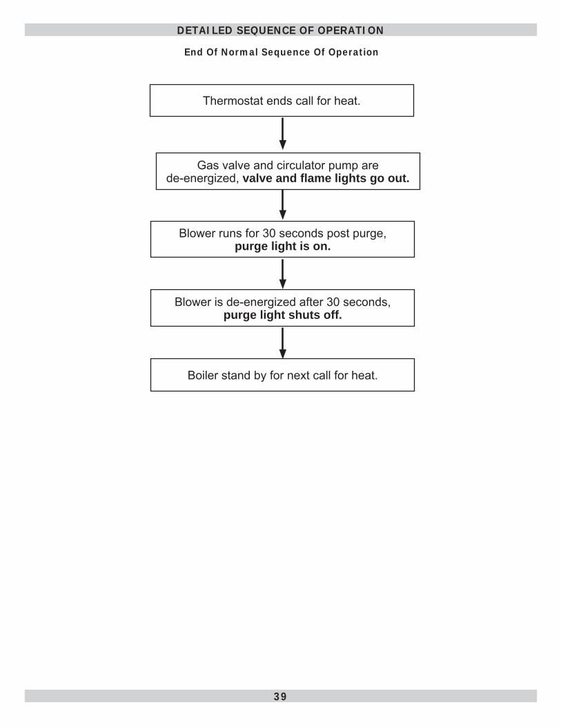
End Of Normal Sequence Of Operation
Thermostat ends call for heat.
Gas valve and circulator pump are de-energized, valve and fl ame lights go out.
Blower runs for 30 seconds post purge, purge light is on.
Blower is de-energized after 30 seconds, purge light shuts off.
Boiler stand by for next call for heat.
40
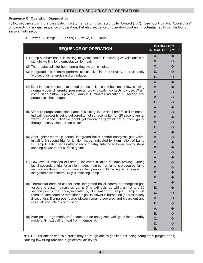
Sequence Of Operation DiagnosticsFollow sequence using the diagnostic indicator lamps on Integrated Boiler Control (IBC). See “Controls And Accessories” on page 34 for normal sequence of operation. Detailed sequence of operation containing potential faults can be found in service hints section.
SEQUENCE OF OPERATION DIAGNOSTIC INDICATOR LAMPS
(1) Lamp A is illuminated, indicating integrated control is receiving 24 volts and is in standby waiting for thermostat call for heat.
(2) Thermostat calls for heat, energizing system circulator.(3) Integrated boiler control performs self check of internal circuitry, approximately
two seconds, energizing draft inducer.
A.
B.
C.
D.
E.
(4) Draft inducer comes up to speed and establishes combustion airfl ow, causing normally open differential pressure air proving switch contacts to close. When combustion airfl ow is proved, Lamp B illuminates indicating 15 second pre-purge cycle has begun.
A.
B.
C.
D.
E.
(5) After pre-purge completion, Lamp B is extinguished and Lamp C is illuminated, indicating power is being delivered to hot surface igniter for 20 second igniter warm-up period. Observe bright yellow-orange glow of hot surface igniter through observation port on boiler.
A.
B.
C.
D.
E.
(6) After igniter warm-up period, integrated boiler control energizes gas valve, initiating 6 second trial for ignition mode, indicated by illumination of Lamp D. Lamp C extinguishes after 2 second delay. Integrated boiler control stops sending power to hot surface igniter.
A.
B.
C.
D.
E.
(7) Low level illumination of Lamp E indicates initiation of fl ame proving. During last 2 seconds of trial for ignition mode, main burner fl ame is proven by fl ame rectifi cation through hot surface igniter, providing fl ame signal is relayed to integrated boiler control, fully illuminating Lamp E.
A.
B.
C.
D.
E.
(8) Thermostat ends its call for heat. Integrated boiler control de-energizes gas valve and system circulator. Lamp D is extinguished while unit enters 30 second post purge mode, indicated by illumination of Lamp B. Lamp E will remains illuminated as remainder of gas in blower is burned off (approximately 2 seconds). During post purge blower remains powered and clears out any residual products of combustion.
A.
B.
C.
D.
E.
(9) After post purge mode draft inducer is de-energized. Unit goes into standby mode until next call for heat from thermostat.
A.
B.
C.
D.
E.
NOTE: First one or two cold starts may be rough due to gas line not being completely purged of air, causing low fi ring rate and high excess air levels.
A - Power, B - Purge, C - Igniter, D - Valve, E - Flame
DETAILED SEQUENCE OF OPERATION
41
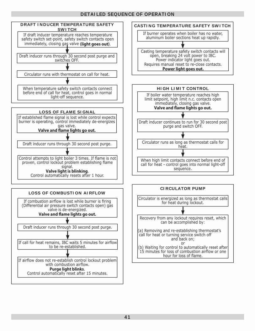
DRAFT INDUCER TEMPERATURE SAFETY SWITCH
Draft inducer runs through 30 second post purge and switches OFF.
Circulator runs with thermostat on call for heat.
When temperature safety switch contacts connect before end of call for heat, control goes in normal
light-off sequence.
LOSS OF COMBUSTION AIRFLOW
If combustion airfl ow is lost while burner is fi ring (Differential air pressure switch contacts open) gas
valve is de-energized. Valve and fl ame lights go out.
Draft inducer runs through 30 second post purge.
If call for heat remains, IBC waits 5 minutes for airfl ow to be re-established.
If airfl ow does not re-establish control lockout problem with combustion airfl ow.
Purge light blinks. Control automatically reset after 15 minutes.
LOSS OF FLAME SIGNALIf established fl ame signal is lost while control expects burner is operating, control immediately de-energizes
gas valve. Valve and fl ame lights go out.
Draft inducer runs through 30 second post purge.
Control attempts to light boiler 3 times. If fl ame is not proven, control lockout problem establishing fl ame
signal. Valve light is blinking.
Control automatically resets after 1 hour.
HIGH LIMIT CONTROLIf boiler water temperature reaches high
limit setpoint, high limit n.c. contacts open immediately, closing gas valve.
Valve and fl ame lights go out.
Draft inducer continues to run for 30 second post purge and switch OFF.
Circulator runs as long as thermostat calls for heat.
When high limit contacts connect before end of call for heat - control goes into normal light-off
sequence.
CASTING TEMPERATURE SAFETY SWITCH
If burner operates when boiler has no water, aluminum boiler sections heat up rapidly.
Casting temperature safety switch contacts will open, breaking 24 volt power to IBC.
Power indicator light goes out. Requires manual reset to re-close contacts.
Power light goes out.
CIRCULATOR PUMP
Circulator is energized as long as thermostat calls for heat during lockout.
Recovery from any lockout requires reset, which can be accomplished by:
(a) Removing and re-establishing thermostat’s call for heat or turning service switch off
and back on; or
(b) Waiting for control to automatically reset after 15 minutes for loss of combustion airfl ow or one
hour for loss of fl ame.
If draft inducer temperature reaches temperature safety switch set-point, safety switch contacts open
immediately, closing gas valve (light goes out).
DETAILED SEQUENCE OF OPERATION
42
First couple of cold starts may be rough due to gas line not being completely purged of air, causing low fi ring rate and high excess air levels.
Inspect Venting And Air Intake SystemOperate boiler and verify all vent/air intake connections are gas-tight and watertight. Repair any leaks immediately.
Inspect Condensate DrainVerify all connections are watertight, and that condensate fl ows freely. Repair any leaks immediately.
Inspect System PipingVerify all connections are watertight. Repair any leaks immediately.
VERIFICATION PROCEDURE AND ADJUSTMENT
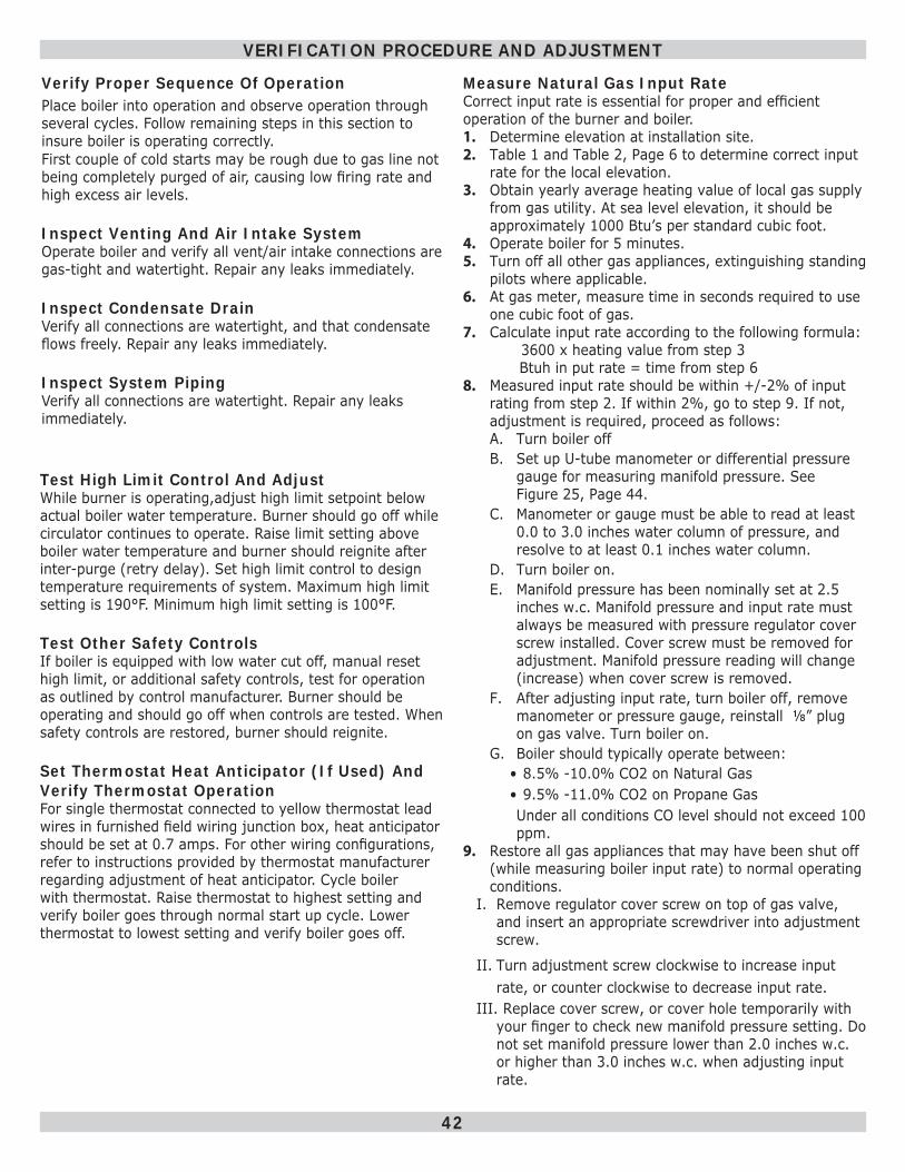
Verify Proper Sequence Of OperationPlace boiler into operation and observe operation through several cycles. Follow remaining steps in this section to insure boiler is operating correctly.
Test High Limit Control And AdjustWhile burner is operating,adjust high limit setpoint below actual boiler water temperature. Burner should go off while circulator continues to operate. Raise limit setting above boiler water temperature and burner should reignite after inter-purge (retry delay). Set high limit control to design temperature requirements of system. Maximum high limit setting is 190°F. Minimum high limit setting is 100°F.
Test Other Safety ControlsIf boiler is equipped with low water cut off, manual reset high limit, or additional safety controls, test for operation as outlined by control manufacturer. Burner should be operating and should go off when controls are tested. When safety controls are restored, burner should reignite.
Set Thermostat Heat Anticipator (If Used) And Verify Thermostat OperationFor single thermostat connected to yellow thermostat lead wires in furnished fi eld wiring junction box, heat anticipator should be set at 0.7 amps. For other wiring confi gurations, refer to instructions provided by thermostat manufacturer regarding adjustment of heat anticipator. Cycle boiler with thermostat. Raise thermostat to highest setting and verify boiler goes through normal start up cycle. Lower thermostat to lowest setting and verify boiler goes off.
Measure Natural Gas Input RateCorrect input rate is essential for proper and effi cient operation of the burner and boiler. 1. Determine elevation at installation site.2. Table 1 and Table 2, Page 6 to determine correct input
rate for the local elevation.3. Obtain yearly average heating value of local gas supply
from gas utility. At sea level elevation, it should be approximately 1000 Btu’s per standard cubic foot.
4. Operate boiler for 5 minutes.5. Turn off all other gas appliances, extinguishing standing
pilots where applicable.6. At gas meter, measure time in seconds required to use
one cubic foot of gas.7. Calculate input rate according to the following formula: 3600 x heating value from step 3 Btuh in put rate = time from step 68. Measured input rate should be within +/-2% of input
rating from step 2. If within 2%, go to step 9. If not, adjustment is required, proceed as follows:A. Turn boiler offB. Set up U-tube manometer or differential pressure
gauge for measuring manifold pressure. See Figure 25, Page 44 .
C. Manometer or gauge must be able to read at least 0.0 to 3.0 inches water column of pressure, and resolve to at least 0.1 inches water column.
D. Turn boiler on.E. Manifold pressure has been nominally set at 2.5
inches w.c. Manifold pressure and input rate must always be measured with pressure regulator cover screw installed. Cover screw must be removed for adjustment. Manifold pressure reading will change (increase) when cover screw is removed.
F. After adjusting input rate, turn boiler off, remove manometer or pressure gauge, reinstall ⅛” plug on gas valve. Turn boiler on.
G. Boiler should typically operate between:• 8.5% -10.0% CO2 on Natural Gas• 9.5% -11.0% CO2 on Propane GasUnder all conditions CO level should not exceed 100 ppm.
9. Restore all gas appliances that may have been shut off (while measuring boiler input rate) to normal operating conditions.
I. Remove regulator cover screw on top of gas valve, and insert an appropriate screwdriver into adjustment screw.
II. Turn adjustment screw clockwise to increase input rate, or counter clockwise to decrease input rate.
III. Replace cover screw, or cover hole temporarily with your fi nger to check new manifold pressure setting. Do not set manifold pressure lower than 2.0 inches w.c. or higher than 3.0 inches w.c. when adjusting input rate.
43
VERIFICATION PROCEDURE AND ADJUSTMENT
IV. Measure new input rate (cover screw must be installed). Repeat steps I.-IV until the input rate is within +/-2% of the nameplate input rating.
V. If the actual input rate can not be set to within 2% of the correct input rating by adjusting manifold pressure, a change in gas orifi ce size is required. Consult the boiler manufacturer for information on correct orifi ce sizing. The specifi c gravity (G) and the higher heating value (HHV) of the local natural gas must be obtained from the local gas utility in order to determine the proper orifi ce size.
Set Thermostat To Desired Room TemperatureObserve several operating cycles to verify proper operation.
Review All InstructionsReview all instructions shipped with this boiler with owner or maintenance person. Instructions must be affi xed on or adjacent to the boiler.Complete and sign the “Installation and Check-Out Certifi cate” on page 62 .
44
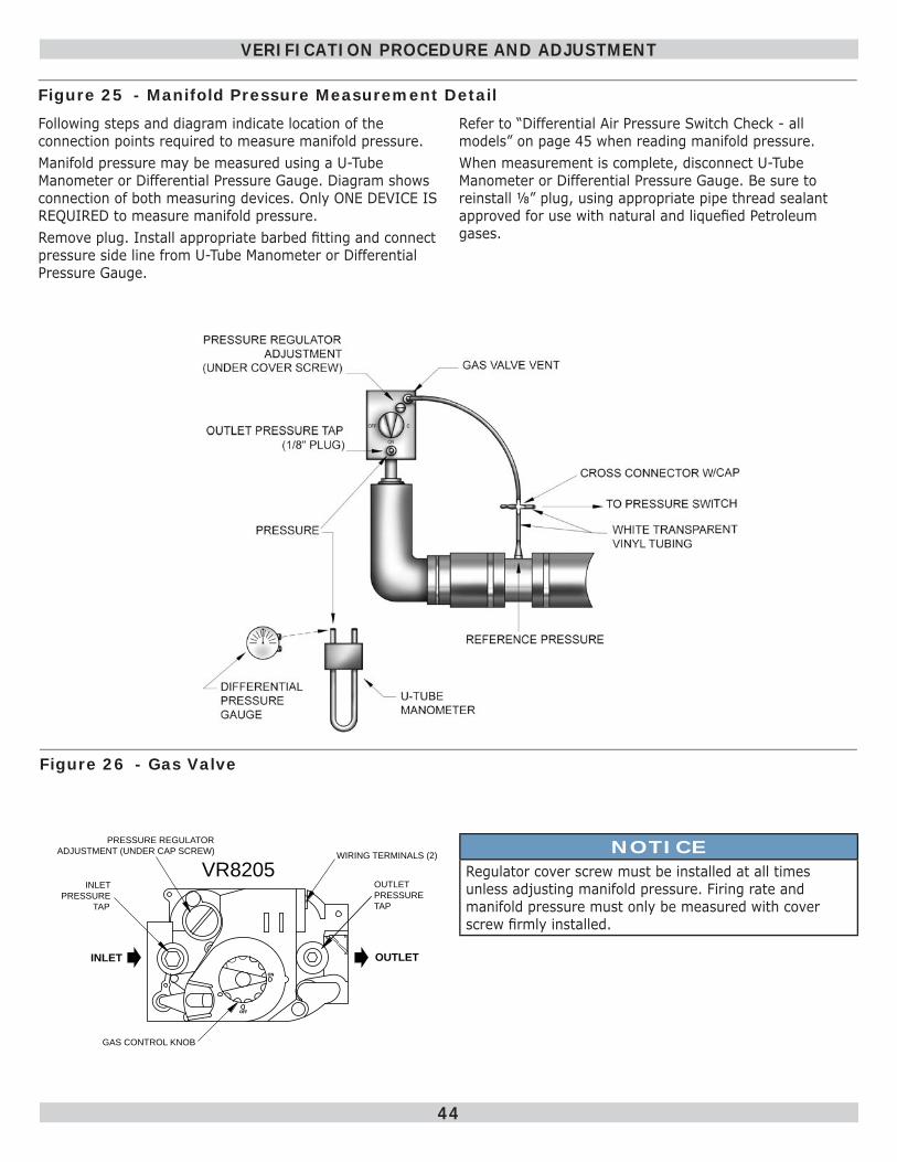
Following steps and diagram indicate location of the connection points required to measure manifold pressure.Manifold pressure may be measured using a U-Tube Manometer or Differential Pressure Gauge. Diagram shows connection of both measuring devices. Only ONE DEVICE IS REQUIRED to measure manifold pressure.Remove plug. Install appropriate barbed fi tting and connect pressure side line from U-Tube Manometer or Differential Pressure Gauge.
OFF
ON
INLET OUTLET
GAS CONTROL KNOB
PRESSURE REGULATOR
ADJUSTMENT (UNDER CAP SCREW)
INLET
PRESSURE
TAP
VR8205 WIRING TERMINALS (2)
OUTLET
PRESSURE
TAP
Figure 25 - Manifold Pressure Measurement Detail
Figure 26 - Gas Valve
VERIFICATION PROCEDURE AND ADJUSTMENT
Refer to “Differential Air Pressure Switch Check - all models” on page 45 when reading manifold pressure.When measurement is complete, disconnect U-Tube Manometer or Differential Pressure Gauge. Be sure to reinstall ⅛” plug, using appropriate pipe thread sealant approved for use with natural and liquefi ed Petroleum gases.
NOTICERegulator cover screw must be installed at all times unless adjusting manifold pressure. Firing rate and manifold pressure must only be measured with cover screw fi rmly installed.
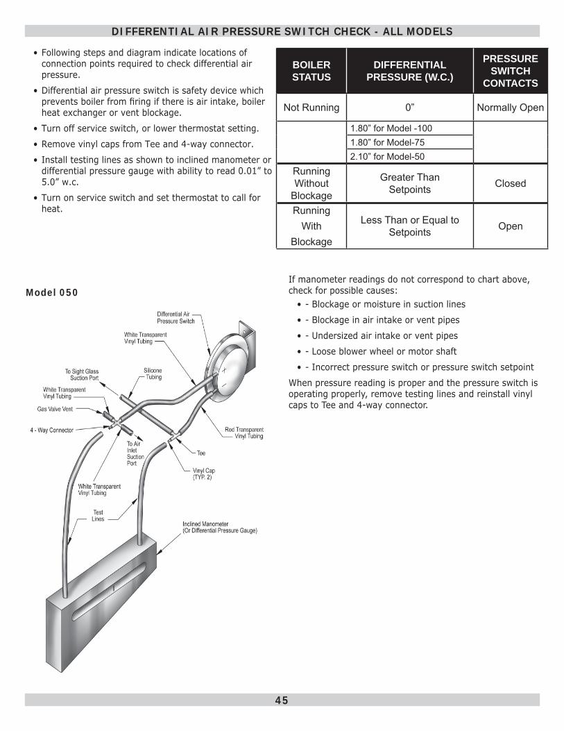
45
• Following steps and diagram indicate locations of connection points required to check differential air pressure.
• Differential air pressure switch is safety device which prevents boiler from fi ring if there is air intake, boiler heat exchanger or vent blockage.
• Turn off service switch, or lower thermostat setting.
• Remove vinyl caps from Tee and 4-way connector.
• Install testing lines as shown to inclined manometer or differential pressure gauge with ability to read 0.01” to 5.0” w.c.
• Turn on service switch and set thermostat to call for heat.
BOILER STATUS
DIFFERENTIAL PRESSURE (W.C.)
PRESSURE SWITCH
CONTACTS
Not Running 0” Normally Open
1.80” for Model -100 1.80” for Model-75 2.10” for Model-50
Running Without
Blockage
Greater Than Setpoints Closed
Running With
Blockage
Less Than or Equal to Setpoints Open
If manometer readings do not correspond to chart above, check for possible causes:
• - Blockage or moisture in suction lines
• - Blockage in air intake or vent pipes
• - Undersized air intake or vent pipes
• - Loose blower wheel or motor shaft
• - Incorrect pressure switch or pressure switch setpoint
When pressure reading is proper and the pressure switch is operating properly, remove testing lines and reinstall vinyl caps to Tee and 4-way connector.
DIFFERENTIAL AIR PRESSURE SWITCH CHECK - ALL MODELS
Model 050
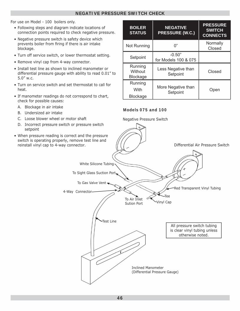
46
NEGATIVE PRESSURE SWITCH CHECK
BOILER STATUS
NEGATIVE PRESSURE (W.C.)
PRESSURE SWITCH
CONNECTS
Not Running 0” Normally Closed
Setpoint -0.50” for Models 100 & 075
Running Without
Blockage
Less Negative than Setpoint Closed
Running With
Blockage
More Negative than Setpoint Open
To Gas Valve VentGas Valve Vent
For use on Model - 100 boilers only.• Following steps and diagram indicate locations of
connection points required to check negative pressure.
• Negative pressure switch is safety device which prevents boiler from fi ring if there is air intake blockage.
• Turn off service switch, or lower thermostat setting.
• Remove vinyl cap from 4-way connector.
• Install test line as shown to inclined manometer or differential pressure gauge with ability to read 0.01” to 5.0” w.c.
• Turn on service switch and set thermostat to call for heat.
• If manometer readings do not correspond to chart, check for possible causes:A. Blockage in air intakeB. Undersized air intake C. Loose blower wheel or motor shaftD. Incorrect pressure switch or pressure switch
setpoint• When pressure reading is correct and the pressure
switch is operating properly, remove test line and reinstall vinyl cap to 4-way connector.
Negative Pressure Switch
Differential Air Pressure Switch
Red Transparent Vinyl Tubing
Tee Vinyl Cap
All pressure switch tubing is clear vinyl tubing unless
otherwise noted.
Inclined Manometer (Differential Pressure Gauge)
Test Line
To Air Inlet Sution Port
To Sight Glass Suction Port
White Silicone Tubing
4-Way Connector
Models 075 and 100
47
Maintenance As Outlined Below Can Be Performed By Owner Unless Otherwise Noted.
• The acidic nature of fl ue gasses condensing on aluminum boiler sections may cause formation of aluminum oxide. This oxide formation is normal, is generally uniform throughout boiler sections, and represents negligible mass of aluminum that is consumed by oxidation during life of the boiler.
• If left unchecked, this buildup may eventually cause blockage of fl ue gas passages in boiler sections, reducing effi ciency, and ultimately shutting down the boiler due to lack of combustion air fl ow.
• Regular service and maintenance by a qualifi ed service agency must be performed to assure safe trouble free operation and maximum effi ciency.
Beginning Of Each Heating Season1. Annual service call by qualifi ed service agency, which
includes:A. Examine fl ue passages between boiler sections,
burner, and condensate lines, and clean if necessary following “Annual Examination And Cleaning Of Boiler Components” on page 48 .
B. Visually inspect venting and air intake system for proper function, deterioration or leakage. If vent or air intake show any signs of deterioration or leakage, repair or replace them, immediately. Insure proper reassembly and resealing of vent and air intake system
C. Check for and remove any obstruction to fl ow of combustion air or venting of fl ue gases. Check air baffl e located inside 1½” x 2” fl exible coupling on mixer, clean if necessary and make sure to put it back. Refer to repair parts diagram of mixer and pressure switch assembly for exact location.
D. Follow instructions for “Operating Instructions” on page 37 .
E. Follow instructions for “verifi cation Procedure and Adjustment” on page 42 .
F. Visually inspect condensate drain lines for proper operation and deterioration. Check for plugged condensate drain lines.
G. Check silicone rubber seals between boiler sections. Insure that there are no leaks. Use RTV silicone rubber adhesive sealant rated for at least 400° F to replace or repair seals in locations where original seals have deteriorated.
H. Check all gasketed joints for leakage, and tighten bolts or replace gaskets if necessary.
I. Remove jacket front and top panels and check for piping leaks around relief valve and other fi ttings. Repair, if found. DO NOT use stop leak compounds.
J. Check igniter for cracks and deterioration. Replace if necessary.
K. Check for water in pressure switch tubing. Drain if necessary.
2. Check boiler area is free from combustible materials, gasoline, and other fl ammable vapors and liquids.
3. Circulator pump and blower motor furnished with boiler are permanently lubricated from factory and require no further lubrication. Additional or non-factory supplied pumps and/or motors should be lubricated according to the pump and/or motor manufacturer’s instruction.
Daily During Heating Season1. Check for and remove any obstruction to the fl ow of
combustion air or venting of fl ue gases.2. Check boiler area is free from combustible materials,
gasoline, and other fl ammable vapors and liquids.
MAINTENANCE AND CLEANING
Monthly During Heating Season1. Remove jacket front and top panels and check for
piping leaks around relief valve and other fi ttings. If found, contact qualifi ed service agency to repair. DO NOT use stop leak compounds.
2. Test relief valve. Refer to valve manufacturers instructions packaged with relief valve.
3. Visually inspect venting and air intake system for proper function, deterioration, or leakage. If vent or air intake show any signs of deterioration or leakage, contact a qualifi ed service agency to repair or replace immediately and to insure proper reassembly and resealing of vent and air intake system.
4. Visually inspect clear vinyl condensate lines and PVC condensate drain pipe for proper operation, leakage, and deterioration. If condensate lines or drain pipe show any signs of blockage, leakage, or deterioration contact a qualifi ed service agency to clean, repair, or replace them immediately.
Periodically During Heating SeasonWhere low water cutoffs are used, periodic inspection of low water cut off is necessary, including fl ushing of fl oat type devices. Refer to low water cut off manufacturer’s specifi c instructions.
End of Each Heating Season - Annual Shutdown ProcedureFollow instructions “To Turn Off Gas To Appliance” on page 37 .If heating system is to remain out of service during freezing weather, and does not contain antifreeze, drain system completely. If boiler will be exposed to freezing temperatures, drain condensate lines. Otherwise, do not drain system or boiler.
48
K. Reinstall burner and mixer gasket and position mixer assembly over studs. Install fi ve (5) nuts but do not tighten. Reinstall igniter and igniter gasket and fasten with two (2) screws. Use care when installing the igniter. Tighten fi ve (5) nuts holding mixer assembly.
L. Connect:• Gas line to gas valve• Condensate drain line to boiler • Pressure switch hose to gas valve• Air by-pass to mixer• 1 ½” x 2” fl exible coupling to air inlet and make
sure to put air baffl e back to correct position• Igniter wires • Gas valve wires
3. Visually inspect condensate lines leading from boiler sections and vent pipe connector to condensate trap. Refer to repair parts diagrams. Any foreign material or debris visible in condensate lines needs to be cleaned out as follows: A. Disconnect condensate drain lines from condensate
trap.B. Remove condensate trap and drain all water from
trap.C. Disconnect condensate lines from fi tting on bottom
of boiler and vent pipe connector.D. Run cold water through condensate lines and trap
to thoroughly fl ush out any sediment or debris.E. Reinstall condensate trap and condensate lines.F. Follow instructions under “Near Boiler Piping” for fi lling condensate trap with water.
4. Inspection of fl ue connector requires following steps. Refer to repair parts diagram.A. Loosen the clamp on the draft inducer end of the
2” vent pipe connector that connects the vent to the draft inducer. Disconnect (unplug) wiring harness from draft inducer motor and draft inducer temperature safety switch. Remove four (4) bolts that attach draft inducer to fl ue connector.
B. Remove draft inducer and gasket from top of fl ue connector.
C. Inspect interior of fl ue connector. Any buildup of sediment or aluminum oxide on inside surface must be cleaned. Position draft inducer gasket and draft inducer and fasten with four (4) screws. Be sure to connect ground wire from draft inducer motor to one of four mounting screws.
D. Connect wiring harness leads to draft inducer motor and draft inducer temperature safety switch.
E. Connect vent pipe connector to draft inducer outlet.
MAINTENANCE AND CLEANING
Annual Examination And Cleaning Of Boiler Components
DANGERBefore servicing, turn off electrical power to boiler at service switch. Close manual gas valve to turn gas supply OFF to boiler. Failure to comply will result in death or serious injury.
!
NOTICEHave qualifi ed service agency perform the following service procedures. Boiler owner should not attempt these procedures.
1. Before Servicing, turn off electrical power to boiler at service switch. Close manual gas valve to turn off gas supply to boiler.
2. Cleaning Flue passages between boiler sections. A. Any buildup of sediment or aluminum oxide (white
powdery or fl aky substance) in fl ue passages must be cleaned as follows.
B. Remove jacket front and top panels. Disconnect condensate drain line from barbed fi tting on bottom of boiler. Keep open end of drain line above water level in condensate trap to prevent trap from draining. Disconnect pressure switch hose from barbed fi tting on gas valve. Disconnect 1½ x 2” fl exible coupling from air inlet. Disconnect air by-pass (½” transparent vinyl tube) from bottom of mixer.
C. Remove air baffl e from ½” x 2” fl exible coupling and clean air baffl e if necessary. Refer to repair parts diagram, mixer and pressure switch assembly.
D. Confi rm manual gas valve is closed and disconnect gas line to gas valve at union. Disconnect wires to gas valve and igniter.
E. Loosen but do not remove fi ve (5) nuts attaching mixer assembly to boiler. Remove two (2) igniter screws and remove igniter.
F. Remove fi ve (5) nuts and remove mixer assembly. Remove burner and mixer gasket.
G. Aluminum oxide deposits are water soluble and may be rinsed away with spraying or running water. Before rinsing, connect a ½” I.D. hose to barbed fi tting on bottom of boiler and run hose to bucket or drain.
H. After rinsing, remove any remaining loosened sediment using shop vacuum with snorkel attachment.
I. Inspect burner for any foreign matter in fl ame ports or inside burner. Any foreign matter should be removed by blowing with compressed air or vacuuming.
J. Inspect interior of mixer for any signs of sediment or aluminum oxide and clean if necessary.
NOTICEVerify proper operation after servicing.
49
Important1. In reset from lockout condition, all electrical meter
readings at the gas control valve (24 vac) must be taken within trial for ignition period.
2. If any component does not function properly, make sure it is correctly installed and wired before replacing it.
3. Static electricity discharge can damage integrated boiler control (IBC). Touch metal surface to discharge static electricity before touching IBC.
4. IBC cannot be repaired. If it malfunctions it must be replaced.
5. Only trained service technicians should service IBC systems. Following troubleshooting, check out system following sequence of operation for a normal light off sequence.
6. All controls are factory tested in the assembly process and a defective control is generally the least likely cause. If you suspect you have a defective control, read through this section before you replace it.
7. It is extremely unlikely that the two consecutive controls are defective. If it seems to be happening, chances are that either there is nothing wrong with the control or it is being damaged by some other problem (an electrical short burning out a transformer, for example).
Initial Service Checks1. Before troubleshooting:
A. Make sure that circuit breaker is on or fuse is ok at electrical panel.
B. Make sure that service switch is on.C. Make sure that gas is on at the gas meter, at all
appropriate manual shutoff valves and at the gas control valve.
D. Make sure that the thermostat is calling for heat.E. Check that wire connectors at the integrated boiler
control and at the originating control are securely plugged in or connected.
F. Check that hoses are securely connected and are not plugged or damaged.
TROUBLESHOOTING
2. Troubleshooting tools:A. Voltmeter to check 120 vac and 24 vacB. Continuity tester.C. Inclined manometer or pressure gauge with
0-3.0” Range (0.01” Scale) for measuring suction pressures at pressure switch.
D. U-tube manometer or differential pressure gauge with 0-14” range (0.1” Scale) for measuring inlet and manifold gas pressures.
3. System Status:A. Consult “System Status” on pages 40 and 50.B. See Figure 23, Page 34, for location of boiler
Diagnostic Indicator Lamps.
WARNINGFire, explosion or shock hazard. Do not attempt to modify the physical or electrical characteristics of this boiler in any way. Failure to comply could result in death or serious injury.
!
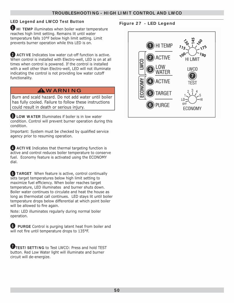
50
TROUBLESHOOTING - HIGH LIMIT CONTROL AND LWCO
LED Legend and LWCO Test Button1 HI TEMP illuminates when boiler water temperature
reaches high limit setting. Remains lit until water temperature falls 10°F below high limit setting. Limit prevents burner operation while this LED is on.
2 ACTIVE Indicates low water cut-off function is active. When control is installed with Electro-well, LED is on at all times when control is powered. If the control is installed with a well other than Electro-well, LED will not illuminate indicating the control is not providing low water cutoff functionality.
WARNINGBurn and scald hazard. Do not add water until boiler has fully cooled. Failure to follow these instructions could result in death or serious injury.
!
3 LOW WATER Illuminates if boiler is in low water condition. Control will prevent burner operation during this condition. Important: System must be checked by qualifi ed service agency prior to resuming operation.
4 ACTIVE Indicates that thermal targeting function is active and control reduces boiler temperature to conserve fuel. Economy feature is activated using the ECONOMY dial.
5 TARGET When feature is active, control continually
sets target temperatures below high limit setting to maximize fuel effi ciency. When boiler reaches target temperature, LED illuminates and burner shuts down. Boiler water continues to circulate and heat the house as long as thermostat call continues. LED stays lit until boiler temperature drops below differential at which point boiler will be allowed to fi re again. Note: LED illuminates regularly during normal boiler operation.
6 PURGE Control is purging latent heat from boiler and
will not fi re until temperature drops to 135°F.
7 TEST/SETTING to Test LWCO: Press and hold TEST button. Red Low Water light will illuminate and burner circuit will de-energize.
Figure 27 - LED Legend
115
100130 14
5160
175190
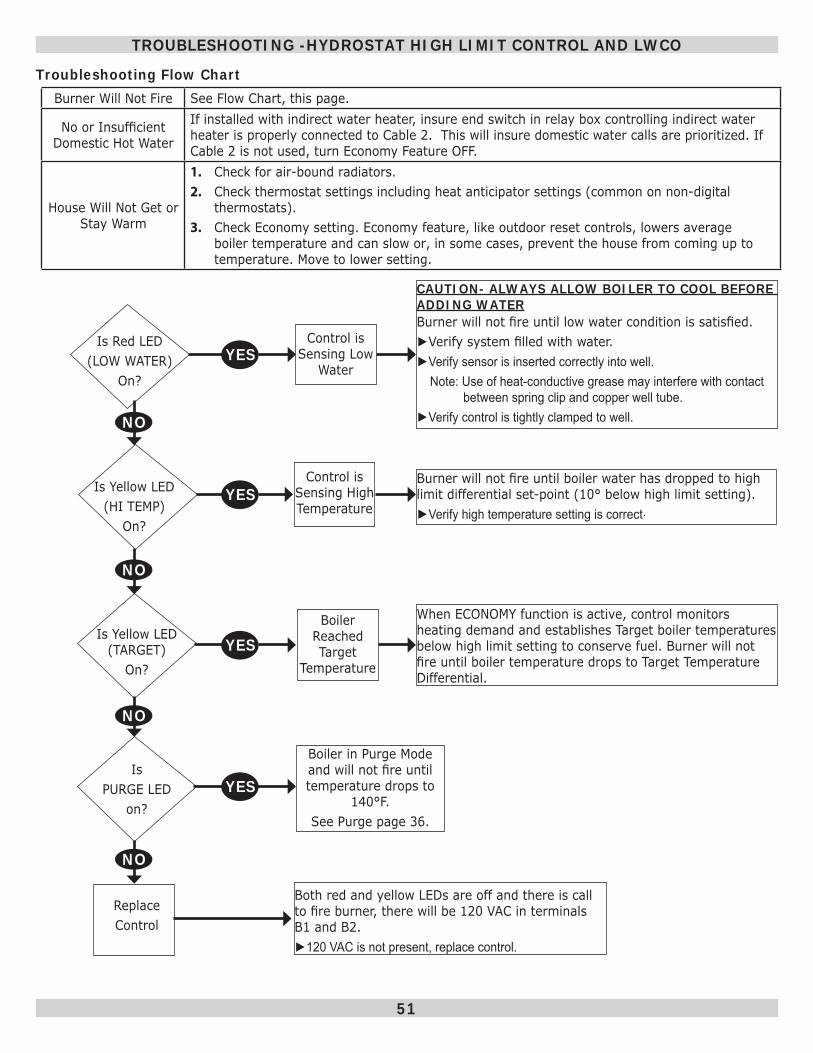
51
TROUBLESHOOTING -HYDROSTAT HIGH LIMIT CONTROL AND LWCO
Troubleshooting Flow ChartBurner Will Not Fire See Flow Chart, this page.
No or Insuffi cient Domestic Hot Water
If installed with indirect water heater, insure end switch in relay box controlling indirect water heater is properly connected to Cable 2. This will insure domestic water calls are prioritized. If Cable 2 is not used, turn Economy Feature OFF.
House Will Not Get or Stay Warm
1. Check for air-bound radiators.2. Check thermostat settings including heat anticipator settings (common on non-digital
thermostats). 3. Check Economy setting. Economy feature, like outdoor reset controls, lowers average
boiler temperature and can slow or, in some cases, prevent the house from coming up to temperature. Move to lower setting.
Is Red LED (LOW WATER)
On?
Is Yellow LED (HI TEMP)
On?
Is Yellow LED (TARGET)
On?
Is PURGE LED
on?
Replace Control
Control is Sensing Low
Water
Control is Sensing High Temperature
Boiler Reached Target
Temperature
Boiler in Purge Mode and will not fi re until temperature drops to
140°F. See Purge page 36.
Both red and yellow LEDs are off and there is call to fi re burner, there will be 120 VAC in terminals B1 and B2.►120 VAC is not present, replace control.
CAUTION- ALWAYS ALLOW BOILER TO COOL BEFORE ADDING WATERBurner will not fi re until low water condition is satisfi ed.►Verify system fi lled with water.►Verify sensor is inserted correctly into well. Note: Use of heat-conductive grease may interfere with contact between spring clip and copper well tube.►Verify control is tightly clamped to well.
Burner will not fi re until boiler water has dropped to high limit differential set-point (10° below high limit setting).►Verify high temperature setting is correct.
When ECONOMY function is active, control monitors heating demand and establishes Target boiler temperatures below high limit setting to conserve fuel. Burner will not fi re until boiler temperature drops to Target Temperature Differential.
YES
YES
YES
YES
NO
NO
NO
NO
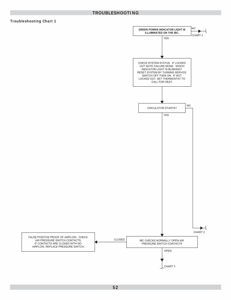
52
Troubleshooting Chart 1
TROUBLESHOOTING
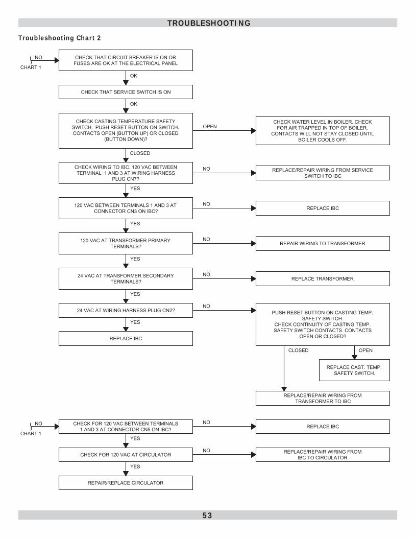
53
Troubleshooting Chart 2
TROUBLESHOOTING
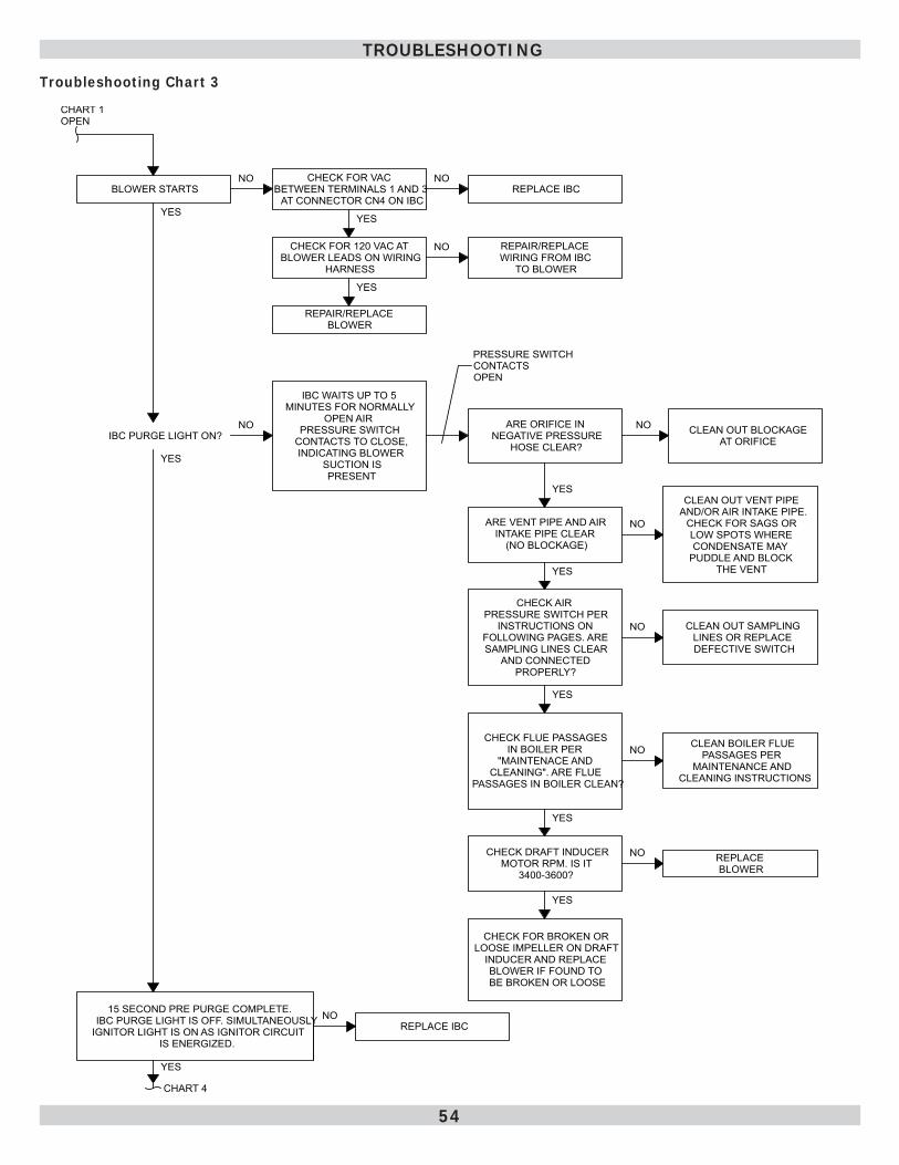
54
Troubleshooting Chart 3
CHECK FOR VAC BETWEEN TERMINALS 1 AND 3
AT CONNECTOR CN4 ON IBC
NO NOBLOWER STARTS REPLACE IBC
CHART 1OPEN
IBC PURGE LIGHT ON?NO
YES
IBC WAITS UP TO 5 MINUTES FOR NORMALLY
OPEN AIR PRESSURE SWITCH
CONTACTS TO CLOSE,INDICATING BLOWER
SUCTION IS PRESENT
YES
CHECK FOR 120 VAC AT BLOWER LEADS ON WIRING
HARNESS
YES
REPAIR/REPLACE BLOWER
NO REPAIR/REPLACE WIRING FROM IBC
TO BLOWER
PRESSURE SWITCH CONTACTS OPEN
ARE VENT PIPE AND AIR INTAKE PIPE CLEAR
(NO BLOCKAGE)
NO
CLEAN OUT VENT PIPE AND/OR AIR INTAKE PIPE.
CHECK FOR SAGS OR LOW SPOTS WHERE CONDENSATE MAY
PUDDLE AND BLOCK THE VENTYES
CHECK AIR PRESSURE SWITCH PER
INSTRUCTIONS ON FOLLOWING PAGES. ARE SAMPLING LINES CLEAR
AND CONNECTED PROPERLY?
NO CLEAN OUT SAMPLING LINES OR REPLACE DEFECTIVE SWITCH
YES
CHECK FLUE PASSAGES IN BOILER PER
"MAINTENACE AND CLEANING". ARE FLUE
PASSAGES IN BOILER CLEAN?
NO CLEAN BOILER FLUE PASSAGES PER
MAINTENANCE AND CLEANING INSTRUCTIONS
YES
CHECK DRAFT INDUCERMOTOR RPM. IS IT
3400-3600?
NO REPLACE BLOWER
YES
CHECK FOR BROKEN OR LOOSE IMPELLER ON DRAFT
INDUCER AND REPLACE BLOWER IF FOUND TO BE BROKEN OR LOOSE
YES
15 SECOND PRE PURGE COMPLETE.IBC PURGE LIGHT IS OFF. SIMULTANEOUSLY
IGNITOR LIGHT IS ON AS IGNITOR CIRCUIT IS ENERGIZED.
YES
CHART 4
NOREPLACE IBC
ARE ORIFICE IN NEGATIVE PRESSURE
HOSE CLEAR?
NO
YES
CLEAN OUT BLOCKAGE AT ORIFICE
TROUBLESHOOTING
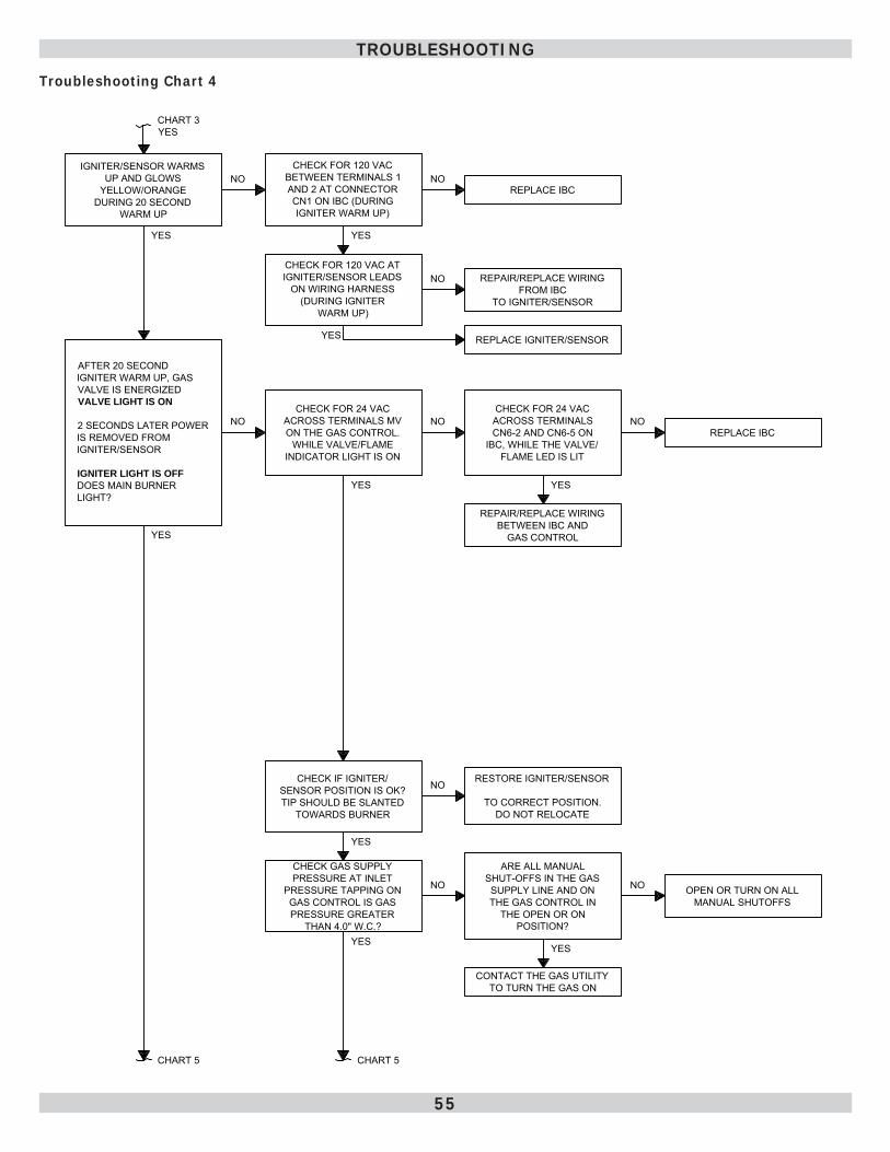
55
Troubleshooting Chart 4
IGNITER/SENSOR WARMSUP AND GLOWS
YELLOW/ORANGEDURING 20 SECOND
WARM UP
CHART 3YES
NOCHECK FOR 120 VAC
BETWEEN TERMINALS 1 AND 2 AT CONNECTOR CN1 ON IBC (DURING IGNITER WARM UP)
NOREPLACE IBC
YES
CHECK FOR 120 VAC AT IGNITER/SENSOR LEADS
ON WIRING HARNESS (DURING IGNITER
WARM UP)
NO REPAIR/REPLACE WIRING FROM IBC
TO IGNITER/SENSOR
YES REPLACE IGNITER/SENSOR
AFTER 20 SECOND IGNITER WARM UP, GAS VALVE IS ENERGIZED VALVE LIGHT IS ON
2 SECONDS LATER POWER IS REMOVED FROM IGNITER/SENSOR
IGNITER LIGHT IS OFFDOES MAIN BURNER LIGHT?
CHECK FOR 24 VAC ACROSS TERMINALS MV ON THE GAS CONTROL.
WHILE VALVE/FLAME INDICATOR LIGHT IS ON
NO NOCHECK FOR 24 VAC ACROSS TERMINALS CN6-2 AND CN6-5 ON
IBC, WHILE THE VALVE/FLAME LED IS LIT
NOREPLACE IBC
YES
REPAIR/REPLACE WIRING BETWEEN IBC AND
GAS CONTROL
YES
CHECK IF IGNITER/SENSOR POSITION IS OK?TIP SHOULD BE SLANTED
TOWARDS BURNER
RESTORE IGNITER/SENSOR
TO CORRECT POSITION.DO NOT RELOCATE
NO
YES
CHECK GAS SUPPLY PRESSURE AT INLET
PRESSURE TAPPING ON GAS CONTROL IS GAS PRESSURE GREATER
THAN 4.0" W.C.?
NO
ARE ALL MANUAL SHUT-OFFS IN THE GAS SUPPLY LINE AND ON THE GAS CONTROL IN
THE OPEN OR ON POSITION?
OPEN OR TURN ON ALL MANUAL SHUTOFFS
NO
YES
CONTACT THE GAS UTILITY TO TURN THE GAS ON
YES
CHART 5 CHART 5
YES
YES
TROUBLESHOOTING
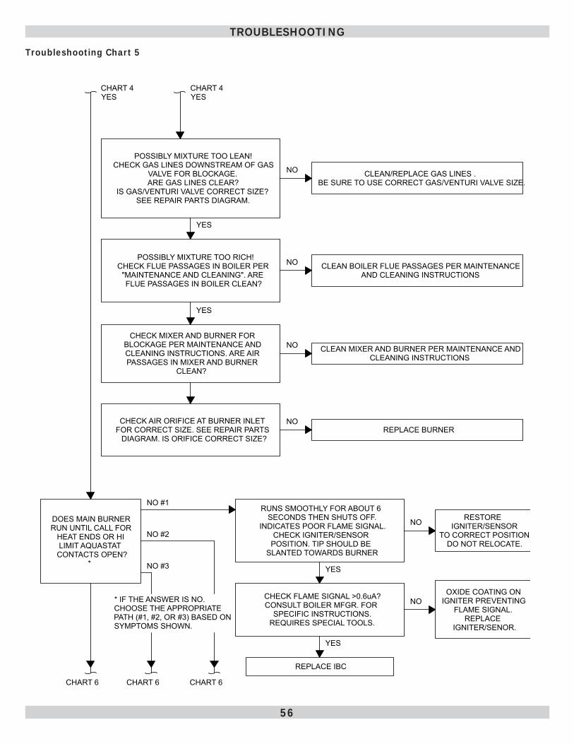
56
POSSIBLY MIXTURE TOO LEAN!CHECK GAS LINES DOWNSTREAM OF GAS
VALVE FOR BLOCKAGE.ARE GAS LINES CLEAR?
IS GAS/VENTURI VALVE CORRECT SIZE? SEE REPAIR PARTS DIAGRAM.
CLEAN/REPLACE GAS LINES .BE SURE TO USE CORRECT GAS/VENTURI VALVE SIZE.
NO
YES
POSSIBLY MIXTURE TOO RICH!CHECK FLUE PASSAGES IN BOILER PER
"MAINTENANCE AND CLEANING". ARE FLUE PASSAGES IN BOILER CLEAN?
NO CLEAN BOILER FLUE PASSAGES PER MAINTENANCE AND CLEANING INSTRUCTIONS
CHART 4YES
YES
CHECK MIXER AND BURNER FOR BLOCKAGE PER MAINTENANCE AND CLEANING INSTRUCTIONS. ARE AIR PASSAGES IN MIXER AND BURNER
CLEAN?
NO CLEAN MIXER AND BURNER PER MAINTENANCE AND CLEANING INSTRUCTIONS
CHECK AIR ORIFICE AT BURNER INLET FOR CORRECT SIZE. SEE REPAIR PARTS
DIAGRAM. IS ORIFICE CORRECT SIZE?REPLACE BURNER
NO
CHART 4YES
DOES MAIN BURNER RUN UNTIL CALL FOR
HEAT ENDS OR HI LIMIT AQUASTAT
CONTACTS OPEN?*
NO #1
NO #2
NO #3
RUNS SMOOTHLY FOR ABOUT 6 SECONDS THEN SHUTS OFF.
INDICATES POOR FLAME SIGNAL.CHECK IGNITER/SENSOR
POSITION. TIP SHOULD BE SLANTED TOWARDS BURNER
CHART 6
YES
CHECK FLAME SIGNAL >0.6uA?CONSULT BOILER MFGR. FOR
SPECIFIC INSTRUCTIONS.REQUIRES SPECIAL TOOLS.
YES
REPLACE IBC
* IF THE ANSWER IS NO. CHOOSE THE APPROPRIATE PATH (#1, #2, OR #3) BASED ON SYMPTOMS SHOWN.
RESTORE IGNITER/SENSOR
TO CORRECT POSITION.DO NOT RELOCATE.
NO
CHART 6 CHART 6
OXIDE COATING ON IGNITER PREVENTING
FLAME SIGNAL. REPLACE
IGNITER/SENOR.
NO
Troubleshooting Chart 5
TROUBLESHOOTING
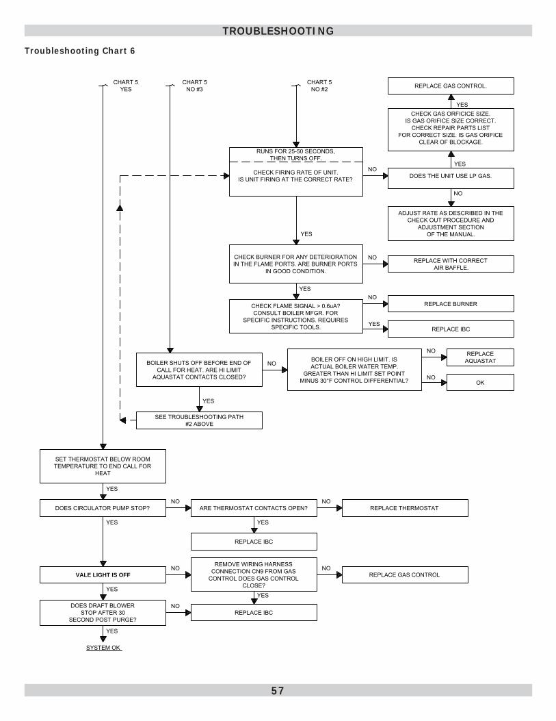
57
Troubleshooting Chart 6
RUNS FOR 25-50 SECONDS, THEN TURNS OFF.
CHECK FIRING RATE OF UNIT.IS UNIT FIRING AT THE CORRECT RATE?
NODOES THE UNIT USE LP GAS.
YES
NO
CHECK GAS ORFICICE SIZE.IS GAS ORIFICE SIZE CORRECT.
CHECK REPAIR PARTS LIST FOR CORRECT SIZE. IS GAS ORIFICE
CLEAR OF BLOCKAGE.
ADJUST RATE AS DESCRIBED IN THE CHECK OUT PROCEDURE AND
ADJUSTMENT SECTIONOF THE MANUAL.
CHART 5NO #2
YES
CHECK BURNER FOR ANY DETERIORATION IN THE FLAME PORTS. ARE BURNER PORTS
IN GOOD CONDITION.
NO REPLACE WITH CORRECT AIR BAFFLE.
YES
CHECK FLAME SIGNAL > 0.6uA?CONSULT BOILER MFGR. FOR
SPECIFIC INSTRUCTIONS. REQUIRES SPECIFIC TOOLS.
NO
YES
REPLACE BURNER
REPLACE IBC
BOILER SHUTS OFF BEFORE END OF CALL FOR HEAT. ARE HI LIMIT
AQUASTAT CONTACTS CLOSED?
NOBOILER OFF ON HIGH LIMIT. IS ACTUAL BOILER WATER TEMP.
GREATER THAN HI LIMIT SET POINT MINUS 30°F CONTROL DIFFERENTIAL?
NO
NO
REPLACEAQUASTAT
OK
YES
SEE TROUBLESHOOTING PATH #2 ABOVE
CHART 5NO #3
CHART 5YES
SET THERMOSTAT BELOW ROOM TEMPERATURE TO END CALL FOR
HEAT
DOES CIRCULATOR PUMP STOP?NO
ARE THERMOSTAT CONTACTS OPEN? REPLACE THERMOSTATNO
YES
REPLACE IBC
YES
VALE LIGHT IS OFF
REMOVE WIRING HARNESS CONNECTION CN9 FROM GAS
CONTROL DOES GAS CONTROL CLOSE?
NOREPLACE GAS CONTROL
NO
YES
YES
DOES DRAFT BLOWER STOP AFTER 30
SECOND POST PURGE?
NOREPLACE IBC
YES
YES
SYSTEM OK
YES
REPLACE GAS CONTROL.
TROUBLESHOOTING
58
Aluminum SeriesHigh Effi ciency Gas-Fired Boiler
DIELECTRIC ISOLATION & ANTIFREEZE PROTECTION
APPENDIX A - WATER QUALITY, WATER TREATMENT AND FREEZE PROTECTION
WARNINGFollow these instructions to prevent damage to boiler’s heat exchanger caused by inadequate dielectric isolation, incorrect water treatment or antifreeze application. Failure to comply could result in death or serious injury.
!
• Install boiler so gas ignition system components are protected from water (dripping, spraying, rain, etc) during appliance operation and service (circulator replacement, etc).
• DIELECTRIC ISOLATION
Two (2) 1-1/4” X 1-1/4” Female to female dielectric isolation unions are shipped loose in boiler parts bag. Install Dielectric Isolation unions at boiler supply line and return line. Install isolation fi ttings nearest boiler prior to system piping connections.
• WATER TREATMENT and ANTIFREEZE PROTECTION
MUST be applied for ALL aluminum series high effi ciency gas-fi red boilers using antifreeze protection.
59
System and Operating PrecautionsApplies to ALL Aluminum High Effi ciency Gas-Fired Water Boilers
Eliminate System LeaksContinuous addition of make-up water will constantly add oxygen to system. Eliminate all system leaks. All system leaks must be repaired immediately.
DO NOT use stop leak compounds. Leaks in threaded connections in aluminum boiler sections must be repaired immediately. Aluminum threads will not seal themselves.
Verify expansion tank is operational and properly sized. Undersized expansion tanks cause relief valve weeping and substantial make-up water addition.
Operation of this boiler in system containing signifi cant amounts of dissolved oxygen can cause severe heat exchanger corrosion damage.
This boiler is not designed for use in systems containing regular additions of make-up water. Regular additions of make-up water may cause severe heat exchanger damage. System leaks may not always be visible. An unseen system leak will become obvious if boiler pressure decreases when make-up valve is closed.
This boiler is designed for closed loop hydronic heat system ONLY! This boiler is not suitable for natural gravity type installations, or any other open type system.
Fill Water and ChemistryVerify water used to fi ll system meets these requirements:System fl uid pH maintained between 7.0 and 8.0. Maintain water hardness below 7 grains hardness. Filling with chlorinated potable water is acceptable. DO NOT fi ll boiler with water containing chlorine in excess of 100 ppm.DO NOT use inhibitors or other additives that are not listed in this addendum.Consult local water treatment specialist for recommendations if any of above requirements is outside stated ranges.
Clean System FirstBEFORE connecting boiler to heating system, clean and fl ush system thoroughly. Verify system is free of sediment, fl ux and any residual boiler water additives.
Systems having antifreeze not recommended must be completely fl ushed to ensure no old antifreeze remains. In older systems obviously discolored, murky or dirty water; or pH reading outside acceptable range (between 7.0 and 8.0) are indications the system should be cleaned or treated. Thoroughly fl ush system with clean water to remove any sediment or contaminants. Sludge and iron oxide deposits can cause rapid breakdown of inhibitors.
Flushing with clean water. If chemical cleaners are used, use only those recommended for use with aluminum boilers. Follow chemical cleaner manufacturer’s instructions completely.
DO NOT mix different manufacturer’s products.
60
System and Operating PrecautionsApplies to ALL Aluminum High Effi ciency Gas-Fired Water Boilers
General Guidelines When Using Antifreeze• Use only antifreeze products recommended
for use with aluminum boilers, as listed in this addendum. See Table 8.
• Continuous addition of make-up water will dilute power of antifreeze and change buffers ability to maintain pH.
• Flush old antifreeze from system. Flush boiler and system separately.
• Do not use antifreeze unless required.
• Antifreeze, if needed, must be of type listed on next page due to their operational characteristics of : type 356 T6 aluminum at operating temperatures between 20°F (-6.7°C) and 250°F (121°C). (See Table 8 for allowable products.)
• Always clean system prior to using antifreeze as stated in this supplement.
• Follow antifreeze manufacturer’s instructions for use, safe handling and storage of their products. Refer to MSDS (Material Safety Data Sheets) provided by antifreeze manufacturer for potential hazards and fi rst aid procedures for exposure or ingestion.
• Antifreeze will raise pH of hydronic solution in heating system above recommended level due to corrosion inhibitors. Solution must be treated to maintain a pH within recommended level. Follow antifreeze manufacturer’s instructions to adjust pH.
• If system has leaked, water and antifreeze chemistry will need to be adjusted. To avoid damage to boiler, check pH and chemistry of boiler solution and consult the antifreeze manufacturer for recommendations.
• Recommend taking pH reading annually, and adjusted as necessary. Follow antifreeze/inhibitor manufacturer’s instructions for details on how to adjust pH.
• Antifreeze solutions can break down over time. Failure to check antifreeze chemistry on annual basis may result in accelerated corrosion of boiler and other system components. Consult with antifreeze manufacturer for recommendations.
• Use of antifreeze in any boiler will reduce heating capacity as much as 10-20%. Take into consideration when sizing heating system, pumps and expansion tank. Consult antifreeze manufacturer’s literature for specifi c information on reduced capacity.
• Using antifreeze manufacturer’s instructions, determine freezing temperature needed and use correct amount of antifreeze. Never exceed 50% antifreeze by volume.
• Boiler operating pressure must remain below 15 psi for antifreeze solutions that specify a maximum of 250°F (121°C). Otherwise, increase system operating/tank pressure to 20 psig. Note: Refer to expansion tank manufacturer instructions for adjusting tank pressure.
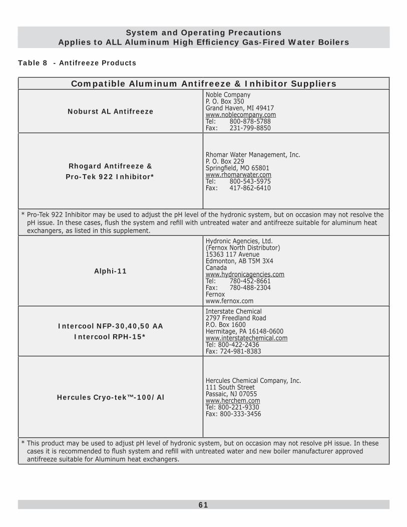
61
Compatible Aluminum Antifreeze & Inhibitor Suppliers
Noburst AL Antifreeze
Noble CompanyP. O. Box 350Grand Haven, MI 49417www.noblecompany.comTel: 800-878-5788Fax: 231-799-8850
Rhogard Antifreeze &Pro-Tek 922 Inhibitor*
Rhomar Water Management, Inc.P. O. Box 229Springfi eld, MO 65801www.rhomarwater.comTel: 800-543-5975Fax: 417-862-6410
* Pro-Tek 922 Inhibitor may be used to adjust the pH level of the hydronic system, but on occasion may not resolve the pH issue. In these cases, fl ush the system and refi ll with untreated water and antifreeze suitable for aluminum heat exchangers, as listed in this supplement.
Alphi-11
Hydronic Agencies, Ltd.(Fernox North Distributor)15363 117 AvenueEdmonton, AB T5M 3X4Canadawww.hydronicagencies.comTel: 780-452-8661Fax: 780-488-2304Fernoxwww.fernox.com
Intercool NFP-30,40,50 AAIntercool RPH-15*
Interstate Chemical2797 Freedland RoadP.O. Box 1600Hermitage, PA 16148-0600www.interstatechemical.comTel: 800-422-2436Fax: 724-981-8383
Hercules Cryo-tek™-100/Al
Hercules Chemical Company, Inc.111 South StreetPassaic, NJ 07055www.herchem.comTel: 800-221-9330Fax: 800-333-3456
* This product may be used to adjust pH level of hydronic system, but on occasion may not resolve pH issue. In these cases it is recommended to fl ush system and refi ll with untreated water and new boiler manufacturer approved antifreeze suitable for Aluminum heat exchangers.
Table 8 - Antifreeze Products
System and Operating PrecautionsApplies to ALL Aluminum High Effi ciency Gas-Fired Water Boilers
62
INSTALLATION AND CHECK-OUT CERTIFICATE
Boiler Model Serial # Date Installed___________
Measured BTU/HR input____________
Installation instructions have been followed
Checkout procedure and adjustments performed
Maintenance and Service issues reviewed with owner/ maintenance person
Installation booklet affi xed on or adjacent to boiler
Installer (Company)
Address
Phone
Installer’s Name
Signature
INSTALLATION AND CHECK-OUT CERTIFICATE
NOTES

CAC/BDP7310 West Morris St.
Indianapolis, IN. 46231