Embed Size (px)
Citation preview
Beason, R. C., T. J. Nohara, and P. Weber. 2010. Color vision as a model for precise altitude determination for avian radar. Proceedings of the 29th International Bird Strike Committee. Paper 12. Cairns, Australia. http://www.int-birdstrike.org/Cairns_Papers/IBSC29%20WP12.pdf
Color Vision as a Model for Precise Altitude Determination For Avian Radar Robert C. Beason1, Peter Weber2, Timothy J. Nohara3
1 Accipiter Radar Corporation, [email protected] 2 Accipiter Radar Technologies Inc., [email protected] 3 Accipiter Radar Technologies Inc., [email protected] Abstract Accurately measuring the altitude of birds in flight with radar is a challenge. Surveillance radars, with a fan-shaped beam pattern, provide little useful altitude information. Tracking radars provide precise altitude information but are limited to monitoring the location and altitude of single or very few targets simultaneously. One compromise is to use a parabolic dish antenna, which provides simultaneous location and altitude information for every target. For comparison, an unmodified array antenna has a vertical beamwidth of 10° above the ground, producing an altitude uncertainty of ± 5°. A 4° dish antenna would have ± 2 ° uncertainty. As the ditching of US Air’s flight 1549 graphically illustrated, we need more precise information on the altitude of birds when they are in the vicinity of aircraft. We previously illustrated the use of automated radar to detect and warn of near collisions between birds and aircraft but the value of the alerts is restricted to within 2 km because altitude precision degrades with range. We developed a radar system based on a single transceiver and a multi-beam antenna system that produces two identical antenna patterns differing only in elevation angle. The outgoing and returning signals are electronically switched between the two beams. This provides expanded vertical coverage (compared to a single dish antenna) and greatly improved precision of measuring altitude. For example, two 4° beams that overlap at their 3 dB points would have 8° vertical coverage. With the bottom of the lower beam 2° above the horizontal to reduce ground clutter, this would provide coverage to 10°, which is comparable to an array antenna. The technique to determine the altitude of a bird within the multiple beam patterns is analogous to vertebrate color vision. The altitude within the overlap is determined by the relative intensities of the returned signals received by the two beams in a way similar to color being determined based on the relative stimulation of the visual pigments in two color photoreceptors. The amount of beam overlap determines the resolution within the region of overlap just as it does with retinal cones. Beams with the optimum overlap produce higher resolution than beams with non-optimal overlap. In our testing of an experimental antenna, we found that we could achieve an angular resolution of approximately ± 0.75°, a 3-fold increase compared to a single dish antenna; and 7-fold improvement compared to an array antenna. The areas outside the overlap have a resolution of ±1° (the width of the non-overlap). Greater vertical coverage and resolution could be gained, in theory, by additional beams, but the mechanics of the antenna system become more challenging. A dual-beam antenna system provides at least a 7-fold improvement in altitude precision of birds flying through the radar’s coverage compared with an array antenna without loss of targets or area coverage. This type of antenna system has been integrated with existing marine radars to provide affordable 3D capabilities. Key words Avian radar, Altitude measurement, Bird strike, Radar antenna, Height-finding, BASH
Beason, Weber, Nohara Precision altitude measurements
2
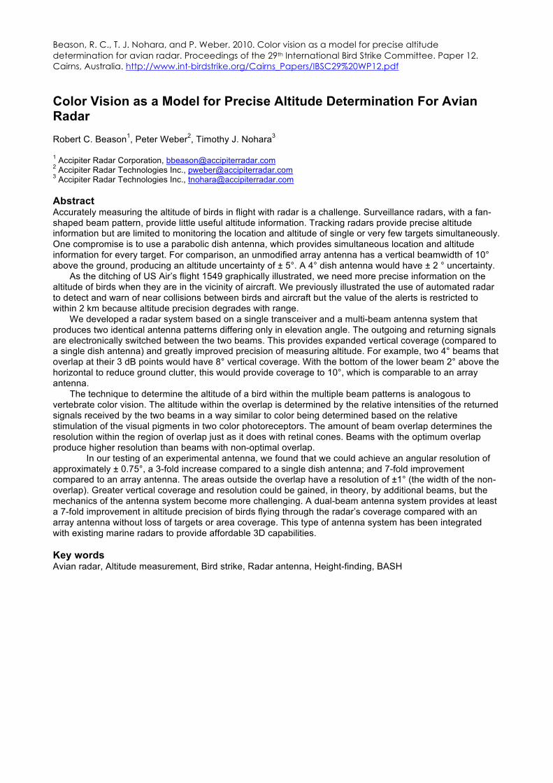
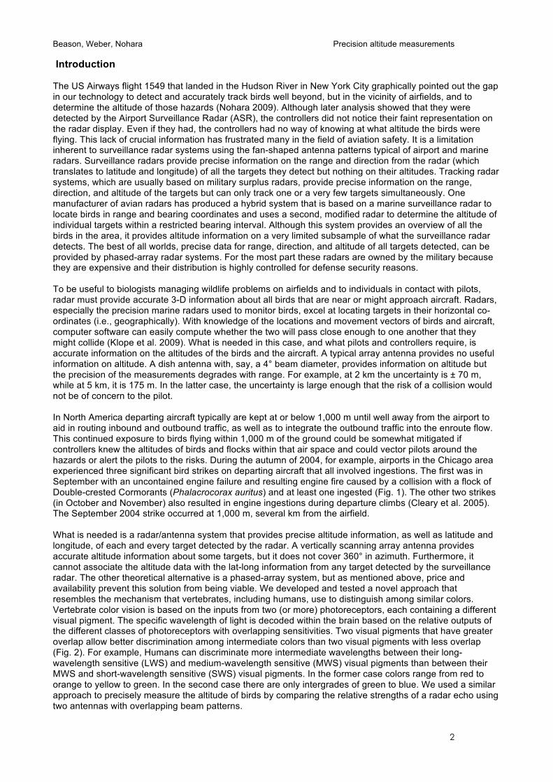
Introduction The US Airways flight 1549 that landed in the Hudson River in New York City graphically pointed out the gap in our technology to detect and accurately track birds well beyond, but in the vicinity of airfields, and to determine the altitude of those hazards (Nohara 2009). Although later analysis showed that they were detected by the Airport Surveillance Radar (ASR), the controllers did not notice their faint representation on the radar display. Even if they had, the controllers had no way of knowing at what altitude the birds were flying. This lack of crucial information has frustrated many in the field of aviation safety. It is a limitation inherent to surveillance radar systems using the fan-shaped antenna patterns typical of airport and marine radars. Surveillance radars provide precise information on the range and direction from the radar (which translates to latitude and longitude) of all the targets they detect but nothing on their altitudes. Tracking radar systems, which are usually based on military surplus radars, provide precise information on the range, direction, and altitude of the targets but can only track one or a very few targets simultaneously. One manufacturer of avian radars has produced a hybrid system that is based on a marine surveillance radar to locate birds in range and bearing coordinates and uses a second, modified radar to determine the altitude of individual targets within a restricted bearing interval. Although this system provides an overview of all the birds in the area, it provides altitude information on a very limited subsample of what the surveillance radar detects. The best of all worlds, precise data for range, direction, and altitude of all targets detected, can be provided by phased-array radar systems. For the most part these radars are owned by the military because they are expensive and their distribution is highly controlled for defense security reasons. To be useful to biologists managing wildlife problems on airfields and to individuals in contact with pilots, radar must provide accurate 3-D information about all birds that are near or might approach aircraft. Radars, especially the precision marine radars used to monitor birds, excel at locating targets in their horizontal co-ordinates (i.e., geographically). With knowledge of the locations and movement vectors of birds and aircraft, computer software can easily compute whether the two will pass close enough to one another that they might collide (Klope et al. 2009). What is needed in this case, and what pilots and controllers require, is accurate information on the altitudes of the birds and the aircraft. A typical array antenna provides no useful information on altitude. A dish antenna with, say, a 4° beam diameter, provides information on altitude but the precision of the measurements degrades with range. For example, at 2 km the uncertainty is ± 70 m, while at 5 km, it is 175 m. In the latter case, the uncertainty is large enough that the risk of a collision would not be of concern to the pilot. In North America departing aircraft typically are kept at or below 1,000 m until well away from the airport to aid in routing inbound and outbound traffic, as well as to integrate the outbound traffic into the enroute flow. This continued exposure to birds flying within 1,000 m of the ground could be somewhat mitigated if controllers knew the altitudes of birds and flocks within that air space and could vector pilots around the hazards or alert the pilots to the risks. During the autumn of 2004, for example, airports in the Chicago area experienced three significant bird strikes on departing aircraft that all involved ingestions. The first was in September with an uncontained engine failure and resulting engine fire caused by a collision with a flock of Double-crested Cormorants (Phalacrocorax auritus) and at least one ingested (Fig. 1). The other two strikes (in October and November) also resulted in engine ingestions during departure climbs (Cleary et al. 2005). The September 2004 strike occurred at 1,000 m, several km from the airfield. What is needed is a radar/antenna system that provides precise altitude information, as well as latitude and longitude, of each and every target detected by the radar. A vertically scanning array antenna provides accurate altitude information about some targets, but it does not cover 360° in azimuth. Furthermore, it cannot associate the altitude data with the lat-long information from any target detected by the surveillance radar. The other theoretical alternative is a phased-array system, but as mentioned above, price and availability prevent this solution from being viable. We developed and tested a novel approach that resembles the mechanism that vertebrates, including humans, use to distinguish among similar colors. Vertebrate color vision is based on the inputs from two (or more) photoreceptors, each containing a different visual pigment. The specific wavelength of light is decoded within the brain based on the relative outputs of the different classes of photoreceptors with overlapping sensitivities. Two visual pigments that have greater overlap allow better discrimination among intermediate colors than two visual pigments with less overlap (Fig. 2). For example, Humans can discriminate more intermediate wavelengths between their long-wavelength sensitive (LWS) and medium-wavelength sensitive (MWS) visual pigments than between their MWS and short-wavelength sensitive (SWS) visual pigments. In the former case colors range from red to orange to yellow to green. In the second case there are only intergrades of green to blue. We used a similar approach to precisely measure the altitude of birds by comparing the relative strengths of a radar echo using two antennas with overlapping beam patterns.
Beason, Weber, Nohara Precision altitude measurements
3
Figure 1. An MD-80 engine that was damaged and caught fire from a strike with a Double-crested Cormorant at 1,000 m altitude. From Cleary et al. 2005.
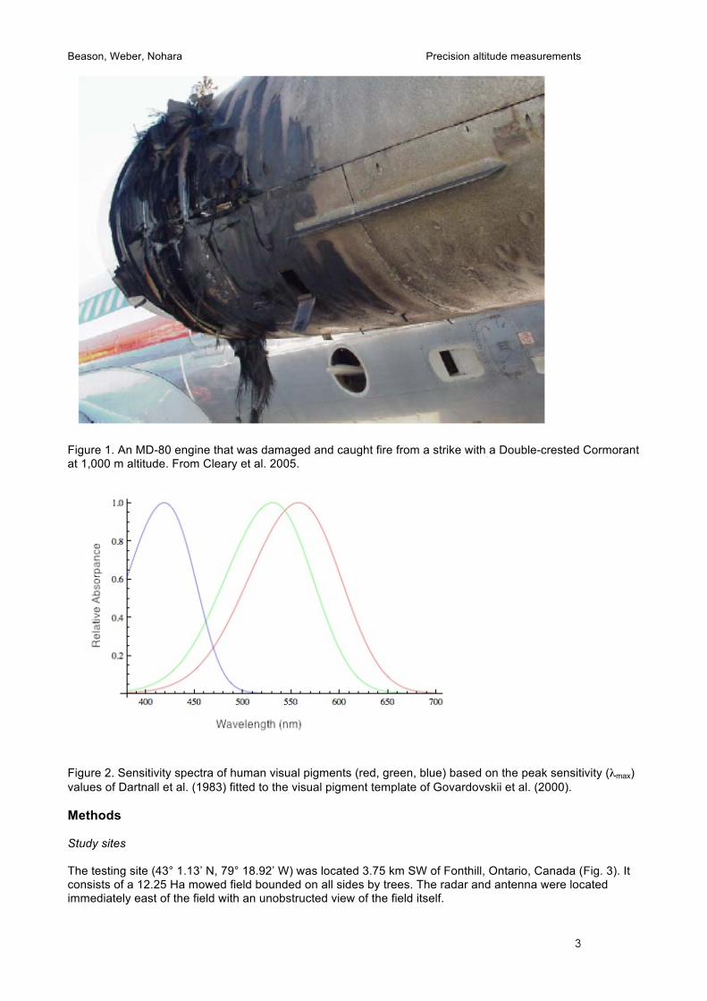
Figure 2. Sensitivity spectra of human visual pigments (red, green, blue) based on the peak sensitivity (λmax) values of Dartnall et al. (1983) fitted to the visual pigment template of Govardovskii et al. (2000). Methods Study sites The testing site (43° 1.13’ N, 79° 18.92’ W) was located 3.75 km SW of Fonthill, Ontario, Canada (Fig. 3). It consists of a 12.25 Ha mowed field bounded on all sides by trees. The radar and antenna were located immediately east of the field with an unobstructed view of the field itself.
Beason, Weber, Nohara Precision altitude measurements
4
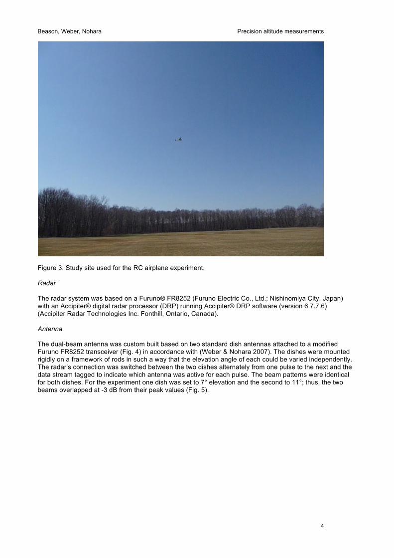
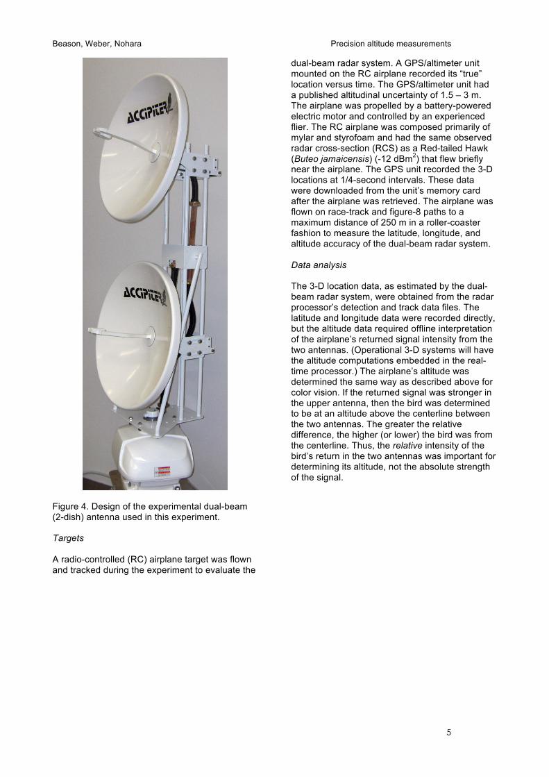
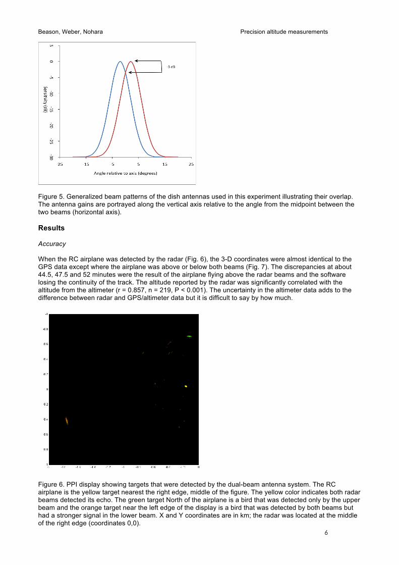
Figure 3. Study site used for the RC airplane experiment. Radar The radar system was based on a Furuno® FR8252 (Furuno Electric Co., Ltd.; Nishinomiya City, Japan) with an Accipiter® digital radar processor (DRP) running Accipiter® DRP software (version 6.7.7.6) (Accipiter Radar Technologies Inc. Fonthill, Ontario, Canada). Antenna The dual-beam antenna was custom built based on two standard dish antennas attached to a modified Furuno FR8252 transceiver (Fig. 4) in accordance with (Weber & Nohara 2007). The dishes were mounted rigidly on a framework of rods in such a way that the elevation angle of each could be varied independently. The radar’s connection was switched between the two dishes alternately from one pulse to the next and the data stream tagged to indicate which antenna was active for each pulse. The beam patterns were identical for both dishes. For the experiment one dish was set to 7° elevation and the second to 11°; thus, the two beams overlapped at -3 dB from their peak values (Fig. 5).
Beason, Weber, Nohara Precision altitude measurements
5
Figure 4. Design of the experimental dual-beam (2-dish) antenna used in this experiment. Targets A radio-controlled (RC) airplane target was flown and tracked during the experiment to evaluate the
dual-beam radar system. A GPS/altimeter unit mounted on the RC airplane recorded its “true” location versus time. The GPS/altimeter unit had a published altitudinal uncertainty of 1.5 – 3 m. The airplane was propelled by a battery-powered electric motor and controlled by an experienced flier. The RC airplane was composed primarily of mylar and styrofoam and had the same observed radar cross-section (RCS) as a Red-tailed Hawk (Buteo jamaicensis) (-12 dBm2) that flew briefly near the airplane. The GPS unit recorded the 3-D locations at 1/4-second intervals. These data were downloaded from the unit’s memory card after the airplane was retrieved. The airplane was flown on race-track and figure-8 paths to a maximum distance of 250 m in a roller-coaster fashion to measure the latitude, longitude, and altitude accuracy of the dual-beam radar system. Data analysis The 3-D location data, as estimated by the dual-beam radar system, were obtained from the radar processor’s detection and track data files. The latitude and longitude data were recorded directly, but the altitude data required offline interpretation of the airplane’s returned signal intensity from the two antennas. (Operational 3-D systems will have the altitude computations embedded in the real-time processor.) The airplane’s altitude was determined the same way as described above for color vision. If the returned signal was stronger in the upper antenna, then the bird was determined to be at an altitude above the centerline between the two antennas. The greater the relative difference, the higher (or lower) the bird was from the centerline. Thus, the relative intensity of the bird’s return in the two antennas was important for determining its altitude, not the absolute strength of the signal.
Beason, Weber, Nohara Precision altitude measurements
6
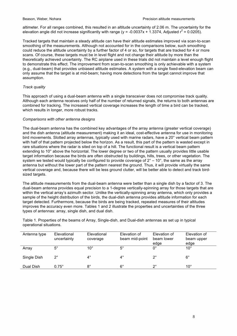
Figure 5. Generalized beam patterns of the dish antennas used in this experiment illustrating their overlap. The antenna gains are portrayed along the vertical axis relative to the angle from the midpoint between the two beams (horizontal axis). Results Accuracy When the RC airplane was detected by the radar (Fig. 6), the 3-D coordinates were almost identical to the GPS data except where the airplane was above or below both beams (Fig. 7). The discrepancies at about 44.5, 47.5 and 52 minutes were the result of the airplane flying above the radar beams and the software losing the continuity of the track. The altitude reported by the radar was significantly correlated with the altitude from the altimeter (r = 0.857, n = 219, P < 0.001). The uncertainty in the altimeter data adds to the difference between radar and GPS/altimeter data but it is difficult to say by how much.
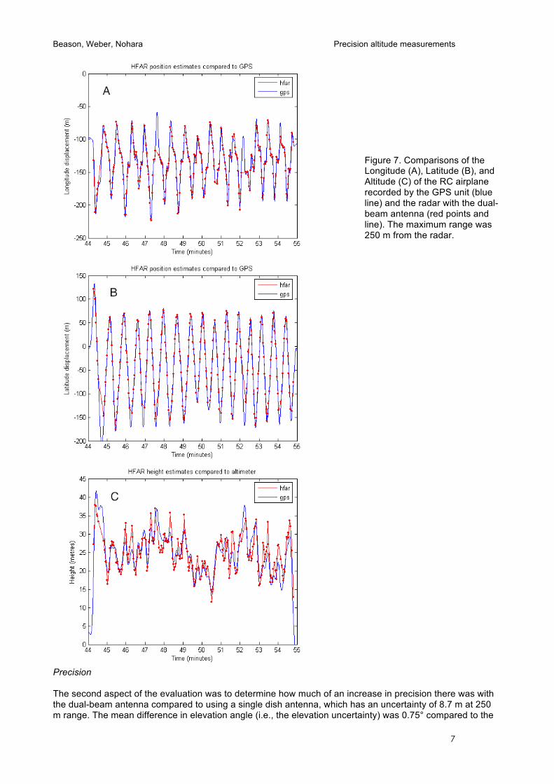
Figure 6. PPI display showing targets that were detected by the dual-beam antenna system. The RC airplane is the yellow target nearest the right edge, middle of the figure. The yellow color indicates both radar beams detected its echo. The green target North of the airplane is a bird that was detected only by the upper beam and the orange target near the left edge of the display is a bird that was detected by both beams but had a stronger signal in the lower beam. X and Y coordinates are in km; the radar was located at the middle of the right edge (coordinates 0,0).
Beason, Weber, Nohara Precision altitude measurements
7
Figure 7. Comparisons of the Longitude (A), Latitude (B), and Altitude (C) of the RC airplane recorded by the GPS unit (blue line) and the radar with the dual-beam antenna (red points and line). The maximum range was 250 m from the radar.
Precision The second aspect of the evaluation was to determine how much of an increase in precision there was with the dual-beam antenna compared to using a single dish antenna, which has an uncertainty of 8.7 m at 250 m range. The mean difference in elevation angle (i.e., the elevation uncertainty) was 0.75° compared to the
Beason, Weber, Nohara Precision altitude measurements
8
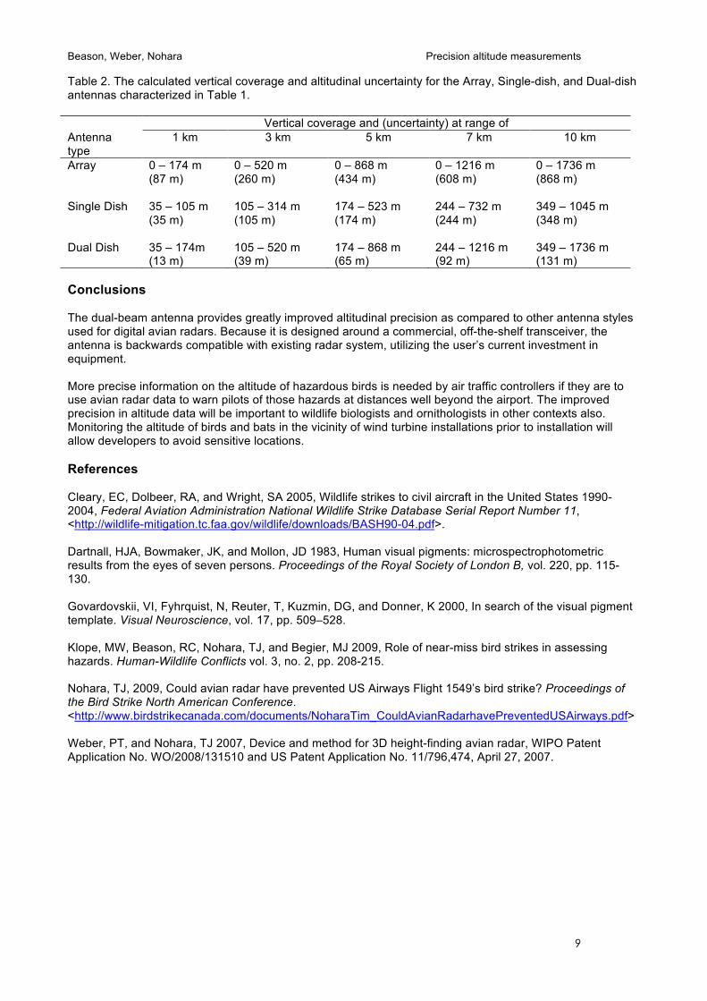
altimeter. For all ranges combined, this resulted in an altitude uncertainty of 2.06 m. The uncertainty for the elevation angle did not increase significantly with range (y = -0.0037x + 1.3374, Adjusted r2 = 0.0205). Tracked targets that maintain a steady altitude can have their altitude estimates improved via scan-to-scan smoothing of the measurements. Although not accounted for in the comparisons below, such smoothing could reduce the altitude uncertainty by a further factor of 4 or so, for targets that are tracked for 4 or more scans. Of course, these targets must be in level flight and not change their altitude by more than the theoretically achieved uncertainty. The RC airplane used in these trials did not maintain a level enough flight to demonstrate this effect. The improvement from scan-to-scan smoothing is only achievable with a system (e.g., dual-beam) that provides unbiased altitude estimates. A system with a single fixed-elevation beam can only assume that the target is at mid-beam; having more detections from the target cannot improve that assumption. Track quality This approach of using a dual-beam antenna with a single transceiver does not compromise track quality. Although each antenna receives only half of the number of returned signals, the returns to both antennas are combined for tracking. The increased vertical coverage increases the length of time a bird can be tracked, which results in longer, more robust tracks. Comparisons with other antenna designs The dual-beam antenna has the combined key advantages of the array antenna (greater vertical coverage) and the dish antenna (altitude measurement) making it an ideal, cost-effective antenna for use in monitoring bird movements. Slotted array antennas, typically used with marine radars, have a 20° vertical beam pattern with half of that pattern projected below the horizon. As a result, this part of the pattern is wasted except in rare situations where the radar is sited on top of a hill. The functional result is a vertical beam pattern extending to 10° above the horizontal. The lower degree or two of the pattern usually provides little usable target information because the birds are often obstructed by buildings, hills, trees, or other vegetation. The system we tested would typically be configured to provide coverage of 2° – 10°, the same as the array antenna but without the lower part of the pattern nearest the ground. Thus, it will provide virtually the same vertical coverage and, because there will be less ground clutter, will be better able to detect and track bird-sized targets. The altitude measurements from the dual-beam antenna were better than a single dish by a factor of 3. The dual-beam antenna provides equal precision to a 1-degree vertically-spinning array for those targets that are within the vertical array’s azimuth sector. Unlike the vertically-spinning array antenna, which only provides a sample of the height distribution of the birds, the dual-dish antenna provides altitude information for each target detected. Furthermore, because the birds are being tracked, repeated measures of their altitudes improves the accuracy even more. Tables 1 and 2 illustrate the properties and uncertainties of the three types of antennas: array, single dish, and dual dish. Table 1. Properties of the beams of Array, Single-dish, and Dual-dish antennas as set up in typical operational situations. Antenna type Elevational
uncertainty Elevational coverage
Elevation of beam mid-point
Elevation of beam lower edge
Elevation of beam upper edge
Array
5° 10° 5° 0° 10°
Single Dish
2° 4° 4° 2° 6°
Dual Dish 0.75° 8° 6° 2° 10°
Beason, Weber, Nohara Precision altitude measurements
9
Table 2. The calculated vertical coverage and altitudinal uncertainty for the Array, Single-dish, and Dual-dish antennas characterized in Table 1. Vertical coverage and (uncertainty) at range of Antenna type
1 km 3 km 5 km 7 km 10 km
Array
0 – 174 m (87 m)
0 – 520 m (260 m)
0 – 868 m (434 m)
0 – 1216 m (608 m)
0 – 1736 m (868 m)
Single Dish
35 – 105 m (35 m)
105 – 314 m (105 m)
174 – 523 m (174 m)
244 – 732 m (244 m)
349 – 1045 m (348 m)
Dual Dish 35 – 174m (13 m)
105 – 520 m (39 m)
174 – 868 m (65 m)
244 – 1216 m (92 m)
349 – 1736 m (131 m)
Conclusions The dual-beam antenna provides greatly improved altitudinal precision as compared to other antenna styles used for digital avian radars. Because it is designed around a commercial, off-the-shelf transceiver, the antenna is backwards compatible with existing radar system, utilizing the user’s current investment in equipment. More precise information on the altitude of hazardous birds is needed by air traffic controllers if they are to use avian radar data to warn pilots of those hazards at distances well beyond the airport. The improved precision in altitude data will be important to wildlife biologists and ornithologists in other contexts also. Monitoring the altitude of birds and bats in the vicinity of wind turbine installations prior to installation will allow developers to avoid sensitive locations. References Cleary, EC, Dolbeer, RA, and Wright, SA 2005, Wildlife strikes to civil aircraft in the United States 1990-2004, Federal Aviation Administration National Wildlife Strike Database Serial Report Number 11, <http://wildlife-mitigation.tc.faa.gov/wildlife/downloads/BASH90-04.pdf>. Dartnall, HJA, Bowmaker, JK, and Mollon, JD 1983, Human visual pigments: microspectrophotometric results from the eyes of seven persons. Proceedings of the Royal Society of London B, vol. 220, pp. 115-130. Govardovskii, VI, Fyhrquist, N, Reuter, T, Kuzmin, DG, and Donner, K 2000, In search of the visual pigment template. Visual Neuroscience, vol. 17, pp. 509–528. Klope, MW, Beason, RC, Nohara, TJ, and Begier, MJ 2009, Role of near-miss bird strikes in assessing hazards. Human-Wildlife Conflicts vol. 3, no. 2, pp. 208-215. Nohara, TJ, 2009, Could avian radar have prevented US Airways Flight 1549’s bird strike? Proceedings of the Bird Strike North American Conference. <http://www.birdstrikecanada.com/documents/NoharaTim_CouldAvianRadarhavePreventedUSAirways.pdf> Weber, PT, and Nohara, TJ 2007, Device and method for 3D height-finding avian radar, WIPO Patent Application No. WO/2008/131510 and US Patent Application No. 11/796,474, April 27, 2007.