Embed Size (px)
Citation preview

CS1000-UM-251-04-9370 1
CS1000COLOR IMAGE SCANNER
SERVICE MANUAL
CS1000-UM-251-01-9370 2
Service Manual Licensing Agreement
Graphtec Corporation ("Graphtec") grants permission for customers to use this Service Manual ("this Service
Manual") provided together with these stipulations within Japan only in accordance with the conditions
described below, and requires customers to agree to the terms below.
1. Copyrights
All copyrights in this Service Manual remain the property of Graphtec.
2. Terms of Use
Customers may not export or carry this Service Manual outside Japan.
3. Copying or Modification
(1) Customers may make copies of this Service Manual for the purpose of backing up. The customer
must indicate the copyrights for this Service Manual on all copies made.
(2) Customers may not alter, compile, amend, or otherwise adapt this Service Manual
4. Third Party Usage
Customers may not permit reuse, assignment, transfer, or any other form of disposal of this Service
Manual or usage rights to a third party.
5. Warranty
(1) If this Service Manual does not work due to the physical faults of the storage media of this Service
Manual, contact the retailer from which the product was purchased. In cases where physical faults
are the responsibility of Graphtec, replacement will be made free of charge.
(2) Replacement as described in the previous section 5.(1) is Graphtec's only guarantee regarding the
storage media of this Service Manual.
(3) Graphtec supplies this Service Manual "as is." Graphtec and its suppliers do not guarantee the
performance or results that may be obtained by customers using this Service Manual. Similarly,
Graphtec and its suppliers make no explicit or implied guarantee of non-violation of rights by third
parties, merchantability, or suitability for a particular purpose. Graphtec and its suppliers can accept
no liability for any form of circumstantial, incidental, or specific damages that may arise. Graphtec
and its suppliers can accept no liability even if the retailer indicates the possibility of such damages
occurring. No liability can be accepted for claims against the rights of third parties.
CS1000-UM-251-9370 2
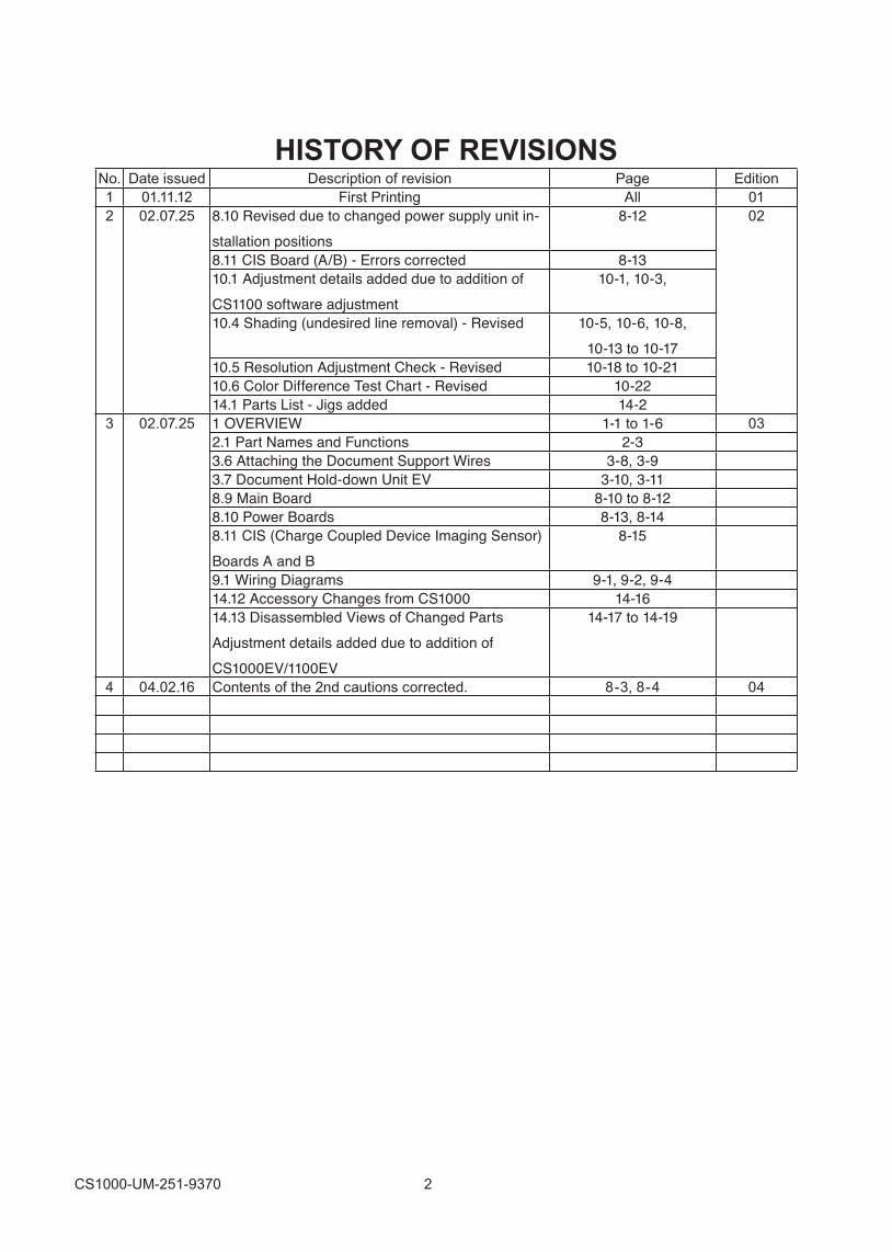
HISTORY OF REVISIONSNo. Date issued Description of revision Page Edition1 01.11.12 First Printing All 012 02.07.25 8.10 Revised due to changed power supply unit in-
stallation positions8-12 02
8.11 CIS Board (A/B) - Errors corrected 8-1310.1 Adjustment details added due to addition of CS1100 software adjustment
10-1, 10-3,
10.4 Shading (undesired line removal) - Revised 10-5, 10-6, 10-8,10-13 to 10-17
10.5 Resolution Adjustment Check - Revised 10-18 to 10-2110.6 Color Difference Test Chart - Revised 10-2214.1 Parts List - Jigs added 14-2
3 02.07.25 1 OVERVIEW 1-1 to 1-6 032.1 Part Names and Functions 2-33.6 Attaching the Document Support Wires 3-8, 3-93.7 Document Hold-down Unit EV 3-10, 3-118.9 Main Board 8-10 to 8-128.10 Power Boards 8-13, 8-148.11 CIS (Charge Coupled Device Imaging Sensor)Boards A and B
8-15
9.1 Wiring Diagrams 9-1, 9-2, 9-414.12 Accessory Changes from CS1000 14-1614.13 Disassembled Views of Changed PartsAdjustment details added due to addition ofCS1000EV/1100EV
14-17 to 14-19
4 04.02.16 Contents of the 2nd cautions corrected. 8-3, 8-4 04
CS1000-UM-251-01-9370 4
CONTENTS
Service Manual Licensing Agreement .................................................................................. 2
1. OVERVIEW ...................................................................................................................1-11.1 Features ...................................................................................................................................... 1-1
CS1000 Features ........................................................................................................................ 1-1CS1000EV Series Features ........................................................................................................ 1-1
1.2 Additional Functions of CS1000EV Series ................................................................................. 1-21.3 Cautions for CS1000EV Series .................................................................................................. 1-21.4 Product Differences .................................................................................................................... 1-21.5 Standard Specifications .............................................................................................................. 1-31.3 External View .............................................................................................................................. 1-41.4 System Requirements ................................................................................................................ 1-6
2. PART NAMES AND FUNCTIONS ................................................................................2-12.1 Part Names and Functions ......................................................................................................... 2-1
Front View ................................................................................................................................... 2-1Control panel .............................................................................................................................. 2-2Rear View ................................................................................................................................... 2-3
2.2 Unpacking the Scanner .............................................................................................................. 2-4
3. PREPARING TO OPERATE THE SCANNER ..............................................................3-13.1 Assembling the Scanner ............................................................................................................. 3-13.2 Connecting the Scanner to a Power Supply ............................................................................... 3-33.3 Connecting the SCSI Cable ........................................................................................................ 3-4
Compatible Cables ..................................................................................................................... 3-4Connection Procedure ................................................................................................................ 3-4
3.4 Setting the ID Number ................................................................................................................ 3-63.5 Turning the Scanner On or Off .................................................................................................... 3-73.6 Attaching the Document Support Wires ...................................................................................... 3-83.7 Document Hold-down Unit EV .................................................................................................. 3-10
Storing the Document Hold-down Unit EV................................................................................ 3-10Attaching the hooks (for CS1000EV and CS1100EV with stand *) ............................................ 3-11Replacement method................................................................................................................. 3-11Distance correction method ....................................................................................................... 3-11
4. OPERATION AND CONNECTION...............................................................................4-14.1 Connecting the Scanner to a Computer ..................................................................................... 4-1
Connecting the CS1000 to a Computer for the First Time .......................................................... 4-14.2 Checking the Interface Connection ............................................................................................. 4-74.3 Installing the Scanning Master 21+ Application .......................................................................... 4-94.4 Installing the Scanning Master Copy Color Application ............................................................ 4-104.5 Document Types Compatible with the CS1000 ......................................................................... 4-11
Compatible Media Widths for Scanning ..................................................................................... 4-11Compatible Media Lengths for Scanning ................................................................................... 4-11Compatible Grades & Thickness for Scanning .......................................................................... 4-11
4.6 Loading a Document ................................................................................................................. 4-12For standard-size documents ................................................................................................... 4-12
CS1000-UM-251-01-9370 5
4.7 Using the Carrier Sheet ............................................................................................................ 4-134.8 Scanner Driver Software’s Compatibility with Windows 2000 .................................................. 4-144.9 How to Obtain (Install) the ASPI Manager ................................................................................ 4-15
1. What you will need................................................................................................................ 4-152. How to obtain ASPI Manager ................................................................................................ 4-153. How to install ASPI Manager ................................................................................................ 4-15
4.10 Checking the ASPI Layer .......................................................................................................... 4-164.11 Checking Windows 2000 ASPI32 Status and Starting the Software ........................................ 4-17
If “Running” does not appear (Windows 2000 ASPI32 is not running), .................................... 4-184.12 Changing Transfer Rate with the AVA-2915LP (Ultra SCSI-compliant) .................................... 4-204.13 Factory Settings ........................................................................................................................ 4-22
DIP Switch ................................................................................................................................ 4-22ID Number ................................................................................................................................ 4-22
5. DAILY MAINTENANCE ................................................................................................5-15.1 Cleaning the Image Sensors ...................................................................................................... 5-15.2 Cleaning the Paper Sensors ....................................................................................................... 5-35.3 Cleaning the Document Hold-Down Unit .................................................................................... 5-45.4 Removing a Jammed Document ................................................................................................ 5-5
6. RECOMMENDED PARTS LIST ...................................................................................6-1
7. LIST OF JIGS AND TOOLS .........................................................................................7-17.1 Jigs ............................................................................................................................................. 7-17.2 Tools ........................................................................................................................................... 7-17.3 Other ........................................................................................................................................... 7-1
8. DISASSEMBLING AND ADJUSTING MECHANICAL PARTS ......................................8-18.1 Considerations before starting disassembly ............................................................................... 8-18.2 Document Hold-down Unit .......................................................................................................... 8-28.3 CS Retaining Plate ..................................................................................................................... 8-48.4 Side Covers ................................................................................................................................ 8-58.5 Top Cover ................................................................................................................................... 8-68.6 Front Cover ................................................................................................................................. 8-78.7 Rear Cover ................................................................................................................................. 8-88.8 Bottom Plates, Large and Small ................................................................................................. 8-98.9 Main Board ............................................................................................................................... 8-10
CS1000/1000EV disassembly procedure ................................................................................. 8-10When securing the main board to the jig (BSB-335) ................................................................ 8-10When detaching the main board completely (not for securing it to the jig) ................................ 8-11CS1100EV disassembly procedure .......................................................................................... 8-12
8.10 Power Boards ........................................................................................................................... 8-138.11 CIS (Charge Coupled Device Imaging Sensor) Boards A and B .............................................. 8-15
CS1000/1000EV disassembly procedure ................................................................................. 8-15CS1100EV disassembly procedure .......................................................................................... 8-15
8.12 Cooling Fan .............................................................................................................................. 8-168.13 Separator Plates ....................................................................................................................... 8-178.14 Pinch Roller Units ..................................................................................................................... 8-188.15 Front Guide ............................................................................................................................... 8-208.16 Rear Guide ............................................................................................................................... 8-21
CS1000-UM-251-01-9370 6
8.17 Control Panel ............................................................................................................................ 8-228.18 Cover Open Sensor .................................................................................................................. 8-238.19 Front and Rear Paper Detection Sensors ................................................................................. 8-248.20 Motor ......................................................................................................................................... 8-26
Adjusting the Tension Belt ........................................................................................................ 8-278.21 Pulleys ...................................................................................................................................... 8-28
Adjusting the Tension Belt ........................................................................................................ 8-288.22 Drive Rollers ............................................................................................................................. 8-298.23 Image Sensor Unit .................................................................................................................... 8-30
Replacing the Entire Image Sensor Unit ................................................................................... 8-30Replacing the Glass Base Unit Only ......................................................................................... 8-33
9. BOARDS AND ELECTRICAL COMPONENTS .............................................................9-19.1 Wiring Diagrams ......................................................................................................................... 9-1
Overall Configuration (CS1000/1000ES) .................................................................................... 9-1Overall Configuration (CS1100ES) ............................................................................................. 9-2Component Layout on the Main Board ....................................................................................... 9-3Power Unit Wiring ....................................................................................................................... 9-4
9.2 Power Supply Unit ...................................................................................................................... 9-51. Checking Voltage Levels ........................................................................................................ 9-5
9.3 Main Control Board ..................................................................................................................... 9-61. Precautions for replacing the main board ............................................................................... 9-62. Checking voltage levels .......................................................................................................... 9-63. LED status .............................................................................................................................. 9-64. Replacing the main board ....................................................................................................... 9-6
9.4 At-a-glance Guide to Adjustment Functions ............................................................................... 9-8Key operations ............................................................................................................................ 9-8
9.5 Downloading the Boot Program .................................................................................................. 9-91. Items required to download the boot program ........................................................................ 9-92. Procedure ............................................................................................................................... 9-9
9.6 Downloading Firmware ............................................................................................................. 9-101. Items required to download firmware .................................................................................... 9-102. Procedure ............................................................................................................................. 9-10
9.7 Test Mode .................................................................................................................................. 9-111. Procedure ..............................................................................................................................9-11
10. ADJUSTMENTS WITH SOFTWARE ........................................................................10-110.1 Starting the Software ................................................................................................................ 10-110.2 Preparations before Making Adjustments ................................................................................. 10-310.3 Preparing a Test Chart .............................................................................................................. 10-410.4 Making Adjustments .................................................................................................................. 10-5
1. Shading (white correction) .................................................................................................... 10-52. Feed distance adjustment ..................................................................................................... 10-63. Position adjustment .............................................................................................................. 10-84. Shading (undesired color line removal) .............................................................................. 10-135. Shading (undesired gray line removal) ............................................................................... 10-16
10.5 Resolution adjustment check .................................................................................................. 10-181. Paper-feed distance accuracy check .................................................................................. 10-182. Image-sensor offset (joint accuracy) ................................................................................... 10-183. Offset check ........................................................................................................................ 10-18
CS1000-UM-251-01-9370 7
4. Resolution check ................................................................................................................ 10-185. Checking sensor color density (using a color test chart) .................................................... 10-19
10.6 Color difference measurement chart ...................................................................................... 10-22
11. TROUBLESHOOTING .............................................................................................. 11-1
12. SCHEMATIC DIAGRAMS .........................................................................................12-112.1 Control Board ............................................................................................................................ 12-1
13. OPTION ....................................................................................................................13-113.1 Basket Assembly Procedure (PG0010) .................................................................................... 13-1
Parts List ................................................................................................................................... 13-1Assembly Procedure ................................................................................................................. 13-1
14. PARTS LISTS............................................................................................................14-114.1 Parts List ................................................................................................................................... 14-114.2 External Casing 1 ..................................................................................................................... 14-314.3 External Casing 2 ..................................................................................................................... 14-414.4 External Casing 3 ..................................................................................................................... 14-614.5 Document Hold-down Unit ........................................................................................................ 14-714.6 Pinch Roller Unit ....................................................................................................................... 14-814.7 Drive Unit ................................................................................................................................ 14-1014.8 Drive Roller Unit .......................................................................................................................14-1114.9 Sensor Unit ............................................................................................................................. 14-1214.10 Board Unit ............................................................................................................................... 14-1314.11 Accessories ............................................................................................................................ 14-1514.12 Accessory Changes from CS1000.......................................................................................... 14-16
Changed Accessory List ......................................................................................................... 14-1614.13 Disassembled Views of Changed Parts .................................................................................. 14-17
CS1100 foot assy. ................................................................................................................... 14-17CS11 Hold-down unit EV maintenance (for CS1100) ............................................................. 14-18CS11 Hold-down unit EV maintenance (for CS1100) ............................................................. 14-19
CS1000-UM-251-03-9370 1-1
1. OVERVIEW
1. OVERVIEW
1.1 Features
CS1000 Features
600-dpi optical resolution for high-precision image scanningScanning with an optical resolution of 600 dpi allows even complex and difficult-to-scan documents, such
as CAD drawings, electronic files, and mapping data to be scanned rapidly and with high precision.
Scanning Master 21+ (scanner software included as a standard accessory) can be used to adjust the
resolution in five levels (200 dpi to 800 dpi) to suit the scanned document.
Compatible document widths range from 210 mm to 1000 mmCompatible with document sizes from ISO A4 up to ANSI E
Capable of color and grayscale scanningCapable of scanning in color (8-bit color) or grayscale (256 shades)
Capable of reading long-axis dataLong-axis images are supported with a maximum length of approximately four meters each.
Compact and lightweight designA compact design was achieved by using a document travel system that employs closely-adhered image
sensors in the sensor unit (five rows arranged in a zigzag pattern).
Image-processing functionsUse of the scanning software provided lets you set image-processing functions for the scanning of a
document.
InterfaceThe CS1000 interface conforms to the SCSI-2 standard.
CS1000EV Series FeaturesExtremely fine scanning is made possible by the highest resolution in its class of True 600 dpi ±0.1% ±5
pixels 0.1% ±3 pixels for CS1100EV).
Resolution can be selected in the range 200 dpi to 800 dpi(*1) according to the image density and intended
purpose.
High-speed scanning of approximately 1.28 inch/s(*2) for color and approximately 3.8 inch/s(*2) for mono-
chrome allows for efficient digitizing of even large volumes of documents.
Incorporates a C.D. Reduction (Color Depth Reduction) function to convert 24-bit color data to practical 8-
bit color data for smooth color scanning.
ScanningMaster 21+ is included and is compatible with ScanningMaster 21, the benchmark for high
performance and high operability.
*1 Interpolated resolution
*2 At 200 dpi, not including data transfer time.
CS1000-UM-251-03-9370 1-2
1. OVERVIEW
1.2 Additional Functions of CS1000EV SeriesIncludes the new Express Mode for high-speed data transfer for color scanning.
Includes correction functions to smooth the intensity differences for the join sections of image sensors,
which are arranged in a zigzag pattern, in the primary scanning direction.
A high-pressure medium hold-down unit (document hold-down unit EV) is included as standard for thick
media (e.g., with folds, or creasing).
1.3 Cautions for CS1000EV SeriesThe CS1100EV should always be used with the document support wires on the main unit, regardless of
the type of document being scanned. There is a risk of damage to the document if it comes into contact
with the SCSI cable.
Do not scan thin or limp documents such as plain paper less than 0.08 mm thick using the document hold-
down unit EV. This may damage the document or cause paper jamming.
The number of attachment holes for the document hold-down CS on the hold-down unit EV differs from
the standard unit. When replacing, use "Hold-down CS-JEC" (new).
The power supply unit installation positions differ from the CS1000.
CS1000: In sequence 3.3 V, 5 V, 24 V from top
CS1000EV (B0 size or larger): In sequence 5 V, 3.3 V, 24 V from top
CS1100EV (A0 size or larger): In sequence 5 V, 3.3 V, 24 V from top
TM9000 (A0 size or larger): In sequence 3.3 V, 5 V, 24 V from top
TM9000 (B0 size or larger): In sequence 5 V, 3.3 V, 24 V from top
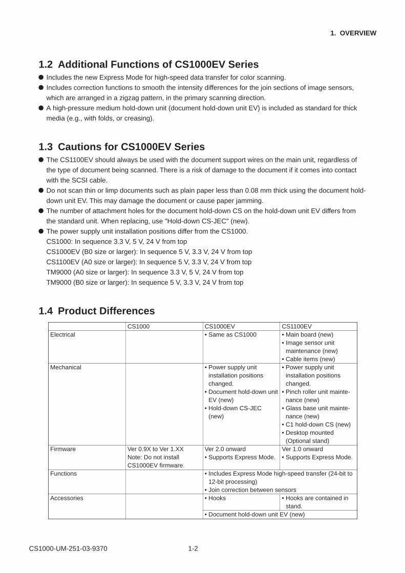
1.4 Product Differences
Electrical
Mechanical
Firmware
Functions
Accessories
CS1000
Ver 0.9X to Ver 1.XXNote: Do not installCS1000EV firmware.
CS1000EV• Same as CS1000
• Power supply unitinstallation positionschanged.
• Document hold-down unitEV (new)
• Hold-down CS-JEC(new)
Ver 2.0 onward• Supports Express Mode.
• Includes Express Mode high-speed transfer (24-bit to12-bit processing)
• Join correction between sensors• Hooks
• Document hold-down unit EV (new)
CS1100EV• Main board (new)• Image sensor unit
maintenance (new)• Cable items (new)• Power supply unit
installation positionschanged.
• Pinch roller unit mainte-nance (new)
• Glass base unit mainte-nance (new)
• C1 hold-down CS (new)• Desktop mounted
(Optional stand)Ver 1.0 onward• Supports Express Mode.
• Hooks are contained instand.
CS1000-UM-251-03-9370 1-3
1. OVERVIEW
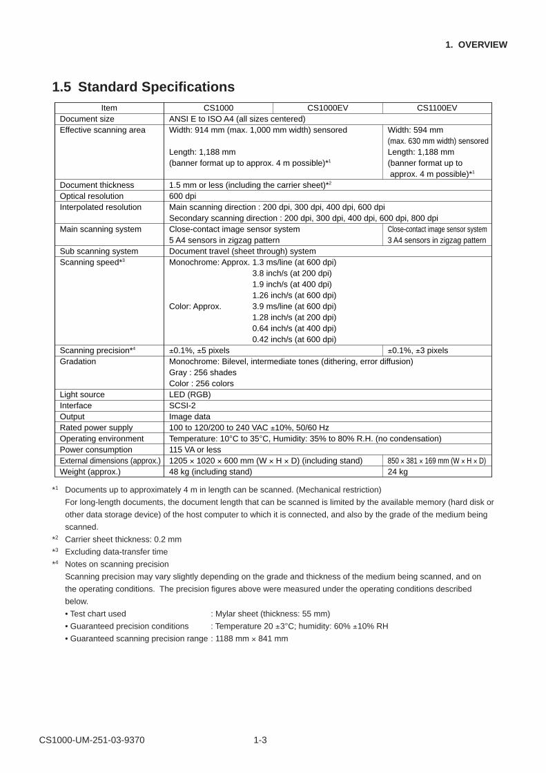
1.5 Standard SpecificationsItem CS1000 CS1000EV CS1100EV
Document size ANSI E to ISO A4 (all sizes centered)Effective scanning area Width: 914 mm (max. 1,000 mm width) sensored Width: 594 mm
(max. 630 mm width) sensoredLength: 1,188 mm Length: 1,188 mm(banner format up to approx. 4 m possible)*1 (banner format up to
approx. 4 m possible)*1
Document thickness 1.5 mm or less (including the carrier sheet)*2
Optical resolution 600 dpiInterpolated resolution Main scanning direction : 200 dpi, 300 dpi, 400 dpi, 600 dpi
Secondary scanning direction : 200 dpi, 300 dpi, 400 dpi, 600 dpi, 800 dpiMain scanning system Close-contact image sensor system Close-contact image sensor system
5 A4 sensors in zigzag pattern 3 A4 sensors in zigzag patternSub scanning system Document travel (sheet through) systemScanning speed*3 Monochrome: Approx. 1.3 ms/line (at 600 dpi)
3.8 inch/s (at 200 dpi)1.9 inch/s (at 400 dpi)1.26 inch/s (at 600 dpi)
Color: Approx. 3.9 ms/line (at 600 dpi)1.28 inch/s (at 200 dpi)0.64 inch/s (at 400 dpi)0.42 inch/s (at 600 dpi)
Scanning precision*4 ±0.1%, ±5 pixels ±0.1%, ±3 pixelsGradation Monochrome: Bilevel, intermediate tones (dithering, error diffusion)
Gray : 256 shadesColor : 256 colors
Light source LED (RGB)Interface SCSI-2Output Image dataRated power supply 100 to 120/200 to 240 VAC ±10%, 50/60 HzOperating environment Temperature: 10°C to 35°C, Humidity: 35% to 80% R.H. (no condensation)Power consumption 115 VA or lessExternal dimensions (approx.) 1205 × 1020 × 600 mm (W × H × D) (including stand) 850 × 381 × 169 mm (W × H × D)Weight (approx.) 48 kg (including stand) 24 kg
*1 Documents up to approximately 4 m in length can be scanned. (Mechanical restriction)
For long-length documents, the document length that can be scanned is limited by the available memory (hard disk or
other data storage device) of the host computer to which it is connected, and also by the grade of the medium being
scanned.
*2 Carrier sheet thickness: 0.2 mm
*3 Excluding data-transfer time
*4 Notes on scanning precision
Scanning precision may vary slightly depending on the grade and thickness of the medium being scanned, and on
the operating conditions. The precision figures above were measured under the operating conditions described
below.
• Test chart used : Mylar sheet (thickness: 55 mm)
• Guaranteed precision conditions : Temperature 20 ±3°C; humidity: 60% ±10% RH
• Guaranteed scanning precision range : 1188 mm × 841 mm
CS1000-UM-251-03-9370 1-4
1. OVERVIEW
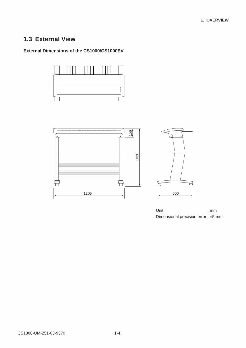
1.3 External View
External Dimensions of the CS1000/CS1000EV
156
1020
1205 600
Unit : mm
Dimensional precision error : ±5 mm
CS1000-UM-251-03-9370 1-5
1. OVERVIEW
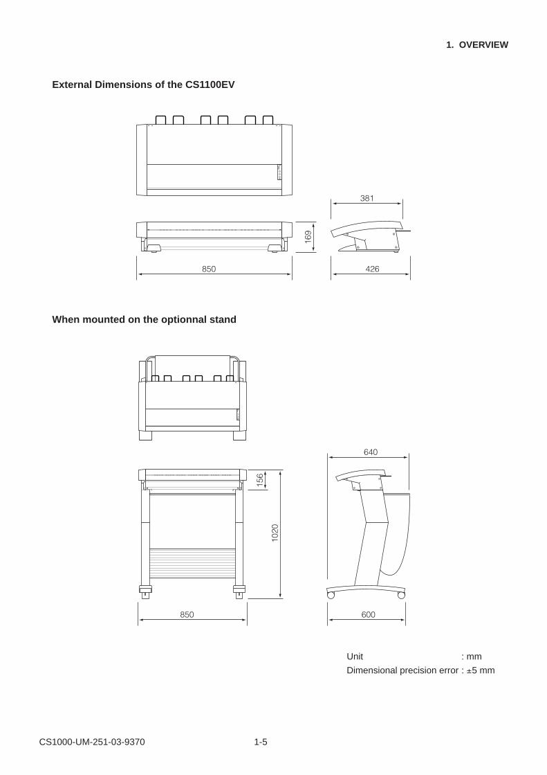
External Dimensions of the CS1100EV
169
850 426
381
When mounted on the optionnal stand
156
1020
850 600
640
Unit : mm
Dimensional precision error : ±5 mm
CS1000-UM-251-03-9370 1-6
1. OVERVIEW
1.4 System Requirements
The minimum system requirements for running the scanner’s hardware and software are listed below.
Operating system: Windows 95/98/Me, Windows NT 4.0, Windows 2000 or later
CPU: Pentium 133 MHz or higher
Memory: 32 MB or more
Monitor: 1024 × 768 pixels, 256 colors or more
Enough disk space to store data
Mouse
SCSI board by Adaptec
Recommended environment
For binary monochrome data CPU: Pentium 200 MHz or higher
Memory: 64 MB or more
SCSI board by Adaptec (PCI type)
For grayscale data CPU: Pentium III 550 MHz or higher
Memory: 256 MB or more
Monitor: 1024 × 768 pixels, High Color or higher resolution
SCSI board by Adaptec (PCI type)
For 8-bit color data CPU: Pentium III 866 MHz or higher
Memory: 512 MB or more
Monitor: 1024 × 768 pixels, True Color or higher
SCSI board by Adaptec (PCI type)
CHECKPOINT
The system configuration should correspond to the recommended specifications listed here, in order to ensure the
optimum capabilities of the scanner.
Use with a system configuration below the recommended specifications will affect the scanning speed and prevent
the scanner from operating to its specified capabilities.
To edit an A1-size or larger grayscale document with a resolution of 400 dpi or higher, or an 8-bit color document,
you may need more than the recommended memory sizes above. Depending on the type of document, you may not
be able to scan in the document even if you increase the memory size.
CS1000-UM-251-01-9370 2-1
2. PART NAMES AND FUNCTIONS
2. PART NAMES AND FUNCTIONS
2.1 Part Names and Functions
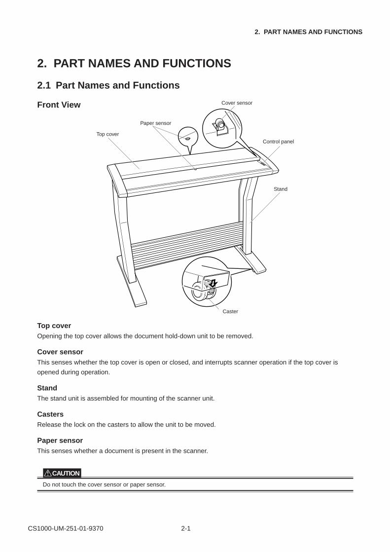
Front View Cover sensor
Paper sensor
Top cover
Caster
Control panel
Stand
Top coverOpening the top cover allows the document hold-down unit to be removed.
Cover sensorThis senses whether the top cover is open or closed, and interrupts scanner operation if the top cover is
opened during operation.
StandThe stand unit is assembled for mounting of the scanner unit.
CastersRelease the lock on the casters to allow the unit to be moved.
Paper sensorThis senses whether a document is present in the scanner.
CAUTION
Do not touch the cover sensor or paper sensor.
CS1000-UM-251-01-9370 2-2
2. PART NAMES AND FUNCTIONS
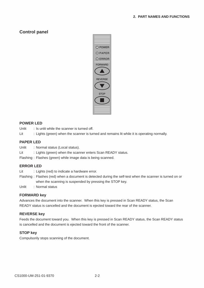
Control panel
POWER LEDUnlit : Is unlit while the scanner is turned off.
Lit : Lights (green) when the scanner is turned and remains lit while it is operating normally.
PAPER LEDUnlit : Normal status (Local status).
Lit : Lights (green) when the scanner enters Scan READY status.
Flashing : Flashes (green) while image data is being scanned.
ERROR LEDLit : Lights (red) to indicate a hardware error.
Flashing : Flashes (red) when a document is detected during the self-test when the scanner is turned on or
when the scanning is suspended by pressing the STOP key.
Unlit : Normal status
FORWARD keyAdvances the document into the scanner. When this key is pressed in Scan READY status, the Scan
READY status is cancelled and the document is ejected toward the rear of the scanner.
REVERSE keyFeeds the document toward you. When this key is pressed in Scan READY status, the Scan READY status
is cancelled and the document is ejected toward the front of the scanner.
STOP keyCompulsorily stops scanning of the document.
CS1000-UM-251-03-9370 2-3
2. PART NAMES AND FUNCTIONS
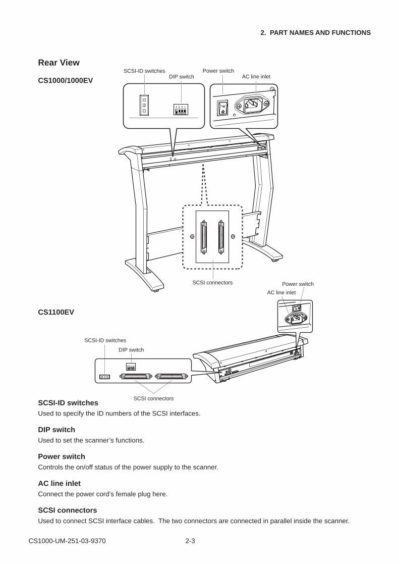
Rear View
CS1000/1000EV
SCSI-ID switchesDIP switch
Power switch AC line inlet
SCSI connectors
CS1100EV
4 3 2 1
SCSI-ID switches
DIP switch
AC line inlet
Power switch
SCSI connectorsSCSI-ID switchesUsed to specify the ID numbers of the SCSI interfaces.
DIP switchUsed to set the scanner’s functions.
Power switchControls the on/off status of the power supply to the scanner.
AC line inletConnect the power cord’s female plug here.
SCSI connectorsUsed to connect SCSI interface cables. The two connectors are connected in parallel inside the scanner.
CS1000-UM-251-01-9370 2-4
2. PART NAMES AND FUNCTIONS
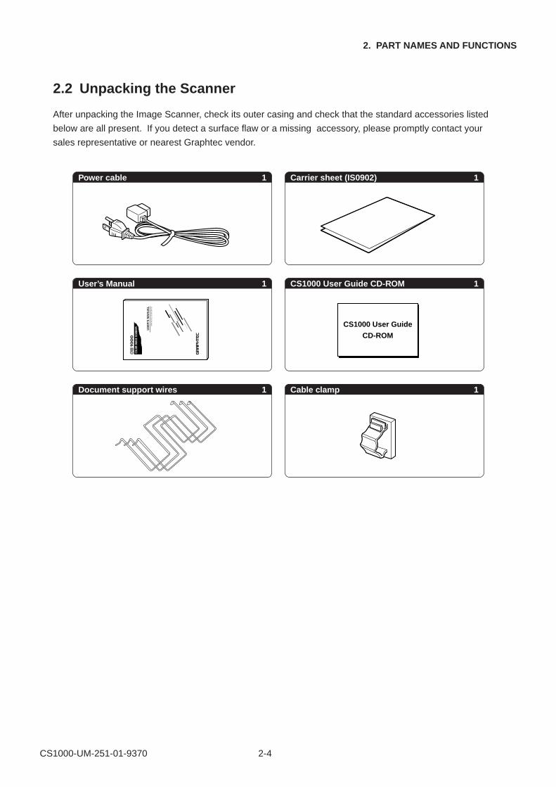
2.2 Unpacking the Scanner
After unpacking the Image Scanner, check its outer casing and check that the standard accessories listed
below are all present. If you detect a surface flaw or a missing accessory, please promptly contact your
sales representative or nearest Graphtec vendor.
Power cable 1 Carrier sheet (IS0902)
User’s Manual CS1000 User Guide CD-ROM
Document support wires Cable clamp
CS1000 User Guide
CD-ROM
1
1 1
1 1
CS1000-UM-251-01-9370 3-1
3. PREPARING TO OPERATE THE SCANNER
3. PREPARING TO OPERATE THE SCANNER
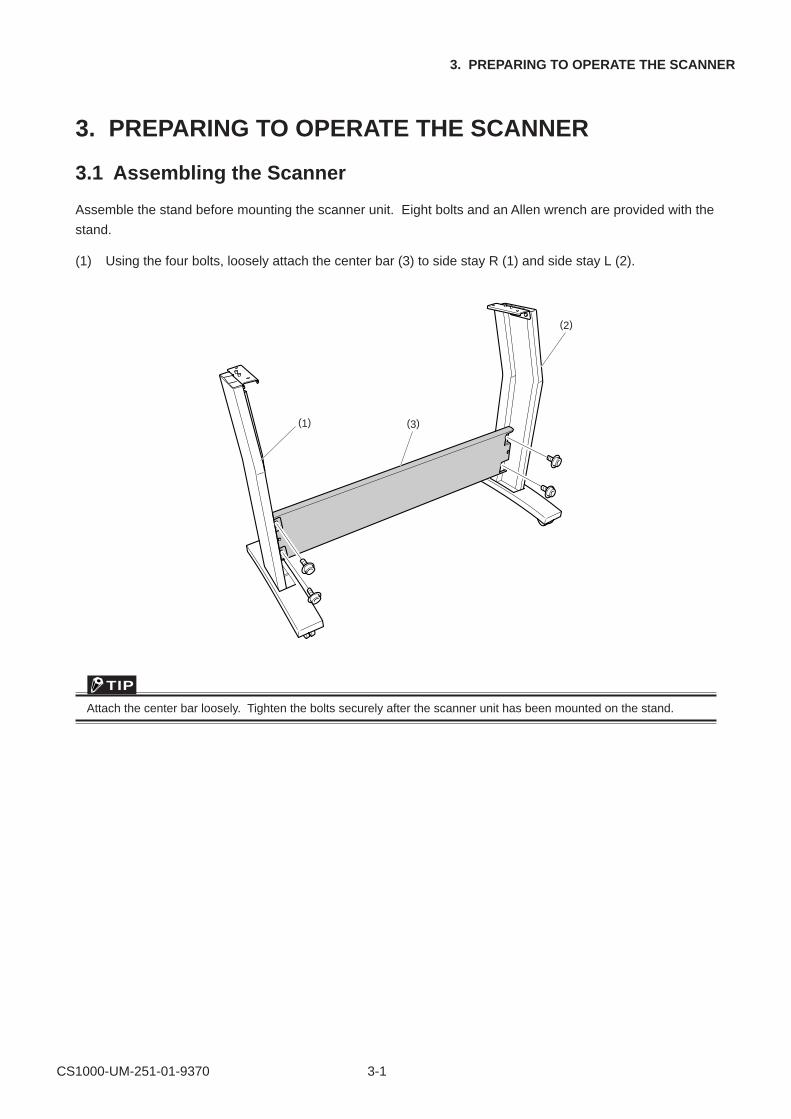
3.1 Assembling the Scanner
Assemble the stand before mounting the scanner unit. Eight bolts and an Allen wrench are provided with the
stand.
(1) Using the four bolts, loosely attach the center bar (3) to side stay R (1) and side stay L (2).
(1)
(2)
(3)
TIP
Attach the center bar loosely. Tighten the bolts securely after the scanner unit has been mounted on the stand.
CS1000-UM-251-01-9370 3-2
3. PREPARING TO OPERATE THE SCANNER
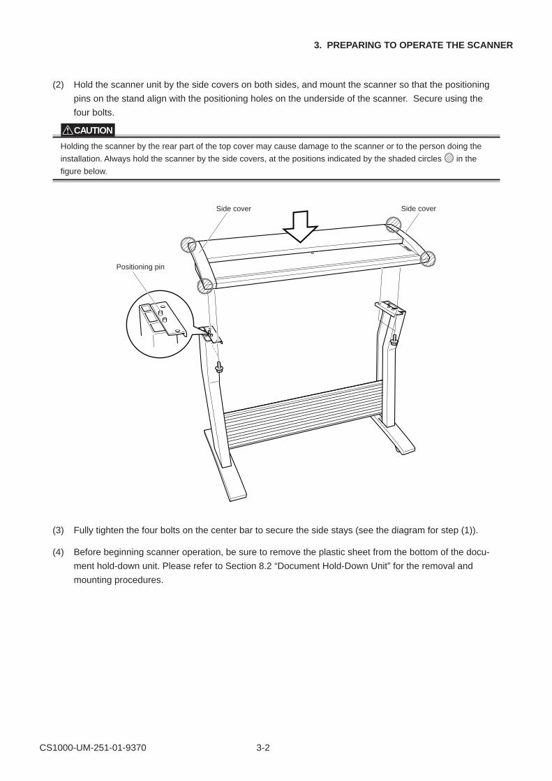
(2) Hold the scanner unit by the side covers on both sides, and mount the scanner so that the positioning
pins on the stand align with the positioning holes on the underside of the scanner. Secure using the
four bolts.
CAUTION
Holding the scanner by the rear part of the top cover may cause damage to the scanner or to the person doing the
installation. Always hold the scanner by the side covers, at the positions indicated by the shaded circles in the
figure below.
Positioning pin
Side coverSide cover
(3) Fully tighten the four bolts on the center bar to secure the side stays (see the diagram for step (1)).
(4) Before beginning scanner operation, be sure to remove the plastic sheet from the bottom of the docu-
ment hold-down unit. Please refer to Section 8.2 “Document Hold-Down Unit” for the removal and
mounting procedures.
CS1000-UM-251-01-9370 3-3
3. PREPARING TO OPERATE THE SCANNER
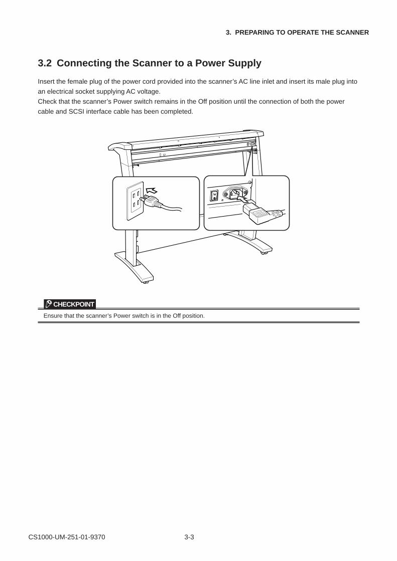
3.2 Connecting the Scanner to a Power Supply
Insert the female plug of the power cord provided into the scanner’s AC line inlet and insert its male plug into
an electrical socket supplying AC voltage.
Check that the scanner’s Power switch remains in the Off position until the connection of both the power
cable and SCSI interface cable has been completed.
CHECKPOINT
Ensure that the scanner’s Power switch is in the Off position.
CS1000-UM-251-01-9370 3-4
3. PREPARING TO OPERATE THE SCANNER
3.3 Connecting the SCSI Cable
Obtain a SCSI interface cable (optional) that is compatible with the computer to be connected.
Compatible CablesThe cable must have half-pitch pin-type 50-pin connectors.
To connect multiple SCSI devices in a daisy-chain* arrangement, the total cable length must be no longer
than three meters.
Among Graphtec cables, the SC0006 or SC0006 2M model can be used (depending on the shape of the
connector on the computer’s SCSI interface board).
TIP
* Daisy-chain: A method for connecting peripheral devices in a ring arrangement
CAUTION
The use of an incompatible cable may cause the scanner to malfunction or damage the interface.
If the cable comes into contact with the document, use the cable clamp provided as a standard accessory to fasten
the cable to the underside of the scanner.
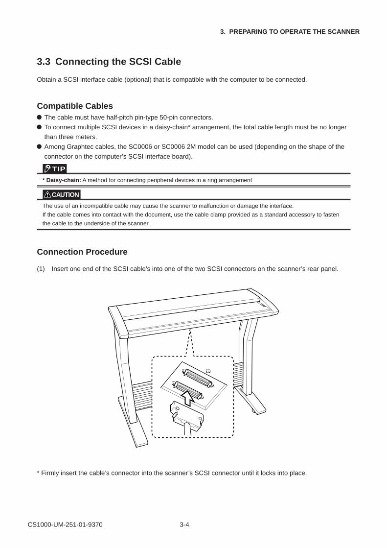
Connection Procedure
(1) Insert one end of the SCSI cable’s into one of the two SCSI connectors on the scanner’s rear panel.
* Firmly insert the cable’s connector into the scanner’s SCSI connector until it locks into place.
CS1000-UM-251-01-9370 3-5
3. PREPARING TO OPERATE THE SCANNER
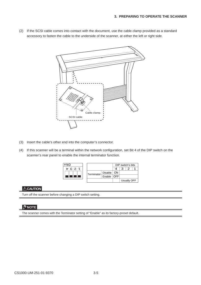
(2) If the SCSI cable comes into contact with the document, use the cable clamp provided as a standard
accessory to fasten the cable to the underside of the scanner, at either the left or right side.
SCSI cable
Cable clamp
(3) Insert the cable’s other end into the computer’s connector.
(4) If this scanner will be a terminal within the network configuration, set Bit 4 of the DIP switch on the
scanner’s rear panel to enable the internal terminator function.
1 2 3 4
4 3 2 1
ON
DIP switch’s bits
ONOFF
Usually OFF
TerminatorDisableEnable
CAUTION
Turn off the scanner before changing a DIP switch setting.
NOTE
The scanner comes with the Terminator setting of “Enable” as its factory-preset default.
CS1000-UM-251-01-9370 3-6
3. PREPARING TO OPERATE THE SCANNER
3.4 Setting the ID Number
The SCSI bus is designed to allow up to eight devices to be connected at the same time. As a result, a
single computer can be used to exchange data with multiple SCSI devices, including a scanner and disk
drives. Each device must be assigned an ID number (device number) to enable the devices to be distin-
guished on the SCSI bus.
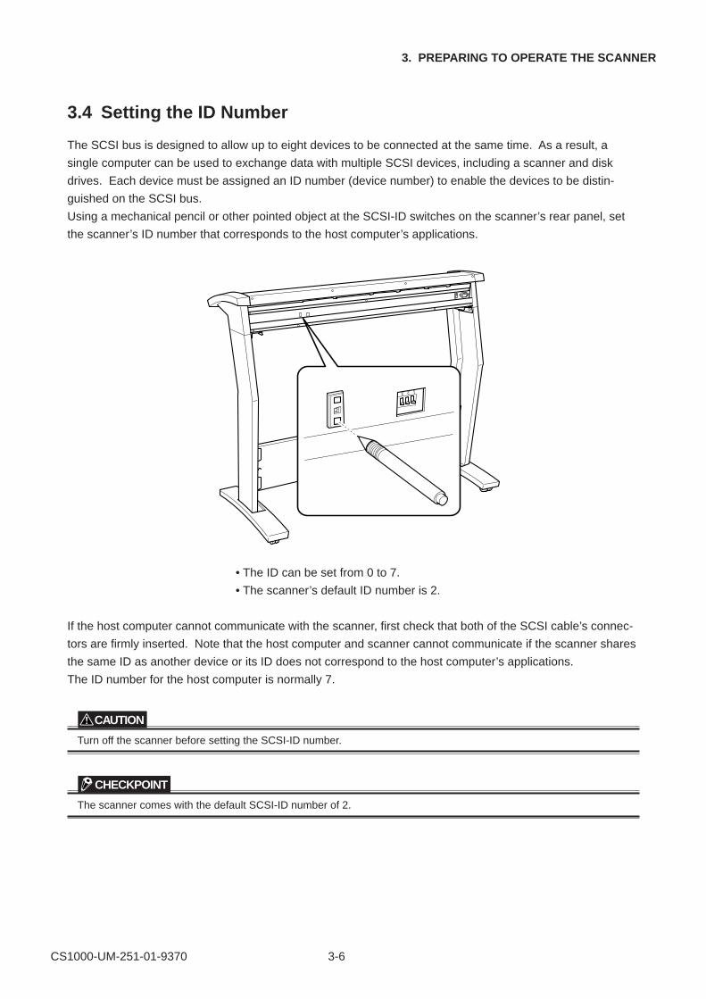
Using a mechanical pencil or other pointed object at the SCSI-ID switches on the scanner’s rear panel, set
the scanner’s ID number that corresponds to the host computer’s applications.
2
3 2 1
• The ID can be set from 0 to 7.
• The scanner’s default ID number is 2.
If the host computer cannot communicate with the scanner, first check that both of the SCSI cable’s connec-
tors are firmly inserted. Note that the host computer and scanner cannot communicate if the scanner shares
the same ID as another device or its ID does not correspond to the host computer’s applications.
The ID number for the host computer is normally 7.
CAUTION
Turn off the scanner before setting the SCSI-ID number.
CHECKPOINT
The scanner comes with the default SCSI-ID number of 2.
CS1000-UM-251-01-9370 3-7
3. PREPARING TO OPERATE THE SCANNER
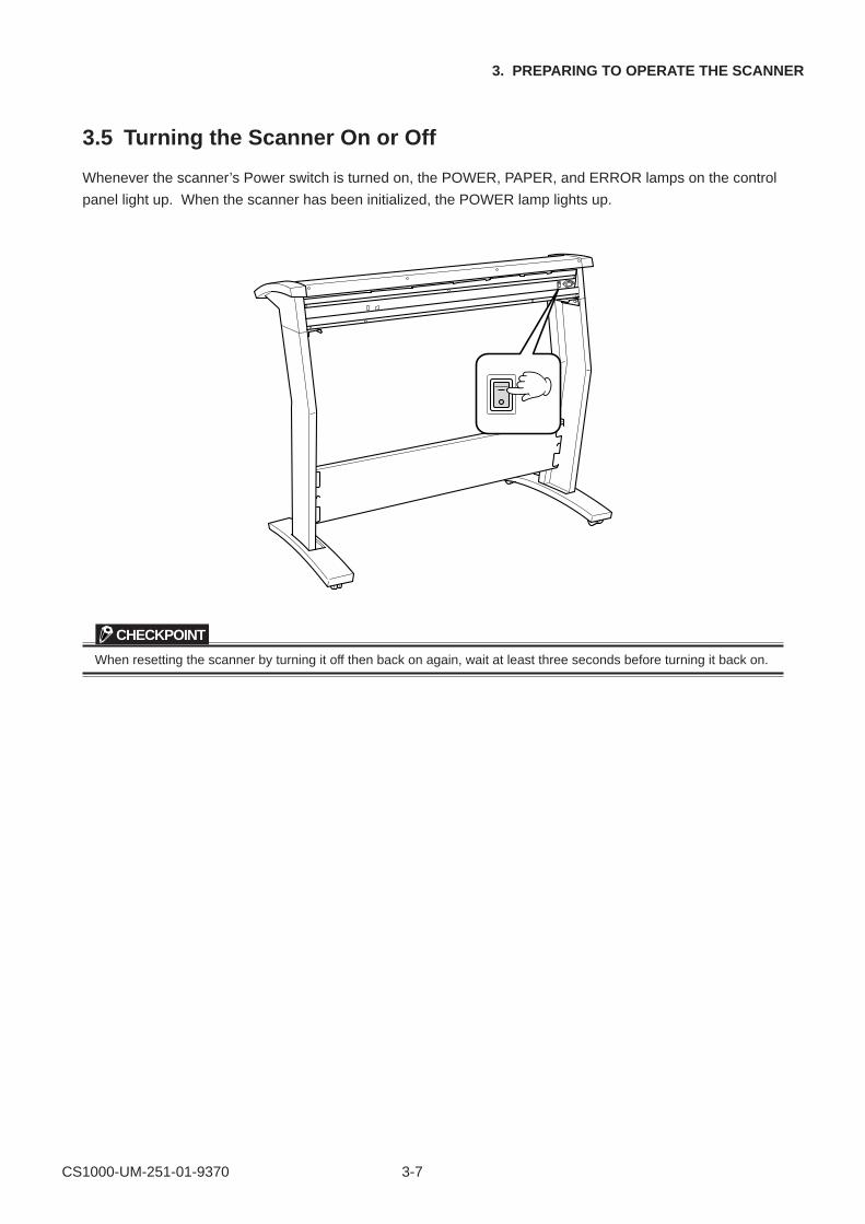
3.5 Turning the Scanner On or Off
Whenever the scanner’s Power switch is turned on, the POWER, PAPER, and ERROR lamps on the control
panel light up. When the scanner has been initialized, the POWER lamp lights up.
CHECKPOINT
When resetting the scanner by turning it off then back on again, wait at least three seconds before turning it back on.
CS1000-UM-251-03-9370 3-8
3. PREPARING TO OPERATE THE SCANNER
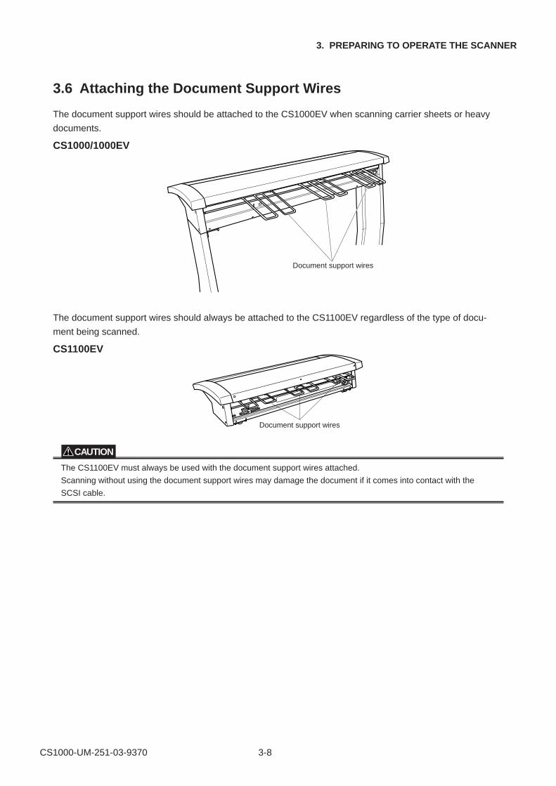
3.6 Attaching the Document Support Wires
The document support wires should be attached to the CS1000EV when scanning carrier sheets or heavy
documents.
CS1000/1000EV
Document support wires
The document support wires should always be attached to the CS1100EV regardless of the type of docu-
ment being scanned.
CS1100EV
Document support wires
CAUTION
The CS1100EV must always be used with the document support wires attached.
Scanning without using the document support wires may damage the document if it comes into contact with the
SCSI cable.
CS1000-UM-251-03-9370 3-9
3. PREPARING TO OPERATE THE SCANNER
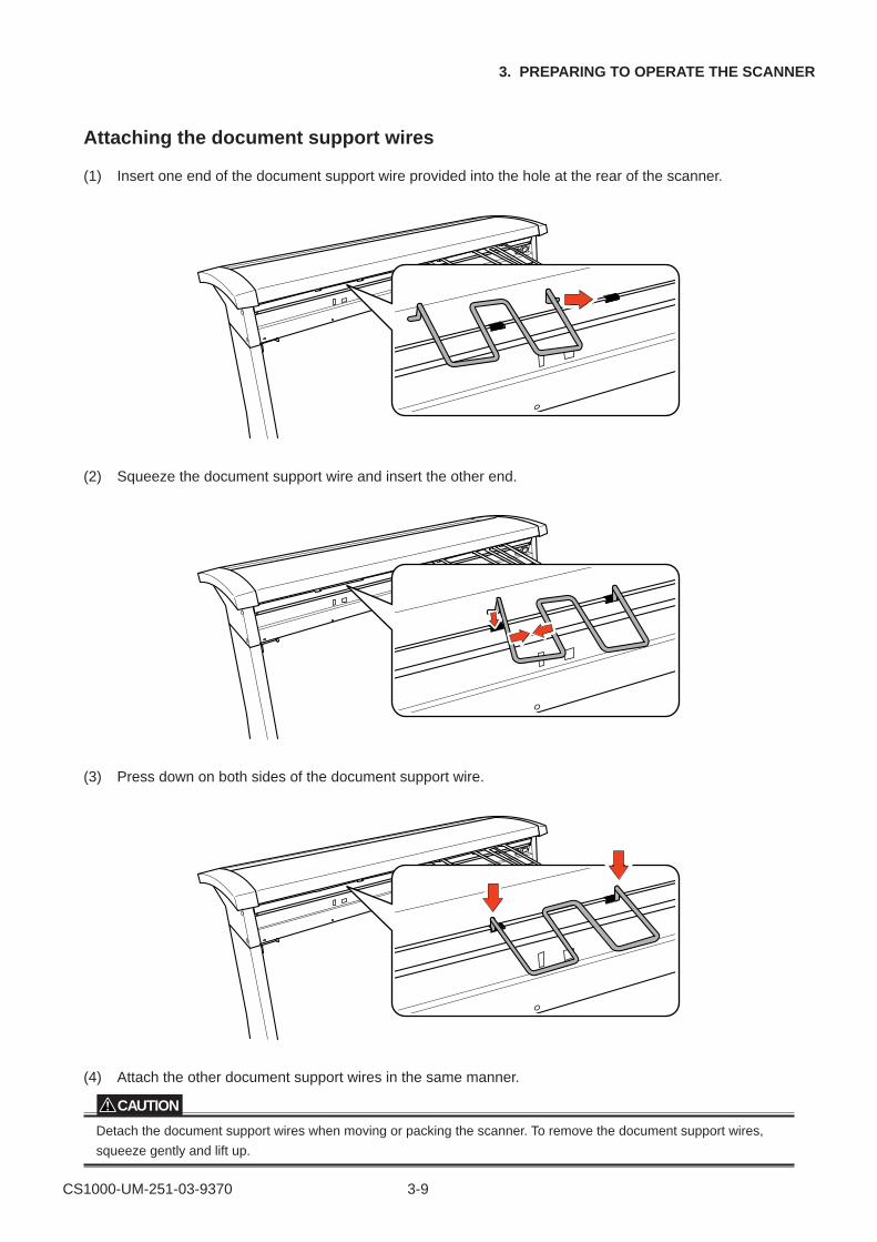
Attaching the document support wires
(1) Insert one end of the document support wire provided into the hole at the rear of the scanner.
(2) Squeeze the document support wire and insert the other end.
(3) Press down on both sides of the document support wire.
(4) Attach the other document support wires in the same manner.
CAUTION
Detach the document support wires when moving or packing the scanner. To remove the document support wires,
squeeze gently and lift up.
CS1000-UM-251-03-9370 3-10
3. PREPARING TO OPERATE THE SCANNER
3.7 Document Hold-down Unit EV
The document hold-down unit EV should be used according to the type of documents being scanned.
The document hold-down unit EV is normally stored on the center bar of the stand and should be used in
place of the standard document hold-down unit when required.
The document hold-down unit EV should be used for the following types of documents.
Plain paper more than 0.08 mm thick with prominent folds or curling that is likely to affect scanning quality.
CAUTION
Do not use the document hold-down unit EV when scanning thin or limp documents such as plain paper less than
0.08 mm thick. This may result in damage to the document and paper jamming.
The document hold-down unit EV uses a greater document restraining force than the standard document hold-down
unit. Some types of documents may be more susceptible to damage.
Use a carrier sheet when scanning film.
The scanning precision is different from that using the standard document hold-down unit, and so distance correction
may be necessary.
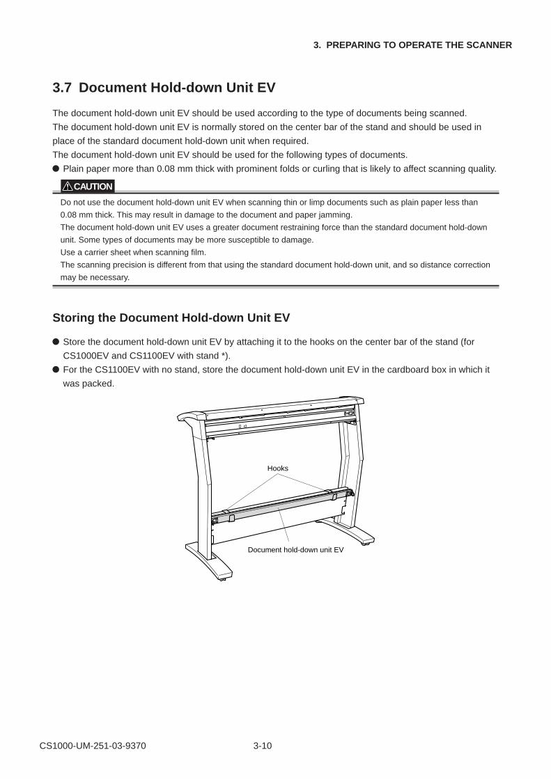
Storing the Document Hold-down Unit EV
Store the document hold-down unit EV by attaching it to the hooks on the center bar of the stand (for
CS1000EV and CS1100EV with stand *).
For the CS1100EV with no stand, store the document hold-down unit EV in the cardboard box in which it
was packed.
Hooks
Document hold-down unit EV
CS1000-UM-251-03-9370 3-11
3. PREPARING TO OPERATE THE SCANNER
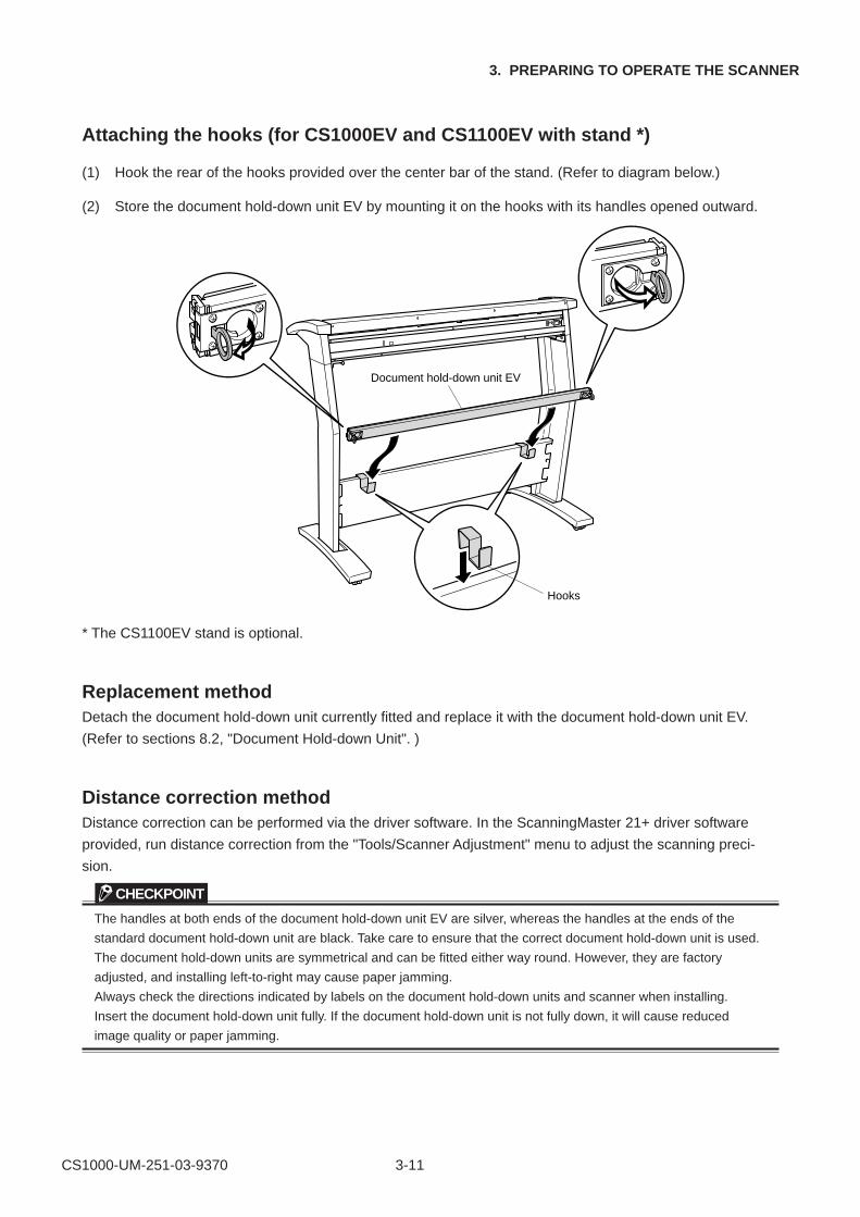
Attaching the hooks (for CS1000EV and CS1100EV with stand *)
(1) Hook the rear of the hooks provided over the center bar of the stand. (Refer to diagram below.)
(2) Store the document hold-down unit EV by mounting it on the hooks with its handles opened outward.
Hooks
Document hold-down unit EV
* The CS1100EV stand is optional.
Replacement methodDetach the document hold-down unit currently fitted and replace it with the document hold-down unit EV.
(Refer to sections 8.2, "Document Hold-down Unit". )
Distance correction methodDistance correction can be performed via the driver software. In the ScanningMaster 21+ driver software
provided, run distance correction from the "Tools/Scanner Adjustment" menu to adjust the scanning preci-
sion.
CHECKPOINT
The handles at both ends of the document hold-down unit EV are silver, whereas the handles at the ends of the
standard document hold-down unit are black. Take care to ensure that the correct document hold-down unit is used.
The document hold-down units are symmetrical and can be fitted either way round. However, they are factory
adjusted, and installing left-to-right may cause paper jamming.
Always check the directions indicated by labels on the document hold-down units and scanner when installing.
Insert the document hold-down unit fully. If the document hold-down unit is not fully down, it will cause reduced
image quality or paper jamming.
CS1000-UM-251-01-9370 4-1
4. OPERATION AND CONNECTION
4. OPERATION AND CONNECTION
4.1 Connecting the Scanner to a Computer
Before you can start connecting the scanner to the computer, you need to prepare (confirm) the computer
system’s environment.
(1) Confirm that the computer’s operating system has been properly installed.
(2) Confirm that a SCSI adapter has been connected to the computer.
(3) Confirm that the SCSI driver has been installed in the computer.
Connecting the CS1000 to a Computer for the First Time
For Windows 95 or Windows 95 Version a:
(1) After checking that the scanner and the computer are properly connected via the SCSI interface cable,
turn on the scanner first and then turn on the computer.
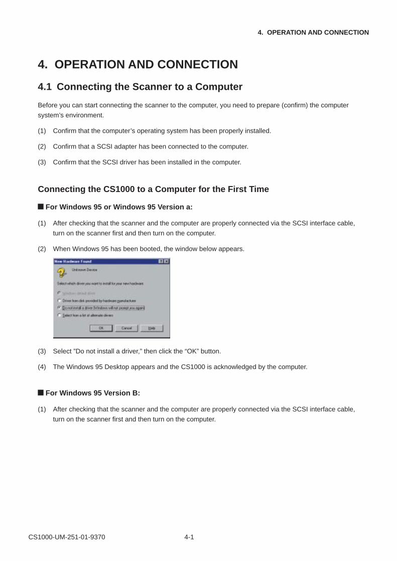
(2) When Windows 95 has been booted, the window below appears.
(3) Select ”Do not install a driver,” then click the “OK” button.
(4) The Windows 95 Desktop appears and the CS1000 is acknowledged by the computer.
For Windows 95 Version B:
(1) After checking that the scanner and the computer are properly connected via the SCSI interface cable,
turn on the scanner first and then turn on the computer.
CS1000-UM-251-01-9370 4-2
4. OPERATION AND CONNECTION
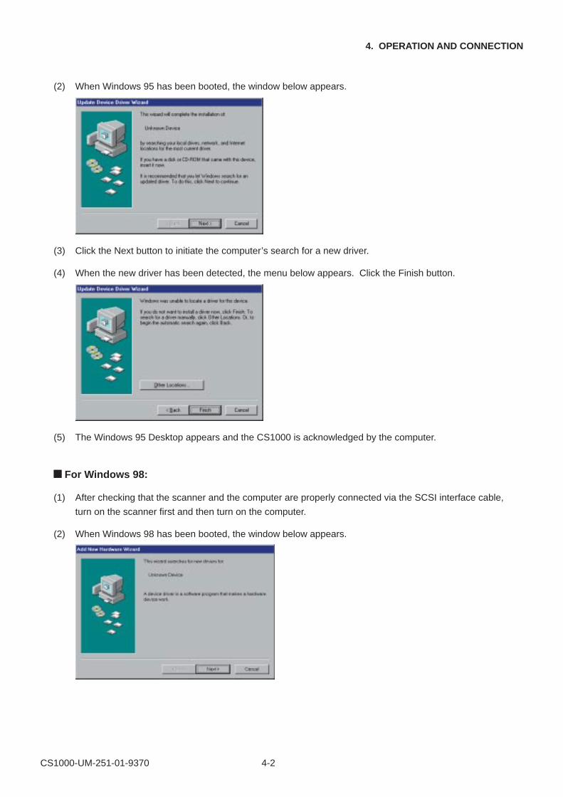
(2) When Windows 95 has been booted, the window below appears.
(3) Click the Next button to initiate the computer’s search for a new driver.
(4) When the new driver has been detected, the menu below appears. Click the Finish button.
(5) The Windows 95 Desktop appears and the CS1000 is acknowledged by the computer.
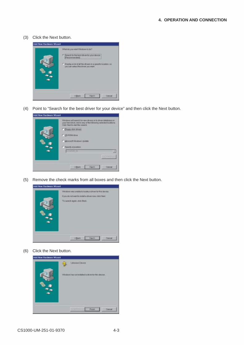
For Windows 98:
(1) After checking that the scanner and the computer are properly connected via the SCSI interface cable,
turn on the scanner first and then turn on the computer.
(2) When Windows 98 has been booted, the window below appears.
CS1000-UM-251-01-9370 4-3
4. OPERATION AND CONNECTION
(3) Click the Next button.
(4) Point to “Search for the best driver for your device” and then click the Next button.
(5) Remove the check marks from all boxes and then click the Next button.
(6) Click the Next button.
CS1000-UM-251-01-9370 4-4
4. OPERATION AND CONNECTION
(7) Click the Finish button.
(8) The Windows 98 Desktop appears and the CS1000 is acknowledged by the computer.
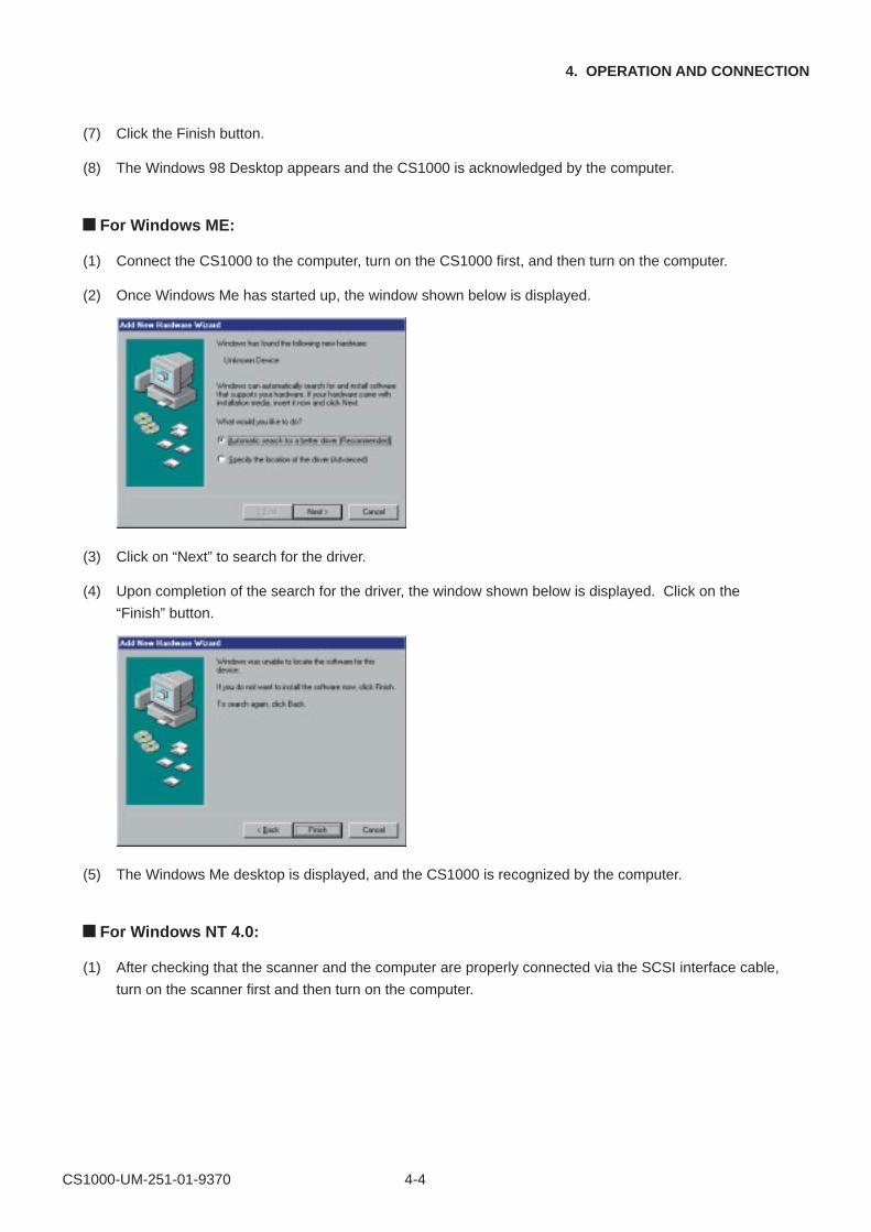
For Windows ME:
(1) Connect the CS1000 to the computer, turn on the CS1000 first, and then turn on the computer.
(2) Once Windows Me has started up, the window shown below is displayed.
(3) Click on “Next” to search for the driver.
(4) Upon completion of the search for the driver, the window shown below is displayed. Click on the
“Finish” button.
(5) The Windows Me desktop is displayed, and the CS1000 is recognized by the computer.
For Windows NT 4.0:
(1) After checking that the scanner and the computer are properly connected via the SCSI interface cable,
turn on the scanner first and then turn on the computer.
CS1000-UM-251-01-9370 4-5
4. OPERATION AND CONNECTION
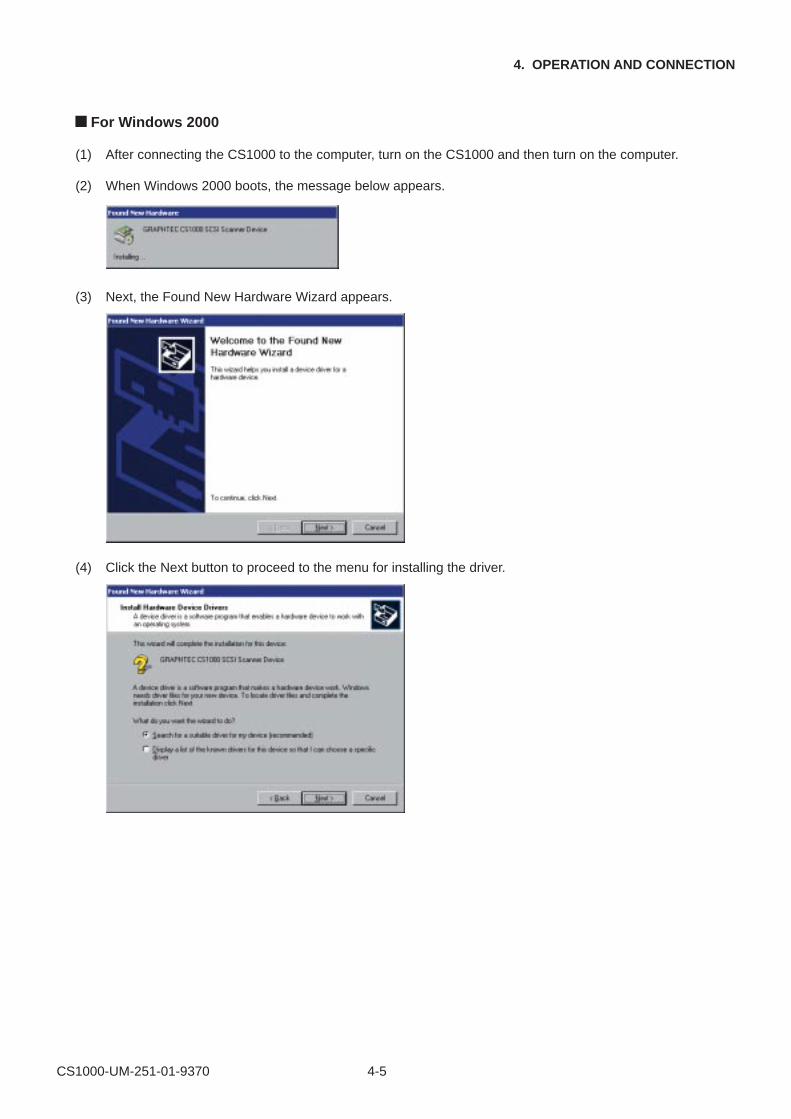
For Windows 2000
(1) After connecting the CS1000 to the computer, turn on the CS1000 and then turn on the computer.
(2) When Windows 2000 boots, the message below appears.
(3) Next, the Found New Hardware Wizard appears.
(4) Click the Next button to proceed to the menu for installing the driver.
CS1000-UM-251-01-9370 4-6
4. OPERATION AND CONNECTION
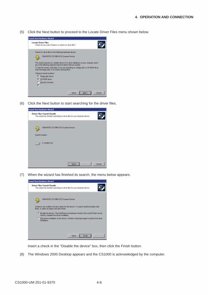
(5) Click the Next button to proceed to the Locate Driver Files menu shown below.
(6) Click the Next button to start searching for the driver files.
(7) When the wizard has finished its search, the menu below appears.
Insert a check in the “Disable the device” box, then click the Finish button.
(8) The Windows 2000 Desktop appears and the CS1000 is acknowledged by the computer.
CS1000-UM-251-01-9370 4-7
4. OPERATION AND CONNECTION
4.2 Checking the Interface Connection
CHECKPOINT
If the scanner is connected to a system with Adaptec EZ-SCSI DELUXE* installed, the scanner will be recognized
under “Scanner” in the Device Manager.
* EZ-SCSI DELUXE is the software included with the SCSI adapter. For details, see the SCSI adapter instruction
manual.
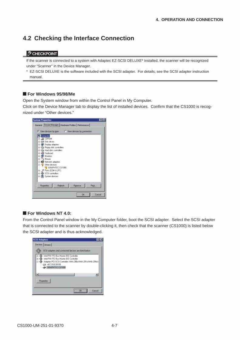
For Windows 95/98/MeOpen the System window from within the Control Panel in My Computer.
Click on the Device Manager tab to display the list of installed devices. Confirm that the CS1000 is recog-
nized under “Other devices.”
For Windows NT 4.0:From the Control Panel window in the My Computer folder, boot the SCSI adapter. Select the SCSI adapter
that is connected to the scanner by double-clicking it, then check that the scanner (CS1000) is listed below
the SCSI adapter and is thus acknowledged.
CS1000-UM-251-01-9370 4-8
4. OPERATION AND CONNECTION
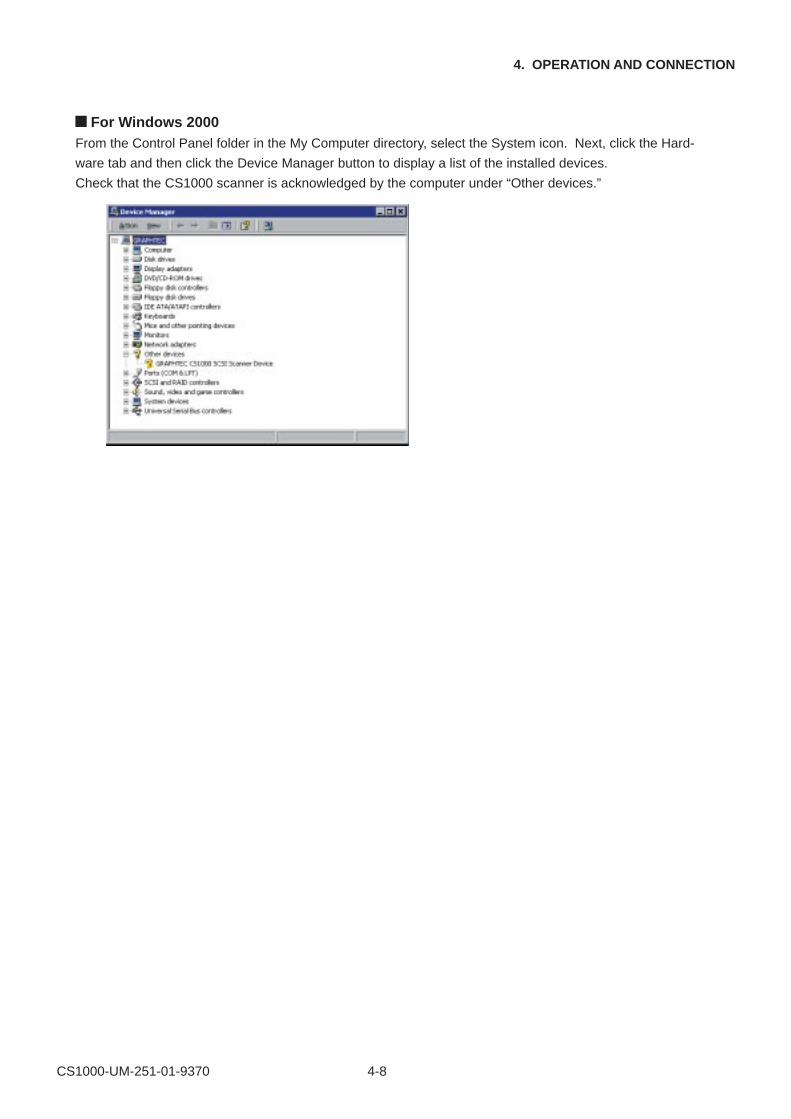
For Windows 2000From the Control Panel folder in the My Computer directory, select the System icon. Next, click the Hard-
ware tab and then click the Device Manager button to display a list of the installed devices.
Check that the CS1000 scanner is acknowledged by the computer under “Other devices.”
CS1000-UM-251-01-9370 4-9
4. OPERATION AND CONNECTION
4.3 Installing the Scanning Master 21+ Application
The Scanning Master 21+ “OPS112” is a software application for using a Graphtec scanner to scan image
data. The OPS112 User’s Manual is contained in the file name “OPS112-1.pdf”.
Operating Environment
Windows 95/Windows 98/Windows Me, Windows NT 4.0, or Windows 2000.
Installation Procedure(The following steps are explained using the Windows 95 windows.)
(1) Boot Windows 95.
(2) Insert the CS1000 User Guide CD-ROM containing the OPS112 program files into the computer’s CD-
ROM drive.
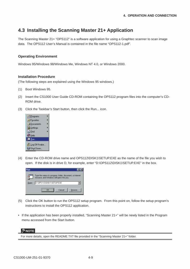
(3) Click the Taskbar’s Start button, then click the Run... icon.
(4) Enter the CD-ROM drive name and OPS112\DISK1\SETUP.EXE as the name of the file you wish to
open. If the disk is in drive D, for example, enter “D:\OPS112\DISK1\SETUP.EXE” in the box.
(5) Click the OK button to run the OPS112 setup program. From this point on, follow the setup program’s
instructions to install the OPS112 application.
• If the application has been properly installed, “Scanning Master 21+” will be newly listed in the Program
menu accessed from the Start button.
NOTE
For more details, open the README.TXT file provided in the “Scanning Master 21+” folder.
CS1000-UM-251-01-9370 4-10
4. OPERATION AND CONNECTION
4.4 Installing the Scanning Master Copy Color Application
The Scanning Master Copy Color “OPS116” is a software application for outputting image data scanned in by
a Graphtec scanner to a plotter or printer.
Operating EnvironmentWindows 95/Windows 98/Windows Me, Windows NT 4.0, or Windows 2000.
Installation Procedure(The following steps are explained using the Windows 95 windows.)
(1) Boot Windows 95.
(2) Insert the CS1000 User Guide CD-ROM containing the OPS116 program files into the computer’s CD-
ROM drive.
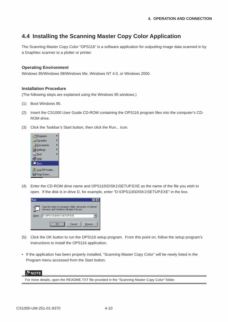
(3) Click the Taskbar’s Start button, then click the Run... icon.
(4) Enter the CD-ROM drive name and OPS116\DISK1\SETUP.EXE as the name of the file you wish to
open. If the disk is in drive D, for example, enter “D:\OPS116\DISK1\SETUP.EXE” in the box.
(5) Click the OK button to run the OPS116 setup program. From this point on, follow the setup program’s
instructions to install the OPS116 application.
• If the application has been properly installed, “Scanning Master Copy Color” will be newly listed in the
Program menu accessed from the Start button.
NOTE
For more details, open the README.TXT file provided in the “Scanning Master Copy Color” folder.
CS1000-UM-251-01-9370 4-11
4. OPERATION AND CONNECTION
4.5 Document Types Compatible with the CS1000
Because the CS1000 scans a document while feeding it, the document types that it can scan are subject to
the following restrictions.
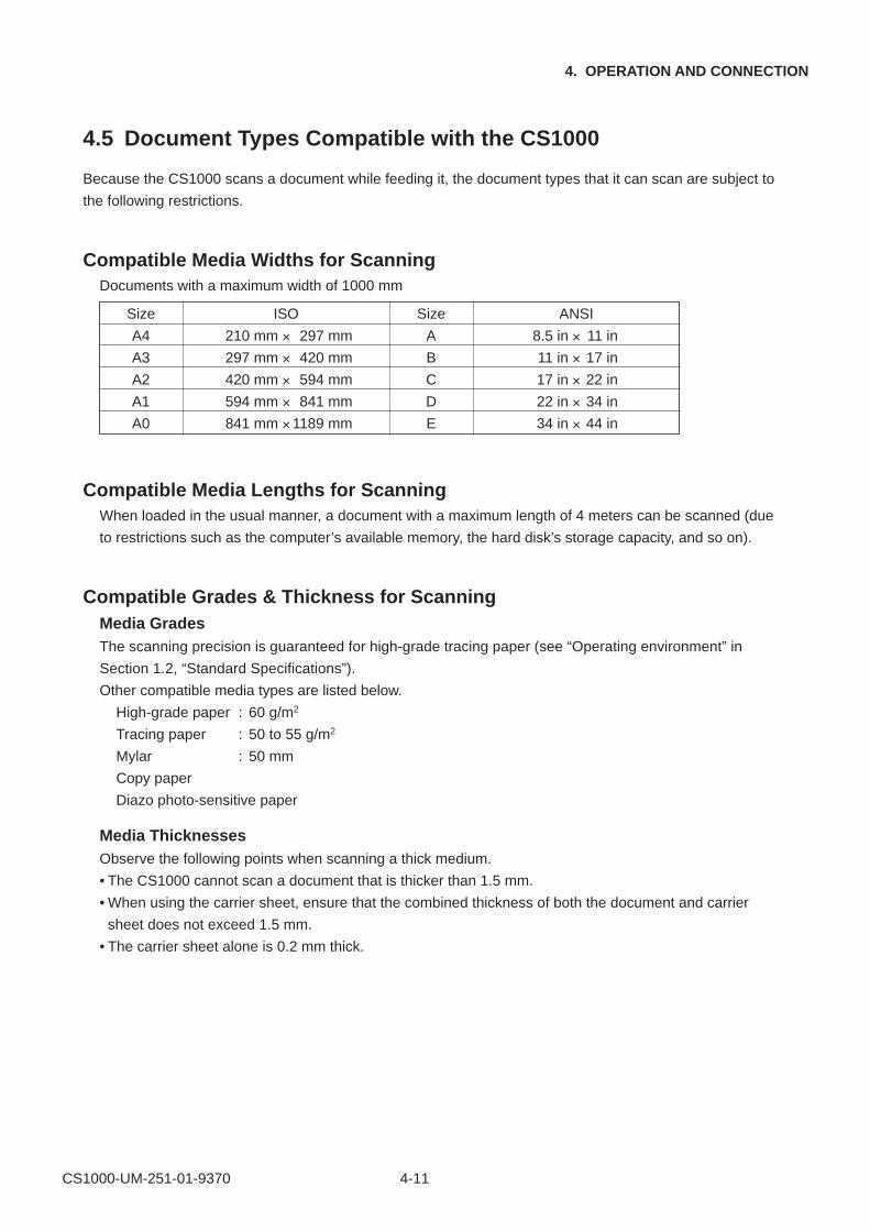
Compatible Media Widths for ScanningDocuments with a maximum width of 1000 mm
Compatible Media Lengths for ScanningWhen loaded in the usual manner, a document with a maximum length of 4 meters can be scanned (due
to restrictions such as the computer’s available memory, the hard disk’s storage capacity, and so on).
Compatible Grades & Thickness for ScanningMedia GradesThe scanning precision is guaranteed for high-grade tracing paper (see “Operating environment” in
Section 1.2, “Standard Specifications”).
Other compatible media types are listed below.
High-grade paper : 60 g/m2
Tracing paper : 50 to 55 g/m2
Mylar : 50 mm
Copy paper
Diazo photo-sensitive paper
Media ThicknessesObserve the following points when scanning a thick medium.
• The CS1000 cannot scan a document that is thicker than 1.5 mm.
• When using the carrier sheet, ensure that the combined thickness of both the document and carrier
sheet does not exceed 1.5 mm.
• The carrier sheet alone is 0.2 mm thick.
Size ISO Size ANSI
A4 210 mm × 297 mm A 8.5 in × 11 in
A3 297 mm × 420 mm B 11 in × 17 in
A2 420 mm × 594 mm C 17 in × 22 in
A1 594 mm × 841 mm D 22 in × 34 in
A0 841 mm ×1189 mm E 34 in × 44 in
CS1000-UM-251-01-9370 4-12
4. OPERATION AND CONNECTION
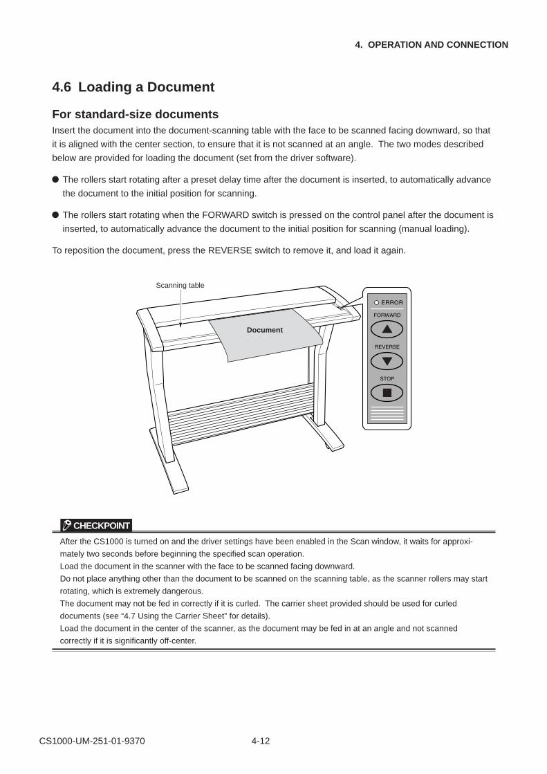
4.6 Loading a Document
For standard-size documentsInsert the document into the document-scanning table with the face to be scanned facing downward, so that
it is aligned with the center section, to ensure that it is not scanned at an angle. The two modes described
below are provided for loading the document (set from the driver software).
The rollers start rotating after a preset delay time after the document is inserted, to automatically advance
the document to the initial position for scanning.
The rollers start rotating when the FORWARD switch is pressed on the control panel after the document is
inserted, to automatically advance the document to the initial position for scanning (manual loading).
To reposition the document, press the REVERSE switch to remove it, and load it again.
Scanning table
Document
CHECKPOINT
After the CS1000 is turned on and the driver settings have been enabled in the Scan window, it waits for approxi-
mately two seconds before beginning the specified scan operation.
Load the document in the scanner with the face to be scanned facing downward.
Do not place anything other than the document to be scanned on the scanning table, as the scanner rollers may start
rotating, which is extremely dangerous.
The document may not be fed in correctly if it is curled. The carrier sheet provided should be used for curled
documents (see “4.7 Using the Carrier Sheet” for details).
Load the document in the center of the scanner, as the document may be fed in at an angle and not scanned
correctly if it is significantly off-center.
CS1000-UM-251-01-9370 4-13
4. OPERATION AND CONNECTION
4.7 Using the Carrier Sheet
Use the carrier sheet according to the condition of the document to be scanned.
In the case of scanning the following types of media, always place the document on the carrier sheet before
loading it into the scanner.
To scan a medium that is as limp as or limper than a newspaper
To scan paper that is badly curled
To scan a document that is smaller than A4 size or a document of non-standard size
To scan a medium that tears easily
When the target document cannot be properly advanced to the initial position of scanning (because the
target document is folded, wrinkled, or otherwise hard to load in the scanner)
To scan transparent or translucent documents
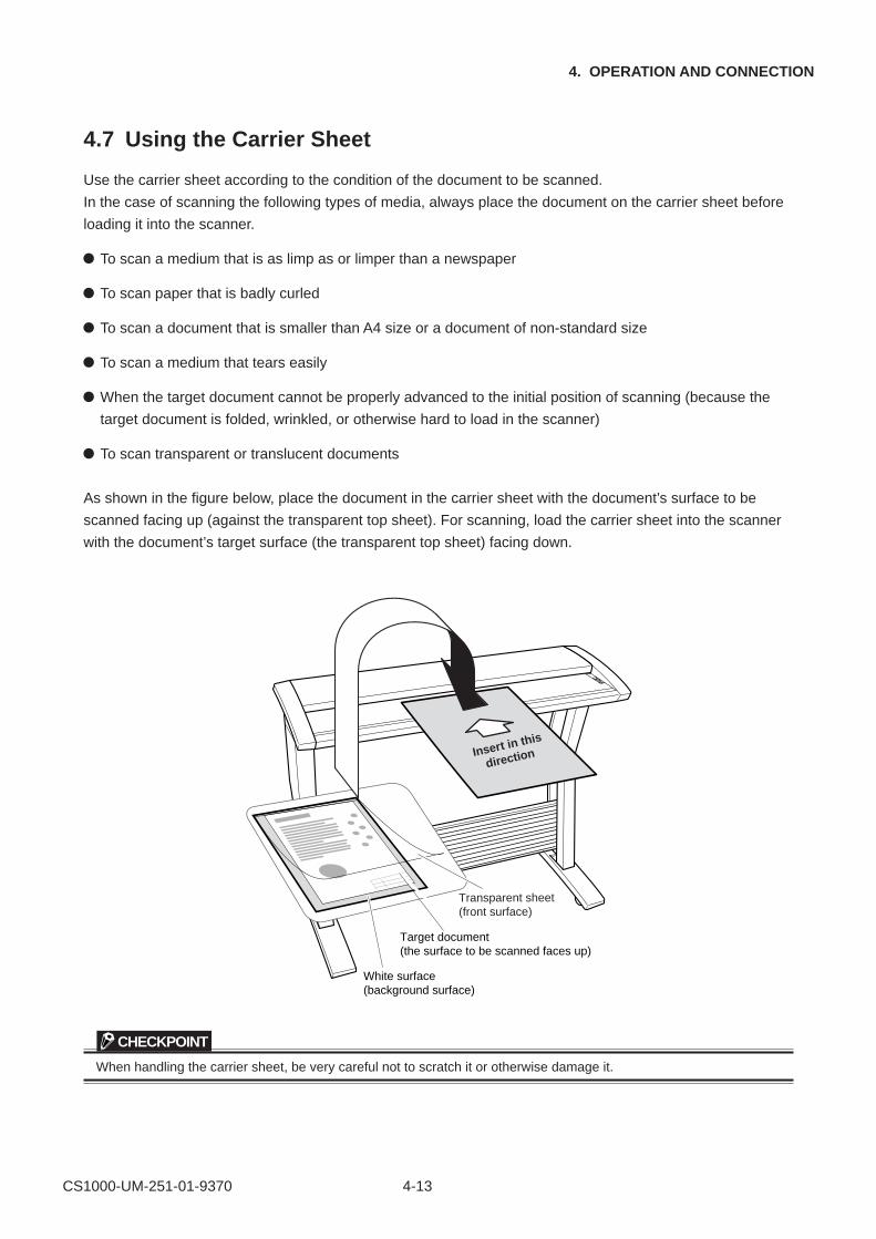
As shown in the figure below, place the document in the carrier sheet with the document’s surface to be
scanned facing up (against the transparent top sheet). For scanning, load the carrier sheet into the scanner
with the document’s target surface (the transparent top sheet) facing down.
Insert in this
direction
Transparent sheet(front surface)
Target document (the surface to be scanned faces up)
White surface (background surface)
CHECKPOINT
When handling the carrier sheet, be very careful not to scratch it or otherwise damage it.
CS1000-UM-251-01-9370 4-14
4. OPERATION AND CONNECTION
4.8 Scanner Driver Software’s Compatibility with Windows 2000
Precautions for installing scanner driver software (Scanning Master, TWAIN32) on your PC
to run under Windows 2000
Running the scanner driver software under Windows 2000 requires the ASPI Manager in addition to the
SCSI board driver software (provided with Windows 2000). This software is to be supplied by Adaptec.

CS1000-UM-251-01-9370 4-15
4. OPERATION AND CONNECTION
4.9 How to Obtain (Install) the ASPI Manager
1. What you will need
(1) Copy of the warranty accompanying the purchased SCSI board
(2) ASPI layer update software available at the Adaptec website
You can find this software or “ASPI32.EXE” among updates at the http://www.adaptec.com/worldwide/
support/driverdetail.html?filekey=aspi32.exe.
2. How to obtain ASPI Manager
ASPI Manager for Windows 2000 will be available at the Adaptec website.
You can find this software at the http://www.adaptec.com.
3. How to install ASPI Manager
(1) Install the SCSI card in your PC.
(2) Install programs in the floppy disk from Adaptec into Windows 2000.
To do this, double-click “Setup32.exe” in the floppy disk.
(3) Use the update software obtained in Step (2) of Section 1 to update the ASPI layer.
When you are finished, you are ready to run the scanner driver.
CS1000-UM-251-01-9370 4-16
4. OPERATION AND CONNECTION
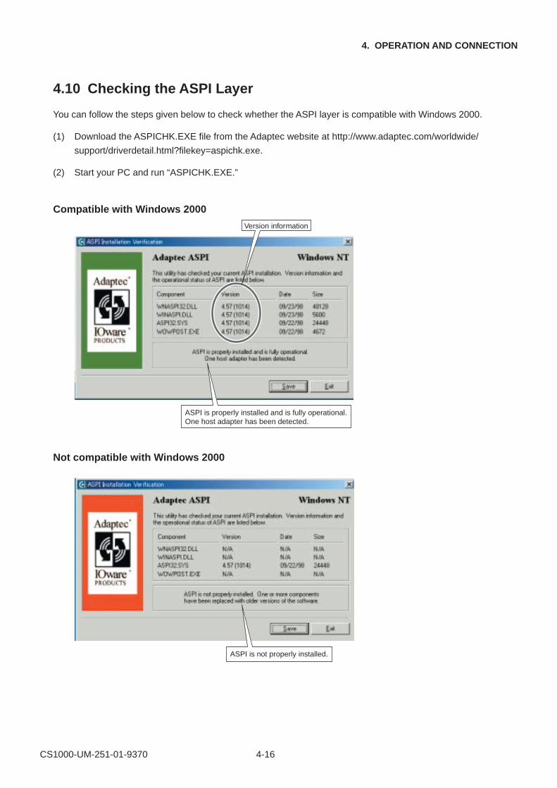
4.10 Checking the ASPI Layer
You can follow the steps given below to check whether the ASPI layer is compatible with Windows 2000.
(1) Download the ASPICHK.EXE file from the Adaptec website at http://www.adaptec.com/worldwide/
support/driverdetail.html?filekey=aspichk.exe.
(2) Start your PC and run “ASPICHK.EXE.”
Compatible with Windows 2000
Version information
ASPI is properly installed and is fully operational.One host adapter has been detected.
Not compatible with Windows 2000
ASPI is not properly installed.
CS1000-UM-251-01-9370 4-17
4. OPERATION AND CONNECTION
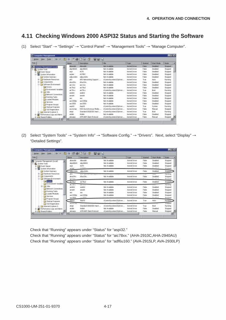
4.11 Checking Windows 2000 ASPI32 Status and Starting the Software
(1) Select “Start” → “Settings” → “Control Panel” → “Management Tools” → “Manage Computer”.
(2) Select “System Tools” → “System Info” → “Software Config.” → “Drivers”. Next, select “Display” →
“Detailed Settings”.
Check that “Running” appears under “Status” for “aspi32.”
Check that “Running” appears under “Status” for “aic78xx.” (AHA-2910C,AHA-2940AU)
Check that “Running” appears under “Status” for “adf6u160.” (AVA-2915LP, AVA-2930LP)
CS1000-UM-251-01-9370 4-18
4. OPERATION AND CONNECTION
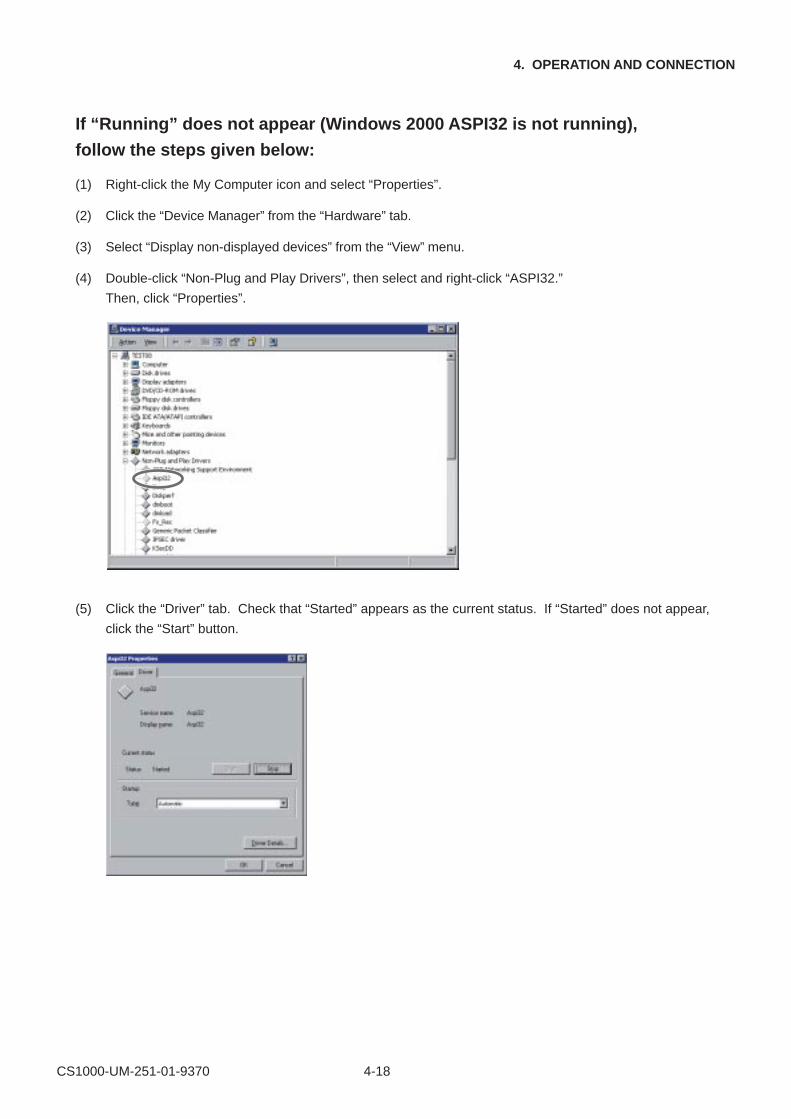
If “Running” does not appear (Windows 2000 ASPI32 is not running),
follow the steps given below:
(1) Right-click the My Computer icon and select “Properties”.
(2) Click the “Device Manager” from the “Hardware” tab.
(3) Select “Display non-displayed devices” from the “View” menu.
(4) Double-click “Non-Plug and Play Drivers”, then select and right-click “ASPI32.”
Then, click “Properties”.
(5) Click the “Driver” tab. Check that “Started” appears as the current status. If “Started” does not appear,
click the “Start” button.
CS1000-UM-251-01-9370 4-19
4. OPERATION AND CONNECTION
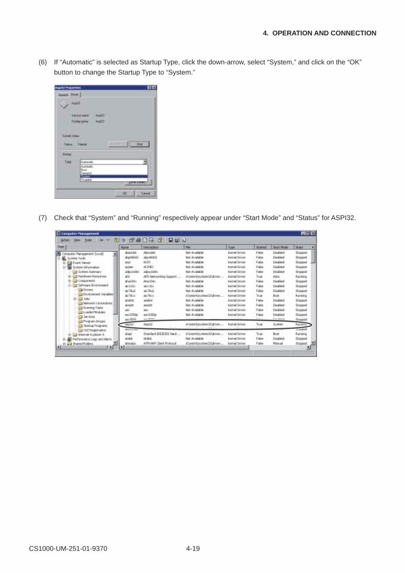
(6) If “Automatic” is selected as Startup Type, click the down-arrow, select “System,” and click on the “OK”
button to change the Startup Type to “System.”
(7) Check that “System” and “Running” respectively appear under “Start Mode” and “Status” for ASPI32.
CS1000-UM-251-01-9370 4-20
4. OPERATION AND CONNECTION
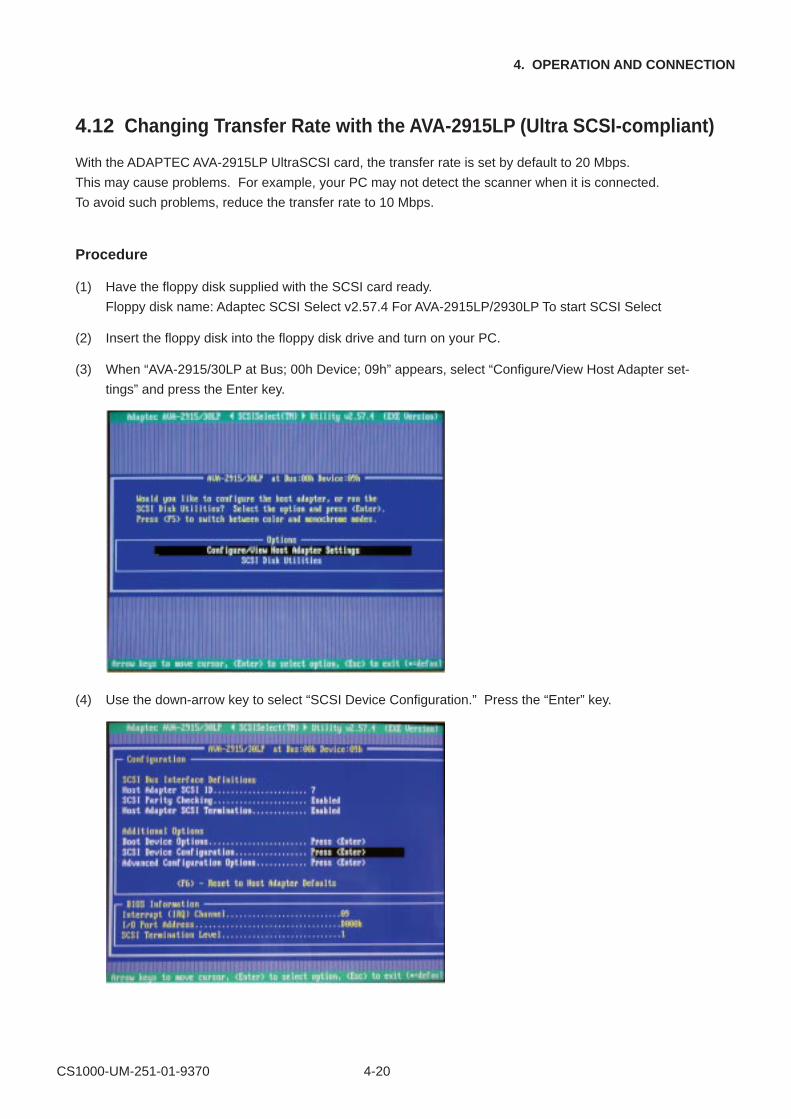
4.12 Changing Transfer Rate with the AVA-2915LP (Ultra SCSI-compliant)
With the ADAPTEC AVA-2915LP UltraSCSI card, the transfer rate is set by default to 20 Mbps.
This may cause problems. For example, your PC may not detect the scanner when it is connected.
To avoid such problems, reduce the transfer rate to 10 Mbps.
Procedure
(1) Have the floppy disk supplied with the SCSI card ready.
Floppy disk name: Adaptec SCSI Select v2.57.4 For AVA-2915LP/2930LP To start SCSI Select
(2) Insert the floppy disk into the floppy disk drive and turn on your PC.
(3) When “AVA-2915/30LP at Bus; 00h Device; 09h” appears, select “Configure/View Host Adapter set-
tings” and press the Enter key.
(4) Use the down-arrow key to select “SCSI Device Configuration.” Press the “Enter” key.
CS1000-UM-251-01-9370 4-21
4. OPERATION AND CONNECTION
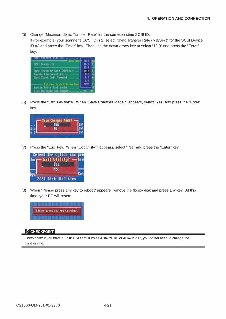
(5) Change “Maximum Sync Transfer Rate” for the corresponding SCSI ID.
If (for example) your scanner’s SCSI ID is 2, select “Sync Transfer Rate (MB/Sec)” for the SCSI Device
ID #2 and press the “Enter” key. Then use the down-arrow key to select “10.0” and press the “Enter”
key.
(6) Press the “Esc” key twice. When “Save Changes Made?” appears, select “Yes” and press the “Enter”
key.
(7) Press the “Esc” key. When “Exit Utility?” appears, select “Yes” and press the “Enter” key.
(8) When “Please press any key to reboot” appears, remove the floppy disk and press any key. At this
time, your PC will restart.
CHECKPOINT
Checkpoint: If you have a FastSCSI card such as AHA-2910C or AHA-1520B, you do not need to change the
transfer rate.
CS1000-UM-251-01-9370 4-22
4. OPERATION AND CONNECTION
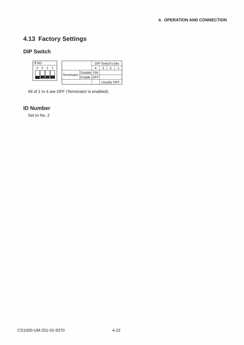
4.13 Factory Settings
DIP Switch
1234
ON
DIP Switch's bits
TerminatorEnableDisable
Usually OFF
OFFON4 3 2 1
All of 1 to 4 are OFF (Terminator is enabled).
ID NumberSet to No. 2
CS1000-UM-251-01-9370 5-1
5. DAILY MAINTENANCE
5. DAILY MAINTENANCE
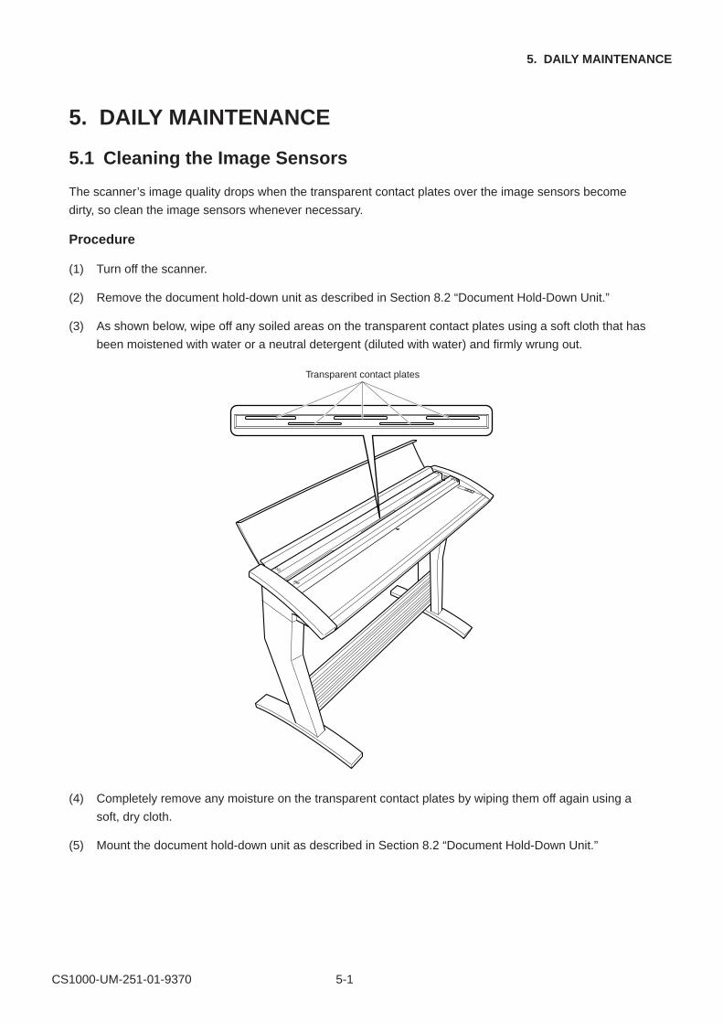
5.1 Cleaning the Image Sensors
The scanner’s image quality drops when the transparent contact plates over the image sensors become
dirty, so clean the image sensors whenever necessary.
Procedure
(1) Turn off the scanner.
(2) Remove the document hold-down unit as described in Section 8.2 “Document Hold-Down Unit.”
(3) As shown below, wipe off any soiled areas on the transparent contact plates using a soft cloth that has
been moistened with water or a neutral detergent (diluted with water) and firmly wrung out.
Transparent contact plates
(4) Completely remove any moisture on the transparent contact plates by wiping them off again using a
soft, dry cloth.
(5) Mount the document hold-down unit as described in Section 8.2 “Document Hold-Down Unit.”
CS1000-UM-251-01-9370 5-2
5. DAILY MAINTENANCE
CHECKPOINT
Do not use a commercial cleaner for office equipment, a glass cleaner, or chemical solvents such as solutions
containing alcohol.
CAUTION
Although the glass base unit is not a maintenance part that requires periodic replacement, it is a consumable part
because its surface may receive slight scratches due to minute particles of dust and other foreign matter. If docu-
ment scanning produces unsatisfactory results (unexpected white or black streaks in the data) due to scratches on
the glass base unit or other reasons, the glass base unit will be replaced for no charge while the service warranty is
in effect but will be replaced for a charge after the service warranty has expired. To request replacement, contact
your nearest Graphtec vendor.
CS1000-UM-251-01-9370 5-3
5. DAILY MAINTENANCE
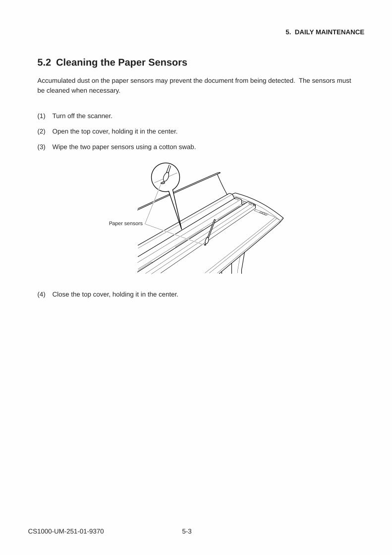
5.2 Cleaning the Paper Sensors
Accumulated dust on the paper sensors may prevent the document from being detected. The sensors must
be cleaned when necessary.
(1) Turn off the scanner.
(2) Open the top cover, holding it in the center.
(3) Wipe the two paper sensors using a cotton swab.
Paper sensors
(4) Close the top cover, holding it in the center.
CS1000-UM-251-01-9370 5-4
5. DAILY MAINTENANCE
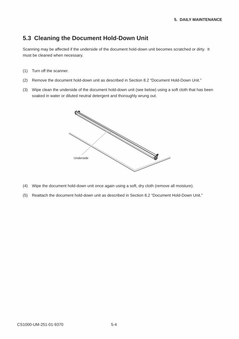
5.3 Cleaning the Document Hold-Down Unit
Scanning may be affected if the underside of the document hold-down unit becomes scratched or dirty. It
must be cleaned when necessary.
(1) Turn off the scanner.
(2) Remove the document hold-down unit as described in Section 8.2 “Document Hold-Down Unit.”
(3) Wipe clean the underside of the document hold-down unit (see below) using a soft cloth that has been
soaked in water or diluted neutral detergent and thoroughly wrung out.
Underside
(4) Wipe the document hold-down unit once again using a soft, dry cloth (remove all moisture).
(5) Reattach the document hold-down unit as described in Section 8.2 “Document Hold-Down Unit.”
CS1000-UM-251-01-9370 5-5
5. DAILY MAINTENANCE
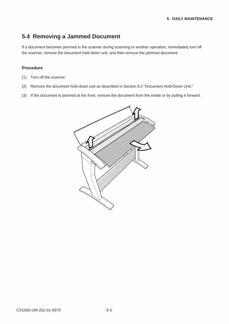
5.4 Removing a Jammed Document
If a document becomes jammed in the scanner during scanning or another operation, immediately turn off
the scanner, remove the document hold-down unit, and then remove the jammed document.
Procedure
(1) Turn off the scanner.
(2) Remove the document hold-down unit as described in Section 8.2 “Document Hold-Down Unit.”
(3) If the document is jammed at the front, remove the document from the inside or by pulling it forward.
CS1000-UM-251-01-9370 5-6
5. DAILY MAINTENANCE
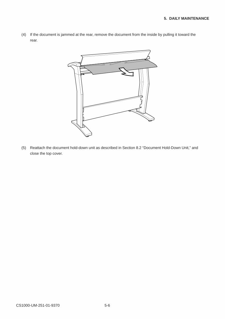
(4) If the document is jammed at the rear, remove the document from the inside by pulling it toward the
rear.
(5) Reattach the document hold-down unit as described in Section 8.2 “Document Hold-Down Unit,” and
close the top cover.
CS1000-UM-251-01-9370 6-1
6. RECOMMENDED PARTS LIST
6. RECOMMENDED PARTS LIST
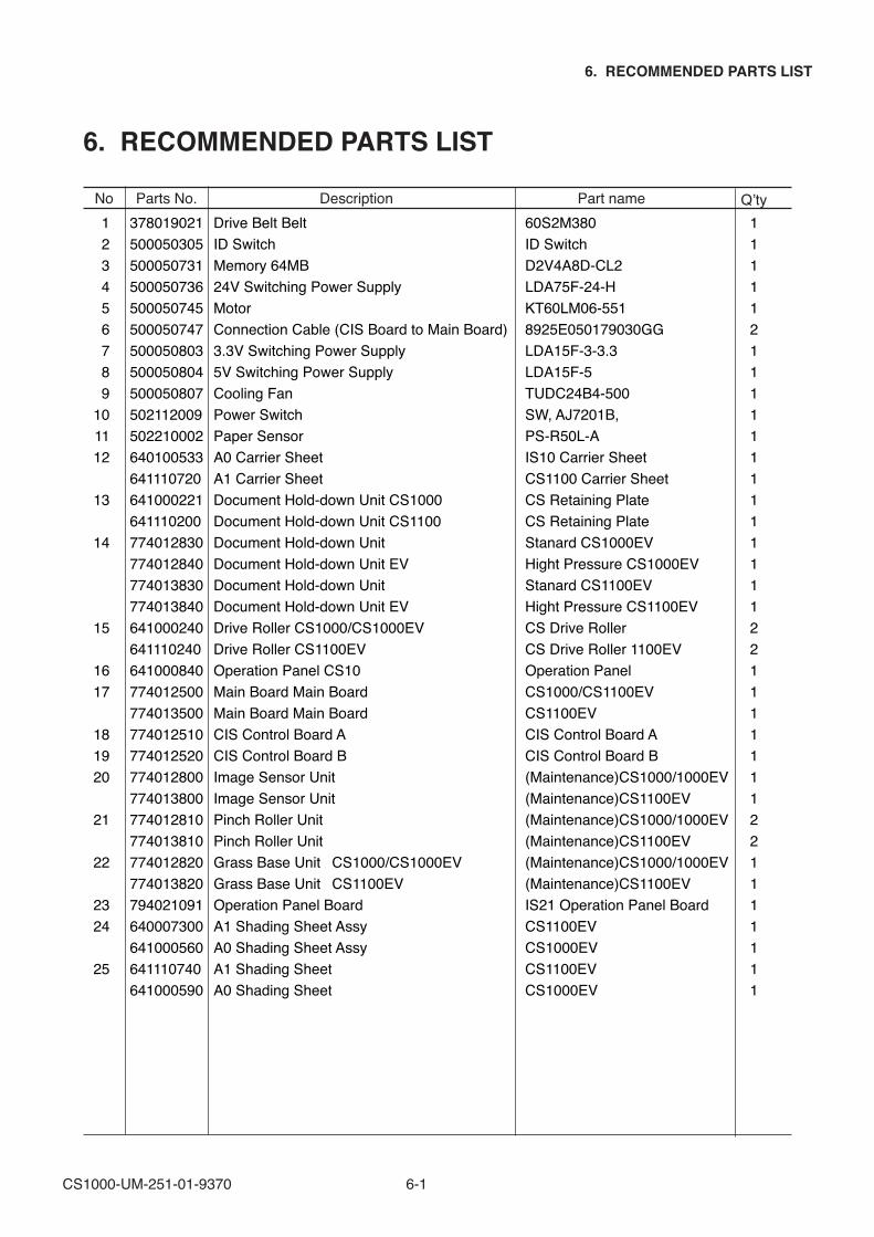
No Parts No. Description Part name Q’ty 1 378019021 Drive Belt Belt 60S2M380 1 2 500050305 ID Switch ID Switch 1 3 500050731 Memory 64MB D2V4A8D-CL2 1 4 500050736 24V Switching Power Supply LDA75F-24-H 1 5 500050745 Motor KT60LM06-551 1 6 500050747 Connection Cable (CIS Board to Main Board) 8925E050179030GG 2 7 500050803 3.3V Switching Power Supply LDA15F-3-3.3 1 8 500050804 5V Switching Power Supply LDA15F-5 1 9 500050807 Cooling Fan TUDC24B4-500 110 502112009 Power Switch SW, AJ7201B, 111 502210002 Paper Sensor PS-R50L-A 112 640100533 A0 Carrier Sheet IS10 Carrier Sheet 1 641110720 A1 Carrier Sheet CS1100 Carrier Sheet 113 641000221 Document Hold-down Unit CS1000 CS Retaining Plate 1 641110200 Document Hold-down Unit CS1100 CS Retaining Plate 114 774012830 Document Hold-down Unit Stanard CS1000EV 1 774012840 Document Hold-down Unit EV Hight Pressure CS1000EV 1 774013830 Document Hold-down Unit Stanard CS1100EV 1 774013840 Document Hold-down Unit EV Hight Pressure CS1100EV 115 641000240 Drive Roller CS1000/CS1000EV CS Drive Roller 2 641110240 Drive Roller CS1100EV CS Drive Roller 1100EV 216 641000840 Operation Panel CS10 Operation Panel 117 774012500 Main Board Main Board CS1000/CS1100EV 1 774013500 Main Board Main Board CS1100EV 118 774012510 CIS Control Board A CIS Control Board A 119 774012520 CIS Control Board B CIS Control Board B 120 774012800 Image Sensor Unit (Maintenance)CS1000/1000EV 1 774013800 Image Sensor Unit (Maintenance)CS1100EV 121 774012810 Pinch Roller Unit (Maintenance)CS1000/1000EV 2 774013810 Pinch Roller Unit (Maintenance)CS1100EV 222 774012820 Grass Base Unit⦆ CS1000/CS1000EV (Maintenance)CS1000/1000EV 1 774013820 Grass Base Unit⦆ CS1100EV (Maintenance)CS1100EV 123 794021091 Operation Panel Board IS21 Operation Panel Board 124 640007300 A1 Shading Sheet Assy CS1100EV 1 641000560 A0 Shading Sheet Assy CS1000EV 125 641110740 A1 Shading Sheet CS1100EV 1 641000590 A0 Shading Sheet CS1000EV 1
CS1000-UM-251-01-9370 7-1
7. LIST OF JIGS AND TOOLS
7. LIST OF JIGS AND TOOLS
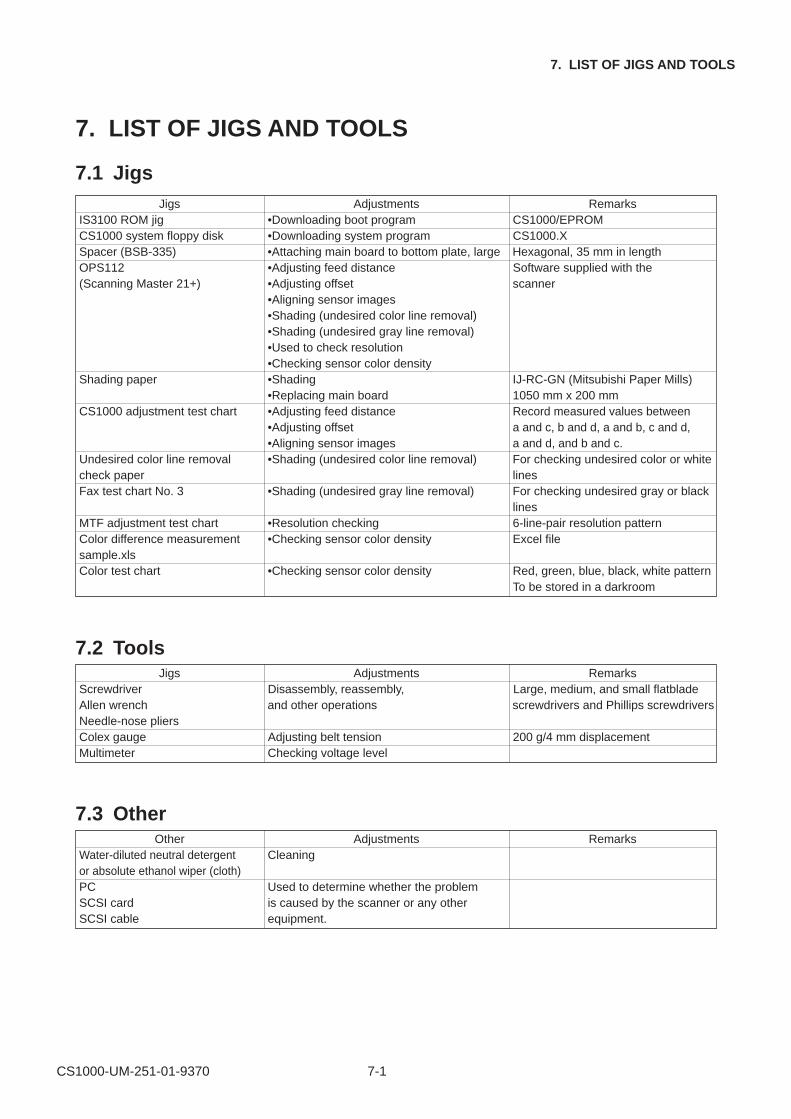
7.1 JigsJigs Adjustments Remarks
IS3100 ROM jig •Downloading boot program CS1000/EPROMCS1000 system floppy disk •Downloading system program CS1000.XSpacer (BSB-335) •Attaching main board to bottom plate, large Hexagonal, 35 mm in lengthOPS112 •Adjusting feed distance Software supplied with the(Scanning Master 21+) •Adjusting offset scanner
•Aligning sensor images•Shading (undesired color line removal)•Shading (undesired gray line removal)•Used to check resolution•Checking sensor color density
Shading paper •Shading IJ-RC-GN (Mitsubishi Paper Mills)•Replacing main board 1050 mm x 200 mm
CS1000 adjustment test chart •Adjusting feed distance Record measured values between•Adjusting offset a and c, b and d, a and b, c and d,•Aligning sensor images a and d, and b and c.
Undesired color line removal •Shading (undesired color line removal) For checking undesired color or whitecheck paper linesFax test chart No. 3 •Shading (undesired gray line removal) For checking undesired gray or black
linesMTF adjustment test chart •Resolution checking 6-line-pair resolution patternColor difference measurement •Checking sensor color density Excel filesample.xlsColor test chart •Checking sensor color density Red, green, blue, black, white pattern
To be stored in a darkroom
7.2 ToolsJigs Adjustments Remarks
Screwdriver Disassembly, reassembly, Large, medium, and small flatbladeAllen wrench and other operations screwdrivers and Phillips screwdriversNeedle-nose pliersColex gauge Adjusting belt tension 200 g/4 mm displacementMultimeter Checking voltage level
7.3 OtherOther Adjustments Remarks
Water-diluted neutral detergent Cleaningor absolute ethanol wiper (cloth)PC Used to determine whether the problemSCSI card is caused by the scanner or any otherSCSI cable equipment.
CS1000-UM-251-01-9370 8-1
8. DISASSEMBLING AND ADJUSTING MECHANICAL PARTS
8. DISASSEMBLING AND ADJUSTING MECHANICAL PARTS
8.1 Considerations before starting disassembly
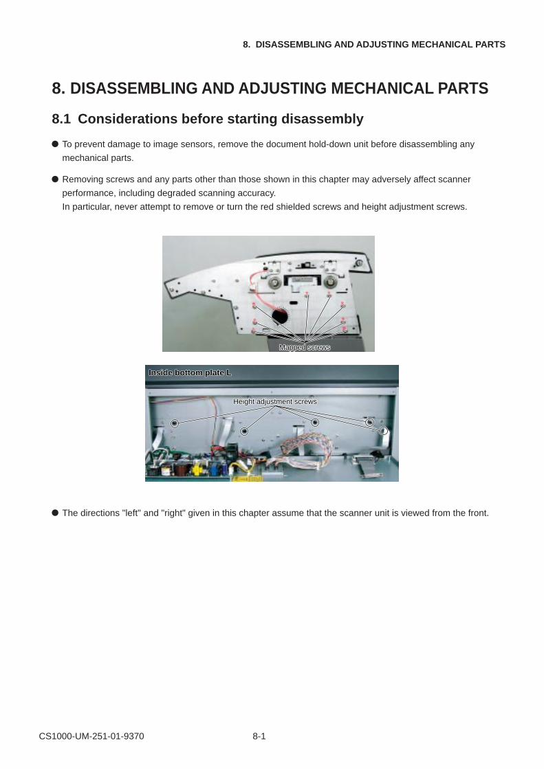
To prevent damage to image sensors, remove the document hold-down unit before disassembling any
mechanical parts.
Removing screws and any parts other than those shown in this chapter may adversely affect scanner
performance, including degraded scanning accuracy.
In particular, never attempt to remove or turn the red shielded screws and height adjustment screws.
Mapped screwsMapped screws
Height adjustment screwsHeight adjustment screws
Inside bottom plate LInside bottom plate L
The directions "left" and "right" given in this chapter assume that the scanner unit is viewed from the front.
CS1000-UM-251-01-9370 8-2
8. DISASSEMBLING AND ADJUSTING MECHANICAL PARTS
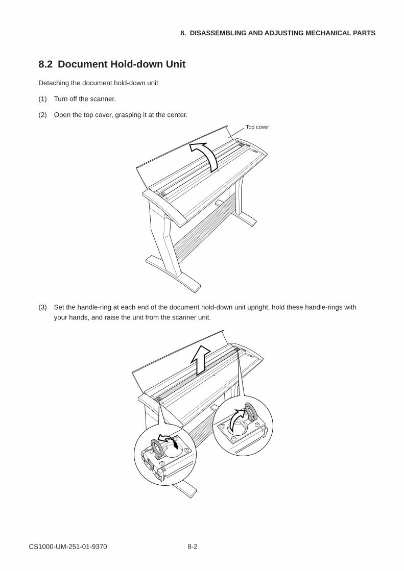
8.2 Document Hold-down Unit
Detaching the document hold-down unit
(1) Turn off the scanner.
(2) Open the top cover, grasping it at the center.
Top cover
(3) Set the handle-ring at each end of the document hold-down unit upright, hold these handle-rings with
your hands, and raise the unit from the scanner unit.
CS1000-UM-251-9370 8-1
8. DISASSEMBLING AND ADJUSTING MECHANICAL PARTS
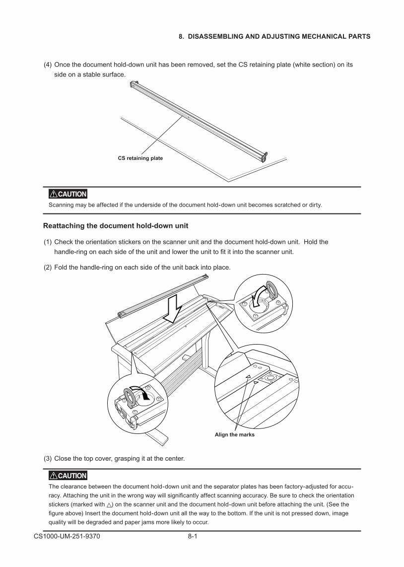
(4) Once the document hold-down unit has been removed, set the CS retaining plate (white section) on its
side on a stable surface.
CS retaining plate
Scanning may be affected if the underside of the document hold-down unit becomes scratched or dirty.
Reattaching the document hold-down unit
(1) Check the orientation stickers on the scanner unit and the document hold-down unit. Hold the
handle-ring on each side of the unit and lower the unit to fit it into the scanner unit.
(2) Fold the handle-ring on each side of the unit back into place.
Align the marks
(3) Close the top cover, grasping it at the center.
The clearance between the document hold-down unit and the separator plates has been factory-adjusted for accu-
racy. Attaching the unit in the wrong way will significantly affect scanning accuracy. Be sure to check the orientation
stickers (marked with ) on the scanner unit and the document hold-down unit before attaching the unit. (See the
figure above) Insert the document hold-down unit all the way to the bottom. If the unit is not pressed down, image
quality will be degraded and paper jams more likely to occur.
CS1000-UM-251-9370 8-2
8. DISASSEMBLING AND ADJUSTING MECHANICAL PARTS
8.3 CS Retaining Plate
Disassembly procedure
Detaching the document �hold-down unit
Detaching the �CS retaining plate
8.2 p.8-2 This Section
Detaching the CS Retaining Plate
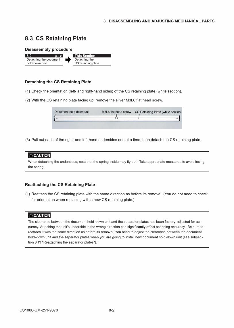
(1) Check the orientation (left- and right-hand sides) of the CS retaining plate (white section).
(2) With the CS retaining plate facing up, remove the silver M3L6 flat head screw.
M3L6 flat head screw CS Retaining Plate (white section)Document hold-down unit
(3) Pull out each of the right- and left-hand undersides one at a time, then detach the CS retaining plate.
When detaching the undersides, note that the spring inside may fly out. Take appropriate measures to avoid losing
the spring.
Reattaching the CS Retaining Plate
(1) Reattach the CS retaining plate with the same direction as before its removal. (You do not need to check
for orientation when replacing with a new CS retaining plate.)
The clearance between the document hold-down unit and the separator plates has been factory-adjusted for ac-
curacy. Attaching the unit's underside in the wrong direction can significantly affect scanning accuracy. Be sure to
reattach it with the same direction as before its removal. You need to adjust the clearance between the document
hold-down unit and the separator plates when you are going to install new document hold-down unit (see subsec-
tion 8.13 "Reattaching the separator plates").
CS1000-UM-251-01-9370 8-5
8. DISASSEMBLING AND ADJUSTING MECHANICAL PARTS
8.4 Side Covers
Disassembly procedure
Detaching the document hold-down unit
Detaching the side covers
8.2 p.8-2 This Section
Detaching the side covers
(1) Remove the four black M4L6 binding head screws on each side of the scanner unit. (Both sides)
M4L6 binding head screws
(2) Detach the side covers.
Reattaching the side covers
(1) Reattach the side covers in the reverse order in which they were detached.
(2) Make sure the clearance between the top cover and each of the side covers is 1 mm or less.
1 mm max.
Top cover
Side cover
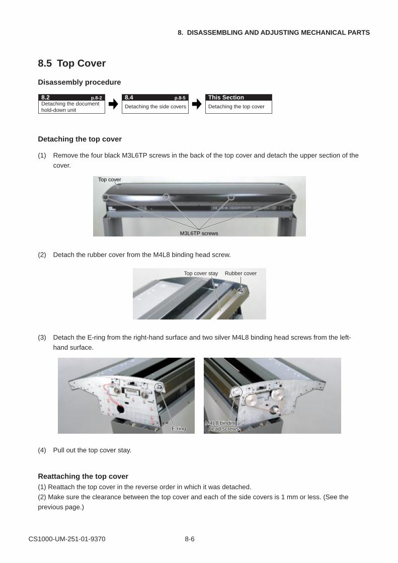
CS1000-UM-251-01-9370 8-6
8. DISASSEMBLING AND ADJUSTING MECHANICAL PARTS
8.5 Top Cover
Disassembly procedure
Detaching the document hold-down unit
Detaching the top cover
8.2 p.8-2 This SectionDetaching the side covers
8.4 p.8-5
Detaching the top cover
(1) Remove the four black M3L6TP screws in the back of the top cover and detach the upper section of the
cover.
M3L6TP screws
Top cover
(2) Detach the rubber cover from the M4L8 binding head screw.
Rubber coverTop cover stay
(3) Detach the E-ring from the right-hand surface and two silver M4L8 binding head screws from the left-
hand surface.
E-ringE-ringM4L8 binding
head screwsM4L8 binding
head screws
(4) Pull out the top cover stay.
Reattaching the top cover(1) Reattach the top cover in the reverse order in which it was detached.
(2) Make sure the clearance between the top cover and each of the side covers is 1 mm or less. (See the
previous page.)
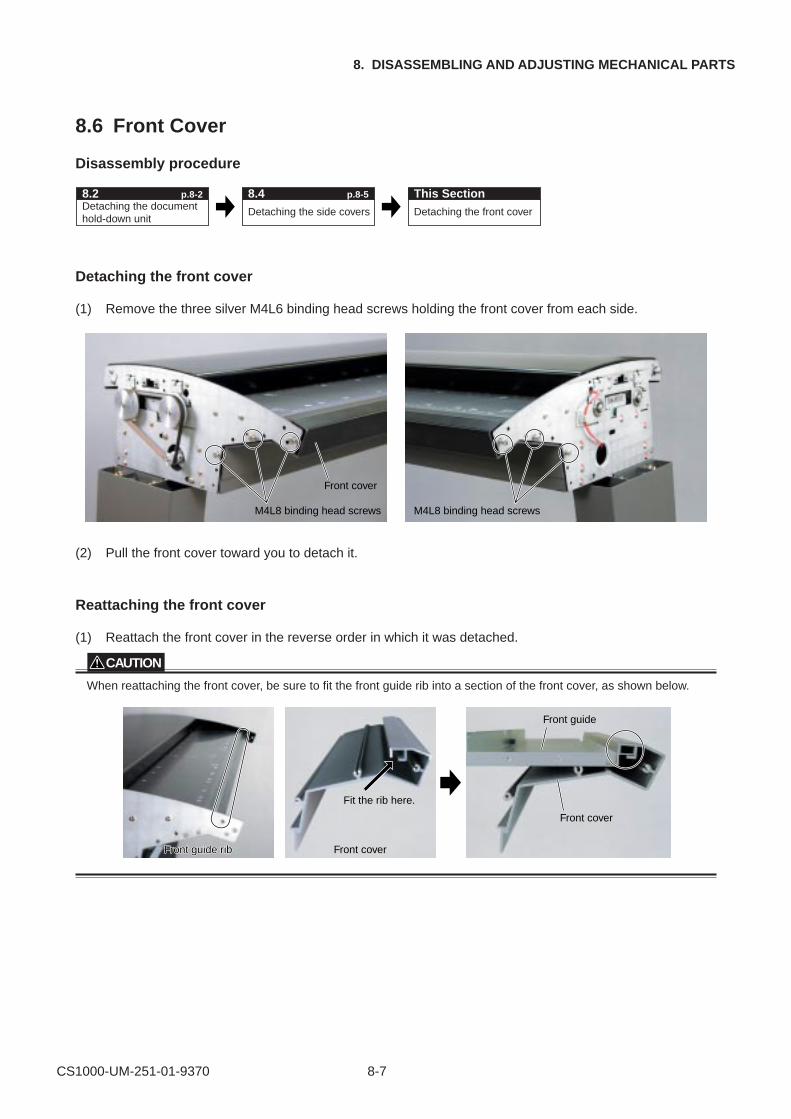
CS1000-UM-251-01-9370 8-7
8. DISASSEMBLING AND ADJUSTING MECHANICAL PARTS
8.6 Front Cover
Disassembly procedure
Detaching the document hold-down unit
Detaching the front cover
8.2 p.8-2 This SectionDetaching the side covers
8.4 p.8-5
Detaching the front cover
(1) Remove the three silver M4L6 binding head screws holding the front cover from each side.
M4L8 binding head screws
Front cover
M4L8 binding head screws
(2) Pull the front cover toward you to detach it.
Reattaching the front cover
(1) Reattach the front cover in the reverse order in which it was detached.
CAUTION
When reattaching the front cover, be sure to fit the front guide rib into a section of the front cover, as shown below.
Front guide ribFront guide rib Front cover
Fit the rib here.
Front cover
Front guide
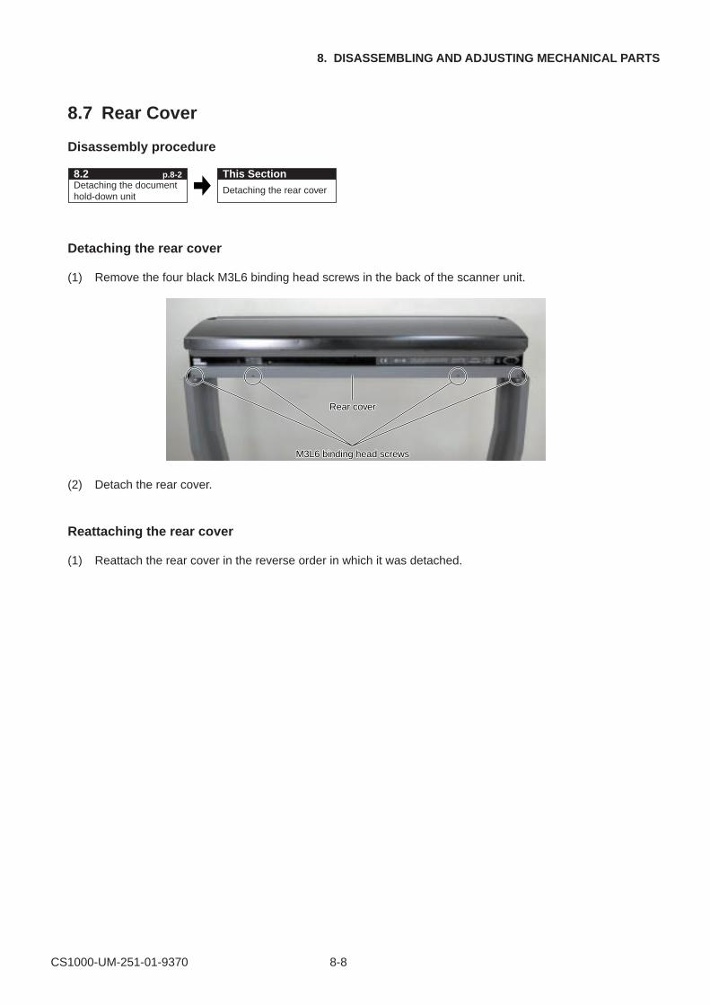
CS1000-UM-251-01-9370 8-8
8. DISASSEMBLING AND ADJUSTING MECHANICAL PARTS
8.7 Rear Cover
Disassembly procedure
Detaching the document hold-down unit
8.2 p.8-2 This SectionDetaching the rear cover
Detaching the rear cover
(1) Remove the four black M3L6 binding head screws in the back of the scanner unit.
M3L6 binding head screwsM3L6 binding head screws
Rear coverRear cover
(2) Detach the rear cover.
Reattaching the rear cover
(1) Reattach the rear cover in the reverse order in which it was detached.
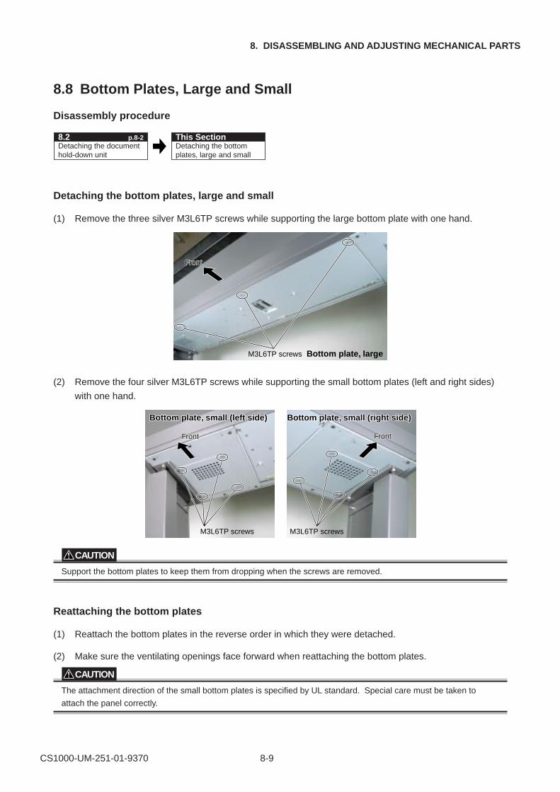
CS1000-UM-251-01-9370 8-9
8. DISASSEMBLING AND ADJUSTING MECHANICAL PARTS
8.8 Bottom Plates, Large and Small
Disassembly procedure
Detaching the document hold-down unit
Detaching the bottom plates, large and small
8.2 p.8-2 This Section
Detaching the bottom plates, large and small
(1) Remove the three silver M3L6TP screws while supporting the large bottom plate with one hand.
M3L6TP screws
FrontFront
Bottom plate, large
(2) Remove the four silver M3L6TP screws while supporting the small bottom plates (left and right sides)
with one hand.
M3L6TP screws M3L6TP screws
FrontFront FrontFront
Bottom plate, small (left side)Bottom plate, small (left side) Bottom plate, small (right side)Bottom plate, small (right side)
CAUTION
Support the bottom plates to keep them from dropping when the screws are removed.
Reattaching the bottom plates
(1) Reattach the bottom plates in the reverse order in which they were detached.
(2) Make sure the ventilating openings face forward when reattaching the bottom plates.
CAUTION
The attachment direction of the small bottom plates is specified by UL standard. Special care must be taken to
attach the panel correctly.
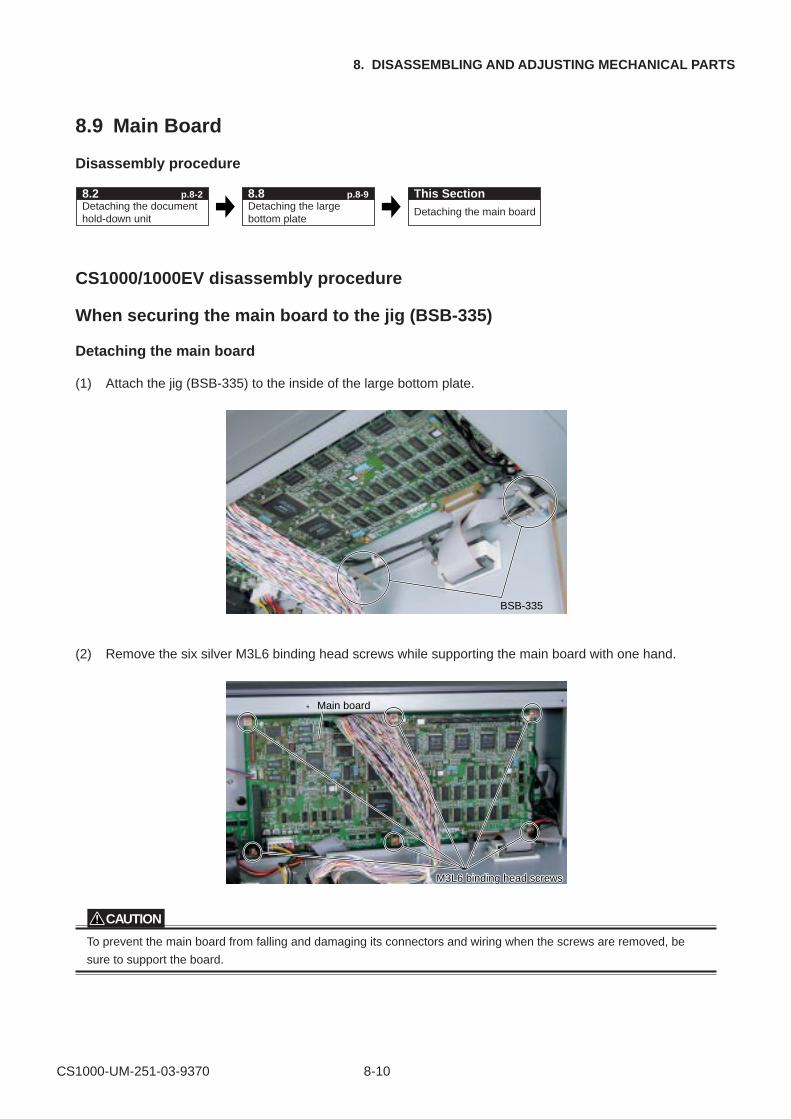
CS1000-UM-251-03-9370 8-10
8. DISASSEMBLING AND ADJUSTING MECHANICAL PARTS
8.9 Main Board
Disassembly procedure
Detaching the document hold-down unit
Detaching the large bottom plate
Detaching the main board
8.2 p.8-2 This Section8.8 p.8-9
CS1000/1000EV disassembly procedure
When securing the main board to the jig (BSB-335)
Detaching the main board
(1) Attach the jig (BSB-335) to the inside of the large bottom plate.
BSB-335
(2) Remove the six silver M3L6 binding head screws while supporting the main board with one hand.
M3L6 binding head screM3L6 binding head screwswsM3L6 binding head screws
Main board
CAUTION
To prevent the main board from falling and damaging its connectors and wiring when the screws are removed, be
sure to support the board.
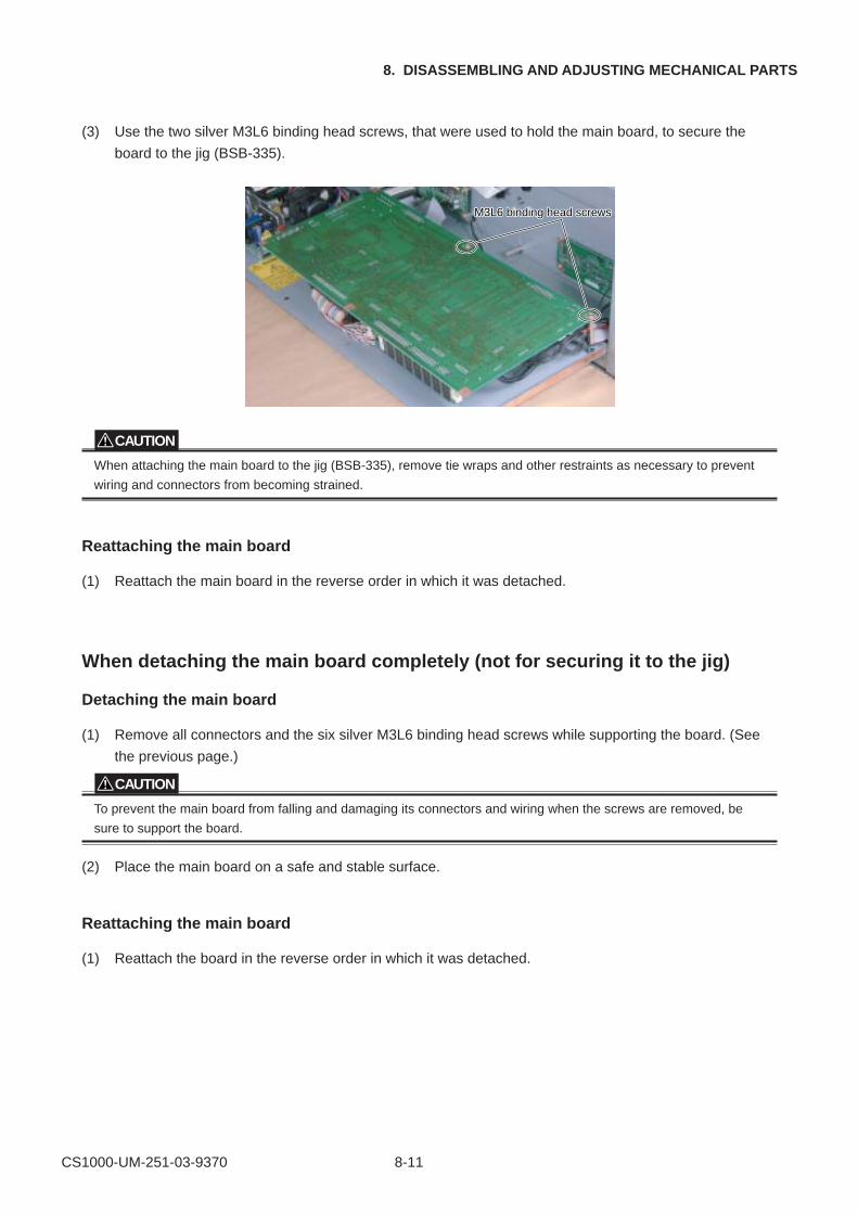
CS1000-UM-251-03-9370 8-11
8. DISASSEMBLING AND ADJUSTING MECHANICAL PARTS
(3) Use the two silver M3L6 binding head screws, that were used to hold the main board, to secure the
board to the jig (BSB-335).
M3L6 binding head screM3L6 binding head screwswsM3L6 binding head screws
CAUTION
When attaching the main board to the jig (BSB-335), remove tie wraps and other restraints as necessary to prevent
wiring and connectors from becoming strained.
Reattaching the main board
(1) Reattach the main board in the reverse order in which it was detached.
When detaching the main board completely (not for securing it to the jig)
Detaching the main board
(1) Remove all connectors and the six silver M3L6 binding head screws while supporting the board. (See
the previous page.)
CAUTION
To prevent the main board from falling and damaging its connectors and wiring when the screws are removed, be
sure to support the board.
(2) Place the main board on a safe and stable surface.
Reattaching the main board
(1) Reattach the board in the reverse order in which it was detached.
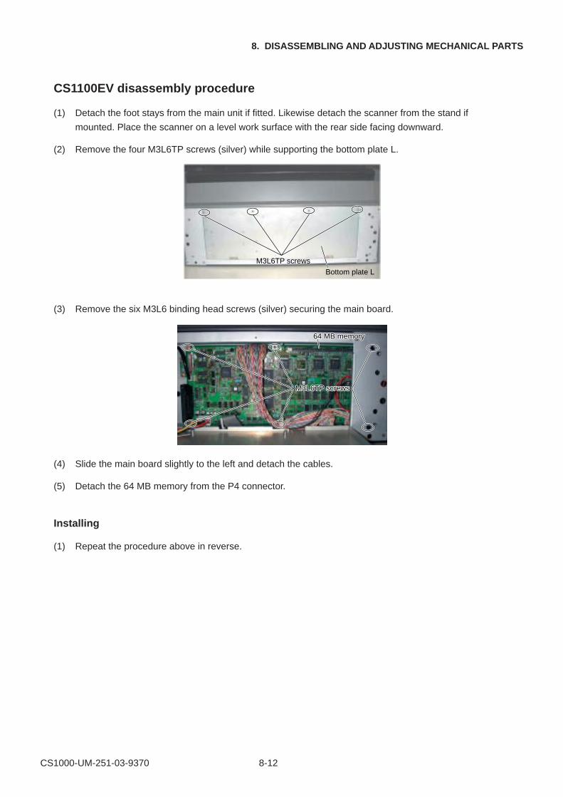
CS1000-UM-251-03-9370 8-12
8. DISASSEMBLING AND ADJUSTING MECHANICAL PARTS
CS1100EV disassembly procedure
(1) Detach the foot stays from the main unit if fitted. Likewise detach the scanner from the stand if
mounted. Place the scanner on a level work surface with the rear side facing downward.
(2) Remove the four M3L6TP screws (silver) while supporting the bottom plate L.
M3L6TP screws
Bottom plate L
(3) Remove the six M3L6 binding head screws (silver) securing the main board.
M3L6TP screwsM3L6TP screws
64 MB memory64 MB memory
(4) Slide the main board slightly to the left and detach the cables.
(5) Detach the 64 MB memory from the P4 connector.
Installing
(1) Repeat the procedure above in reverse.
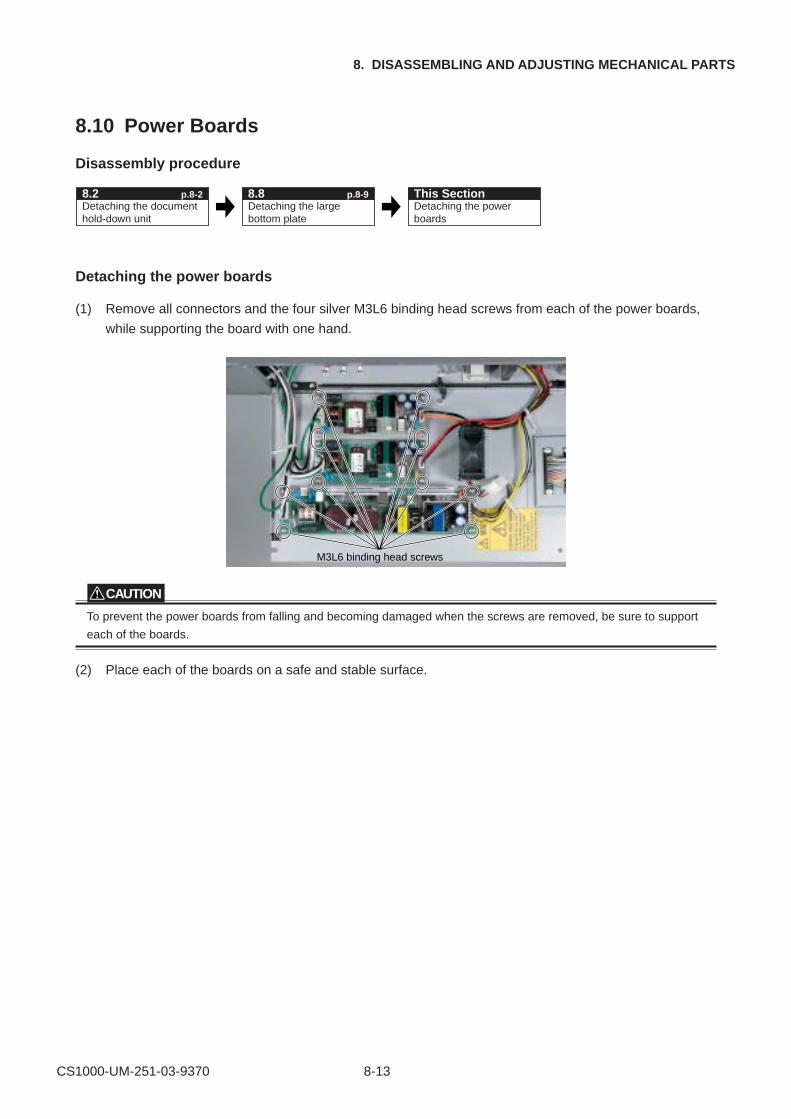
CS1000-UM-251-03-9370 8-13
8. DISASSEMBLING AND ADJUSTING MECHANICAL PARTS
8.10 Power Boards
Disassembly procedure
Detaching the document hold-down unit
Detaching the large bottom plate
Detaching the power boards
8.2 p.8-2 This Section8.8 p.8-9
Detaching the power boards
(1) Remove all connectors and the four silver M3L6 binding head screws from each of the power boards,
while supporting the board with one hand.
M3L6 binding head screws
CAUTION
To prevent the power boards from falling and becoming damaged when the screws are removed, be sure to support
each of the boards.
(2) Place each of the boards on a safe and stable surface.
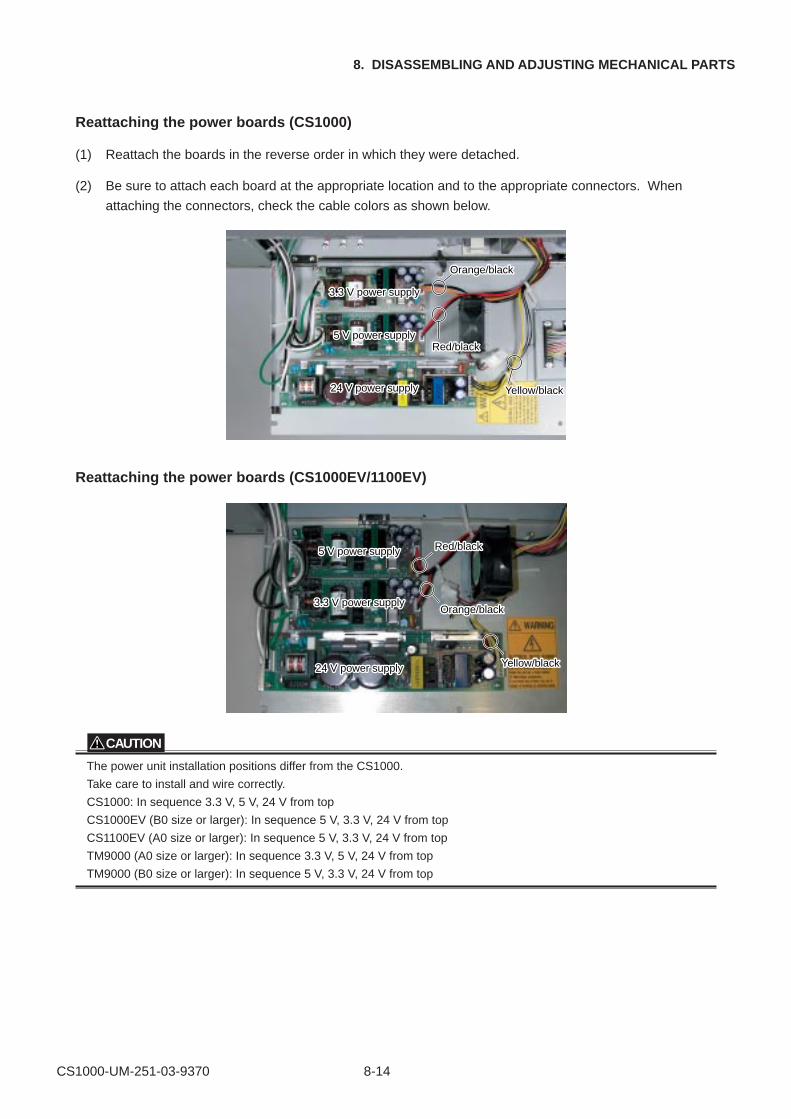
CS1000-UM-251-03-9370 8-14
8. DISASSEMBLING AND ADJUSTING MECHANICAL PARTS
Reattaching the power boards (CS1000)
(1) Reattach the boards in the reverse order in which they were detached.
(2) Be sure to attach each board at the appropriate location and to the appropriate connectors. When
attaching the connectors, check the cable colors as shown below.
3.3 V power supply3.3 V power supply3.3 V power supply
5 V power supply5 V power supply5 V power supply
24 V power supply24 V power supply24 V power supply
Orange/blackOrange/blackOrange/black
Red/blackRed/blackRed/black
Yellow/blackellow/blackYellow/black
Reattaching the power boards (CS1000EV/1100EV)
3.3 V power supply3.3 V power supply3.3 V power supply
5 V power supply5 V power supply5 V power supply
24 V power supply24 V power supply24 V power supply
Orange/blackOrange/blackOrange/black
Red/blackRed/blackRed/black
Yellow/blackellow/blackYellow/black
CAUTION
The power unit installation positions differ from the CS1000.
Take care to install and wire correctly.
CS1000: In sequence 3.3 V, 5 V, 24 V from top
CS1000EV (B0 size or larger): In sequence 5 V, 3.3 V, 24 V from top
CS1100EV (A0 size or larger): In sequence 5 V, 3.3 V, 24 V from top
TM9000 (A0 size or larger): In sequence 3.3 V, 5 V, 24 V from top
TM9000 (B0 size or larger): In sequence 5 V, 3.3 V, 24 V from top
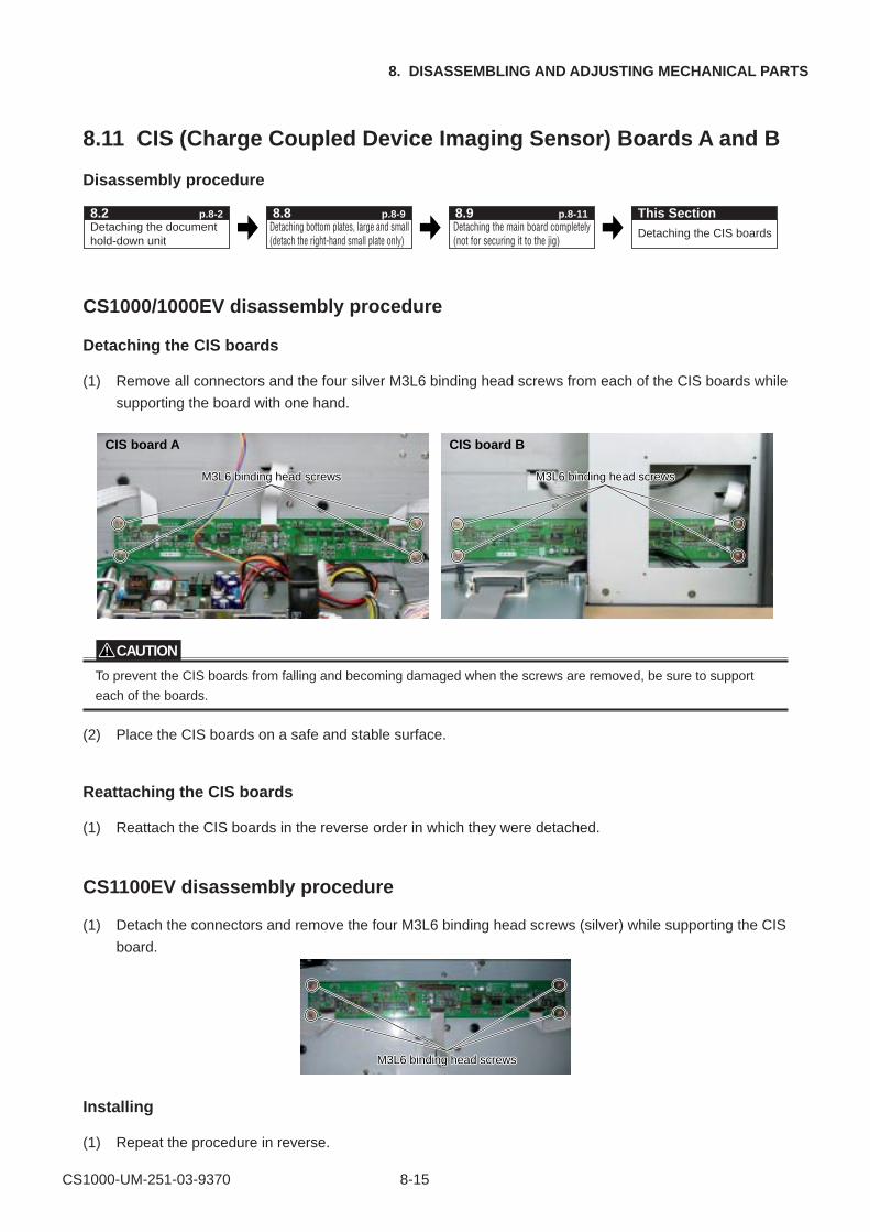
CS1000-UM-251-03-9370 8-15
8. DISASSEMBLING AND ADJUSTING MECHANICAL PARTS
8.11 CIS (Charge Coupled Device Imaging Sensor) Boards A and B
Disassembly procedure
Detaching the document hold-down unit
Detaching bottom plates, large and small (detach the right-hand small plate only)
Detaching the CIS boards
8.2 p.8-2 This Section8.8 p.8-9Detaching the main board completely (not for securing it to the jig)
8.9 p.8-11
CS1000/1000EV disassembly procedure
Detaching the CIS boards
(1) Remove all connectors and the four silver M3L6 binding head screws from each of the CIS boards while
supporting the board with one hand.
M3L6 binding head screwsM3L6 binding head screwsM3L6 binding head screws
CIS board B
M3L6 binding head screwsM3L6 binding head screwsM3L6 binding head screws
CIS board A
CAUTION
To prevent the CIS boards from falling and becoming damaged when the screws are removed, be sure to support
each of the boards.
(2) Place the CIS boards on a safe and stable surface.
Reattaching the CIS boards
(1) Reattach the CIS boards in the reverse order in which they were detached.
CS1100EV disassembly procedure
(1) Detach the connectors and remove the four M3L6 binding head screws (silver) while supporting the CIS
board.
M3L6 binding head screwsM3L6 binding head screws
Installing
(1) Repeat the procedure in reverse.
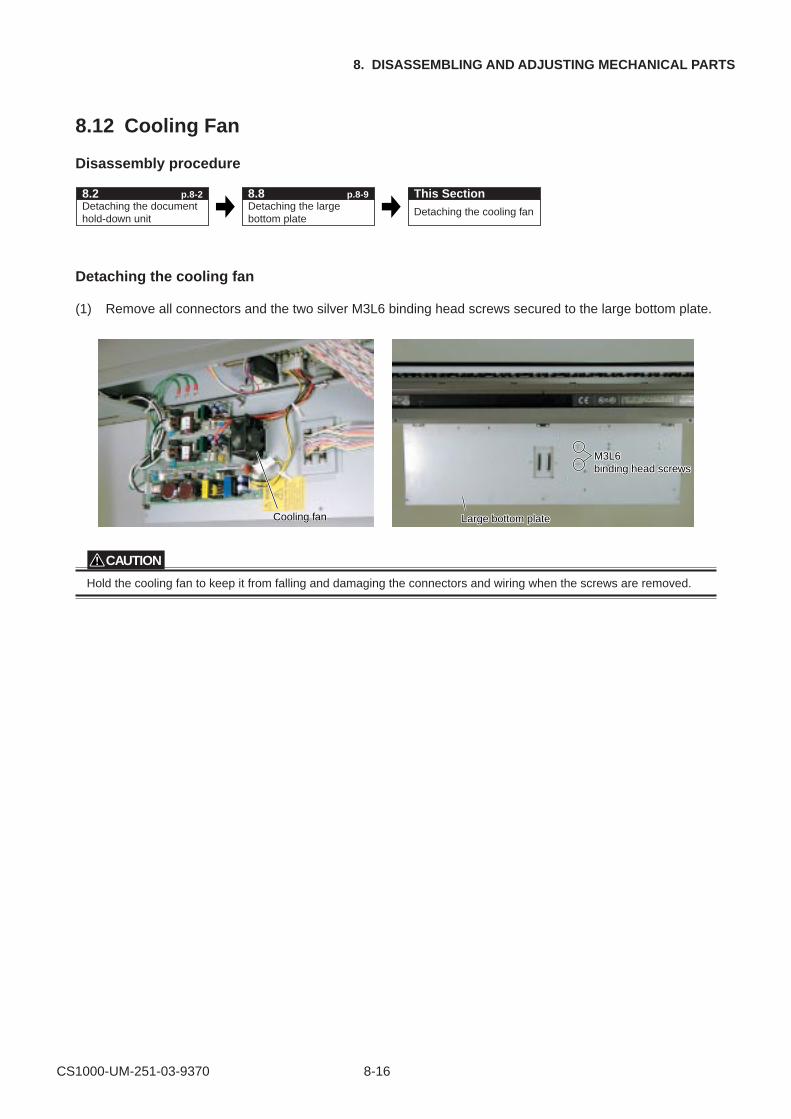
CS1000-UM-251-03-9370 8-16
8. DISASSEMBLING AND ADJUSTING MECHANICAL PARTS
8.12 Cooling Fan
Disassembly procedure
Detaching the document hold-down unit
Detaching the large bottom plate
Detaching the cooling fan
8.2 p.8-2 This Section8.8 p.8-9
Detaching the cooling fan
(1) Remove all connectors and the two silver M3L6 binding head screws secured to the large bottom plate.
M3L6 M3L6 binding head screbinding head screwswsM3L6 binding head screws
Cooling fCooling fananCooling fan Large bottom plateLarge bottom plateLarge bottom plate
CAUTION
Hold the cooling fan to keep it from falling and damaging the connectors and wiring when the screws are removed.
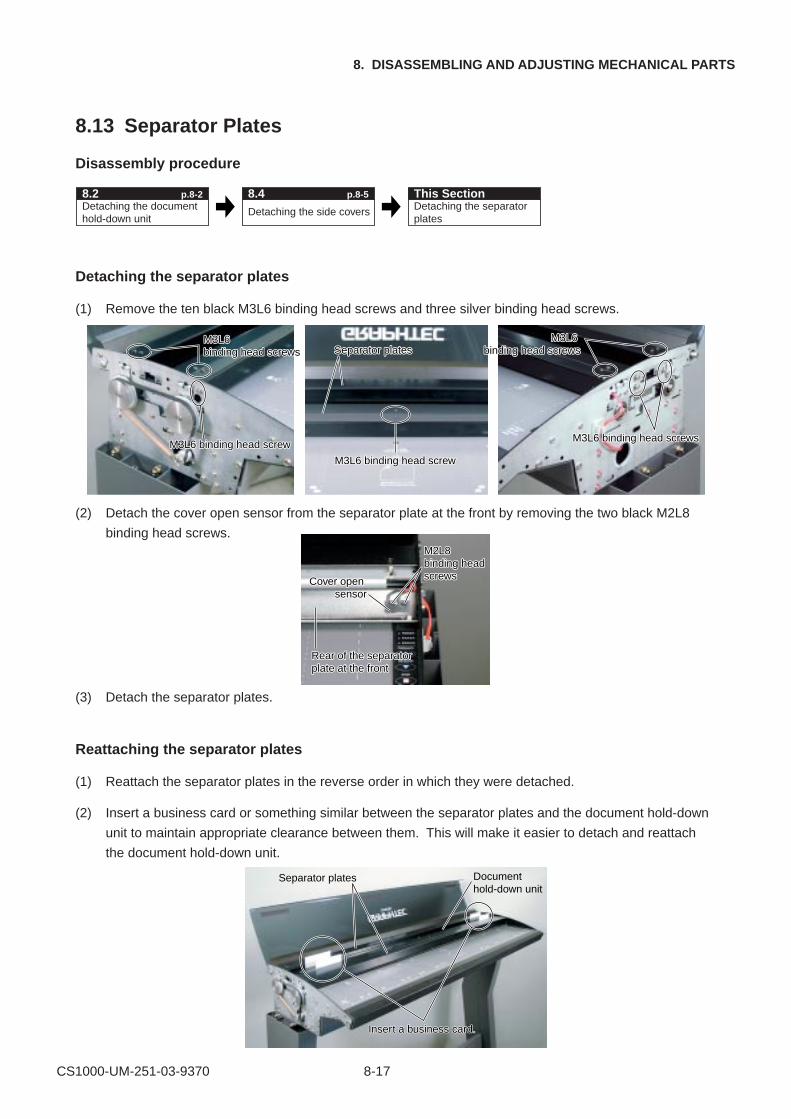
CS1000-UM-251-03-9370 8-17
8. DISASSEMBLING AND ADJUSTING MECHANICAL PARTS
8.13 Separator Plates
Disassembly procedure
Detaching the document hold-down unit
Detaching the side covers Detaching the separator plates
8.2 p.8-2 This Section8.4 p.8-5
Detaching the separator plates
(1) Remove the ten black M3L6 binding head screws and three silver binding head screws.
M3L6 binding head screwsM3L6 binding head screws
M3L6 binding head screwsM3L6 binding head screws
M3L6 binding head screwM3L6 binding head screw
M3L6 binding head screwM3L6 binding head screw
Separator platesSeparator platesM3L6
binding head screwsM3L6
binding head screws
(2) Detach the cover open sensor from the separator plate at the front by removing the two black M2L8
binding head screws.M2L8 M2L8 binding head screws
M2L8 binding head screwsCover open
sensorCover open
sensor
Rear of the separator plate at the frontRear of the separator plate at the front
(3) Detach the separator plates.
Reattaching the separator plates
(1) Reattach the separator plates in the reverse order in which they were detached.
(2) Insert a business card or something similar between the separator plates and the document hold-down
unit to maintain appropriate clearance between them. This will make it easier to detach and reattach
the document hold-down unit.
Separator plates
Insert a business card.Insert a business card.
Document hold-down unit
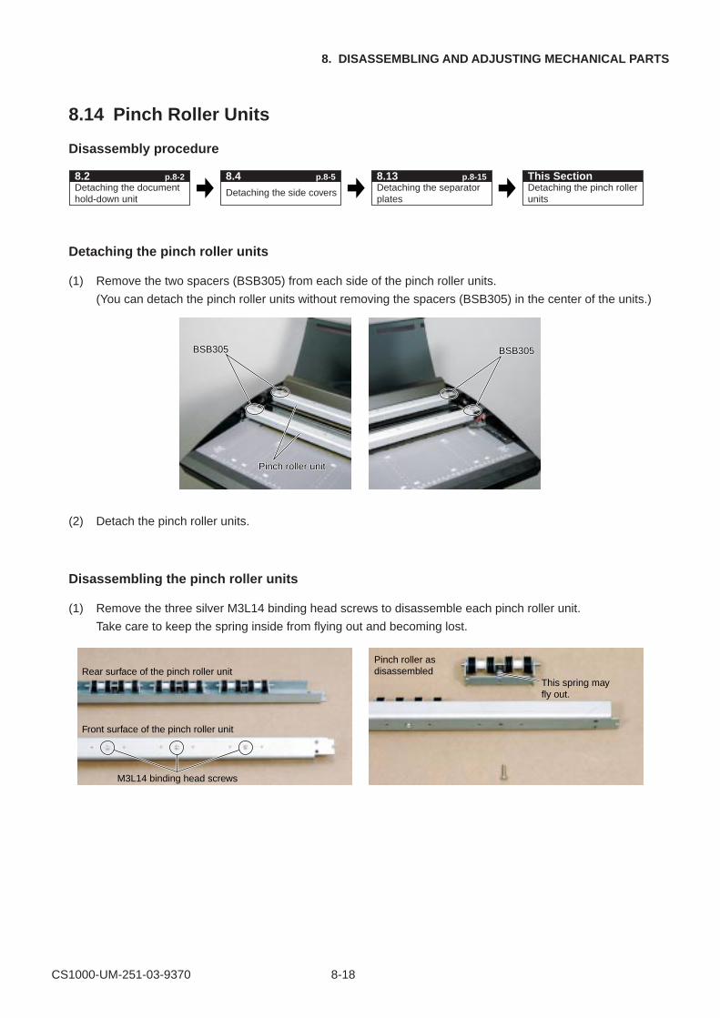
CS1000-UM-251-03-9370 8-18
8. DISASSEMBLING AND ADJUSTING MECHANICAL PARTS
8.14 Pinch Roller Units
Disassembly procedure
Detaching the document hold-down unit
Detaching the side covers Detaching the pinch roller units
8.2 p.8-2 This Section8.4 p.8-5Detaching the separator plates
8.13 p.8-15
Detaching the pinch roller units
(1) Remove the two spacers (BSB305) from each side of the pinch roller units.
(You can detach the pinch roller units without removing the spacers (BSB305) in the center of the units.)
BSB305BSB305BSB305
Pinch roller unitPinch roller unitPinch roller unit
BSB305BSB305BSB305
(2) Detach the pinch roller units.
Disassembling the pinch roller units
(1) Remove the three silver M3L14 binding head screws to disassemble each pinch roller unit.
Take care to keep the spring inside from flying out and becoming lost.
Rear surface of the pinch roller unitPinch roller as disassembled
Front surface of the pinch roller unit
M3L14 binding head screws
This spring may fly out.
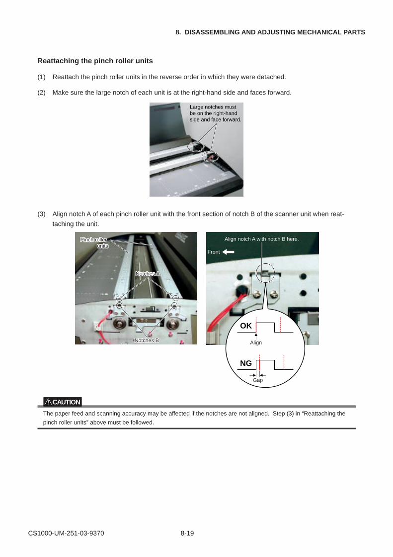
CS1000-UM-251-03-9370 8-19
8. DISASSEMBLING AND ADJUSTING MECHANICAL PARTS
Reattaching the pinch roller units
(1) Reattach the pinch roller units in the reverse order in which they were detached.
(2) Make sure the large notch of each unit is at the right-hand side and faces forward.
Large notches must be on the right-hand side and face forward.
(3) Align notch A of each pinch roller unit with the front section of notch B of the scanner unit when reat-
taching the unit.
Pinch roller Pinch roller unitsunits
Pinch roller units
Notches Notches ANotches A
Notches BNotches BNotches B
Front
OK
NG
Align notch A with notch B here.
Align
Gap
CAUTION
The paper feed and scanning accuracy may be affected if the notches are not aligned. Step (3) in “Reattaching the
pinch roller units” above must be followed.
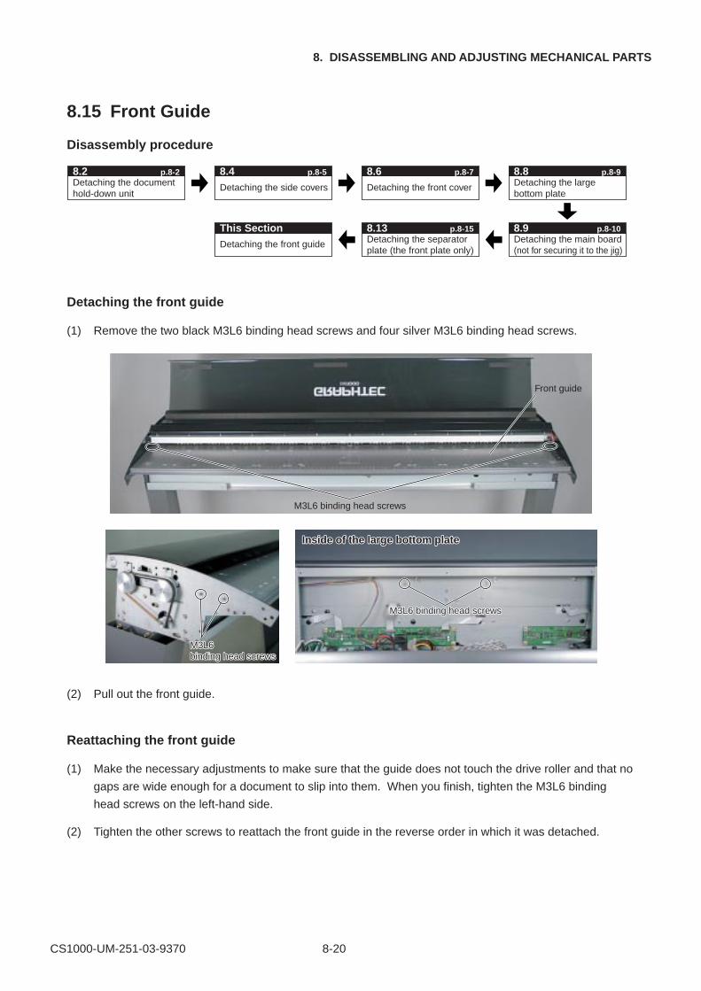
CS1000-UM-251-03-9370 8-20
8. DISASSEMBLING AND ADJUSTING MECHANICAL PARTS
8.15 Front Guide
Disassembly procedure
Detaching the document hold-down unit
8.2 p.8-2
Detaching the side covers Detaching the front cover Detaching the large bottom plate
Detaching the front guide
This SectionDetaching the separator plate (the front plate only)
Detaching the main board(not for securing it to the jig)
8.4 p.8-5 8.6 p.8-7 8.8 p.8-9
8.13 p.8-15 8.9 p.8-10
Detaching the front guide
(1) Remove the two black M3L6 binding head screws and four silver M3L6 binding head screws.
M3L6 binding head screws
M3L6 M3L6 binding head screwswsM3L6 binding head screws
M3L6 binding head screM3L6 binding head screwswsM3L6 binding head screws
Inside of the large bottom plateInside of the large bottom plate
Front guide
(2) Pull out the front guide.
Reattaching the front guide
(1) Make the necessary adjustments to make sure that the guide does not touch the drive roller and that no
gaps are wide enough for a document to slip into them. When you finish, tighten the M3L6 binding
head screws on the left-hand side.
(2) Tighten the other screws to reattach the front guide in the reverse order in which it was detached.
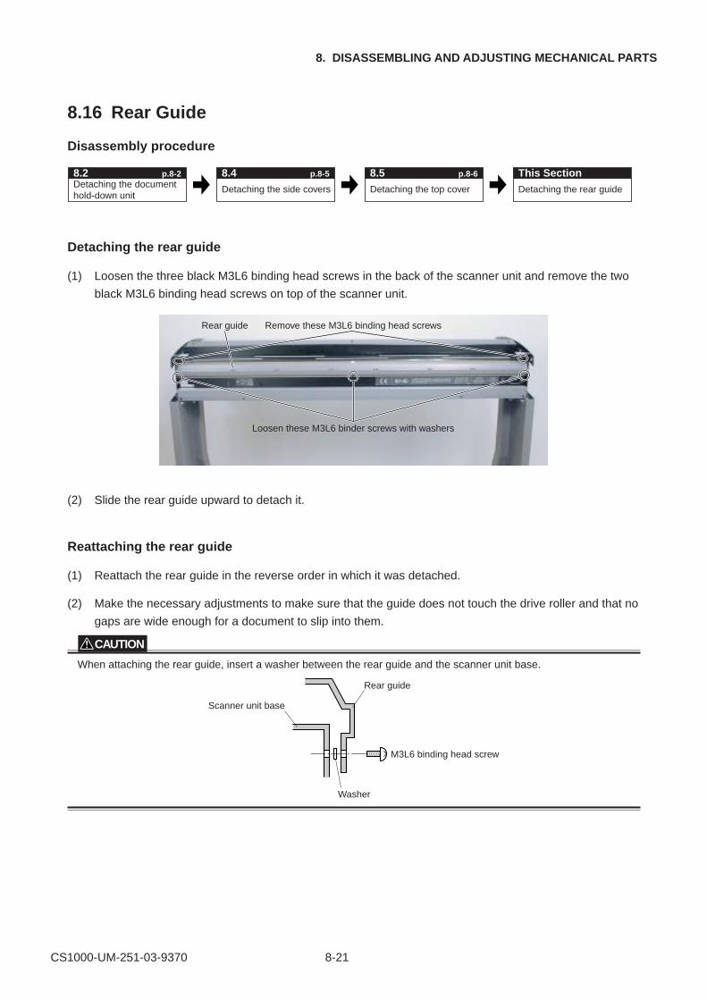
CS1000-UM-251-03-9370 8-21
8. DISASSEMBLING AND ADJUSTING MECHANICAL PARTS
8.16 Rear Guide
Disassembly procedure
Detaching the document hold-down unit
Detaching the side covers Detaching the rear guide
8.2 p.8-2 This Section8.4 p.8-5
Detaching the top cover
8.5 p.8-6
Detaching the rear guide
(1) Loosen the three black M3L6 binding head screws in the back of the scanner unit and remove the two
black M3L6 binding head screws on top of the scanner unit.
Loosen these M3L6 binder screws with washers
Remove these M3L6 binding head screwsRear guide
(2) Slide the rear guide upward to detach it.
Reattaching the rear guide
(1) Reattach the rear guide in the reverse order in which it was detached.
(2) Make the necessary adjustments to make sure that the guide does not touch the drive roller and that no
gaps are wide enough for a document to slip into them.
CAUTION
When attaching the rear guide, insert a washer between the rear guide and the scanner unit base.
M3L6 binding head screw
Washer
Scanner unit base
Rear guide
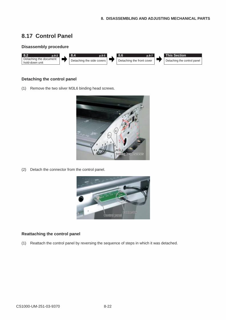
CS1000-UM-251-03-9370 8-22
8. DISASSEMBLING AND ADJUSTING MECHANICAL PARTS
8.17 Control Panel
Disassembly procedure
Detaching the document hold-down unit
Detaching the side covers Detaching the control panel
8.2 p.8-2 This Section8.4 p.8-5
Detaching the front cover
8.6 p.8-7
Detaching the control panel
(1) Remove the two silver M3L6 binding head screws.
M3L6 binding head screwsM3L6 binding head screws
(2) Detach the connector from the control panel.
ConnectorConnectorControl panelControl panel
Reattaching the control panel
(1) Reattach the control panel by reversing the sequence of steps in which it was detached.
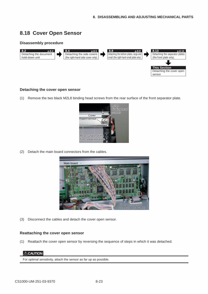
CS1000-UM-251-03-9370 8-23
8. DISASSEMBLING AND ADJUSTING MECHANICAL PARTS
8.18 Cover Open Sensor
Disassembly procedure
Detaching the document hold-down unit
8.2 p.8-2Detaching the side covers (the right-hand side cover only)
Detaching the bottom plates, large and small (the right-hand small plate only)
Detaching the separator plates (the front plate only)
Detaching the cover open sensor
8.4 p.8-5 8.8 p.8-9 8.13 p.8-15
This Section
Detaching the cover open sensor
(1) Remove the two black M2L8 binding head screws from the rear surface of the front separator plate.
M2L8 M2L8 binding head screws
M2L8 binding head screws
Cover open sensor
Cover open sensor
Rear surface of the front separator plateRear surface of the front separator plate
(2) Detach the main board connectors from the cables.
CoCover open sensor er open sensor connector (red cabconnector (red cable)Cover open sensor connector (red cable)
Main board
(3) Disconnect the cables and detach the cover open sensor.
Reattaching the cover open sensor
(1) Reattach the cover open sensor by reversing the sequence of steps in which it was detached.
CAUTION
For optimal sensitivity, attach the sensor as far up as possible.
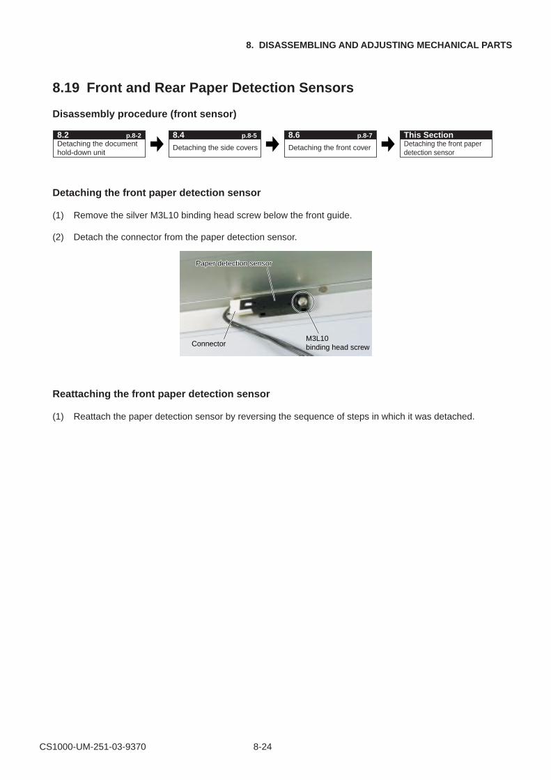
CS1000-UM-251-03-9370 8-24
8. DISASSEMBLING AND ADJUSTING MECHANICAL PARTS
8.19 Front and Rear Paper Detection Sensors
Disassembly procedure (front sensor)
Detaching the document hold-down unit
Detaching the side covers Detaching the front paper detection sensor
8.2 p.8-2 This Section8.4 p.8-5
Detaching the front cover
8.6 p.8-7
Detaching the front paper detection sensor
(1) Remove the silver M3L10 binding head screw below the front guide.
(2) Detach the connector from the paper detection sensor.
M3L10 binding head screwConnector
Paper detection sensorPaper detection sensor
Reattaching the front paper detection sensor
(1) Reattach the paper detection sensor by reversing the sequence of steps in which it was detached.
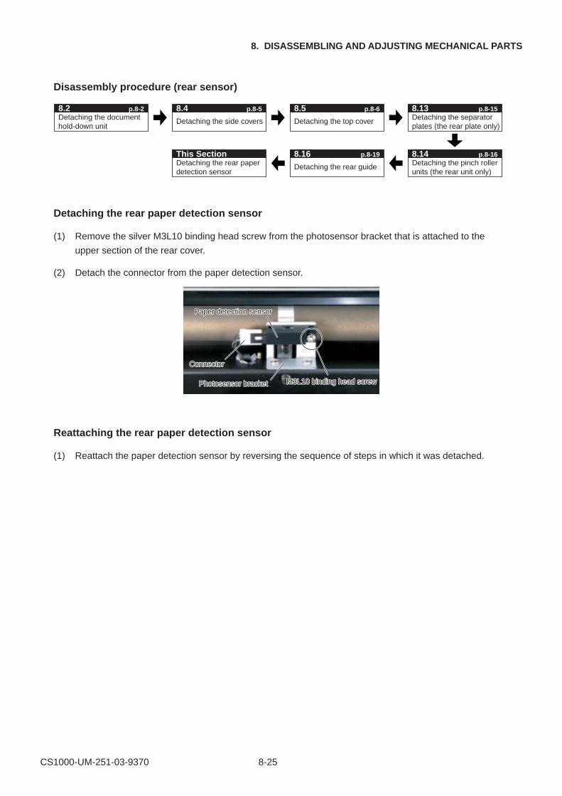
CS1000-UM-251-03-9370 8-25
8. DISASSEMBLING AND ADJUSTING MECHANICAL PARTS
Disassembly procedure (rear sensor)
Detaching the document hold-down unit
8.2 p.8-2
Detaching the side covers Detaching the top cover Detaching the separator plates (the rear plate only)
Detaching the rear paper detection sensor
This SectionDetaching the rear guide Detaching the pinch roller
units (the rear unit only)
8.4 p.8-5 8.5 p.8-6 8.13 p.8-15
8.16 p.8-19 8.14 p.8-16
Detaching the rear paper detection sensor
(1) Remove the silver M3L10 binding head screw from the photosensor bracket that is attached to the
upper section of the rear cover.
(2) Detach the connector from the paper detection sensor.
M3L10 binding head screw
Connector
Photosensor bracket
Paper detection sensor
M3L10 binding head screw
Connector
Photosensor bracket
Paper detection sensor
Reattaching the rear paper detection sensor
(1) Reattach the paper detection sensor by reversing the sequence of steps in which it was detached.
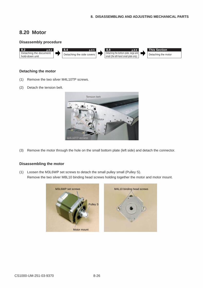
CS1000-UM-251-03-9370 8-26
8. DISASSEMBLING AND ADJUSTING MECHANICAL PARTS
8.20 Motor
Disassembly procedure
Detaching the document hold-down unit
Detaching the side covers Detaching the motor
8.2 p.8-2 This Section8.4 p.8-5Detaching the bottom plate, large and small (the left-hand small plate only)
8.8 p.8-9
Detaching the motor
(1) Remove the two silver M4L10TP screws.
(2) Detach the tension belt.
M4L10TP screws
Pulley
Tension belt
Motor
M4L10TP screws
Pulley
Tension belt
Motor
(3) Remove the motor through the hole on the small bottom plate (left side) and detach the connector.
Disassembling the motor
(1) Loosen the M3L6WP set screws to detach the small pulley small (Pulley S).
Remove the two silver M8L10 binding head screws holding together the motor and motor mount.
M3L6WP set screws
Pulley S
Motor mount
M4L10 binding head screws
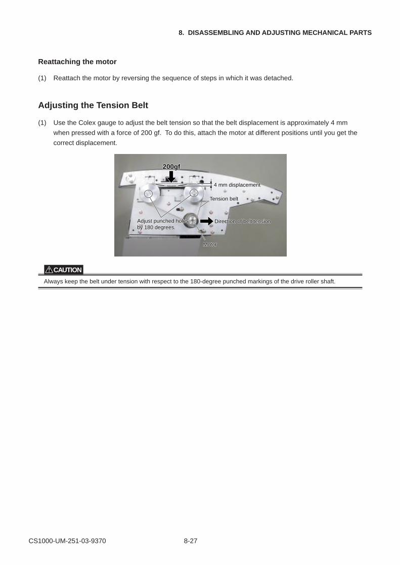
CS1000-UM-251-03-9370 8-27
8. DISASSEMBLING AND ADJUSTING MECHANICAL PARTS
Reattaching the motor
(1) Reattach the motor by reversing the sequence of steps in which it was detached.
Adjusting the Tension Belt
(1) Use the Colex gauge to adjust the belt tension so that the belt displacement is approximately 4 mm
when pressed with a force of 200 gf. To do this, attach the motor at different positions until you get the
correct displacement.
200gf200gf200gf
4 mm displacement4 mm displacement
Direction of belt tensionDirection of belt tension
Tension beltension belt
Adjust punched holes Adjust punched holes by 180 degy 180 degreesrees.
MotorMotor
4 mm displacement
Direction of belt tension
Tension belt
Adjust punched holes by 180 degrees.
Motor
CAUTION
Always keep the belt under tension with respect to the 180-degree punched markings of the drive roller shaft.
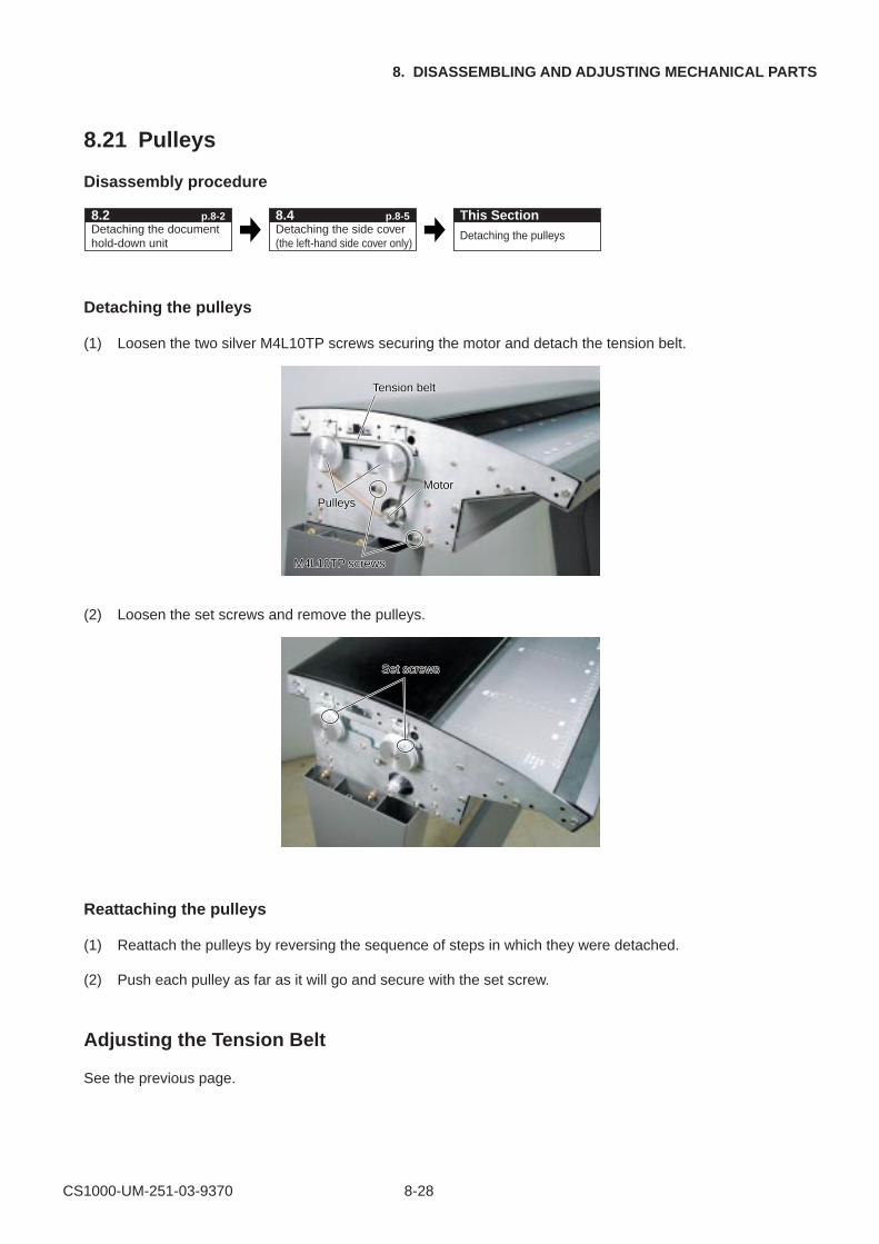
CS1000-UM-251-03-9370 8-28
8. DISASSEMBLING AND ADJUSTING MECHANICAL PARTS
8.21 Pulleys
Disassembly procedure
Detaching the document hold-down unit
Detaching the side cover (the left-hand side cover only)
Detaching the pulleys
8.2 p.8-2 This Section8.4 p.8-5
Detaching the pulleys
(1) Loosen the two silver M4L10TP screws securing the motor and detach the tension belt.
M4L10TP screws
Pulleys
Tension belt
Motor
M4L10TP screws
Pulleys
Tension belt
Motor
(2) Loosen the set screws and remove the pulleys.
Set screwsSet screws
Reattaching the pulleys
(1) Reattach the pulleys by reversing the sequence of steps in which they were detached.
(2) Push each pulley as far as it will go and secure with the set screw.
Adjusting the Tension Belt
See the previous page.
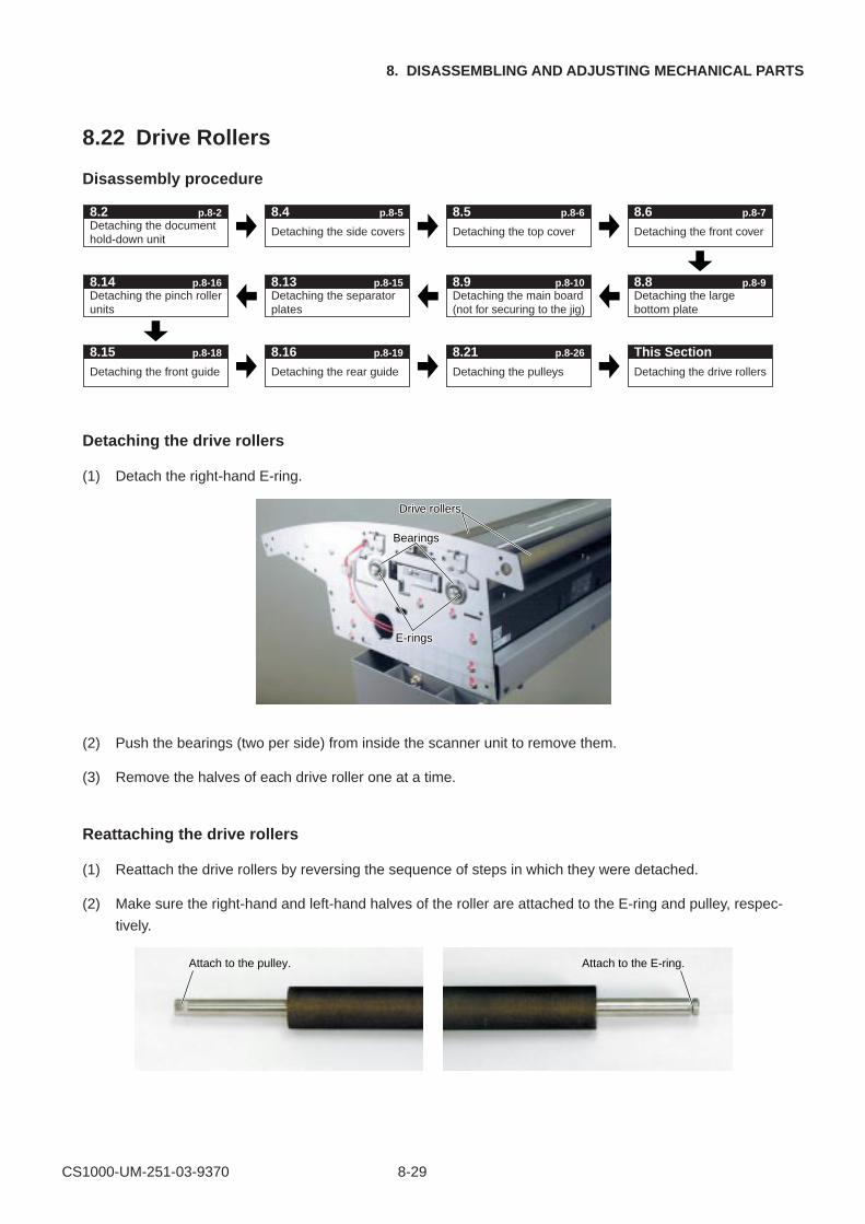
CS1000-UM-251-03-9370 8-29
8. DISASSEMBLING AND ADJUSTING MECHANICAL PARTS
8.22 Drive Rollers
Disassembly procedure
Detaching the document hold-down unit
8.2 p.8-2
Detaching the side covers Detaching the top cover Detaching the front cover
Detaching the pinch roller units
8.14 p.8-16Detaching the separator plates
Detaching the main board (not for securing to the jig)
Detaching the large bottom plate
Detaching the front guide
8.15 p.8-18
Detaching the rear guide Detaching the pulleys Detaching the drive rollers
This Section
8.4 p.8-5 8.5 p.8-6 8.6 p.8-7
8.13 p.8-15 8.9 p.8-10 8.8 p.8-9
8.16 p.8-19 8.21 p.8-26
Detaching the drive rollers
(1) Detach the right-hand E-ring.
E-rings
Bearings
Drive rollers
E-rings
Bearings
Drive rollers
(2) Push the bearings (two per side) from inside the scanner unit to remove them.
(3) Remove the halves of each drive roller one at a time.
Reattaching the drive rollers
(1) Reattach the drive rollers by reversing the sequence of steps in which they were detached.
(2) Make sure the right-hand and left-hand halves of the roller are attached to the E-ring and pulley, respec-
tively.
Attach to the pulley. Attach to the E-ring.
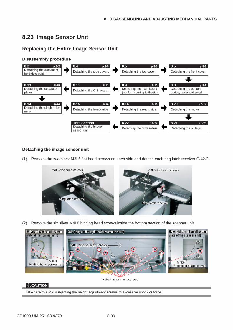
CS1000-UM-251-03-9370 8-30
8. DISASSEMBLING AND ADJUSTING MECHANICAL PARTS
8.23 Image Sensor Unit
Replacing the Entire Image Sensor Unit
Disassembly procedure
Detaching the document hold-down unit
8.2 p.8-2
Detaching the side covers Detaching the top cover Detaching the front cover
Detaching the separator plates
Detaching the main board (not for securing to the jig)
Detaching the bottom plates, large and small
8.4 p.8-5 8.5 p.8-6 8.6 p.8-7
8.13 p.8-15
Detaching the CIS boards
8.11 p.8-13 8.9 p.8-10 8.8 p.8-9
Detaching the image sensor unit
Detaching the drive rollers
This Section 8.22 p.8-27
Detaching the front guide
8.15Detaching the rear guide Detaching the motor
8.16 p.8-19 8.20 p.8-24
Detaching the pulleys
8.21 p.8-26
p.8-18Detaching the pinch roller units
8.14 p.8-16
Detaching the image sensor unit
(1) Remove the two black M3L6 flat head screws on each side and detach each ring latch receiver C-42-2.
M3L6 flat head screws
Ring latch receiver
M3L6 flat head screws
Ring latch receiver
M3L6 flat head screws
Ring latch receiver
M3L6 flat head screws
Ring latch receiver
(2) Remove the six silver M4L8 binding head screws inside the bottom section of the scanner unit.
M4L8 M4L8 binding head screbinding head screwsws
M4L8 M4L8 binding head screbinding head screwsws
M4L8 binding head screM4L8 binding head screwsws
Hole(left-hand small bottom Hole(left-hand small bottom plate of the scanner unit)
Hole (large bottom plate of the scanner unit)Hole (large bottom plate of the scanner unit) Hole (right-hand small bottom Hole (right-hand small bottom plate of the scanner unit)
M4L8 binding head screws
M4L8 binding head screws
M4L8 binding head screws
Hole(left-hand small bottom plate of the scanner unit)
Hole (large bottom plate of the scanner unit) Hole (right-hand small bottom plate of the scanner unit)
Height adjustment screws
CAUTION
Take care to avoid subjecting the height adjustment screws to excessive shock or force.
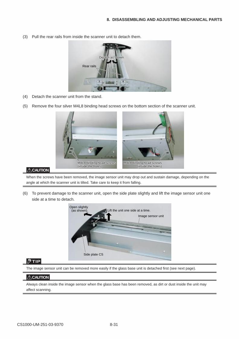
CS1000-UM-251-03-9370 8-31
8. DISASSEMBLING AND ADJUSTING MECHANICAL PARTS
(3) Pull the rear rails from inside the scanner unit to detach them.
Rear rails
Detach as shoDetach as shown.wn.Detach as shown.
(4) Detach the scanner unit from the stand.
(5) Remove the four silver M4L8 binding head screws on the bottom section of the scanner unit.
M4L8 binding head screM4L8 binding head screwsws(inside the holes)(inside the holes)
M4L8 binding head screM4L8 binding head screwsws(inside the holes)
M4L8 binding head screws(inside the holes)
M4L8 binding head screws(inside the holes)
CAUTION
When the screws have been removed, the image sensor unit may drop out and sustain damage, depending on the
angle at which the scanner unit is tilted. Take care to keep it from falling.
(6) To prevent damage to the scanner unit, open the side plate slightly and lift the image sensor unit one
side at a time to detach.
Open slightly(as shown). Lift the unit one side at a time.
Image sensor unit
Side plate CS
TIP
The image sensor unit can be removed more easily if the glass base unit is detached first (see next page).
CAUTION
Always clean inside the image sensor when the glass base has been removed, as dirt or dust inside the unit may
affect scanning.
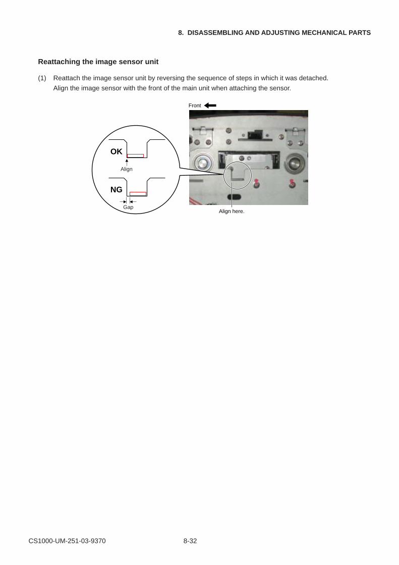
CS1000-UM-251-03-9370 8-32
8. DISASSEMBLING AND ADJUSTING MECHANICAL PARTS
Reattaching the image sensor unit
(1) Reattach the image sensor unit by reversing the sequence of steps in which it was detached.
Align the image sensor with the front of the main unit when attaching the sensor.
Front
Align here.
Align
OK
Gap
NG
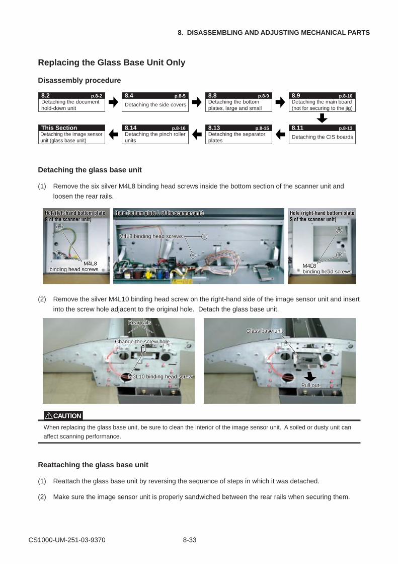
CS1000-UM-251-03-9370 8-33
8. DISASSEMBLING AND ADJUSTING MECHANICAL PARTS
Replacing the Glass Base Unit Only
Disassembly procedure
Detaching the document hold-down unit
8.2 p.8-2
Detaching the side covers
Detaching the separator plates
Detaching the main board (not for securing to the jig)
Detaching the bottom plates, large and small
8.4 p.8-5
8.13 p.8-15
Detaching the CIS boards
8.11 p.8-13
8.9 p.8-108.8 p.8-9
Detaching the image sensor unit (glass base unit)
This SectionDetaching the pinch roller units
8.14 p.8-16
Detaching the glass base unit
(1) Remove the six silver M4L8 binding head screws inside the bottom section of the scanner unit and
loosen the rear rails.
M4L8 M4L8 binding head screws
M4L8 M4L8 binding head screwsbinding head screws
M4L8 binding head screwsM4L8 binding head screws
Hole(left-hand bottom plate Hole(left-hand bottom plate S of the scanner unit)
Hole (bottom plate L of the scanner unit)Hole (bottom plate L of the scanner unit) Hole (right-hand bottom plate Hole (right-hand bottom plate S of the scanner unit)
M4L8 binding head screws
M4L8 binding head screws
M4L8 binding head screws
Hole(left-hand bottom plate S of the scanner unit)
Hole (bottom plate L of the scanner unit) Hole (right-hand bottom plate S of the scanner unit)
(2) Remove the silver M4L10 binding head screw on the right-hand side of the image sensor unit and insert
into the screw hole adjacent to the original hole. Detach the glass base unit.
M3L10 binding head screM3L10 binding head screw
Change the screw holew hole.
Pull out.
Glass base unitGlass base unit
Rear rRear rails
M3L10 binding head screw
Change the screw hole.
Pull out.
Glass base unit
Rear rails
CAUTION
When replacing the glass base unit, be sure to clean the interior of the image sensor unit. A soiled or dusty unit can
affect scanning performance.
Reattaching the glass base unit
(1) Reattach the glass base unit by reversing the sequence of steps in which it was detached.
(2) Make sure the image sensor unit is properly sandwiched between the rear rails when securing them.
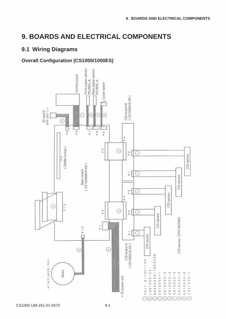
CS1000-UM-251-01-9370 9-1
9. BOARDS AND ELECTRICAL COMPONENTS
9. BOARDS AND ELECTRICAL COMPONENTS
9.1 Wiring Diagrams
Overall Configuration (CS1000/1000ES)
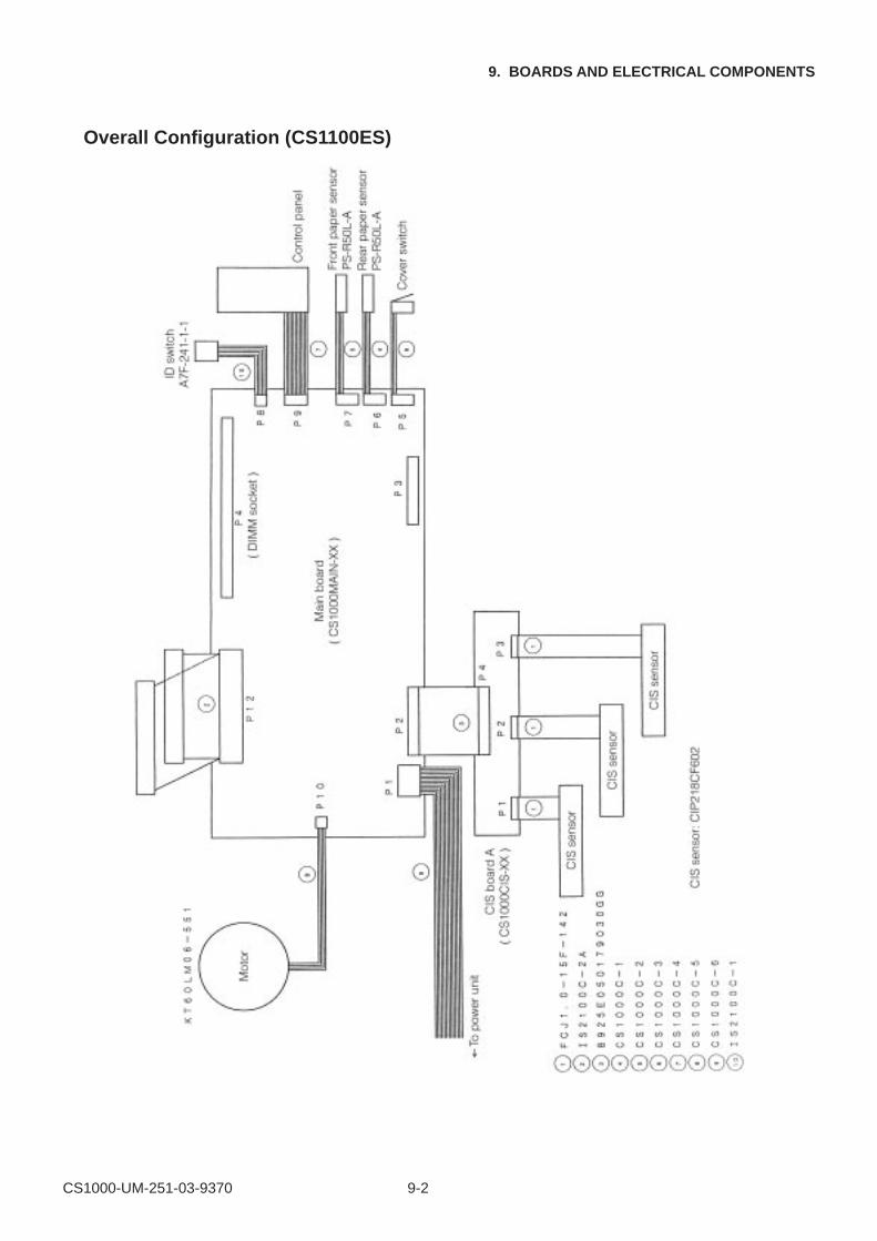
CS1000-UM-251-03-9370 9-2
9. BOARDS AND ELECTRICAL COMPONENTS
Overall Configuration (CS1100ES)
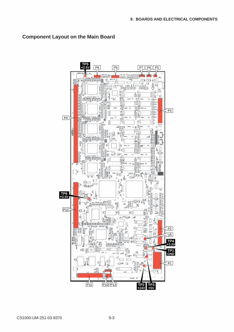
CS1000-UM-251-03-9370 9-3
9. BOARDS AND ELECTRICAL COMPONENTS
Component Layout on the Main Board
P8TP5
+2.5V P9 P6
P3
P5P7
P4
P12
P11 P10 P13 TP3+5V
TP2+24V
TP6+2.5V
P2
U5
P1
TP1GND
TP4+3.3V
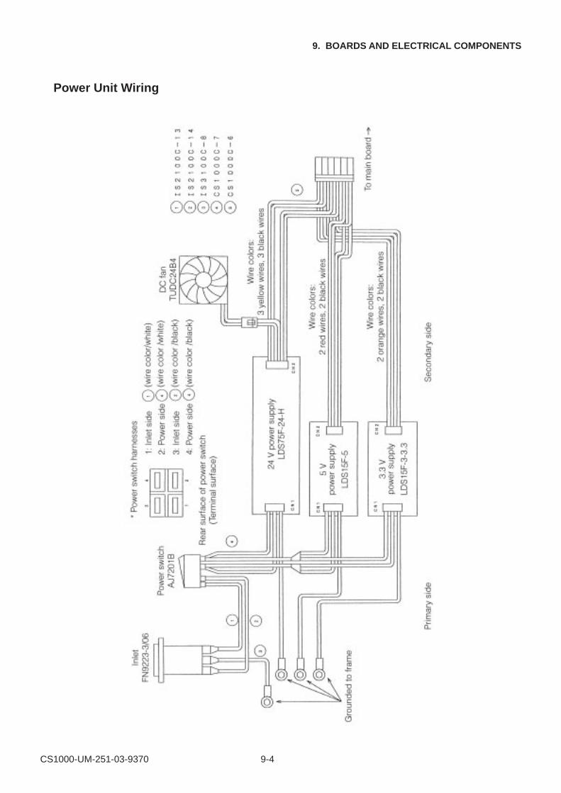
CS1000-UM-251-03-9370 9-4
9. BOARDS AND ELECTRICAL COMPONENTS
Power Unit Wiring

CS1000-UM-251-03-9370 9-5
9. BOARDS AND ELECTRICAL COMPONENTS
9.2 Power Supply Unit
1. Checking Voltage Levels
(1) Turn off the power for the scanner unit.
(2) Detach the connector (CN2) from the power board before checking voltage levels.
(3) Turn on the power for the scanner unit and check voltage levels between the pins listed below.
CAUTION
When making measurements, take care to prevent shorting the ground and output terminals.
The output voltage levels and permissible ranges are given below.
3.3 V power supply (LDS15F-3-3.3)
When checking for +3.3 V, use Pin No.1 or 2 as the ground terminal.
5 V power supply (LDS15F-5)
When checking for +5 V, use Pin No.1 or 2 as the ground terminal.
24 V power supply (LDS75F-24-H)
When checking for +24 V, use any of Pin Numbers 1 through 3 as the ground terminal.
Pin No. Output voltage Permissible range
1 +0V
2 +0V
3 +3.3V +3.25V to +3.35V
4 +3.3V +3.25V to +3.35V
Pin No. Output voltage Permissible range
1 +0V
2 +0V
3 +5V +4.9V to +5.1V
4 +5V +4.9V to +5.1V
Pin No. Output voltage Permissible range
1 +0 V
2 +0 V
3 +0 V
4 +24 V +23.5 V to +24.5 V
5 +24 V +23.5 V to +24.5 V
6 +24 V +23.5 V to +24.5 V
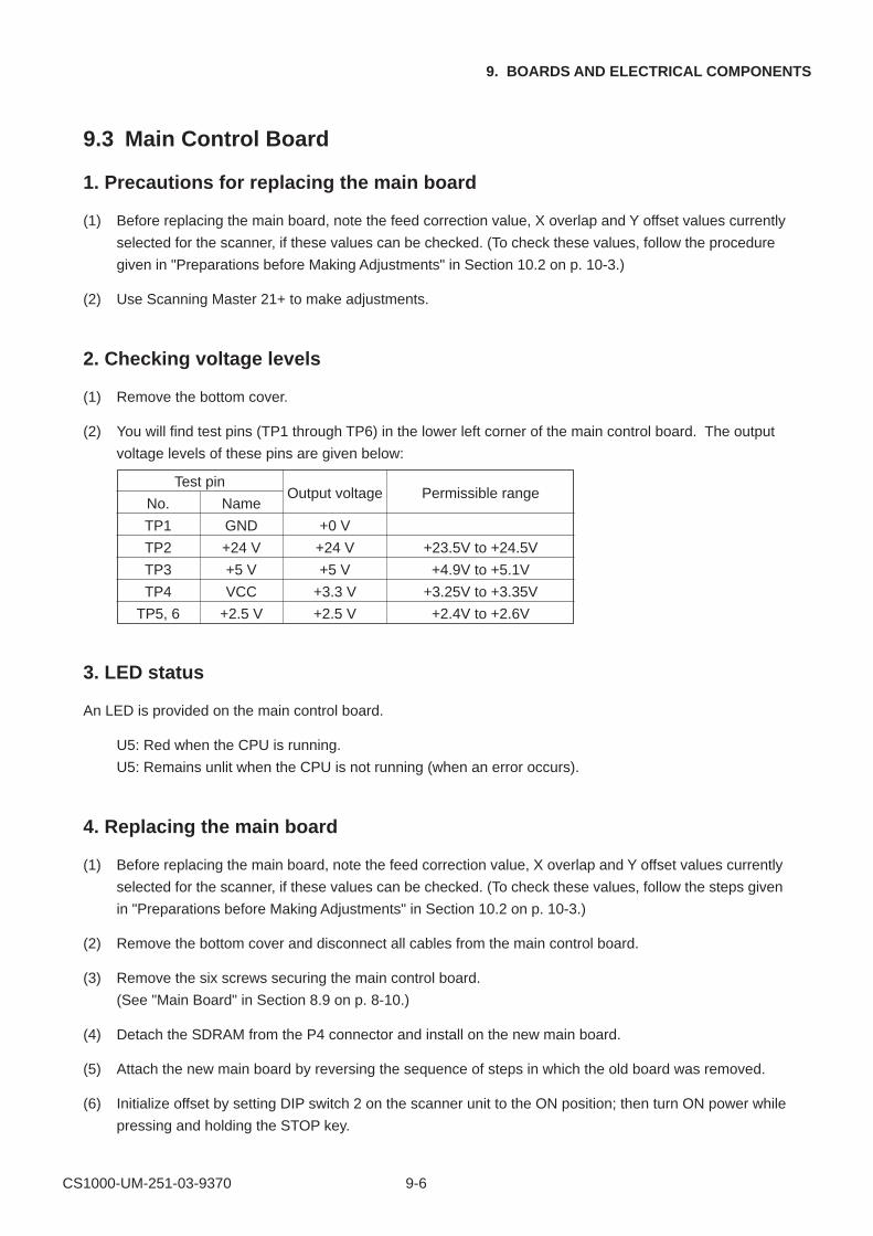
CS1000-UM-251-03-9370 9-6
9. BOARDS AND ELECTRICAL COMPONENTS
9.3 Main Control Board
1. Precautions for replacing the main board
(1) Before replacing the main board, note the feed correction value, X overlap and Y offset values currently
selected for the scanner, if these values can be checked. (To check these values, follow the procedure
given in "Preparations before Making Adjustments" in Section 10.2 on p. 10-3.)
(2) Use Scanning Master 21+ to make adjustments.
2. Checking voltage levels
(1) Remove the bottom cover.
(2) You will find test pins (TP1 through TP6) in the lower left corner of the main control board. The output
voltage levels of these pins are given below:
3. LED status
An LED is provided on the main control board.
U5: Red when the CPU is running.
U5: Remains unlit when the CPU is not running (when an error occurs).
4. Replacing the main board
(1) Before replacing the main board, note the feed correction value, X overlap and Y offset values currently
selected for the scanner, if these values can be checked. (To check these values, follow the steps given
in "Preparations before Making Adjustments" in Section 10.2 on p. 10-3.)
(2) Remove the bottom cover and disconnect all cables from the main control board.
(3) Remove the six screws securing the main control board.
(See "Main Board" in Section 8.9 on p. 8-10.)
(4) Detach the SDRAM from the P4 connector and install on the new main board.
(5) Attach the new main board by reversing the sequence of steps in which the old board was removed.
(6) Initialize offset by setting DIP switch 2 on the scanner unit to the ON position; then turn ON power while
pressing and holding the STOP key.
Test pin
No. NameOutput voltage Permissible range
TP1 GND +0 V
TP2 +24 V +24 V +23.5V to +24.5V
TP3 +5 V +5 V +4.9V to +5.1V
TP4 VCC +3.3 V +3.25V to +3.35V
TP5, 6 +2.5 V +2.5 V +2.4V to +2.6V
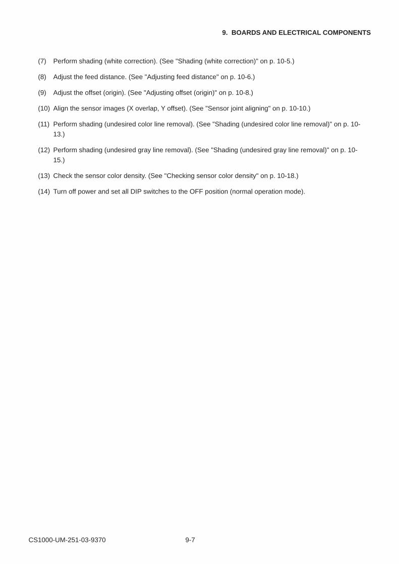
CS1000-UM-251-03-9370 9-7
9. BOARDS AND ELECTRICAL COMPONENTS
(7) Perform shading (white correction). (See "Shading (white correction)" on p. 10-5.)
(8) Adjust the feed distance. (See "Adjusting feed distance" on p. 10-6.)
(9) Adjust the offset (origin). (See "Adjusting offset (origin)" on p. 10-8.)
(10) Align the sensor images (X overlap, Y offset). (See "Sensor joint aligning" on p. 10-10.)
(11) Perform shading (undesired color line removal). (See "Shading (undesired color line removal)" on p. 10-
13.)
(12) Perform shading (undesired gray line removal). (See "Shading (undesired gray line removal)" on p. 10-
15.)
(13) Check the sensor color density. (See "Checking sensor color density" on p. 10-18.)
(14) Turn off power and set all DIP switches to the OFF position (normal operation mode).
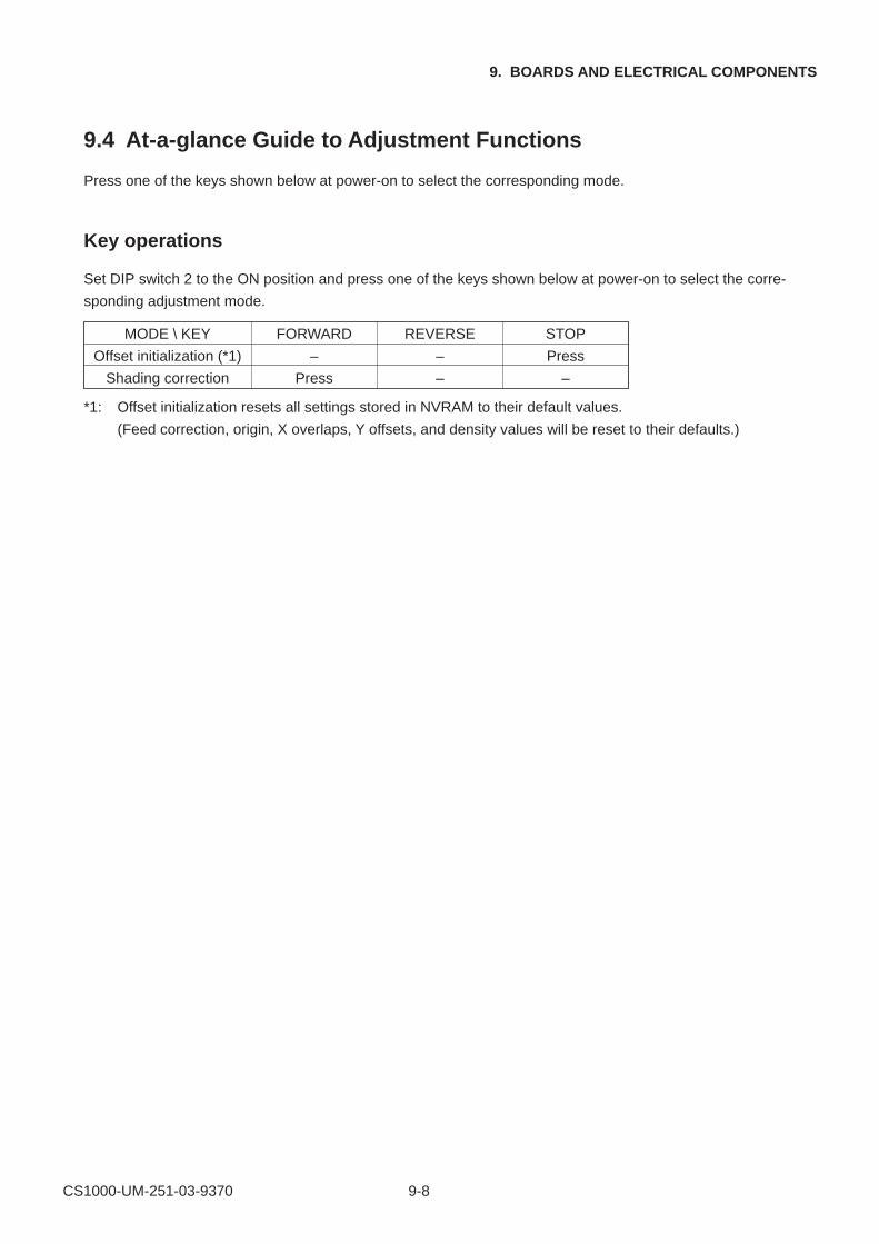
CS1000-UM-251-03-9370 9-8
9. BOARDS AND ELECTRICAL COMPONENTS
9.4 At-a-glance Guide to Adjustment Functions
Press one of the keys shown below at power-on to select the corresponding mode.
Key operations
Set DIP switch 2 to the ON position and press one of the keys shown below at power-on to select the corre-
sponding adjustment mode.
*1: Offset initialization resets all settings stored in NVRAM to their default values.
(Feed correction, origin, X overlaps, Y offsets, and density values will be reset to their defaults.)
MODE \ KEY FORWARD REVERSE STOP
Offset initialization (*1) – – Press
Shading correction Press – –

CS1000-UM-251-03-9370 9-9
9. BOARDS AND ELECTRICAL COMPONENTS
9.5 Downloading the Boot Program
The flash memory of a new main control board has no data stored in it. For this reason, you need to down-
load the boot program from EPROM to flash memory. This makes it possible for the SCSI interface to
perform basic operations. However, note that the flash memory provided on the main board for maintenance
purposes contains the boot program. Thus, you do not need to download the program.
1. Items required to download the boot program
• CS1000 boot ROMs (ODD, EVEN): EPROMs with CS1000INSTXX programs stored
• CS1000 scanner
• CS1000 ROM jigs (used also for the IS3100)
2. Procedure
(1) Open the large bottom plate and confirm that the power board and the control panel are connected to
the main control board.
(2) Attach the EVEN and ODD EPROMs respectively to ROM jigs U1 and U2.
(3) Insert them into P11 on the main board.
(4) Turn on the power switch. At this time, program downloading begins automatically.
(5) When the download is complete, the LED on the main board (CS1000MAIN-[ ][ ]) should begin flashing.
When the LED flashes, turn off power.
(6) Detach the ROM jigs and close the large bottom plate.

CS1000-UM-251-03-9370 9-10
9. BOARDS AND ELECTRICAL COMPONENTS
9.6 Downloading Firmware
This section describes how to download firmware (system programs) via the SCSI interface to the flash
memory provided on the main board, to which the boot program has been downloaded.
1. Items required to download firmware
• CS1000.X file
• CS1000 scanner
• PC (Windows 95 or 98 and an operating environment that provides SCSI compatibility)
• OPS112 (Scanning Master 21+ Ver 3.01 or later)
• SCSI interface cable
2. Procedure
To update the firmware, follow steps (1) to (7).
To download firmware for a new main board, follow steps (8) and (9).
(1) Attach the main board to the CS1000 and use the SCSI cable to connect the CS1000 and PC.
(2) Set DIP switches 1, 2, and 3 to the ON positions and switch on power for the CS1000.
(3) Turn on power for your PC and start OPS112.
(4) When OPS112 starts, follow the steps given below to download the firmware.
1. Access the "Help" menu and select "About." At this time, a dialog box will appear.
2. Point to the icon in the window and click while pressing and holding the "Ctrl" key.
3. Click the "OK" button while pressing and holding the "Shift" key. This makes the status available for
adjustment.
4. Select "Adjust Scanner" from the "Tools" menu to display the Adjust Scanner window.
5. Select "Update Scanner/Firmware" to display the Download dialog box.
(5) Insert the floppy disk containing the firmware (filename: CS1000.X) into the floppy disk drive, click the
"View" button on the Download dialog box, select the floppy disk, and click the "OK" button.
(6) Click the "Start" button to begin downloading.
(7) After the download is complete, a message will appear. At this time, all the panel control LEDs on the
scanner should start flashing simultaneously.
After confirming the download, set all the DIP switches to "OFF," and then switch off power.
(8) When the download is complete, a message will appear. At this time, all panel control LEDs on the
scanner should start flashing at the same time.
After confirming this, turn off power and set DIP switches 1 and 3 to the OFF positions. Switch on
power again while pressing and holding the "STOP" key on the control panel.
Initialization is complete when the "POWER" LED lights up by itself, followed by the "ERROR" LED, and
then the "ERROR" LED will then go out.
(9) Next, set DIP switch 2 to the OFF position and switch on power once again for initialization to take
effect.
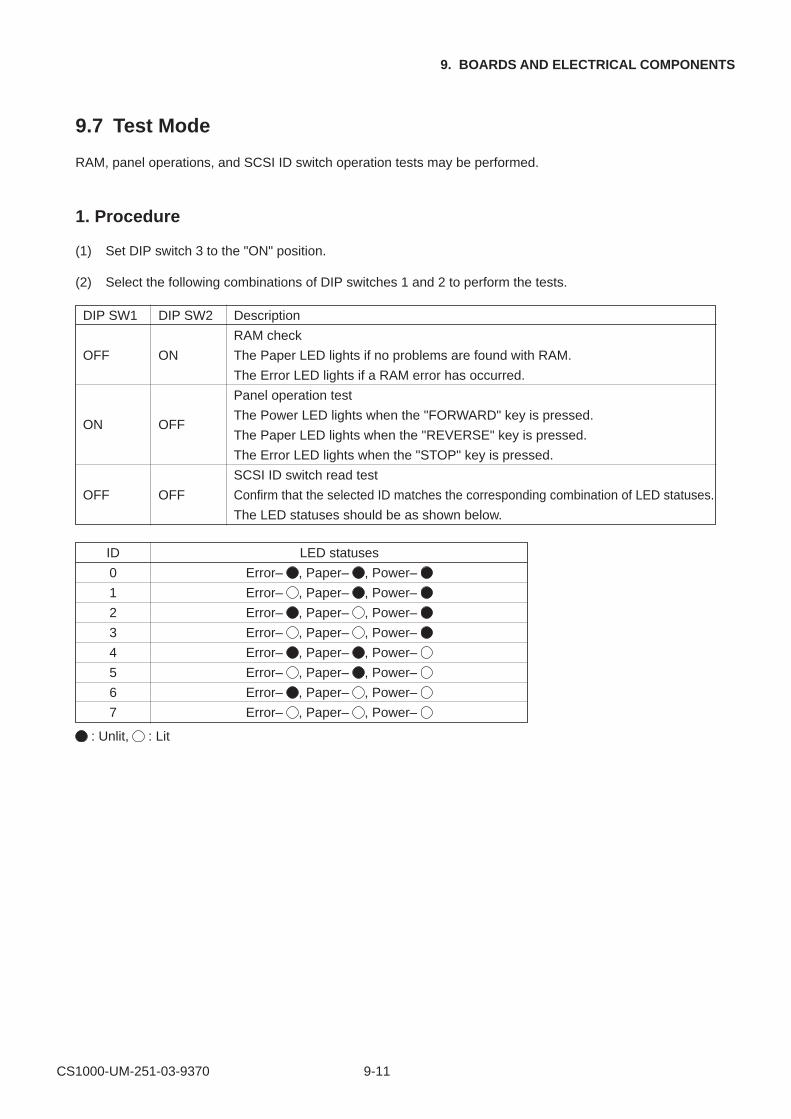
CS1000-UM-251-03-9370 9-11
9. BOARDS AND ELECTRICAL COMPONENTS
DIP SW1 DIP SW2 Description
RAM check
OFF ON The Paper LED lights if no problems are found with RAM.
The Error LED lights if a RAM error has occurred.
Panel operation test
ON OFFThe Power LED lights when the "FORWARD" key is pressed.
The Paper LED lights when the "REVERSE" key is pressed.
The Error LED lights when the "STOP" key is pressed.
SCSI ID switch read test
OFF OFF Confirm that the selected ID matches the corresponding combination of LED statuses.
The LED statuses should be as shown below.
ID LED statuses
0 Error– , Paper– , Power–
1 Error– , Paper– , Power–
2 Error– , Paper– , Power–
3 Error– , Paper– , Power–
4 Error– , Paper– , Power–
5 Error– , Paper– , Power–
6 Error– , Paper– , Power–
7 Error– , Paper– , Power–
: Unlit, : Lit
9.7 Test Mode
RAM, panel operations, and SCSI ID switch operation tests may be performed.
1. Procedure
(1) Set DIP switch 3 to the "ON" position.
(2) Select the following combinations of DIP switches 1 and 2 to perform the tests.
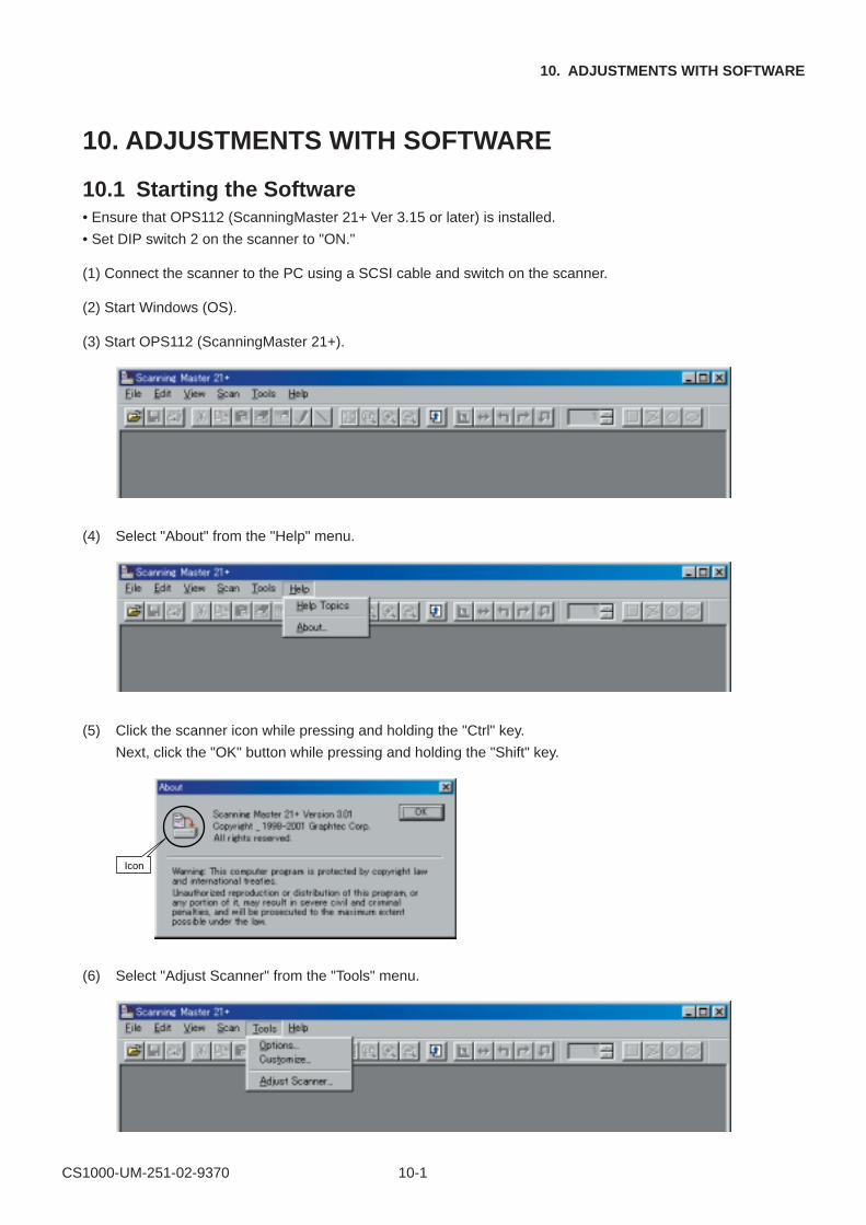
CS1000-UM-251-02-9370 10-1
10. ADJUSTMENTS WITH SOFTWARE
10. ADJUSTMENTS WITH SOFTWARE
10.1 Starting the Software• Ensure that OPS112 (ScanningMaster 21+ Ver 3.15 or later) is installed.
• Set DIP switch 2 on the scanner to "ON."
(1) Connect the scanner to the PC using a SCSI cable and switch on the scanner.
(2) Start Windows (OS).
(3) Start OPS112 (ScanningMaster 21+).
(4) Select "About" from the "Help" menu.
(5) Click the scanner icon while pressing and holding the "Ctrl" key.
Next, click the "OK" button while pressing and holding the "Shift" key.
Icon
(6) Select "Adjust Scanner" from the "Tools" menu.
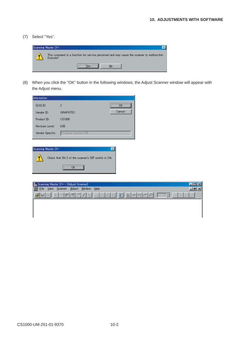
CS1000-UM-251-01-9370 10-2
10. ADJUSTMENTS WITH SOFTWARE
(7) Select "Yes".
(8) When you click the "OK" button in the following windows, the Adjust Scanner window will appear with
the Adjust menu.
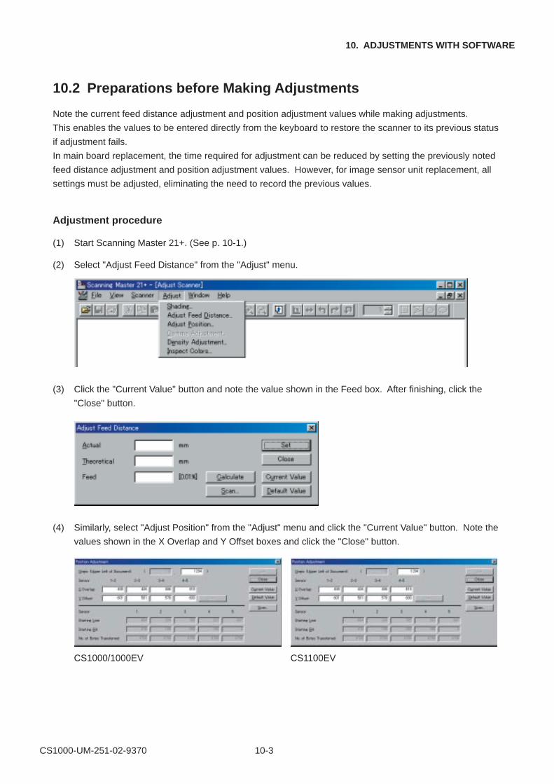
CS1000-UM-251-02-9370 10-3
10. ADJUSTMENTS WITH SOFTWARE
10.2 Preparations before Making Adjustments
Note the current feed distance adjustment and position adjustment values while making adjustments.
This enables the values to be entered directly from the keyboard to restore the scanner to its previous status
if adjustment fails.
In main board replacement, the time required for adjustment can be reduced by setting the previously noted
feed distance adjustment and position adjustment values. However, for image sensor unit replacement, all
settings must be adjusted, eliminating the need to record the previous values.
Adjustment procedure
(1) Start Scanning Master 21+. (See p. 10-1.)
(2) Select "Adjust Feed Distance" from the "Adjust" menu.
(3) Click the "Current Value" button and note the value shown in the Feed box. After finishing, click the
"Close" button.
(4) Similarly, select "Adjust Position" from the "Adjust" menu and click the "Current Value" button. Note the
values shown in the X Overlap and Y Offset boxes and click the "Close" button.
CS1000/1000EV CS1100EV
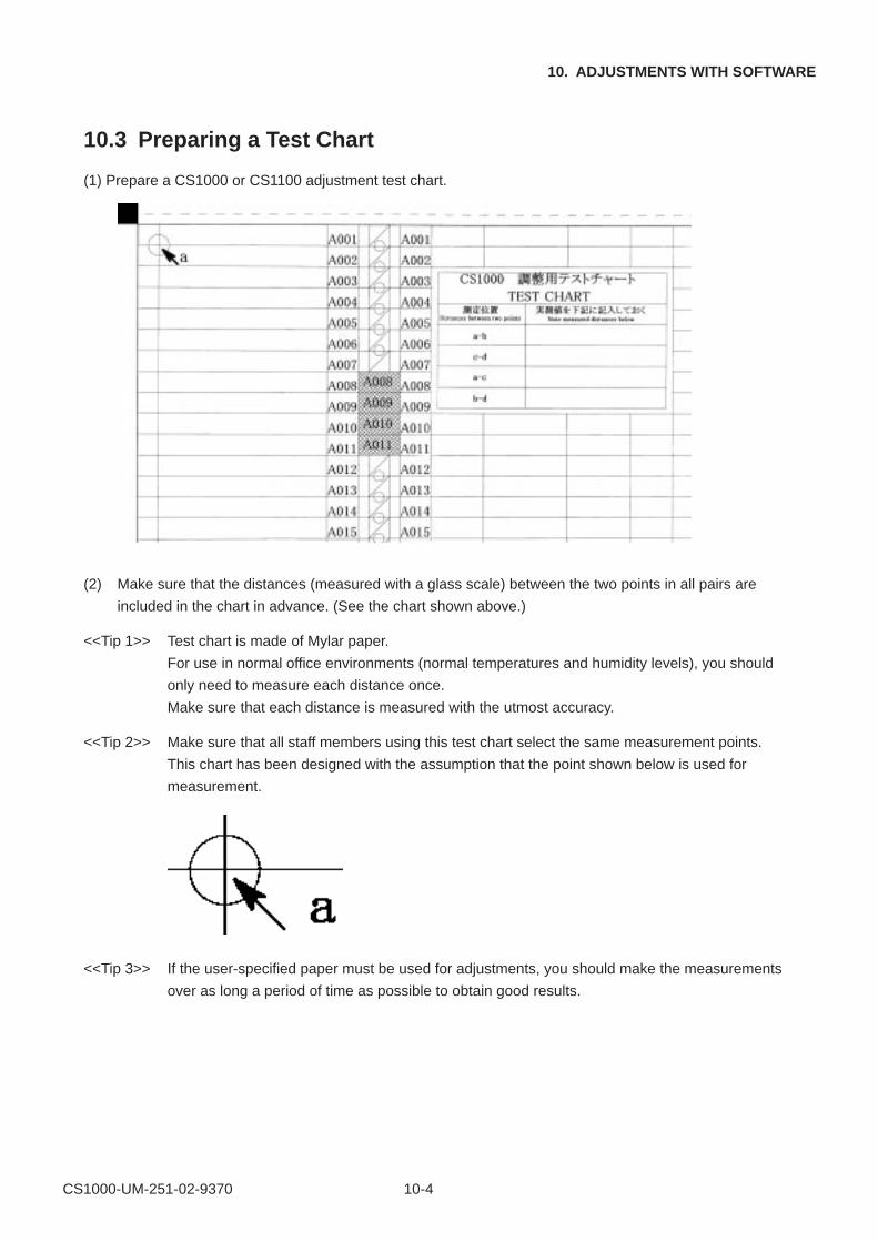
CS1000-UM-251-02-9370 10-4
10. ADJUSTMENTS WITH SOFTWARE
10.3 Preparing a Test Chart
(1) Prepare a CS1000 or CS1100 adjustment test chart.
(2) Make sure that the distances (measured with a glass scale) between the two points in all pairs are
included in the chart in advance. (See the chart shown above.)
<<Tip 1>> Test chart is made of Mylar paper.
For use in normal office environments (normal temperatures and humidity levels), you should
only need to measure each distance once.
Make sure that each distance is measured with the utmost accuracy.
<<Tip 2>> Make sure that all staff members using this test chart select the same measurement points.
This chart has been designed with the assumption that the point shown below is used for
measurement.
<<Tip 3>> If the user-specified paper must be used for adjustments, you should make the measurements
over as long a period of time as possible to obtain good results.
CS1000-UM-251-02-9370 10-5
10. ADJUSTMENTS WITH SOFTWARE
10.4 Making Adjustments
Always follow the sequence given below when making adjustments.
1. Shading (white correction)
2. Feed distance adjustment
3. Position adjustment
Offset adjustment
Sensor joint alignment
4. Shading (undesired color line removal)
5. Shading (undesired gray line removal)
1. Shading (white correction)
(1) Prepare a shading paper (large format). For the CS1100EV, use the small-format shading paper. Clean
the scanner glass, document table, and document hold-down unit.
(2) Switch on the scanner, place the right-hand side of the shading paper against the edge of the main unit
control panel, and press the "FORWARD" key. Continue pressing the "FORWARD" key until the front
side of the paper is positioned so that it protrudes slightly from the rear of the scanner. Then turn off the
scanner.
CHECKPOINT
Position the shading paper with the glossy side facing up.
(3) Confirm that DIP switch "2" is set to the "ON" position.
(4) Turn on the scanner while pressing and holding the "FORWARD" button on the control panel.
Hold down the button until only the "POWER" LED on the panel lights.
CHECKPOINT
The "ERROR" and "PAPER" LEDs alternately flash for 8 minutes during shading.
Later, the "ERROR" LED will light several times. (Period of time required for shading: approximately 20
to 30 minutes)
(5) All LEDs flash when all shading data has been written.
CHECKPOINT
The paper will move several times during shading. This is perfectly normal.
(6) Turn off the scanner once, then turn it on again.
(7) Press the "REVERSE" button to eject the shading paper.
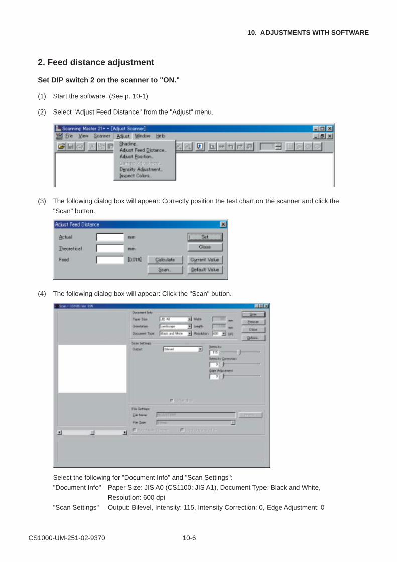
CS1000-UM-251-02-9370 10-6
10. ADJUSTMENTS WITH SOFTWARE
2. Feed distance adjustment
Set DIP switch 2 on the scanner to "ON."
(1) Start the software. (See p. 10-1)
(2) Select "Adjust Feed Distance" from the "Adjust" menu.
(3) The following dialog box will appear: Correctly position the test chart on the scanner and click the
"Scan" button.
(4) The following dialog box will appear: Click the "Scan" button.
Select the following for "Document Info" and "Scan Settings":
"Document Info" Paper Size: JIS A0 (CS1100: JIS A1), Document Type: Black and White,
Resolution: 600 dpi
"Scan Settings" Output: Bilevel, Intensity: 115, Intensity Correction: 0, Edge Adjustment: 0
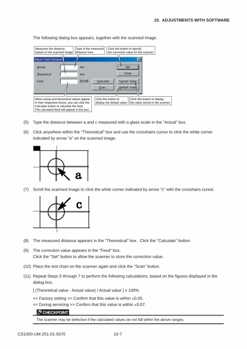
CS1000-UM-251-01-9370 10-7
10. ADJUSTMENTS WITH SOFTWARE
The following dialog box appears, together with the scanned image.
Measures the distance, based on the scanned image
When actual and theoretical values appear in their respective boxes, you can click the Calculate button to calculate the feed. The calculated feed will appear in this box.
Click this button to specify the correction value for the scanner.
Click this button to display the value stored in the scanner.
Click this button to display the default value.
Type in the measured distance here.
(5) Type the distance between a and c measured with a glass scale in the "Actual" box.
(6) Click anywhere within the "Theoretical" box and use the crosshairs cursor to click the white corner
indicated by arrow "a" on the scanned image.
(7) Scroll the scanned image to click the white corner indicated by arrow "c" with the crosshairs cursor.
(8) The measured distance appears in the "Theoretical" box. Click the "Calculate" button.
(9) The correction value appears in the "Feed" box.
Click the "Set" button to allow the scanner to store the correction value.
(10) Place the test chart on the scanner again and click the "Scan" button.
(11) Repeat Steps 5 through 7 to perform the following calculations, based on the figures displayed in the
dialog box.
[ (Theoretical value - Actual value) / Actual value ] x 100%
<< Factory setting >> Confirm that this value is within ±0.05.
<< During servicing >> Confirm that this value is within ±0.07.
CHECKPOINT
The scanner may be defective if the calculated values do not fall within the above ranges.
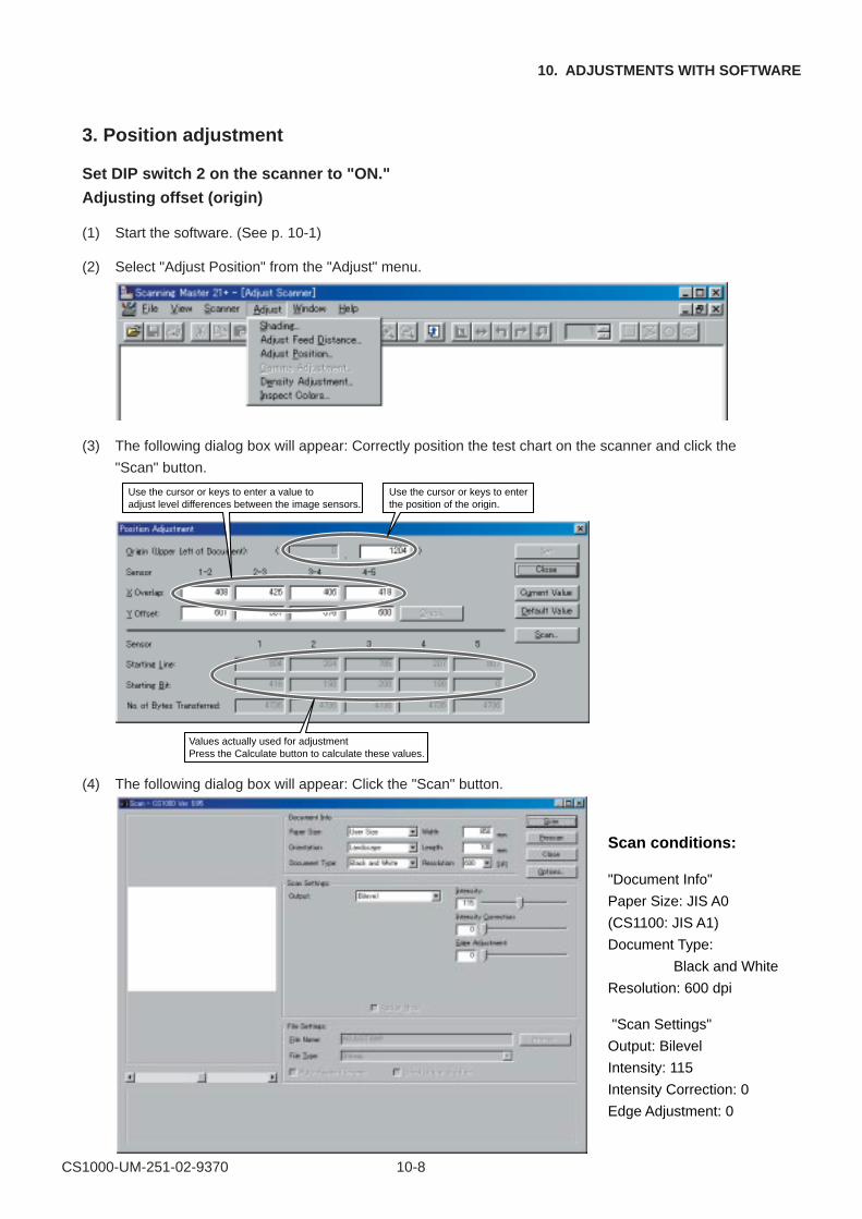
CS1000-UM-251-02-9370 10-8
10. ADJUSTMENTS WITH SOFTWARE
3. Position adjustment
Set DIP switch 2 on the scanner to "ON."
Adjusting offset (origin)
(1) Start the software. (See p. 10-1)
(2) Select "Adjust Position" from the "Adjust" menu.
(3) The following dialog box will appear: Correctly position the test chart on the scanner and click the
"Scan" button.
Use the cursor or keys to enter a value to adjust level differences between the image sensors.
Use the cursor or keys to enter the position of the origin.
Values actually used for adjustmentPress the Calculate button to calculate these values.
(4) The following dialog box will appear: Click the "Scan" button.
Scan conditions:
"Document Info"
Paper Size: JIS A0
(CS1100: JIS A1)
Document Type:
Black and White
Resolution: 600 dpi
"Scan Settings"
Output: Bilevel
Intensity: 115
Intensity Correction: 0
Edge Adjustment: 0
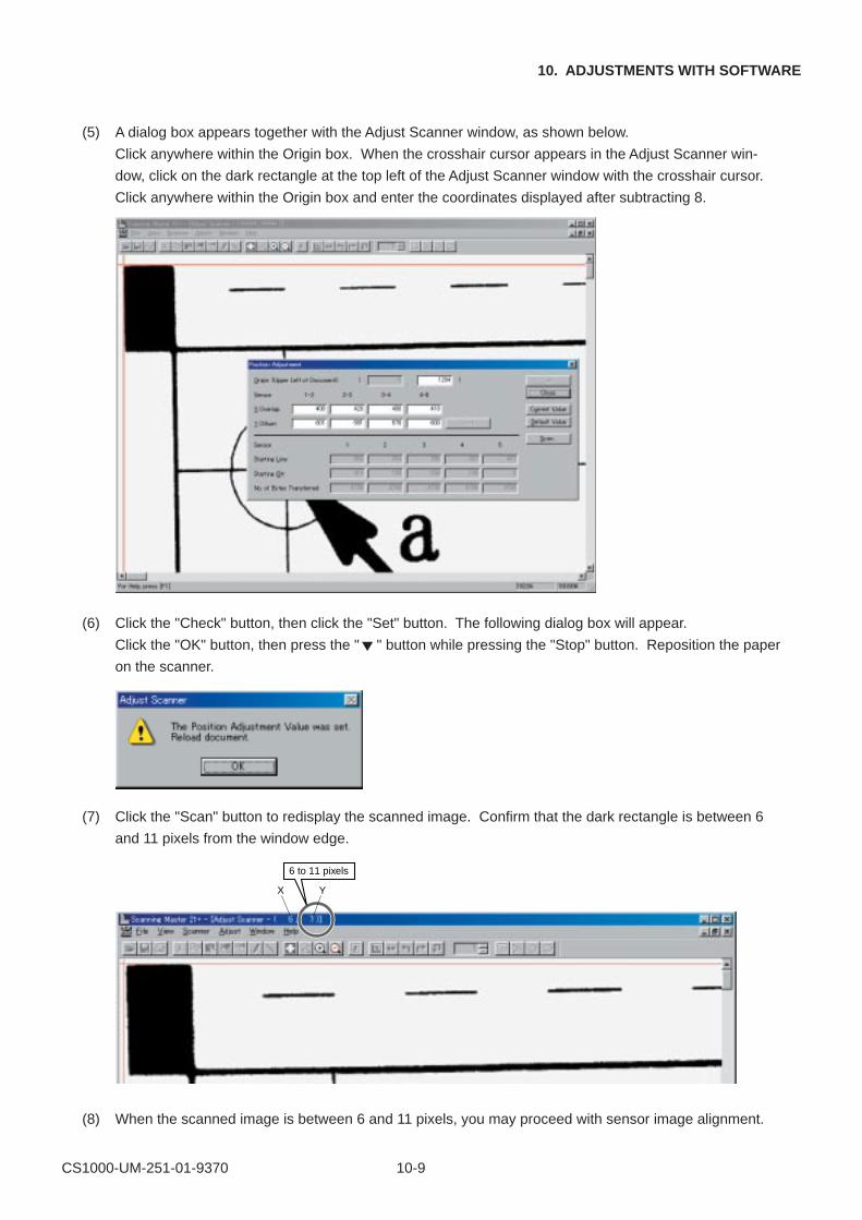
CS1000-UM-251-01-9370 10-9
10. ADJUSTMENTS WITH SOFTWARE
(5) A dialog box appears together with the Adjust Scanner window, as shown below.
Click anywhere within the Origin box. When the crosshair cursor appears in the Adjust Scanner win-
dow, click on the dark rectangle at the top left of the Adjust Scanner window with the crosshair cursor.
Click anywhere within the Origin box and enter the coordinates displayed after subtracting 8.
(6) Click the "Check" button, then click the "Set" button. The following dialog box will appear.
Click the "OK" button, then press the "�" button while pressing the "Stop" button. Reposition the paper
on the scanner.
(7) Click the "Scan" button to redisplay the scanned image. Confirm that the dark rectangle is between 6
and 11 pixels from the window edge.
6 to 11 pixels
YX
(8) When the scanned image is between 6 and 11 pixels, you may proceed with sensor image alignment.
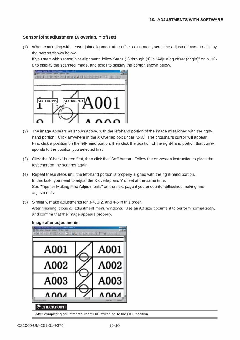
CS1000-UM-251-01-9370 10-10
10. ADJUSTMENTS WITH SOFTWARE
Sensor joint adjustment (X overlap, Y offset)
(1) When continuing with sensor joint alignment after offset adjustment, scroll the adjusted image to display
the portion shown below.
If you start with sensor joint alignment, follow Steps (1) through (4) in "Adjusting offset (origin)" on p. 10-
8 to display the scanned image, and scroll to display the portion shown below.
Click here first. Click here next.
(2) The image appears as shown above, with the left-hand portion of the image misaligned with the right-
hand portion. Click anywhere in the X Overlap box under "2-3." The crosshairs cursor will appear.
First click a position on the left-hand portion, then click the position of the right-hand portion that corre-
sponds to the position you selected first.
(3) Click the "Check" button first, then click the "Set" button. Follow the on-screen instruction to place the
test chart on the scanner again.
(4) Repeat these steps until the left-hand portion is properly aligned with the right-hand portion.
In this task, you need to adjust the X overlap and Y offset at the same time.
See "Tips for Making Fine Adjustments" on the next page if you encounter difficulties making fine
adjustments.
(5) Similarly, make adjustments for 3-4, 1-2, and 4-5 in this order.
After finishing, close all adjustment menu windows. Use an A0 size document to perform normal scan,
and confirm that the image appears properly.
Image after adjustments
CHECKPOINT
After completing adjustments, reset DIP switch "2" to the OFF position.
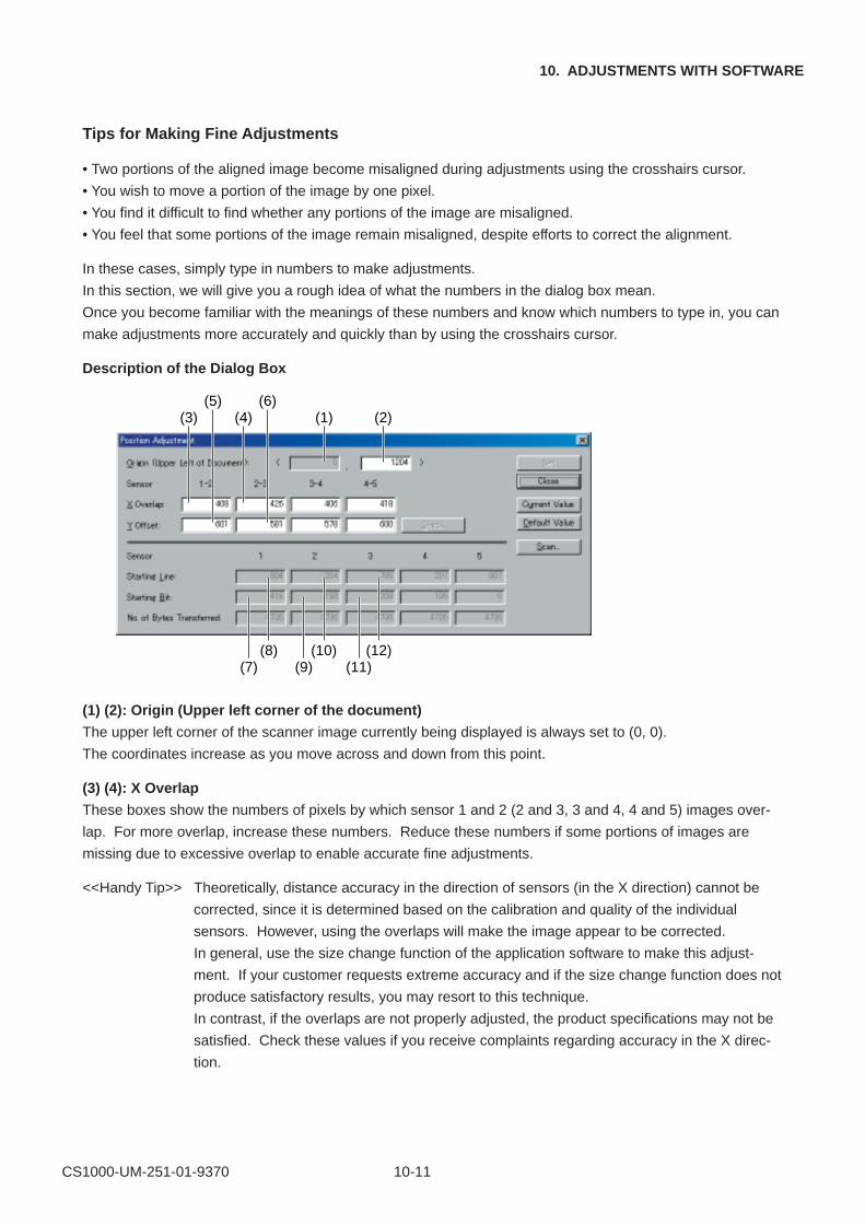
CS1000-UM-251-01-9370 10-11
10. ADJUSTMENTS WITH SOFTWARE
Tips for Making Fine Adjustments
• Two portions of the aligned image become misaligned during adjustments using the crosshairs cursor.
• You wish to move a portion of the image by one pixel.
• You find it difficult to find whether any portions of the image are misaligned.
• You feel that some portions of the image remain misaligned, despite efforts to correct the alignment.
In these cases, simply type in numbers to make adjustments.
In this section, we will give you a rough idea of what the numbers in the dialog box mean.
Once you become familiar with the meanings of these numbers and know which numbers to type in, you can
make adjustments more accurately and quickly than by using the crosshairs cursor.
Description of the Dialog Box
(3) (4) (1) (2)(5) (6)
(7) (9) (11)(8) (10) (12)
(1) (2): Origin (Upper left corner of the document)
The upper left corner of the scanner image currently being displayed is always set to (0, 0).
The coordinates increase as you move across and down from this point.
(3) (4): X Overlap
These boxes show the numbers of pixels by which sensor 1 and 2 (2 and 3, 3 and 4, 4 and 5) images over-
lap. For more overlap, increase these numbers. Reduce these numbers if some portions of images are
missing due to excessive overlap to enable accurate fine adjustments.
<<Handy Tip>> Theoretically, distance accuracy in the direction of sensors (in the X direction) cannot be
corrected, since it is determined based on the calibration and quality of the individual
sensors. However, using the overlaps will make the image appear to be corrected.
In general, use the size change function of the application software to make this adjust-
ment. If your customer requests extreme accuracy and if the size change function does not
produce satisfactory results, you may resort to this technique.
In contrast, if the overlaps are not properly adjusted, the product specifications may not be
satisfied. Check these values if you receive complaints regarding accuracy in the X direc-
tion.
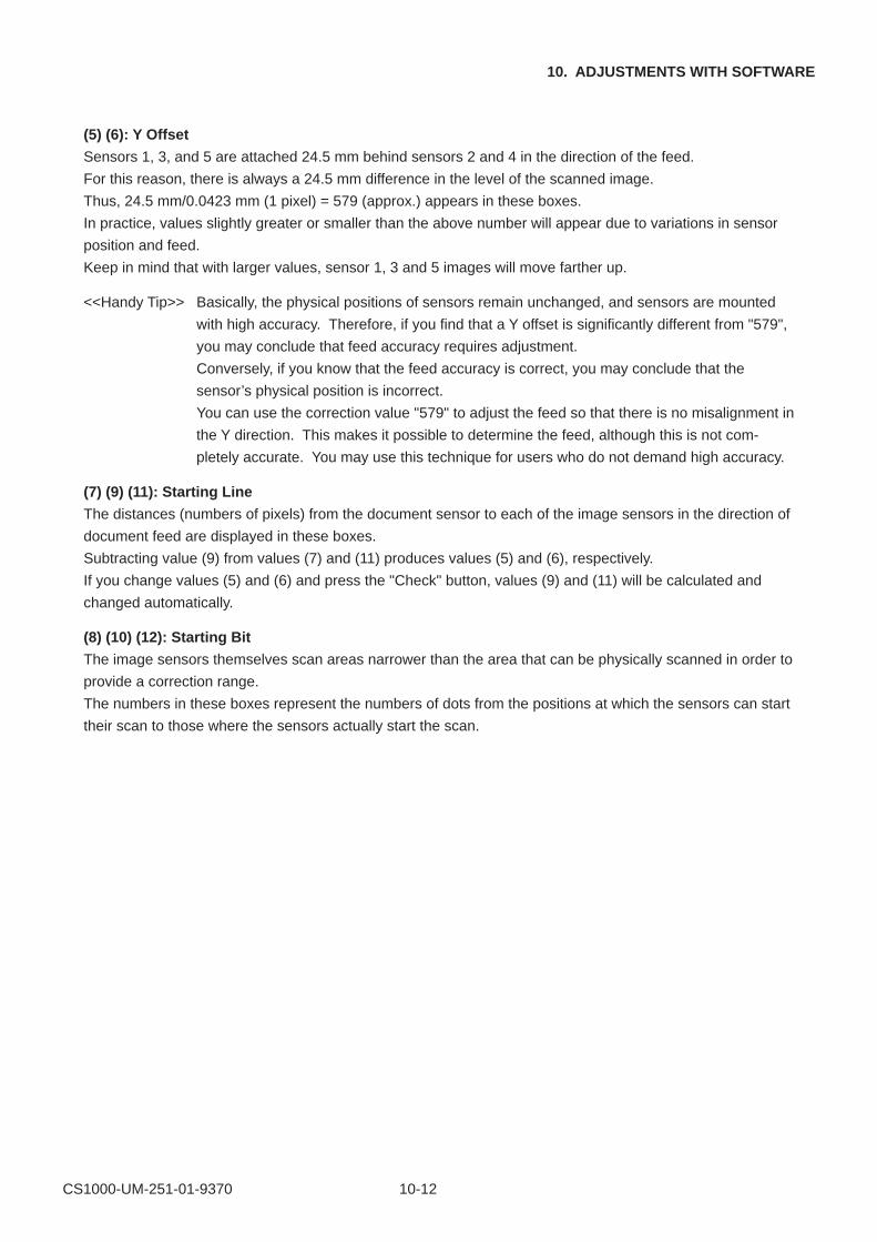
CS1000-UM-251-01-9370 10-12
10. ADJUSTMENTS WITH SOFTWARE
(5) (6): Y Offset
Sensors 1, 3, and 5 are attached 24.5 mm behind sensors 2 and 4 in the direction of the feed.
For this reason, there is always a 24.5 mm difference in the level of the scanned image.
Thus, 24.5 mm/0.0423 mm (1 pixel) = 579 (approx.) appears in these boxes.
In practice, values slightly greater or smaller than the above number will appear due to variations in sensor
position and feed.
Keep in mind that with larger values, sensor 1, 3 and 5 images will move farther up.
<<Handy Tip>> Basically, the physical positions of sensors remain unchanged, and sensors are mounted
with high accuracy. Therefore, if you find that a Y offset is significantly different from "579",
you may conclude that feed accuracy requires adjustment.
Conversely, if you know that the feed accuracy is correct, you may conclude that the
sensor’s physical position is incorrect.
You can use the correction value "579" to adjust the feed so that there is no misalignment in
the Y direction. This makes it possible to determine the feed, although this is not com-
pletely accurate. You may use this technique for users who do not demand high accuracy.
(7) (9) (11): Starting Line
The distances (numbers of pixels) from the document sensor to each of the image sensors in the direction of
document feed are displayed in these boxes.
Subtracting value (9) from values (7) and (11) produces values (5) and (6), respectively.
If you change values (5) and (6) and press the "Check" button, values (9) and (11) will be calculated and
changed automatically.
(8) (10) (12): Starting Bit
The image sensors themselves scan areas narrower than the area that can be physically scanned in order to
provide a correction range.
The numbers in these boxes represent the numbers of dots from the positions at which the sensors can start
their scan to those where the sensors actually start the scan.
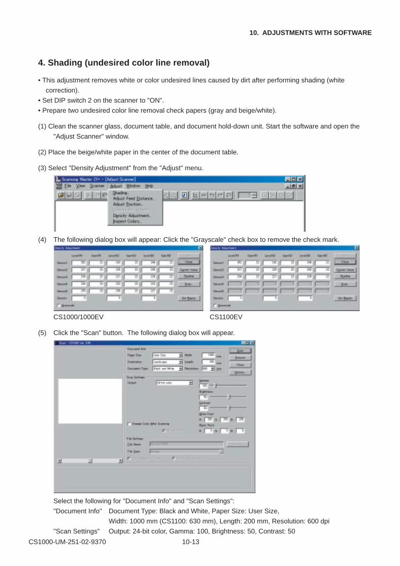
CS1000-UM-251-02-9370 10-13
10. ADJUSTMENTS WITH SOFTWARE
4. Shading (undesired color line removal)
• This adjustment removes white or color undesired lines caused by dirt after performing shading (white
correction).
• Set DIP switch 2 on the scanner to "ON".
• Prepare two undesired color line removal check papers (gray and beige/white).
(1) Clean the scanner glass, document table, and document hold-down unit. Start the software and open the
"Adjust Scanner" window.
(2) Place the beige/white paper in the center of the document table.
(3) Select "Density Adjustment" from the "Adjust" menu.
(4) The following dialog box will appear: Click the "Grayscale" check box to remove the check mark.
CS1000/1000EV CS1100EV
(5) Click the "Scan" button. The following dialog box will appear.
Select the following for "Document Info" and "Scan Settings":
"Document Info" Document Type: Black and White, Paper Size: User Size,
Width: 1000 mm (CS1100: 630 mm), Length: 200 mm, Resolution: 600 dpi
"Scan Settings" Output: 24-bit color, Gamma: 100, Brightness: 50, Contrast: 50
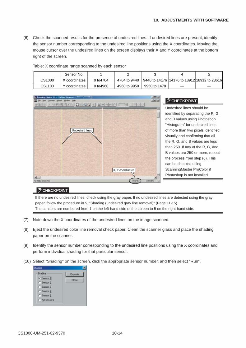
CS1000-UM-251-02-9370 10-14
10. ADJUSTMENTS WITH SOFTWARE
(6) Check the scanned results for the presence of undesired lines. If undesired lines are present, identify
the sensor number corresponding to the undesired line positions using the X coordinates. Moving the
mouse cursor over the undesired lines on the screen displays their X and Y coordinates at the bottom
right of the screen.
Table: X coordinate range scanned by each sensor
CS1000
CS1100
Sensor No.
X coordinates
Y coordinates
1
0 to4704
0 to4960
2
4704 to 9440
4960 to 9950
3
9440 to 14176
9950 to 1478
4
14176 to 18912
–
5
18912 to 23616
–
CHECKPOINT
Undesired lines should be
identified by separating the R, G,
and B values using Photoshop
"Histogram" for undesired lines
of more than two pixels identified
visually and confirming that all
the R, G, and B values are less
than 250. If any of the R, G, and
B values are 250 or more, repeat
the process from step (6). This
can be checked using
ScanningMaster ProColor if
Photoshop is not installed.
CHECKPOINT
If there are no undesired lines, check using the gray paper. If no undesired lines are detected using the gray
paper, follow the procedure in 5. "Shading (undesired gray line removal)" (Page 11-15).
The sensors are numbered from 1 on the left-hand side of the screen to 5 on the right-hand side.
(7) Note down the X coordinates of the undesired lines on the image scanned.
(8) Eject the undesired color line removal check paper. Clean the scanner glass and place the shading
paper on the scanner.
(9) Identify the sensor number corresponding to the undesired line positions using the X coordinates and
perform individual shading for that particular sensor.
(10) Select "Shading" on the screen, click the appropriate sensor number, and then select "Run".
Undesired lines
X, Y coordinates
CS1000-UM-251-02-9370 10-15
10. ADJUSTMENTS WITH SOFTWARE
(11) Once shading is finished, replace the shading paper with the undesired color line removal check paper
and check that the undesired lines have disappeared. If they are no longer present, remove the undes-
ired lines for the other sensors in the same way. The process is complete once the undesired lines for
all sensors have been removed.
(12) If undesired lines are still present, repeat the process from step (6).
(13) Replace with the gray paper and adjust undesired line removal in the same way.
CHECKPOINT
If undesired white lines persist at the same positions even after repeating the undesired line removal procedure
several times, it is possible that the glass is scratched or there is dirt inside the sensor unit (e.g., Selfoc lens
upper section). Check accordingly.
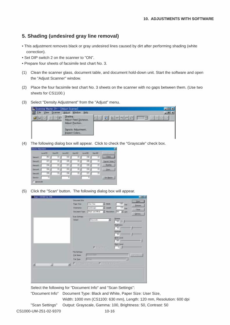
CS1000-UM-251-02-9370 10-16
10. ADJUSTMENTS WITH SOFTWARE
5. Shading (undesired gray line removal)
• This adjustment removes black or gray undesired lines caused by dirt after performing shading (white
correction).
• Set DIP switch 2 on the scanner to "ON".
• Prepare four sheets of facsimile test chart No. 3.
(1) Clean the scanner glass, document table, and document hold-down unit. Start the software and open
the "Adjust Scanner" window.
(2) Place the four facsimile test chart No. 3 sheets on the scanner with no gaps between them. (Use two
sheets for CS1100.)
(3) Select "Density Adjustment" from the "Adjust" menu.
(4) The following dialog box will appear. Click to check the "Grayscale" check box.
(5) Click the "Scan" button. The following dialog box will appear.
Select the following for "Document Info" and "Scan Settings":
"Document Info" Document Type: Black and White, Paper Size: User Size,
Width: 1000 mm (CS1100: 630 mm), Length: 120 mm, Resolution: 600 dpi
"Scan Settings" Output: Grayscale, Gamma: 100, Brightness: 50, Contrast: 50
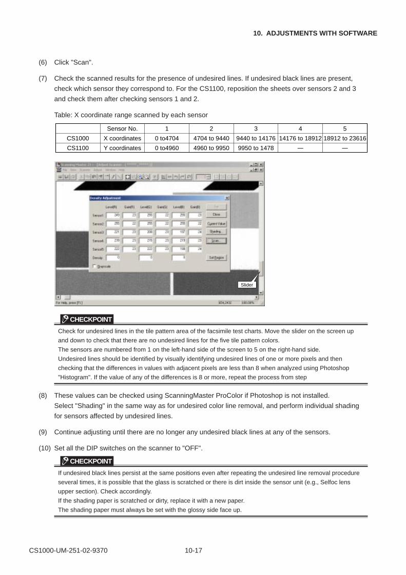
CS1000-UM-251-02-9370 10-17
10. ADJUSTMENTS WITH SOFTWARE
(6) Click "Scan".
(7) Check the scanned results for the presence of undesired lines. If undesired black lines are present,
check which sensor they correspond to. For the CS1100, reposition the sheets over sensors 2 and 3
and check them after checking sensors 1 and 2.
Table: X coordinate range scanned by each sensor
CS1000
CS1100
Sensor No.
X coordinates
Y coordinates
1
0 to4704
0 to4960
2
4704 to 9440
4960 to 9950
3
9440 to 14176
9950 to 1478
4
14176 to 18912
–
5
18912 to 23616
–
Slider
CHECKPOINT
Check for undesired lines in the tile pattern area of the facsimile test charts. Move the slider on the screen up
and down to check that there are no undesired lines for the five tile pattern colors.
The sensors are numbered from 1 on the left-hand side of the screen to 5 on the right-hand side.
Undesired lines should be identified by visually identifying undesired lines of one or more pixels and then
checking that the differences in values with adjacent pixels are less than 8 when analyzed using Photoshop
"Histogram". If the value of any of the differences is 8 or more, repeat the process from step
(8) These values can be checked using ScanningMaster ProColor if Photoshop is not installed.
Select "Shading" in the same way as for undesired color line removal, and perform individual shading
for sensors affected by undesired lines.
(9) Continue adjusting until there are no longer any undesired black lines at any of the sensors.
(10) Set all the DIP switches on the scanner to "OFF".
CHECKPOINT
If undesired black lines persist at the same positions even after repeating the undesired line removal procedure
several times, it is possible that the glass is scratched or there is dirt inside the sensor unit (e.g., Selfoc lens
upper section). Check accordingly.
If the shading paper is scratched or dirty, replace it with a new paper.
The shading paper must always be set with the glossy side face up.
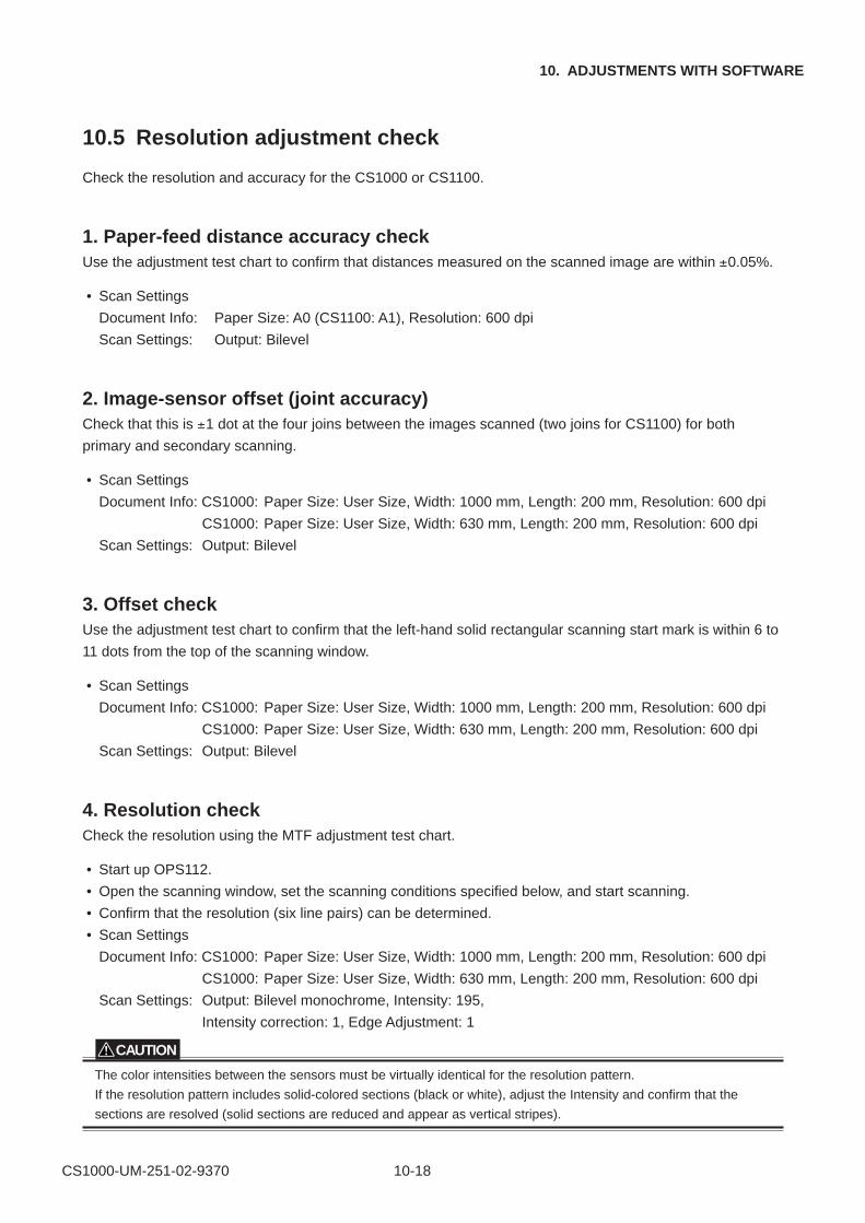
CS1000-UM-251-02-9370 10-18
10. ADJUSTMENTS WITH SOFTWARE
10.5 Resolution adjustment check
Check the resolution and accuracy for the CS1000 or CS1100.
1. Paper-feed distance accuracy checkUse the adjustment test chart to confirm that distances measured on the scanned image are within ±0.05%.
• Scan Settings
Document Info: Paper Size: A0 (CS1100: A1), Resolution: 600 dpi
Scan Settings: Output: Bilevel
2. Image-sensor offset (joint accuracy)Check that this is ±1 dot at the four joins between the images scanned (two joins for CS1100) for both
primary and secondary scanning.
• Scan Settings
Document Info: CS1000: Paper Size: User Size, Width: 1000 mm, Length: 200 mm, Resolution: 600 dpi
CS1000: Paper Size: User Size, Width: 630 mm, Length: 200 mm, Resolution: 600 dpi
Scan Settings: Output: Bilevel
3. Offset checkUse the adjustment test chart to confirm that the left-hand solid rectangular scanning start mark is within 6 to
11 dots from the top of the scanning window.
• Scan Settings
Document Info: CS1000: Paper Size: User Size, Width: 1000 mm, Length: 200 mm, Resolution: 600 dpi
CS1000: Paper Size: User Size, Width: 630 mm, Length: 200 mm, Resolution: 600 dpi
Scan Settings: Output: Bilevel
4. Resolution checkCheck the resolution using the MTF adjustment test chart.
• Start up OPS112.
• Open the scanning window, set the scanning conditions specified below, and start scanning.
• Confirm that the resolution (six line pairs) can be determined.
• Scan Settings
Document Info: CS1000: Paper Size: User Size, Width: 1000 mm, Length: 200 mm, Resolution: 600 dpi
CS1000: Paper Size: User Size, Width: 630 mm, Length: 200 mm, Resolution: 600 dpi
Scan Settings: Output: Bilevel monochrome, Intensity: 195,
Intensity correction: 1, Edge Adjustment: 1
CAUTION
The color intensities between the sensors must be virtually identical for the resolution pattern.
If the resolution pattern includes solid-colored sections (black or white), adjust the Intensity and confirm that the
sections are resolved (solid sections are reduced and appear as vertical stripes).
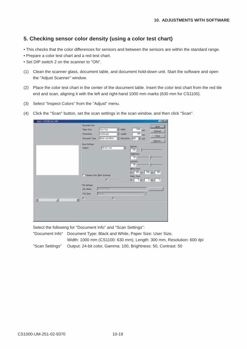
CS1000-UM-251-02-9370 10-19
10. ADJUSTMENTS WITH SOFTWARE
5. Checking sensor color density (using a color test chart)
• This checks that the color differences for sensors and between the sensors are within the standard range.
• Prepare a color test chart and a red test chart.
• Set DIP switch 2 on the scanner to "ON".
(1) Clean the scanner glass, document table, and document hold-down unit. Start the software and open
the "Adjust Scanner" window.
(2) Place the color test chart in the center of the document table. Insert the color test chart from the red tile
end and scan, aligning it with the left and right-hand 1000 mm marks (630 mm for CS1100).
(3) Select "Inspect Colors" from the "Adjust" menu.
(4) Click the "Scan" button, set the scan settings in the scan window, and then click "Scan".
Select the following for "Document Info" and "Scan Settings":
"Document Info" Document Type: Black and White, Paper Size: User Size,
Width: 1000 mm (CS1100: 630 mm), Length: 300 mm, Resolution: 600 dpi
"Scan Settings" Output: 24-bit color, Gamma: 100, Brightness: 50, Contrast: 50
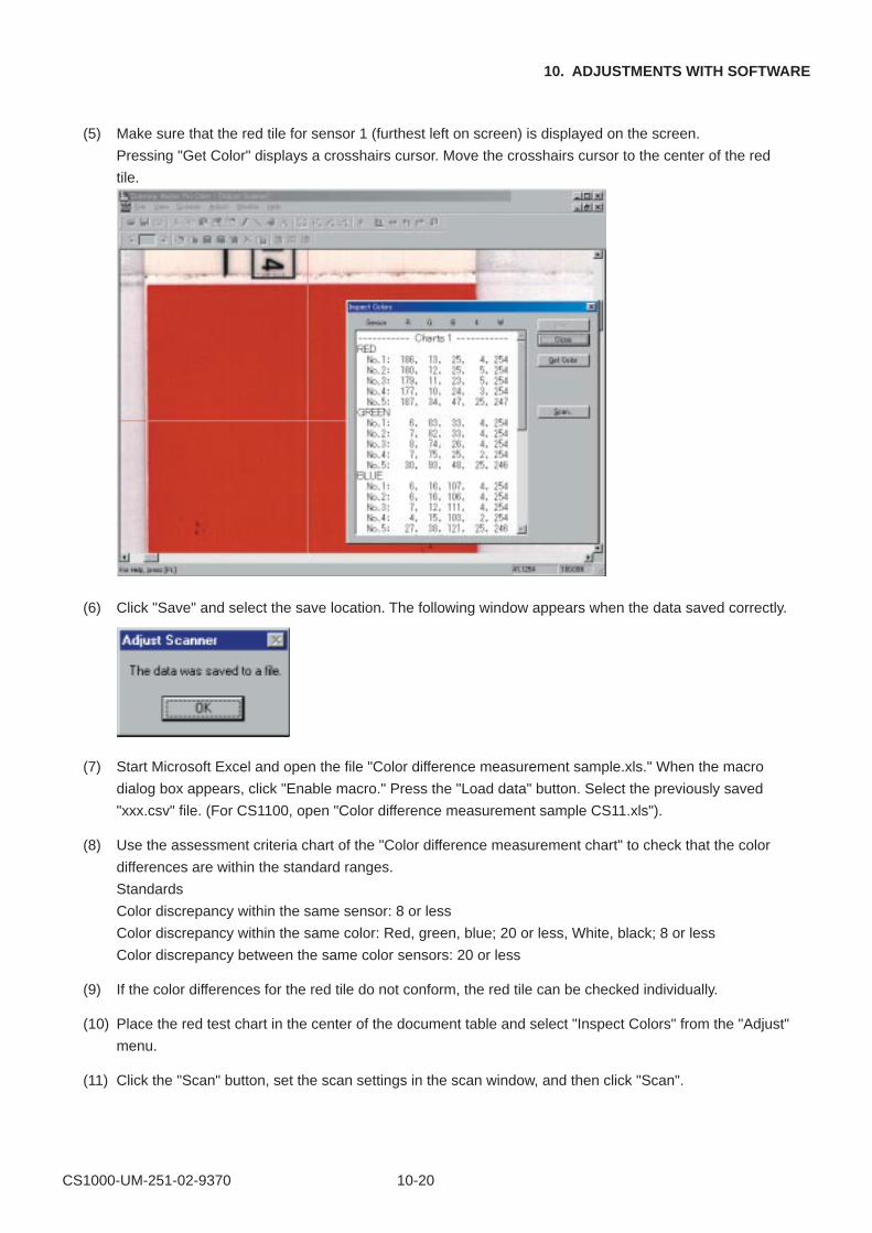
CS1000-UM-251-02-9370 10-20
10. ADJUSTMENTS WITH SOFTWARE
(5) Make sure that the red tile for sensor 1 (furthest left on screen) is displayed on the screen.
Pressing "Get Color" displays a crosshairs cursor. Move the crosshairs cursor to the center of the red
tile.
(6) Click "Save" and select the save location. The following window appears when the data saved correctly.
(7) Start Microsoft Excel and open the file "Color difference measurement sample.xls." When the macro
dialog box appears, click "Enable macro." Press the "Load data" button. Select the previously saved
"xxx.csv" file. (For CS1100, open "Color difference measurement sample CS11.xls").
(8) Use the assessment criteria chart of the "Color difference measurement chart" to check that the color
differences are within the standard ranges.
Standards
Color discrepancy within the same sensor: 8 or less
Color discrepancy within the same color: Red, green, blue; 20 or less, White, black; 8 or less
Color discrepancy between the same color sensors: 20 or less
(9) If the color differences for the red tile do not conform, the red tile can be checked individually.
(10) Place the red test chart in the center of the document table and select "Inspect Colors" from the "Adjust"
menu.
(11) Click the "Scan" button, set the scan settings in the scan window, and then click "Scan".
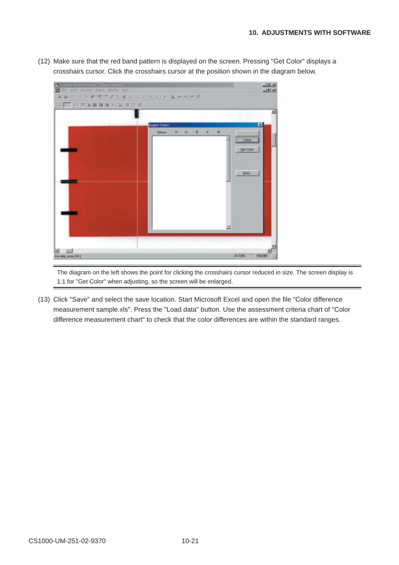
CS1000-UM-251-02-9370 10-21
10. ADJUSTMENTS WITH SOFTWARE
(12) Make sure that the red band pattern is displayed on the screen. Pressing "Get Color" displays a
crosshairs cursor. Click the crosshairs cursor at the position shown in the diagram below.
The diagram on the left shows the point for clicking the crosshairs cursor reduced in size. The screen display is
1:1 for "Get Color" when adjusting, so the screen will be enlarged.
(13) Click "Save" and select the save location. Start Microsoft Excel and open the file "Color difference
measurement sample.xls". Press the "Load data" button. Use the assessment criteria chart of "Color
difference measurement chart" to check that the color differences are within the standard ranges.
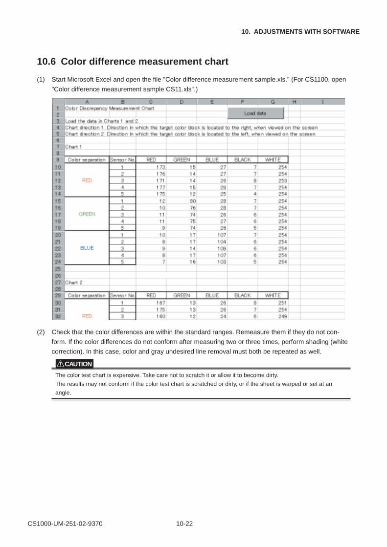
CS1000-UM-251-02-9370 10-22
10. ADJUSTMENTS WITH SOFTWARE
10.6 Color difference measurement chart
(1) Start Microsoft Excel and open the file "Color difference measurement sample.xls." (For CS1100, open
"Color difference measurement sample CS11.xls".)
(2) Check that the color differences are within the standard ranges. Remeasure them if they do not con-
form. If the color differences do not conform after measuring two or three times, perform shading (white
correction). In this case, color and gray undesired line removal must both be repeated as well.
CAUTION
The color test chart is expensive. Take care not to scratch it or allow it to become dirty.
The results may not conform if the color test chart is scratched or dirty, or if the sheet is warped or set at an
angle.
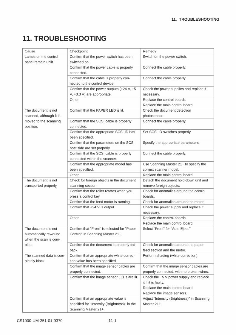
CS1000-UM-251-01-9370 11-1
11. TROUBLESHOOTING
11. TROUBLESHOOTING
Cause
Lamps on the control
panel remain unlit.
The document is not
scanned, although it is
moved to the scanning
position.
The document is not
transported properly.
The document is not
automatically rewound
when the scan is com-
plete.
The scanned data is com-
pletely black.
Remedy
Switch on the power switch.
Connect the cable properly.
Connect the cable properly.
Check the power supplies and replace if
necessary.
Replace the control boards.
Replace the main control board.
Check the document detection
photosensor.
Connect the cable properly.
Set SCSI ID switches properly.
Specify the appropriate parameters.
Connect the cable properly.
Use Scanning Master 21+ to specify the
correct scanner model.
Replace the main control board.
Detach the document hold-down unit and
remove foreign objects.
Check for anomalies around the control
boards.
Check for anomalies around the motor.
Check the power supply and replace if
necessary.
Replace the control boards.
Replace the main control board.
Select "Front" for "Auto Eject."
Check for anomalies around the paper
feed section and the motor.
Perform shading (white correction).
Confirm that the image sensor cables are
properly connected, with no broken wires.
Check the +5 V power supply and replace
it if it is faulty.
Replace the main control board.
Replace the image sensors.
Adjust "Intensity (Brightness)" in Scanning
Master 21+.
Checkpoint
Confirm that the power switch has been
switched on.
Confirm that the power cable is properly
connected.
Confirm that the cable is properly con-
nected to the control device.
Confirm that the power outputs (+24 V, +5
V, +3.3 V) are appropriate.
Other
Confirm that the PAPER LED is lit.
Confirm that the SCSI cable is properly
connected.
Confirm that the appropriate SCSI-ID has
been specified.
Confirm that the parameters on the SCSI
host side are set properly.
Confirm that the SCSI cable is properly
connected within the scanner.
Confirm that the appropriate model has
been specified.
Other
Check for foreign objects in the document
scanning section.
Confirm that the roller rotates when you
press a control key.
Confirm that the feed motor is running.
Confirm that +24 V is output.
Other
Confirm that "Front" is selected for "Paper
Control" in Scanning Master 21+.
Confirm that the document is properly fed
back.
Confirm that an appropriate white correc-
tion value has been specified.
Confirm that the image sensor cables are
properly connected.
Confirm that the image sensor LEDs are lit.
Confirm that an appropriate value is
specified for "Intensity (Brightness)" in the
Scanning Master 21+.
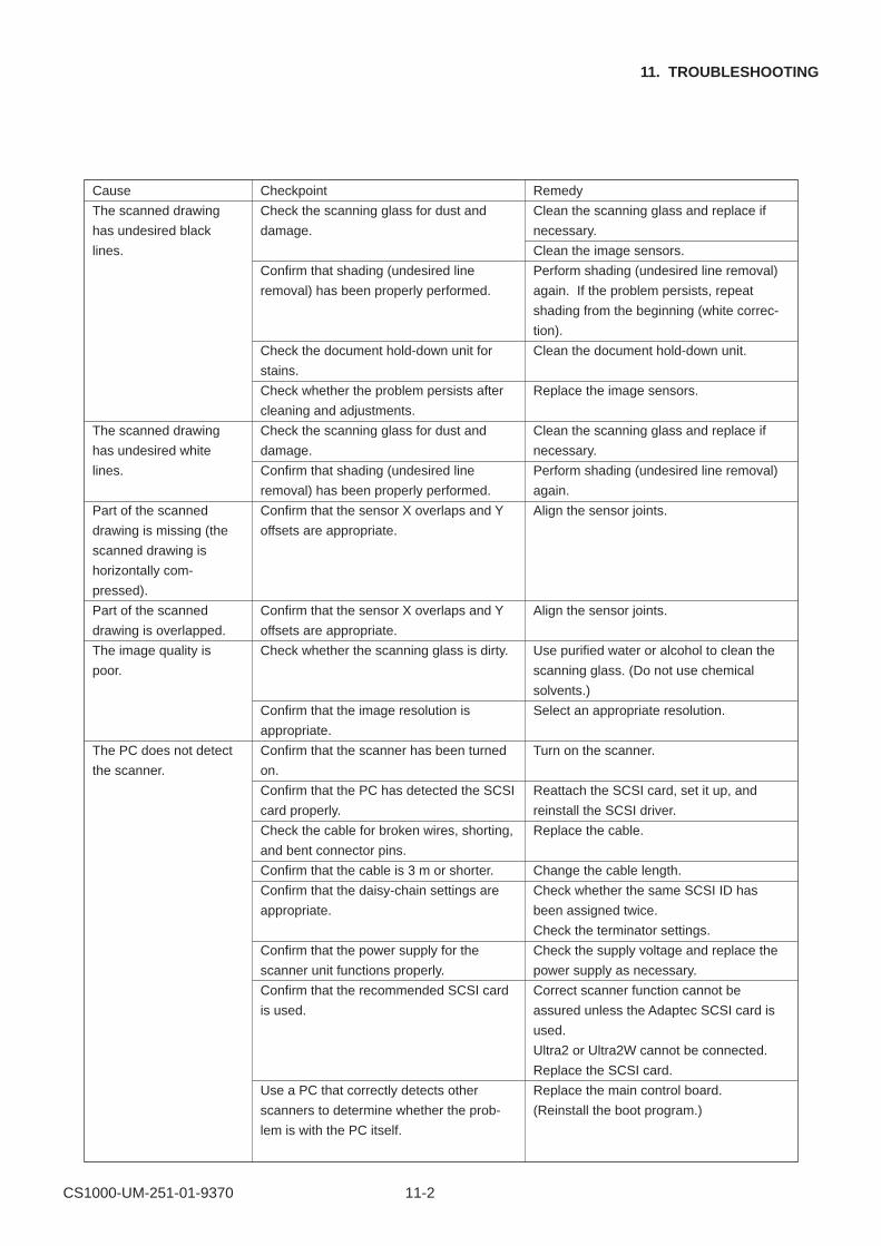
CS1000-UM-251-01-9370 11-2
11. TROUBLESHOOTING
Cause
The scanned drawing
has undesired black
lines.
The scanned drawing
has undesired white
lines.
Part of the scanned
drawing is missing (the
scanned drawing is
horizontally com-
pressed).
Part of the scanned
drawing is overlapped.
The image quality is
poor.
The PC does not detect
the scanner.
Remedy
Clean the scanning glass and replace if
necessary.
Clean the image sensors.
Perform shading (undesired line removal)
again. If the problem persists, repeat
shading from the beginning (white correc-
tion).
Clean the document hold-down unit.
Replace the image sensors.
Clean the scanning glass and replace if
necessary.
Perform shading (undesired line removal)
again.
Align the sensor joints.
Align the sensor joints.
Use purified water or alcohol to clean the
scanning glass. (Do not use chemical
solvents.)
Select an appropriate resolution.
Turn on the scanner.
Reattach the SCSI card, set it up, and
reinstall the SCSI driver.
Replace the cable.
Change the cable length.
Check whether the same SCSI ID has
been assigned twice.
Check the terminator settings.
Check the supply voltage and replace the
power supply as necessary.
Correct scanner function cannot be
assured unless the Adaptec SCSI card is
used.
Ultra2 or Ultra2W cannot be connected.
Replace the SCSI card.
Replace the main control board.
(Reinstall the boot program.)
Checkpoint
Check the scanning glass for dust and
damage.
Confirm that shading (undesired line
removal) has been properly performed.
Check the document hold-down unit for
stains.
Check whether the problem persists after
cleaning and adjustments.
Check the scanning glass for dust and
damage.
Confirm that shading (undesired line
removal) has been properly performed.
Confirm that the sensor X overlaps and Y
offsets are appropriate.
Confirm that the sensor X overlaps and Y
offsets are appropriate.
Check whether the scanning glass is dirty.
Confirm that the image resolution is
appropriate.
Confirm that the scanner has been turned
on.
Confirm that the PC has detected the SCSI
card properly.
Check the cable for broken wires, shorting,
and bent connector pins.
Confirm that the cable is 3 m or shorter.
Confirm that the daisy-chain settings are
appropriate.
Confirm that the power supply for the
scanner unit functions properly.
Confirm that the recommended SCSI card
is used.
Use a PC that correctly detects other
scanners to determine whether the prob-
lem is with the PC itself.
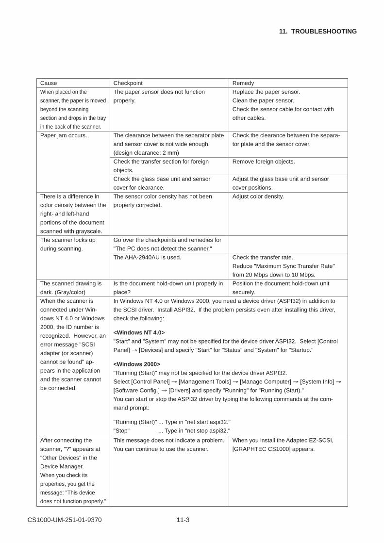
CS1000-UM-251-01-9370 11-3
11. TROUBLESHOOTING
Cause
When placed on the
scanner, the paper is moved
beyond the scanning
section and drops in the tray
in the back of the scanner.
Paper jam occurs.
There is a difference in
color density between the
right- and left-hand
portions of the document
scanned with grayscale.
The scanner locks up
during scanning.
The scanned drawing is
dark. (Gray/color)
When the scanner is
connected under Win-
dows NT 4.0 or Windows
2000, the ID number is
recognized. However, an
error message "SCSI
adapter (or scanner)
cannot be found" ap-
pears in the application
and the scanner cannot
be connected.
After connecting the
scanner, "?" appears at
"Other Devices" in the
Device Manager.
When you check its
properties, you get the
message: "This device
does not function properly."
Remedy
Replace the paper sensor.
Clean the paper sensor.
Check the sensor cable for contact with
other cables.
Check the clearance between the separa-
tor plate and the sensor cover.
Remove foreign objects.
Adjust the glass base unit and sensor
cover positions.
Adjust color density.
Check the transfer rate.
Reduce "Maximum Sync Transfer Rate"
from 20 Mbps down to 10 Mbps.
Position the document hold-down unit
securely.
When you install the Adaptec EZ-SCSI,
[GRAPHTEC CS1000] appears.
Checkpoint
The paper sensor does not function
properly.
The clearance between the separator plate
and sensor cover is not wide enough.
(design clearance: 2 mm)
Check the transfer section for foreign
objects.
Check the glass base unit and sensor
cover for clearance.
The sensor color density has not been
properly corrected.
Go over the checkpoints and remedies for
"The PC does not detect the scanner."
The AHA-2940AU is used.
Is the document hold-down unit properly in
place?
This message does not indicate a problem.
You can continue to use the scanner.
In Windows NT 4.0 or Windows 2000, you need a device driver (ASPI32) in addition to
the SCSI driver. Install ASPI32. If the problem persists even after installing this driver,
check the following:
<Windows NT 4.0>
"Start" and "System" may not be specified for the device driver ASPI32. Select [Control
Panel] → [Devices] and specify "Start" for "Status" and "System" for "Startup."
<Windows 2000>
"Running (Start)" may not be specified for the device driver ASPI32.
Select [Control Panel] → [Management Tools] → [Manage Computer] → [System Info] →
[Software Config.] → [Drivers] and specify "Running" for "Running (Start)."
You can start or stop the ASPI32 driver by typing the following commands at the com-
mand prompt:
"Running (Start)" ... Type in "net start aspi32."
"Stop" ... Type in "net stop aspi32."
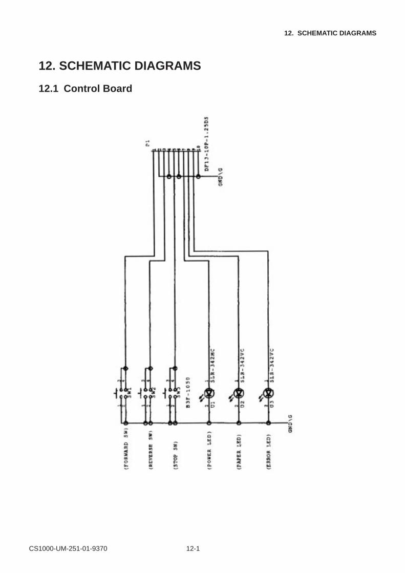
CS1000-UM-251-01-9370 12-1
12. SCHEMATIC DIAGRAMS
12. SCHEMATIC DIAGRAMS
12.1 Control Board
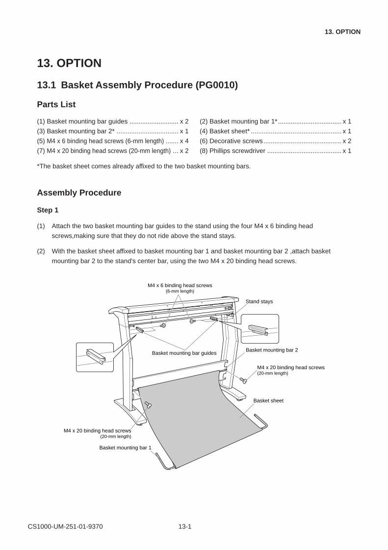
CS1000-UM-251-01-9370 13-1
13. OPTION
13. OPTION
13.1 Basket Assembly Procedure (PG0010)
Parts List
(1) Basket mounting bar guides ........................... x 2 (2) Basket mounting bar 1* ................................... x 1
(3) Basket mounting bar 2* .................................. x 1 (4) Basket sheet* .................................................. x 1
(5) M4 x 6 binding head screws (6-mm length) ....... x 4 (6) Decorative screws........................................... x 2
(7) M4 x 20 binding head screws (20-mm length) ... x 2 (8) Phillips screwdriver ......................................... x 1
*The basket sheet comes already affixed to the two basket mounting bars.
Assembly Procedure
Step 1
(1) Attach the two basket mounting bar guides to the stand using the four M4 x 6 binding head
screws,making sure that they do not ride above the stand stays.
(2) With the basket sheet affixed to basket mounting bar 1 and basket mounting bar 2 ,attach basket
mounting bar 2 to the stand's center bar, using the two M4 x 20 binding head screws.
Basket sheet
Basket mounting bar 1
Basket mounting bar 2
Stand stays
M4 x 20 binding head screws(20-mm length)
Basket mounting bar guides
M4 x 6 binding head screws(6-mm length)
M4 x 20 binding head screws(20-mm length)
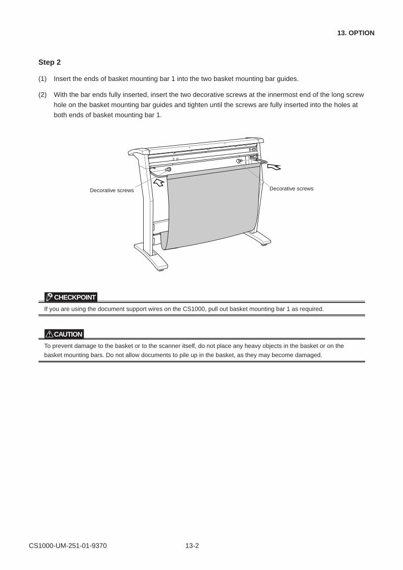
CS1000-UM-251-01-9370 13-2
13. OPTION
Step 2
(1) Insert the ends of basket mounting bar 1 into the two basket mounting bar guides.
(2) With the bar ends fully inserted, insert the two decorative screws at the innermost end of the long screw
hole on the basket mounting bar guides and tighten until the screws are fully inserted into the holes at
both ends of basket mounting bar 1.
Decorative screwsDecorative screws
CHECKPOINT
If you are using the document support wires on the CS1000, pull out basket mounting bar 1 as required.
CAUTION
To prevent damage to the basket or to the scanner itself, do not place any heavy objects in the basket or on the
basket mounting bars. Do not allow documents to pile up in the basket, as they may become damaged.
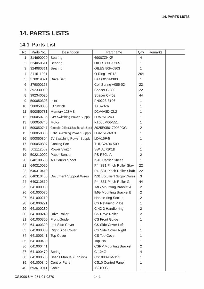
CS1000-UM-251-01-9370 14-1
14. PARTS LISTS
14. PARTS LISTS
14.1 Parts ListNo Parts No. Description Part name Q’ty Remarks
1 314690020 Bearing 6900ZZNXR 4
2 324050511 Bearing OILES 80F-0505 1
3 324080311 Bearing OILES 80F-0803 1
4 341511001 O Ring 1AP12 264
5 378019021 Drive Belt Belt 60S2M380 1
6 379000168 Coil Spring A085-02 22
7 392330090 Spacer C-309 22
8 392340090 Spacer C-409 44
9 500050303 Inlet FN9223-3106 1
10 500050305 ID Switch ID Switch 1
11 500050731 Memory 128MB D2V4A8D-CL2 1
12 500050736 24V Switching Power Supply LDA75F-24-H 1
13 500050745 Motor KT60LM06-551 1
14 500050747 Connection Cable (CIS Board to Main Board) 8925E050179030GG 2
15 500050803 3.3V Switching Power Supply LDA15F-3-3.3 1
16 500050804 5V Switching Power Supply LDA15F-5 1
17 500050807 Cooling Fan TUDC24B4-500 1
18 502112009 Power Switch SW, AJ7201B 1
19 502210002 Paper Sensor PS-R50L-A 2
20 640100533 A0 Carrier Sheet IS10 Carrier Sheet 1
21 640310090 P4 IS31 Pinch Roller Stay 22
22 640310410 P4 IS31 Pinch Roller Shaft 22
23 640310450 Document Support Wires IS31 Document Support Wires 3
24 640310510 P4 IS31 Pinch Roller G 44
25 641000060 IMG Mounting Bracket A 2
26 641000070 IMG Mounting Bracket B 2
27 641000210 Handle-ring Socket 2
28 641000221 CS Retaining Plate 1
29 641000230 C-42-2 Handle-ring 2
30 641000240 Drive Roller CS Drive Roller 2
31 641000300 Front Guide CS Front Guide 1
32 641000320 Left Side Cover CS Side Cover Left 1
33 641000330 Right Side Cover CS Side Cover Right 1
34 641000341 Top Cover CS Top Cover 1
35 641000430 Top Pin 1
36 641000441 CSRP Mounting Bracket 2
37 641000470 Spring C-124G 4
38 641000600 User's Manual (English) CS1000-UM-151 1
39 641000840 Control Panel CS10 Control Panel 1
40 693610011 Cable IS2100C-1 1
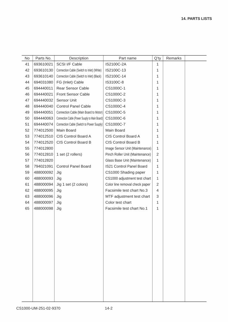
CS1000-UM-251-02-9370 14-2
14. PARTS LISTS
No Parts No. Description Part name Q’ty Remarks
41 693610021 SCSI I/F Cable IS2100C-2A 1
42 693610130 Connection Cable (Switch to Inlet) (White) IS2100C-13 1
43 693610140 Connection Cable (Switch to Inlet) (Black) IS2100C-14 1
44 694031080 FG (Inlet) Cable IS3100C-8 1
45 694440011 Rear Sensor Cable CS1000C-1 1
46 694440021 Front Sensor Cable CS1000C-2 1
47 694440032 Sensor Unit CS1000C-3 1
48 694440040 Control Panel Cable CS1000C-4 1
49 694440051 Connection Cable (Main Board to Motor) CS1000C-5 1
50 694440063 Connection Cable (Power Suuply to Main Board) CS1000C-6 1
51 694440074 Connection Cable (Switch to Power Suuply) CS1000C-7 1
52 774012500 Main Board Main Board 1
53 774012510 CIS Control Board A CIS Control Board A 1
54 774012520 CIS Control Board B CIS Control Board B 1
55 774012800 Image Sensor Unit (Maintenance) 1
56 774012810 1 set (2 rollers) Pinch Roller Unit (Maintenance) 2
57 774012820 Glass Base Unit (Maintenance) 1
58 794021091 Control Panel Board IS21 Control Panel Board 1
59 488000092 Jig CS1000 Shading paper 1
60 488000093 Jig CS1000 adjustment test chart 1
61 488000094 Jig 1 set (2 colors) Color line removal check paper 2
62 488000095 Jig Facsimile test chart No.3 4
63 488000096 Jig MTF adjustment test chart 3
64 488000097 Jig Color test chart 1
65 488000098 Jig Facsimile test chart No.1 1
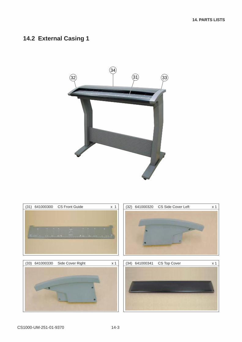
CS1000-UM-251-01-9370 14-3
14. PARTS LISTS
14.2 External Casing 1
32
34
3331
(32) 641000320 CS Side Cover Left x 1
(33) 641000330 Side Cover Right x 1 (34) 641000341 CS Top Cover x 1
(31) 641000300 CS Front Guide x 1
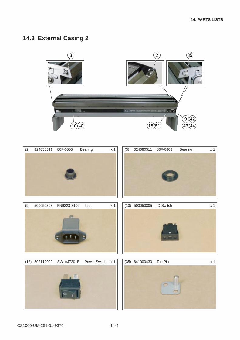
CS1000-UM-251-01-9370 14-4
14. PARTS LISTS
(9) 500050303 FN9223-3106 Inlet x 1
(3) 324080311 80F-0803 Bearing x 1(2) 324050511 80F-0505 Bearing x 1
(35) 641000430 Top Pin x 1
14.3 External Casing 2
(10) 500050305 ID Switch x 1
(18) 502112009 SW, AJ7201B Power Switch x 1
10 40
9 42
43 445118
3 2 35

CS1000-UM-251-01-9370 14-5
14. PARTS LISTS
(43) 693610140 IS2100C-14 Cable x 1 (44) 694031080 IS3100C-8 Cable x 1
(42) 693610130 IS2100C-13 Cable x 1(40) 693610011 IS2100C-1 Cable x 1
(51) 694440074 CS1000C-7 Cable x 1
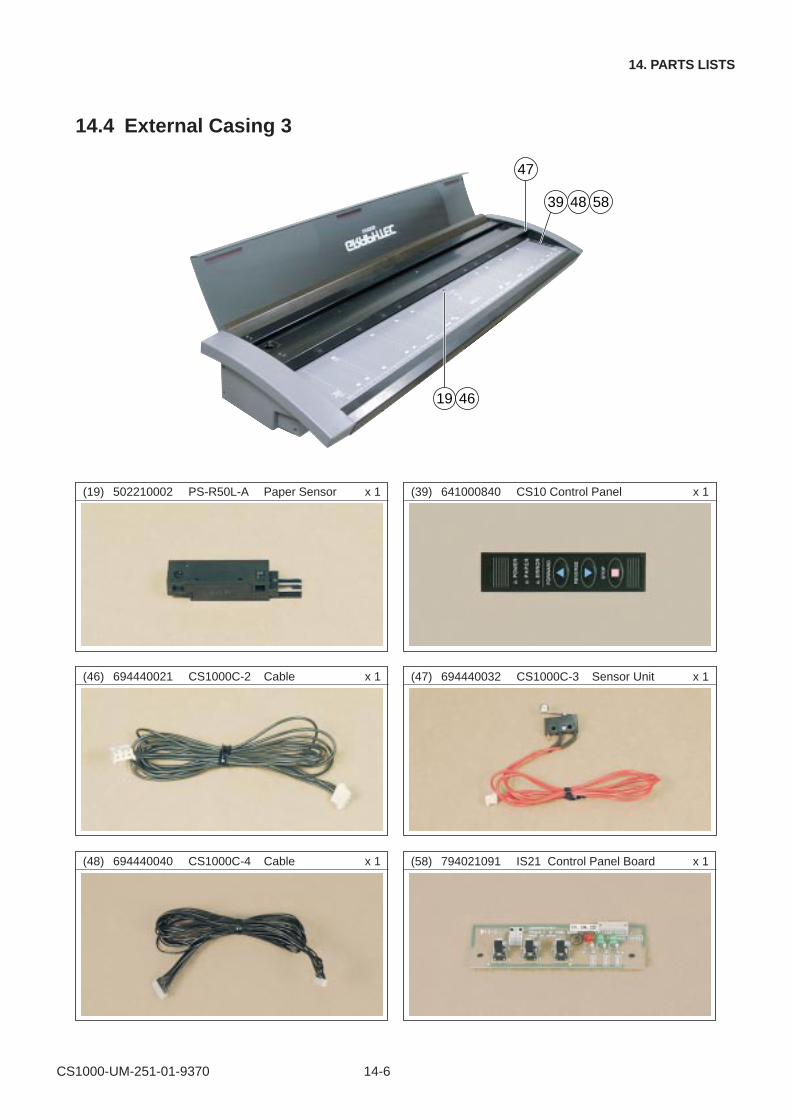
CS1000-UM-251-01-9370 14-6
14. PARTS LISTS
14.4 External Casing 3
(47) 694440032 CS1000C-3 Sensor Unit x 1(46) 694440021 CS1000C-2 Cable x 1
(58) 794021091 IS21 Control Panel Board x 1(48) 694440040 CS1000C-4 Cable x 1
(39) 641000840 CS10 Control Panel x 1
39 48 58
19 46
47
(19) 502210002 PS-R50L-A Paper Sensor x 1
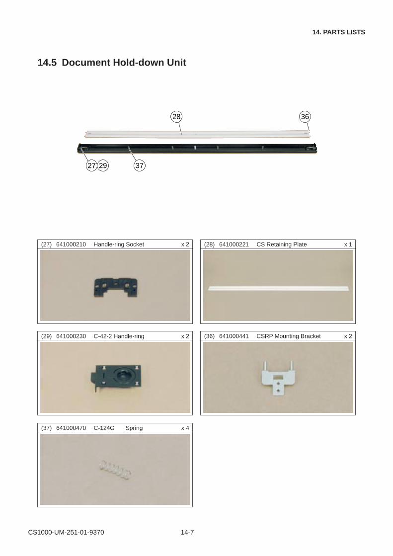
CS1000-UM-251-01-9370 14-7
14. PARTS LISTS
14.5 Document Hold-down Unit
(29) 641000230 C-42-2 Handle-ring x 2
(27) 641000210 Handle-ring Socket x 2
(37) 641000470 C-124G Spring x 4
(28) 641000221 CS Retaining Plate x 1
(36) 641000441 CSRP Mounting Bracket x 2
28 36
3727 29
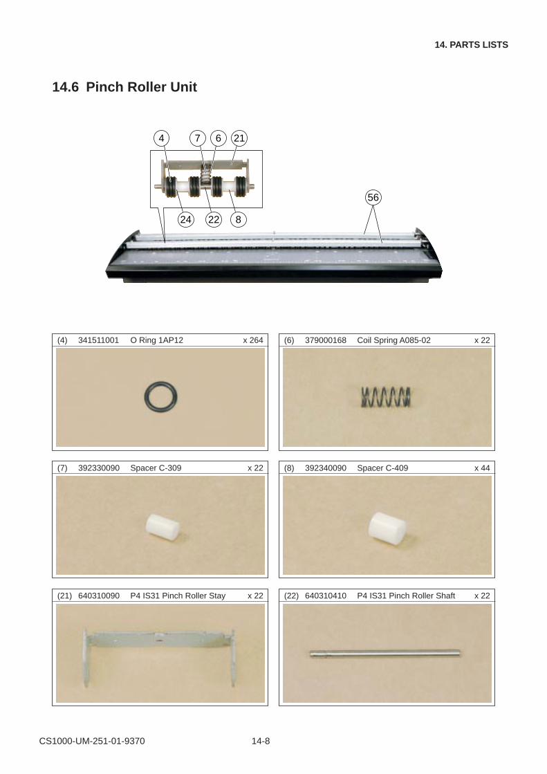
CS1000-UM-251-01-9370 14-8
14. PARTS LISTS
14.6 Pinch Roller Unit
(22) 640310410 P4 IS31 Pinch Roller Shaft x 22
(8) 392340090 Spacer C-409 x 44
(4) 341511001 O Ring 1AP12 x 264
(7) 392330090 Spacer C-309 x 22
56
6 21
82224
74
(6) 379000168 Coil Spring A085-02 x 22
(21) 640310090 P4 IS31 Pinch Roller Stay x 22
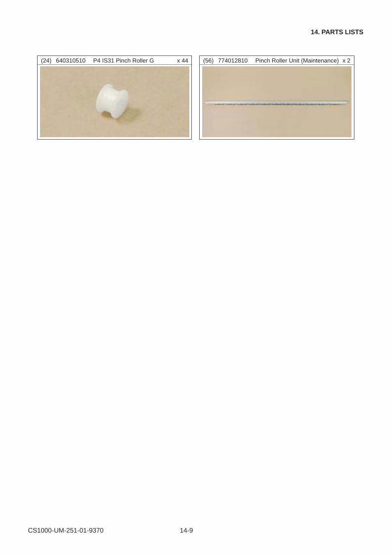
CS1000-UM-251-01-9370 14-9
14. PARTS LISTS
(24) 640310510 P4 IS31 Pinch Roller G x 44 (56) 774012810 Pinch Roller Unit (Maintenance) x 2
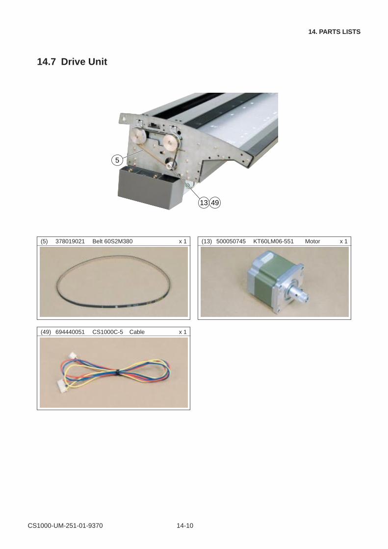
CS1000-UM-251-01-9370 14-10
14. PARTS LISTS
14.7 Drive Unit
(49) 694440051 CS1000C-5 Cable x 1
(5) 378019021 Belt 60S2M380 x 1 (13) 500050745 KT60LM06-551 Motor x 1
13 49
5
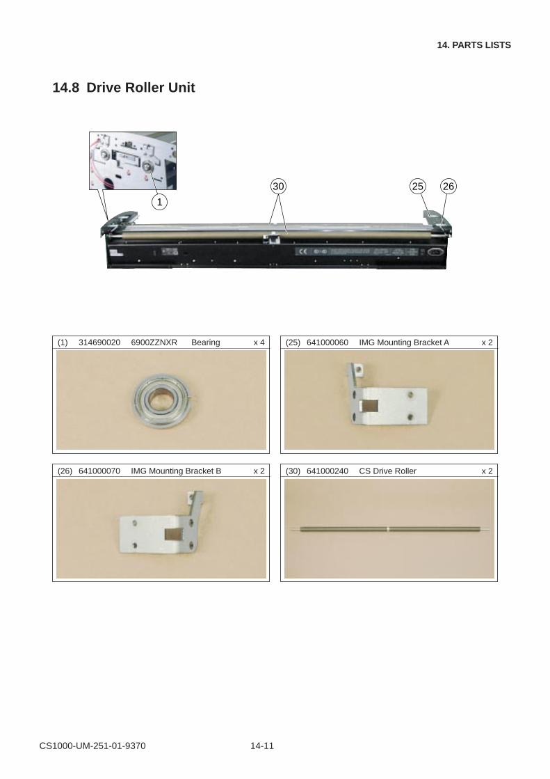
CS1000-UM-251-01-9370 14-11
14. PARTS LISTS
14.8 Drive Roller Unit
(25) 641000060 IMG Mounting Bracket A x 2
(30) 641000240 CS Drive Roller x 2
(1) 314690020 6900ZZNXR Bearing x 4
(26) 641000070 IMG Mounting Bracket B x 2
30 25 26
1
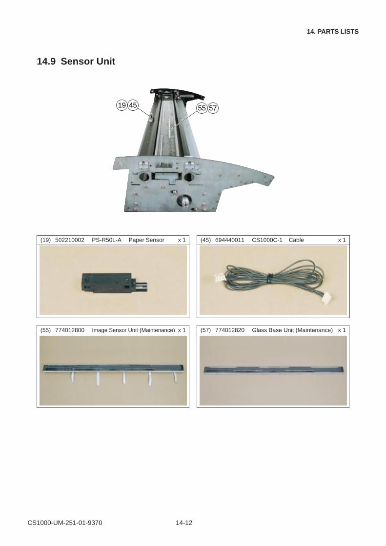
CS1000-UM-251-01-9370 14-12
14. PARTS LISTS
14.9 Sensor Unit
(19) 502210002 PS-R50L-A Paper Sensor x 1 (45) 694440011 CS1000C-1 Cable x 1
(55) 774012800 Image Sensor Unit (Maintenance) x 1 (57) 774012820 Glass Base Unit (Maintenance) x 1
55 574519
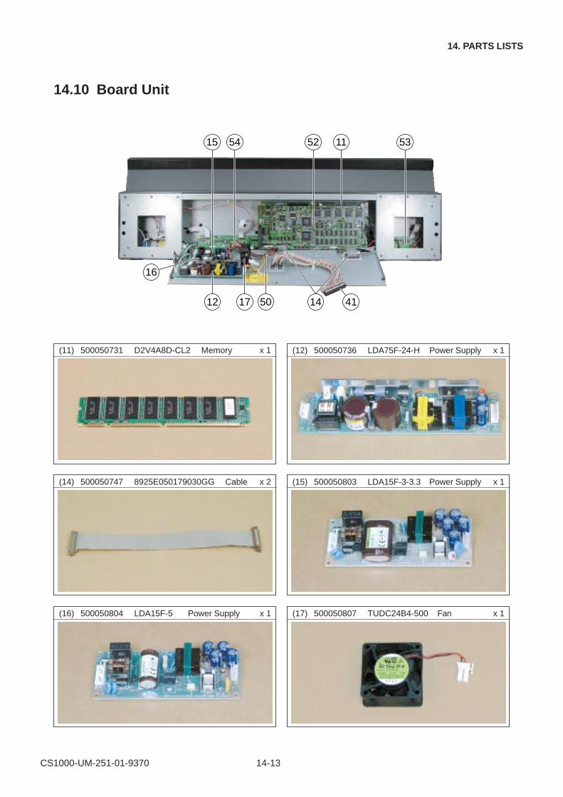
CS1000-UM-251-01-9370 14-13
14. PARTS LISTS
14.10 Board Unit
(11) 500050731 D2V4A8D-CL2 Memory x 1
12 41
16
17 50 14
15 54 52 11 53
(12) 500050736 LDA75F-24-H Power Supply x 1
(15) 500050803 LDA15F-3-3.3 Power Supply x 1
(16) 500050804 LDA15F-5 Power Supply x 1
(14) 500050747 8925E050179030GG Cable x 2
(17) 500050807 TUDC24B4-500 Fan x 1
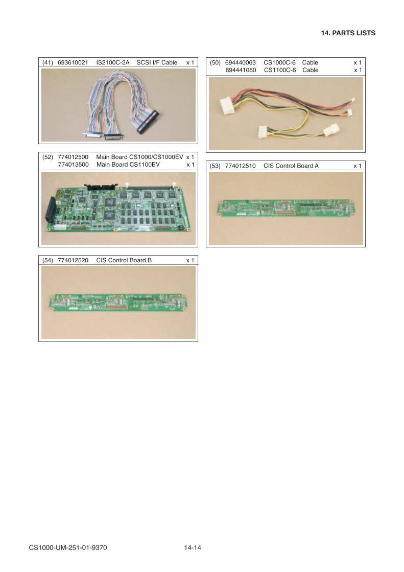
CS1000-UM-251-01-9370 14-14
14. PARTS LISTS
(50) 694440063 CS1000C-6 Cable x 1(41) 693610021 IS2100C-2A SCSI I/F Cable x 1
(53) 774012510 CIS Control Board A x 1
(54) 774012520 CIS Control Board B x 1
(52) 774012500 Main Board CS1000/CS1000EV x 1774013500 Main Board CS1100EV x 1
694441060 CS1100C-6 Cable x 1
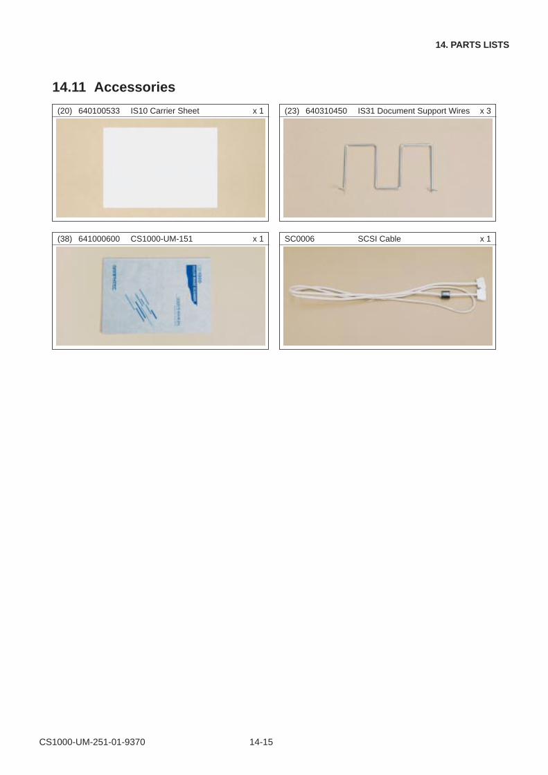
CS1000-UM-251-01-9370 14-15
14. PARTS LISTS
14.11 Accessories
(23) 640310450 IS31 Document Support Wires x 3
(38) 641000600 CS1000-UM-151 x 1
(20) 640100533 IS10 Carrier Sheet x 1
SC0006 SCSI Cable x 1
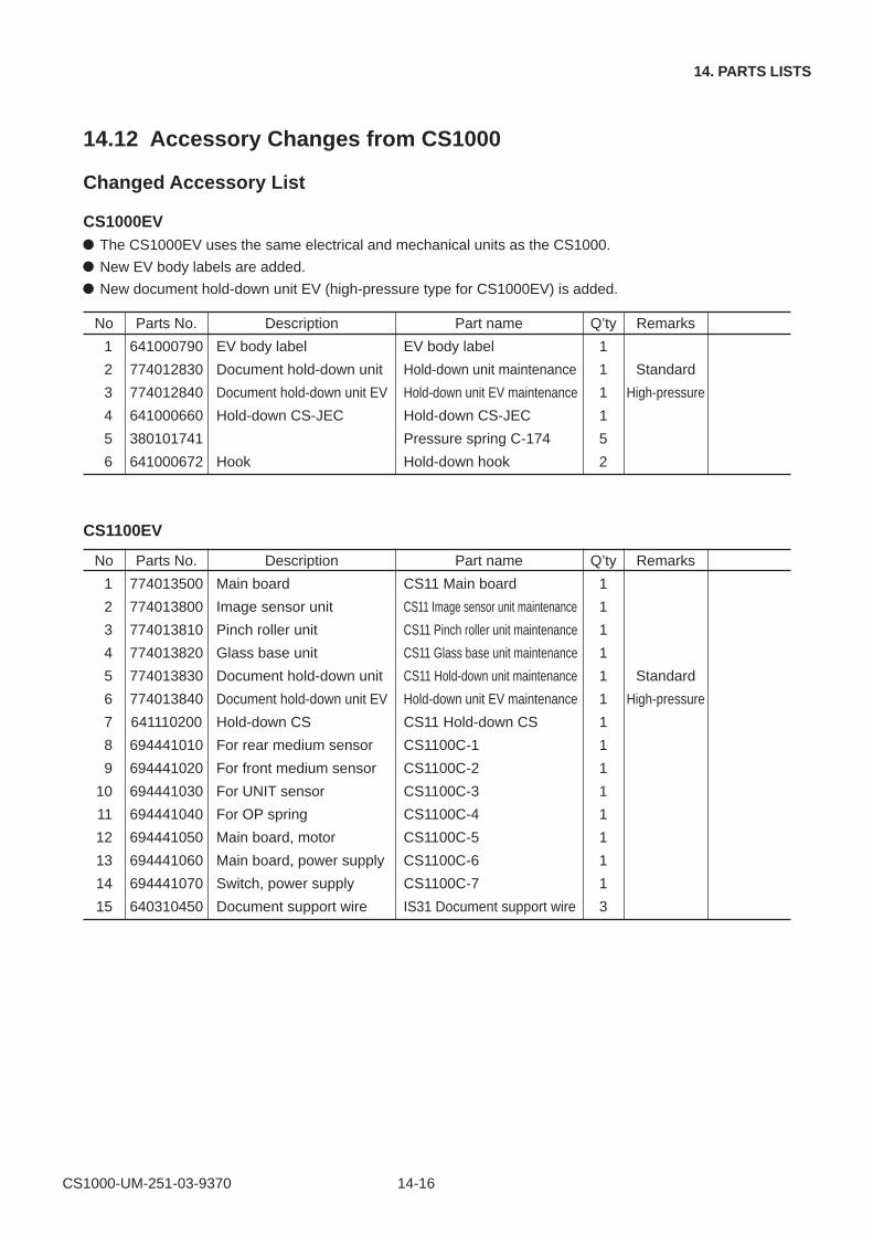
CS1000-UM-251-03-9370 14-16
14. PARTS LISTS
14.12 Accessory Changes from CS1000
Changed Accessory List
CS1000EVThe CS1000EV uses the same electrical and mechanical units as the CS1000.
New EV body labels are added.
New document hold-down unit EV (high-pressure type for CS1000EV) is added.
CS1100EV
No Parts No. Description Part name Q’ty Remarks
1 641000790 EV body label EV body label 1
2 774012830 Document hold-down unit Hold-down unit maintenance 1 Standard
3 774012840 Document hold-down unit EV Hold-down unit EV maintenance 1 High-pressure
4 641000660 Hold-down CS-JEC Hold-down CS-JEC 1
5 380101741 Pressure spring C-174 5
6 641000672 Hook Hold-down hook 2
No Parts No. Description Part name Q’ty Remarks
1 774013500 Main board CS11 Main board 1
2 774013800 Image sensor unit CS11 Image sensor unit maintenance 1
3 774013810 Pinch roller unit CS11 Pinch roller unit maintenance 1
4 774013820 Glass base unit CS11 Glass base unit maintenance 1
5 774013830 Document hold-down unit CS11 Hold-down unit maintenance 1 Standard
6 774013840 Document hold-down unit EV Hold-down unit EV maintenance 1 High-pressure
7 641110200 Hold-down CS CS11 Hold-down CS 1
8 694441010 For rear medium sensor CS1100C-1 1
9 694441020 For front medium sensor CS1100C-2 1
10 694441030 For UNIT sensor CS1100C-3 1
11 694441040 For OP spring CS1100C-4 1
12 694441050 Main board, motor CS1100C-5 1
13 694441060 Main board, power supply CS1100C-6 1
14 694441070 Switch, power supply CS1100C-7 1
15 640310450 Document support wire IS31 Document support wire 3
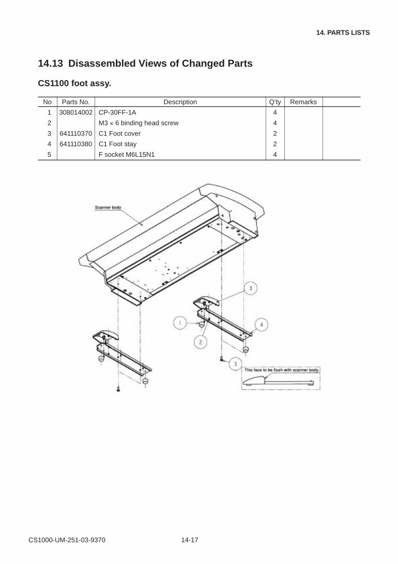
CS1000-UM-251-03-9370 14-17
14. PARTS LISTS
14.13 Disassembled Views of Changed Parts
CS1100 foot assy.
No Parts No. Description Q’ty Remarks
1 308014002 CP-30FF-1A 4
2 M3 × 6 binding head screw 4
3 641110370 C1 Foot cover 2
4 641110380 C1 Foot stay 2
5 F socket M6L15N1 4
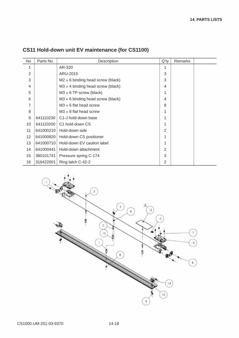
CS1000-UM-251-03-9370 14-18
14. PARTS LISTS
CS11 Hold-down unit EV maintenance (for CS1100)
No Parts No. Description Q’ty Remarks
1 AR-320 1
2 ARU-2015 3
3 M2 × 6 binding head screw (black) 3
4 M3 × 4 binding head screw (black) 4
5 M3 × 6 TP screw (black) 1
6 M3 × 6 binding head screw (black) 4
7 M3 × 6 flat head screw 8
8 M3 × 8 flat head screw 1
9 641110230 C1-J hold-down base 1
10 641110200 C1 hold-down CS 1
11 641000210 Hold-down side 2
12 641000820 Hold-down CS positioner 1
13 641000710 Hold-down EV caution label 1
14 641000441 Hold-down attachment 2
15 380101741 Pressure spring C-174 3
16 316422001 Ring latch C-42-2 2
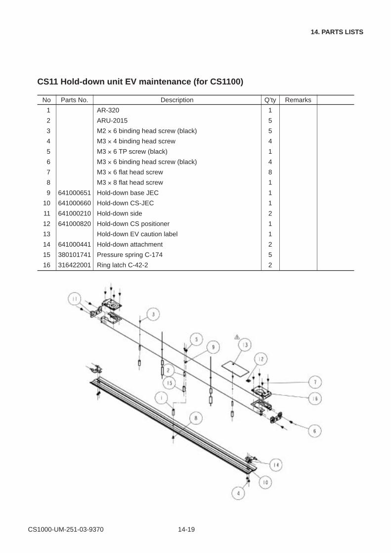
CS1000-UM-251-03-9370 14-19
14. PARTS LISTS
CS11 Hold-down unit EV maintenance (for CS1100)
No Parts No. Description Q’ty Remarks
1 AR-320 1
2 ARU-2015 5
3 M2 × 6 binding head screw (black) 5
4 M3 × 4 binding head screw 4
5 M3 × 6 TP screw (black) 1
6 M3 × 6 binding head screw (black) 4
7 M3 × 6 flat head screw 8
8 M3 × 8 flat head screw 1
9 641000651 Hold-down base JEC 1
10 641000660 Hold-down CS-JEC 1
11 641000210 Hold-down side 2
12 641000820 Hold-down CS positioner 1
13 Hold-down EV caution label 1
14 641000441 Hold-down attachment 2
15 380101741 Pressure spring C-174 5
16 316422001 Ring latch C-42-2 2