Embed Size (px)
Citation preview

CS1000EV/1100EV
USER’S MANUALMANUAL NO. CS1000-UM-153
COLOR IMAGE SCANNER
– i –
TO ENSURE SAFE AND CORRECT USE
• To ensure safe and correct use of your Image Scanner, read this Manual thoroughly beforeuse.
• After having read this Manual, keep it in a handy location for quick reference as needed.• Do not permit small children to touch the Image Scanner.• The following describes important points for safe operation. Please be sure to observe
them strictly.
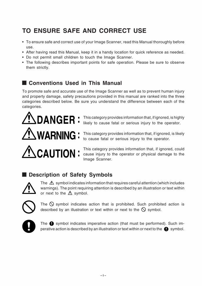
Conventions Used in This ManualTo promote safe and accurate use of the Image Scanner as well as to prevent human injuryand property damage, safety precautions provided in this manual are ranked into the threecategories described below. Be sure you understand the difference between each of thecategories.
This category provides information that, if ignored, is highlylikely to cause fatal or serious injury to the operator.
This category provides information that, if ignored, is likelyto cause fatal or serious injury to the operator.
This category provides information that, if ignored, couldcause injury to the operator or physical damage to theImage Scanner.
Description of Safety SymbolsThe symbol indicates information that requires careful attention (which includeswarnings). The point requiring attention is described by an illustration or text withinor next to the symbol.
The symbol indicates action that is prohibited. Such prohibited action isdescribed by an illustration or text within or next to the symbol.
The symbol indicates imperative action (that must be performed). Such im-perative action is described by an illustration or text within or next to the symbol.
CAUTION :
DANGER :
WARNING :
– ii –
Safety Precautions
WARNING
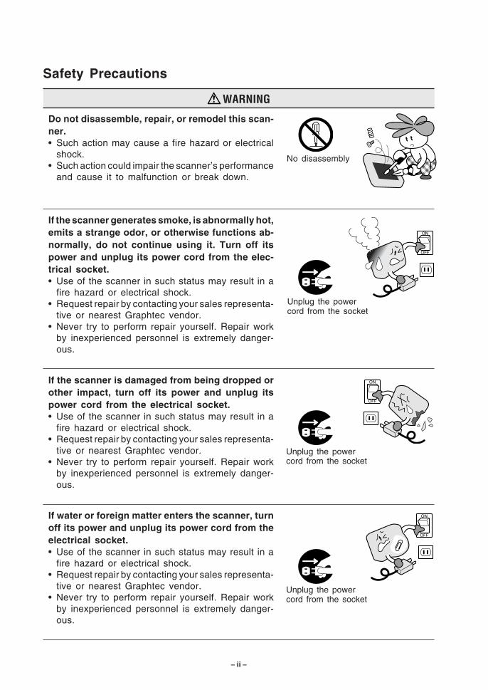
Do not disassemble, repair, or remodel this scan-ner.• Such action may cause a fire hazard or electrical
shock.• Such action could impair the scanner’s performance
and cause it to malfunction or break down.
If the scanner generates smoke, is abnormally hot,emits a strange odor, or otherwise functions ab-normally, do not continue using it. Turn off itspower and unplug its power cord from the elec-trical socket.• Use of the scanner in such status may result in a
fire hazard or electrical shock.• Request repair by contacting your sales representa-
tive or nearest Graphtec vendor.• Never try to perform repair yourself. Repair work
by inexperienced personnel is extremely danger-ous.
If the scanner is damaged from being dropped orother impact, turn off its power and unplug itspower cord from the electrical socket.• Use of the scanner in such status may result in a
fire hazard or electrical shock.• Request repair by contacting your sales representa-
tive or nearest Graphtec vendor.• Never try to perform repair yourself. Repair work
by inexperienced personnel is extremely danger-ous.
If water or foreign matter enters the scanner, turnoff its power and unplug its power cord from theelectrical socket.• Use of the scanner in such status may result in a
fire hazard or electrical shock.• Request repair by contacting your sales representa-
tive or nearest Graphtec vendor.• Never try to perform repair yourself. Repair work
by inexperienced personnel is extremely danger-ous.
No disassembly
Unplug the powercord from the socket
Unplug the powercord from the socket
Unplug the powercord from the socket
– iii –
Safety Precautions (Continued)
WARNING
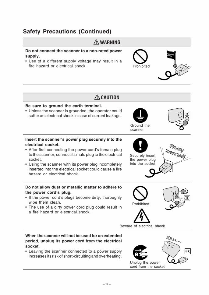
Do not connect the scanner to a non-rated powersupply.• Use of a different supply voltage may result in a
fire hazard or electrical shock.
CAUTION
Be sure to ground the earth terminal.• Unless the scanner is grounded, the operator could
suffer an electrical shock in case of current leakage.
Insert the scanner’s power plug securely into theelectrical socket.• After first connecting the power cord’s female plug
to the scanner, connect its male plug to the electricalsocket.
• Using the scanner with its power plug incompletelyinserted into the electrical socket could cause a firehazard or electrical shock.
Do not allow dust or metallic matter to adhere tothe power cord’s plug.• If the power cord’s plugs become dirty, thoroughly
wipe them clean.• The use of a dirty power cord plug could result in
a fire hazard or electrical shock.
When the scanner will not be used for an extendedperiod, unplug its power cord from the electricalsocket.• Leaving the scanner connected to a power supply
increases its risk of short-circuiting and overheating.
Ground thescanner
Prohibited
Beware of electrical shock
Prohibited
Unplug the powercord from the socket
Securely insertthe power pluginto the socket
– iv –
Safety Precautions (Continued)
CAUTION
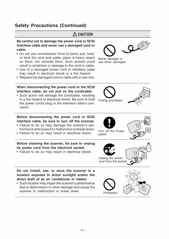
Be careful not to damage the power cord or SCSIinterface cable and never use a damaged cord orcable.• Do not use unnecessary force to bend, pull, twist,
or bind the cord and cable, place a heavy objecton them, nor remodel them. Such actions couldresult in scratches or damage to the cord or cable.
• Use of a damaged power cord or interface cablemay result in electrical shock or a fire hazard.
• Replace the damaged cord or cable with a new one.
When disconnecting the power cord or the SCSIinterface cable, do not pull on the cord/cable.• Such action will damage the cord/cable, resulting
in a fire hazard or electrical shock. Be sure to holdthe power cord’s plug or the interface cable’s con-nector.
Before disconnecting the power cord or SCSIinterface cable, be sure to turn off the scanner.• Failure to do so may damage the scanner’s per-
formance and cause it to malfunction or break down.• Failure to do so may result in electrical shock.
Before cleaning the scanner, be sure to unplugits power cord from the electrical socket.• Failure to do so may result in electrical shock.
Do not install, use, or store the scanner in alocation exposed to direct sunlight and/or thedirect draft of an air conditioner or heater.• Such location may impair the scanner’s performance
due to deformation or other damage and cause thescanner to malfunction or break down.
Never damage oruse when damaged
Turn off the Powerswitch
Pulling prohibited
Unplug the powercord from the socket
Prohibited
– v –
Safety Precautions (Continued)
CAUTION
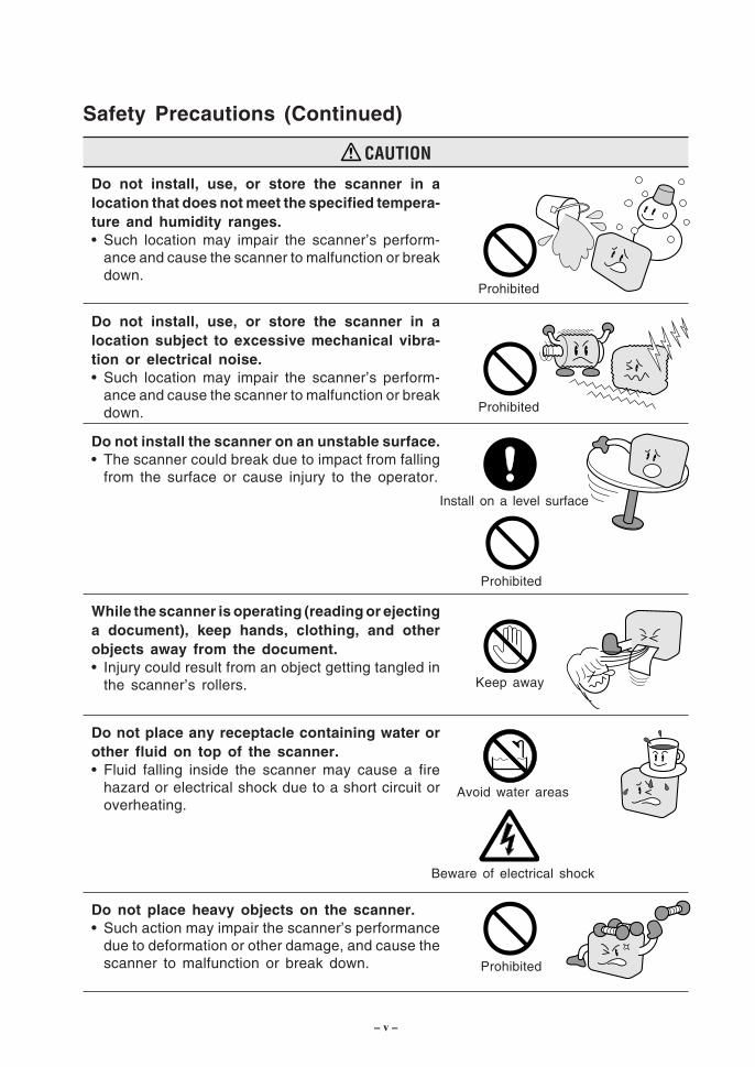
Do not install, use, or store the scanner in alocation that does not meet the specified tempera-ture and humidity ranges.• Such location may impair the scanner’s perform-
ance and cause the scanner to malfunction or breakdown.
Do not install, use, or store the scanner in alocation subject to excessive mechanical vibra-tion or electrical noise.• Such location may impair the scanner’s perform-
ance and cause the scanner to malfunction or breakdown.
Do not install the scanner on an unstable surface.• The scanner could break due to impact from falling
from the surface or cause injury to the operator.
While the scanner is operating (reading or ejectinga document), keep hands, clothing, and otherobjects away from the document.• Injury could result from an object getting tangled in
the scanner’s rollers.
Do not place any receptacle containing water orother fluid on top of the scanner.• Fluid falling inside the scanner may cause a fire
hazard or electrical shock due to a short circuit oroverheating.
Do not place heavy objects on the scanner.• Such action may impair the scanner’s performance
due to deformation or other damage, and cause thescanner to malfunction or break down.
Prohibited
Avoid water areas
Beware of electrical shock
Prohibited
Keep away
Prohibited
Install on a level surface
Prohibited
– vi –
Safety Precautions (Continued)
CAUTION
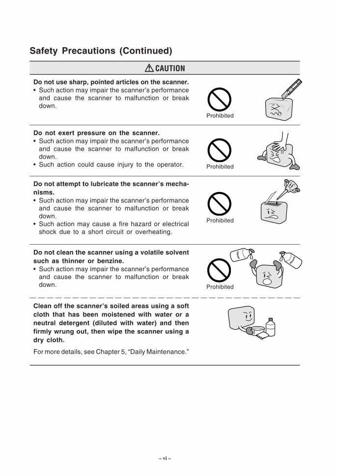
Do not use sharp, pointed articles on the scanner.• Such action may impair the scanner’s performance
and cause the scanner to malfunction or breakdown.
Do not exert pressure on the scanner.• Such action may impair the scanner’s performance
and cause the scanner to malfunction or breakdown.
• Such action could cause injury to the operator.
Do not attempt to lubricate the scanner’s mecha-nisms.• Such action may impair the scanner’s performance
and cause the scanner to malfunction or breakdown.
• Such action may cause a fire hazard or electricalshock due to a short circuit or overheating.
Do not clean the scanner using a volatile solventsuch as thinner or benzine.• Such action may impair the scanner’s performance
and cause the scanner to malfunction or breakdown.
Clean off the scanner’s soiled areas using a softcloth that has been moistened with water or aneutral detergent (diluted with water) and thenfirmly wrung out, then wipe the scanner using adry cloth.
For more details, see Chapter 5, “Daily Maintenance.”
Prohibited
Prohibited
Prohibited
Prohibited
– vii –
INTRODUCTION
Thank you for purchasing the CS1000EV/CS1100EV Image Scanner. The CS1000EV/CS1100EV is capable of accurately performing high-speed scanning of documents rangingin size from ISO A4 to ANSI E (CS1000EV) or ANSI D (CS1100EV).An image scanner scans an image by illuminating a document and then reading the reflectedlight using linear image sensors. The CS1000EV/CS1100EV converts the scanned imagedata to 8-bit color, 256-tone grayscale or bilevel (monochrome) data, which is then transmittedrapidly to the host system via the SCSI interface.This User’s Manual describes how to operate the CS1000EV/CS1100EV, and also includesusage precautions. Read the manual thoroughly prior to use in order to ensure fullunderstanding of the product’s features, and to ensure effective use. Keep the manualin a safe place where it can be accessed easily whenever necessary.
Items in this manual marked are precautions to ensure safe use.Please be sure to observe them strictly.
Notes Regarding This Manual
• All rights reserved. No part of this publication may be reproduced, stored in a retrievalsystem, or transmitted, in any form or by any means, without the prior written permissionof Graphtec Corporation.
• The specifications and other information in this manual are subject to change withoutnotice.
• While every effort has been made to provide complete and accurate information, pleasecontact your sales representative or nearest Graphtec vendor if you find any unclearor mistaken information or have other comments or suggestions.
• Notwithstanding the stipulation in the preceding paragraph, Graphtec Corporation as-sumes no liability for damages resulting from either the use of the information containedherein or from use of the product.
• All names of companies, brands, logotypes, and products appearing in this manual arethe trademarks or registered trademarks of their respective companies.
Trademarks
Windows is a U.S. registered trademark of Microsoft Corp. Other product names mentionedherein are trademarks or registered trademarks of their respective owners.
– viii –
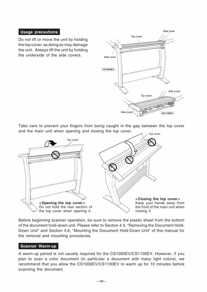
Usage precautions
Do not lift or move the unit by holdingthe top cover, as doing so may damagethe unit. Always lift the unit by holdingthe underside of the side covers.
Top cover
Top cover
Side cover
Side cover
Side cover
Side cover CS1100EV
CS1000EV
Take care to prevent your fingers from being caught in the gap between the top coverand the main unit when opening and closing the top cover.
Top cover
Top cover
Before beginning scanner operation, be sure to remove the plastic sheet from the bottomof the document hold-down unit. Please refer to Section 4.5, “Removing the Document Hold-Down Unit” and Section 4.6, “Mounting the Document Hold-Down Unit” of this manual forthe removal and mounting procedures.
Scanner Warm-up
A warm-up period is not usually required for the CS1000EV/CS1100EV. However, if youplan to scan a color document (in particular a document with many light colors), werecommend that you allow the CS1000EV/CS1100EV to warm up for 10 minutes beforescanning the document.
<Opening the top cover>Do not hold the rear section ofthe top cover when opening it.
<Closing the top cover>Keep your hands away fromthe front of the main unit whenclosing it.
– ix –
Contents
TO ENSURE SAFE AND CORRECT USE .................................................... iConventions Used in This Manual ........................................................................... iDescription of Safety Symbols ................................................................................. iSafety Precautions .................................................................................................... iiIntroduction ................................................................................................................. vii
1. OVERVIEW ........................................................................................................... 1-11.1 Features .......................................................................................................... 1-11.2 Unpacking the Scanner ................................................................................. 1-2
2. PREPARATION ................................................................................................... 2-12.1 Assembling the Scanner (CS1000EV) ......................................................... 2-12.2 Part Names and Functions............................................................................ 2-32.3 Attaching the Document Support Wires ....................................................... 2-62.4 Storing the EV Document Hold-Down Unit .................................................. 2-8
3. PREPARING TO OPERATE THE SCANNER ....................................... 3-13.1 System Requirements .................................................................................... 3-13.2 Connecting the Scanner to a Power Supply ............................................... 3-23.3 Connecting the SCSI Cable .......................................................................... 3-33.4 Setting the ID Number ................................................................................... 3-53.5 Turning the Scanner On or Off .................................................................... 3-63.6 Connecting the Scanner to a Computer ...................................................... 3-73.7 Checking the Interface Connection .............................................................. 3-163.8 Installing the Scanning Master 21+ Application .......................................... 3-183.9 Installing the Scanning Master Copy Color Application ............................. 3-19
4. LOADING A DOCUMENT .............................................................................. 4-14.1 Compatible Document Types ........................................................................ 4-14.2 Loading a Document ...................................................................................... 4-34.3 Using the Carrier Sheet ................................................................................. 4-54.4 Using the EV Document Hold-Down Unit .................................................... 4-64.5 Removing the Document Hold-Down Unit ................................................... 4-74.6 Mounting the Document Hold-Down Unit ..................................................... 4-9
5. DAILY MAINTENANCE ................................................................................... 5-15.1 Cleaning the Image Sensors ......................................................................... 5-15.2 Cleaning the Paper Sensors ......................................................................... 5-35.3 Cleaning the Document Hold-Down Unit ..................................................... 5-45.4 Removing a Jammed Document ................................................................... 5-55.5 Calibration ....................................................................................................... 5-7
– x –
6. TROUBLESHOOTING PROCEDURES ..................................................... 6-16.1 The Scanner Is Turned On But Doesn’t Operate at All ............................. 6-16.2 The Scanner Operates Improperly After Connection to the Computer ..... 6-16.3 The Control Panel’s Red ERROR Lamp Is Lit ........................................... 6-26.4 The Control Panel’s Red ERROR Lamp Is Flashing ................................. 6-36.5 The Document Isn’t Properly Fed to the Initial Scanning Position ........... 6-36.6 After Scanning, Image Data Becomes Black or White .............................. 6-36.7 The Image Quality Has Dropped .................................................................. 6-36.8 The Input Image Data Is Incorrectly Aligned .............................................. 6-46.9 Smudges Not Appearing in the Original Document Appear
in the Scanned Data ...................................................................................... 6-66.10 The Image-Data Color Intensity Differs ........................................................ 6-66.11 The Document Length Differs from the Scanned Data Length ................. 6-66.12 Stripes or Moire Patterns Which Are Not in the Original Document
Appear in the Scanned Data ........................................................................ 6-6
APPENDIX A. OPTIONAL AND MISCELLANEOUS ITEMS ................ A-1
APPENDIX B. STANDARD SPECIFICATIONS .......................................... B-1
APPENDIX C. EXTERNAL VIEW ..................................................................... C-1
INDEX ............................................................................................................................ Idex-1
CS1000EV/1100EV 1 – 1
1. OVERVIEW
1. OVERVIEW
1.1 Features
600-dpi optical resolution for high-precision image scanning
Scanning with an optical resolution of 600 dpi allows even complex and difficult-to-scandocuments, such as CAD drawings, electronic files, and mapping data to be scannedrapidly and with high precision. Scanning Master 21+ (scanner software included asa standard accessory) can be used to adjust the resolution in five levels (200 dpi to800 dpi) to suit the scanned document.
Compatible document widths range from 210 mm to 1000 mm (CS1000EV), or to630 mm (CS1100EV)
Compatible with document sizes from ISO A4 up to ANSI E (CS1000EV) or ANSI D(CS1100EV)
Capable of color and grayscale scanning
Capable of scanning in color (8-bit color) or grayscale (256 shades)
Capable of reading long-axis data
Long-axis images are supported with a maximum length of approximately four meterseach.
Compact and lightweight design
A compact design was achieved by using a document travel system that employs closely-adhered image sensors in the sensor unit (five rows arranged in a zigzag pattern).
Image-processing functions
Use of the scanning software provided lets you set image-processing functions for thescanning of a document.
Interface
The interface conforms to the SCSI-2 standard.
1 – 2 CS1000EV/1100EV
1. OVERVIEW
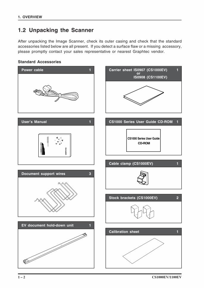
1.2 Unpacking the Scanner
After unpacking the Image Scanner, check its outer casing and check that the standardaccessories listed below are all present. If you detect a surface flaw or a missing accessory,please promptly contact your sales representative or nearest Graphtec vendor.
Standard Accessories
Power cable 1 Carrier sheet IS0907 (CS1000EV) 1 orIS0908 (CS1100EV)
CS1000 Series User Guide CD-ROM 1
CS1000 Series User Guide CD-ROM
User’s Manual 1
CS
1000E
V/1
110E
V US
ER
’S M
AN
UA
LM
AN
UA
L N
O. C
S10
00-U
M-1
52
CO
LO
R IM
AG
E S
CA
NN
ER
Document support wires 3
Cable clamp (CS1000EV) 1
Stock brackets (CS1000EV) 2
EV document hold-down unit 1
Calibration sheet 1
CS1000EV/1100EV 2 – 1
2. PREPARATION
2. PREPARATION
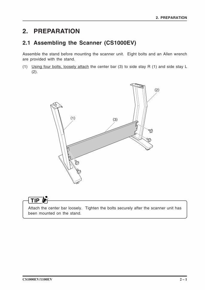
2.1 Assembling the Scanner (CS1000EV)
Assemble the stand before mounting the scanner unit. Eight bolts and an Allen wrenchare provided with the stand.
(1) Using four bolts, loosely attach the center bar (3) to side stay R (1) and side stay L(2).
(1)
(2)
(3)
Attach the center bar loosely. Tighten the bolts securely after the scanner unit hasbeen mounted on the stand.
2 – 2 CS1000EV/1100EV
2. PREPARATION
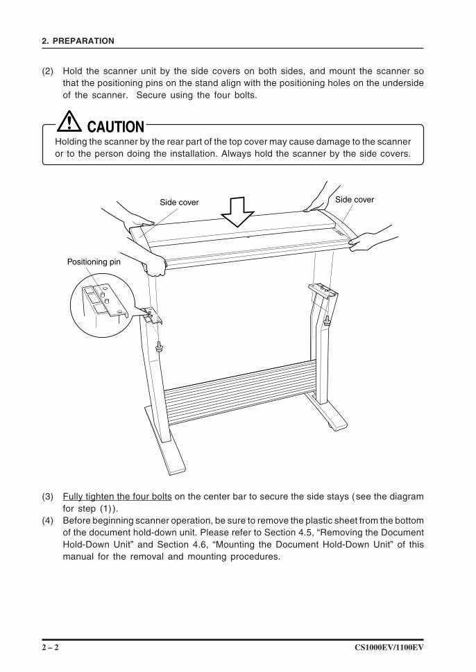
(2) Hold the scanner unit by the side covers on both sides, and mount the scanner sothat the positioning pins on the stand align with the positioning holes on the undersideof the scanner. Secure using the four bolts.
Holding the scanner by the rear part of the top cover may cause damage to the scanneror to the person doing the installation. Always hold the scanner by the side covers.
Side cover
Positioning pin
Side cover
(3) Fully tighten the four bolts on the center bar to secure the side stays (see the diagramfor step (1) ).
(4) Before beginning scanner operation, be sure to remove the plastic sheet from the bottomof the document hold-down unit. Please refer to Section 4.5, “Removing the DocumentHold-Down Unit” and Section 4.6, “Mounting the Document Hold-Down Unit” of thismanual for the removal and mounting procedures.
CS1000EV/1100EV 2 – 3
2. PREPARATION
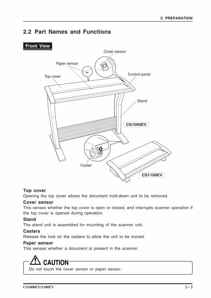
2.2 Part Names and Functions
Front View
CS1100EV
CS1000EV
Cover sensor
Paper sensor
Top cover
Caster
Control panel
Stand
Top coverOpening the top cover allows the document hold-down unit to be removed.
Cover sensorThis senses whether the top cover is open or closed, and interrupts scanner operation ifthe top cover is opened during operation.
StandThe stand unit is assembled for mounting of the scanner unit.
CastersRelease the lock on the casters to allow the unit to be moved.
Paper sensorThis senses whether a document is present in the scanner.
Do not touch the cover sensor or paper sensor.
2 – 4 CS1000EV/1100EV
2. PREPARATION
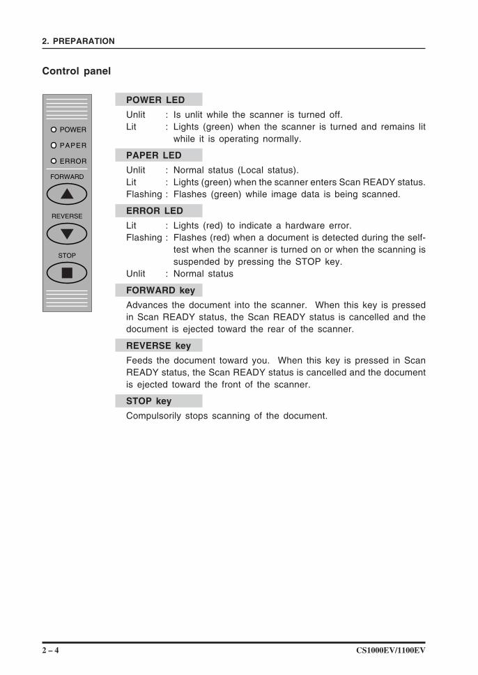
Control panel
POWER LED
Unlit : Is unlit while the scanner is turned off.Lit : Lights (green) when the scanner is turned and remains lit
while it is operating normally.
PAPER LED
Unlit : Normal status (Local status).Lit : Lights (green) when the scanner enters Scan READY status.Flashing : Flashes (green) while image data is being scanned.
ERROR LED
Lit : Lights (red) to indicate a hardware error.Flashing : Flashes (red) when a document is detected during the self-
test when the scanner is turned on or when the scanning issuspended by pressing the STOP key.
Unlit : Normal status
FORWARD key
Advances the document into the scanner. When this key is pressedin Scan READY status, the Scan READY status is cancelled and thedocument is ejected toward the rear of the scanner.
REVERSE key
Feeds the document toward you. When this key is pressed in ScanREADY status, the Scan READY status is cancelled and the documentis ejected toward the front of the scanner.
STOP key
Compulsorily stops scanning of the document.
CS1000EV/1100EV 2 – 5
2. PREPARATION
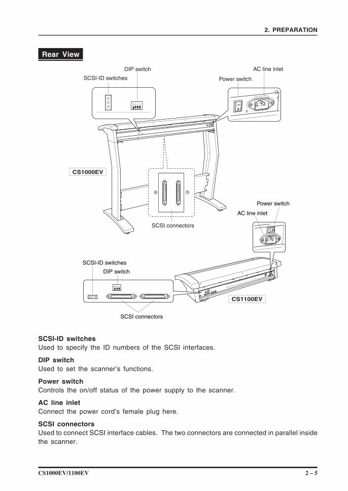
Rear View
4 3 2 1
4 3 2 12
SCSI-ID switches
DIP switch
AC line inlet
Power switch
SCSI connectors
CS1100EV
CS1000EV
SCSI-ID switches
DIP switch
Power switch
AC line inlet
SCSI connectors
SCSI-ID switchesUsed to specify the ID numbers of the SCSI interfaces.
DIP switchUsed to set the scanner’s functions.
Power switchControls the on/off status of the power supply to the scanner.
AC line inletConnect the power cord’s female plug here.
SCSI connectorsUsed to connect SCSI interface cables. The two connectors are connected in parallel insidethe scanner.
2 – 6 CS1000EV/1100EV
2. PREPARATION
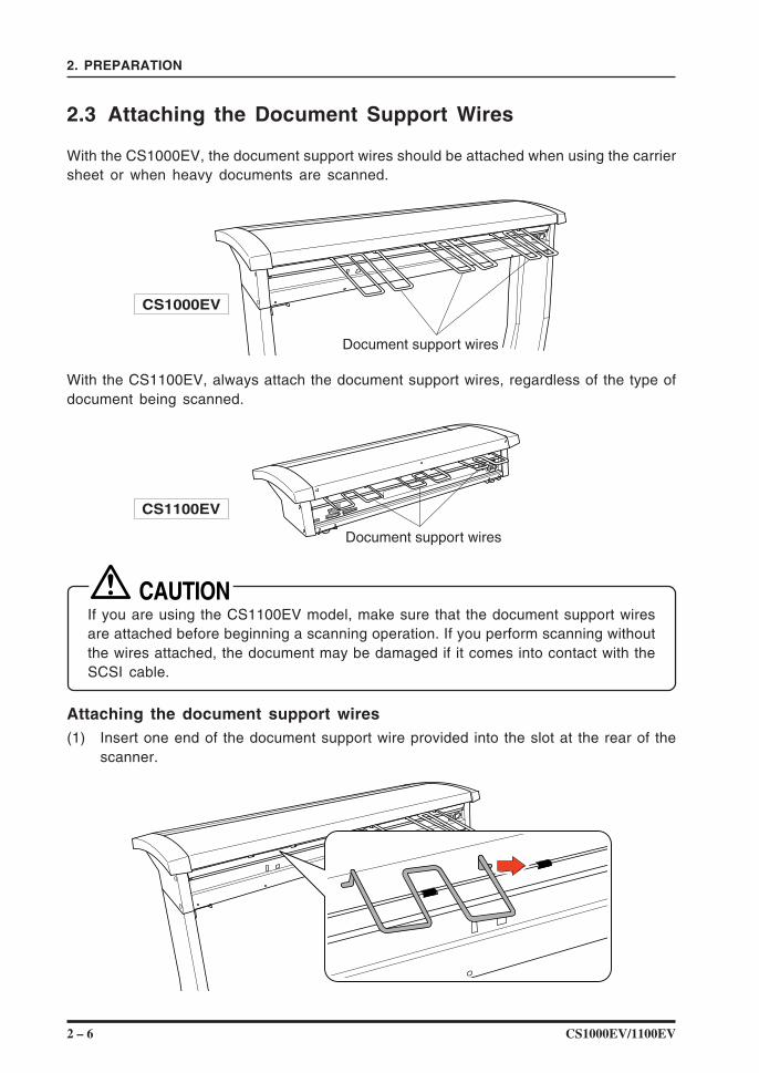
2.3 Attaching the Document Support Wires
With the CS1000EV, the document support wires should be attached when using the carriersheet or when heavy documents are scanned.
Document support wires
CS1000EV
With the CS1100EV, always attach the document support wires, regardless of the type ofdocument being scanned.
CS1100EV
Document support wires
If you are using the CS1100EV model, make sure that the document support wiresare attached before beginning a scanning operation. If you perform scanning withoutthe wires attached, the document may be damaged if it comes into contact with theSCSI cable.
Attaching the document support wires(1) Insert one end of the document support wire provided into the slot at the rear of the
scanner.
CS1000EV/1100EV 2 – 7
2. PREPARATION
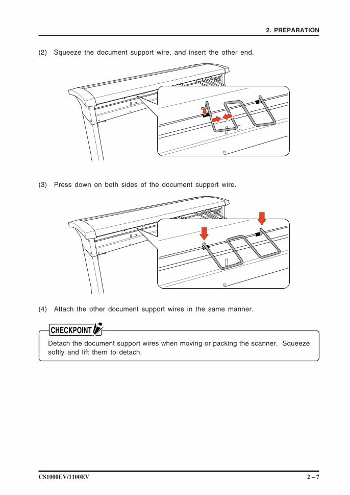
(2) Squeeze the document support wire, and insert the other end.
(3) Press down on both sides of the document support wire.
(4) Attach the other document support wires in the same manner.
Detach the document support wires when moving or packing the scanner. Squeezesoftly and lift them to detach.
2 – 8 CS1000EV/1100EV
2. PREPARATION
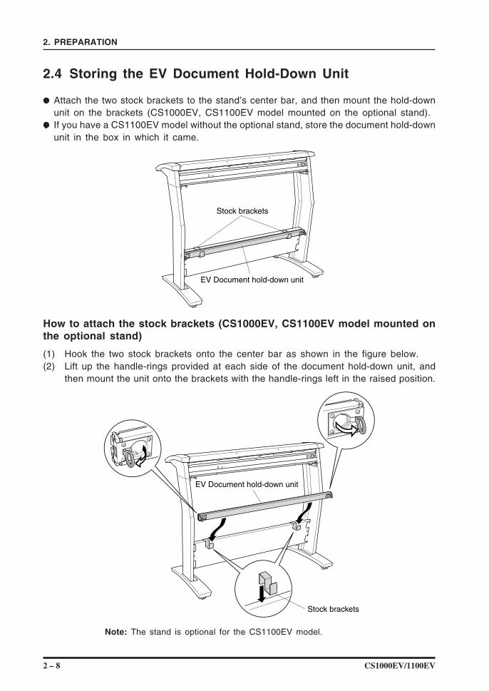
2.4 Storing the EV Document Hold-Down Unit
Attach the two stock brackets to the stand’s center bar, and then mount the hold-downunit on the brackets (CS1000EV, CS1100EV model mounted on the optional stand).If you have a CS1100EV model without the optional stand, store the document hold-downunit in the box in which it came.
Stock brackets
EV Document hold-down unit
How to attach the stock brackets (CS1000EV, CS1100EV model mounted onthe optional stand)
(1) Hook the two stock brackets onto the center bar as shown in the figure below.(2) Lift up the handle-rings provided at each side of the document hold-down unit, and
then mount the unit onto the brackets with the handle-rings left in the raised position.
Stock brackets
EV Document hold-down unit
Note: The stand is optional for the CS1100EV model.
CS1000EV/1100EV 3 – 1
3. PREPARING TO OPERATE THE SCANNER
3. PREPARING TO OPERATE THE SCANNER
3.1 System Requirements
The minimum system requirements for running the scanner’s hardware and software arelisted below.
Operating system: Windows 95/98/Me, Windows NT 4.0, Windows 2000/XP or laterCPU: Pentium 133 MHz or higherMemory: 32 MB or moreMonitor: 1024 × 768 pixels, 256 colors or moreEnough disk space to store dataMouseSCSI board by Adaptec
Recommended environment
For binary monochrome dataCPU: Pentium 200 MHz or higherMemory: 64 MB or moreSCSI board by Adaptec (PCI type)
For grayscale dataCPU: Pentium III 550 MHz or higherMemory: 256 MB or moreMonitor: 1024 × 768 pixels, High Color or higher resolutionSCSI board by Adaptec (PCI type)
For 8-bit color dataCPU: Pentium III 866 MHz or higherMemory: 512 MB or moreMonitor: 1024 × 768 pixels, True Color or higherSCSI board by Adaptec (PCI type)
The system configuration should correspond to the recommended specifications listedhere, in order to ensure the optimum capabilities of the scanner.Use with a system configuration below the recommended specifications will affect thescanning speed and prevent the scanner from operating to its specified capabilities.To edit an A1-size or larger grayscale document with a resolution of 400 dpi or higher,or an 8-bit color document, you may need more than the recommended memory sizesabove. Depending on the type of document, you may not be able to scan in the documenteven if you increase the memory size.
3 – 2 CS1000EV/1100EV
3. PREPARING TO OPERATE THE SCANNER
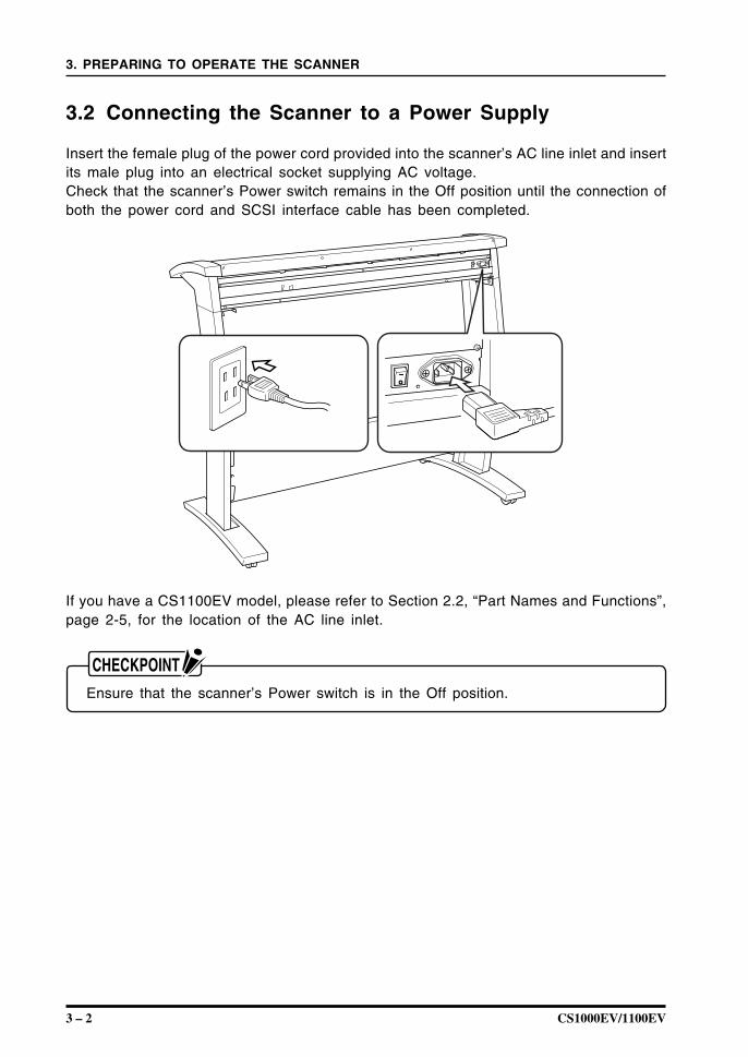
3.2 Connecting the Scanner to a Power Supply
Insert the female plug of the power cord provided into the scanner’s AC line inlet and insertits male plug into an electrical socket supplying AC voltage.Check that the scanner’s Power switch remains in the Off position until the connection ofboth the power cord and SCSI interface cable has been completed.
If you have a CS1100EV model, please refer to Section 2.2, “Part Names and Functions”,page 2-5, for the location of the AC line inlet.
Ensure that the scanner’s Power switch is in the Off position.
CS1000EV/1100EV 3 – 3
3. PREPARING TO OPERATE THE SCANNER
3.3 Connecting the SCSI Cable
Obtain a SCSI interface cable (optional) that is compatible with the computer to be connected.
Compatible CablesThe cable must have half-pitch pin-type 50-pin connectors.To connect multiple SCSI devices in a daisy-chain* arrangement, the total cable lengthmust be no longer than three meters.Among Graphtec cables, the SC0006 or SC0006 2M model can be used (dependingon the shape of the connector on the computer’s SCSI interface board).
* Daisy-chain: A method for connecting peripheral devices in a ring arrangement
The use of an incompatible cable may cause the scanner to malfunction or damagethe interface.If the cable comes into contact with the document, use the cable clamp provided asa standard accessory to fasten the cable to the underside of the scanner.
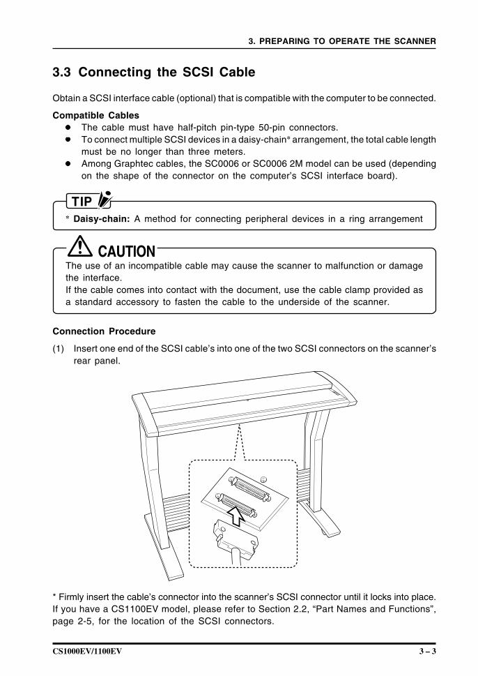
Connection Procedure
(1) Insert one end of the SCSI cable’s into one of the two SCSI connectors on the scanner’srear panel.
* Firmly insert the cable’s connector into the scanner’s SCSI connector until it locks into place.If you have a CS1100EV model, please refer to Section 2.2, “Part Names and Functions”,page 2-5, for the location of the SCSI connectors.
3 – 4 CS1000EV/1100EV
3. PREPARING TO OPERATE THE SCANNER
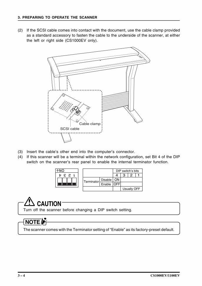
(2) If the SCSI cable comes into contact with the document, use the cable clamp providedas a standard accessory to fasten the cable to the underside of the scanner, at eitherthe left or right side (CS1000EV only).
SCSI cableCable clamp
(3) Insert the cable’s other end into the computer’s connector.(4) If this scanner will be a terminal within the network configuration, set Bit 4 of the DIP
switch on the scanner’s rear panel to enable the internal terminator function.
1 2 3 4
4 3 2 1
ON
DIP switch’s bits
ONOFF
Usually OFF
TerminatorDisableEnable
Turn off the scanner before changing a DIP switch setting.
The scanner comes with the Terminator setting of “Enable” as its factory-preset default.
CS1000EV/1100EV 3 – 5
3. PREPARING TO OPERATE THE SCANNER
3.4 Setting the ID Number
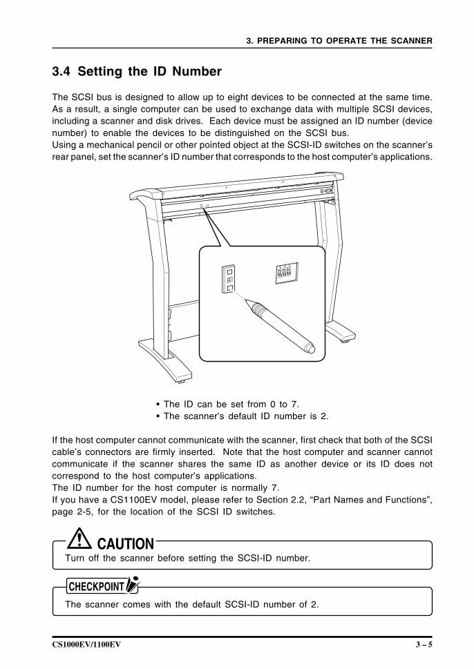
The SCSI bus is designed to allow up to eight devices to be connected at the same time.As a result, a single computer can be used to exchange data with multiple SCSI devices,including a scanner and disk drives. Each device must be assigned an ID number (devicenumber) to enable the devices to be distinguished on the SCSI bus.Using a mechanical pencil or other pointed object at the SCSI-ID switches on the scanner’srear panel, set the scanner’s ID number that corresponds to the host computer’s applications.
2
3 2 1• The ID can be set from 0 to 7.• The scanner’s default ID number is 2.
If the host computer cannot communicate with the scanner, first check that both of the SCSIcable’s connectors are firmly inserted. Note that the host computer and scanner cannotcommunicate if the scanner shares the same ID as another device or its ID does notcorrespond to the host computer’s applications.The ID number for the host computer is normally 7.If you have a CS1100EV model, please refer to Section 2.2, “Part Names and Functions”,page 2-5, for the location of the SCSI ID switches.
Turn off the scanner before setting the SCSI-ID number.
The scanner comes with the default SCSI-ID number of 2.
3 – 6 CS1000EV/1100EV
3. PREPARING TO OPERATE THE SCANNER
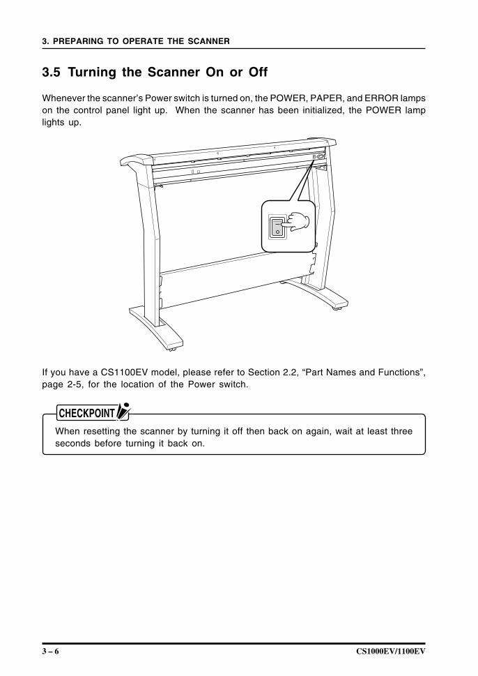
3.5 Turning the Scanner On or Off
Whenever the scanner’s Power switch is turned on, the POWER, PAPER, and ERROR lampson the control panel light up. When the scanner has been initialized, the POWER lamplights up.
If you have a CS1100EV model, please refer to Section 2.2, “Part Names and Functions”,page 2-5, for the location of the Power switch.
When resetting the scanner by turning it off then back on again, wait at least threeseconds before turning it back on.
CS1000EV/1100EV 3 – 7
3. PREPARING TO OPERATE THE SCANNER
3.6 Connecting the Scanner to a Computer
Before you can start connecting the scanner to the computer, you need to prepare (confirm)the computer system’s environment.
(1) Confirm that the computer’s operating system has been properly installed.(2) Confirm that a SCSI adapter has been connected to the computer.(3) Confirm that the SCSI driver has been installed in the computer.
Connecting the CS1000EV/CS1100EV to a Computer for the First Time
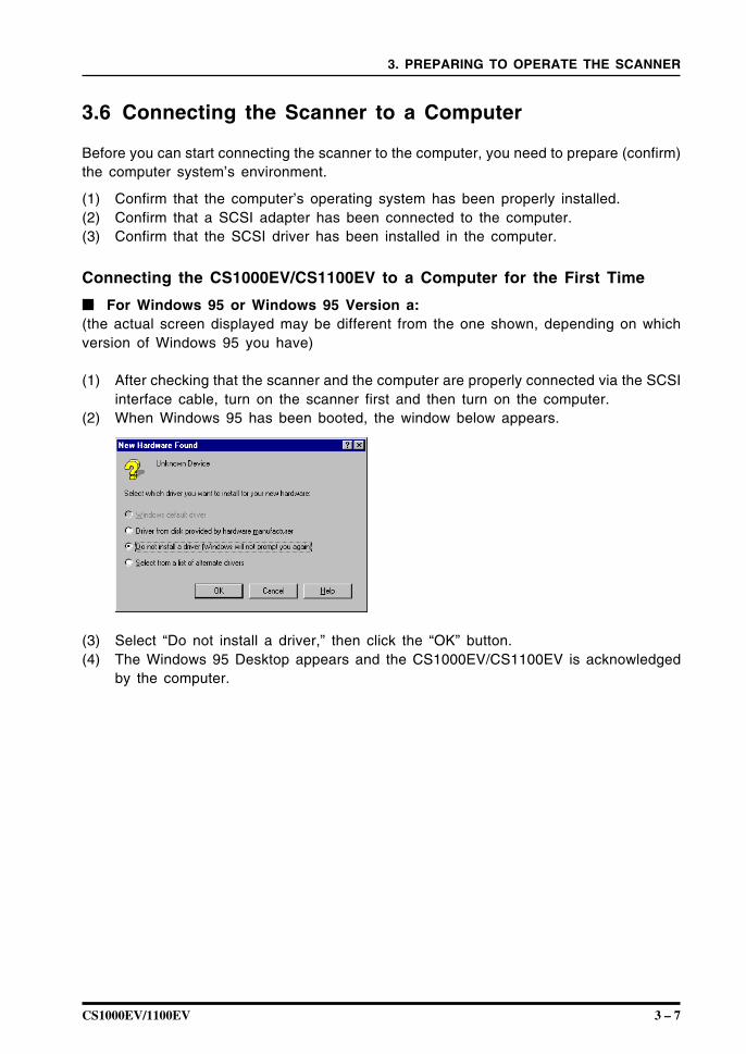
For Windows 95 or Windows 95 Version a:(the actual screen displayed may be different from the one shown, depending on whichversion of Windows 95 you have)
(1) After checking that the scanner and the computer are properly connected via the SCSIinterface cable, turn on the scanner first and then turn on the computer.
(2) When Windows 95 has been booted, the window below appears.
(3) Select “Do not install a driver,” then click the “OK” button.(4) The Windows 95 Desktop appears and the CS1000EV/CS1100EV is acknowledged
by the computer.
3 – 8 CS1000EV/1100EV
3. PREPARING TO OPERATE THE SCANNER
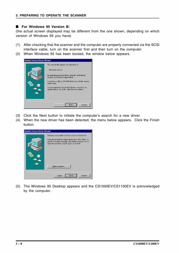
For Windows 95 Version B:(the actual screen displayed may be different from the one shown, depending on whichversion of Windows 95 you have)
(1) After checking that the scanner and the computer are properly connected via the SCSIinterface cable, turn on the scanner first and then turn on the computer.
(2) When Windows 95 has been booted, the window below appears.
(3) Click the Next button to initiate the computer’s search for a new driver.(4) When the new driver has been detected, the menu below appears. Click the Finish
button.
(5) The Windows 95 Desktop appears and the CS1000EV/CS1100EV is acknowledgedby the computer.
CS1000EV/1100EV 3 – 9
3. PREPARING TO OPERATE THE SCANNER
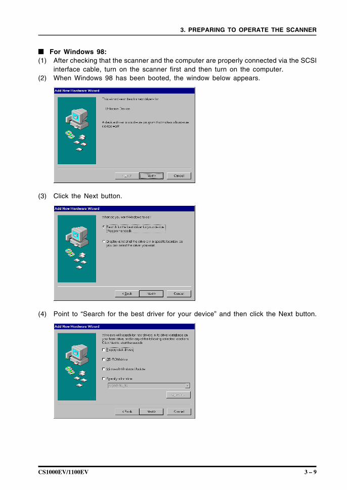
For Windows 98:(1) After checking that the scanner and the computer are properly connected via the SCSI
interface cable, turn on the scanner first and then turn on the computer.(2) When Windows 98 has been booted, the window below appears.
(3) Click the Next button.
(4) Point to “Search for the best driver for your device” and then click the Next button.
3 – 10 CS1000EV/1100EV
3. PREPARING TO OPERATE THE SCANNER
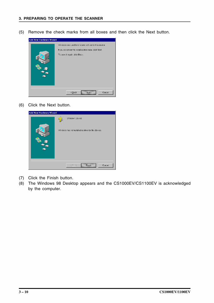
(5) Remove the check marks from all boxes and then click the Next button.
(6) Click the Next button.
(7) Click the Finish button.(8) The Windows 98 Desktop appears and the CS1000EV/CS1100EV is acknowledged
by the computer.
CS1000EV/1100EV 3 – 11
3. PREPARING TO OPERATE THE SCANNER
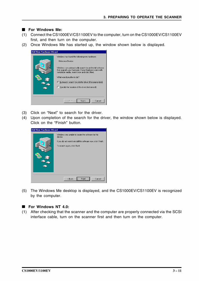
For Windows Me:(1) Connect the CS1000EV/CS1100EV to the computer, turn on the CS1000EV/CS1100EV
first, and then turn on the computer.(2) Once Windows Me has started up, the window shown below is displayed.
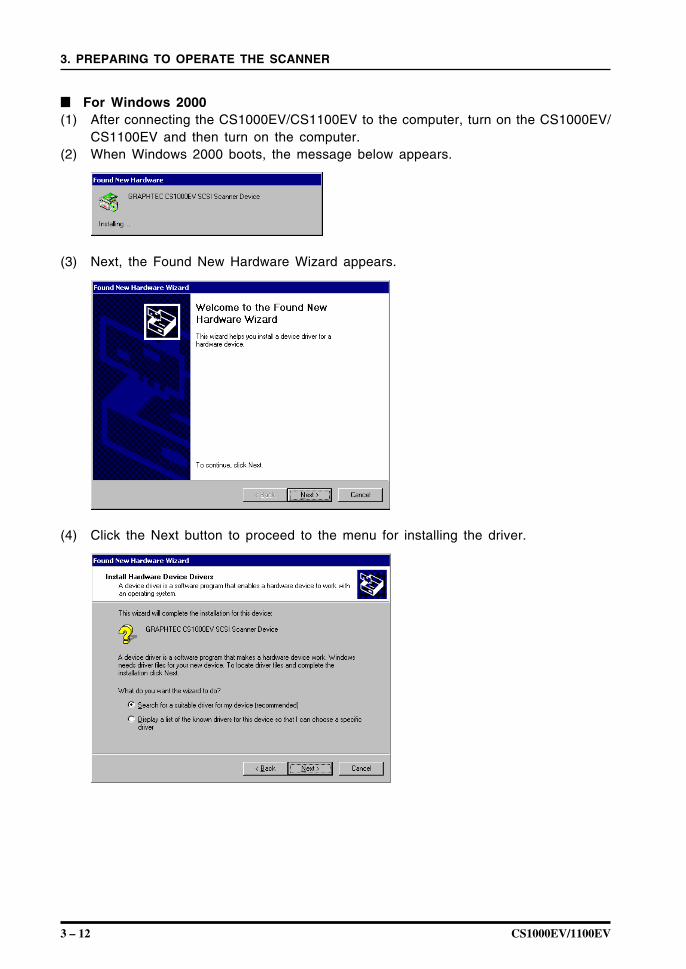
(3) Click on “Next” to search for the driver.(4) Upon completion of the search for the driver, the window shown below is displayed.
Click on the “Finish” button.
(5) The Windows Me desktop is displayed, and the CS1000EV/CS1100EV is recognizedby the computer.
For Windows NT 4.0:(1) After checking that the scanner and the computer are properly connected via the SCSI
interface cable, turn on the scanner first and then turn on the computer.
3 – 12 CS1000EV/1100EV
3. PREPARING TO OPERATE THE SCANNER
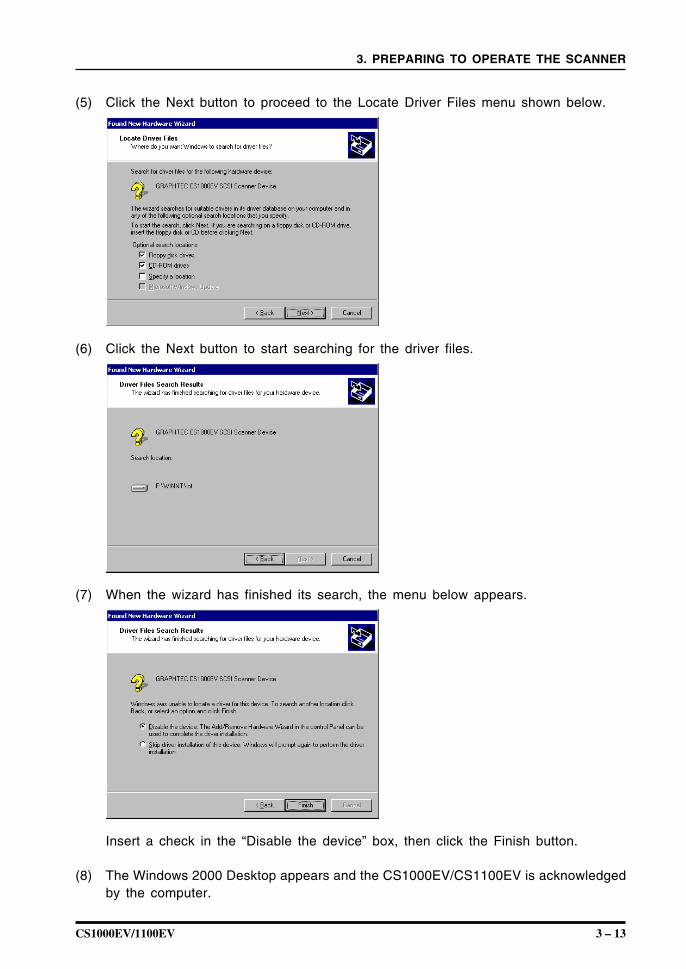
For Windows 2000(1) After connecting the CS1000EV/CS1100EV to the computer, turn on the CS1000EV/
CS1100EV and then turn on the computer.(2) When Windows 2000 boots, the message below appears.
(3) Next, the Found New Hardware Wizard appears.
(4) Click the Next button to proceed to the menu for installing the driver.
CS1000EV/1100EV 3 – 13
3. PREPARING TO OPERATE THE SCANNER
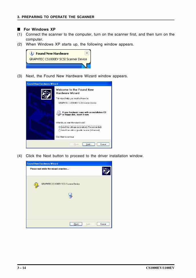
(5) Click the Next button to proceed to the Locate Driver Files menu shown below.
(6) Click the Next button to start searching for the driver files.
(7) When the wizard has finished its search, the menu below appears.
Insert a check in the “Disable the device” box, then click the Finish button.
(8) The Windows 2000 Desktop appears and the CS1000EV/CS1100EV is acknowledgedby the computer.
3 – 14 CS1000EV/1100EV
3. PREPARING TO OPERATE THE SCANNER
For Windows XP(1) Connect the scanner to the computer, turn on the scanner first, and then turn on the
computer.(2) When Windows XP starts up, the following window appears.
(3) Next, the Found New Hardware Wizard window appears.
(4) Click the Next button to proceed to the driver installation window.
CS1000EV/1100EV 3 – 15
3. PREPARING TO OPERATE THE SCANNER
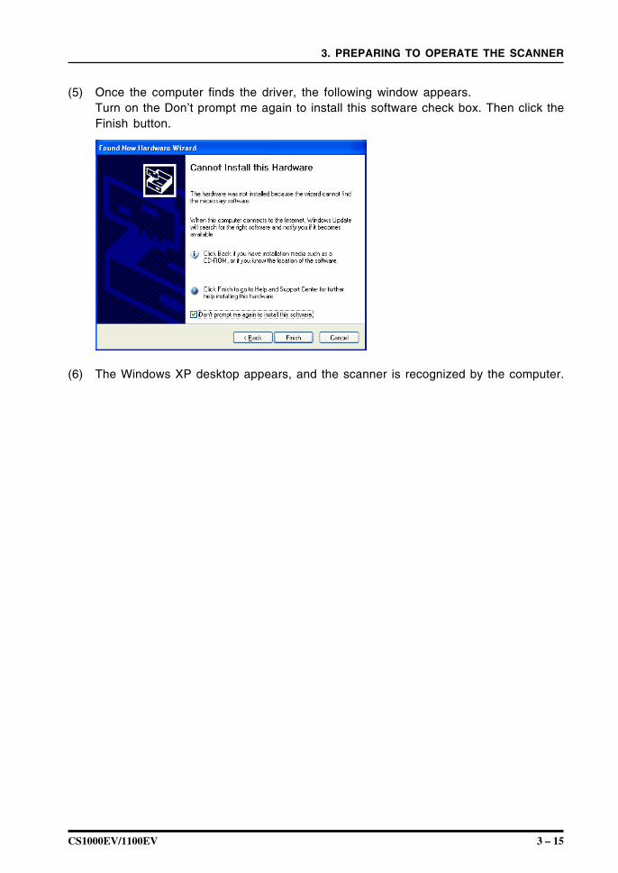
(5) Once the computer finds the driver, the following window appears.Turn on the Don’t prompt me again to install this software check box. Then click theFinish button.
(6) The Windows XP desktop appears, and the scanner is recognized by the computer.
3 – 16 CS1000EV/1100EV
3. PREPARING TO OPERATE THE SCANNER
3.7 Checking the Interface Connection
If the scanner is connected to a system with Adaptec EZ-SCSI DELUXE* installed,the scanner will be recognized under “Scanner” in the Device Manager.* EZ-SCSI DELUXE is the software included with the SCSI adapter. For details, see
the SCSI adapter instruction manual.
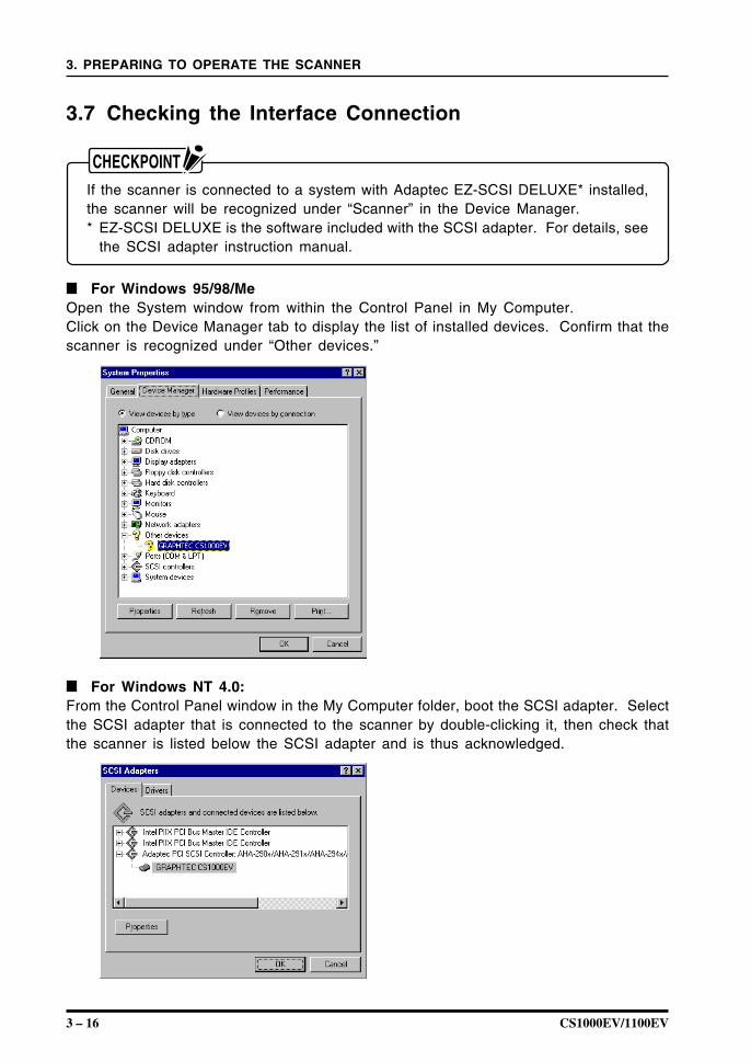
For Windows 95/98/MeOpen the System window from within the Control Panel in My Computer.Click on the Device Manager tab to display the list of installed devices. Confirm that thescanner is recognized under “Other devices.”
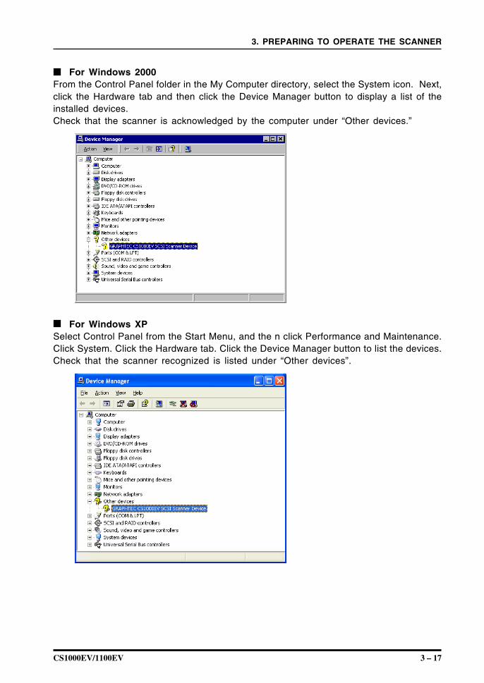
For Windows NT 4.0:From the Control Panel window in the My Computer folder, boot the SCSI adapter. Selectthe SCSI adapter that is connected to the scanner by double-clicking it, then check thatthe scanner is listed below the SCSI adapter and is thus acknowledged.
CS1000EV/1100EV 3 – 17
3. PREPARING TO OPERATE THE SCANNER
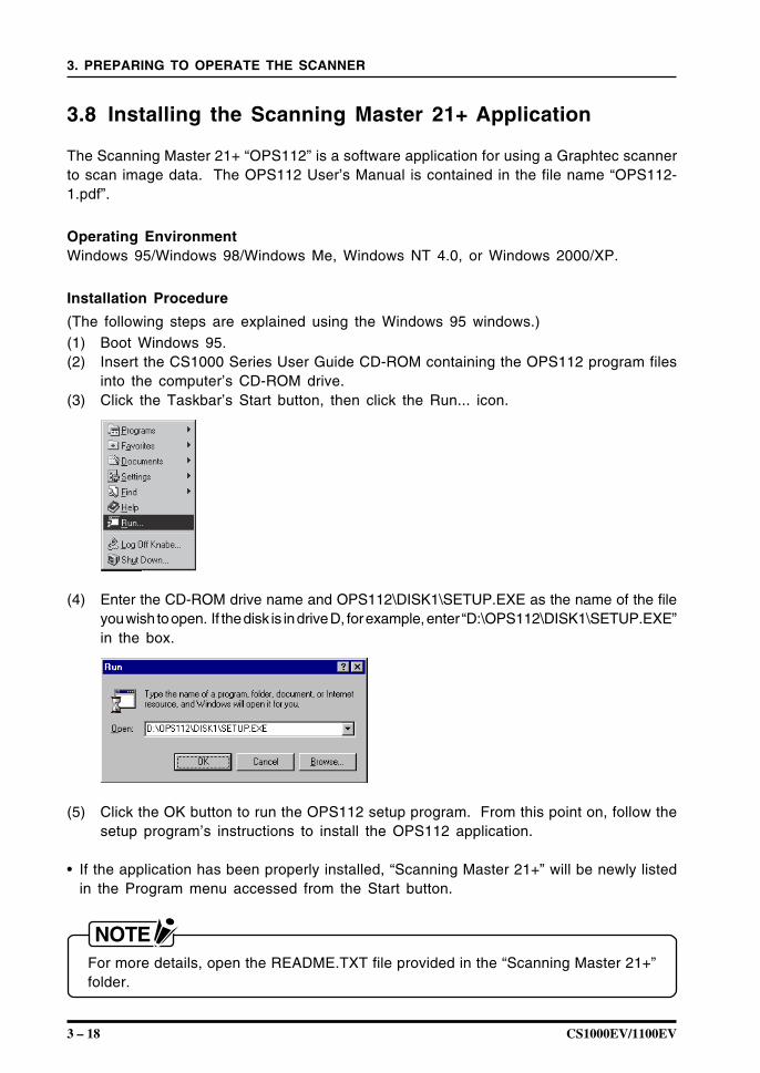
For Windows 2000From the Control Panel folder in the My Computer directory, select the System icon. Next,click the Hardware tab and then click the Device Manager button to display a list of theinstalled devices.Check that the scanner is acknowledged by the computer under “Other devices.”
For Windows XPSelect Control Panel from the Start Menu, and the n click Performance and Maintenance.Click System. Click the Hardware tab. Click the Device Manager button to list the devices.Check that the scanner recognized is listed under “Other devices”.
3 – 18 CS1000EV/1100EV
3. PREPARING TO OPERATE THE SCANNER
3.8 Installing the Scanning Master 21+ Application
The Scanning Master 21+ “OPS112” is a software application for using a Graphtec scannerto scan image data. The OPS112 User’s Manual is contained in the file name “OPS112-1.pdf”.
Operating EnvironmentWindows 95/Windows 98/Windows Me, Windows NT 4.0, or Windows 2000/XP.
Installation Procedure
(The following steps are explained using the Windows 95 windows.)(1) Boot Windows 95.(2) Insert the CS1000 Series User Guide CD-ROM containing the OPS112 program files
into the computer’s CD-ROM drive.(3) Click the Taskbar’s Start button, then click the Run... icon.
(4) Enter the CD-ROM drive name and OPS112\DISK1\SETUP.EXE as the name of the fileyou wish to open. If the disk is in drive D, for example, enter “D:\OPS112\DISK1\SETUP.EXE”in the box.
(5) Click the OK button to run the OPS112 setup program. From this point on, follow thesetup program’s instructions to install the OPS112 application.
• If the application has been properly installed, “Scanning Master 21+” will be newly listedin the Program menu accessed from the Start button.
For more details, open the README.TXT file provided in the “Scanning Master 21+”folder.
CS1000EV/1100EV 3 – 19
3. PREPARING TO OPERATE THE SCANNER
3.9 Installing the Scanning Master Copy Color Application
The Scanning Master Copy Color “OPS116” is a software application for outputting imagedata scanned in by a Graphtec scanner to a plotter or printer.
Operating EnvironmentWindows 95/Windows 98/Windows Me, Windows NT 4.0, or Windows 2000/XP.
Installation Procedure
(The following steps are explained using the Windows 95 windows.)(1) Boot Windows 95.(2) Insert the CS1000 Series User Guide CD-ROM containing the OPS116 program files
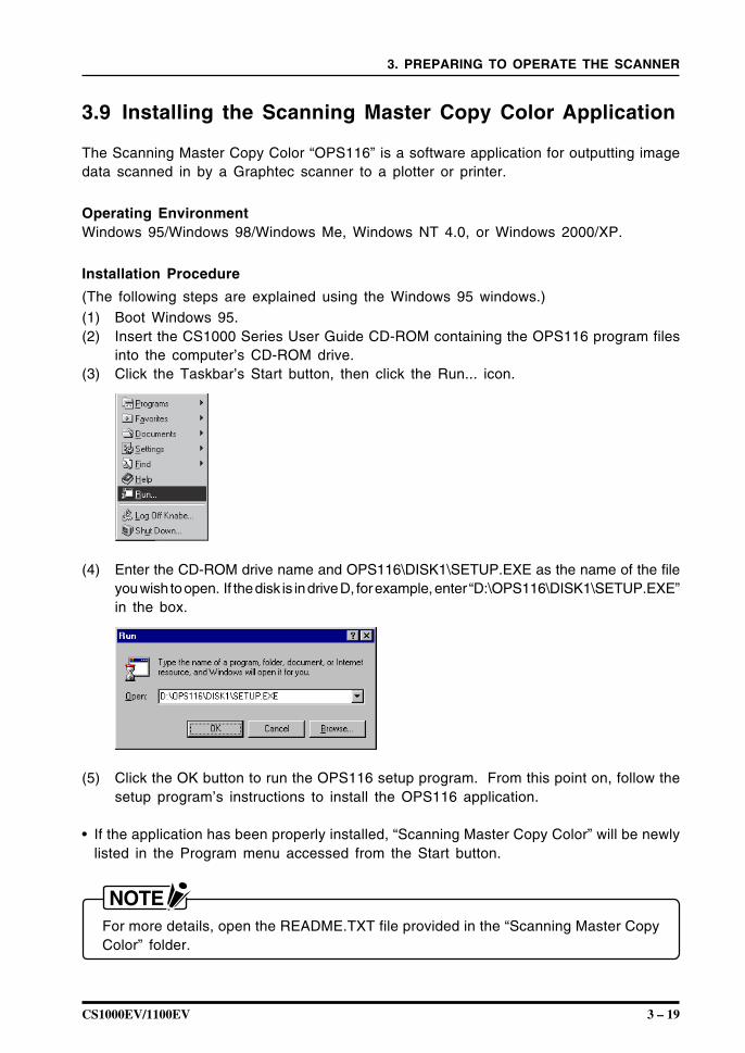
into the computer’s CD-ROM drive.(3) Click the Taskbar’s Start button, then click the Run... icon.
(4) Enter the CD-ROM drive name and OPS116\DISK1\SETUP.EXE as the name of the fileyou wish to open. If the disk is in drive D, for example, enter “D:\OPS116\DISK1\SETUP.EXE”in the box.
(5) Click the OK button to run the OPS116 setup program. From this point on, follow thesetup program’s instructions to install the OPS116 application.
• If the application has been properly installed, “Scanning Master Copy Color” will be newlylisted in the Program menu accessed from the Start button.
For more details, open the README.TXT file provided in the “Scanning Master CopyColor” folder.

3 – 20 CS1000EV/1100EV
3. PREPARING TO OPERATE THE SCANNER
CS1000EV/1100EV 4 – 1
4. LOADING A DOCUMENT
4. LOADING A DOCUMENT
This chapter describes the document types compatible with your scanner and proceduresrelated to loading a document.
4.1 Compatible Document Types
Because the scanner scans a document while feeding it, the document types that it canscan are subject to the following restrictions.
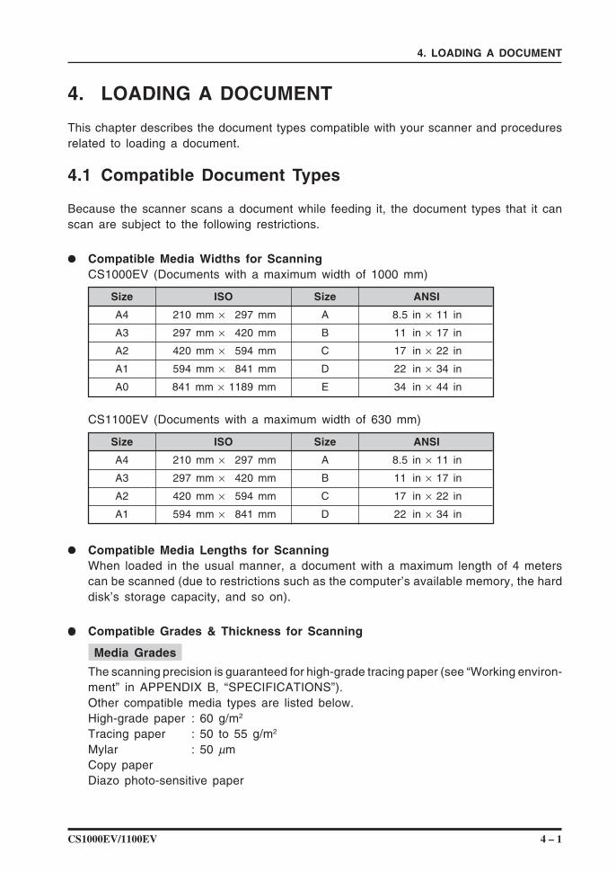
Compatible Media Widths for ScanningCS1000EV (Documents with a maximum width of 1000 mm)
Size ISO Size ANSI
A4 210 mm × 297 mm A 8.5 in × 11 in
A3 297 mm × 420 mm B 11 in × 17 in
A2 420 mm × 594 mm C 17 in × 22 in
A1 594 mm × 841 mm D 22 in × 34 in
A0 841 mm × 1189 mm E 34 in × 44 in
CS1100EV (Documents with a maximum width of 630 mm)
Size ISO Size ANSI
A4 210 mm × 297 mm A 8.5 in × 11 in
A3 297 mm × 420 mm B 11 in × 17 in
A2 420 mm × 594 mm C 17 in × 22 in
A1 594 mm × 841 mm D 22 in × 34 in
Compatible Media Lengths for ScanningWhen loaded in the usual manner, a document with a maximum length of 4 meterscan be scanned (due to restrictions such as the computer’s available memory, the harddisk’s storage capacity, and so on).
Compatible Grades & Thickness for Scanning
Media Grades
The scanning precision is guaranteed for high-grade tracing paper (see “Working environ-ment” in APPENDIX B, “SPECIFICATIONS”).Other compatible media types are listed below.High-grade paper : 60 g/m2
Tracing paper : 50 to 55 g/m2
Mylar : 50 µmCopy paperDiazo photo-sensitive paper

4 – 2 CS1000EV/1100EV
4. LOADING A DOCUMENT
Media Thicknesses
Observe the following points when scanning a thick medium.• The CS1000EV/CS1100EV cannot scan a document that is thicker than 1.5 mm.• When using the carrier sheet, ensure that the combined thickness of both the document
and carrier sheet does not exceed 1.5 mm.• The carrier sheet alone is 0.2 mm thick.
CS1000EV/1100EV 4 – 3
4. LOADING A DOCUMENT
4.2 Loading a Document
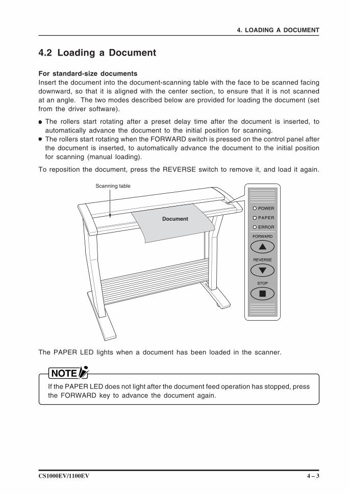
For standard-size documentsInsert the document into the document-scanning table with the face to be scanned facingdownward, so that it is aligned with the center section, to ensure that it is not scannedat an angle. The two modes described below are provided for loading the document (setfrom the driver software).
The rollers start rotating after a preset delay time after the document is inserted, toautomatically advance the document to the initial position for scanning.The rollers start rotating when the FORWARD switch is pressed on the control panel afterthe document is inserted, to automatically advance the document to the initial positionfor scanning (manual loading).
To reposition the document, press the REVERSE switch to remove it, and load it again.
Scanning table
Document
The PAPER LED lights when a document has been loaded in the scanner.
If the PAPER LED does not light after the document feed operation has stopped, pressthe FORWARD key to advance the document again.
4 – 4 CS1000EV/1100EV
4. LOADING A DOCUMENT
After the scanner is turned on and the driver settings have been enabled in the Scanwindow, it waits for approximately two seconds before beginning the specified scanoperation.Load the document in the scanner with the face to be scanned facing downward.Do not place anything other than the document to be scanned on the scanning table,as the scanner rollers may start rotating, which is extremely dangerous.The document may not be fed in correctly if it is curled. The carrier sheet providedshould be used for curled documents (see Section 4.3, “Using the Carrier Sheet” fordetails).Load the document in the center of the scanner, as the document may be fed in atan angle and not scanned correctly if it is significantly off-center.
CS1000EV/1100EV 4 – 5
4. LOADING A DOCUMENT
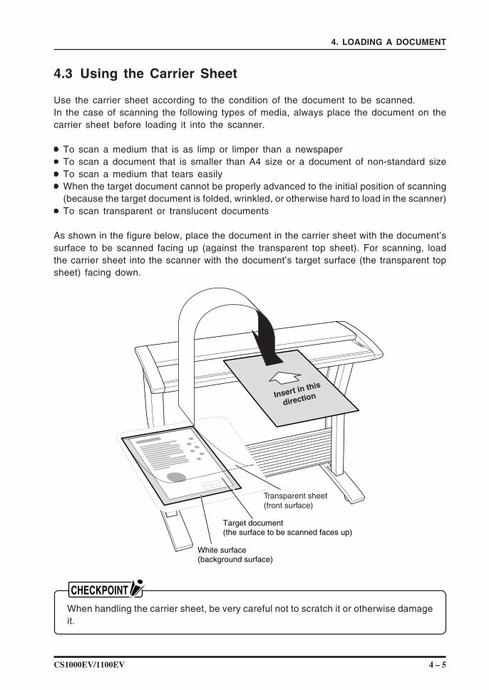
4.3 Using the Carrier Sheet
Use the carrier sheet according to the condition of the document to be scanned.In the case of scanning the following types of media, always place the document on thecarrier sheet before loading it into the scanner.
To scan a medium that is as limp or limper than a newspaperTo scan a document that is smaller than A4 size or a document of non-standard sizeTo scan a medium that tears easilyWhen the target document cannot be properly advanced to the initial position of scanning(because the target document is folded, wrinkled, or otherwise hard to load in the scanner)To scan transparent or translucent documents
As shown in the figure below, place the document in the carrier sheet with the document’ssurface to be scanned facing up (against the transparent top sheet). For scanning, loadthe carrier sheet into the scanner with the document’s target surface (the transparent topsheet) facing down.
Insert in this
direction
Transparent sheet(front surface)
Target document (the surface to be scanned faces up)
White surface (background surface)
When handling the carrier sheet, be very careful not to scratch it or otherwise damageit.
4 – 6 CS1000EV/1100EV
4. LOADING A DOCUMENT
4.4 Using the EV Document Hold-Down Unit
The EV document hold-down unit (the unit with silver handle-rings at the ends) should beused with certain document types as explained below. The EV document hold-down unitis usually mounted on the two stock brackets which are hooked onto the stand’s centerbar (CS1000EV and CS1100EV model mounted on the optional stand). When you wantto use the EV unit, remove the standard document hold-down unit from the scanner, replaceit with the EV unit, and then store the standard unit on the stock brackets instead. If youhave a CS1100EV model without the optional stand, store the document hold-down unit thatis not in use in its original box.
Please use the EV document hold-down unit with the following document types:• Plain paper with a thickness of 0.08 mm or higher• Documents with creases or strongly curled documents where the creases or curl affect
the overall scanning quality
Do not use the EV document hold-down unit with paper less than 0.08 mm thick orwith limp documents, as the document may become damaged or jammed in thescanner. The EV document hold-down unit has a stronger hold-down force than thatof the standard unit, and may cause damage to thin documents. Use the carrier sheetwhen scanning film documents or similar. In addition, because the precision accuracyalso differs, a distance correction operation will need to be performed.
< Distance Correction Method >Distance Correction is performed using the Scanning Master 21+ software. Select AdjustScanner from the Tools menu to correct the distance as appropriate for the type of document.
Replacing the Standard Document Hold-down Unit with the EV Unit
Remove the standard document hold-down unit from the scanner, and replace it with theEV document hold-down unit. For details, please refer to Section 4.5, “Removing theDocument Hold-Down Unit” and Section 4.6, “Mounting the Document Hold-Down Unit” inthis manual.
The handle-rings at both ends of the EV Document hold-down unit are silver. Thehandle-rings at both ends of the standard document hold-down unit are black. Takecare not to confuse the two units.The document hold-down unit has a symmetrical shape, so it is physically possibleto mount it with its left and right sides reversed. Because the scanner’s precision hasbeen adjusted before shipment from the factory, however, the document may jam ifthe unit is mounted in reverse.
CS1000EV/1100EV 4 – 7
4. LOADING A DOCUMENT
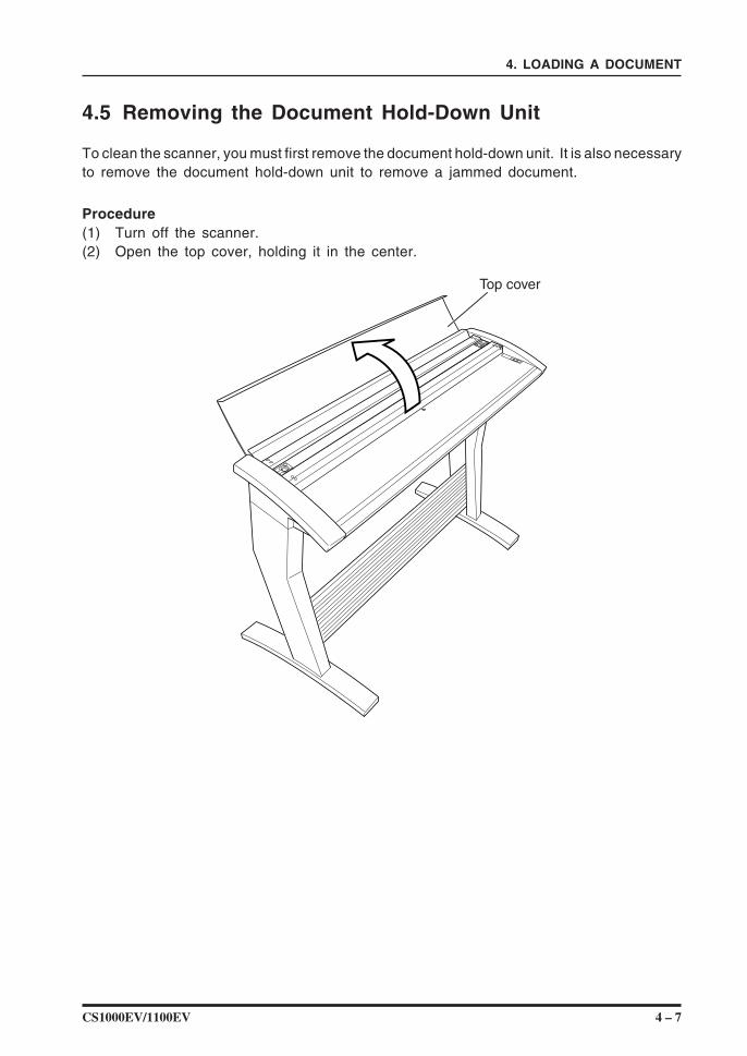
4.5 Removing the Document Hold-Down Unit
To clean the scanner, you must first remove the document hold-down unit. It is also necessaryto remove the document hold-down unit to remove a jammed document.
Procedure(1) Turn off the scanner.(2) Open the top cover, holding it in the center.
Top cover
4 – 8 CS1000EV/1100EV
4. LOADING A DOCUMENT
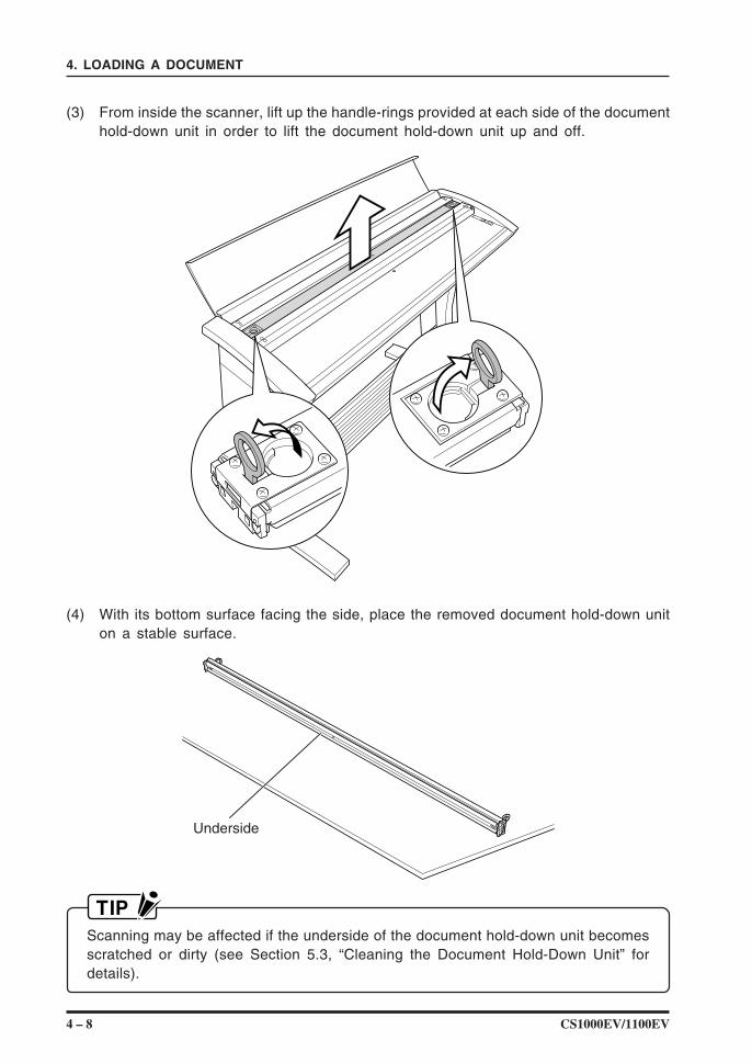
(3) From inside the scanner, lift up the handle-rings provided at each side of the documenthold-down unit in order to lift the document hold-down unit up and off.
(4) With its bottom surface facing the side, place the removed document hold-down uniton a stable surface.
Underside
Scanning may be affected if the underside of the document hold-down unit becomesscratched or dirty (see Section 5.3, “Cleaning the Document Hold-Down Unit” fordetails).
CS1000EV/1100EV 4 – 9
4. LOADING A DOCUMENT
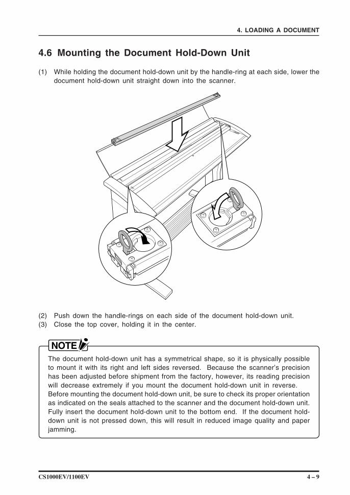
4.6 Mounting the Document Hold-Down Unit
(1) While holding the document hold-down unit by the handle-ring at each side, lower thedocument hold-down unit straight down into the scanner.
(2) Push down the handle-rings on each side of the document hold-down unit.(3) Close the top cover, holding it in the center.
The document hold-down unit has a symmetrical shape, so it is physically possibleto mount it with its right and left sides reversed. Because the scanner’s precisionhas been adjusted before shipment from the factory, however, its reading precisionwill decrease extremely if you mount the document hold-down unit in reverse.Before mounting the document hold-down unit, be sure to check its proper orientationas indicated on the seals attached to the scanner and the document hold-down unit.Fully insert the document hold-down unit to the bottom end. If the document hold-down unit is not pressed down, this will result in reduced image quality and paperjamming.

4 – 10 CS1000EV/1100EV
4. LOADING A DOCUMENT
CS1000EV/1100EV 5 – 1
5. DAILY MAINTENANCE
5. DAILY MAINTENANCE
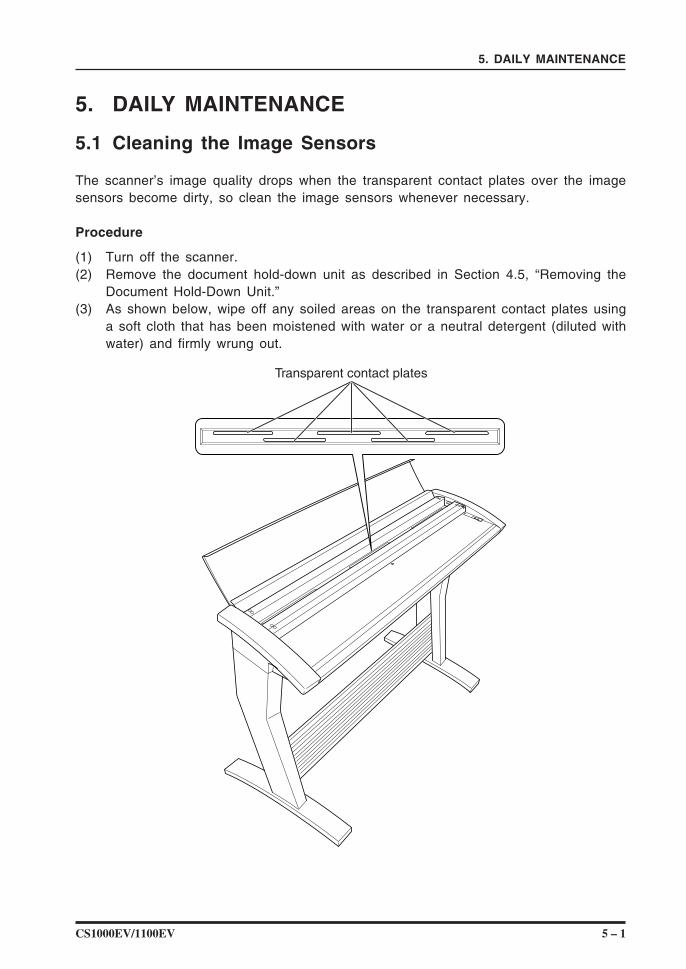
5.1 Cleaning the Image Sensors
The scanner’s image quality drops when the transparent contact plates over the imagesensors become dirty, so clean the image sensors whenever necessary.
Procedure
(1) Turn off the scanner.(2) Remove the document hold-down unit as described in Section 4.5, “Removing the
Document Hold-Down Unit.”(3) As shown below, wipe off any soiled areas on the transparent contact plates using
a soft cloth that has been moistened with water or a neutral detergent (diluted withwater) and firmly wrung out.
Transparent contact plates
5 – 2 CS1000EV/1100EV
5. DAILY MAINTENANCE
(4) Completely remove any moisture on the transparent contact plates by wiping them offagain using a soft, dry cloth.
(5) Mount the document hold-down unit as described in Section 4.6, “Mounting theDocument Hold-Down Unit.”
Do not use a commercial cleaner for office equipment, a glass cleaner, or chemicalsolvents such as solutions containing alcohol.
Although the glass scanning table is not a maintenance part that requires periodicreplacement, it is a consumable part because its surface may receive slight scratchesdue to minute particles of dust and other foreign matter. If document scanning producesunsatisfactory results (unexpected white or black streaks in the data) due to scratcheson the glass table or other reasons, the glass table will be replaced for no chargewhile the service warranty is in effect but will be replaced for a charge after the servicewarranty has expired. To request replacement, contact your nearest Graphtec vendor.
CS1000EV/1100EV 5 – 3
5. DAILY MAINTENANCE
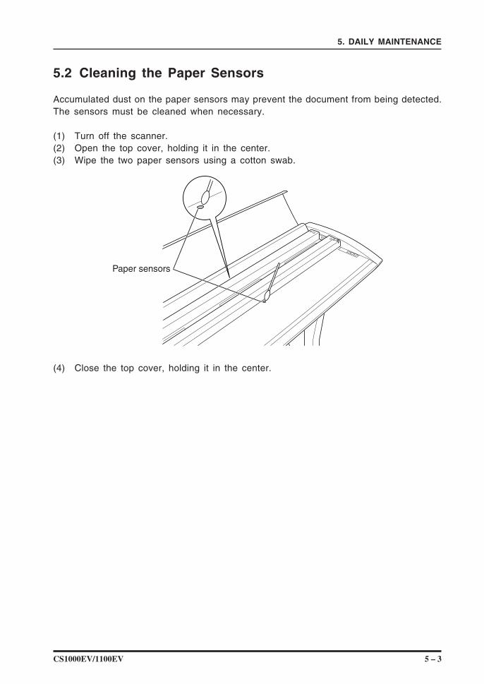
5.2 Cleaning the Paper Sensors
Accumulated dust on the paper sensors may prevent the document from being detected.The sensors must be cleaned when necessary.
(1) Turn off the scanner.(2) Open the top cover, holding it in the center.(3) Wipe the two paper sensors using a cotton swab.
Paper sensors
(4) Close the top cover, holding it in the center.
5 – 4 CS1000EV/1100EV
5. DAILY MAINTENANCE
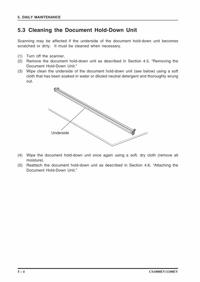
5.3 Cleaning the Document Hold-Down Unit
Scanning may be affected if the underside of the document hold-down unit becomesscratched or dirty. It must be cleaned when necessary.
(1) Turn off the scanner.(2) Remove the document hold-down unit as described in Section 4.5, “Removing the
Document Hold-Down Unit.”(3) Wipe clean the underside of the document hold-down unit (see below) using a soft
cloth that has been soaked in water or diluted neutral detergent and thoroughly wrungout.
Underside
(4) Wipe the document hold-down unit once again using a soft, dry cloth (remove allmoisture).
(5) Reattach the document hold-down unit as described in Section 4.6, “Attaching theDocument Hold-Down Unit.”
CS1000EV/1100EV 5 – 5
5. DAILY MAINTENANCE
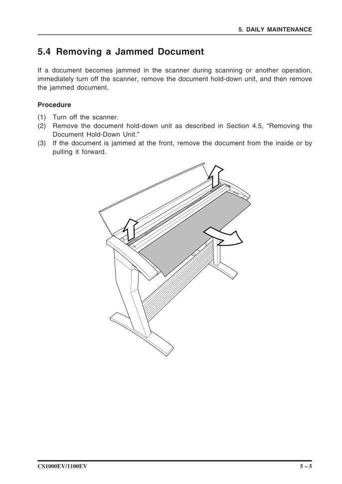
5.4 Removing a Jammed Document
If a document becomes jammed in the scanner during scanning or another operation,immediately turn off the scanner, remove the document hold-down unit, and then removethe jammed document.
Procedure
(1) Turn off the scanner.(2) Remove the document hold-down unit as described in Section 4.5, “Removing the
Document Hold-Down Unit.”(3) If the document is jammed at the front, remove the document from the inside or by
pulling it forward.
5 – 6 CS1000EV/1100EV
5. DAILY MAINTENANCE
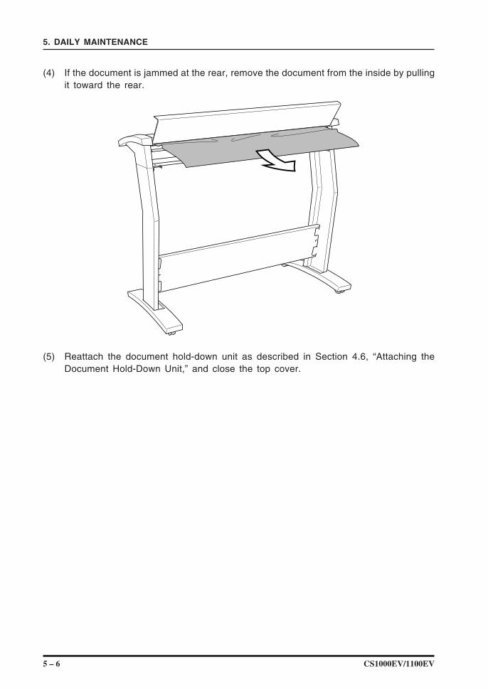
(4) If the document is jammed at the rear, remove the document from the inside by pullingit toward the rear.
(5) Reattach the document hold-down unit as described in Section 4.6, “Attaching theDocument Hold-Down Unit,” and close the top cover.
CS1000EV/1100EV 5 – 7
5. DAILY MAINTENANCE
5.6 Calibration
Calibrate the scanner if scanning quality is observed to deteriorate, with scanned resultssuch as those described below:
The scanned image is distortedAreas of uneven color appear in the scanned imageOther unsatisfactory results (but not including problems related to media quality, suchas folds, wrinkling, or paper curling)
• Handle the calibration sheet with care so that it does not get bent. To prevent soiling,store it in its special storage box. The calibration sheet cannot be used if it is bentor soiled.
• The calibration sheet is a paper product. Do not attempt to clean it with any typeof liquid cleaner.
• The calibration sheet is a consumable item. Replacement sheets can be purchasedfrom your sales representative or nearest Graphtec vendor.
Preparation and checks
Recommended usage environment
Monitor: 1024 × 768 pixels, High Color or better resolution
A low-resolution monitor will make it difficult to discern any problem areas.
Launching the Scanner Adjustment Program
(1) Connect the scanner to the PC and switch on the scanner. Switch on the PC.
(2) Install Scanning Master 21+ (OPS112) if it is not already installed.
(3) Click the Start button, then select Programs > Scanning Master 21+ > ScannerAdjustment.
(4) Click Scanner Adjustment to launch the Scanner Adjustment program.
5 – 8 CS1000EV/1100EV
5. DAILY MAINTENANCE
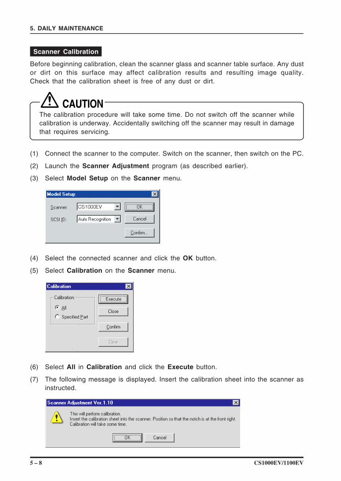
Scanner Calibration
Before beginning calibration, clean the scanner glass and scanner table surface. Any dustor dirt on this surface may affect calibration results and resulting image quality.Check that the calibration sheet is free of any dust or dirt.
The calibration procedure will take some time. Do not switch off the scanner whilecalibration is underway. Accidentally switching off the scanner may result in damagethat requires servicing.
(1) Connect the scanner to the computer. Switch on the scanner, then switch on the PC.
(2) Launch the Scanner Adjustment program (as described earlier).
(3) Select Model Setup on the Scanner menu.
(4) Select the connected scanner and click the OK button.
(5) Select Calibration on the Scanner menu.
(6) Select All in Calibration and click the Execute button.
(7) The following message is displayed. Insert the calibration sheet into the scanner asinstructed.
CS1000EV/1100EV 5 – 9
5. DAILY MAINTENANCE
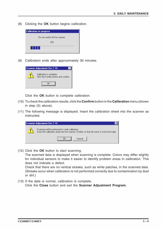
(8) Clicking the OK button begins calibration.
(9) Calibration ends after approximately 30 minutes.
Click the OK button to complete calibration.
(10) To check the calibration results, click the Confirm button in the Calibration menu (shownin step (5) above).
(11) The following message is displayed. Insert the calibration sheet into the scanner asinstructed.
(12) Click the OK button to start scanning.The scanned data is displayed when scanning is complete. Colors may differ slightlyfor individual sensors to make it easier to identify problem areas in calibration. Thisdoes not indicate a defect.Check that there are no vertical streaks, such as white patches, in the scanned data.(Streaks occur when calibration is not performed correctly due to contamination by dustor dirt.)
(13) If the data is normal, calibration is complete.Click the Close button and exit the Scanner Adjustment Program.
5 – 10 CS1000EV/1100EV
5. DAILY MAINTENANCE
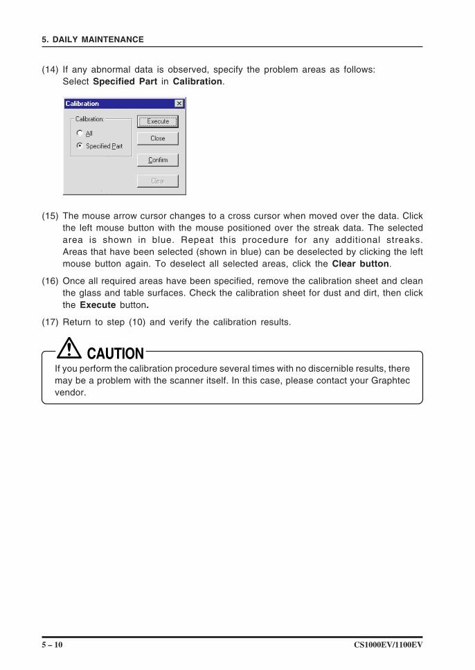
(14) If any abnormal data is observed, specify the problem areas as follows:Select Specified Part in Calibration.
(15) The mouse arrow cursor changes to a cross cursor when moved over the data. Clickthe left mouse button with the mouse positioned over the streak data. The selectedarea is shown in blue. Repeat this procedure for any additional streaks.Areas that have been selected (shown in blue) can be deselected by clicking the leftmouse button again. To deselect all selected areas, click the Clear button.
(16) Once all required areas have been specified, remove the calibration sheet and cleanthe glass and table surfaces. Check the calibration sheet for dust and dirt, then clickthe Execute button.
(17) Return to step (10) and verify the calibration results.
If you perform the calibration procedure several times with no discernible results, theremay be a problem with the scanner itself. In this case, please contact your Graphtecvendor.
CS1000EV/1100EV 6 – 1
6. TROUBLESHOOTING PROCEDURES
6. TROUBLESHOOTING PROCEDURES
If the scanner seems to be operating abnormally, perform the troubleshooting proceduresdescribed in this chapter before requesting a service call.
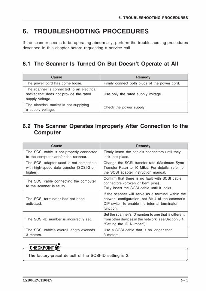
6.1 The Scanner Is Turned On But Doesn’t Operate at All
Cause Remedy
The power cord has come loose. Firmly connect both plugs of the power cord.
The scanner is connected to an electricalsocket that does not provide the rated Use only the rated supply voltage.supply voltage.
The electrical socket is not supplyinga supply voltage.
Check the power supply.
6.2 The Scanner Operates Improperly After Connection to theComputer
Cause Remedy
The SCSI cable is not properly connected Firmly insert the cable’s connectors until theyto the computer and/or the scanner. lock into place.
The SCSI adapter used is not compatible Change the SCSI transfer rate (Maximum Syncwith high-speed data transfer (SCSI-3 or Transfer Rate) to 10 MB/s. For details, refer tohigher). the SCSI adapter instruction manual.
The SCSI cable connecting the computerConfirm that there is no fault with SCSI cable
to the scanner is faulty.connectors (broken or bent pins).Fully insert the SCSI cable until it locks.
If the scanner will serve as a terminal within theThe SCSI terminator has not been network configuration, set Bit 4 of the scanner’sactivated. DIP switch to enable the internal terminator
function.
Set the scanner’s ID number to one that is differentThe SCSI-ID number is incorrectly set. from other devices in the network (see Section 3.4,
“Setting the ID Number”).
The SCSI cable’s overall length exceeds Use a SCSI cable that is no longer than3 meters. 3 meters.
The factory-preset default of the SCSI-ID setting is 2.
6 – 2 CS1000EV/1100EV
6. TROUBLESHOOTING PROCEDURES
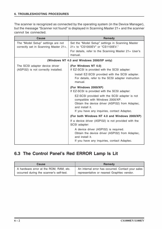
The scanner is recognized as connected by the operating system (in the Device Manager),but the message “Scanner not found” is displayed in Scanning Master 21+ and the scannercannot be connected.
Cause Remedy
The “Model Setup” settings are not Set the “Model Setup” settings in Scanning Mastercorrectly set in Scanning Master 21+. 21+ to “CS1000EV” or “CS1100EV.”
For details, refer to the Scanning Master 21+ User’smanual.
(Windows NT 4.0 and Windows 2000/XP only)
The SCSI adapter device driver (For Windows NT 4.0)(ASPI32) is not correctly installed. If EZ-SCSI is provided with the SCSI adapter:
Install EZ-SCSI provided with the SCSI adapter.For details, refer to the SCSI adapter instructionmanual.
(For Windows 2000/XP)If EZ-SCSI is provided with the SCSI adapter:
EZ-SCSI provided with the SCSI adapter is notcompatible with Windows 2000/XP.Obtain the device driver (ASPI32) from Adaptec,and install it.If you have any inquiries, contact Adaptec.
(For both Windows NT 4.0 and Windows 2000/XP)
If a device driver (ASPI32) is not provided with theSCSI adapter:
A device driver (ASPI32) is required.Obtain the device driver (ASPI32) from Adaptec,and install it.If you have any inquiries, contact Adaptec.
6.3 The Control Panel’s Red ERROR Lamp Is Lit
Cause Remedy
A hardware error at the ROM, RAM, etc. An internal error has occurred. Contact your salesoccurred during the scanner’s self-test. representative or nearest Graphtec vendor.
CS1000EV/1100EV 6 – 3
6. TROUBLESHOOTING PROCEDURES
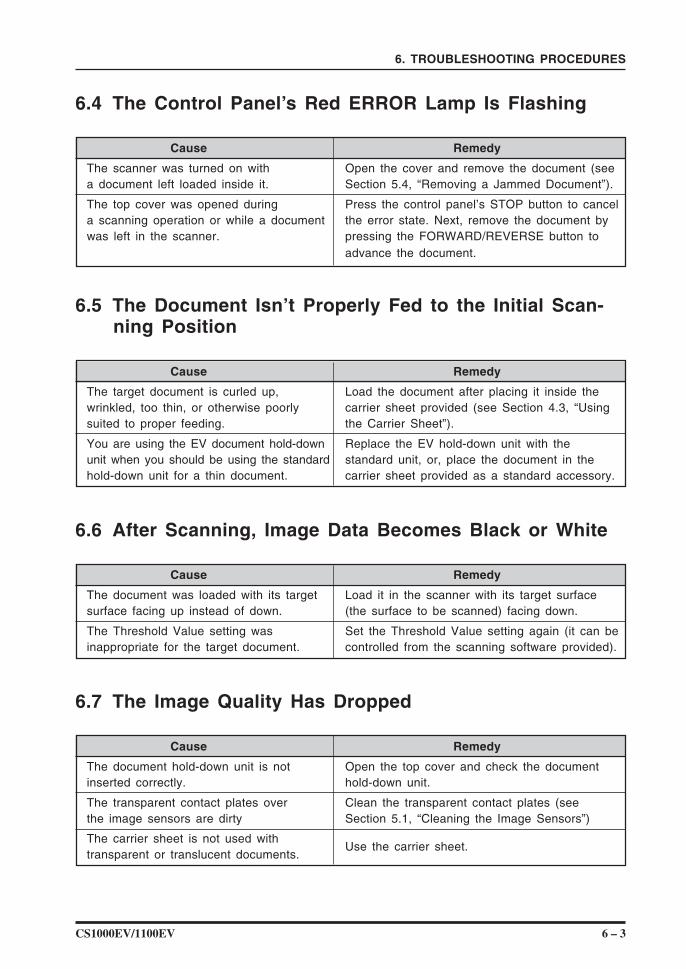
6.4 The Control Panel’s Red ERROR Lamp Is Flashing
Cause Remedy
The scanner was turned on with Open the cover and remove the document (seea document left loaded inside it. Section 5.4, “Removing a Jammed Document”).
The top cover was opened during Press the control panel’s STOP button to cancela scanning operation or while a document the error state. Next, remove the document bywas left in the scanner. pressing the FORWARD/REVERSE button to
advance the document.
6.5 The Document Isn’t Properly Fed to the Initial Scan-ning Position
Cause Remedy
The target document is curled up, Load the document after placing it inside thewrinkled, too thin, or otherwise poorly carrier sheet provided (see Section 4.3, “Usingsuited to proper feeding. the Carrier Sheet”).
You are using the EV document hold-down Replace the EV hold-down unit with theunit when you should be using the standard standard unit, or, place the document in thehold-down unit for a thin document. carrier sheet provided as a standard accessory.
6.6 After Scanning, Image Data Becomes Black or White
Cause Remedy
The document was loaded with its target Load it in the scanner with its target surfacesurface facing up instead of down. (the surface to be scanned) facing down.
The Threshold Value setting was Set the Threshold Value setting again (it can beinappropriate for the target document. controlled from the scanning software provided).
6.7 The Image Quality Has Dropped
Cause Remedy
The document hold-down unit is not Open the top cover and check the documentinserted correctly. hold-down unit.
The transparent contact plates over Clean the transparent contact plates (seethe image sensors are dirty Section 5.1, “Cleaning the Image Sensors”)
The carrier sheet is not used withUse the carrier sheet.
transparent or translucent documents.
6 – 4 CS1000EV/1100EV
6. TROUBLESHOOTING PROCEDURES
Original document Data overlaps
Original document Data is missing
Original document Deviation caused by specifications
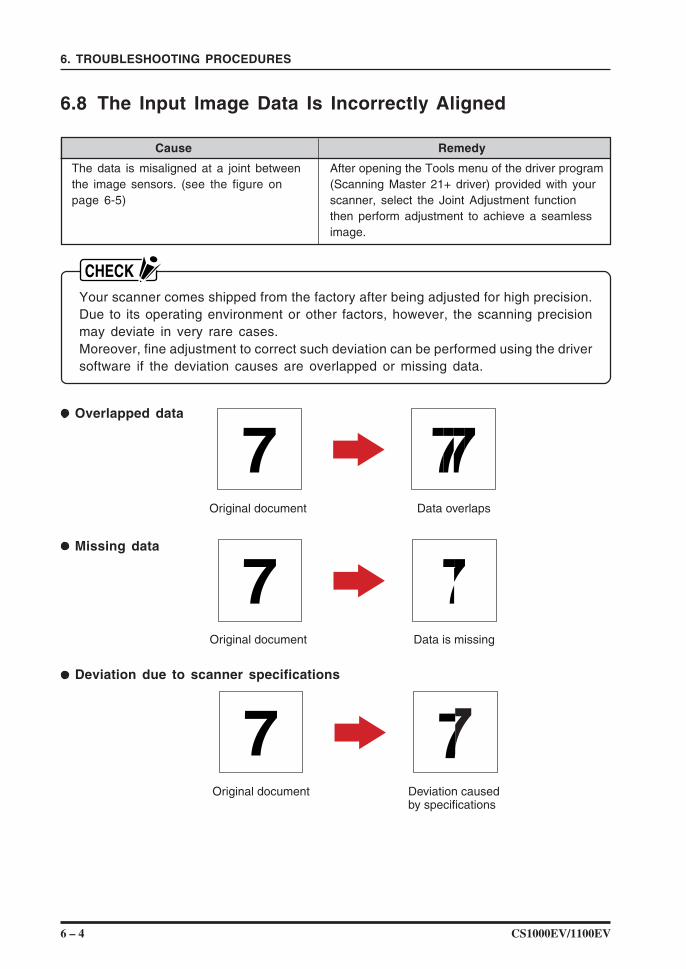
6.8 The Input Image Data Is Incorrectly Aligned
Cause Remedy
The data is misaligned at a joint between After opening the Tools menu of the driver programthe image sensors. (see the figure on (Scanning Master 21+ driver) provided with yourpage 6-5) scanner, select the Joint Adjustment function
then perform adjustment to achieve a seamlessimage.
Your scanner comes shipped from the factory after being adjusted for high precision.Due to its operating environment or other factors, however, the scanning precisionmay deviate in very rare cases.Moreover, fine adjustment to correct such deviation can be performed using the driversoftware if the deviation causes are overlapped or missing data.
Overlapped data
Missing data
Deviation due to scanner specifications
CS1000EV/1100EV 6 – 5
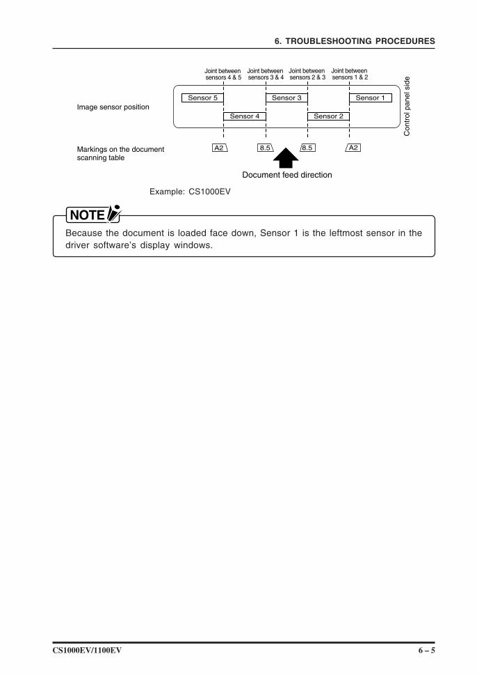
6. TROUBLESHOOTING PROCEDURES
Sensor 5
Sensor 4
Sensor 3
Document feed direction
Markings on the documentscanning table
Con
trol
pan
el s
ide
Sensor 2
Sensor 1
Joint between sensors 4 & 5
Joint between sensors 3 & 4
Joint between sensors 2 & 3
Joint between sensors 1 & 2
A2 8.5 8.5 A2
Image sensor position
Example: CS1000EV
Because the document is loaded face down, Sensor 1 is the leftmost sensor in thedriver software’s display windows.
6 – 6 CS1000EV/1100EV
6. TROUBLESHOOTING PROCEDURES
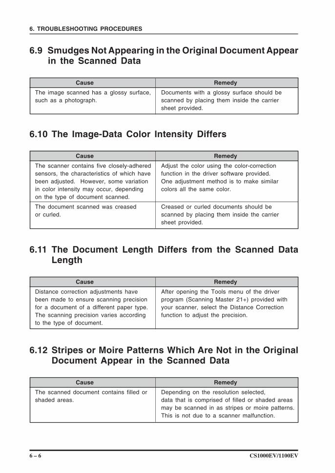
6.9 Smudges Not Appearing in the Original Document Appearin the Scanned Data
Cause Remedy
The image scanned has a glossy surface, Documents with a glossy surface should besuch as a photograph. scanned by placing them inside the carrier
sheet provided.
6.10 The Image-Data Color Intensity Differs
Cause Remedy
The scanner contains five closely-adhered Adjust the color using the color-correctionsensors, the characteristics of which have function in the driver software provided.been adjusted. However, some variation One adjustment method is to make similarin color intensity may occur, depending colors all the same color.on the type of document scanned.
The document scanned was creased Creased or curled documents should beor curled. scanned by placing them inside the carrier
sheet provided.
6.11 The Document Length Differs from the Scanned DataLength
Cause Remedy
Distance correction adjustments have After opening the Tools menu of the driverbeen made to ensure scanning precision program (Scanning Master 21+) provided withfor a document of a different paper type. your scanner, select the Distance CorrectionThe scanning precision varies according function to adjust the precision.to the type of document.
6.12 Stripes or Moire Patterns Which Are Not in the OriginalDocument Appear in the Scanned Data
Cause Remedy
The scanned document contains filled or Depending on the resolution selected,shaded areas. data that is comprised of filled or shaded areas
may be scanned in as stripes or moire patterns.This is not due to a scanner malfunction.
CS1000EV/1100EV A – 1
APPENDIX A. OPTIONAL AND MISCELLANEOUS ITEMS
APPENDIX A. OPTIONAL AND MISCELLANEOUS ITEMS
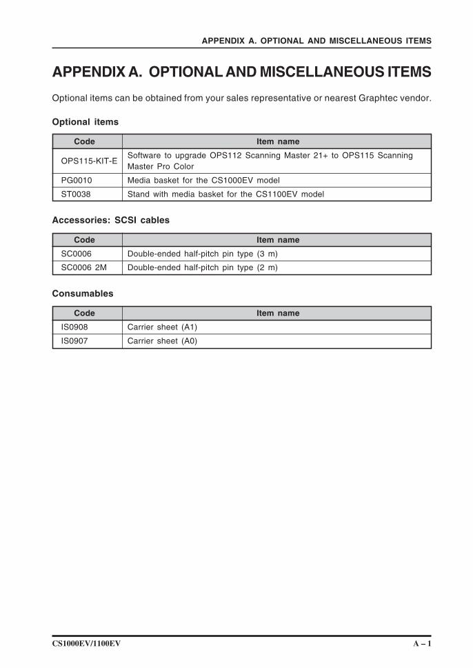
Optional items can be obtained from your sales representative or nearest Graphtec vendor.
Optional items
Code Item name
OPS115-KIT-ESoftware to upgrade OPS112 Scanning Master 21+ to OPS115 ScanningMaster Pro Color
PG0010 Media basket for the CS1000EV model
ST0038 Stand with media basket for the CS1100EV model
Accessories: SCSI cables
Code Item name
SC0006 Double-ended half-pitch pin type (3 m)
SC0006 2M Double-ended half-pitch pin type (2 m)
Consumables
Code Item name
IS0908 Carrier sheet (A1)
IS0907 Carrier sheet (A0)

A – 2 CS1000EV/1100EV
APPENDIX A. OPTIONAL AND MISCELLANEOUS ITEMS
CS1000EV/1100EV B – 1
APPENDIX B. STANDARD SPECIFICATIONS
APPENDIX B. STANDARD SPECIFICATIONS
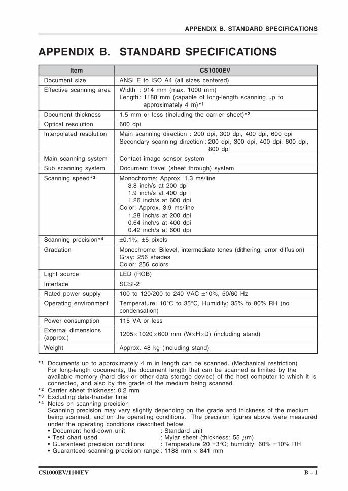
Item CS1000EV
Document size ANSI E to ISO A4 (all sizes centered)
Effective scanning area Width : 914 mm (max. 1000 mm)Length : 1188 mm (capable of long-length scanning up to
approximately 4 m) *1
Document thickness 1.5 mm or less (including the carrier sheet) *2
Optical resolution 600 dpi
Interpolated resolution Main scanning direction : 200 dpi, 300 dpi, 400 dpi, 600 dpiSecondary scanning direction : 200 dpi, 300 dpi, 400 dpi, 600 dpi,
800 dpi
Main scanning system Contact image sensor system
Sub scanning system Document travel (sheet through) system
Scanning speed *3 Monochrome: Approx. 1.3 ms/line3.8 inch/s at 200 dpi1.9 inch/s at 400 dpi1.26 inch/s at 600 dpi
Color: Approx. 3.9 ms/line1.28 inch/s at 200 dpi0.64 inch/s at 400 dpi0.42 inch/s at 600 dpi
Scanning precision *4 ±0.1%, ±5 pixels
Gradation Monochrome: Bilevel, intermediate tones (dithering, error diffusion)Gray: 256 shadesColor: 256 colors
Light source LED (RGB)
Interface SCSI-2
Rated power supply 100 to 120/200 to 240 VAC ±10%, 50/60 Hz
Operating environment Temperature: 10°C to 35°C, Humidity: 35% to 80% RH (nocondensation)
Power consumption 115 VA or less
External dimensions1205 × 1020 × 600 mm (W×H×D) (including stand)
(approx.)
Weight Approx. 48 kg (including stand)
* 1 Documents up to approximately 4 m in length can be scanned. (Mechanical restriction)For long-length documents, the document length that can be scanned is limited by theavailable memory (hard disk or other data storage device) of the host computer to which it isconnected, and also by the grade of the medium being scanned.
* 2 Carrier sheet thickness: 0.2 mm* 3 Excluding data-transfer time* 4 Notes on scanning precision
Scanning precision may vary slightly depending on the grade and thickness of the mediumbeing scanned, and on the operating conditions. The precision figures above were measuredunder the operating conditions described below.• Document hold-down unit : Standard unit• Test chart used : Mylar sheet (thickness: 55 µm)• Guaranteed precision conditions : Temperature 20 ±3°C; humidity: 60% ±10% RH• Guaranteed scanning precision range : 1188 mm × 841 mm
B – 2 CS1000EV/1100EV
APPENDIX B. STANDARD SPECIFICATIONS
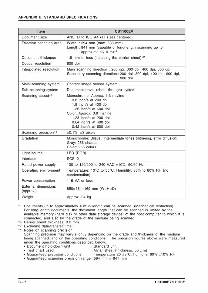
Item CS1100EV
Document size ANSI D to ISO A4 (all sizes centered)
Effective scanning area Width : 594 mm (max. 630 mm)Length : 841 mm (capable of long-length scanning up to
approximately 4 m) *1
Document thickness 1.5 mm or less (including the carrier sheet) *2
Optical resolution 600 dpi
Interpolated resolution Main scanning direction : 200 dpi, 300 dpi, 400 dpi, 600 dpiSecondary scanning direction : 200 dpi, 300 dpi, 400 dpi, 600 dpi,
800 dpi
Main scanning system Contact image sensor system
Sub scanning system Document travel (sheet through) system
Scanning speed *3 Monochrome: Approx. 1.3 ms/line3.8 inch/s at 200 dpi1.9 inch/s at 400 dpi1.26 inch/s at 600 dpi
Color: Approx. 3.9 ms/line1.28 inch/s at 200 dpi0.64 inch/s at 400 dpi0.42 inch/s at 600 dpi
Scanning precision *4 ±0.1%, ±3 pixels
Gradation Monochrome: Bilevel, intermediate tones (dithering, error diffusion)Gray: 256 shadesColor: 256 colors
Light source LED (RGB)
Interface SCSI-2
Rated power supply 100 to 120/200 to 240 VAC ±10%, 50/60 Hz
Operating environment Temperature: 10°C to 35°C, Humidity: 35% to 80% RH (nocondensation)
Power consumption 115 VA or less
External dimensions850× 381× 169 mm (W×H×D)
(approx.)
Weight Approx. 24 kg
* 1 Documents up to approximately 4 m in length can be scanned. (Mechanical restriction)For long-length documents, the document length that can be scanned is limited by theavailable memory (hard disk or other data storage device) of the host computer to which it isconnected, and also by the grade of the medium being scanned.
* 2 Carrier sheet thickness: 0.2 mm* 3 Excluding data-transfer time* 4 Notes on scanning precision
Scanning precision may vary slightly depending on the grade and thickness of the mediumbeing scanned, and on the operating conditions. The precision figures above were measuredunder the operating conditions described below.• Document hold-down unit : Standard unit• Test chart used : Mylar sheet (thickness: 55 µm)• Guaranteed precision conditions : Temperature 20 ±3°C; humidity: 60% ±10% RH• Guaranteed scanning precision range : 594 mm × 841 mm
CS1000EV/1100EV C – 1
APPENDIX C. EXTERNAL VIEW
APPENDIX C. EXTERNAL VIEW
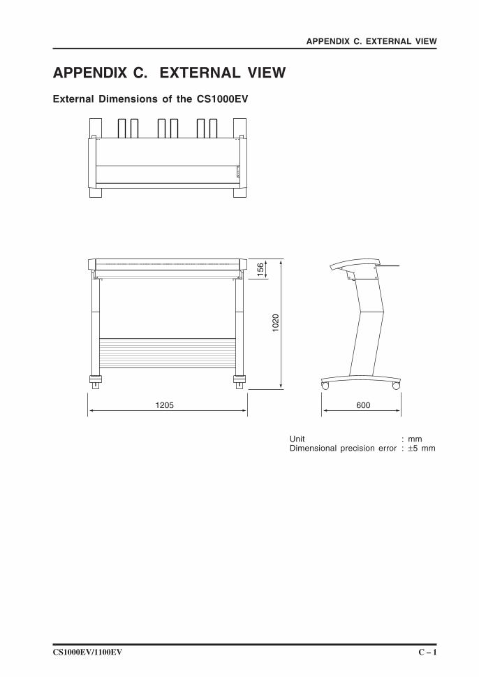
External Dimensions of the CS1000EV
156
1020
1205 600
Unit : mmDimensional precision error : ±5 mm
C – 2 CS1000EV/1100EV
APPENDIX C. EXTERNAL VIEW
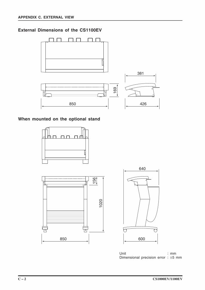
External Dimensions of the CS1100EV
169
850 426
381
When mounted on the optional stand
156
1020
850 600
640
Unit : mmDimensional precision error : ±5 mm
CS1000EV/1100EV Index – 1
INDEX
A
Assembling the scanner (CS1000EV) ...... 2-1
C
Calibration ................................................... 5-7Carrier sheet, using the .............................4-5Caster .......................................................... 2-3Control panel .............................................. 2-4Cover sensor .............................................. 2-3
D
Daily maintenance ...................................... 5-1Daisy-chain .................................................3-3Deviation due to scanner specifications ........................................... 6-4DIP switch ................................................... 2-5Document grade and thickness ................ 4-1Document hold-down unit .......................... 4-7Document hold-down unit, mounting the ... 4-9Document hold-down unit, cleaning the .... 5-4Document hold-down unit, EV............ 2-8, 4-6Document length ........................................ 4-1Document loading operation .....................4-3Document-scanning table .......................... 4-3Document support wire .............................. 2-6Document types ..........................................4-1Document width ..........................................4-1
E
ERROR LED ....................................... 2-4, 6-2EV Document hold-down unit ........... 2-8, 4-6
F
FORWARD key........................................... 2-4
H
Host computer, connecting to the ............ 3-7
I
ID-number setting ....................................... 3-5Image sensors, cleaning the .....................5-1Interface ......................................................1-1
INDEX
M
Missing data ...............................................6-4
O
Overlapped data .........................................6-4
P
Paper jam ................................................... 5-5PAPER LED................................................2-4Paper sensor .............................................. 2-3Paper sensor, cleaning the ....................... 5-3Part Names and Functions ....................... 2-3Power cable, connecting the .....................3-2POWER LED .............................................. 2-4Power switch .............................................. 2-5
R
REVERSE key ............................................ 2-4
S
Scanner, assembling the ........................... 2-1Scanning Master 21+, installing the .......3-18SCSI cable, connecting the ....................... 3-3SCSI connector ..........................................2-5SCSI-ID switch ........................................... 2-5Stand ...........................................................2-3Stock brackets (EV unit) ........................... 2-8STOP key ................................................... 2-4System requirements ................................. 3-1
T
Top cover .................................................... 4-7Transparent contact plates ........................ 5-1Troubleshooting ..........................................6-1
U
Usage precautions ......................................viii
W
Warmup ........................................................viii

The specifications, etc., in this manual aresubject to change without notice.
CS1000-UM-153February 27, 2003 1st edition-01
GRAPHTEC CORPORATION