Embed Size (px)
Citation preview
1
College of Engineering
Department of Mechanical Engineering
Spring Semester 2016-2017
Senior Design Project Report
Design and Build One Person Hovercraft
In partial fulfillment of the requirements for the
Degree of Bachelor of Science in Mechanical Engineering
Team Members
Student Name Student ID
1 Abdullah Al-Muraisel 201100546
2 Meshal Othman 201302079
3 Abdullah AlZahrani 201000170
4 Hussain ALHaider 201300297
5 Mahdi ALmarzoug 201201060
6 Saud Al-Shamsi 201100333
Project Advisors:
Advisor: Dr. Faramarz Djavanroodi Co-Advisor: Dr Nader Sawalhi
2
Abstract
The hovercraft is an important vehicle used for many purposes. It can floats above any
type of ground. Hovercraft sometimes called Air Cushion Vehicle due to its ability to
move by cushion or skirt filled with air and cause the board to hover above the ground,
and it moves by the thrust engine forward and fills up the cushion by lift engine.
In this Project, the aim is to design and manufacture one man hovercraft. It can carry
around 70 kg with rated speed between 5-10 km/h. Two fans are used for this hovercraft,
one of them for thrust and the other one for lift. Each fan has a separate engine to perform
the required task. The thrust engine produce up to 10HP at 3600 RPM and the lift engine
goes up to 6-7HP at 3000 RPM. The dimensions of the hovercraft is 2.4 meter in length
and 1.2 meter in width with 1.00 meter thrust duct diameter. The engine rotation shaft
linked with propeller through hub and pushing. However, the design of the hovercraft
applies a horizontal shaft engine and a vertical shaft engine. The horizontal engine used
for thrust and the vertical engine for lift. The hovercraft is provided with rudders to
control the direction. The whole engine base of the hovercraft is rectangular in shape, and
it can be made of carbon steel or wood. On the other hand, the skirt of the hovercraft
made of PVC Polyester. Finally, our objective to approach a hovercraft with speed range
from 10-15 km/h.
3
Acknowledgment
At this stage of graduation, we would like to extend our hearts to thank Prince
Mohammad Bin Fahad University (PMU) and the distinguished doctors for their efforts
and support in our studies. At the same time, we extend our special thanks and
appreciation to Dr. Faramarz Djavanroodi and Dr. Nader Sawalihi, for their efforts,
continuous guidance, and unparalleled support, are the main ingredients in the
accomplishment of our most important graduation project. Their ever-presence and
continued mentoring is the constituent of our success. Our project, design, and
development of a hovercraft, is unique and required an enormous amount of time and
efforts from the concept to design and construction, and needed continued support,
cooperation and collaboration from team members and doctors. Every team member,
collaborator, and coordinator have put in the maximum during the process and looking
forward for a successful project. Finally, we would like to extend our precaution to Mr.
Fahad Al-Haidar establishment for their support by using their fabrication workshop.
4
Table of Contents
Abstract……………………………………………………………………………………2
Acknowledgments…………………………………………………………………………3
List of Acronyms (Symbols) used in the report:……………………………......................6
List of Figures.………………………………...…………………………………………..7
List of Tables………………………………..…………………………………………….8
Chapter 1: Introduction
1.1 Project Definition…………………...……………………………………………10
1.2 Project Objectives…………………...…………………………………………...11
1.3 Project Specifications …………………...……………………………………….12
Chapter 2: Literature Review
2.1 Project background…………………...………………………………………….14
2.2 Previous Work…………………...………………………………………………15
2.3 Comparative Study…………………...……………………………………….....20
Chapter 3: System Design
3.1 Design Constraints…………………...…………………………………………..26
3.2 Design Methodology…………………...………………………………………..30
3.3 Product Subsystems and Components…………………...………………………39
3.4 Implementation…………………...……………………………………………...43
Chapter 4: System Testing and Analysis
4.1 Subsystem 1…………………...…………………………………………………49
4.2 Subsystem 2…………………...…………………………………………………50
4.3 Overall Results, Analysis and Discussion…………………...…………………..51
5
Chapter 5: Project Management
5.1 Project Plan…………………...…………………..……………………………...55
5.2 Contribution of Team Members…………………...……………………………..61
5.3 Project Execution Monitoring …………………...……………………………….64
5.4 Challenges and Decision Making…………………...…………………………...65
5.5 Project Bill of Materials and Budget…………………...………………………..66
Chapter 6: Project Analysis
6.1 Life-long Learning…………………...……………………………………………68
6.2 Impact of Engineering Solutions…………………...…………………………….68
6.3 Contemporary Issues Addressed…………………...……………………………..70
Chapter 7: Conclusions and Future Recommendations
7.1 Conclusions…………………...………………………………………………….72
7.2 Future Recommendations…………………...…………………………………...73
References…………………...…………………………………………………...74
Appendix A: Progress Reports…………………...………………………………………75
Appendix B: Bill of Materials…………………...……………………………………….96
Appendix C: Operation Manual…………………...……………………………………116

6
List of Acronyms (Symbols)
Air Cushion
Vehicle
A vehicle that floats above any lands such as ice, sand, grass, and water
CAD Computer Aided Design
Skirt Full up with air and it is surrounding around the body.
Base of engine It will carry the engine.
Steering Control the direction.
Rudders Change the air flow direction by using steering.
Thrust duct Design it as a nozzle to increase the flow of air.
Thrust fan Producing flow air.
BHC British Hovercraft Corporation
Aerodynamic Motion of air and gases acting on a body in motion relative to such
Plywood Sheet of layers manufactured by wood.
HP (Horse Power) A unit of foot pound second (fps) to express the mechanical energy.
MDF Medium Density Fiberboard.
RPM Revolution per minute.
LPR Low pressure rubber
HPR High pressure rubber.
7
List of Figures
Figure 1.1 Example of Hovercraft…………………………………………………...…..10
Figure 1.2 Simple explanation of hovercraft………………………………………...…..11
Figure 2.1 First Hovercraft prototype by Christopher Cockerell…………………...……14
Figure 2.2 One Engine Hovercraft………………………………………………...……..15
Figure 2.3 Two Engines Hovercraft…………………………………...………...……….15
Figure 2.4 Distribution of air along the hovercraft…………………………...………….16
Figure 2.5 Hovercraft of another students project…………………………...…………..22
Figure 3.1 Using a Hovercraft for RESCUE…………………………...………………..29
Figure 3.2 The sketch of thrust duct…………………………...………………………...33
Figure 3.3 Components of Hovercraft……………………………………...……………39
Figure 3.4 Skirt of Hovercraft……………………………………………...…………….41
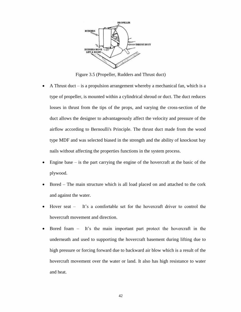
Figure 3.5 Propeller, Rudders and Thrust duct………...……………...…………………42
Figure 3.6 Exploded View SoildWork………………………………...……...………….44
Figure 4.1 Measurement Tools…………………………...……………………………...50
Figure 4.2 Vibration velocity of the engine and base of the engine…………………......52
Figure 4.3 Vibration acceleration of the engine and base of the engine ………………...53
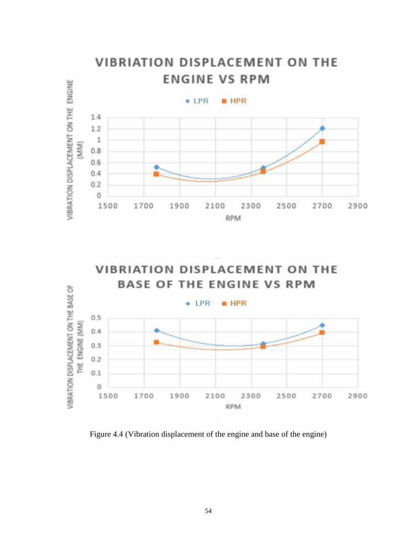
Figure 4.4 Vibration displacement of the engine and base of the engine………………..54

8
List of Tables
Table 3.1 Recommended Design Specifications ……….........……………………….....27
Table 3.2 Specifications based on Factors……………...…………………………….….30
Table 3.3 volume rate and percent of error…………...………………………………….35
Table 3.4 Thrust duct Calculation………………...……………………………………...35
Table 3.5 Velocity of Air…………………………...……………………………………37
Table 3.6 Components of Hovercraft…………...…………………………………….….39
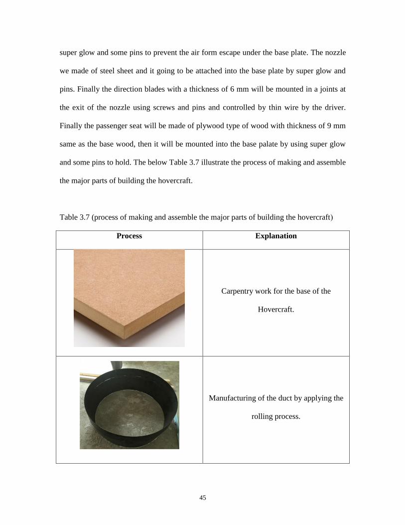
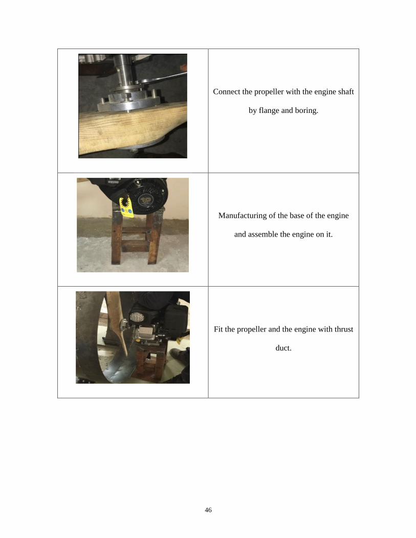
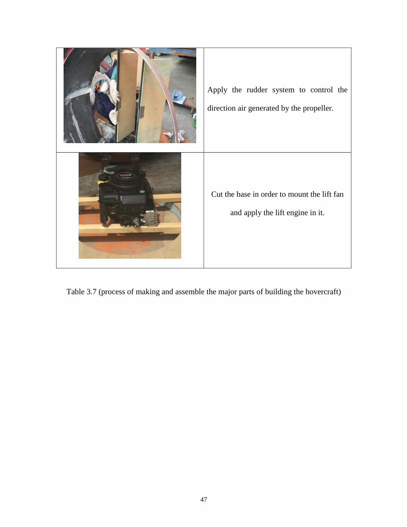
Table 3.7 Process of making and assemble the major parts of building the hovercraft…45
Table 4.1 Thrust duct Calculation………………...……………………………………..49
Table 4.2 Actual testing result using the proper equipment at 1770 RPM………………55
Table 4.3 Actual testing result using the proper equipment at 2370 RPM………………56
Table 4.4 Actual testing result using the proper equipment at 2700 RPM………………57
Table 5.1 Project's time frame…….…………...…………………………………….…..59
Table 5.2 Work Plan …...………………………………………………………………..61
Table 5.3 Task Distribution…………………...….………………………………….…..62
Table 5.4 Project Budget……………………...………………………………………….66

9
CHAPTER 1
INTRODUCTION
1.2 PROJECT OBJECTIVES
1.3 PROJECT SPECIFICATIONS
1.1 PROJECT DEFINITION

10
1.1 Project Definition:
Figure 1.1 (Example of Hovercraft)
A Hovercraft is a vehicle that floats above any lands such as ice, sand, grass, and water.
Hovercraft sometimes called Air Cushion Vehicle due to its ability to move by cushion or
skirt filled with air and cause the board to hover above the ground, and by the thrust
engine it runs forward and fills up the cushion as shown in figure 1.1. In this project, we
intended to build and design our hovercraft which could work in many circumstances as
much as the car regarding any land. The concept of the hovercraft is simple, starts with a
particular kind of wood that has the property in carrying loads and has some gaps to help
wood floats above any land. Underneath the wood, the skirt or cushion takes place, and it
functions to create a change in pressure bycatch the air in one area to create the required
difference in pressure between inside and outside of the skirt. The mechanical part of our
project is the engine and control system which help in maneuvering and monitoring the
direction of the hovercraft. The project is helpful and necessary many cases such as
military and security in which hovercraft are excellent for off beach protection and
rescue. For commercial operation also hovercraft can play a distinct role in guiding the
ships to the shore safely and efficiently rather than using small boats which can cost a lot

11
in maintenance. The best application of the hovercraft comes in situations like flooded
areas like what happened in al-Khobar city a few weeks ago. The figure 1.2 explains the
simple mechanism of hovercraft.
Figure 1.2 (Simple explanation of hovercraft)
1.2 Project Objectives:
The hovercraft project went into different phases and challenges to approach the
following objectives:
I. Prototype a Hovercraft with simple design and can do the required function of
movement.
II. The approach design of hovercraft is to move with a rated speed of 10-15 km/h.
III. Hovercraft can tolerate with more weight up to 200 kg and runs under intensive
operation smoothly.
IV. Improve the factor of safety for all materials during all operation process.
V. Propagate new vision for a vehicle can operate in different circumstances.
12
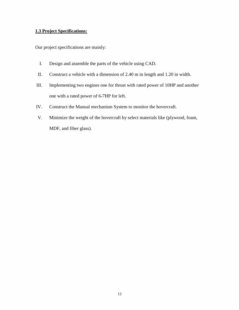
1.3 Project Specifications:
Our project specifications are mainly:
I. Design and assemble the parts of the vehicle using CAD.
II. Construct a vehicle with a dimension of 2.40 m in length and 1.20 in width.
III. Implementing two engines one for thrust with rated power of 10HP and another
one with a rated power of 6-7HP for left.
IV. Construct the Manual mechanism System to monitor the hovercraft.
V. Minimize the weight of the hovercraft by select materials like (plywood, foam,
MDF, and fiber glass).
13
CHAPTER 2
LITERATURE REVIEW
2.2 PREVIOUS WORK
2.3 COMPARATIVE STUDY
2.1 PROJECT BACKGROUND
14
2.1 Project Background:
The first hovercraft was concocted and protected by the English innovator Christopher
Cockerell, in 1952 and figure 2.1 shows the first prototype. A few innovators preceding
that date had fabricated or endeavored to manufacture vehicles given the "ground effect"
rule (the possibility that catching air between a fast moving vehicle and the ground can
give additional lift and decrease drag). These endeavors were of restricted achievement
and did not utilize the annular air pad that known today. The initial design for hovercraft
was gotten from a British development in the 1950s to 1960s.
Figure 2.1 (First Hovercraft prototype by Christopher Cockerell)
They are presently utilized all through the world as accurate transports in misfortune
alleviation, coastguard, military and study applications and also for game or traveler
benefit. Large forms have been utilized to transport individuals and vehicles over the
English Channel, while others have military applications used to carry tanks, fighters and
expensive hardware in antagonistic situations and landscape. Although now a non-
exclusive term for the kind of specialty, the name Hovercraft itself was a trademark
possessed by Saunders-Roe (later British Hovercraft Corporation (BHC), then Westland),
subsequently other producers' utilization of option names to portray the vehicles. [1, 2]
15
Some hovercraft has two motors with two arrangements of controls for lifting and thrust
as figure 2.3 and some hovercrafts do ( lift and thrust ) by one engine as figure 2.2 , the
only engine outline parts air lessening the requirement for two motors, to spare weight
and disentangle operation. Left and right bearing are overseen by steering to control
rudders into the back of the fan channel get together. Some hovercraft have a high focus
of gravity and can be hard to guide around corners; like a car like which lowers center of
gravity that helps cornering.[3]
Figure 2.2 (One Engine Hovercraft)
Figure 2.3 (Two Engines Hovercraft)
2.2 Previous Work:
A hovercraft, otherwise called an air-cushion vehicle or ACV, is a specialty equipped
for going over land, water, mud, ice, and different surfaces. Hovercrafts are half vessels
worked by a pilot as a flying machine as opposed to a chief as a marine vessel. A
hovercraft is a land and water capable vehicle that is bolstered by a pad of marginally
16
pressurized air. Although regularly observed as a secretive, even unusual method of
transportation, it is reasonably straightforward. To see how hovercraft functions, it is
important to understand that the progression is more firmly identified with airship than to
boats and automobiles. As an individual from a group of air pad vehicles (ACVs) or
Ground Effect Machines, which incorporates wing-in-ground-impact or ram wings,
surface impact ships, sidewall hovercraft ship and surface skimmers, hovercraft are the
land and water capable individuals from the air pad vehicle family. They are the most
novel among vehicles that are bolstered by pressurized air. Allude to the delineation
underneath as presented that how precisely hovercraft functions.
Figure 2.4 (Distribution of Air Along the hovercraft)
As in (figure 2.4); Hovercraft glides on a pad of air that has been constrained under the
specialty by a fan. This causes the hovercraft to rise or lift. The measure of lift can run
from 6" to 108" (152mm to 2,743mm) contingent upon the extent of hovercraft. The
measure of aggregate weight that a hovercraft can raise is equivalent to pad weight
duplicated by the zone of the hovercraft. To make the specialty work all the more
effectively, it is important to restrict the pad air from getting away, so the air is contained
by the utilization of what is known as a hovercraft skirt. Formed from texture, which
allows a thick cushion or clearance of obstacles, hovercraft skirts shift in style extending
17
from packs to cells to isolate fingered areas called fragments.
Once "lifted" or "on the cushion," push must be made to propel the hovercraft. With
many specialties, this is produced by a different motor from the one used to make the lift,
yet with a few, a similar motor is utilized for both. The fan-produced air stream is the
part, so that piece of the air is coordinated under the body for lift, while a significant
portion of it is utilized for pushed. Since the hovercraft has lift and push, it must be
controlled securely. This is accomplished using an arrangement of rudders behind the fan,
controlled by handlebars in advance. Directing can likewise be controlled by the
utilization of body weight dislodging, an aptitude which is accomplished after practice.
Hovercraft utilizes blowers to deliver a large volume of air underneath the frame that is
somewhat above air weight. The weight distinction between the higher pressure air
underneath the frame and lower weight encompassing air above it produces lift, which
causes the body to skim over the running surface. For dependability reasons, the air is
commonly blown through openings or gaps around the outside of a slots or holes giving
most hovercraft a trademark adjusted rectangle shape. Often this pad is contained inside
an adaptable "skirt," which permits the vehicle to go over little checks without harm.
Small hovercraft has a developing part to play in pursuit and protect business and military
operations around the globe. Hovercraft can be a down to earth recommendation for
operations in zones out of reach to different vehicles including solidified water, mud
pads, intertidal regions, shallow streams and overflowed inland regions.
Hovercraft has at least one separate motor (some hovercraft, for example, the SR-N6,
have one motor with a drive split through a gearbox). One motor drives the fan (the
impeller) which is in charge of lifting the vehicle by compelling air under the hovercraft.

18
The air in this manner must exit all through the "skirt," lifting the art over the territory on
which the craft resides. At least one extra motor is utilized to give push keeping in mind
the end goal to drive the specialty in the fancied course. Some hovercraft use ducting to
permit one engine to perform both errands, by guiding a portion of the air to the skirt,
whatever remains of the air going out of the back to push craft forwards.[4]
Hover work of Parry Sound planned to improve the situation of the hovercraft rudder,
which utilizes a hybrid and skirt outline that consolidates the best of routine hovercraft
innovations. The Air Rider Hovercraft is proposed to defeat a portion of the shortcomings
of the two most basic hovercraft plans. The air pad of a hovercraft is delivered by an
adaptable elastic or plastic skirt that hangs down from the structure. The skirt should be
sufficiently flexible to hold noticeable all around, yet sufficiently adaptable to permit the
art to arrange rugged landscape, waves, and low impediments. This settles on the
selection of skirts somewhat of a bargain, with the two primary options showing
unmistakable qualities and shortcomings. The first is loop skirt, which, as the name
suggests, encloses the hull of the craft. The compressor lift fan blows air under the body
where the circle catches it, shaping a cushion and lifting the craft. It's an effective plan.
The loop skirt is great at making and keeping up the air pad, yet on water, it makes for an
incredibly rough ride with heaps of shower and drag. As per Hover work, Air-Rider
hovercraft split the contrast between the two skirts by method for a loop/segment hybrid
design. The sides and stern are secured by a loop skirt, and the bow has a fragmented
skirt. This eliminates the splash and slamming as the fragmented bow respects
approaching waves, while the circuit gives greater security and to a lesser degree an
inclination to catch. Hover-works says that the plan likewise improves the Air-Rider
19
much then either customary outline at arranging stony stream beds or waterway rapids.
[5]
Sir John Thornycroft was a British architect who in the 1870s started to test his
hypothesis that delay a ship's structure could be diminished if a ship had a plenum
chamber, basically an empty box, open at the base. He imagined that if the chamber could
be pumped brimming with air, the ship would skim over the water and move quicker
because there would be less resistance. He wasn’t able to prove that how to keep the "air
pad" from getting away from under the craft. Cockerell throws away the plenum load
guideline, guessing rather that if he could pump air under the vessel through a limited
space that circled it, the air would stream toward the vessel's middle, in this manner
shaping an outer blind that would trap the rise of air under the hull. Cockerell trusted this
framework, which got to be distinctly known as a peripheral jet, would permit the boat to
hover. He petitioned for a patent in late 1955, and the following year shaped Hovercraft
Ltd. In 1959, he propelled the principal down to earth air pad vehicle, the SR-N1. It had
an elastic skirt that contained the air pad over harsh terrains or water. This model crossed
the English Channel in June 1959. It had a top speed of 10 mph and couldn't arrange
rushes of more than 18 inches or land hindrances higher than a foot. [6]
20
2.3 Comparative Study:
1/ Indiana State University’s Society of Manufacturing Engineers (SME) and Society of
Automotive Engineer (SAE) have teamed up to build a hovercraft. The students hope to
enter a few races in the fall of 2004.[7] With encouragement from Chris Fitzgerald,
founder of the World Hovercraft Organization and president of Neoteric Hovercraft, Inc.,
in Terre Haute, the ISU team has spent long hours planning, designing and building their
hovercraft from a material kit purchased from Universal Hovercraft in Harvard, Ill. The
materials package the ISU team is using consists of plywood, foam, fiberglass, epoxy,
contact cement, PVC-coated nylon, a propeller, an aluminum hub, a ten horsepower
Tecumseh engine, and screws and pulleys.
The purchase of the kit was made possible by a donation of $1,060 from the local parent
chapter of SME 275. The local chapter 275 has been a big supporter of the ISU student
chapter 089.
A team of 15 ISU students began working on the Hovercraft project in January 2004.
“A lot of SME guys are graduating, and we wanted to do something before we were
gone,” Dave Oelschlager, a senior from Columbia City, Ind., said.
The students downloaded a set of hovercraft blueprints from www.DiscoverHover.org,
the website of the World Hovercraft Organization’s International School Hovercraft
Program, which provides hovercraft plans and instructions at no charge to students,
schools and youth organizations. The ISU team then began a redesign of the original
blueprints.
According to Oelschlager, who is heavily involved in the project, the redesigning of the
21
blueprints took well over 70 hours of volunteer work. Through the use of AutoCAD and
Pro-E, junior high and high school students can easily understand the new blueprints.
Rob Wilson, Neoteric Hovercraft’s Technical Director in Australia, is currently
reviewing the new plans for accuracy.
“ISU is playing a key role in taking the Discover-Hover Build-a-Hovercraft School
Project to schools and students throughout the world by creating a prototype project for
the program and improving the original plans,” said the marketing director for Neoteric
Hovercraft and the World Hovercraft Organization.
James Smallwood, chairperson and professor of manufacturing/construction technology
and Mike Hayden, professor of industrial/mechanical technology, serve as advisers to the
students.
“When an organization does a project like this, it gives students additional real-life,
problem-solving skills,” Smallwood said. “They are not only doing the work; they are
managing a project. We’ve learned that all else being equal, a manager who has
experience in the technology behind a project is a better manager than one who does not
have that experience, we’re preparing managers.”
Hovercraft operate by floating on a cushion of air over land, water, ice, and mud.
“They’re very environmentally friendly, with little impact,” Herring continued. “A
hovercraft can be flown over a nest of bird’s eggs without harming them."
22
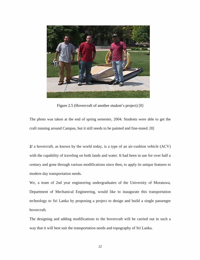
Figure 2.5 (Hovercraft of another student’s project) [8]
The photo was taken at the end of spring semester, 2004. Students were able to get the
craft running around Campus, but it still needs to be painted and fine-tuned. [8]
2/ a hovercraft, as known by the world today, is a type of an air-cushion vehicle (ACV)
with the capability of traveling on both lands and water. It had been in use for over half a
century and gone through various modifications since then, to apply its unique features to
modern day transportation needs.
We, a team of 2nd year engineering undergraduates of the University of Moratuwa,
Department of Mechanical Engineering, would like to inaugurate this transportation
technology to Sri Lanka by proposing a project to design and build a single passenger
hovercraft.
The designing and adding modifications to the hovercraft will be carried out in such a
way that it will best suit the transportation needs and topography of Sri Lanka.

23
The project will be conducted under the supervision of,
● Dr. Palitha Dasanayake (Head of Department – Mechanical Engineering)
● Dr. Nirosh Jayaweera (Senior lecturer)
● Mr. Sasiranga De Silva (Lecturer)
As engineering undergraduates of DOME UoM, Our goal is to conduct a study on
Hovercraft technology and ultimately design and manufacture a cost effective working
model, using the knowledge and skills of the finest undergraduate talent in the island and
the facilities of our very own country.
Objectives:
● To design and build a hovercraft to be presented to the exhibitions.
● To analyze the potential capabilities of designing and building hovercrafts locally and
to assess the advantages of such a conveyance to Sri Lanka.
● To identify potential research areas related to hovercraft technology and implement
upon completion of the project.
● To introduce an energy-efficient way of travelling and search for other utilities of
implementing this technology.
● To understand the applications of basic engineering principles learnt as a mechanical
engineering student and to improve professional and teamwork skills.
● To get hands on experience with various manufacturing methods and engineering
tools.
24
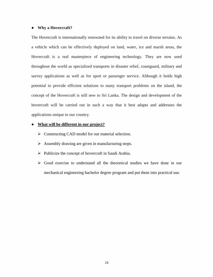
● Why a Hovercraft?
The Hovercraft is internationally renowned for its ability to travel on diverse terrains. As
a vehicle which can be effectively deployed on land, water, ice and marsh areas, the
Hovercraft is a real masterpiece of engineering technology. They are now used
throughout the world as specialized transports in disaster relief, coastguard, military and
survey applications as well as for sport or passenger service. Although it holds high
potential to provide efficient solutions to many transport problems on the island, the
concept of the Hovercraft is still new to Sri Lanka. The design and development of the
hovercraft will be carried out in such a way that it best adapts and addresses the
applications unique to our country.
● What will be different in our project?
➢ Constructing CAD model for our material selection.
➢ Assembly drawing are given in manufacturing steps.
➢ Publicize the concept of hovercraft in Saudi Arabia.
➢ Good exercise to understand all the theoretical studies we have done in our
mechanical engineering bachelor degree program and put them into practical use.

25
CHAPTER 3
SYSTEM DESIGN
3.2 DESIGN METHODOLOGY
3.3 PRODECT SUBSYSTEMS AND
COMPONENTS
3.1 DESIGN CONSTRAINTS
3.4 IMPLEMENTATION

26
3.1 Design Constraints:
The hovercraft is a vehicle that is used in land, water, river, snow, ice...etc. The most
important for the hovercraft is the designing to have the successful result. You need your
CAD drawing to be applied to help your hovercraft structure. Before the designing
process of hovercraft began, the following points should be consider in designing of
hovercraft:-
● The engine, horse power, torque, and rpm.
● The full size and weight of hovercraft body.
● Thrust duct design.
● The material for the hovercraft.
● The air channel to the skirt.
● The maximum load for hovercraft.
These are some of the important factors which one needs to consider for designing a
hovercraft. Material selection is very important. The CAD drawing should be exactly
correct and near to reality to help you make your hovercraft successfully. The sizing and
measuring for (height, weight, length) are essential to run-up your assembly in
SOLIDWORKS program. Also, we can test the properties of materials in the lab. When
the length, for example, is not accurate with the weight of the engines and total body
which been designing, this might affect the balance of the hovercraft. Our hovercraft
project recommended design specification shown in (Table 3.1):
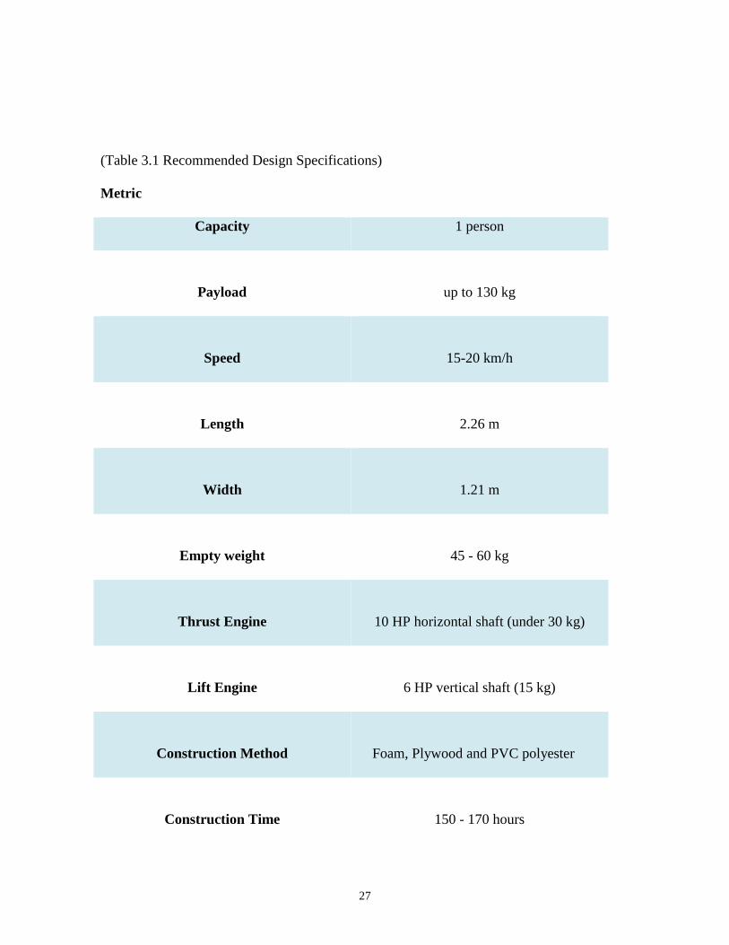
27
(Table 3.1 Recommended Design Specifications)
Metric
Capacity 1 person
Payload
up to 130 kg
Speed
15-20 km/h
Length
2.26 m
Width
1.21 m
Empty weight
45 - 60 kg
Thrust Engine
10 HP horizontal shaft (under 30 kg)
Lift Engine
6 HP vertical shaft (15 kg)
Construction Method
Foam, Plywood and PVC polyester
Construction Time
150 - 170 hours
28
The payload is the lifting capacity of the hovercraft. There are two sorts of payload, the
ground weight lift ability, and the on-water weight lift capacity. Hovercraft for the most
part lift half more weight when beginning ashore, a few providers fudge their on-water
ability, so it doesn’t depend on the number of seats the hovercraft have. We must check
the on-water lift capacity on the off chance that you plan to go over and stop or need, to
begin with, water. At the point when hovercraft begin on water, the hovercraft makes a
weight wave known as the Hump – now and then difficult to get over and get to be
distinctly airborne. We can delineate the protuberance by pushing a bit of paper on a
work area while binding it with another discovered the paper curves up like a wave.
Getting over mound is harder to do in shallow water.
The feasibility of utilizing hovercraft for marine protection has less fluid resistance
comparing with (i.e. ships and pontoons). So, the organization can easily perform their
job by reaching the enemy as an example. The Improvement of coastal safeguard
effectiveness will in the long run. The quantity of security units that should be sent to
keep up seaside resistance and the capacity to move arrive based landscape alongside
maritime floors. In fact, we trust that hovercraft are the most reasonable specialties to be
utilized for sea protection and in whatever another area. It won't just enhance resistance
and security in the local, however, will decrease the expenses on marine defense having
an effect on the overall defense budget. The hovercraft is useful for island areas. Many of
the islands are difficult to reach by aircraft because of the small size of the area. It is not
far away from the cities, so the hovercraft is one of the appropriate solutions for
transportation.

29
Figure 3.1 (Using a Hovercraft for RESCUE)
Using the hovercraft for rescuing people from ship sinking or helps people for emergency
cases as in figure 3.1. So, the hovercraft can take the forces or any other helpers quickly
to that islands because it does not need for the port construction. The military used the
hovercraft to coach those people who try to use the sea border to escape from country or
Smuggling of contraband into the country. One of the most used and it is an official for
hovercraft. It has used to explore for unexploded bombs. The hovercraft is more safely
than the boat in many areas that have stones which can damage the fan used in the boat.
In the other hand, hovercraft does not have the fan as the boat. The fan is on the top
which cannot touch the floor. The hovercraft is more safety to use it in many areas that
any other vehicles cannot go. Also, the bottom of the hovercraft is not made of carbon
steel or material that can be corroded. It is made by PVC polyester which is under all of
the hovercraft with fewer prices than other material. If any problem happened with the
skirt as damage. It can be easily fixed or changed because as it is not expensive.

30
3.2 Design Methodology:
Before the designing process of hovercraft began, we determined the most important
principles to structure our hovercraft. We consider the following points as criteria
guidance:
• Availability of materials.
• Good performance.
• Economical.
The performance of hovercraft is depend on the material selection and function for each
part. Materials and parts were selected based on their availability and easy to use in repair
and maintenance when facing problem. The main principle governing process was the
guide line to achieve our aim for successful project. The most important factor is
minimize the friction between the hovercraft structure and the ground. On other hand,
material cost played a large factor on hovercraft designing. After that, we determined the
type and specifications of the hovercraft designing based on factors below (Table 3.2):
(Table 3.2 Specifications based on Factors)
Factors Factor Priority Description
Lift
High
Minimize friction between hovercraft
and floor
Lift skirt
Essential
Generate air cushion in the skirt
Speed control
Essential
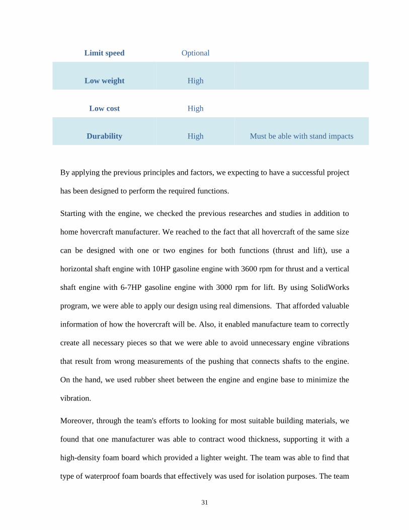
31
Limit speed Optional
Low weight
High
Low cost
High
Durability
High
Must be able with stand impacts
By applying the previous principles and factors, we expecting to have a successful project
has been designed to perform the required functions.
Starting with the engine, we checked the previous researches and studies in addition to
home hovercraft manufacturer. We reached to the fact that all hovercraft of the same size
can be designed with one or two engines for both functions (thrust and lift), use a
horizontal shaft engine with 10HP gasoline engine with 3600 rpm for thrust and a vertical
shaft engine with 6-7HP gasoline engine with 3000 rpm for lift. By using SolidWorks
program, we were able to apply our design using real dimensions. That afforded valuable
information of how the hovercraft will be. Also, it enabled manufacture team to correctly
create all necessary pieces so that we were able to avoid unnecessary engine vibrations
that result from wrong measurements of the pushing that connects shafts to the engine.
On the hand, we used rubber sheet between the engine and engine base to minimize the
vibration.
Moreover, through the team's efforts to looking for most suitable building materials, we
found that one manufacturer was able to contract wood thickness, supporting it with a
high-density foam board which provided a lighter weight. The team was able to find that
type of waterproof foam boards that effectively was used for isolation purposes. The team

32
checked the chemical properties of the material obtained to adjust measurements and
calculations of weights and durability. On the other hand, the martial used for the skirt
was the hardest challenge of the project. However, the team, through written
communications, reached valuable chemical properties of PVC polyester, the martial
used for skirt building which is also used for tent manufacture.
Thrust duct is the most critical part of a hovercraft. It was important to learn about past
experiments of thrust duct designs. Thus, the strategy used for designing thrust duct is to
use nozzle shaped like wooden boards. The design was completed through SolidWorks
program. It depended on using foam spray with a wooden object then it is arranged in the
figure attached.
Through searching the designs and functions of mechanism in the previous hovercraft,
we gained valuable information on the mechanism of hovercraft. Thrust air increases in
power because of the nozzle-shaped thrust duct. Air produced is divided into two
divisions; one is used for motion of a craft while the other division of air is compressed
and pushed through a duct under the craft to lift it with the help of the skirt.
33
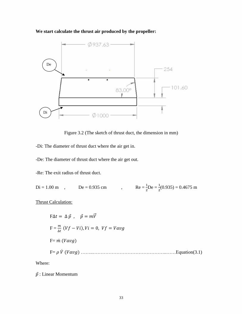
We start calculate the thrust air produced by the propeller:
Figure 3.2 (The sketch of thrust duct, the dimension in mm)
-Di: The diameter of thrust duct where the air get in.
-De: The diameter of thrust duct where the air get out.
-Re: The exit radius of thrust duct.
Di = 1.00 m , De = 0.935 cm , Re = 1
2De =
1
2(0.935) = 0.4675 m
Thrust Calculation:
F∆𝑡 = ∆ �⃗� , �⃗� = 𝑚�⃗⃗�
F = 𝑚
∆𝑡 (𝑉𝑓 − 𝑉𝑖), 𝑉𝑖 = 0, 𝑉𝑓 = 𝑉𝑎𝑣𝑔
F= 𝑚 ̇ (𝑉𝑎𝑣𝑔)
F= 𝜌 �̇� (𝑉𝑎𝑣𝑔) ……..………………………………………..……Equation(3.1)
Where:
�⃗� : Linear Momentum
Di
De
34
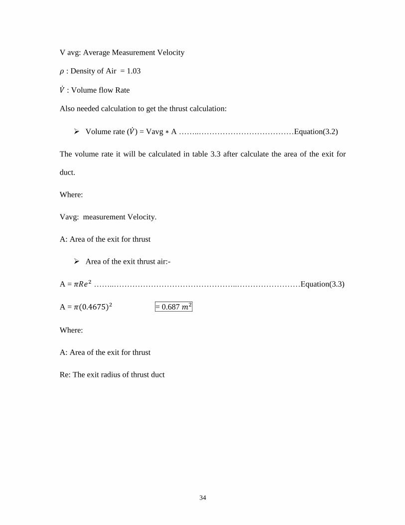
V avg: Average Measurement Velocity
𝜌 : Density of Air = 1.03
�̇� : Volume flow Rate
Also needed calculation to get the thrust calculation:
➢ Volume rate (�̇�) = Vavg ∗ A ……..………………………………Equation(3.2)
The volume rate it will be calculated in table 3.3 after calculate the area of the exit for
duct.
Where:
Vavg: measurement Velocity.
A: Area of the exit for thrust
➢ Area of the exit thrust air:-
A = 𝜋𝑅𝑒2 ……..………………………………………..……………………Equation(3.3)
A = 𝜋(0.4675)2 = 0.687 𝑚2
Where:
A: Area of the exit for thrust
Re: The exit radius of thrust duct
35
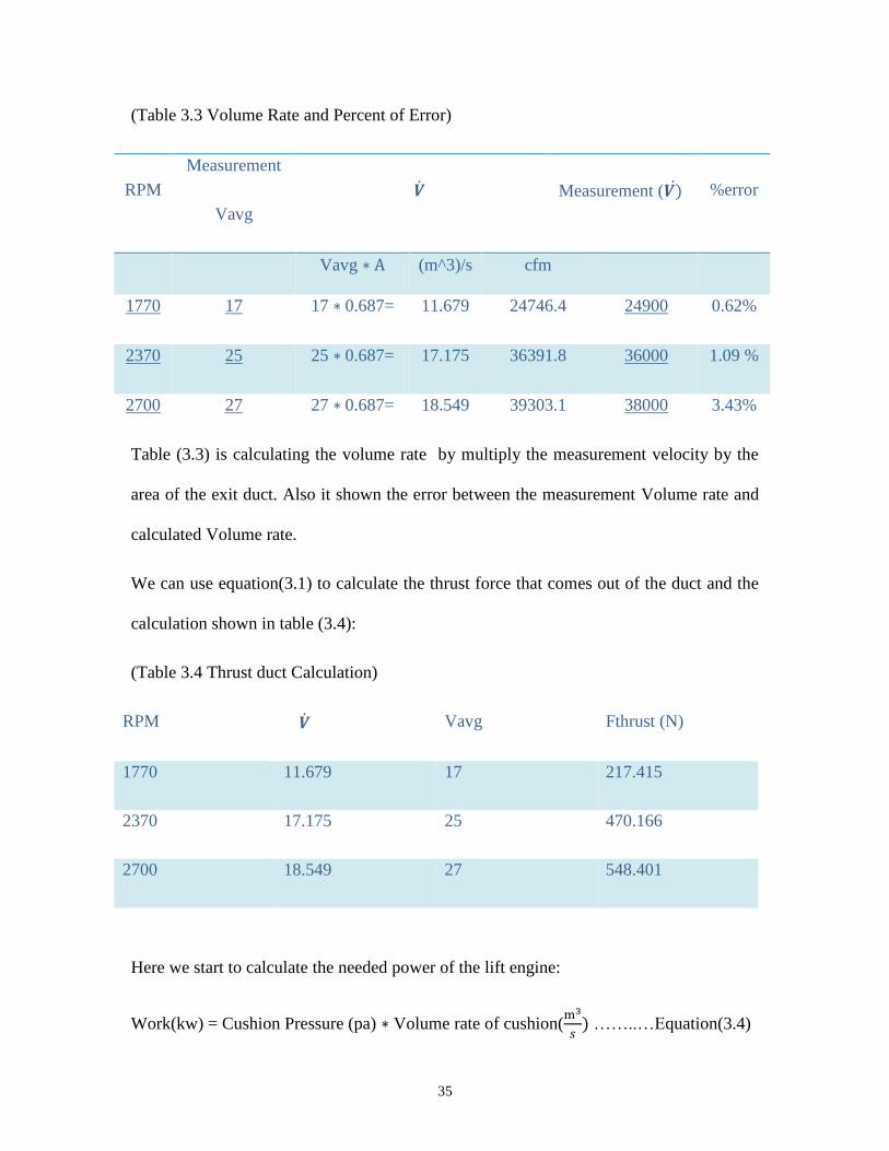
(Table 3.3 Volume Rate and Percent of Error)
RPM
Measurement
Vavg
�̇� Measurement (𝑽)̇ %error
Vavg ∗ A (m^3)/s cfm
1770 17 17 ∗ 0.687= 11.679 24746.4 24900 0.62%
2370 25 25 ∗ 0.687= 17.175 36391.8 36000 1.09 %
2700 27 27 ∗ 0.687= 18.549 39303.1 38000 3.43%
Table (3.3) is calculating the volume rate by multiply the measurement velocity by the
area of the exit duct. Also it shown the error between the measurement Volume rate and
calculated Volume rate.
We can use equation(3.1) to calculate the thrust force that comes out of the duct and the
calculation shown in table (3.4):
(Table 3.4 Thrust duct Calculation)
RPM �̇� Vavg Fthrust (N)
1770 11.679 17 217.415
2370 17.175 25 470.166
2700 18.549 27 548.401
Here we start to calculate the needed power of the lift engine:
Work(kw) = Cushion Pressure (pa) ∗ Volume rate of cushion(m3
𝑠) ……..…Equation(3.4)

36
We start with needed data to end up with all needed for calculation.
#First needed is the Cushion Pressure in (pa):
Length = 2.4 m ,Width = 1.2 m , Gross Mass = 200 kg
➢ Cushion Pressure (pa) = Gross weight (N)
Cushion Area ……..…………………..…Equation(3.5)
o Gross weight (N) = mg …………………………………Equation(3.6)
Gross weight (N) = 200∗ 9.81 = 1962 N
o Cushion Area = Length ∗ Width …………………………...Equation(3.7)
Cushion Area = 2.4 ∗ 1.2 = 2.88 𝑚2
Cushion pressure: the pressure comes out from the base of hovercraft.
Gross weight: the total weight of hovercraft including the person.
Cushion area: the total area of hovercraft which is length multiply by width.
After calculating the gross weight and cushion area we can use them in equation(3.5) to
calculate the cushion pressure:
➢ Cushion Pressure (pa) = 𝟏𝟗𝟔𝟐
𝟐.𝟖𝟖 = 681.25 pa
#Second needed is the Volume rate of cushion in (m3
𝑠):
➢ Volume rate of cushion(m3
𝑠)
= Total Hover Gap Area ∗ Velocity of Air(m3
𝑠) ………………………..Equation(3.8)
o Total Hover Gap Area = Lift Parameter ∗ Airgap…………..Equation(3.9)
37
Total hover gap area: is the total area that the air comes out under the hovercraft.
▪ Lift Parameter = (2 ∗ Legth) + (2 ∗ Width) ………Equation(3.10)
= (2 ∗ 2.4) + ( 2 ∗ 1.2) = 7.2 m
The lift parameter means the total parameter of the hovercraft which added all sides of
hovercraft.
▪ Airgap: is the space between the hovercraft and the ground which
is = 0.008 m
Now we can calculate the total hove gap area from equation(3.8):
o Total Hover Gap Area = 7.2 m * 0.008m = 0.576𝑚2
Table 3.5 is calculating the Velocity of Air (m3
𝑠):
We need to calculate our 𝛼 to know what is our velocity of air on the fixed table that can
helps to know how much velocity of air you need:
𝛼 = Gross Mass (kg)
Cushion Area …………………………………………………………..Equation(3.11)
Our 𝛼 = 200
2.88 = 69.444
(Table 3.5 Velocity of Air )
𝜶
Velocity of Air (𝐦 𝐬⁄ ) Minimum ×𝟏𝟎−𝟔 Maximum ×𝟏𝟎−𝟔
0 8.787 0
8.787 43.933 14.265
38
43.933 57.992 17.556
57.992 79.080 20.300
79.080 96.654 22.494
96.654 114.227 24.689
114.227 131.801 26.700
131.801 149.374 28.529
➢ Volume rate of cushion(m3
𝑠)= Total Hover Gap Area ∗ Velocity of Air(
m3
𝑠) =
0.0576 ∗ 20.300 = 1.1693 (m3
𝑠)
To convert the (Volume rate of cashion) from (𝑚3
𝑠) to (cfm)
use the following equation:-
Volume rate of cushion(cfm) = Volume rate of cushion(𝑚3
𝑠) ∗ 2118.88
Work = [ Cushion Pressure (pa) ∗ Volume rate of Cushion ] ……….……..Equation(3.12)
To get the work in (kw), You need to multiply the answer by (10−3)
Also, you need dived it by the Coefficient fraction of fan which is = (0.593)
Work(kw) = [ 681.25 (pa) ∗ 1.1693(𝑚3
𝑠) ] ∗
10−3
0.593 = 1.343 kw
To get the work in Horse power, multiply the answer by 1.341:
Work(HP) = Work(kw) ∗ 1.341 = 1.343 kw ∗ 1.341 = 1.801 HP
39
3.3 Product Subsystems and Components:
Figure 3.3 (Components of Hovercraft)
Table 3.6 will explain each part in Figure 3.2
(Table 3.6 Components of Hovercraft)
ITEM NO PARTS MATERIAL
1 Rudder Wood
2 Thrust duct Steel sheet
3 Engine base Steel
4 Bored wood
2
3
4
5
6
7
1
8
9 s
t
e
e
l
10
11
12 14
13
40
5 Hover seat wood
6 Bored foam
7 Lift Engine steel
8 Thrust engine steel
9 Propeller Wood
10 Bushing Steel
11 Control stick Carbon Steel
12 Rectangular Profile Carbon Steel
13 Lift fan Wood + fiberglass
14 Wire Copper
15 Hovercraft supports Wood
*Item number 15 is shown in figure 3.4
• Hovercraft is a self-driven vehicle, dynamically supported by a self-generated
cushion of slow moving, high-pressure air which is ejected against the surface
below and contained within a flexible skirt such that is totally amphibious and has
some ability to travel over less than perfect surfaces. The momentum of the
hovercraft is not derived from contact with the water or the ground.
• Skirt is the device that grants air cushion to be maintained. The skirt is fixed in the
craft perimeter holds and keep enough air mass and pressure beneath the hull
granting it to be away from the surface, it must be flexible, contour surface
irregularities, waves and be water and air proof, and have high resistance to
ripping as we see in figure (3.4).

41
Figure 3.4 (Skirt of Hovercraft)
• Propeller Hovercraft also use air to move forward. Many hovercraft use an engine
with an airplane-type propeller or multi-blade axial fan to push air behind the
hovercraft, creating forward thrust. Often, a circular enclosure called a thrust duct
is built around the propeller.
• Lift fan – it is a part that use to produce the air for lift system.
• Rudder – as we see in figure (3.5) the rudder acts as steerable wheels on a car.
The direction of rudder I the primary control of the hovercraft direction by
moving opposite direction of the deflecting the air hitting the rudders. Rudder
generally made from wood for easy parts to find and meet the required function in
the hovercraft system. It normally has about 30-45 degree maximum range of
movement either side of their normal direction. Rudders are usually located at the
rear of the craft.
15
42
Figure 3.5 (Propeller, Rudders and Thrust duct)
• A Thrust duct – is a propulsion arrangement whereby a mechanical fan, which is a
type of propeller, is mounted within a cylindrical shroud or duct. The duct reduces
losses in thrust from the tips of the props, and varying the cross-section of the
duct allows the designer to advantageously affect the velocity and pressure of the
airflow according to Bernoulli's Principle. The thrust duct made from the wood
type MDF and was selected biased in the strength and the ability of knockout bay
nails without affecting the properties functions in the system process.
• Engine base – is the part carrying the engine of the hovercraft at the basic of the
plywood.
• Bored – The main structure which is all load placed on and attached to the cork
and against the water.
• Hover seat – It’s a comfortable set for the hovercraft driver to control the
hovercraft movement and direction.
• Bored foam – It’s the main important part protect the hovercraft in the
underneath and used to supporting the hovercraft basement during lifting due to
high pressure or forcing forward due to backward air blow which is a result of the
hovercraft movement over the water or land. It also has high resistance to water
and heat.

43
• Thrust engine – it has a main shaft which is mounted a compressor and a turbine.
It’s connected to the thrust system. The engine was selected due to less weight
comparing other engine and more power as provide 10 HP at 3600 RPM.
• Lift engine – it is a vertical shaft engine with 6 – 7 HP at 3000 RPM.
• Bushing – it is the main parts connected the engine shaft with the propeller. It has
been storage to tolerate the maximum torsion load between the two parts.
3.4 Implementation:
After defining the specification of each part on the hovercraft, we comes to the assembly
and implementation of the part to get the final shape as shown in figure below. First thing
is the base plate, we are going to use wood called plywood with thickness of 9 mm. the
wood required support so we are going to add plate of cork what’s significant in this cork
is that its high density to help in floating of the wood then we are going to use fiberglass
coating to prevent the water form attach the wood. Then we are going to use the steel to
make the engine base which going to be attached by super glow and some pins to keep it
stuck into the base plate and performs it functions. In addition, we are going to add two
rods of steel attached to the base plate in order to help balancing the hovercraft after get
started to avoid rapid movement at start up. The below figure 3.6 shows and exploded
view of the hovercraft assembled before the implementation.

44
Figure 3.6 (Exploded View SoildWork)
Spontaneously, after that we will attach the engine to the engine base and the fan to the
engine. The fan made of wood and it has been submerged into fiberglass solution to help
in increasing the density of the wood and close any gaps between the wood and the pin
and the bushing. Then we are going to attach the skirt made of PVC plaster in which it
can surround the air under the base plate. The attachment mechanism is by using the
45
super glow and some pins to prevent the air form escape under the base plate. The nozzle
we made of steel sheet and it going to be attached into the base plate by super glow and
pins. Finally the direction blades with a thickness of 6 mm will be mounted in a joints at
the exit of the nozzle using screws and pins and controlled by thin wire by the driver.
Finally the passenger seat will be made of plywood type of wood with thickness of 9 mm
same as the base wood, then it will be mounted into the base palate by using super glow
and some pins to hold. The below Table 3.7 illustrate the process of making and assemble
the major parts of building the hovercraft.
Table 3.7 (process of making and assemble the major parts of building the hovercraft(
Process Explanation
Carpentry work for the base of the
Hovercraft.
Manufacturing of the duct by applying the
rolling process.
46
Connect the propeller with the engine shaft
by flange and boring.
Manufacturing of the base of the engine
and assemble the engine on it.
Fit the propeller and the engine with thrust
duct.
47
Apply the rudder system to control the
direction air generated by the propeller.
Cut the base in order to mount the lift fan
and apply the lift engine in it.
Table 3.7 (process of making and assemble the major parts of building the hovercraft)

48
CHAPTER 4
SYSTEM TESTING AND ANALYSIS
4.1 SUBSYSTEM 1
4.2 SUBSYSTEM 2
4.3 OVERALL RESULTS, ANALYSIS AND
DISCUSSION
49
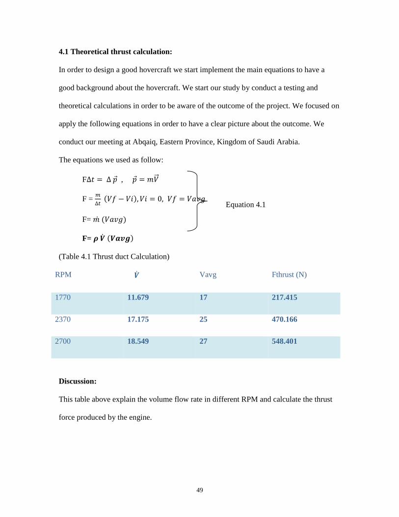
4.1 Theoretical thrust calculation:
In order to design a good hovercraft we start implement the main equations to have a
good background about the hovercraft. We start our study by conduct a testing and
theoretical calculations in order to be aware of the outcome of the project. We focused on
apply the following equations in order to have a clear picture about the outcome. We
conduct our meeting at Abqaiq, Eastern Province, Kingdom of Saudi Arabia.
The equations we used as follow:
F∆𝑡 = ∆ �⃗� , �⃗� = 𝑚�⃗⃗�
F = 𝑚
∆𝑡 (𝑉𝑓 − 𝑉𝑖), 𝑉𝑖 = 0, 𝑉𝑓 = 𝑉𝑎𝑣𝑔
F= 𝑚 ̇ (𝑉𝑎𝑣𝑔)
F= 𝝆 �̇� (𝑽𝒂𝒗𝒈)
(Table 4.1 Thrust duct Calculation)
RPM �̇� Vavg Fthrust (N)
1770 11.679 17 217.415
2370 17.175 25 470.166
2700 18.549 27 548.401
Discussion:
This table above explain the volume flow rate in different RPM and calculate the thrust
force produced by the engine.
Equation 4.1
50
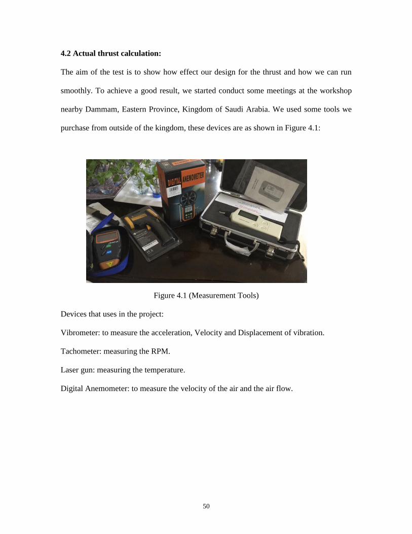
4.2 Actual thrust calculation:
The aim of the test is to show how effect our design for the thrust and how we can run
smoothly. To achieve a good result, we started conduct some meetings at the workshop
nearby Dammam, Eastern Province, Kingdom of Saudi Arabia. We used some tools we
purchase from outside of the kingdom, these devices are as shown in Figure 4.1:
Figure 4.1 (Measurement Tools)
Devices that uses in the project:
Vibrometer: to measure the acceleration, Velocity and Displacement of vibration.
Tachometer: measuring the RPM.
Laser gun: measuring the temperature.
Digital Anemometer: to measure the velocity of the air and the air flow.

51
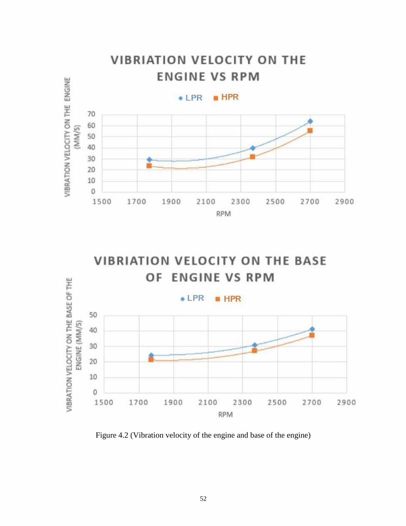
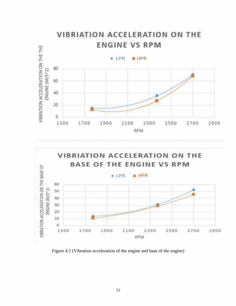
4.3 Overall Results, Analysis and Discussion:
For minimizing the vibration, we used different type of rubber depends on its properties.
In results, we found that the rubber with high pressure can consume the vibration more
than the low pressure rubber. The following charts explain the difference. Also it proves
our results.
52
Figure 4.2 (Vibration velocity of the engine and base of the engine)
53
Figure 4.3 (Vibration acceleration of the engine and base of the engine)
54
Figure 4.4 (Vibration displacement of the engine and base of the engine)
55
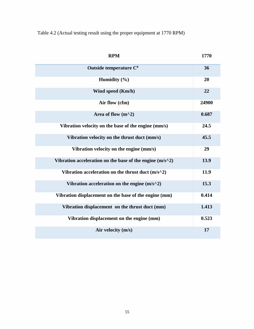
Table 4.2 (Actual testing result using the proper equipment at 1770 RPM)
RPM 1770
Outside temperature C⁰ 36
Humidity (%) 20
Wind speed (Km/h) 22
Air flow (cfm) 24900
Area of flow (m^2) 0.687
Vibration velocity on the base of the engine (mm/s) 24.5
Vibration velocity on the thrust duct (mm/s) 45.5
Vibration velocity on the engine (mm/s) 29
Vibration acceleration on the base of the engine (m/s^2) 13.9
Vibration acceleration on the thrust duct (m/s^2) 11.9
Vibration acceleration on the engine (m/s^2) 15.3
Vibration displacement on the base of the engine (mm) 0.414
Vibration displacement on the thrust duct (mm) 1.413
Vibration displacement on the engine (mm) 0.523
Air velocity (m/s) 17
56
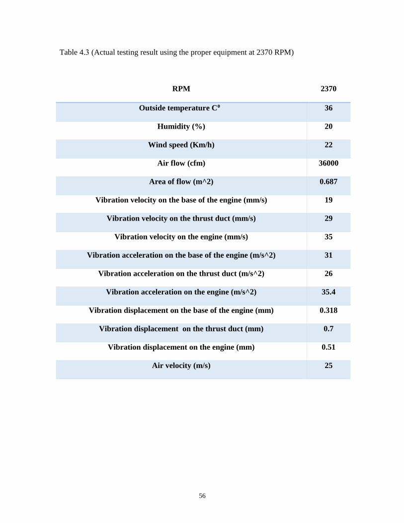
Table 4.3 (Actual testing result using the proper equipment at 2370 RPM)
RPM 2370
Outside temperature C⁰ 36
Humidity (%) 20
Wind speed (Km/h) 22
Air flow (cfm) 36000
Area of flow (m^2) 0.687
Vibration velocity on the base of the engine (mm/s) 19
Vibration velocity on the thrust duct (mm/s) 29
Vibration velocity on the engine (mm/s) 35
Vibration acceleration on the base of the engine (m/s^2) 31
Vibration acceleration on the thrust duct (m/s^2) 26
Vibration acceleration on the engine (m/s^2) 35.4
Vibration displacement on the base of the engine (mm) 0.318
Vibration displacement on the thrust duct (mm) 0.7
Vibration displacement on the engine (mm) 0.51
Air velocity (m/s) 25
57
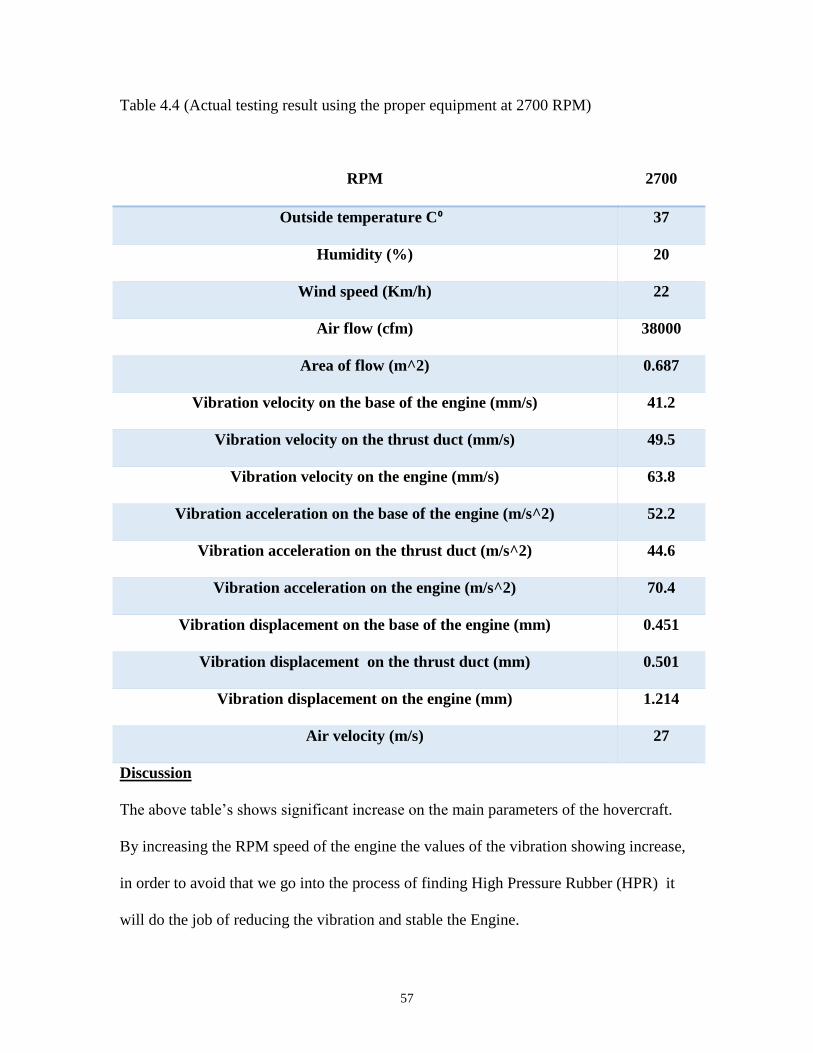
Table 4.4 (Actual testing result using the proper equipment at 2700 RPM)
RPM 2700
Outside temperature C⁰ 37
Humidity (%) 20
Wind speed (Km/h) 22
Air flow (cfm) 38000
Area of flow (m^2) 0.687
Vibration velocity on the base of the engine (mm/s) 41.2
Vibration velocity on the thrust duct (mm/s) 49.5
Vibration velocity on the engine (mm/s) 63.8
Vibration acceleration on the base of the engine (m/s^2) 52.2
Vibration acceleration on the thrust duct (m/s^2) 44.6
Vibration acceleration on the engine (m/s^2) 70.4
Vibration displacement on the base of the engine (mm) 0.451
Vibration displacement on the thrust duct (mm) 0.501
Vibration displacement on the engine (mm) 1.214
Air velocity (m/s) 27
Discussion
The above table’s shows significant increase on the main parameters of the hovercraft.
By increasing the RPM speed of the engine the values of the vibration showing increase,
in order to avoid that we go into the process of finding High Pressure Rubber (HPR) it
will do the job of reducing the vibration and stable the Engine.
58
CHAPTER 5
PROJECT MANAGMENT
5.1 PROJECT PLAN
5.2 CONTRIBUTION OF TEAM MEMBERS
5.5 PROJECT BILL OF MATERIALS AND
BUDGET
5.3 PROJECT EXECUTION MONITORING
5.4 CHALLENGES AND DECISION MAKING
59
5.1 Project Plan:
We are as one team but to be run with the time for the course. Our leader suggest to
divide the team to two groups as field work group and writing and research group. Every
group was working by all member advices. every group was exchange the ideas and
information to support other group and work as team in the same time. This management
was successful to finish the project which is not simple project for students. The team
found Mr.Fahad Hussain Al-haidar who has a work shop located in Dammam to be our
major sponsor for our project. He make the workshop to be able for the team in any time
to work and finish the project.
In table 5.1 will explain time work for each task.
(Table 5.1 Project's time frame)
Task Start Date Finish date Resources
1
Introduction
02/19/201
7
03/03/2017
Research, Books,
Journals, Hovercraft
websites,
documentaries
2
Literature Review
02/19/201
7
03/03/2017
Previous work,
journals,
undergraduating
projects
3
System Design
03/04/201
7
03/08/2017
CAD (Solidwork) ,
Hovercraft websites,
plog builders
60
4 System manufacturing and
assembly
03/09/201
7
04/13/2017
5
System Testing and Analysis
04/15/201
7
04/20/2017
Digital laser grip
thermometer, peak-
meter for wind speed
and volume of air,
digital photo laser
tachometer to measure
RPM, vibration sensor
meter, Solidwork
6 Project Management 04/20/201
7
04/27/2017 Leader of the team
7 Project Analysis 04/27/201
7
05/05/2017
8 Conclusions and Future
Recommendations
05/10/201
7
05/15/17 Depends on our
project
9
Field Work
03/25/17
End of
April
Suppliries, research
team workshop, CAD
drawing, literature
review, solidwork
calculation,

61
(Table 5.2 Work Plan)
Work Plan
Phase 1
Reviewing, researching and finding materials suppliries.
Phase 2
CAD drawing, simple calculation and choosing material.
Phase 3
Project's assembly .
Phase 4
Results and analysis.
Table 5.2 explains the work plan and the project steps. We follow these phases to manage
the work and time.
5.2 Contribution of Team Member:
All the members were effective, shared ideas, exchange ideas and opinions. Every
member try to attempt to work in all sections but because of the pressure of the Semester
and the division member to two groups we work as below table 5.2 to show exact work
for each member:

62
(Table 5.3 Task Distribution)
# Task Team member assigned
1 Researching and Writing the project report Saud Al-Shamsi,
Abdullah Al-Zahrani,
Mishal Al-Othman,
Abdullah Al-Muraisel
2 Group project allocation Abdullah Al-Muraisel
3 Gantt Chart Abdullah Al-Muraisel,
Mishal Al-Othman
4 Introduction & project objective (report) Mishal Al-Othman
5 Literature review (report) Saud Al-Shamsi
6 System Design (report) Abdullah Al-Zhrani,
Abdullah Al-Muraisel,
Mishal Al-Othman, Saud
Al-Shamsi
7 Project Management Saud Al-Shamsi,
Abdullah Al-Muraisel
8 Project analysis , Mishal Al-Othman
9 Meet Dr.ROODI biweekly All members
10 CAD-drawing Abdullah Al-Muraisel,
Mahdi Al-Marzoug,
Mishal Al-Othman
11 Design and build engine base Abdullah Al-Muraisl,
63
Hussain Al-Haidr, Mahdi
Al-Marzoug
12 Design and build lift thrust divider system Abdullah Al-Muraisl,
Hussain Al-Haidr, Mahdi
Al-Marzoug
13 Choosing material Abdullah Al-Muraisel
14 Applying and choosing fan system Abdullah Al-Muraisel
15 Manufacturing Hovercraft Base Abdullah Al-Muraisel,
Hussain Al-Haidr, Mahdi
Al-Marzoug
16 Manufacturing Thrust Duct Abdullah Al-Muraisl,
Hussain Al-Haidr, Mahdi
Al-Marzoug
17 Choosing and applying the engine Abdullah Al-Muraisel
18 Measurement and Testing Abdullah Al-Muraisel,
Mahdi Al-Marzoug, Saud
Al-Shamsi,
Hussain Al-Haidr
19 Applying the air fan to the shaft of the engine Abdullah Al-Muraisl,
Hussain Al-Haidr, Mahdi
Al-Marzoug, Saud Al-
Shamsi

64
20 Manufacturing Rudders Abdullah Al-Muraisl,
Hussain Al-Haidr, Mahdi
Al-Marzoug
21 Applying the skirt around the hovercraft Abdullah Al-Muraisl,
Hussain Al-Haidr, Mahdi
Al-Marzoug
22 Applying fiberglass coating Abdullah Al-Muraisl,
Hussain Al-Haidr, Mahdi
Al-Marzoug
The above table 5.3 explains all the tasks and every member that work on the task.
5.3 Project Execution Monitoring:
The team meet twice every week to discuss the updated progress. The leader for
management the meeting is Mr. Abdullah Al-Zahrani. He is an employee and night
student and other members goes with his available time. All meeting was to review the
previous work and planning for next part. All meetings was a helpful for each member
because every member try to exchange his own idea with others. Field group and writing
group were try to work smoothly together not just focusing on their part. Every group
support the other. When we face any problem, we try our best solution to ask our advisor
about it. The advisor was successful to help us to work as engineers and find the solution
by ourselves.
65
5.4 Challenges and Decision Making:
The group were suffering with the time of the meeting. One of the members is an
employee and he faced many problems to manage his time between his work, classes, and
project meetings. The leader tried hard to manage the meeting to be at noon to be flexible
for all members. On the other hand, there is another member living outside of our
meetings. Also, this member faced a hard situations. We solve this problem to make
some of the meetings by an application that is meet all of us together online. Our group
did not faced any cooperating problems. The members were divided the work and made
the plan early which is in the beginning of the semester. Every member was supporting
the other in any needs that happened for the project.
The main problem was the availability of workshop. It takes too much time to find a
place that we can make our field work. After spending too much time, Mr.Fahad Al-
Haidar heard about our project which he is father for one of the members. He contacts
with the leader to ask about all needs for the project and he tell the leader that some
equipments that the group need it is available in his workshop. Also the materials and
components that the group looking for is not that much easy to find it. Some of the
members were looking for the materials and components, others were try to chose the
materials by reading and researching to give the correct choosing.
We used a material to manufacture the thrust duct which was not the material that going
with our project. The material was too soft and after finishing the thrust by this material,
we see that is not stable because it is a thick material. It does not give us a unique circle
that can handle a fiber glass coating. Another problem is when we try to make a hole in
the fan for the nails. It was too difficult to make it uniform holes and we were scared
66
from any damaging might happened for the fan. During the wilding work for the thrust,
we burn a small area from the wood base. This happened because, we do not have that
much skills for wilding work.
5.5 Project Bill of Materials and Budget:
(Table 5.4 Project Budget)
Cost Analysis Sponsor Group Payment Cost (SR)
Horizontal Shaft Engine 600 2200 2800
Design and Build Engine
Base
200 - 200
Design and Manufacture
Lift Thrust Divider System
200 - 200
Plywood 150 - 150
4 Polystyrene Foam Sheets - 60 15 each = 60
Thrust Duct 600 - 600
Fan - 1300 1300
Skirt - 150 150
Rudders and Control System 250 - 250
Fiber Glass Coating 1000 1150 2150
Fabrication ✓ - -
Total 3000 4860 7860 SR
As a team with this big project we found a sponsor for our project. The above table 5.4
shows the total payment of the sponsor and the members.
67
CHAPTER 6
PROJECT ANALYSIS
6.1 LIFE-LONG LEARNING
6.2 IMPACT OF ENGINEERING SOLUTION
6.3 CONTEMPORART ISSUES ADDRESSED
68
6.1 Life-long Learning:
This experience we had as a team during this project helped us to compute our skills and
knowledge gained through our undergrad study. It shows how we can work as teams and
how we solve any difficulty we might face. What makes our implementation of the
competencies special is that we had a project required a lot of teamwork, leadership, and
technical communication skills a lot compare with other projects. Time and cost
management also plays a significant factor as well, because this type of project required a
lot of testing, calculation and required to figure out the necessary equipment with high
quality and ensure its functionality and efficiency within the cost. With all that, we as the
team successfully done this iconic project within the time and cost limitations. Also in
this project, we went to some journals and other expertise on the web that related to this
type of project, and we get to know some ideas and ways on manufacturing. One great
example of this is the rudder; many kinds and mechanisms could be implemented plus the
engine type we figure out that there are many kinds of drivers in the market we can
control the speed and RPM, but others run fixed by the manufacturer. Furthermore, we
had a chance to look into some similar project been done in other university students
worldwide and try to make some difference in material selection and to design as well.
When it comes to calculation, we started doing it by using SolidWorks program to
achieve the necessary calculation in the professional and iconic way.
6.2 Impact of Engineering Solutions:
When it come to the impacts that our project achieve, we can divide this achievement into
three categories: society, environment, and economy we will talk in details.
69
6.2.1 Society:
Hovercraft consider one of the efficient ways of transportation. It easy to handle and
control besides that, it easy to maintained and don’t require too much work to fix.
Hovercraft plays a significant role in rescue people in a harsh situation like what
happened in the eastern province of the Kingdom on 16th of February 2017 the civil
defense uses it in reaching the area gets blocked due to flooded roads and tunnels.
Additional uses of the hovercraft in situations like wars. Armies worldwide use it to
transport their equipment and armed forces. Also, it could be utilized by the marine
people to guide and towing heavy ships to the shore and vice versa.
6.2.2 Environment:
We can consider the hovercraft environment-friendly comparing with other vehicles used
in many situations nowadays. When it comes to the advantages, the less friction between
the hovercraft lead to less fuel burnt to move, and less friction on the surface means less
disturbance to the environment. According to “Hovercraft technology: Economics and
Application 1989 by J.R. Amyot” the hovercraft has to very low pressure “footprint” and
he mentions that average human exerts pressure on the ground is around 25Ibs.per square
inch when walking. Comparing with hovercraft that exerts a pressure of 1/3Ib.per square
inch regardless of its speed. With all that we can see that the hovercraft are saving the
green land and reduce the assumption of destroying it.
6.2.3 Economy:
Saudi Arabia and GCC countries consider one of the biggest countries worldwide in
depending on oil and gas. Moreover, by removing the subsidization from the oil and gas
products steadily offering oil to your V8 car will be much difficult. By using the

70
hovercraft for the nearby areas instead of your V8 car, it will make a big difference, and
it will save your budget at the end.
6.3 Contemporary Issues Addressed:
Before start talk about the issues that are facing our GCC countries and Saudi Arabia, we
will describe some of the difficulties we faced during this project. It starts by leaking for
sources and information between the student and the real world outside the campus.
There is no good infrastructure, in other words; we spend a couple of days just looking
for any company or workshop just to manufacture our parts and assemble them together.
Also, we suffered a lot because there is some part you cannot manufacture in the
kingdom and we do not have any solution except ordering it from outside. When it come
to the GCC countries and Saudi Arabia, there are some real steps taken to accomplish
self-sustainability in areas regarding manufacturing and development. Moreover, with
Saudi Arabia’s vision 2030 there are going to be big and significant change many aspects
and support of youth from the beginning of their academic career until they become very
professionals and supporting the developing of our country.
71
CHAPTER 7
CONCLUSIONS AND FUTURE
RECOMMENDATION
7.1 COCLUSIONS
7.2 FUTURE RECOMMANADATIONS

72
7.1 Conclusions
In consolation, we as a team went into the process of designing and manufacturing of one
person hovercraft. Hovercraft is a vehicle which can float in any lands also it is known by
Air Cushion Vehicle due to its ability to move by cushion or skirt filled with air. The
concept of the hovercraft is simple, starts with a particular kind of wood that has the
property in carrying loads attached to a skirt in order to surround the air which leads to
developing pressure under the hovercraft. The ducting system or “thrust duct” we used a
thin sheet of steel to create the thrust probably. When it comes to the power system, it
runs with a motor connected with the propeller made of wood which generates the thrust
required for both thrust and lifts. Also, we went into the process of designing the rudder
system which used in steer and directs the thrust air generated by the motor in the
required direction. After manufacturing parts has been done, we start measuring the
vibration, temperature, generated air and distance travelled by the vehicle.
During this period we spend on this project, we get to know a lot of things that are
essential and required to accomplish a successful project. It starts with time management,
time plays a big role in this project. Due to the lack of places that supply the required
materials for duct and the base, we manage the time between team members to avoid any
losing of time and finish the work within the time. Also we get to know how to assemble
multiple part together. It was very difficult process but we did it and preformed the
required checks to insure that fit within the standards of the hovercraft. We learned about
vibration and how we can minimize it on the hovercraft. Besides that, we get to know the
importance of minimizing the weight which is a major part in any design of vehicles.

73
7.2 Future Recommendations
As a team, we come up with recommendations that lead to have a faster and more durable
hovercraft which give better results.
1- Try to reduce vibration generated by the motor by using some materials to absorb
the vibration impacts.
2- For fast hovercraft, we recommend to use two engines, one horizontal shaft for
thrust and one vertical shaft for the lift to increase the power which leads to more
powerful hovercraft which can handle more weight and sliding easily on surfaces.
3- Use Carbon-Fibre or Fiberglas for all body of the hovercraft to minimize the total
weight but it is costly.

74
REFERENECES:
1- Rothwell, R., & Gardiner, P. (1985). Invention, innovation, re-innovation and the role of
the user: a case study of British hovercraft development. Technovation, 3(3), 167-186.
2- Crewe, P. R., & Eggington, W. J. (1960). The hovercraft—a new concept in maritime
transport. Trans. R. Inst. Naval Arch, 102, 315-356.
3- Rothwell, R. (1986). Innovation and re‐ innovation: A role for the user. Journal of
Marketing Management, 2(2), 109-123.
4- Cross, I., & O'Flaherty, C. A. (1975). Introduction to hovercraft and hoverports. Pitman.
5- Coates, C. W. (2005, January). Extracting engineering principles from a hovercraft design
project for engineering sophomores. In ASME 2005 International Mechanical Engineering
Congress and Exposition (pp. 381-386). American Society of Mechanical Engineers.
6- Amyot, J. R. (Ed.). (2013). Hovercraft technology, economics and applications (Vol. 11).
Elsevier.
7- Richards, E. J., & Sharland, I. J. (1965). Hovercraft noise and its suppression. Journal of
the Royal Aeronautical Society, 69(654), 387-398.
8- Wilson, J. (2004). :: DiscoverHover :: News Coverage - The Build-a-Hovercraft School
Project ::. [online] Discoverhover.org.

75
APPENDIX - A
PROGRESS REPORTS
# REPORT 1
# REPORT 2
# REPORT 3
# REPORT 4

76
SDP – WEEKLY MEETING REPORT
Department of Electrical Engineering
Prince Mohammad bin Fahd University
SEMESTER: Spring Semester
ACADEMIC
YEAR:
2016-2017
PROJECT
TITLE
One Person Hovercraft
SUPERVISOR
S
Dr. Faramarz Djavanrood & Dr. Nader Sawalhi
Month 1: February
ID Number Member Name
201100546 Abdullah Al-Muraisel
201302079 Meshal Othman
201000170 Abdullah AlZahrani
201300297 Hussain ALHaider
201201060 Mahdi ALmarzoug
201100333 Saud Al-Shamsi
77
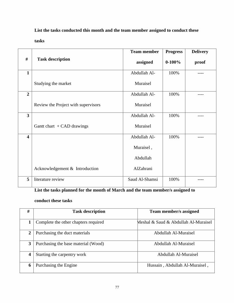
List the tasks conducted this month and the team member assigned to conduct these
tasks
# Task description
Team member
assigned
Progress
0-100%
Delivery
proof
1
Studying the market
Abdullah Al-
Muraisel
100% ----
2
Review the Project with supervisors
Abdullah Al-
Muraisel
100% ----
3
Gantt chart + CAD drawings
Abdullah Al-
Muraisel
100% ----
4
Acknowledgement & Introduction
Abdullah Al-
Muraisel ,
Abdullah
AlZahrani
100% ----
5 literature review Saud Al-Shamsi 100% ----
List the tasks planned for the month of March and the team member/s assigned to
conduct these tasks
# Task description Team member/s assigned
1 Complete the other chapters required Meshal & Saud & Abdullah Al-Muraisel
2 Purchasing the duct materials Abdullah Al-Muraisel
3 Purchasing the base material (Wood) Abdullah Al-Muraisel
4 Starting the carpentry work Abdullah Al-Muraisel
6 Purchasing the Engine Hussain , Abdullah Al-Muraisel ,

78
7 Order the Propeller From USA Abdullah Al-Muraisel
8 fabrication of control system (rudders) Mahdi
- To be Filled by Project Supervisor and team leader:
- Please have your supervisor fill according to the criteria shown below
Outcome f:
An understanding of professional and ethical responsibility.
Criteria None (1) Low (2) Moderate (3) High (4)
f1. Demonstrate
an
understanding
of engineering
professional and
ethical
standards in
dealing with
public safety
and interest
Fails to
Demonstrate an
understanding
of engineering
professional and
ethical
standards in
dealing with
public safety
and interest
Shows limited
and less than
adequate
understanding of
engineering
professional and
ethical standards
in dealing with
public safety
and interest
Demonstrates
satisfactory
an
understandin
g of
engineering
professional
and ethical
standards in
dealing with
public safety
and interest
Understands
appropriately and
accurately the
engineering professional
and ethical standards in
dealing with public safety
and interest
Outcome d:
An ability to function on multidisciplinary teams.
Criteria None (1) Low (2) Moderate (3) High (4)

79
d1. Ability to
develop team
work plans and
allocate
resources and
tasks
Fails to develop
team work plans
and allocate
resources and
tasks
Shows limited
and less than
adequate ability to
develop team
work plans and
allocate resources
and tasks
Demonstrates
satisfactory
ability to
develop team
work plans and
allocate
resources and
tasks
Understands and
applies proper and
accurate team work
plans and allocate
resources and tasks
d2. Ability to
participate and
function
effectively in
team work
projects
Fails to
participate and
function
effectively in
team work
projects
Shows limited
and less than
adequate ability to
participate and
function
effectively in
team work
projects
Demonstrates
satisfactory
ability to
participate and
function
effectively in
team work
projects
Understands and
participates
properly and
function effectively
in team work
projects
d3. Ability to
communicate
effectively with
team members
Fails to
communicate
effectively with
team members
Shows limited
and less than
adequate ability to
communicate
effectively with
team members
Demonstrates
satisfactory
ability to
communicate
effectively with
team members
3. Understands
and communicates
properly and
effectively with
team members
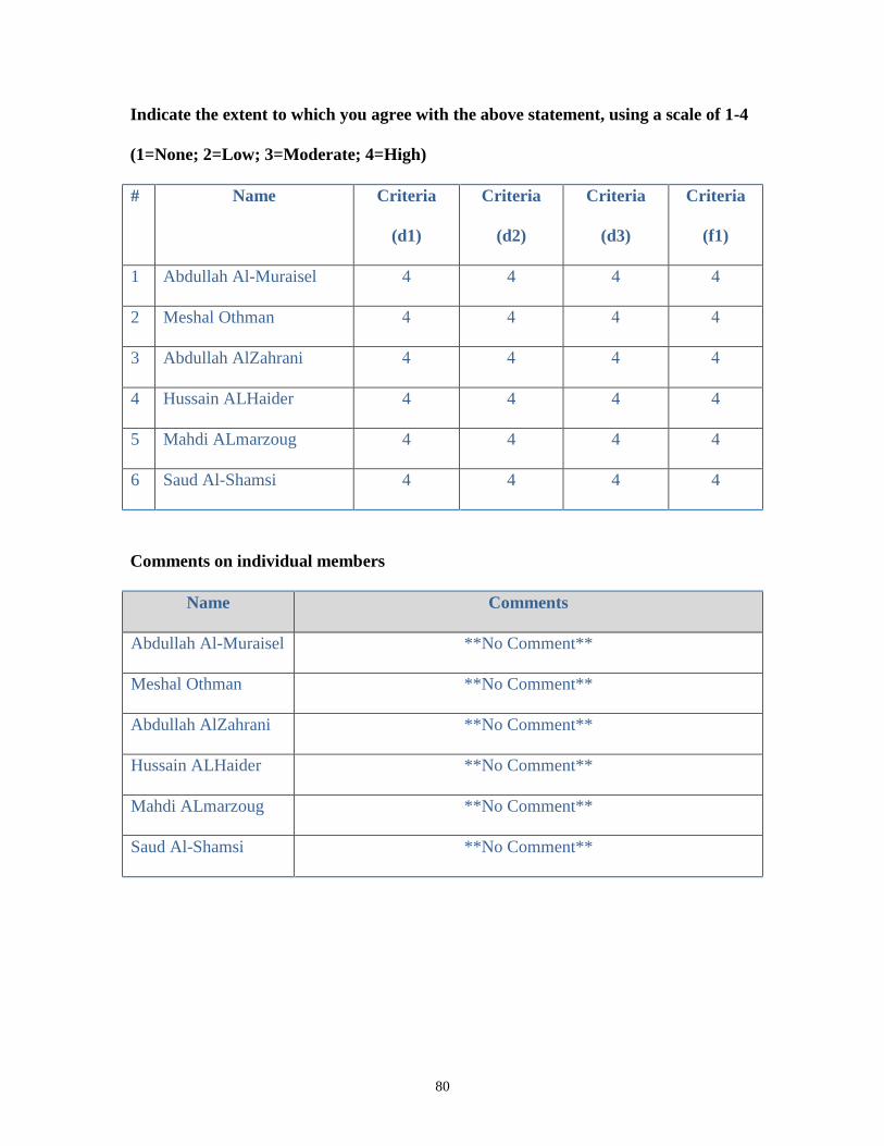
80
Indicate the extent to which you agree with the above statement, using a scale of 1-4
(1=None; 2=Low; 3=Moderate; 4=High)
# Name Criteria
(d1)
Criteria
(d2)
Criteria
(d3)
Criteria
(f1)
1 Abdullah Al-Muraisel 4 4 4 4
2 Meshal Othman 4 4 4 4
3 Abdullah AlZahrani 4 4 4 4
4 Hussain ALHaider 4 4 4 4
5 Mahdi ALmarzoug 4 4 4 4
6 Saud Al-Shamsi 4 4 4 4
Comments on individual members
Name Comments
Abdullah Al-Muraisel **No Comment**
Meshal Othman **No Comment**
Abdullah AlZahrani **No Comment**
Hussain ALHaider **No Comment**
Mahdi ALmarzoug **No Comment**
Saud Al-Shamsi **No Comment**

81
SDP – WEEKLY MEETING REPORT
Department of Electrical Engineering
Prince Mohammad bin Fahd University
SEMESTER: Spring Semester
ACADEMIC
YEAR:
2016-2017
PROJECT
TITLE
One Person Hovercraft
SUPERVISOR
S
Dr. Faramarz Djavanrood & Dr. Nader Sawalhi
Month 2: March
ID Number Member Name
201100546 Abdullah Al-Muraisel
201302079 Meshal Othman
201000170 Abdullah AlZahrani
201300297 Hussain ALHaider
201201060 Mahdi ALmarzoug
201100333 Saud Al-Shamsi

82
List the tasks conducted this month and the team member assigned to conduct these
tasks
# Task description
Team member
assigned
Progres
s
0-100%
Delivery proof
1
Report chapters 3 &4
Meshal&Saud&
Abdullah AlZahrani
100% Report Attached
2 Purchasing the duct materials + base material
(Wood) + Order the Propeller From USA
Abdullah Al-Muraisel
&Mahdi&Hussain
100% Photo Attached
3 Purchasing the Engine Hussain 100% ----
4 Purchasing the safety equipments Mahdi 100% Photo Attached
5 Discussion meeting before the assembly
work
All Members 100% Photo Attached
List the tasks planned for the month of April and the team member/s assigned to
conduct these tasks
# Task description Team member/s assigned
1 Starting the carpentry work (shifted from march) All Members
2 Figure out a place starts the assembly Hussain
3 Ordering the measurement equipment from USA Abdullah Al-Muraisel
4 Find the wilding and machining shops Hussain & Mahdi
6 Finding sponsors for the project Hussain

83
- To be Filled by Project Supervisor and team leader:
- Please have your supervisor fill according to the criteria shown below
Outcome f:
An understanding of professional and ethical responsibility.
Criteria None (1) Low (2) Moderate (3) High (4)
f1. Demonstrate
an
understanding
of engineering
professional and
ethical
standards in
dealing with
public safety
and interest
Fails to
Demonstrate an
understanding
of engineering
professional and
ethical
standards in
dealing with
public safety
and interest
Shows limited
and less than
adequate
understanding of
engineering
professional and
ethical standards
in dealing with
public safety
and interest
Demonstrates
satisfactory
an
understandin
g of
engineering
professional
and ethical
standards in
dealing with
public safety
and interest
Understands
appropriately and
accurately the
engineering professional
and ethical standards in
dealing with public safety
and interest
Outcome d:
An ability to function on multidisciplinary teams.
Criteria None (1) Low (2) Moderate (3) High (4)
d1. Ability to
develop team
work plans and
Fails to develop
team work plans
and allocate
Shows limited
and less than
adequate ability to
Demonstrates
satisfactory
ability to
Understands and
applies proper and
accurate team work

84
allocate
resources and
tasks
resources and
tasks
develop team
work plans and
allocate resources
and tasks
develop team
work plans and
allocate
resources and
tasks
plans and allocate
resources and tasks
d2. Ability to
participate and
function
effectively in
team work
projects
Fails to
participate and
function
effectively in
team work
projects
Shows limited
and less than
adequate ability to
participate and
function
effectively in
team work
projects
Demonstrates
satisfactory
ability to
participate and
function
effectively in
team work
projects
Understands and
participates
properly and
function effectively
in team work
projects
d3. Ability to
communicate
effectively with
team members
Fails to
communicate
effectively with
team members
Shows limited
and less than
adequate ability to
communicate
effectively with
team members
Demonstrates
satisfactory
ability to
communicate
effectively with
team members
3. Understands
and communicates
properly and
effectively with
team members
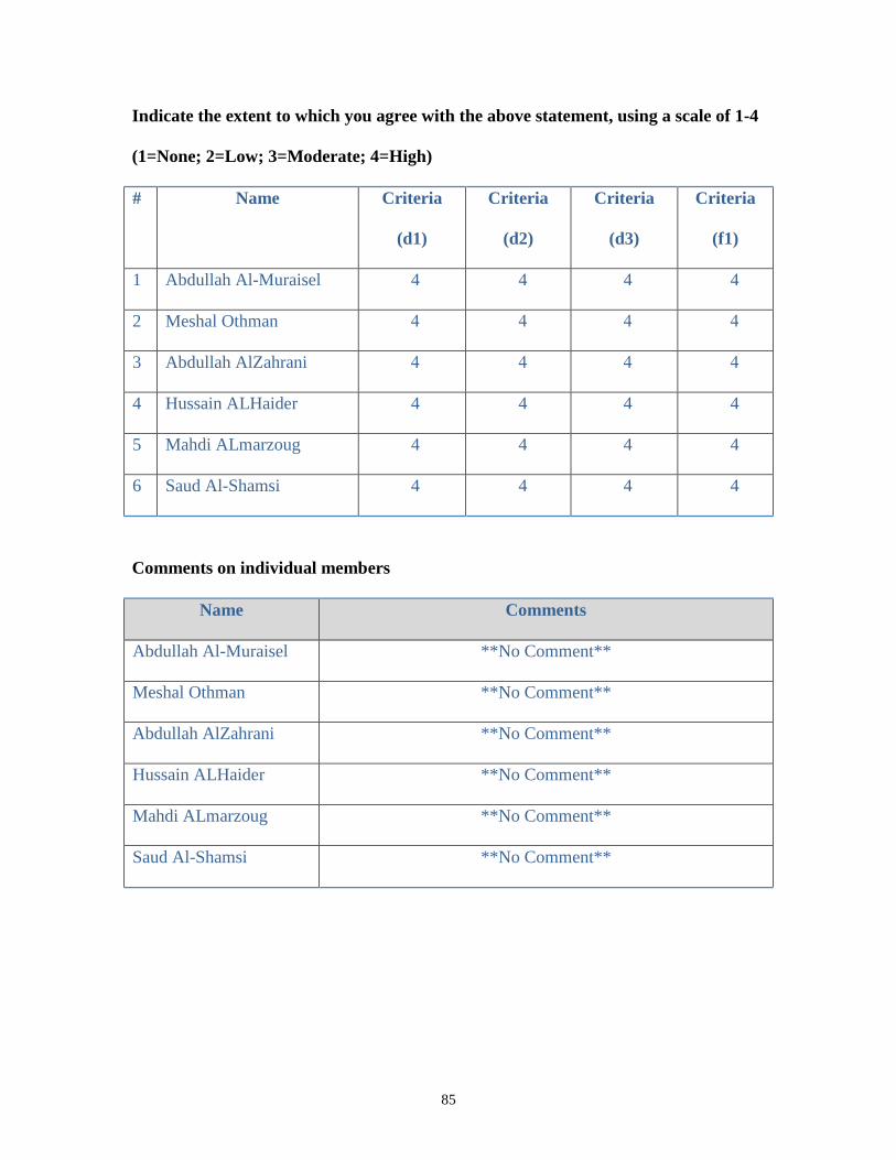
85
Indicate the extent to which you agree with the above statement, using a scale of 1-4
(1=None; 2=Low; 3=Moderate; 4=High)
# Name Criteria
(d1)
Criteria
(d2)
Criteria
(d3)
Criteria
(f1)
1 Abdullah Al-Muraisel 4 4 4 4
2 Meshal Othman 4 4 4 4
3 Abdullah AlZahrani 4 4 4 4
4 Hussain ALHaider 4 4 4 4
5 Mahdi ALmarzoug 4 4 4 4
6 Saud Al-Shamsi 4 4 4 4
Comments on individual members
Name Comments
Abdullah Al-Muraisel **No Comment**
Meshal Othman **No Comment**
Abdullah AlZahrani **No Comment**
Hussain ALHaider **No Comment**
Mahdi ALmarzoug **No Comment**
Saud Al-Shamsi **No Comment**
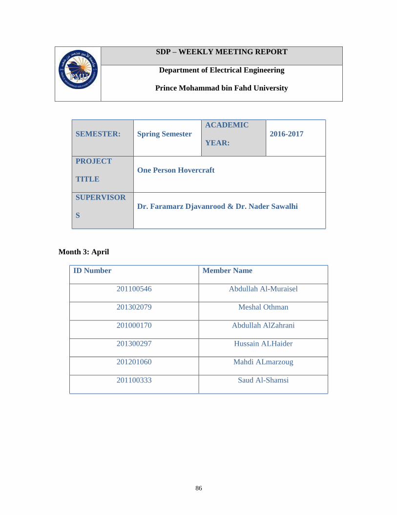
86
SDP – WEEKLY MEETING REPORT
Department of Electrical Engineering
Prince Mohammad bin Fahd University
SEMESTER: Spring Semester
ACADEMIC
YEAR:
2016-2017
PROJECT
TITLE
One Person Hovercraft
SUPERVISOR
S
Dr. Faramarz Djavanrood & Dr. Nader Sawalhi
Month 3: April
ID Number Member Name
201100546 Abdullah Al-Muraisel
201302079 Meshal Othman
201000170 Abdullah AlZahrani
201300297 Hussain ALHaider
201201060 Mahdi ALmarzoug
201100333 Saud Al-Shamsi
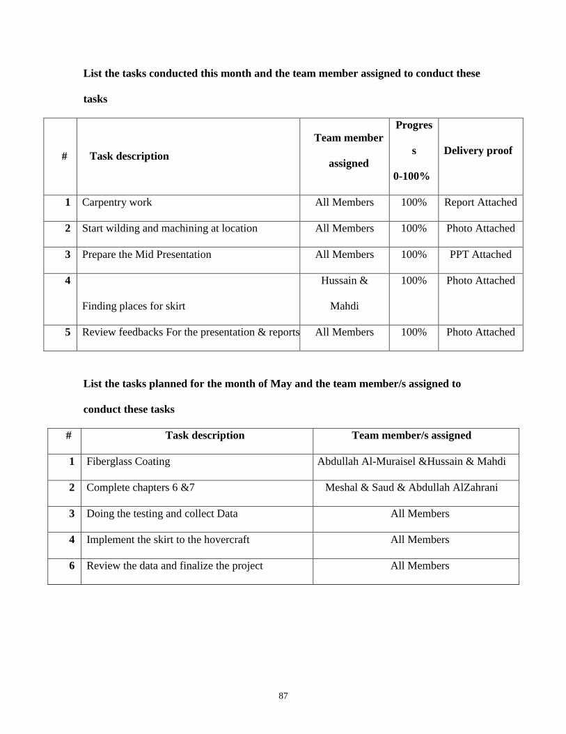
87
List the tasks conducted this month and the team member assigned to conduct these
tasks
# Task description
Team member
assigned
Progres
s
0-100%
Delivery proof
1 Carpentry work All Members 100% Report Attached
2 Start wilding and machining at location All Members 100% Photo Attached
3 Prepare the Mid Presentation All Members 100% PPT Attached
4
Finding places for skirt
Hussain &
Mahdi
100% Photo Attached
5 Review feedbacks For the presentation & reports All Members 100% Photo Attached
List the tasks planned for the month of May and the team member/s assigned to
conduct these tasks
# Task description Team member/s assigned
1 Fiberglass Coating Abdullah Al-Muraisel &Hussain & Mahdi
2 Complete chapters 6 &7 Meshal & Saud & Abdullah AlZahrani
3 Doing the testing and collect Data All Members
4 Implement the skirt to the hovercraft All Members
6 Review the data and finalize the project All Members

88
- To be Filled by Project Supervisor and team leader:
- Please have your supervisor fill according to the criteria shown below
Outcome f:
An understanding of professional and ethical responsibility.
Criteria None (1) Low (2) Moderate (3) High (4)
f1. Demonstrate
an
understanding
of engineering
professional and
ethical
standards in
dealing with
public safety
and interest
Fails to
Demonstrate an
understanding
of engineering
professional and
ethical
standards in
dealing with
public safety
and interest
Shows limited
and less than
adequate
understanding of
engineering
professional and
ethical standards
in dealing with
public safety
and interest
Demonstrates
satisfactory
an
understandin
g of
engineering
professional
and ethical
standards in
dealing with
public safety
and interest
Understands
appropriately and
accurately the
engineering professional
and ethical standards in
dealing with public safety
and interest
Outcome d:
An ability to function on multidisciplinary teams.
Criteria None (1) Low (2) Moderate (3) High (4)
d1. Ability to
develop team
work plans and
Fails to develop
team work plans
and allocate
Shows limited
and less than
adequate ability to
Demonstrates
satisfactory
ability to
Understands and
applies proper and
accurate team work
89
allocate
resources and
tasks
resources and
tasks
develop team
work plans and
allocate resources
and tasks
develop team
work plans and
allocate
resources and
tasks
plans and allocate
resources and tasks
d2. Ability to
participate and
function
effectively in
team work
projects
Fails to
participate and
function
effectively in
team work
projects
Shows limited
and less than
adequate ability to
participate and
function
effectively in
team work
projects
Demonstrates
satisfactory
ability to
participate and
function
effectively in
team work
projects
Understands and
participates
properly and
function effectively
in team work
projects
d3. Ability to
communicate
effectively with
team members
Fails to
communicate
effectively with
team members
Shows limited
and less than
adequate ability to
communicate
effectively with
team members
Demonstrates
satisfactory
ability to
communicate
effectively with
team members
3. Understands
and communicates
properly and
effectively with
team members
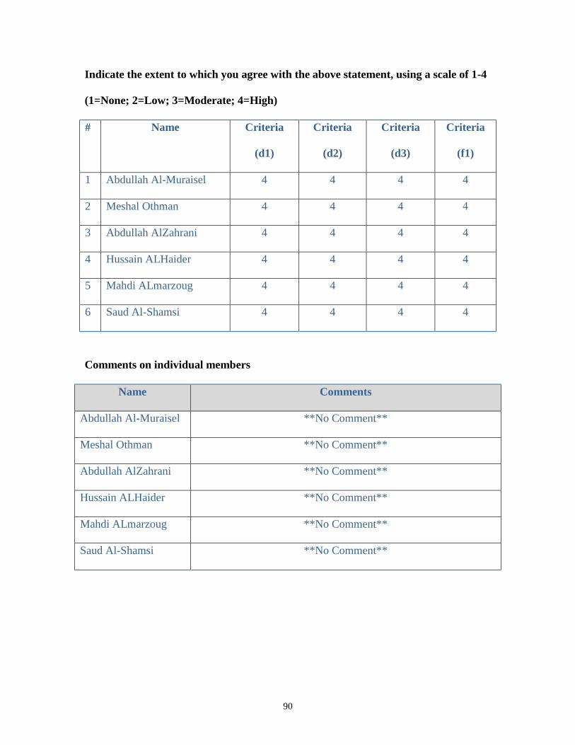
90
Indicate the extent to which you agree with the above statement, using a scale of 1-4
(1=None; 2=Low; 3=Moderate; 4=High)
# Name Criteria
(d1)
Criteria
(d2)
Criteria
(d3)
Criteria
(f1)
1 Abdullah Al-Muraisel 4 4 4 4
2 Meshal Othman 4 4 4 4
3 Abdullah AlZahrani 4 4 4 4
4 Hussain ALHaider 4 4 4 4
5 Mahdi ALmarzoug 4 4 4 4
6 Saud Al-Shamsi 4 4 4 4
Comments on individual members
Name Comments
Abdullah Al-Muraisel **No Comment**
Meshal Othman **No Comment**
Abdullah AlZahrani **No Comment**
Hussain ALHaider **No Comment**
Mahdi ALmarzoug **No Comment**
Saud Al-Shamsi **No Comment**

91
SDP – WEEKLY MEETING REPORT
Department of Electrical Engineering
Prince Mohammad bin Fahd University
SEMESTER: Spring Semester
ACADEMIC
YEAR:
2016-2017
PROJECT
TITLE
One Person Hovercraft
SUPERVISOR
S
Dr. Faramarz Djavanrood & Dr. Nader Sawalhi
Month 4: May
ID Number Member Name
201100546 Abdullah Al-Muraisel
201302079 Meshal Othman
201000170 Abdullah AlZahrani
201300297 Hussain ALHaider
201201060 Mahdi ALmarzoug
201100333 Saud Al-Shamsi
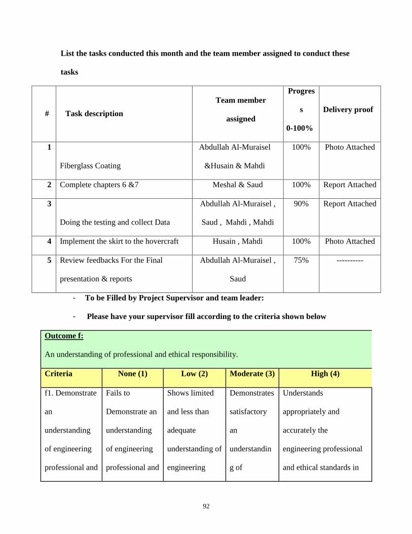
92
List the tasks conducted this month and the team member assigned to conduct these
tasks
# Task description
Team member
assigned
Progres
s
0-100%
Delivery proof
1
Fiberglass Coating
Abdullah Al-Muraisel
&Husain & Mahdi
100% Photo Attached
2 Complete chapters 6 &7 Meshal & Saud 100% Report Attached
3
Doing the testing and collect Data
Abdullah Al-Muraisel ,
Saud , Mahdi , Mahdi
90% Report Attached
4 Implement the skirt to the hovercraft Husain , Mahdi 100% Photo Attached
5 Review feedbacks For the Final
presentation & reports
Abdullah Al-Muraisel ,
Saud
75% ----------
- To be Filled by Project Supervisor and team leader:
- Please have your supervisor fill according to the criteria shown below
Outcome f:
An understanding of professional and ethical responsibility.
Criteria None (1) Low (2) Moderate (3) High (4)
f1. Demonstrate
an
understanding
of engineering
professional and
Fails to
Demonstrate an
understanding
of engineering
professional and
Shows limited
and less than
adequate
understanding of
engineering
Demonstrates
satisfactory
an
understandin
g of
Understands
appropriately and
accurately the
engineering professional
and ethical standards in

93
ethical
standards in
dealing with
public safety
and interest
ethical
standards in
dealing with
public safety
and interest
professional and
ethical standards
in dealing with
public safety
and interest
engineering
professional
and ethical
standards in
dealing with
public safety
and interest
dealing with public safety
and interest
Outcome d:
An ability to function on multidisciplinary teams.
Criteria None (1) Low (2) Moderate (3) High (4)
d1. Ability to
develop team
work plans and
allocate
resources and
tasks
Fails to develop
team work plans
and allocate
resources and
tasks
Shows limited
and less than
adequate ability to
develop team
work plans and
allocate resources
and tasks
Demonstrates
satisfactory
ability to
develop team
work plans and
allocate
resources and
tasks
Understands and
applies proper and
accurate team work
plans and allocate
resources and tasks
d2. Ability to
participate and
function
effectively in
team work
Fails to
participate and
function
effectively in
team work
Shows limited
and less than
adequate ability to
participate and
function
Demonstrates
satisfactory
ability to
participate and
function
Understands and
participates
properly and
function effectively
in team work

94
projects projects effectively in
team work
projects
effectively in
team work
projects
projects
d3. Ability to
communicate
effectively with
team members
Fails to
communicate
effectively with
team members
Shows limited
and less than
adequate ability to
communicate
effectively with
team members
Demonstrates
satisfactory
ability to
communicate
effectively with
team members
3. Understands
and communicates
properly and
effectively with
team members
Indicate the extent to which you agree with the above statement, using a scale of 1-4
(1=None; 2=Low; 3=Moderate; 4=High)
# Name Criteria
(d1)
Criteria
(d2)
Criteria
(d3)
Criteria
(f1)
1 Abdullah Al-Muraisel 4 4 4 4
2 Meshal Othman 4 4 4 4
3 Abdullah AlZahrani 4 4 4 4
4 Hussain ALHaider 4 4 4 4
5 Mahdi ALmarzoug 4 4 4 4
6 Saud Al-Shamsi 4 4 4 4
95
Comments on individual members
Name Comments
Abdullah Al-
Muraisel
**No Comment**
Meshal Othman **No Comment**
Abdullah AlZahrani **No Comment**
Hussain ALHaider **No Comment**
Mahdi ALmarzoug **No Comment**
Saud Al-Shamsi **No Comment**

96
APPENDIX - B
BILL OF MATERIALS

97

98

99

100

101

102

103

104

105

106

107

108

109

110

111

112

113

114

115

116
APPENDIX - E
OPERATIOB MANUEL
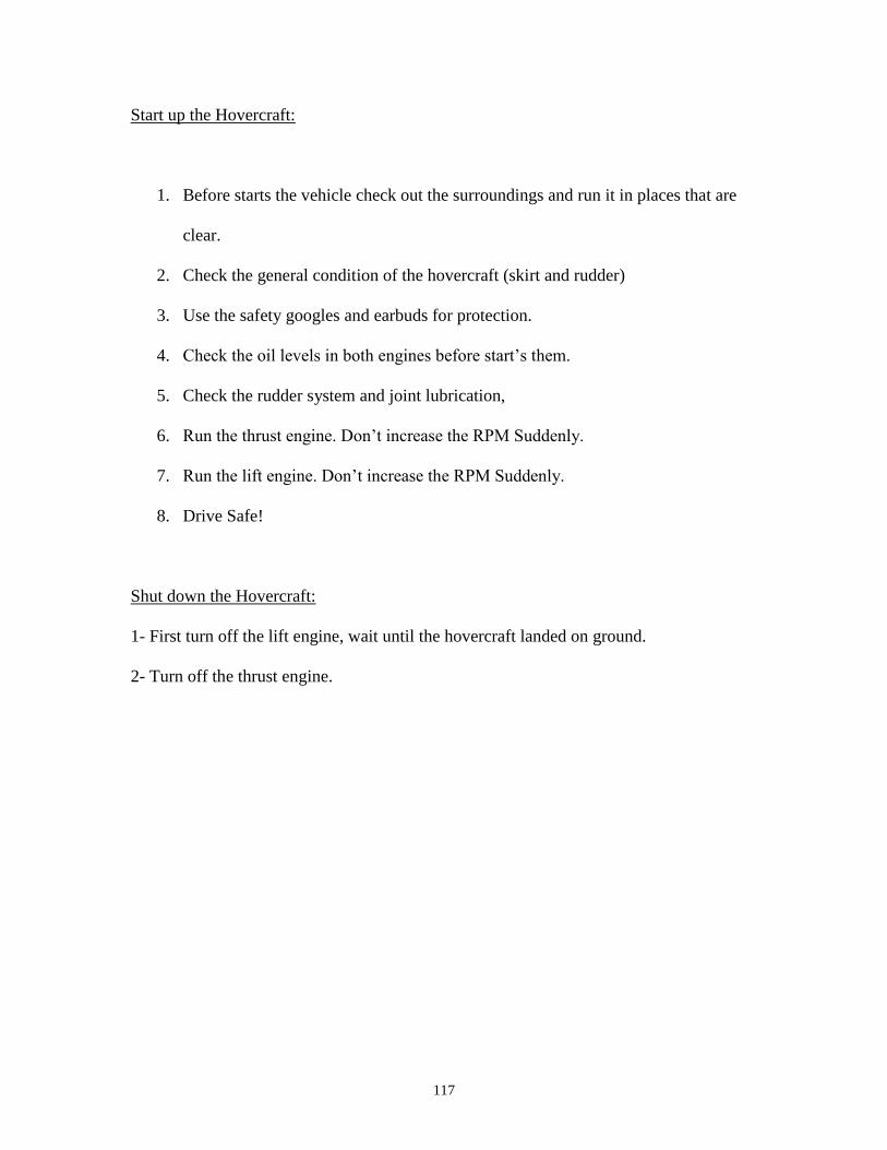
117
Start up the Hovercraft:
1. Before starts the vehicle check out the surroundings and run it in places that are
clear.
2. Check the general condition of the hovercraft (skirt and rudder)
3. Use the safety googles and earbuds for protection.
4. Check the oil levels in both engines before start’s them.
5. Check the rudder system and joint lubrication,
6. Run the thrust engine. Don’t increase the RPM Suddenly.
7. Run the lift engine. Don’t increase the RPM Suddenly.
8. Drive Safe!
Shut down the Hovercraft:
1- First turn off the lift engine, wait until the hovercraft landed on ground.
2- Turn off the thrust engine.