Embed Size (px)
DESCRIPTION
Physical Hovercraft Design
Citation preview
Project Phase 2Physical Hovercraft Design
MechatronicsSENG 466
University of Victoria
Mat Conyers V00485210Aurora Walker V00136694
Bob Warwick V00693431
Page 1
Table of ContentsTable of Figures 4
Introduction 5
1.1 Abstract 5
1.2 Requirement Specification 5
2. Prototype Designs 6
2.1 Auroracraft 7
2.1.1 Concept 7
2.1.2 Prototype 8
2.1.3 Testing 9
2.1.4 Impact on Project 10
2.2 The Bobocraft 11
2.2.1 Concept 11
2.2.2 Prototype 11
2.2.3 Testing 14
2.2.4 Impact on Project 15
2.3 Matacraft 15
2.3.1 Concept 15
2.3.2 Prototype 16
2.3.3 Testing 17
2.3.4 Impact on Project 18
3. Final Hovercraft Design 18
3.1 Body and Skirt Design 18
3.2 Propulsion system 19
3.3 Specifications 21
3.4 Problems and Future Considerations 22
3.5 Additional Building Lessons 22
Page 2
4. Software Updates and Changes 23
4.1 Code Changes 23
4.2 Difficulty In Adapting Code 23
5. References 23
Page 3
Table of Figures
Figure 1: Original Sketch of Auroracraft Design 7
Figure 2: Cutting the Polystyrene 8
Figure 3: Bottom of Auroracraft with first skirt 9
Figure 4: Auroracraft Prototype with Skirt and Lift Motors 10
Figure 5: Original Sketch of Bobocraft Design 11
Figure 6: Polystyrene Base for Bobocraft 12
Figure 7: Fishing line net across bottom of Bobocraft 13
Figure 8: Top of Bobocraft with cardboard valves 13
Figure 9: Motors used in Bobocraft 14
Figure 10: Completed Bobocraft 14
Figure 11: Original Sketch of Matacraft Design 15
Figure 12: Top deck of Matacraft 16
Figure 13: Bottom deck of Matacraft with Skirt 16
Figure 14: Completed Matacraft 17
Figure 15: Adjusted Auroracraft Skirt for Final Design 18
Figure 16: Tested Propeller Designs 20
Figure 17: Final Hovercraft with Propulsion and Turning Fans 20
Figure 18: Payload vs Speed 21
Page 4
1. Introduction
1.1 Abstract
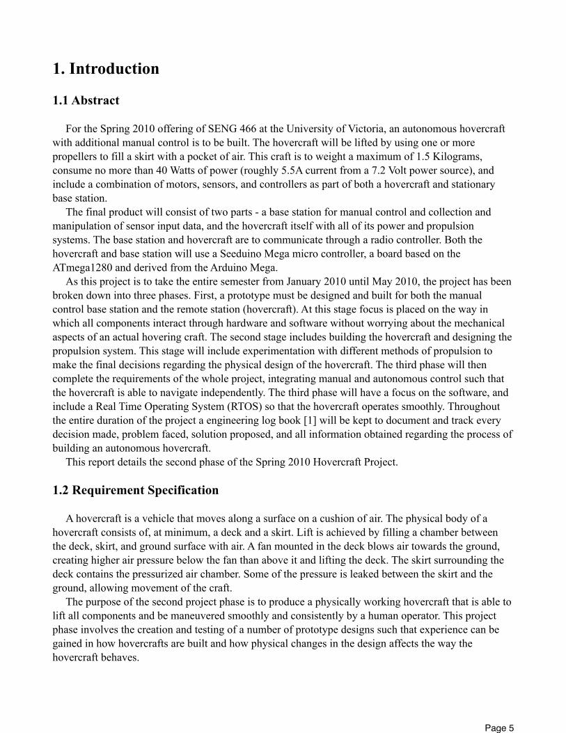
For the Spring 2010 offering of SENG 466 at the University of Victoria, an autonomous hovercraft with additional manual control is to be built. The hovercraft will be lifted by using one or more propellers to fill a skirt with a pocket of air. This craft is to weight a maximum of 1.5 Kilograms, consume no more than 40 Watts of power (roughly 5.5A current from a 7.2 Volt power source), and include a combination of motors, sensors, and controllers as part of both a hovercraft and stationary base station.
The final product will consist of two parts - a base station for manual control and collection and manipulation of sensor input data, and the hovercraft itself with all of its power and propulsion systems. The base station and hovercraft are to communicate through a radio controller. Both the hovercraft and base station will use a Seeduino Mega micro controller, a board based on the ATmega1280 and derived from the Arduino Mega.
As this project is to take the entire semester from January 2010 until May 2010, the project has been broken down into three phases. First, a prototype must be designed and built for both the manual control base station and the remote station (hovercraft). At this stage focus is placed on the way in which all components interact through hardware and software without worrying about the mechanical aspects of an actual hovering craft. The second stage includes building the hovercraft and designing the propulsion system. This stage will include experimentation with different methods of propulsion to make the final decisions regarding the physical design of the hovercraft. The third phase will then complete the requirements of the whole project, integrating manual and autonomous control such that the hovercraft is able to navigate independently. The third phase will have a focus on the software, and include a Real Time Operating System (RTOS) so that the hovercraft operates smoothly. Throughout the entire duration of the project a engineering log book [1] will be kept to document and track every decision made, problem faced, solution proposed, and all information obtained regarding the process of building an autonomous hovercraft.
This report details the second phase of the Spring 2010 Hovercraft Project.
1.2 Requirement Specification
A hovercraft is a vehicle that moves along a surface on a cushion of air. The physical body of a hovercraft consists of, at minimum, a deck and a skirt. Lift is achieved by filling a chamber between the deck, skirt, and ground surface with air. A fan mounted in the deck blows air towards the ground, creating higher air pressure below the fan than above it and lifting the deck. The skirt surrounding the deck contains the pressurized air chamber. Some of the pressure is leaked between the skirt and the ground, allowing movement of the craft.
The purpose of the second project phase is to produce a physically working hovercraft that is able to lift all components and be maneuvered smoothly and consistently by a human operator. This project phase involves the creation and testing of a number of prototype designs such that experience can be gained in how hovercrafts are built and how physical changes in the design affects the way the hovercraft behaves.
Page 5
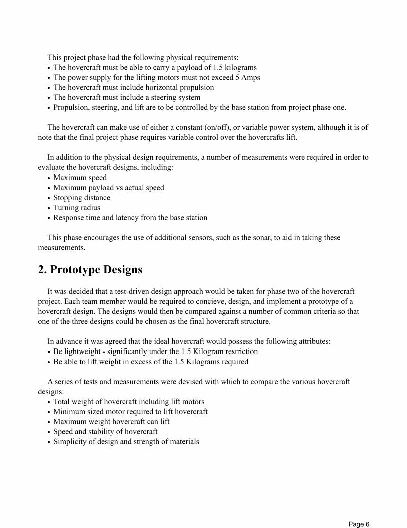
This project phase had the following physical requirements:• The hovercraft must be able to carry a payload of 1.5 kilograms• The power supply for the lifting motors must not exceed 5 Amps• The hovercraft must include horizontal propulsion• The hovercraft must include a steering system• Propulsion, steering, and lift are to be controlled by the base station from project phase one.
The hovercraft can make use of either a constant (on/off), or variable power system, although it is of note that the final project phase requires variable control over the hovercrafts lift.
In addition to the physical design requirements, a number of measurements were required in order to evaluate the hovercraft designs, including:
• Maximum speed• Maximum payload vs actual speed• Stopping distance• Turning radius• Response time and latency from the base station
This phase encourages the use of additional sensors, such as the sonar, to aid in taking these measurements.
2. Prototype Designs
It was decided that a test-driven design approach would be taken for phase two of the hovercraft project. Each team member would be required to concieve, design, and implement a prototype of a hovercraft design. The designs would then be compared against a number of common criteria so that one of the three designs could be chosen as the final hovercraft structure.
In advance it was agreed that the ideal hovercraft would possess the following attributes:• Be lightweight - significantly under the 1.5 Kilogram restriction• Be able to lift weight in excess of the 1.5 Kilograms required
A series of tests and measurements were devised with which to compare the various hovercraft designs:
• Total weight of hovercraft including lift motors• Minimum sized motor required to lift hovercraft• Maximum weight hovercraft can lift• Speed and stability of hovercraft• Simplicity of design and strength of materials
Page 6
2.1 Auroracraft
2.1.1 Concept
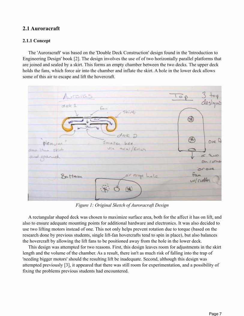
The 'Auroracraft' was based on the 'Double Deck Construction' design found in the 'Introduction to Engineering Design' book [2]. The design involves the use of of two horizontally parallel platforms that are joined and sealed by a skirt. This forms an empty chamber between the two decks. The upper deck holds the fans, which force air into the chamber and inflate the skirt. A hole in the lower deck allows some of this air to escape and lift the hovercraft.
Figure 1: Original Sketch of Auroracraft Design
A rectangular shaped deck was chosen to maximize surface area, both for the affect it has on lift, and also to ensure adequate mounting points for additional hardware and electronics. It was also decided to use two lifting motors instead of one. This not only helps prevent rotation due to torque (based on the research done by previous students, single lift-fan hovercrafts tend to spin in place), but also balances the hovercraft by allowing the lift fans to be positioned away from the hole in the lower deck.
This design was attempted for two reasons. First, this design leaves room for adjustments in the skirt length and the volume of the chamber. As a result, there isn't as much risk of falling into the trap of 'needing bigger motors' should the resulting lift be inadequate. Second, although this design was attempted previously [3], it appeared that there was still room for experimentation, and a possibility of fixing the problems previous students had encountered.
Page 7
2.1.2 Prototype
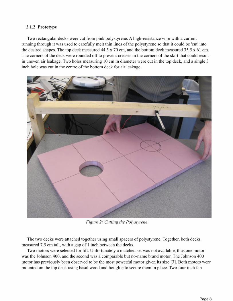
Two rectangular decks were cut from pink polystyrene. A high-resistance wire with a current running through it was used to carefully melt thin lines of the polystyrene so that it could be 'cut' into the desired shapes. The top deck measured 44.5 x 70 cm, and the bottom deck measured 35.5 x 61 cm. The corners of the deck were rounded off to prevent creases in the corners of the skirt that could result in uneven air leakage. Two holes measuring 10 cm in diameter were cut in the top deck, and a single 3 inch hole was cut in the centre of the bottom deck for air leakage.
Figure 2: Cutting the Polystyrene
The two decks were attached together using small spacers of polystyrene. Together, both decks measured 7.5 cm tall, with a gap of 1 inch between the decks.
Two motors were selected for lift. Unfortunately a matched set was not available, thus one motor was the Johnson 400, and the second was a comparable but no-name brand motor. The Johnson 400 motor has previously been observed to be the most powerful motor given its size [3]. Both motors were mounted on the top deck using basal wood and hot glue to secure them in place. Two four inch fan
Page 8
blades were chosen. Unfortunately at this time a matched set was not available, and thus a slight torque-induced rotation was still expected.
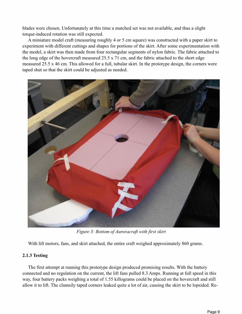
A miniature model craft (measuring roughly 4 or 5 cm square) was constructed with a paper skirt to experiment with different cuttings and shapes for portions of the skirt. After some experimentation with the model, a skirt was then made from four rectangular segments of nylon fabric. The fabric attached to the long edge of the hovercraft measured 25.5 x 71 cm, and the fabric attached to the short edge measured 25.5 x 46 cm. This allowed for a full, tubular skirt. In the prototype design, the corners were taped shut so that the skirt could be adjusted as needed.
Figure 3: Bottom of Auroracraft with first skirt
With lift motors, fans, and skirt attached, the entire craft weighed approximately 860 grams.
2.1.3 Testing
The first attempt at running this prototype design produced promising results. With the battery connected and no regulation on the current, the lift fans pulled 8.3 Amps. Running at full speed in this way, four battery packs weighing a total of 1.55 killograms could be placed on the hovercraft and still allow it to lift. The clumsily taped corners leaked quite a lot of air, causing the skirt to be lopsided. Re-
Page 9

taping the corners with more care resulted in better balance. The craft was somewhat sensitive to the precise location of weights, and the battery weights had to be placed in a symmetrical and balanced manner.
It was also noticed that the amount of air leaking from the bottom of the skirt was inadequate, and resulted in too much friction when the craft was placed on a carpeted surface.
Figure 4: Auroracraft Prototype with Skirt and Lift Motors
2.1.4 Impact on Project
The Auroracraft prototype was promising in its strength, however its weight was higher than desired. This resulted in further prototype designs being lighter, but ultimately less stable. Even at this early stage it appeared that the Auroracraft would be the final design, however it was still necessary to explore methods of fixing its faults, namely weight and friction issues.
Page 10
2.2 The Bobocraft
2.2.1 Concept
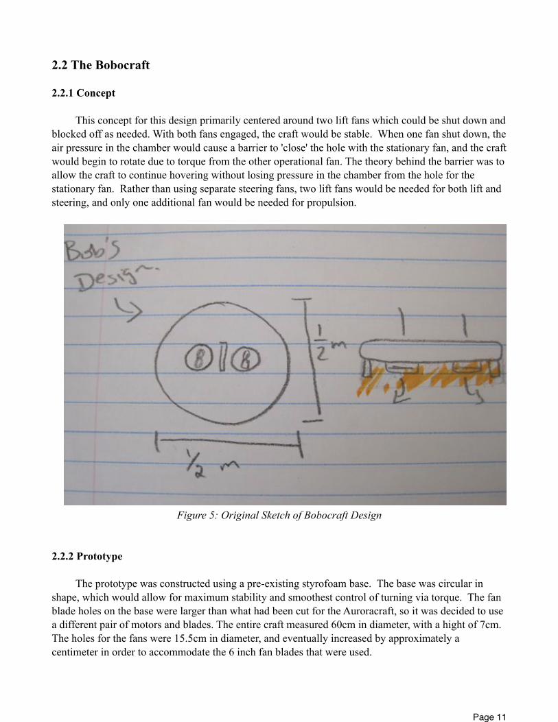
This concept for this design primarily centered around two lift fans which could be shut down and blocked off as needed. With both fans engaged, the craft would be stable. When one fan shut down, the air pressure in the chamber would cause a barrier to 'close' the hole with the stationary fan, and the craft would begin to rotate due to torque from the other operational fan. The theory behind the barrier was to allow the craft to continue hovering without losing pressure in the chamber from the hole for the stationary fan. Rather than using separate steering fans, two lift fans would be needed for both lift and steering, and only one additional fan would be needed for propulsion.
Figure 5: Original Sketch of Bobocraft Design
2.2.2 Prototype
The prototype was constructed using a pre-existing styrofoam base. The base was circular in shape, which would allow for maximum stability and smoothest control of turning via torque. The fan blade holes on the base were larger than what had been cut for the Auroracraft, so it was decided to use a different pair of motors and blades. The entire craft measured 60cm in diameter, with a hight of 7cm. The holes for the fans were 15.5cm in diameter, and eventually increased by approximately a centimeter in order to accommodate the 6 inch fan blades that were used.
Page 11

Figure 6: Polystyrene Base for Bobocraft
An attempt was made to create a pair of one way valves to sit under the lifting fans. Cardboard was cut to fit the shape of the fan holes, and then suspended under the fan using fishing line and duct tape. The fishing line was initially attached to the top of the craft. The prototyping team immediately felt foolish when the motors were lowered into place and it was found that the blades would become tangled in the fishing line. A fishing line net was also created on the bottom of the craft. This was meant to keep the stoppers reasonably close to the fan holes.
Page 12
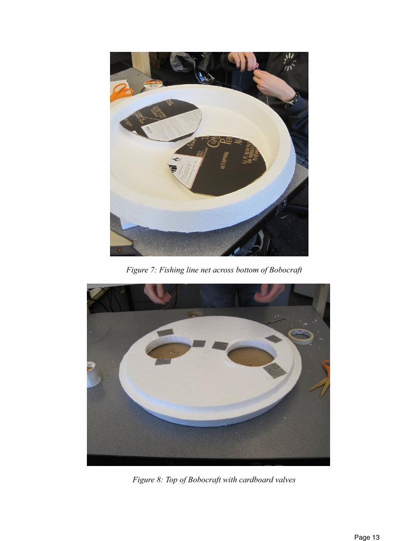
Figure 7: Fishing line net across bottom of Bobocraft
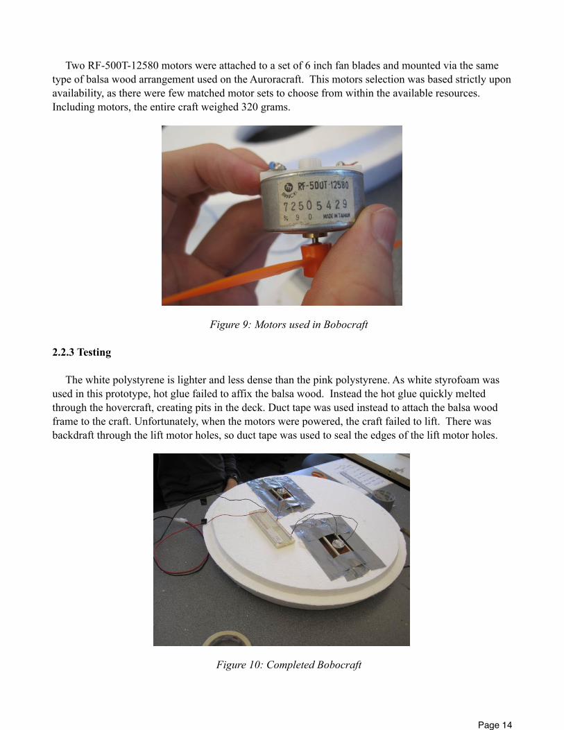
Figure 8: Top of Bobocraft with cardboard valves
Page 13
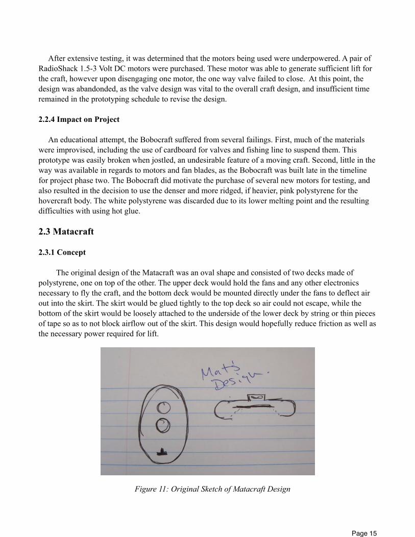
Two RF-500T-12580 motors were attached to a set of 6 inch fan blades and mounted via the same type of balsa wood arrangement used on the Auroracraft. This motors selection was based strictly upon availability, as there were few matched motor sets to choose from within the available resources. Including motors, the entire craft weighed 320 grams.
Figure 9: Motors used in Bobocraft
2.2.3 Testing
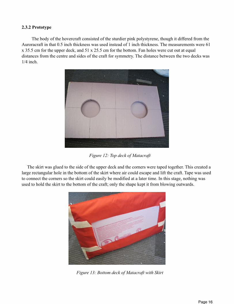
The white polystyrene is lighter and less dense than the pink polystyrene. As white styrofoam was used in this prototype, hot glue failed to affix the balsa wood. Instead the hot glue quickly melted through the hovercraft, creating pits in the deck. Duct tape was used instead to attach the balsa wood frame to the craft. Unfortunately, when the motors were powered, the craft failed to lift. There was backdraft through the lift motor holes, so duct tape was used to seal the edges of the lift motor holes.
Figure 10: Completed Bobocraft
Page 14
After extensive testing, it was determined that the motors being used were underpowered. A pair of RadioShack 1.5-3 Volt DC motors were purchased. These motor was able to generate sufficient lift for the craft, however upon disengaging one motor, the one way valve failed to close. At this point, the design was abandonded, as the valve design was vital to the overall craft design, and insufficient time remained in the prototyping schedule to revise the design.
2.2.4 Impact on Project
An educational attempt, the Bobocraft suffered from several failings. First, much of the materials were improvised, including the use of cardboard for valves and fishing line to suspend them. This prototype was easily broken when jostled, an undesirable feature of a moving craft. Second, little in the way was available in regards to motors and fan blades, as the Bobocraft was built late in the timeline for project phase two. The Bobocraft did motivate the purchase of several new motors for testing, and also resulted in the decision to use the denser and more ridged, if heavier, pink polystyrene for the hovercraft body. The white polystyrene was discarded due to its lower melting point and the resulting difficulties with using hot glue.
2.3 Matacraft
2.3.1 Concept
The original design of the Matacraft was an oval shape and consisted of two decks made of polystyrene, one on top of the other. The upper deck would hold the fans and any other electronics necessary to fly the craft, and the bottom deck would be mounted directly under the fans to deflect air out into the skirt. The skirt would be glued tightly to the top deck so air could not escape, while the bottom of the skirt would be loosely attached to the underside of the lower deck by string or thin pieces of tape so as to not block airflow out of the skirt. This design would hopefully reduce friction as well as the necessary power required for lift.
Figure 11: Original Sketch of Matacraft Design
Page 15
2.3.2 Prototype
The body of the hovercraft consisted of the sturdier pink polystyrene, though it differed from the Auroracraft in that 0.5 inch thickness was used instead of 1 inch thickness. The measurements were 61 x 35.5 cm for the upper deck, and 51 x 25.5 cm for the bottom. Fan holes were cut out at equal distances from the centre and sides of the craft for symmetry. The distance between the two decks was 1/4 inch.
Figure 12: Top deck of Matacraft
The skirt was glued to the side of the upper deck and the corners were taped together. This created a large rectangular hole in the bottom of the skirt where air could escape and lift the craft. Tape was used to connect the corners so the skirt could easily be modified at a later time. In this stage, nothing was used to hold the skirt to the bottom of the craft; only the shape kept it from blowing outwards.
Figure 13: Bottom deck of Matacraft with Skirt
Page 16
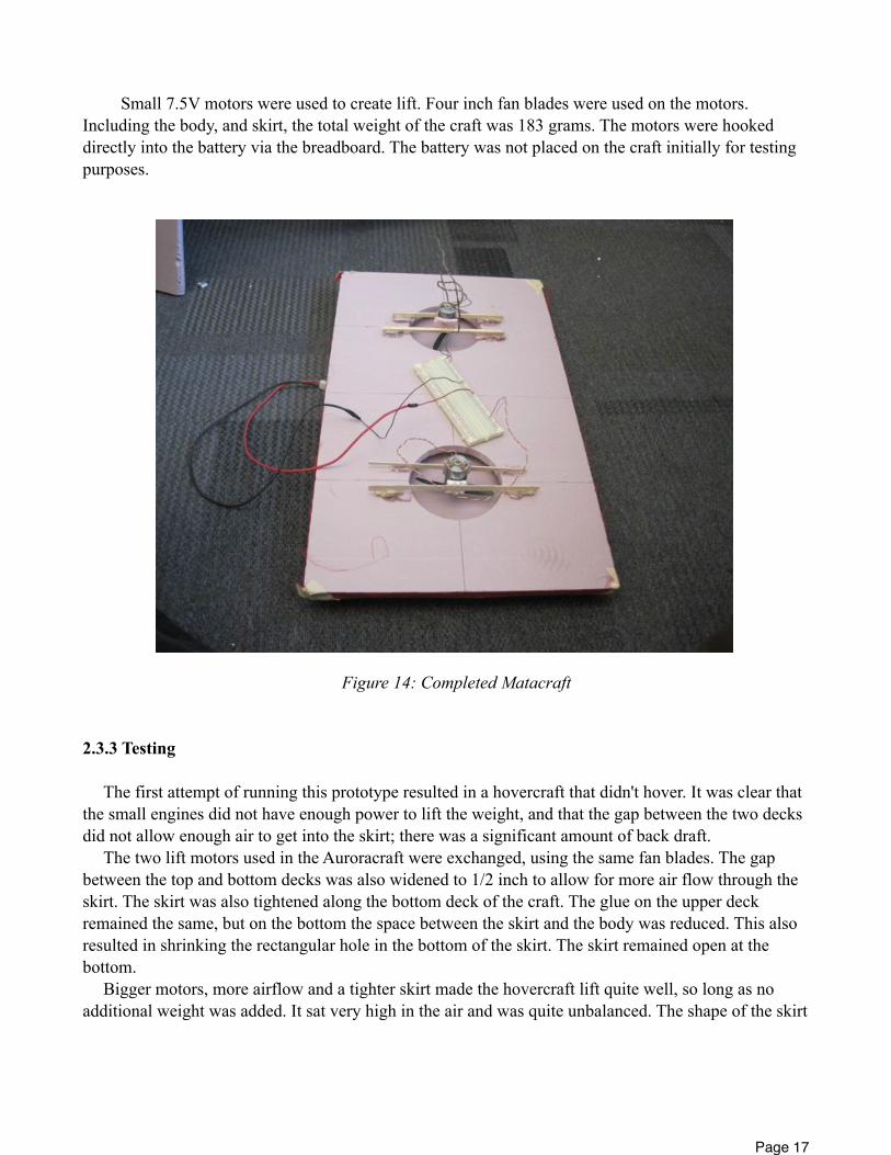
Small 7.5V motors were used to create lift. Four inch fan blades were used on the motors. Including the body, and skirt, the total weight of the craft was 183 grams. The motors were hooked directly into the battery via the breadboard. The battery was not placed on the craft initially for testing purposes.
Figure 14: Completed Matacraft
2.3.3 Testing
The first attempt of running this prototype resulted in a hovercraft that didn't hover. It was clear that the small engines did not have enough power to lift the weight, and that the gap between the two decks did not allow enough air to get into the skirt; there was a significant amount of back draft.
The two lift motors used in the Auroracraft were exchanged, using the same fan blades. The gap between the top and bottom decks was also widened to 1/2 inch to allow for more air flow through the skirt. The skirt was also tightened along the bottom deck of the craft. The glue on the upper deck remained the same, but on the bottom the space between the skirt and the body was reduced. This also resulted in shrinking the rectangular hole in the bottom of the skirt. The skirt remained open at the bottom.
Bigger motors, more airflow and a tighter skirt made the hovercraft lift quite well, so long as no additional weight was added. It sat very high in the air and was quite unbalanced. The shape of the skirt
Page 17
was such that the whole craft tipped to one side while hovering. If the battery was placed on the craft (weighing several hundred kilograms) it immediately caused the craft to fall.
In a second attempt to get the craft to lift, tape was used to secure the skirt to the bottom. This was to permit less air to escape and not cause the craft to rise so high off the ground. The idea worked well. The craft seemed more balanced and had less rise, but it still could not carry the weight of a battery, although there was some improvement in lifting additional weight than the previous design.
2.3.4 Impact on Project
The major lesson that was taken from the Matacraft design was that a tighter skirt improved stability and lift. The "pocket" under the actual craft does not need to be very large, as long as there is enough room for air to pass through it and escape evenly around the sides. This results in less friction with the floor.
This lesson was applied to the Auroracraft and it drastically decreased the amount of friction between the craft and the floor. Previously the Auroracraft could not move very quickly on carpet, nor could it be pushed by a propulsion fan. With this simple improvement to the skirt, both the front-back fan and the side-to-side fans pushed it quite easily.
3. Final Hovercraft Design
Given the criteria for selecting one final design among the prototypes, the Auroracraft was a clear choice. Although significantly heavier than the other designs, the Auroracraft was the only prototype able to lift any significant amount of weight. All three designs performed best with the larger Johnson 400 style motors. The Auroracraft proved to be the most stable design, and although not as quick as the Matacraft, the principles learned through the prototyping process could be applied to the Auroracraft to improve its speed and reduce the friction of the craft on the ground. Finally, the construction of the Auroracraft was solid, as the benefit of stronger pink polystyrene outweighed the detrimental additional weight to the craft.
3.1 Body and Skirt Design
For the final design the Auroracraft body was used with a few modifications. The gap between the top and bottom decks was reduced from 3 cm to 1.5 cm and the hole in the lower deck was increased to 14 cm to allow more air to pass under the craft.
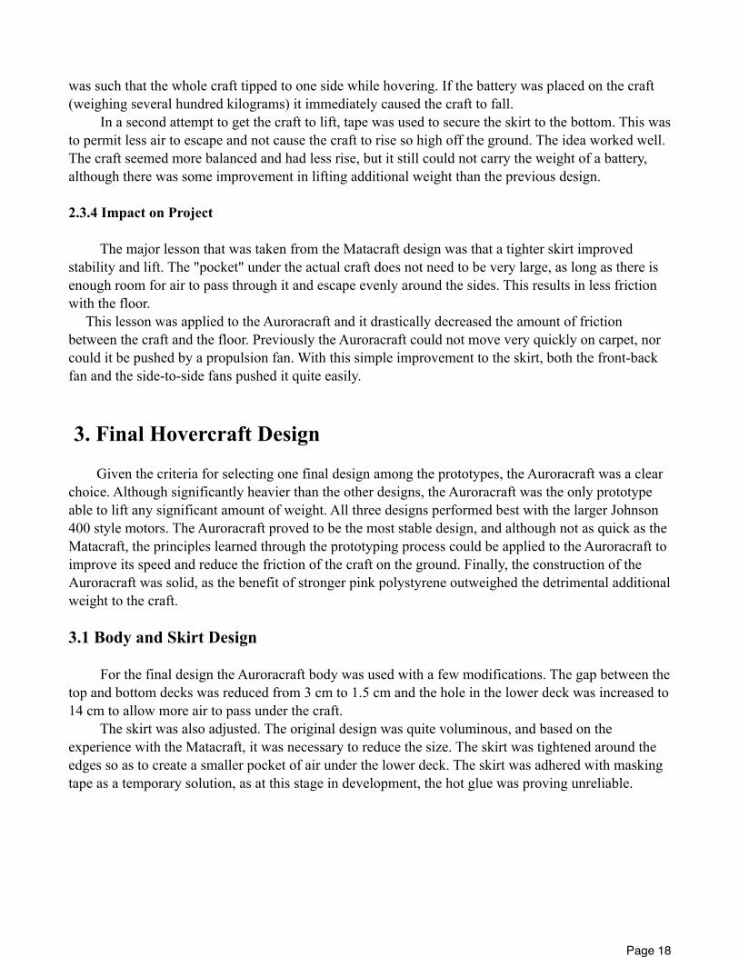
The skirt was also adjusted. The original design was quite voluminous, and based on the experience with the Matacraft, it was necessary to reduce the size. The skirt was tightened around the edges so as to create a smaller pocket of air under the lower deck. The skirt was adhered with masking tape as a temporary solution, as at this stage in development, the hot glue was proving unreliable.
Page 18
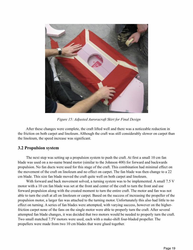
Figure 15: Adjusted Auroracraft Skirt for Final Design
After these changes were complete, the craft lifted well and there was a noticeable reduction in the friction on both carpet and linoleum. Although the craft was still considerably slower on carpet than the linoleum, the speed increase was significant.
3.2 Propulsion system
The next step was setting up a propulsion system to push the craft. At first a small 10 cm fan blade was used on a no-name brand motor (similar to the Johnson 400) for forward and backwards propulsion. No fan ducts were used for this stage of the craft. This combination had minimal effect on the movement of the craft on linoleum and no effect on carpet. The fan blade was then change to a 22 cm blade. This size fan blade moved the craft quite well on both carpet and linoleum.
With forward and back movement solved, a turning system was to be implemented. A small 7.5 V motor with a 10 cm fan blade was set at the front and center of the craft to turn the front and use forward propulsion along with the created moment to turn the entire craft. The motor and fan was not able to turn the craft at all on linoleum or carpet. Based on the success of increasing the propeller of the propulsion motor, a larger fan was attached to the turning motor. Unfortunately this also had little to no effect on turning. A series of fan blades were attempted, with varying success, however on the higher-friction carpet none of the fans on the single motor were able to properly turn the craft. After several attempted fan blade changes, it was decided that two motors would be needed to properly turn the craft. Two small matched 7.5V motors were used, each with a make-shift four-bladed propeller. The propellers were made from two 10 cm blades that were glued together.
Page 19
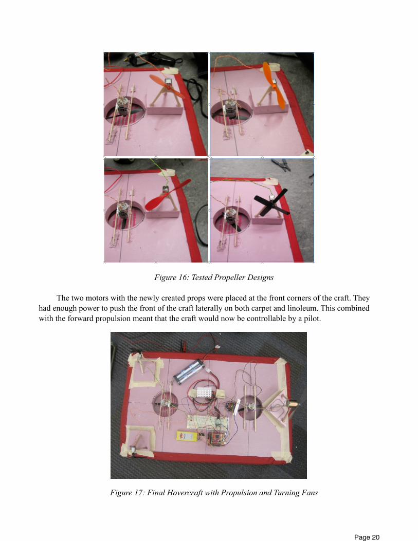
Figure 16: Tested Propeller Designs
The two motors with the newly created props were placed at the front corners of the craft. They had enough power to push the front of the craft laterally on both carpet and linoleum. This combined with the forward propulsion meant that the craft would now be controllable by a pilot.
Figure 17: Final Hovercraft with Propulsion and Turning Fans
Page 20
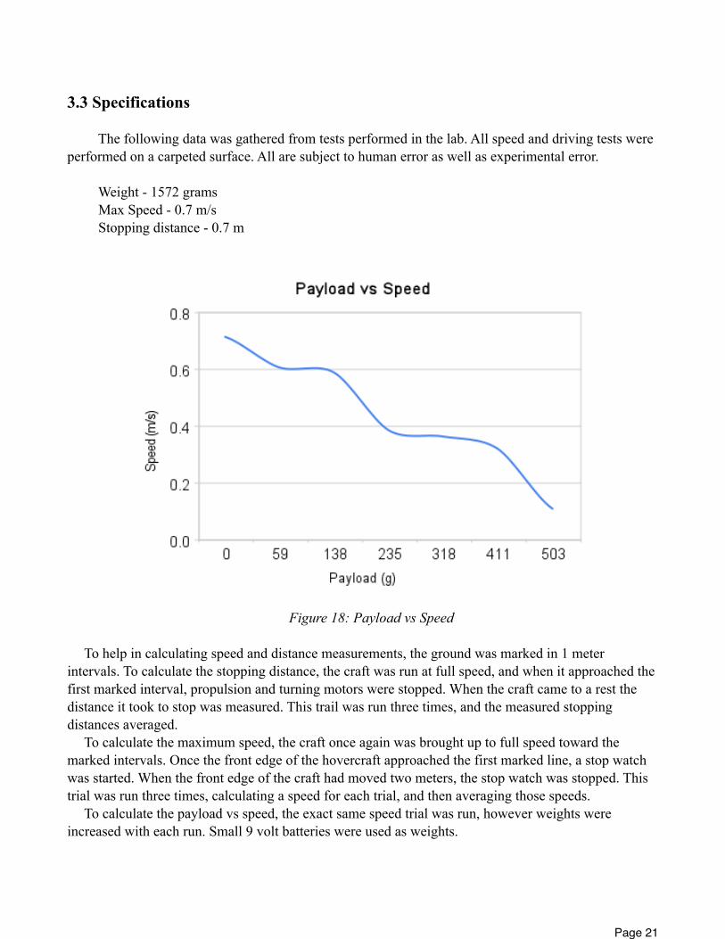
3.3 Specifications
The following data was gathered from tests performed in the lab. All speed and driving tests were performed on a carpeted surface. All are subject to human error as well as experimental error.
Weight - 1572 grams Max Speed - 0.7 m/s Stopping distance - 0.7 m
Figure 18: Payload vs Speed
To help in calculating speed and distance measurements, the ground was marked in 1 meter intervals. To calculate the stopping distance, the craft was run at full speed, and when it approached the first marked interval, propulsion and turning motors were stopped. When the craft came to a rest the distance it took to stop was measured. This trail was run three times, and the measured stopping distances averaged.
To calculate the maximum speed, the craft once again was brought up to full speed toward the marked intervals. Once the front edge of the hovercraft approached the first marked line, a stop watch was started. When the front edge of the craft had moved two meters, the stop watch was stopped. This trial was run three times, calculating a speed for each trial, and then averaging those speeds.
To calculate the payload vs speed, the exact same speed trial was run, however weights were increased with each run. Small 9 volt batteries were used as weights.
Page 21
The craft was surprisingly consistent in all trials, with speed and distance runs producing almost identical results each time. The most deviation occurred in the payload vs speed trials, as the hovercraft appears very sensitive to changes in weight distribution.
3.4 Problems and Future Considerations
A major problem for this version of the craft that must be dealt with in the next iteration is weight. The maximum allowed weight for the final design is 1500 grams. The current weight is 72 grams over that amount. To remedy this, a new breadboard is going to be used. The smaller board is lighter by 80 grams than the standard breadboard, bringing the craft back under the weight limit. Also, excess polystyrene can be removed from the steering fans. A base was built for each fan such that longer blades had room to rotate, but these bases are no longer required for the current fan configuration. More polystyrene will be removed by creating divots in the craft for parts such as batteries and boards. Because more sensors need to be added, it is unknown if more weight will need to be lost. Making the whole craft smaller is a last resort, as it could affect how much payload can be lifted.
An improvement to the drive of the craft could be made by replacing fan ducts for the propulsion fans. The lift motors are already surrounded by the actual body, so they don't need any attention in this respect, however the propulsion fans have no such enclosure. Duct fans for the turning fans will increase their effectiveness drastically [3].
It is also desirable to find a matched set of opposing fan blades for the lift motors. Currently the blades used are identical, and thus any pilot driving the craft must compensate for a small amount of rotational torque. The fan blade sets are scarce in the lab, and visiting a local hobby shop was also unsuccessful. Continued effort will be put into finding appropriate fan blades.
The last problem is the amount of current being drawn from the motors. The two lift motors alone are drawing 8.3 amps. This is far too much. Running the lift fans through the motor driver at 5 Amps does not create enough lift either. We have not yet found a solution to this problem, but it must be addressed in the next iteration of the craft.
3.5 Additional Building Lessons
A common problem for all of the prototype designs was properly adhering the skirt material to the body of the hovercraft. The skirt material used was a slightly textured nylon fabric. The hovercraft bodies all used either white or pink polystyrene. The white polystyrene is less dense and lighter, while the pink polystyrene was heavier but did not flex as much.
To help in deciding how best to adhere the nylon skirt to the body of the hovercraft, sections of fabric were tested with a variety of adhesives.
Loctite was brushed onto the nylon fabric and attached to the styrofoam. Tugging the fabric did not separate it from the styrofoam, and proved to be secure. Unfortunately, as only a small bottle was available, it was not used. Plastic model cement was also tested, but melted the polystyrene instantly upon contact. This option was quickly discarded. Hot glue applied directly to the polystyrene proved initially as effective as loctite. Tugging on the fabric did not immediately disengage the materials, and furthermore the glue was in great abundance. Over time however, the glue was not as effective, and the materials were easily separated. This proved useful later on in skirt modifications, but the final solution was to tape all seams with standard masking tape.
Page 22

4. Software Updates and Changes
Though the same basic architecture was used in phase two as in phase one, a few key modifications were made to the hovercraft codebase. The basestation code was left unchanged. The modified hovercraft code can be found in the appendix.
4.1 Code Changes
The servo code was removed, as no servo is used in the phase two design. Several variable names were changed to avoid confusion. An additional piece of code was added to the radio handler to map left-right input to the steering motors. Sonar checks were commented out as the phase two craft doesn't use sonar. Sonar will be added back during phase three.
4.2 Difficulty In Adapting Code
During the integration testing of phrase two, it was found that our propulsion motor remained in the 'full on' state at all times. Initially, it was assumed that there was an error in the threshold value for determining which direction the motor should be moving. After further testing, the problem was narrowed down to the hovercraft always setting the value of pin 0 and 1 as binary, despite being set as analog values in the code. A more thorough examination of the Arduino board showed that pins 0 and 1, despite being next to the PWM pins, do not serve as PWM pins themselves. The board wiring was rearranged to accommodate this, and several constants were changed in code to accommodate the new pin numbers.
5. References[1] M. Conyers, A. Walker, B. Warwick. Mechatronics Lab Book. http://docs.google.com/View?id=dg3cjxnm_64hqnkwpg3
[2] J. Dally, K. Calabro, W. Fourney, G. Pertmer, G. Zhang. Introduction to Engineering Design, Book 9 2nd edition. Engineering Skills and Hovercraft Missions. College House Enterprises, LLC Knoxville Tennessee. 2007.
[3] J. Hawthorn, J. Oram, T. Sullivan. Seng 466 Mechatronics Project 2. http://webhome.csc.uvic.ca/~mcheng/samples/hawthorn/project2.pdf
Page 23
Appendix
/* Hover-‐zors *//* Janaury 29, 2010 */
#include "avr_h/Wire/Wire.h"#include "avr_h/radio/radio.h"#include "avr_h/radio/packet.h"#include "avr_h/WProgram.h"#include <math.h>
#define JOYSTICK_TRIGGER_BUTTON 3#define JOYSTICK_THUMB_BUTTON 2#define JOYSTICK_LEFT_RIGHT_AXIS 1#define JOYSTICK_FRONT_BACK_AXIS 0
#define FORWARD_BACK_MOTOR_ENABLE 3#define FORWARD_BACK_MOTOR_PIN_1 22#define FORWARD_BACK_MOTOR_PIN_2 23#define LEFT_RIGHT_MOTOR_ENABLE 4#define LEFT_RIGHT_MOTOR_PIN_1 5#define LEFT_RIGHT_MOTOR_PIN_2 6#define FORE_LIFT_MOTOR_ENABLE 9#define FORE_LIFT_MOTOR_I1 10#define FORE_LIFT_MOTOR_I2 11#define AFT_LIFT_MOTOR_ENABLE 12#define AFT_LIFT_MOTOR_I1 38#define AFT_LIFT_MOTOR_I2 39
int ledPin = 13; // LED connected to digital pin 13 bool liftOn = false; // Bool for controlling when to turn on and turn off the lift fan // Yeah guys, we totally wouldn't know this was a bool without this comment
int nearReads = 0, farReads = 0; // Helps throw away garbage sonar readings
uint8_t tx_addr[RADIO_ADDRESS_LENGTH] = { 0xC0, 0xFF, 0xEE, 0xBA, 0xBE };uint8_t rx_addr[RADIO_ADDRESS_LENGTH] = { 0xC0, 0xFF, 0xEE, 0xB0, 0xB5 };radiopacket_t packet;int messageID = 1;char packetBuffer[23];int inches = 24, sonarRead = 0;
struct packetData { int packetType; int packetValue;};
extern "C" void __cxa_pure_virtual(void) { while(1);}
Page 24
void setup(){
delay(5000);
Serial.begin(9600); Serial.println("Began Setup");
// Prepare the radio for pure receive-‐y goodness Radio_Init(); Radio_Configure_Rx(RADIO_PIPE_0, rx_addr, ENABLE); Radio_Configure(RADIO_2MBPS, RADIO_HIGHEST_POWER); Radio_Set_Tx_Addr(tx_addr);
pinMode(FORE_LIFT_MOTOR_I1, OUTPUT); pinMode(FORE_LIFT_MOTOR_I2, OUTPUT); pinMode(FORE_LIFT_MOTOR_ENABLE, OUTPUT); pinMode(AFT_LIFT_MOTOR_I1, OUTPUT); pinMode(AFT_LIFT_MOTOR_I2, OUTPUT); pinMode(AFT_LIFT_MOTOR_ENABLE, OUTPUT); pinMode(FORWARD_BACK_MOTOR_PIN_1, OUTPUT); pinMode(FORWARD_BACK_MOTOR_PIN_2, OUTPUT); pinMode(LEFT_RIGHT_MOTOR_PIN_1, OUTPUT); pinMode(LEFT_RIGHT_MOTOR_PIN_2, OUTPUT);
pinMode(ledPin, OUTPUT); digitalWrite(ledPin, LOW); // set the LED to OFF! OFF I SAY YOU FOOL!
digitalWrite(FORE_LIFT_MOTOR_ENABLE, HIGH); digitalWrite(FORE_LIFT_MOTOR_I1, LOW); digitalWrite(FORE_LIFT_MOTOR_I2, HIGH); digitalWrite(AFT_LIFT_MOTOR_ENABLE, HIGH); digitalWrite(AFT_LIFT_MOTOR_I1, LOW); digitalWrite(AFT_LIFT_MOTOR_I2, HIGH); //digitalWrite(FORWARD_BACK_MOTOR_ENABLE, LOW); digitalWrite(FORWARD_BACK_MOTOR_PIN_1, LOW); digitalWrite(FORWARD_BACK_MOTOR_PIN_2, LOW); //digitalWrite(LEFT_RIGHT_MOTOR_ENABLE, LOW); digitalWrite(LEFT_RIGHT_MOTOR_PIN_1, LOW); digitalWrite(LEFT_RIGHT_MOTOR_PIN_2, LOW);
}
void loop(){/* Commented out sonar section, currently not in use */// sonarRead = analogRead(SONAR_INPUT);// inches = sonarRead/2;// Serial.print(" Inches away: ");// Serial.println(inches);
/*
if (inches < 12){ nearReads ++;
Page 25
farReads = 0; //deal with noise. Make sure 3 small ones in a row if(nearReads > 4){ Radio_Configure_Rx(RADIO_PIPE_0, rx_addr, DISABLE); analogWrite(VERTICAL_MOTOR_ENABLE, 0); analogWrite(LIFT_MOTOR_ENABLE, 0); liftOn = false; nearReads = 0; } }else{ nearReads = 0; farReads++; if(farReads > 4){ Radio_Configure_Rx(RADIO_PIPE_0, rx_addr, ENABLE); farReads = 0; } }
*/}
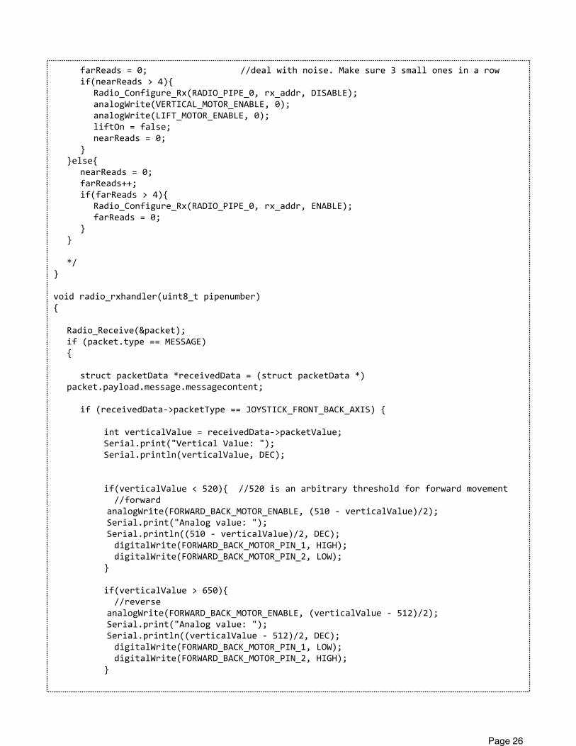
void radio_rxhandler(uint8_t pipenumber){
Radio_Receive(&packet); if (packet.type == MESSAGE) {
struct packetData *receivedData = (struct packetData *) packet.payload.message.messagecontent;
if (receivedData-‐>packetType == JOYSTICK_FRONT_BACK_AXIS) {
int verticalValue = receivedData-‐>packetValue; Serial.print("Vertical Value: "); Serial.println(verticalValue, DEC);
if(verticalValue < 520){ //520 is an arbitrary threshold for forward movement //forward analogWrite(FORWARD_BACK_MOTOR_ENABLE, (510 -‐ verticalValue)/2); Serial.print("Analog value: "); Serial.println((510 -‐ verticalValue)/2, DEC); digitalWrite(FORWARD_BACK_MOTOR_PIN_1, HIGH); digitalWrite(FORWARD_BACK_MOTOR_PIN_2, LOW); }
if(verticalValue > 650){ //reverse analogWrite(FORWARD_BACK_MOTOR_ENABLE, (verticalValue -‐ 512)/2); Serial.print("Analog value: "); Serial.println((verticalValue -‐ 512)/2, DEC); digitalWrite(FORWARD_BACK_MOTOR_PIN_1, LOW); digitalWrite(FORWARD_BACK_MOTOR_PIN_2, HIGH); }
Page 26
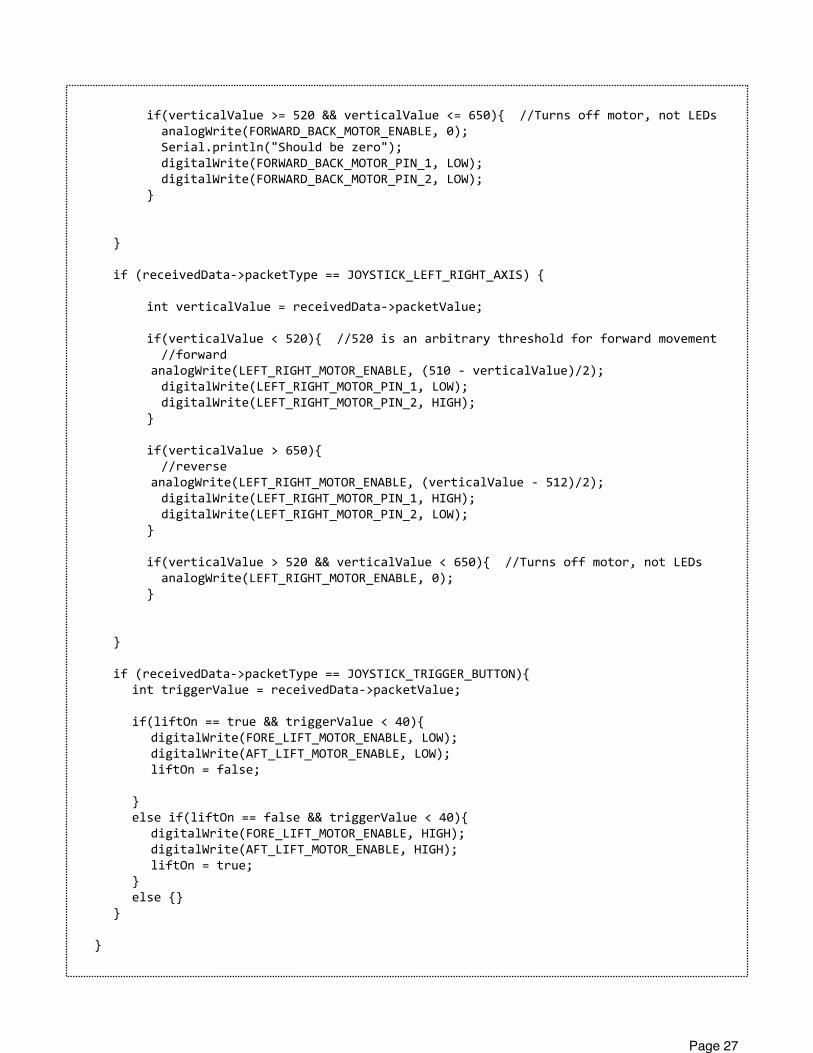
if(verticalValue >= 520 && verticalValue <= 650){ //Turns off motor, not LEDs analogWrite(FORWARD_BACK_MOTOR_ENABLE, 0); Serial.println("Should be zero"); digitalWrite(FORWARD_BACK_MOTOR_PIN_1, LOW); digitalWrite(FORWARD_BACK_MOTOR_PIN_2, LOW); }
}
if (receivedData-‐>packetType == JOYSTICK_LEFT_RIGHT_AXIS) {
int verticalValue = receivedData-‐>packetValue;
if(verticalValue < 520){ //520 is an arbitrary threshold for forward movement //forward analogWrite(LEFT_RIGHT_MOTOR_ENABLE, (510 -‐ verticalValue)/2); digitalWrite(LEFT_RIGHT_MOTOR_PIN_1, LOW); digitalWrite(LEFT_RIGHT_MOTOR_PIN_2, HIGH); }
if(verticalValue > 650){ //reverse analogWrite(LEFT_RIGHT_MOTOR_ENABLE, (verticalValue -‐ 512)/2); digitalWrite(LEFT_RIGHT_MOTOR_PIN_1, HIGH); digitalWrite(LEFT_RIGHT_MOTOR_PIN_2, LOW); }
if(verticalValue > 520 && verticalValue < 650){ //Turns off motor, not LEDs analogWrite(LEFT_RIGHT_MOTOR_ENABLE, 0); }
}
if (receivedData-‐>packetType == JOYSTICK_TRIGGER_BUTTON){ int triggerValue = receivedData-‐>packetValue;
if(liftOn == true && triggerValue < 40){ digitalWrite(FORE_LIFT_MOTOR_ENABLE, LOW); digitalWrite(AFT_LIFT_MOTOR_ENABLE, LOW); liftOn = false;
} else if(liftOn == false && triggerValue < 40){ digitalWrite(FORE_LIFT_MOTOR_ENABLE, HIGH); digitalWrite(AFT_LIFT_MOTOR_ENABLE, HIGH); liftOn = true; } else {} }
}
Page 27
}
int main(void){
init(); setup(); for(;;){ loop(); }}
Page 28