Embed Size (px)
Citation preview
2750 IEEE TRANSACTIONS ON MAGNETICS, VOL. 45, NO. 6, JUNE 2009
Cogging Force Reduction of a Stationary DiscontinuousArmature PM-LSM by Magnet Segmentation
Yong-Jae Kim�, Suk-seung Hwang�, and Yu-Seok Jeong�
Department of Electrical Engineering, Chosun University, Gwangju 501-759, KoreaDepartment of Mechatronics Engineering, Chosun University, Gwangju 501-759, Korea
Department of Electrical Engineering, MyongJi University, Yongin 449-728, Korea
Recently, permanent magnet type linear synchronous motors have been used as a driving source of transportation systems, to satisfyrequirements such as speeding up of transportation systems and also to simplify maintenance. The authors’ laboratory has proposeda stationary discontinuous armature PM-LSM in which the armature is engaged only when accelerated and decelerated operation isnecessary, in order to resolve the problem of higher costs, when PM-LSM is used with long-distance transportation systems in factories.However, the stationary discontinuous armature PM-LSM contains the outlet edges which always exist as a result of the discontinuousarrangement of the armature. These edges become a problem, because the cogging force that they exert influences the controllability ofthe motor. This paper presents the results of an experimental examination and three-dimensional numerical analysis by the finite elementmethod of the cogging force exerted by the outlet edge. Moreover, we modified the permanent magnet on the mover to decrease thecogging force at the outlet edge, and the results are examined using three-dimensional numerical analysis by the finite element method.
Index Terms—Cogging force, discontinuous arrangement, energy conversion, linear synchronous motor, outlet edge, skew, three-di-mensional numerical analysis.
I. INTRODUCTION
L INEAR motors have become popular in the field offactory automation (FA) where there is great demand
for high-speed, low noise, simplification of driving apparatusand maintenance-free transportation [1], [2]. Linear inductionmotors (LIM), which obtain high thrust force and have a simplestructure, have become the main linear motors in this field[3]. However, besides heavy load transportation and horizontaltransportation, the usage of slanted and vertical transportationis recently increasing. Furthermore, there is increasing demandfor positioning accuracy in transportation systems and a lotof attention has been focused on linear synchronous motors(LSM) [4]–[9]. We have also been engaged in enhancing trans-portation applications of permanent magnet linear synchronousmotors (PM-LSM) using high-energy magnetic materials. Suchmotors offer higher efficiency than LIMs, and they also haveposition-hold stability when at rest.
Usually, in a transportation system using linear motors, afull-length (continuous) armature-side-on-ground design isemployed. This design is very reliable although it is costly inlong-distance transportation systems. However, a discontin-uous arrangement is favorable in a long-distance system unlessconstant-speed requirements are very strict. Thus, in order toresolve the problem of higher costs, the authors’ laboratoryhas proposed a stationary discontinuous armature PM-LSMin which the armature is engaged only when accelerated anddecelerated operation is necessary, when PM-LSM is used withlong-distance transportation systems in factories [10], [11].Fig. 1 shows speed profiles of PM-LSM horizontal transporta-tion systems. However, the stationary discontinuous armaturePM-LSM contains the outlet edges which always exist as a
Manuscript received October 09, 2008. Current version published May 20,2009. Corresponding author: S.-S. Hwang (e-mail: [email protected]).
Color versions of one or more of the figures in this paper are available onlineat http://ieeexplore.ieee.org.
Digital Object Identifier 10.1109/TMAG.2009.2020547
result of the discontinuous arrangement of the armature. Forthis reason, cogging force generated between the “entranceend (entry interval)” and the “exit end (ejection interval)” hasbecome a problem. The problem is that the cogging force thatoperates at each outlet edge affects the mover’s drive, and thereis a possibility that hunting occurs during acceleration anddeceleration when freewheeling changes over to re-accelerationand deceleration [12]. Particularly, hunting acts as the majorfactor of vibration and noise and, in the worst case, causesstep out due to load disturbance. Therefore, the reduction ofcogging force at each outlet edge is highly desirable in order toprevent the possibility of hunting occurring at the re-acceleratorand decelerator and this allows stable drive of the stationarydiscontinuous armature PM-LSM. Recently, researchers haveproposed some methods for reducing cogging force withregular periodicity which affects machine output or drivingcharacteristics [13]–[16]. One of them provides skew for per-manent magnets or cores, and another changes the magnetic endarrangement. Therefore, in order to reduce the cogging forceproduced at the outlet edge, skew was applied on the permanentmagnet of the mover and its effect on the cogging force of theoutlet edge was carefully examined. It is used to analyze thewaveforms of the cogging force that operate at each outlet edgeresulting in 17-slots, 4-pole stationary discontinuous armaturePM-LSM and also to demonstrate the utility of incorporatingskew by displacing the two magnet segments of each pole. Thispaper presents the results of three-dimensional (3-D) numericalanalysis by the finite element method (FEM) of the coggingforce exerted by the outlet edge. Moreover, we modified thepermanent magnet on the mover to decrease the cogging forceat the outlet edge, and its results were examined using 3-Dnumerical analysis by the FEM.
II. FORCE GENERATED AT THE OUTLET EDGE OF THE
STATIONARY DISCONTINUOUS ARMATURE PM-LSM
The armature arrangement of the stationary discontinuous ar-mature PM-LSM is given schematically in Fig. 2. The moveris accelerated by the short armature unit (accelerator) and is
0018-9464/$25.00 © 2009 IEEE
KIM et al.: COGGING FORCE REDUCTION OF A STATIONARY DISCONTINUOUS ARMATURE PM-LSM BY MAGNET SEGMENTATION 2751
Fig. 1. Speed profiles of PM-LSM horizontal transportation systems.
Fig. 2. Schematic representations of armature unit.
Fig. 3. Forces exerted in the mover at the outlet edge. (a) Entry interval (en-trance end). (b) Ejection interval (exit end).
then driven by its own inertia. Since the velocity of the moverdecreases, the mover enters the next armature unit which isinstalled in order to make it re-accelerate and decelerate, andthere it is re-accelerated and decelerated. However, if the movergoes through the boundary between the installation part andthe non-installation part of the armature at stationary discontin-uous armature PM-LSM, the attractive force produced betweenthe armature’s core and mover’s permanent magnet fluctuateshighly. The attractive force produced at the entry interval op-erates in the same direction as the mover. That is, the moveris accelerated by the force that pulls the mover into the arma-ture area. On the other hand, the attractive force generated at theejection interval operates in the opposite direction to the mover.In other words, the mover becomes decelerated by the force,which pulls back the mover to the armature area. Fig. 3 showsforces exerted in the mover at the outlet edge. This attractiveforce can be divided into two different forces: a) the coggingforce produced in the same direction as the PM-LSM’s thrustforce (the direction of a -axis) between the permanent magnetand the armature’s core and b) the normal force produced in thedirection of an air-gap (the direction of a -axis) between thepermanent magnet and the armature’s core. Due to the effect ofthe cogging force that operates at the outlet edge, it has becomea problem that the velocity of the mover is different from that ofthe velocity command during re-acceleration and decelerationwhen the mover changes from freewheeling to re-accelerationand deceleration [12].
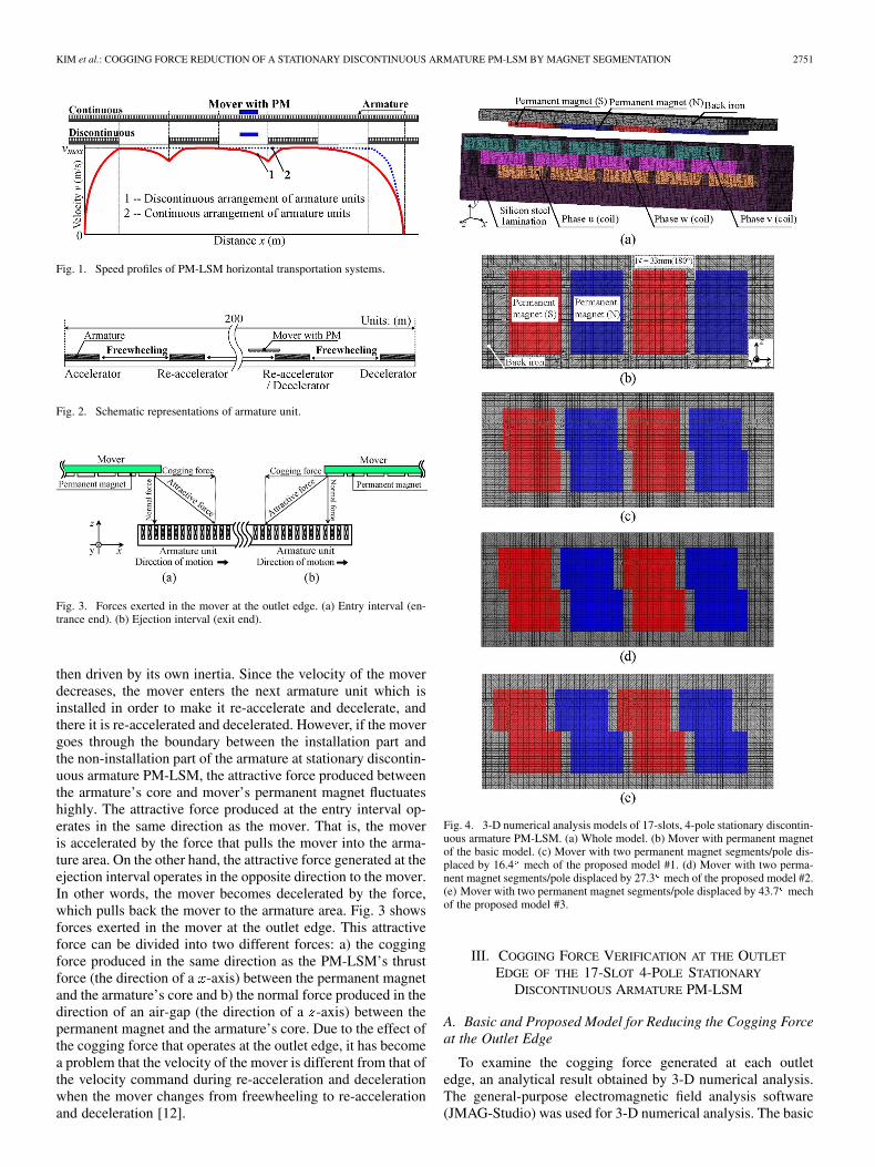
Fig. 4. 3-D numerical analysis models of 17-slots, 4-pole stationary discontin-uous armature PM-LSM. (a) Whole model. (b) Mover with permanent magnetof the basic model. (c) Mover with two permanent magnet segments/pole dis-placed by 16.4 mech of the proposed model #1. (d) Mover with two perma-nent magnet segments/pole displaced by 27.3 mech of the proposed model #2.(e) Mover with two permanent magnet segments/pole displaced by 43.7 mechof the proposed model #3.
III. COGGING FORCE VERIFICATION AT THE OUTLET
EDGE OF THE 17-SLOT 4-POLE STATIONARY
DISCONTINUOUS ARMATURE PM-LSM
A. Basic and Proposed Model for Reducing the Cogging Forceat the Outlet Edge
To examine the cogging force generated at each outletedge, an analytical result obtained by 3-D numerical analysis.The general-purpose electromagnetic field analysis software(JMAG-Studio) was used for 3-D numerical analysis. The basic
2752 IEEE TRANSACTIONS ON MAGNETICS, VOL. 45, NO. 6, JUNE 2009
TABLE IDIMENSIONS OF 3-D NUMERICAL ANALYSIS MODELS
Fig. 5. Cogging force waveform in the basic model (4 poles, 17 slots). “RegionA” is the entry interval (Entrance end), “Region B” is the complete alignmentof the mover with the armature interval and “Region C” is the ejection interval(Exit end). “� ” is the position immediately before the mover passes the exitend of the armature and “� ” is the position of the mover after it has completelypassed the exit end of the armature (m).
model and proposed model for reducing the cogging force atthe outlet edge used for the 3-D numerical analysis are shownin Fig. 4, and the dimensions of 3-D numerical analysis modelsare listed in Table I. The armature used for measurement has 17slots and 4-pole permanent magnets which are arranged in themover. The permanent magnets provideand the pole pitch is 33 mm (180 ), and air-gap is 5 mmbetween the armature and the mover. Also, the pitch of thearmature’s slot is 11 mm. The pitch of this slot is 60 mechcompared to the pole pitch and 1 cycle of the cogging force isproduced with 60 cycle when the mover and the armature arealigned. Therefore, to reduce the cogging force produced at theoutlet edge, the permanent magnet arranged in the mover of theproposed model was divided into two sections: upper and lowerdivisions according to the directions of motion (the directionof an x-axis). Moreover, the permanent magnet was shifted inorder to create a stair shape image by using the skew angle. Asthe cogging force produced during the alignment has 1 cycleof 60 , we selected 3 skew angles within 60 for examination.The skew angles used in this paper were 16.4 , 27.3 and 43.7mech. We made a full scale model using the general-purposeelectromagnetic field analysis software and performed 3-D nu-merical analysis using the FEM on each of them. The numberof elements is 261337, and the number of nodes is 137649. Theamount of movement per step is an interval of 1 mm. Also, notethat ejection interval was the only analysis range consideredfor the proposed model and the analysis of the cogging force ofeach proposed model were compared with the basic one.
B. Three-Dimensional Numerical Analysis Results
The shape of the cogging force waveform at all regions madein the basic model with a 3-D numerical analysis by the FEM isshown in Fig. 5. As indicated by Fig. 5, the cogging force at the
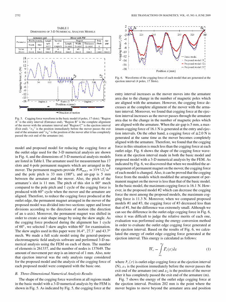
Fig. 6. Waveforms of the cogging force of each model that are generated at theejection interval (4 poles, 17 Slots).
entry interval increases as the mover moves into the armaturearea due to the change in the number of magnetic poles whichare aligned with the armature. However, the cogging force de-creases at the complete alignment of the mover with the arma-ture interval. Moreover, we found that cogging force at the ejec-tion interval increases as the mover passes through the armaturearea due to the change in the number of magnetic poles whichare aligned with the armature. When the air-gap is 5 mm, a max-imum cogging force of 16.1 N is generated at the entry and ejec-tion intervals. On the other hand, a cogging force of 2.0 N isgenerated at the same time as the mover becomes completelyaligned with the armature. Therefore, we found that the coggingforce in this situation is much less than the cogging force at eachoutlet edge. Fig. 6 shows the shape of the cogging force wave-form at the ejection interval made in both the basic model andproposed model with a 3-D numerical analysis by the FEM. Asindicated by Fig. 6, we discovered that when we modified the ar-rangement of permanent magnet on the mover, the cogging forceof each model is changed. Also, it can be proved that the coggingforce from the models which modified the arrangement of per-manent magnet on the mover is less than that of the basic model.In the basic model, the maximum cogging force is 16.1 N. How-ever, in the proposed model #2 which can decrease the coggingforce the most among the proposed models, the maximum cog-ging force is 11.3 N. Moreover, when we compared proposedmodels #1 and #3, the cogging force of #3 decreased less thanthat of #1, but the difference was extremely small. Although wecan see the difference in the outlet edge cogging force in Fig. 6,since it was difficult to judge the relative merits of each one,evaluation was performed using the energy conversion methodin order to evaluate the outlet edge cogging force generated atthe ejection interval. Based on the results of Fig. 6, we calcu-lated the energy of outlet edge cogging force generated at theejection interval. This energy is calculated as follows:
(1)
where is outlet edge cogging force at the ejection interval(N), is the position immediately before the mover passes theexit end of the armature (m) and is the position of the moverafter it has completely passed the exit end of the armature (m).
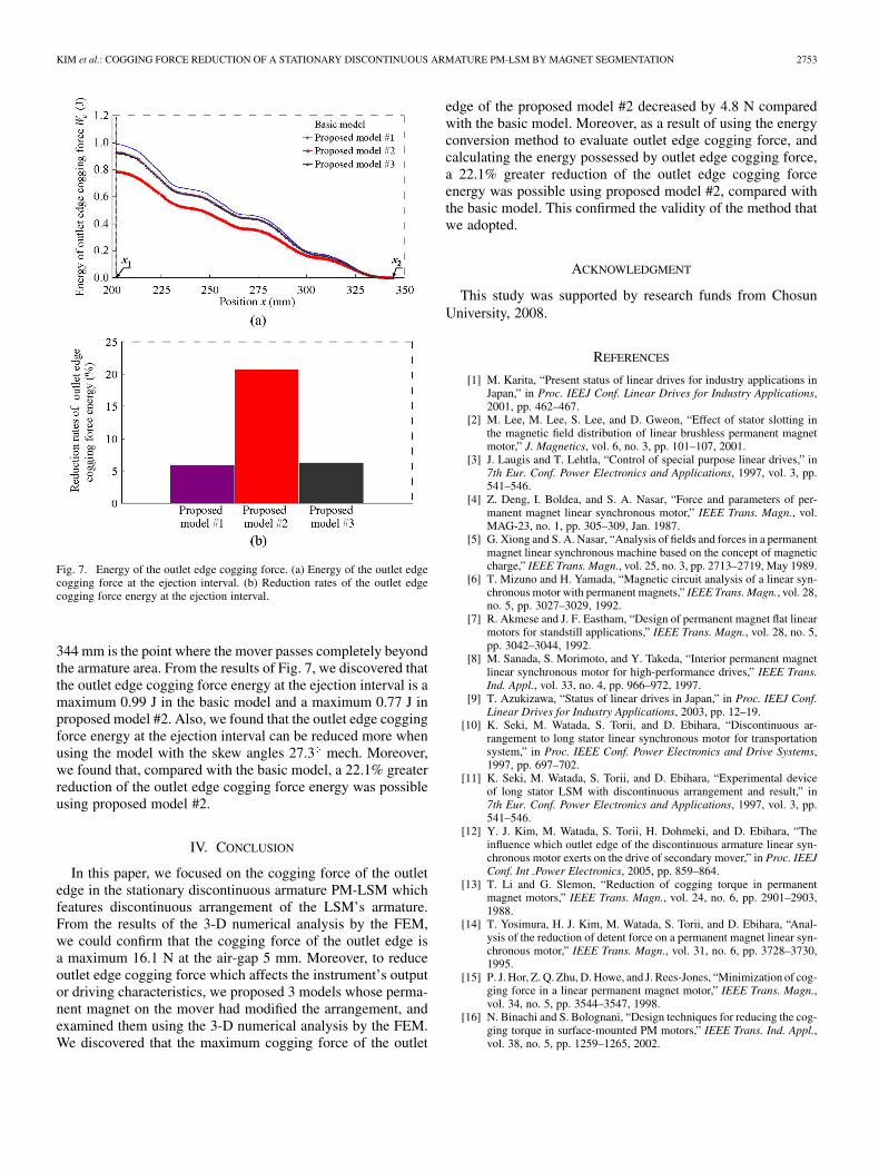
Fig. 7 shows the energy of the outlet edge cogging force atthe ejection interval. Position 202 mm is the point where themover begins to move beyond the armature area and position
KIM et al.: COGGING FORCE REDUCTION OF A STATIONARY DISCONTINUOUS ARMATURE PM-LSM BY MAGNET SEGMENTATION 2753
Fig. 7. Energy of the outlet edge cogging force. (a) Energy of the outlet edgecogging force at the ejection interval. (b) Reduction rates of the outlet edgecogging force energy at the ejection interval.
344 mm is the point where the mover passes completely beyondthe armature area. From the results of Fig. 7, we discovered thatthe outlet edge cogging force energy at the ejection interval is amaximum 0.99 J in the basic model and a maximum 0.77 J inproposed model #2. Also, we found that the outlet edge coggingforce energy at the ejection interval can be reduced more whenusing the model with the skew angles 27.3 mech. Moreover,we found that, compared with the basic model, a 22.1% greaterreduction of the outlet edge cogging force energy was possibleusing proposed model #2.
IV. CONCLUSION
In this paper, we focused on the cogging force of the outletedge in the stationary discontinuous armature PM-LSM whichfeatures discontinuous arrangement of the LSM’s armature.From the results of the 3-D numerical analysis by the FEM,we could confirm that the cogging force of the outlet edge isa maximum 16.1 N at the air-gap 5 mm. Moreover, to reduceoutlet edge cogging force which affects the instrument’s outputor driving characteristics, we proposed 3 models whose perma-nent magnet on the mover had modified the arrangement, andexamined them using the 3-D numerical analysis by the FEM.We discovered that the maximum cogging force of the outlet
edge of the proposed model #2 decreased by 4.8 N comparedwith the basic model. Moreover, as a result of using the energyconversion method to evaluate outlet edge cogging force, andcalculating the energy possessed by outlet edge cogging force,a 22.1% greater reduction of the outlet edge cogging forceenergy was possible using proposed model #2, compared withthe basic model. This confirmed the validity of the method thatwe adopted.
ACKNOWLEDGMENT
This study was supported by research funds from ChosunUniversity, 2008.
REFERENCES
[1] M. Karita, “Present status of linear drives for industry applications inJapan,” in Proc. IEEJ Conf. Linear Drives for Industry Applications,2001, pp. 462–467.
[2] M. Lee, M. Lee, S. Lee, and D. Gweon, “Effect of stator slotting inthe magnetic field distribution of linear brushless permanent magnetmotor,” J. Magnetics, vol. 6, no. 3, pp. 101–107, 2001.
[3] J. Laugis and T. Lehtla, “Control of special purpose linear drives,” in7th Eur. Conf. Power Electronics and Applications, 1997, vol. 3, pp.541–546.
[4] Z. Deng, I. Boldea, and S. A. Nasar, “Force and parameters of per-manent magnet linear synchronous motor,” IEEE Trans. Magn., vol.MAG-23, no. 1, pp. 305–309, Jan. 1987.
[5] G. Xiong and S. A. Nasar, “Analysis of fields and forces in a permanentmagnet linear synchronous machine based on the concept of magneticcharge,” IEEE Trans. Magn., vol. 25, no. 3, pp. 2713–2719, May 1989.
[6] T. Mizuno and H. Yamada, “Magnetic circuit analysis of a linear syn-chronous motor with permanent magnets,” IEEE Trans. Magn., vol. 28,no. 5, pp. 3027–3029, 1992.
[7] R. Akmese and J. F. Eastham, “Design of permanent magnet flat linearmotors for standstill applications,” IEEE Trans. Magn., vol. 28, no. 5,pp. 3042–3044, 1992.
[8] M. Sanada, S. Morimoto, and Y. Takeda, “Interior permanent magnetlinear synchronous motor for high-performance drives,” IEEE Trans.Ind. Appl., vol. 33, no. 4, pp. 966–972, 1997.
[9] T. Azukizawa, “Status of linear drives in Japan,” in Proc. IEEJ Conf.Linear Drives for Industry Applications, 2003, pp. 12–19.
[10] K. Seki, M. Watada, S. Torii, and D. Ebihara, “Discontinuous ar-rangement to long stator linear synchronous motor for transportationsystem,” in Proc. IEEE Conf. Power Electronics and Drive Systems,1997, pp. 697–702.
[11] K. Seki, M. Watada, S. Torii, and D. Ebihara, “Experimental deviceof long stator LSM with discontinuous arrangement and result,” in7th Eur. Conf. Power Electronics and Applications, 1997, vol. 3, pp.541–546.
[12] Y. J. Kim, M. Watada, S. Torii, H. Dohmeki, and D. Ebihara, “Theinfluence which outlet edge of the discontinuous armature linear syn-chronous motor exerts on the drive of secondary mover,” in Proc. IEEJConf. Int .Power Electronics, 2005, pp. 859–864.
[13] T. Li and G. Slemon, “Reduction of cogging torque in permanentmagnet motors,” IEEE Trans. Magn., vol. 24, no. 6, pp. 2901–2903,1988.
[14] T. Yosimura, H. J. Kim, M. Watada, S. Torii, and D. Ebihara, “Anal-ysis of the reduction of detent force on a permanent magnet linear syn-chronous motor,” IEEE Trans. Magn., vol. 31, no. 6, pp. 3728–3730,1995.
[15] P. J. Hor, Z. Q. Zhu, D. Howe, and J. Rees-Jones, “Minimization of cog-ging force in a linear permanent magnet motor,” IEEE Trans. Magn.,vol. 34, no. 5, pp. 3544–3547, 1998.
[16] N. Binachi and S. Bolognani, “Design techniques for reducing the cog-ging torque in surface-mounted PM motors,” IEEE Trans. Ind. Appl.,vol. 38, no. 5, pp. 1259–1265, 2002.