Embed Size (px)
Citation preview

Coated Steel Weldability

Coated Steel Weldability
• Electrode Factors• Coating Factors• Welding Equipment Parameters

Electrode Life
Number of Welds
Dia
mete
r
Electrode Cap Diameter For Coated Steel
Weld Button Diameter For Coated Steel
Weld Button DiameterUncoated Steel
•Electrode Material• Electrode Design

Electrode Life • Electrode Material• Current History• Electrode Design
Steel
Solid Zinc Coating
Molten ZincCopper Alloy Electrode
brass
Melting Point (F)Copper 1980Brass Down to 1710Zinc 787
MeasuredElectrode Face Temp (F)
Bare 1000-1200Galvanized 1500-1700

Cu Zn
~45% ~60% ~85%
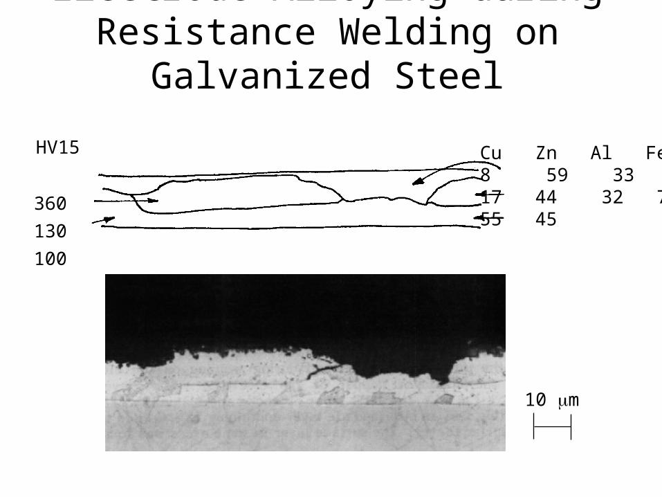
Electrode Alloying during Resistance Welding on Galvanized Steel
10 m
HV15
360
130
100
Cu Zn Al Fe8 59 3317 44 32 755 45

Uncoated
Hot Dipped Galvanized

Electrode Material
Class 1 99 Cu - 1 CdClass 2 99.2 Cu - 0.8 CrZr-Cu 98.9 Cu - 1 Cr - 0.1 ZrDispersion Cu- 2.68% Al2O3
Standard Electrodes
Brazed Tip Electrodes
Mo - called TZM ElectrodeW - results scattered
Flame Sprayed or Coated Electrodes
Mo, W, MoC, WC, Ag, Au, Al2O3

Electrode Materials for Spot Welding Coated Steel
Copper-Chromium-Zirconium (Cu-Cr-Zr) Material
– Higher hardness and softening temperature
– Its conductivity is about the same as Cu-Cr material
– Alloy addition: 0.7 wt% Cr + 0.1 wt% Zr
Copper-Zirconium (Cu-Zr) Material
– Lower hardness than Cu-Cr material
– Higher electrical conductivity (up to 93% IACS)
– Alloy addition: 0.15 wt% Zr
Traditional (Class 2) Copper-Chromium (Cu-Cr) Material• High hardness• Moderate electrical conductivity (about 80% IACS)• Alloy addition: 0.8 wt% Cr
Dispersion-Strengthened Copper (DSC) Material
•Higher electrical conductivity (98% IACS)•A powder metallurgy product

Number of Welds
Ele
ctro
de F
ace
Dia
met
erClass 1
Class 2 Cu-Cr
Al2O3 Flame Spray
Al2O3 Dispersion (Variation in Results)
TZM(Mo Alloy Brazed Cap)
Electrode Material
Cu-Zr

Comparison of ElectrodesN
ug
get S
ize
(inc
h)
Weld Number (Thousands)Z-Trode Cu-Cr Al2O3 DSC
High Current on HDG Steel
Surprising since highhot hardnessCu-Zr

Elec
trod
e Li
fe
DS
C -
AL-
60 E
xcur
sion
s A
bove
Exp
ulsi
on
Cu-
Zr
Cu-
Cr
DSC
AL-
25
DS
C A
L-60
No
Exc
ursi
ons
Excursions Above Expulsion Effect DSC
Gugel, Comparison of Electrode Wear,SMWC V, AWS, 1992
History of Current Excursions

Gugel, Comparison of Electrode Wear,SMWC V, AWS, 1992
The Lower HotHardness of Cu-Cr & Cu-ZrAllow SomeHealing of thePits
In The HarderIn The HarderDSC There Is NoDSC There Is NoSelf Healing.Self Healing.
Excursions Above Excursions Above Expulsion WhereExpulsion WhereElectrodes AreElectrodes AreHotter Allow SomeHotter Allow SomeHealing.Healing.
Deterioration Model
History of Current Excursions

Electrode-Wear Pattern for Flat Electrodes
Flat Electrode
Large Central Cavity
Edges Broken Creating Natural Dome
Craters Forming
Self-Heating + Build-up along Sides
[Reference: Welding in the Automotive Industry, p.174, D. W. Dickinson]
Electrode Design

r > 2 1/2 in.
Zinc BuildupReduced Current DensityPoor Welds
Electrode Design
DomeElectrode
Flattening

Electrode Geometry for Galvanized Steel
1/4” Flat Face x 45° 1/4” Flat Face x 20° 1” Radius Face 3” Radius Face
45°
1/32”Wear
5/16” 27/64” 1/32”Wear
20°
1/2” 1/32”Wear
7/8” 1/32”Wear
1”3”
63% Increasein Area
185% Increasein Area
300% Increasein Area
1100% Increasein Area
Recommendedfor sheet up to
1/16” thick
Recommendedfor sheet over
1/16” thick
Satisfactoryonly when
alignment is aserious problem
Unsatisfactory
Electrode Design

Effect of Cone Angle
Heat Sink
Because of Higher TempMore Copper From Electrode Sticking ToPart
Ikeda et al, Effect of Electrode Configuration…,Adv Tech & Proc, IBEC’94, 1995
Electrode Design

Ikeda et al, Effect of Electrode Configuration…,Adv Tech & Proc, IBEC’94, 1995
Effect of Cone Angle
Faster Face EnlargementLower Current Density
HigherElectrode Temp
BestRange
Electrode Design
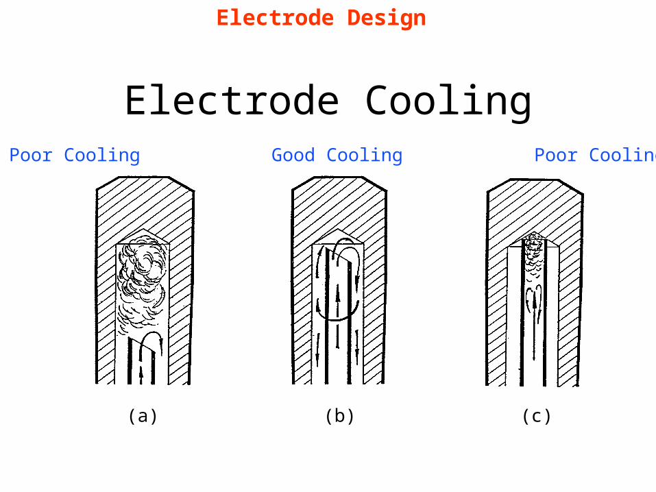
Electrode CoolingPoor Cooling Good Cooling Poor Cooling
(a) (b) (c)
Electrode Design

Process Variables
Process Parameters:
– Weld Current (Heat
Generation)
– Weld Time
– Hold Time
– Electrode Force
– Electrodes
Coating Parameters:
– Coating Thickness
– Coating Types

Resistance
Dis
tanc
eU
ncoa
ted
Coa
ted
Zn has lower R& is soft = goodContact


Weld Diameter vs. Current for Various Coatings
Weld Current, kA
Wel
d D
iam
eter
, in
ches
[Reference: Welding in the Automotive Industry, p.179, D. W. Dickinson]
Current RangeUncoated
UncoatedSteel
30% Fe-Zn27% Ni-Zn
20% Ni-Zn
Zinc Only 9% Fe-Zn
23%Fe-Zn
6 8 10 12 14
0.05
0.10
0.15
0.20
0.25
Current RangeCoated
Nominal CurrentLevel
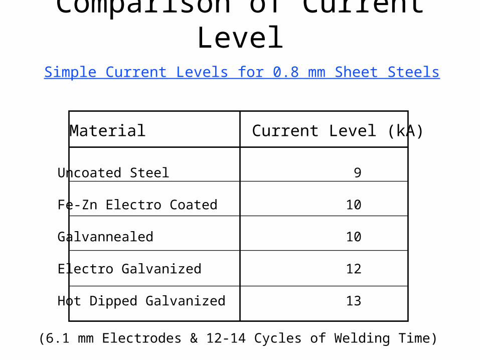
Comparison of Current Level
Material Current Level (kA)
Uncoated Steel 9
Fe-Zn Electro Coated 10
Galvannealed 10
Electro Galvanized 12
Hot Dipped Galvanized 13
Simple Current Levels for 0.8 mm Sheet Steels
(6.1 mm Electrodes & 12-14 Cycles of Welding Time)

Lobe Curves
We
ld T
ime
We
ld T
ime
Weld Current Weld Current
UncoatedHot-DipGalvanized
ZincMelting
Steel Melting

Weld Current vs. Tensile-Shear Strength
Welding Current (Amps, x 103)
Te
nsile
-She
ar
Str
en
gth
(lb
s)
[Reference: Welding in theAutomotive Industry, p.203, D. W. Dickinson]

Electrode Sticking Test
0 550 1100 1850 2200
28
24
20
16
12
8
Number of Welds
We
ldin
g C
urr
ent (
kA) Stick
Expulsion
Nominal
As the number of welds & Electrode
deterioration increase the
current to get a nominal size
weld (or expulsion or
sticking) increases

Shunting during Series Welding
The extra current required to compensate for the shunting causes electrodes to run hotter and results in electrode wear.
AWS Welding Handbook

Process Variables
Process Parameters:
– Weld Current
(Heat Generation)
– Weld Time
– Hold Time
– Electrode Force
Coating Parameters:
– Coating Thickness
– Coating Types

Nugget Development during Weld Time Interval0.041” Bare & Galvanized Steel
Weld Time, cycles
Nu
gge
t Dia
met
er,
inch
es
[Reference: Welding inthe Automotive Industry,p.175, D. W. Dickinson ]

Weld Time vs. Nugget Development
NuggetGrowth
SteelSurface
BreakdownZinc Melts
SurfaceBreakdown
NuggetGrowth
Uncoated Coated
Weld Time
Nu
gge
t Dia
met
er
Nugget Diameterat Expulsion
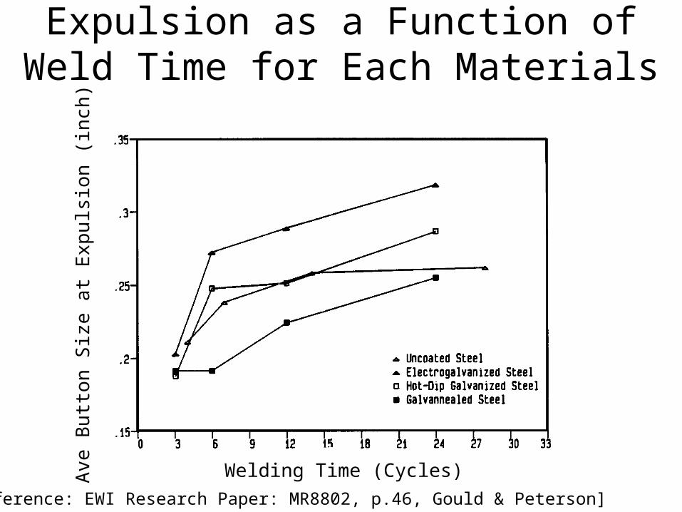
Average Button Size at Expulsion as a Function of Weld Time for Each Materials
[Reference: EWI Research Paper: MR8802, p.46, Gould & Peterson]
Welding Time (Cycles)
Ave
Bu
tton
Siz
e a
t Exp
uls
ion
(in
ch)

Nugget Dimension Vs. Weld TimeN
ugge
t W
idth
(m
m)
Weld Time (Cycles)
[Reference: EWI Research Paper: MR8814, p.29, Gould & Peterson]
Uncoated
Fe-Zn Electro
Galvannealed
Electro-Galvanized
Hot Dipped Galvanized
Effect of Coating Type

Mechanism of Heat Generation
2 Cycles
4 Cycles
5 Cycles
6 Cycles
7 Cycles
9 Cycles
10 Cycles
Step I Step III
Step II Step IV
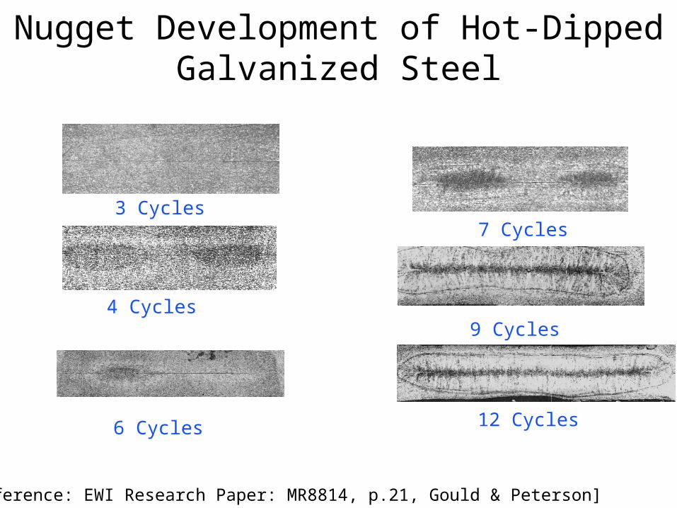
Nugget Development of Hot-Dipped Galvanized Steel
3 Cycles
4 Cycles
6 Cycles
7 Cycles
9 Cycles
12 Cycles
[Reference: EWI Research Paper: MR8814, p.21, Gould & Peterson]

Effect of Weld Time on Current Range for Hot-Dip Galvanized Steel
Welding Current ( kA)
We
ldin
g T
ime
(Cyc
les)
[Reference: EWI Research Paper: MR8802, p.19, Gould & Peterson]
MinimumNominalExpulsion

Effect of Weld Time on Electrode Life
Weld Time
Ele
ctro
de
Life
Longer TimeGreaterAlloying
Short TimeHigh Currentand Overheating
Current

Electrode Life Vs. Welding TimeE
lect
rod
e L
ife (
Nu
mb
er
of W
eld
s) 3200
2400
1600
800
05 9 13 17 21 25 29
Welding Time (Cycles)
Electrode Diameter: 0.19”Electrode Diameter: 0.25”Electrode Diameter: 0.28”

Process Variables
Process Parameters:
– Weld Current
(Heat Generation)
– Weld Time
– Hold Time
– Electrode Force
Coating Parameters:
– Coating Thickness
– Coating Types

No Data Could be FoundOn the Effect of Hold Time
Related to Coating other than That already discussed for
Uncoated High Carbon Steels
This might be an area for research

Process Variables
Process Parameters:
– Weld Current
(Heat Generation)
– Weld Time
– Hold Time
– Electrode Force
Coating Parameters:
– Coating Thickness
– Coating Types
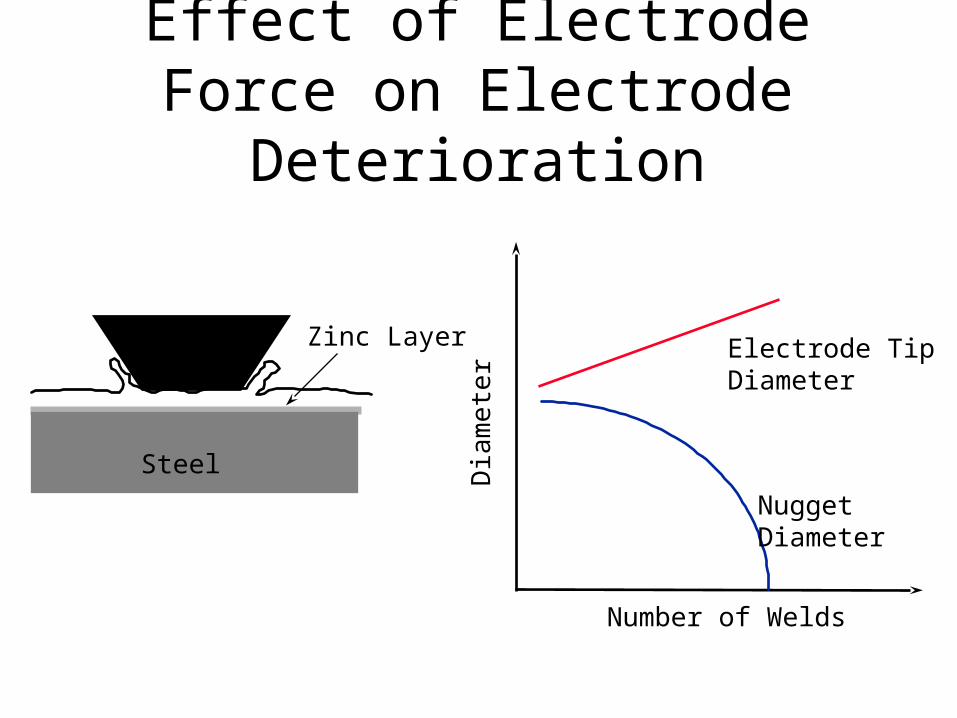
Effect of Electrode Force on Electrode Deterioration
Steel
Zinc Layer Electrode TipDiameter
NuggetDiameter
Dia
me
ter
Number of Welds

Electrode ForceLow High
But
ton
Siz
e A
fter
200
0 W
elds

Dual Force Technique
Time
Cu
rren
tF
orc
e
Low Pressure Electrodes Seat, Zn Forced OutBefore High Pressure, Less Mushrooming
Upslope HelpsZn FlowFrom UnderElectrode

Process Variables
Process Parameters:
– Weld Current
(Heat Generation)
– Weld Time
– Hold Time
– Electrode Force
Coating Parameters:
– Coating Thickness
– Coating Types

Weldability Lobe Vs. Coating Weight(Up To G90 Weight)
Current (kA)
Current (kA)Current (kA)
G40 Weldability Lobe G60 Weldability Lobe
G90 Weldability Lobe
Wel
d T
ime
(C
ycle
s)
Wel
d T
ime
(C
ycle
s)
Wel
d T
ime
(C
ycle
s)
Coating Thickness Only Minimal
Effect on Position or Width
Thicker Coating more
Erratic

Coating Weight Above G90
G90
Welding Parameters Needed to get 0.20” Diameter Weld
Improved ElectrodeLife
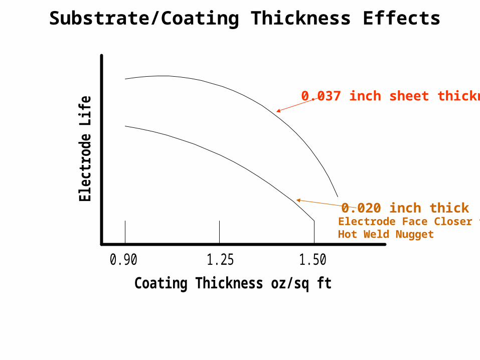
Substrate/Coating Thickness Effects
0.90 1.25 1.50
Coating Thickness oz/sq ft
Ele
ctro
de L
ife0.037 inch sheet thickness
0.020 inch thickElectrode Face Closer to Hot Weld Nugget

Process Variables
Process Parameters:
– Weld Current
(Heat Generation)
– Weld Time
– Hold Time
– Electrode Force

Coating Parameters:
• Coating Thickness
• Coating Types

Elec
trode
Life
elec
troly
tic
hot
galv
anne
aled
dipp
ed
IncompleteIncompleteGalvannealedGalvannealed

SteelAluminum Oxide Passive Layer
Zinc
Gamma
0.1 0.3 1.0% Al in Bath
ElectrodeLife
Incomplete Oxide Layer
Hot Dipped GalvanizedHot Dipped Galvanized
High Si, Mn, Al in SteelTies up OxygenAlso Causing Break in Passive Layer

ZetaZeta
Delta
Gamma
Alpha Alpha SteelSteel
Possible Phases in Galvannealed

Steel
GammaDeltaZeta
Steel
GammaZinc
PartiallyPartiallyGalvannealedGalvannealed
Localized Hot SpotsZinc Alloying in ElectrodeElectrode Life Reduced
Dross
UncleanUncleanCoatingCoating

Steel
GammaDeltaZeta
Pickett, Effect of Total Iron Content….SMAW V, AWS, 1992

Seam Welding Galvanized Steel
Usually not recommended
• Zinc Contamination of Wheel Electrodes• Some outer surface of sheet cracking
Wheels with continuous cleaning have helped
Foil Butt Welding has also been effective (see next Slide)

Foil Butt Welding of Galvanized Steel
AWS Welding Handbook

Projection Welding of Galvanized Steel
AWS Welding Handbook

Projection Welding of Galvanized Steel
• Heat Loss to Electrode (Flat Face) Higher than Uncoated because Higher Thermal Conduction of Coating • Contact Resistance at Faying Surface Only Slightly Lower than uncoated because soft zinc deformation
Therefore: Somewhat lower electrode forces recommended

Projection Welding of Galvanized Steel
•On sheet thinner than 0.09 in. projection welding produces a forged bond rather than a fusion bond• Increase in current causes burn off and expulsion of projection.


![Weldability of Grade 23[1]](https://img.pdfslide.us/doc/110x75/577cd3bb1a28ab9e78976db3/weldability-of-grade-231.jpg)