Embed Size (px)
Citation preview
Welding Inspector
Weldability Of Steels
Section 21
4/23/2007 600 of 691
Weldability of SteelsDefinition
It relates to the ability of the metal (or alloy) to be welded with mechanical soundness by most of the common welding processes, and the resulting welded joint retain the properties for which it has been designed.
is a function of many inter-related factors but these may be summarised as:
•Composition of parent material
•Joint design and size
•Process and technique
•Access
4/23/2007 601 of 691
Weldability of Steels
The weldability of steel is mainly dependant on carbon & other alloying elements content.
If a material has limited weldability, we need to take special measures to ensure the maintenance of the properties required
Poor weldability normally results in the occurrence of cracking
A steel is considered to have poor weldability when:
• an acceptable joint can only be made by using very narrow range of welding conditions
• great precautions to avoid cracking are essential (e.g., high pre-heat etc)
4/23/2007 602 of 691
The Effect of Alloying on SteelsElements may be added to steels to produce the properties required to make it useful for an application.
Most elements can have many effects on the properties of steels.
Other factors which affect material properties are:
•The temperature reached before and during welding
•Heat input
•The cooling rate after welding and or PWHT
4/23/2007 603 of 691
Steel Alloying Elements
4/23/2007 604 of 691
Iron (Fe): Main steel constituent. On its own, is relatively soft, ductile, with low
strength.
Carbon (C): Major alloying element in steels, a strengthening element with
major influence on HAZ hardness. Decreases weldability.
•typically < ~ 0.25%
Manganese (Mn): Secondary only to carbon for strength, toughness and
ductility, secondary de-oxidiser and also reacts with sulphur to form
manganese sulphide.
< ~0.8% is residual from steel de-oxidation
•up to ~1.6% (in C-Mn steels) improves strength & toughness
Silicon (Si): Residual element from steel de-oxidation.
•typically to ~0.35%
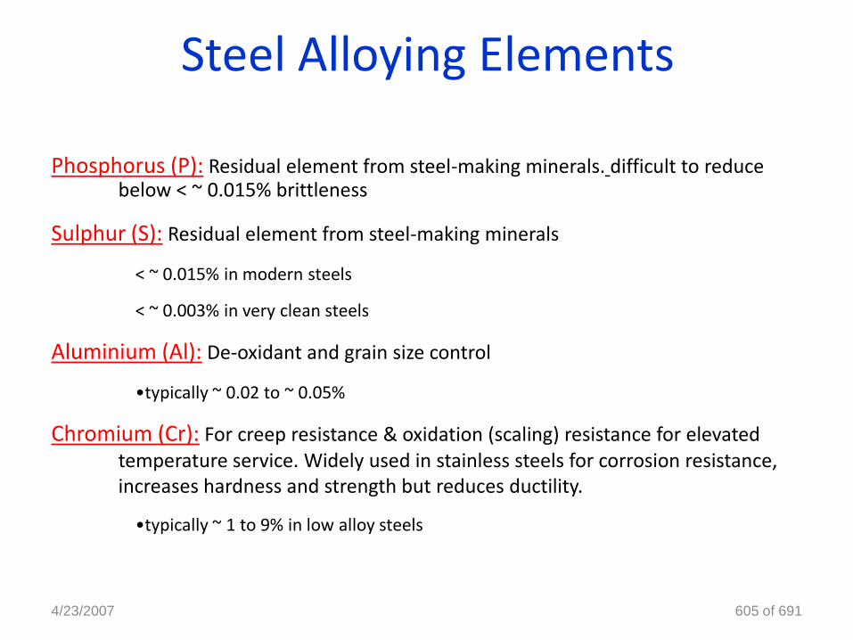
Steel Alloying Elements
Phosphorus (P): Residual element from steel-making minerals. difficult to reduce below < ~ 0.015% brittleness
Sulphur (S): Residual element from steel-making minerals
< ~ 0.015% in modern steels
< ~ 0.003% in very clean steels
Aluminium (Al): De-oxidant and grain size control
•typically ~ 0.02 to ~ 0.05%
Chromium (Cr): For creep resistance & oxidation (scaling) resistance for elevated temperature service. Widely used in stainless steels for corrosion resistance, increases hardness and strength but reduces ductility.
•typically ~ 1 to 9% in low alloy steels
4/23/2007 605 of 691

Nickel (Ni): Used in stainless steels, high resistance to corrosion from acids, increases strength and toughness
Molybdenum (Mo): Affects hardenability. Steels containing molybdenum are less susceptible to temper brittleness than other alloy steels. Increases the high temperature tensile and creep strengths of steel. typically ~ 0.5 to 1.0%
Niobium (Nb): a grain refiner, typically~ 0.05%
Vanadium (V): a grain refiner, typically ~ 0.05%
Titanium (Ti): a grain refiner, typically ~ 0.05%
Copper (Cu): present as a residual, (typically < ~ 0.30%) added to ‘weathering steels’ (~ 0.6%) to give better resistance to atmospheric corrosion
4/23/2007 606 of 691
Steel Alloying Elements
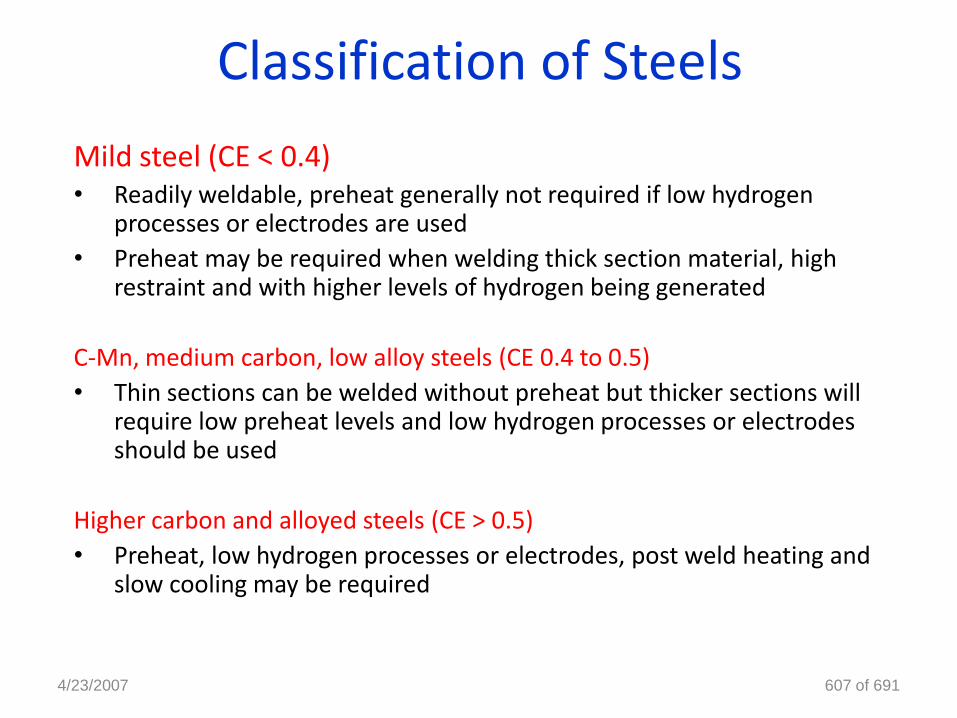
Classification of Steels
Mild steel (CE < 0.4)• Readily weldable, preheat generally not required if low hydrogen
processes or electrodes are used
• Preheat may be required when welding thick section material, highrestraint and with higher levels of hydrogen being generated
C-Mn, medium carbon, low alloy steels (CE 0.4 to 0.5)
• Thin sections can be welded without preheat but thicker sections willrequire low preheat levels and low hydrogen processes or electrodesshould be used
Higher carbon and alloyed steels (CE > 0.5)
• Preheat, low hydrogen processes or electrodes, post weld heating andslow cooling may be required
4/23/2007 607 of 691
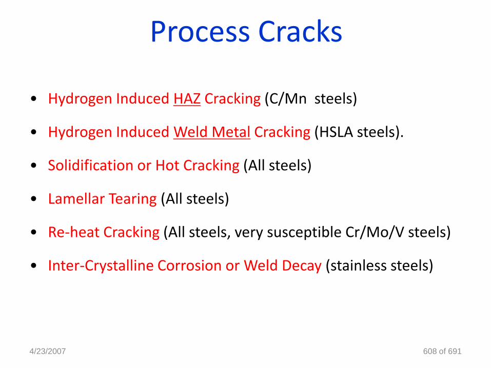
Process Cracks
• Hydrogen Induced HAZ Cracking (C/Mn steels)
• Hydrogen Induced Weld Metal Cracking (HSLA steels).
• Solidification or Hot Cracking (All steels)
• Lamellar Tearing (All steels)
• Re-heat Cracking (All steels, very susceptible Cr/Mo/V steels)
• Inter-Crystalline Corrosion or Weld Decay (stainless steels)
4/23/2007 608 of 691
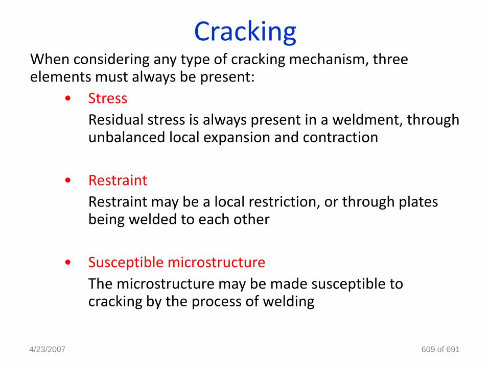
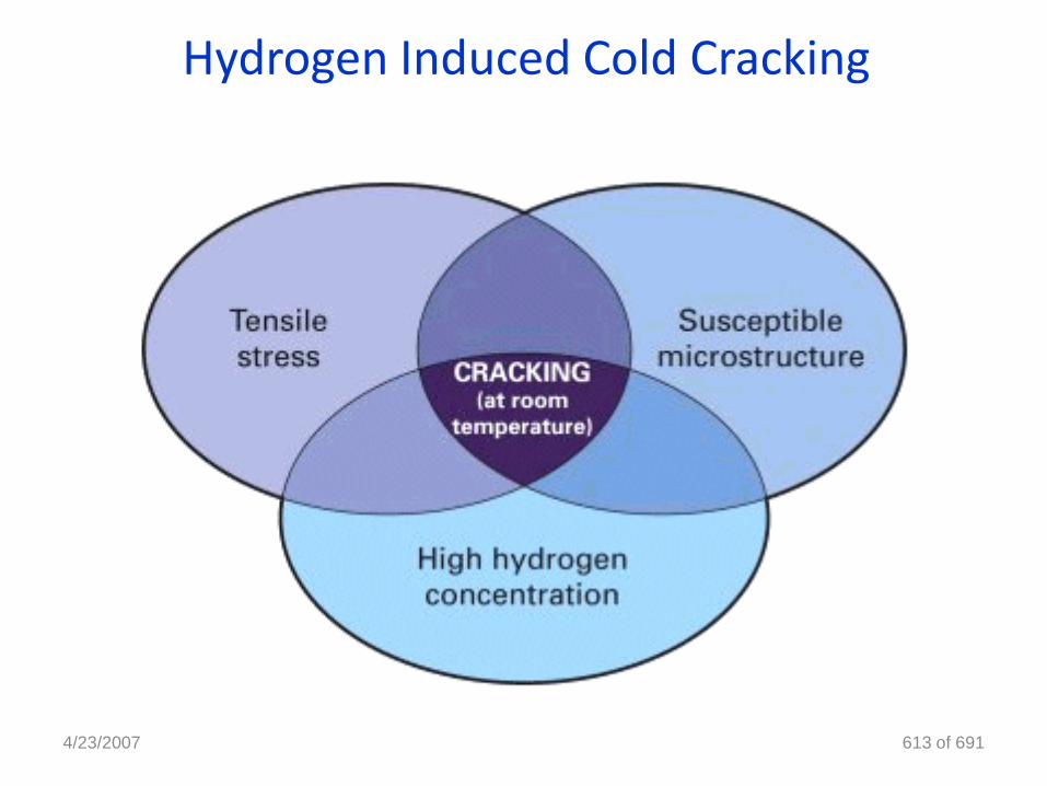
CrackingWhen considering any type of cracking mechanism, three elements must always be present:
• Stress
Residual stress is always present in a weldment, throughunbalanced local expansion and contraction
• Restraint
Restraint may be a local restriction, or through platesbeing welded to each other
• Susceptible microstructure
The microstructure may be made susceptible tocracking by the process of welding
4/23/2007 609 of 691
Cracks
Hydrogen Induced Cold Cracking
4/23/2007 610 of 691
Hydrogen Induced Cold Cracking
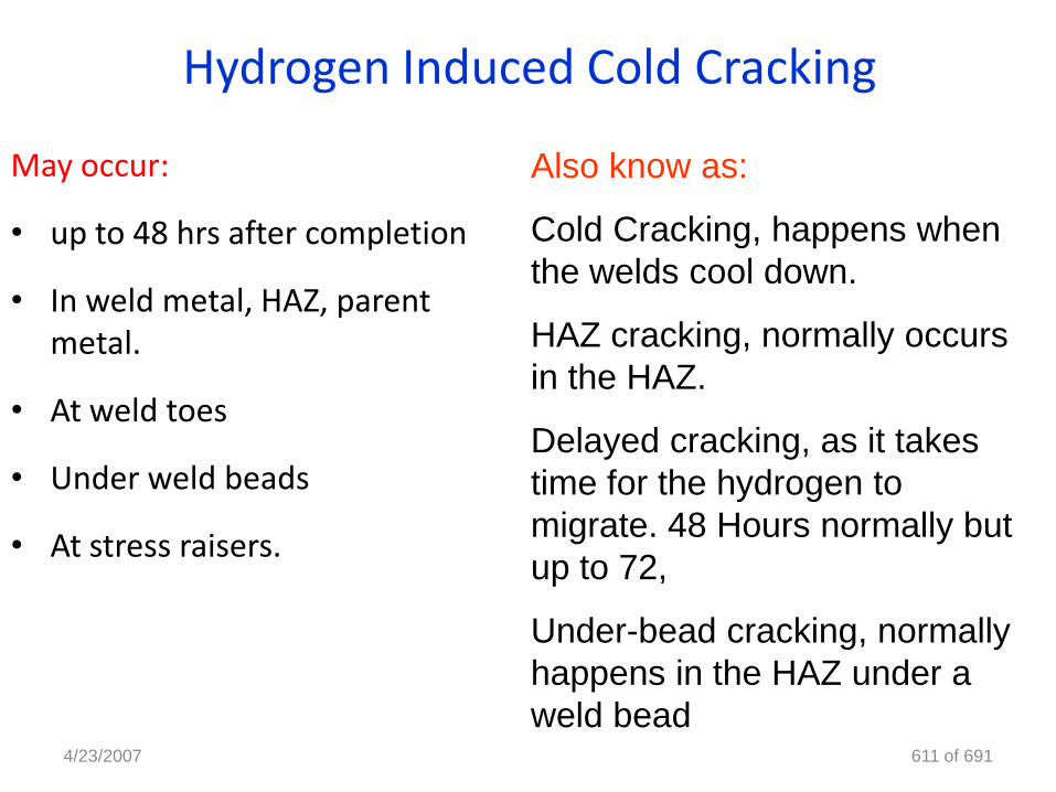
May occur:
• up to 48 hrs after completion
• In weld metal, HAZ, parentmetal.
• At weld toes
• Under weld beads
• At stress raisers.
4/23/2007 611 of 691
Also know as:
Cold Cracking, happens when
the welds cool down.
HAZ cracking, normally occurs
in the HAZ.
Delayed cracking, as it takes
time for the hydrogen to
migrate. 48 Hours normally but
up to 72,
Under-bead cracking, normally
happens in the HAZ under a
weld bead
Hydrogen Induced Cold Cracking
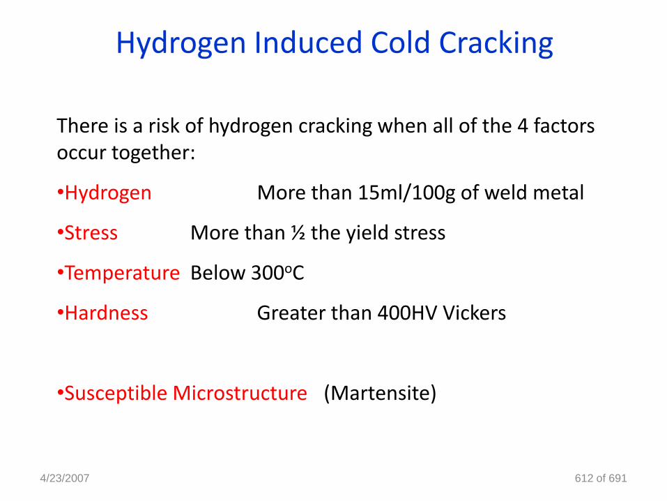
There is a risk of hydrogen cracking when all of the 4 factors occur together:
•Hydrogen More than 15ml/100g of weld metal
•Stress More than ½ the yield stress
•Temperature Below 300oC
•Hardness Greater than 400HV Vickers
•Susceptible Microstructure (Martensite)
4/23/2007 612 of 691
Hydrogen Induced Cold Cracking
4/23/2007 613 of 691
Hydrogen Induced Cold Cracking
Precautions for controlling hydrogen cracking
• Pre heat, removes moisture from the joint preparations, and slows down the cooling rate
• Ensure joint preparations are clean and free from contamination
• The use of a low hydrogen welding process and correct arc length
• Ensure all welding is carried out is carried out under controlled environmental conditions
• Ensure good fit-up as to reduced stress
• The use of a PWHT
• Avoid poor weld profiles4/23/2007 614 of 691
Hydrogen Induced Cold Cracking
4/23/2007 615 of 691
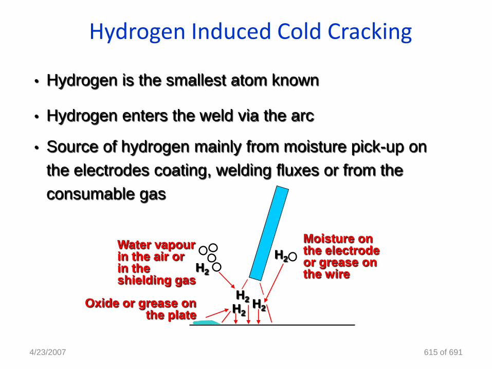
• Hydrogen is the smallest atom known
• Hydrogen enters the weld via the arc
• Source of hydrogen mainly from moisture pick-up on
the electrodes coating, welding fluxes or from the
consumable gas
H2
H2
H2
H2H2
Moisture on the electrode or grease on the wire
Water vapour in the air or in the shielding gas
Oxide or grease on the plate
4/23/2007 616 of 691
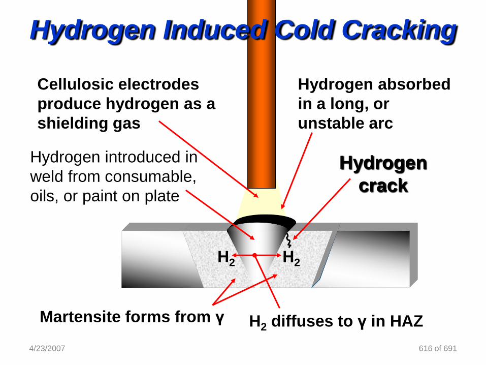
Hydrogen absorbed
in a long, or
unstable arc
Hydrogen introduced in
weld from consumable,
oils, or paint on plate
Cellulosic electrodes
produce hydrogen as a
shielding gas
Hydrogen
crack
Martensite forms from γ H2 diffuses to γ in HAZ
H2H2
Hydrogen Induced Cold Cracking
Hydrogen Induced Cold Cracking
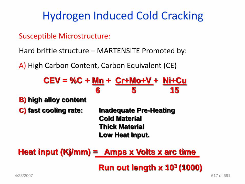
Susceptible Microstructure:
Hard brittle structure – MARTENSITE Promoted by:
A) High Carbon Content, Carbon Equivalent (CE)
4/23/2007 617 of 691
Heat input (Kj/mm) = Amps x Volts x arc time
Run out length x 103 (1000)
CEV = %C + Mn + Cr+Mo+V + Ni+Cu
6 5 15B) high alloy content
C) fast cooling rate: Inadequate Pre-Heating
Cold Material
Thick Material
Low Heat Input.
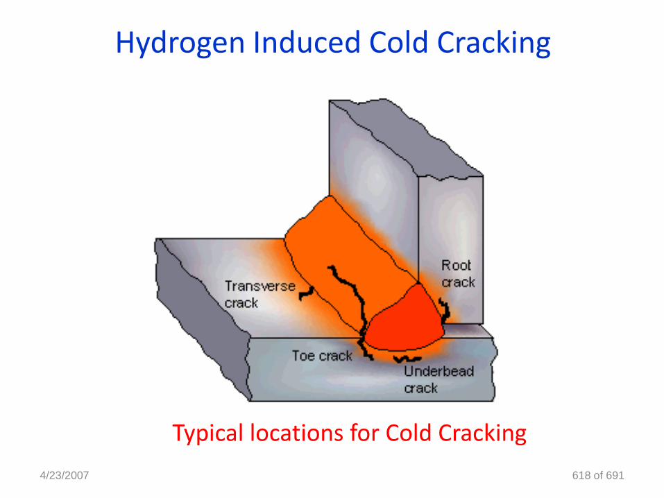
Hydrogen Induced Cold Cracking
Typical locations for Cold Cracking
4/23/2007 618 of 691
4/23/2007 619 of 691
•HSLA or Micro-Alloyed Steels are high strength steels
(800MPa/N/mm2) that derive their high strength from small
percentage alloying (over-alloyed Weld metal to match the
strength of parent metal)
•Typically the level of alloying is in the elements such as
vanadium molybdenum and titanium, nickel and chromium
Strength. are used. It would be impossible to match this micro
alloying in the electrode due to the effect of losses across an
electric arc (Ti burn in the arc)
•It is however important to match the strength of the weld to
the strength of the plate, Mn 1.6 Cr Ni Mo
HICC in HSLA steels
Hydrogen Scales
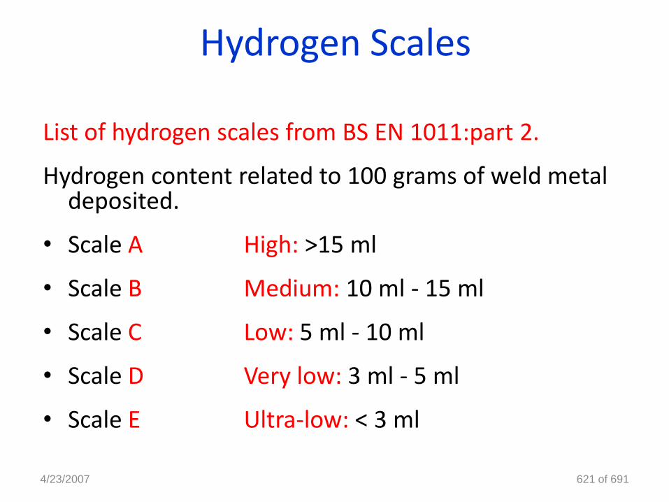
List of hydrogen scales from BS EN 1011:part 2.
Hydrogen content related to 100 grams of weld metal deposited.
• Scale A High: >15 ml
• Scale B Medium: 10 ml - 15 ml
• Scale C Low: 5 ml - 10 ml
• Scale D Very low: 3 ml - 5 ml
• Scale E Ultra-low: < 3 ml
4/23/2007 621 of 691
Potential Hydrogen Level Processes
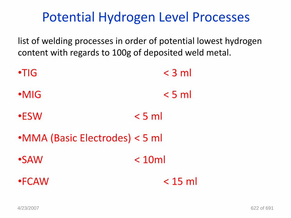
list of welding processes in order of potential lowest hydrogen content with regards to 100g of deposited weld metal.
•TIG < 3 ml
•MIG < 5 ml
•ESW < 5 ml
•MMA (Basic Electrodes) < 5 ml
•SAW < 10ml
•FCAW < 15 ml
4/23/2007 622 of 691
Weldability
Solidification Cracking
4/23/2007 623 of 691
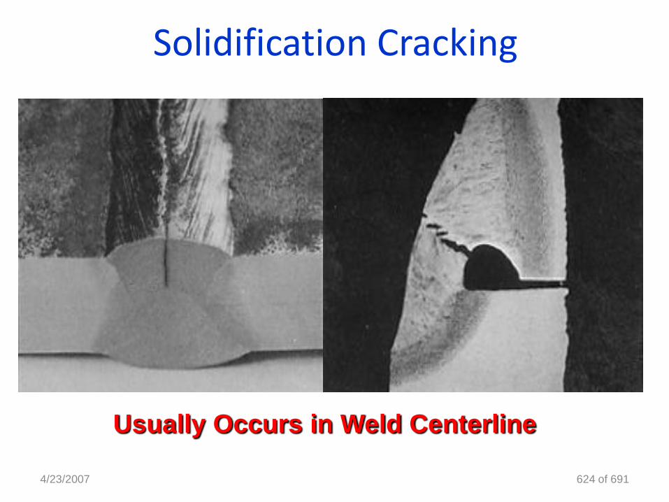
Solidification Cracking
4/23/2007 624 of 691
Usually Occurs in Weld Centerline
Solidification CrackingAlso referred as
Hot Cracking: Occurring at high temperatures while the weld is hot
Centerline cracking: cracks appear down the centre line of the bead.
Crater cracking: Small cracks in weld centers are solidification cracks
Crack type: Solidification cracking
Location: Weld centreline (longitudinal)
Steel types: High sulphur & phosphor concentration in steels.
Susceptible Microstructure: Columnar grains In direction of solidification
4/23/2007 625 of 691
Solidification Cracking
4/23/2007 626 of 691
Factors for solidification cracking
• Columnar grain growth with impurities in weld metal (sulphur,
phosphor and carbon)
• The amount of stress/restraint
• Joint design high depth to width ratios
Liquid iron sulphides are formed around solidifying grains.
High contractional strains are present
High dilution processes are being used.
There is a high carbon content in the weld metal
• Most commonly occurring in sub-arc welded joints
Solidification Cracking
• Sulphur in the parent material may dilute in the weldmetal to form iron sulphides (low strength, low meltingpoint compounds)
• During weld metal solidification, columnar crystals pushstill liquid iron sulphides in front to the last place ofsolidification, weld centerline.
• The bonding between the grains which are themselvesunder great stress and may now be very poor to maintaincohesion and a crack will result, weld centerline.
4/23/2007 627 of 691
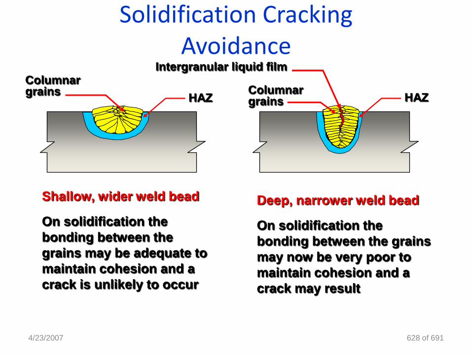
Solidification CrackingAvoidance
4/23/2007 628 of 691
Deep, narrower weld bead
On solidification the
bonding between the grains
may now be very poor to
maintain cohesion and a
crack may result
Shallow, wider weld bead
On solidification the
bonding between the
grains may be adequate to
maintain cohesion and a
crack is unlikely to occur
HAZ HAZ
Intergranular liquid filmColumnar grains Columnar
grains
Solidification Cracking
4/23/2007 629 of 691
Precautions for controlling solidification cracking
•The first steps in eliminating this problem would be to choose a low
dilution process, and change the joint design
Grind and seal in any lamination and avoid further dilution????
Add Manganese to the electrode to form spherical Mn/S which form
between the grain and maintain grain cohesion
As carbon increases the Mn/S ratio required increases
exponentially and is a major factor. Carbon content % should be a
minimised by careful control in electrode and dilution
Limit the heat input, hence low contraction, & minimise restraint
Solidification Cracking
Precautions for controlling solidification cracking
• The use of high manganese and low carbon content fillers
• Minimise the amount of stress / restraint acting on the joint during welding
• The use of high quality parent materials, low levels of impurities (Phosphor & sulphur)
• Clean joint preparations contaminants (oil, grease, paints and any other sulphur containing product)
• Joint design selection depth to width ratios
4/23/2007 630 of 691
Solidification Cracking
Solidification cracking in Austenitic Stainless Steel
• particularly prone to solidification cracking
• large grain size gives rise to a reduction in grain boundary area withhigh concentration of impurities
• Austenitic structure very intolerant to contaminants (sulphur,phosphorous and other impurities).
• High coefficient of thermal expansion /Low coefficient of thermalconductivity, with high resultant residual stress
• same precautions against cracking as for plain carbon steels with extraemphasis on thorough cleaning and high dilution controls.
4/23/2007 631 of 691
Cracks
Lamellar Tearing
4/23/2007 632 of 691
Lamellar Tearing
Factors for lamellar tearing to occur
Cracks only occur in the rolled plate !
Close to or just outside the HAZ !
Cracks lay parallel to the plate surface and the fusion boundary of the weld and has a stepped aspect.
• Low quality parent materials, high levels of impurities
• Joint design, direction of stress
• The amount of stress acting across the joint during welding
• Note: very susceptible joints may form lamellar tearing under very low levels of stress
4/23/2007 633 of 691
Lamellar Tearing
4/23/2007 634 of 691
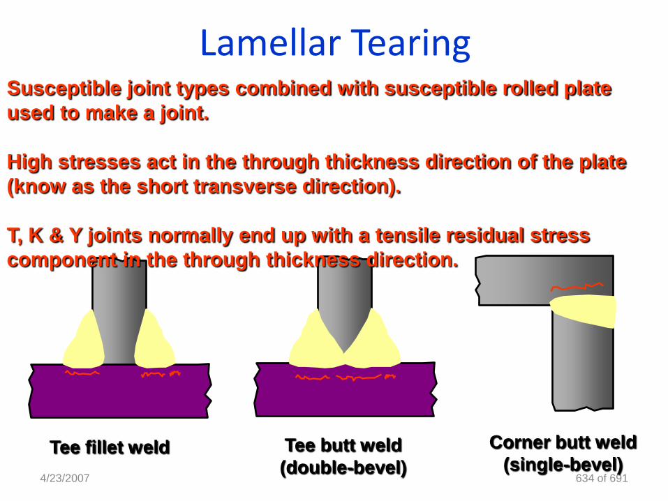
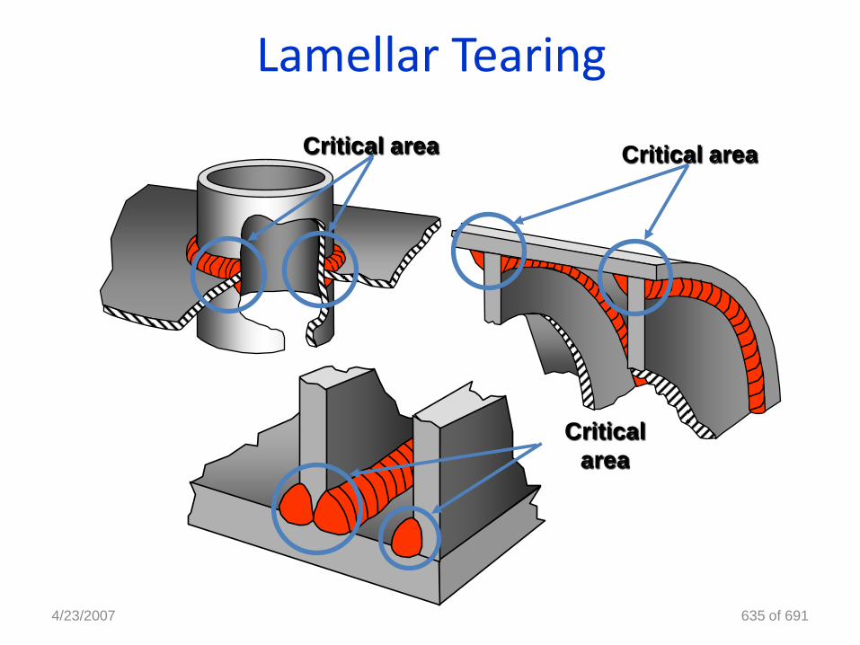
Tee fillet weld Tee butt weld
(double-bevel)
Corner butt weld
(single-bevel)
Susceptible joint types combined with susceptible rolled plate
used to make a joint.
High stresses act in the through thickness direction of the plate
(know as the short transverse direction).
T, K & Y joints normally end up with a tensile residual stress
component in the through thickness direction.
Lamellar Tearing
4/23/2007 635 of 691
Critical area
Critical
area
Critical area
Lamellar Tearing
4/23/2007 636 of 691
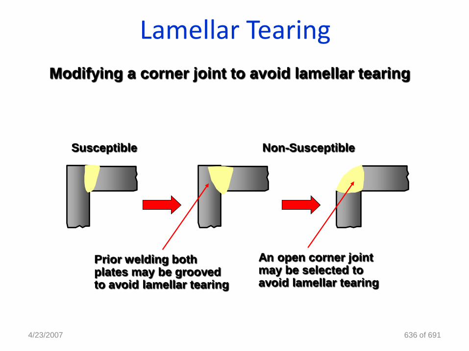
Modifying a corner joint to avoid lamellar tearing
Susceptible Non-Susceptible
Prior welding both plates may be grooved to avoid lamellar tearing
An open corner joint may be selected to avoid lamellar tearing
Lamellar Tearing
4/23/2007 637 of 691
Precautions for controlling lamellar tearing
• The use of high quality parent materials, low levels of
impurities
• The use of buttering runs
• A gap can be left between the horizontal and vertical
members enabling the contraction movement to take
place
• Joint design selection
• Minimise the amount of stress / restraint acting on the
joint during welding
• Hydrogen precautions
Lamellar TearingCrack type: Lamellar tearing
Location: Below weld HAZ
Steel types: High sulphur & phosphorous steels
Microstructure: Lamination & Segregation
4/23/2007 638 of 691
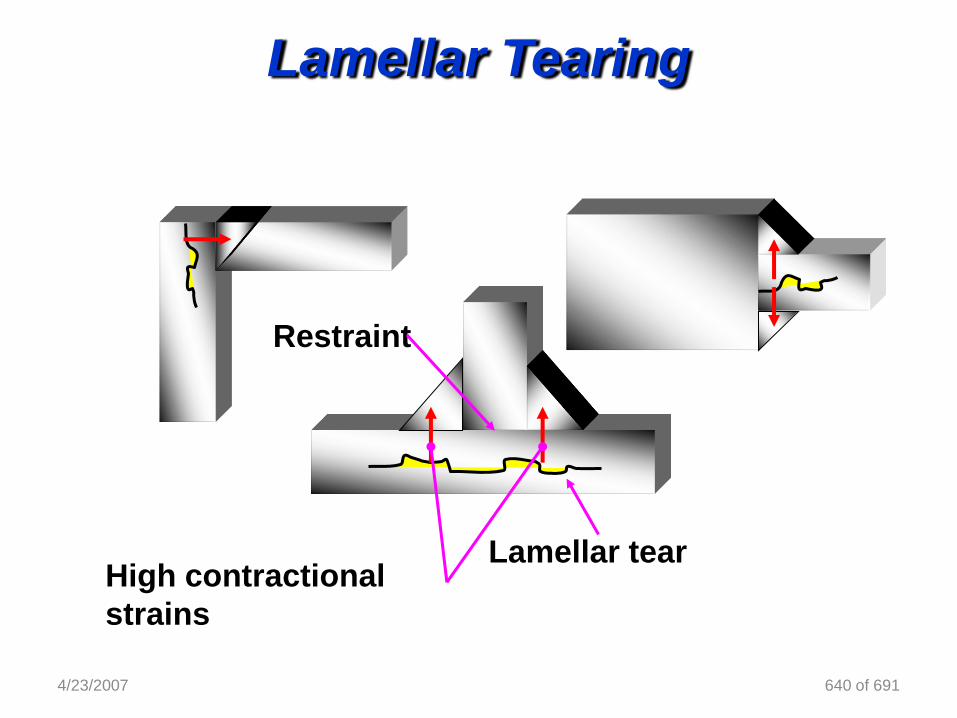
Occurs when:
High contractional strains are through the short
transverse direction. There is a high sulfur content in
the base metal.
There is low through thickness ductility in the base
metal.
There is high restraint on the work
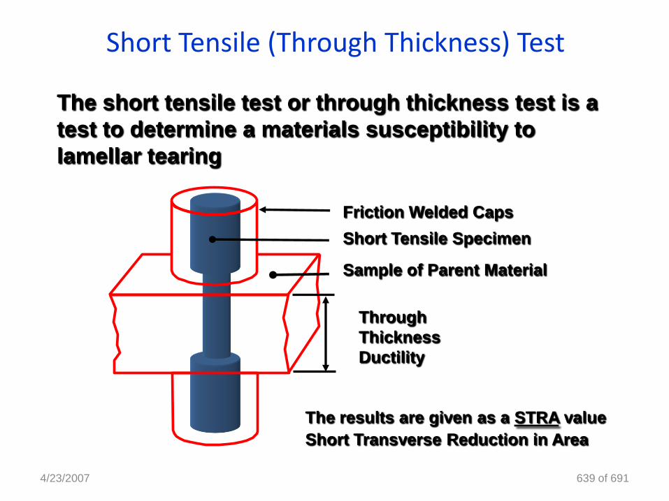
Short Tensile (Through Thickness) Test
4/23/2007 639 of 691
The short tensile test or through thickness test is a
test to determine a materials susceptibility to
lamellar tearing
Friction Welded Caps
Short Tensile Specimen
Through
Thickness
Ductility
Sample of Parent Material
The results are given as a STRA value
Short Transverse Reduction in Area
4/23/2007 640 of 691
High contractional
strains
Lamellar tear
Restraint
Lamellar Tearing