Embed Size (px)
Citation preview

ORIGINAL PAPER
Co-electrodeposition of MnO2/graphene oxide coatingon carbon paper from phosphate buffer and the capacitiveproperties
Hua Zhao & Feifei Liu & Gaoyi Han & Zhaoyang Liu &
Bin Liu & Dongying Fu & Yanping Li & Miaoyu Li
Received: 8 January 2013 /Revised: 15 September 2013 /Accepted: 8 October 2013# Springer-Verlag Berlin Heidelberg 2013
Abstract MnO2/graphene oxide sheet composite (MnO2/GOS) has been co-electrodeposited on the thermally treatedcarbon paper (TTCP) in phosphate buffer solution containingGOS and KMnO4. The resulted samples have beencharacterized by scanning and transmission electronmicroscopy, Raman, X-ray diffraction, and X-rayphotoelectron energy spectroscopy. The results show that thesynthesized MnO2 may be δ-MnO2 and the morphology ofMnO2/GOS is very different from that of MnO2, indicatingthat the introduction of GOS in electrolyte can influence themorphology during the deposition. The capacitive propertiesof the samples are investigated by using cyclic voltammetry,galvanostatic charge/discharge, and electrochemicalimpedance spectroscopy. The specific capacitance of MnO2
for MnO2/GOS can reach about 829 F g−1 at dischargedcurrent density of 1.0 A g−1 in 1 M Na2SO4 aqueous solution,which is larger than that of MnO2 deposited on TTCP. Thecomposite of MnO2/GOS also exhibits excellent cyclicstability with a decrease of 18.5 % specific capacitance after1,500 cycles.
Keywords Graphene oxide .MnO2. Electrodeposition .
Capacitor . Carbonmaterials
Introduction
Electrochemical capacitors, known as a kind of electricalcharge-storage devices, have attracted tremendous attentionbecause of their high power density, excellent reversibility,and cycle life [1, 2]. Based on the operating mechanisms,electrochemical capacitors can be generally classified intotwo kinds: one is the double-layer capacitors which dependon the charge-separation at the interface of the electrode’smaterials and electrolyte; the other is pseudocapacitors whichdepend on the Faradic redox reaction of the electrochemicallyactive materials. Recently most research about the materials ofe l e c t r ode has focused on the deve lopmen t o felectrochemically active materials including various carbonmaterials, conducting polymers, and transition metal oxides[3–6].
Among the electrochemically active materials, manganeseoxide is considered as a promising material due to its low cost,high electrochemical activity and environment-friendly nature[5, 6]. Although MnO2 possesses high specific capacitance(C cs) in theory (1,370 F g−1) [7, 8], the values of Ccs for thesynthesizedMnO2 usually range from 100 to 400 F g−1 [9, 10]because the capacitive reaction ofMnO2 can only occur on thesurface due to its poor conductivity. Therefore, thearchitecture for hybrid electrode has been developed toimprove the performance of electrodes. Thin MnO2 film isusually deposited on high-surface-area conductive supports toincrease its surface area and mass loading, and to improve theconductivity of the material [11, 12].
Up to date, the composites of MnO2 and carbon materialssuch as carbon nanotubes and carbon paper have beensynthesized and measured for their capacitive properties[13–17]. Graphene is regarded as promising material in
Electronic supplementary material The online version of this article(doi:10.1007/s10008-013-2291-0) contains supplementary material,which is available to authorized users.
H. Zhao : F. Liu :G. Han (*) : Z. Liu : B. Liu :D. Fu :Y. Li :M. LiInstitute of Molecular Science, Key Laboratory of Chemical Biologyand Molecular Engineering of Education Ministry, ShanxiUniversity, Taiyuan 030006, Chinae-mail: [email protected]
J Solid State ElectrochemDOI 10.1007/s10008-013-2291-0

consideration of its excellent conductivity, large specificsurface area and good mechanical property [18, 19], so somecomposites of MnO2 and graphene have also been fabricated[20–23], and the results demonstrate that the addition ofgraphene can improve the capacitive performance. Besidesthe precipitation, hydrothermal and sol–gel processes,electrochemical deposition is a convenient method to depositMnO2 on conductive substrates by anodic or cathode processwhen Mn2+ or MnO4
− are used as precursors [6, 24–27].Recently, the composite of MnO2 and graphene has also
been fabricated by electro-depositing MnO2 on the layer ofelectrochemically reduced graphene through anodic process,and the C sc of the composite was reported to be about122 F g−1 [28]. The co-deposition of MnO2 and graphene orGOS through anodic process is difficult because Mn2+ or highconcentration of Na2SO4 will agglomerate the GOS in theaqueous solution. However, in the phosphate buffer solution(PBS), the dispersion of GOS is stable although theconcentration of KMnO4 is relatively high. On the other hand,GOS can be electrochemically reduced to graphene inphosphate buffer solution (PBS) at negative potential [29,30]. Considering the above-mentioned factors, the hybrid ofMnO2/GOS will be co-deposited on thermally treated carbonpapers (TTCP) by using cyclic voltammetry (CV) in PBScontaining KMnO4 and GOS. It is expected that the obtainedproduct exhibits high capacitive performance.
Experiment
The deposition of MnO2/GOS composite on carbon paper
According to literatures [31, 32], GOS was synthesized fromthe powdered flake graphite (325 mesh). The commercialcarbon papers (CP, Toray Composites Inc, Japan) werethermally treated in a muffle furnace at 550 °C under theatmospheric atmosphere for 1 h firstly, and then in a mufflefurnace at 550 °C in air for 3 h again after being heated at 1,200 °C for 2 h in a tube furnace under Ar atmosphere (TTCP).During the process of treatment, the surface of carbon fiberswas activated by oxygen in air at 550 °C firstly, and theformed activated groups were removed at 1,200 °C under Aratmosphere and then more sites were left on the surface afterthe activation again in air at 550 °C [33, 34]. It was expectedthat the carbon fibers exhibit larger surface area and morehydrophilic by this treatment. The reagent of KMnO4 andothers were analytical grade without further purification.
The GOS powder was exfoliated in 0.067 mol L−1 PBS(pH=9.18) under ultrasonic condition to form colloidaldispersion of GOS (1.0 mg mL−1) firstly, then KMnO4 wasdissolved into the dispersion of GOS to form the electrolyte(CKMnO4=3.0 mgmL−1). The strips of TTCP (20 mm×3mm)fixed on the copper bar, Pt plate, and saturated calomel
electrode (SCE) were used as the working, counter, andreference electrodes, respectively. The electro-depositionwas carried out on CHI 660C electrochemical station(Chenhua, Shanghai) by CV method, the potential windowranged from 0.8 to −0.15 Vand the scan rate was 100 mV s−1.The obtained sample was named as TTCP-MnO2/GOS andthe mass loading of MnO2 was about 0.43 mg cm−2 based onthe geometric surface area of the electrode. In order to make acomparison, the sample defined as TTCP-MnO2 was alsoprepared under the same condition but without GOS in theelectrolyte.
Characterization and electrochemical measurements
The morphologies of the samples were observed on a JSM-6701F scanning electron microscope (SEM) operating at10 kV and transmission electron microscopy (TEM, JEOL2010) operating at 200 kV. For measurements of TEM, thesamples deposited on TCCP were peeled in water byultrasonic. The X-ray diffraction (XRD) patterns wererecorded on a Bruker D8 Advance X-ray diffractometer(CuKα) in the 2 theta range of 5°–80° by using grazingincidence accessories. The X-ray photoelectron spectroscopy(XPS) was performed on an American Thermo-VG ScientificESCALAB 250XPS system with Al Kα radiation as theexciting source. Raman spectra were recorded on a JobinYvonLab RAMHR800 microscopic confocal Raman spectrometerby using laser of 514.5 nm as incident light. To have a highsignal-to-noise ratio, each spectrum was the average of 8successive scans, and to avoid sample photodecompositionor denaturation, the spectra were recorded using a lowexcitation power of 10 mW.
The capacitive properties of the electrodes were evaluatedon CHI 660C electrochemical station by using TTCP-MnO2/GOS and TTCP-MnO2 fixed on copper rods, Pt plate, andSCE electrodes as working, counter and reference electrode in1.0 mol L−1 Na2SO4 aqueous solution. The CV curves wererecorded in a potential range of −0.1 to 0.8 V at various scanrates. Charge/discharge curves were recorded at differentcurrent densities with the cutoff voltage between −0.1 and0.8 V. The electrochemical impedance spectra (EIS) weremeasured in the range of 105–10−2 Hz at open-circuit withac-voltage amplitude of 5 mV.
Results and discussion
The characterization of the materials
The CV curves during the process of electro-deposition forMnO2/GOS are shown in Fig. 1a, from the curve of first cycle,it is clear to find that MnO4
− can be reduced at about 0.51 Vand that the reduction current increases with the decrease of
J Solid State Electrochem

potential during the negative scan, while an oxidative waveappears at about 0.40 V during the positive scan, whichindicates that MnO2 has deposited on the surface of TTCP.With the process proceeding, the oxidative waves shift toabout 0.25 Vand the peak current densities increase, revealingthat more amounts of MnO2/GOS has been deposited on thesurface of TTCP. It is surprising to find that the strongdiffraction peak of C (002) appears in the XRD pattern ofTTCP-MnO2/GOS (Fig. 1B—c) but no obvious diffraction
peaks are related to MnO2. However, it can be found carefullythat the TTCP-MnO2/GOS shows a weak broad peak near theC(200) diffraction peak compared with the XRD pattern ofTTCP (Fig. 1B—d). In order to clarify the products, thesynthesized MnO2 and MnO2/GOS hybrid are scraped fromthe electrode and measured. Both the XRD patterns showweak and broad peaks at about 18°–36° (Fig. 1B—a, b),indicating that the synthesized MnO2 exhibits very smallparticles or is amorphous.
Fig. 1 (A) CV depositionprocess of the MnO2/GOS on theTTCP in PBS containing0.5 mg mL−1 GOS. (B) XRDpatterns of MnO2 (a), MnO2/GOS hybrid (b), TTCP-MnO2/GOS (c), and TTCP (d). (C)Mn2p XPS peaks of MnO2/GOShybrid. (D) The C1s XPS peaksof GOS (a) and MnO2/GOShybrid (b). (E) The Ramanspectra of GOS (a), MnO2 (b),and MnO2/GOS (c)
Fig. 2 The micrographs of thesamples, SEM images of TTCP(A), TTCP-MnO2 (B), andTTCP-MnO2/GOS (C). TheTEM images of MnO2 (D) andMnO2/GOS (E). The insertedfigures in SEM images are thelow magnified images, and theinserted figures in TEM imagesare the low magnified images andthe patterns of selected areaelectron diffraction
J Solid State Electrochem

In order to clarify the valence state of Mn, the XPS spectraare recorded and shown in Fig. 1C. From the XPS peaks ofMn2p, it is found that the peaks of Mn2p3/2 and Mn2p1/2 arelocated at about 642.9 and 654.7 eV, the difference betweenthem is about 11.8 eV, indicating that the main productdeposited on the carbon substrates is MnO2 [11]. The C1sXPS spectrum of GOS shows two peaks at 284.5 and287.0 eV which can be assigned to the C–C bond and theoxygen-containing groups such as C–O, COOR, and C=O(Fig. 1D—a), respectively. However, the sample of MnO2/GOS shows weak peaks related to C–C bond and oxygen-containing groups in contrast with GOS [35]. The Ramanspectra of the GOS, MnO2 and MnO2/GOS are shown inFig. 1E. It is found that the GO shows two broad bands(Fig. 1E—a). According to the literature [36], the two bandscan be fitted by four components, the G band (1,598 cm−1) isattributed to all sp2 carbon forms and provides information onthe in-plane vibration of sp2 bonded carbon atoms while the Dband (1,354 cm−1) suggests the presence of sp3 defects [31].The components centered near 1,522 and 1,190 cm−1 arecalled D″ and I bands, respectively, but they have uncertainorigins [36]. The spectrum of the electro-synthesized MnO2
exhibits the peaks at the region of 400–800 cm−1 (Fig. 1E—b),which are attributed to the stretching mode of the MnO6
octahedra [37].The band around 642 cm−1 could be attributedto the symmetric stretching vibration (Mn–O) of the MnO6
groups, while the peak at 572 cm−1 could be due to the Mn–Ostretching in the basal plane of the MnO6 sheet [37].According to the literatures [37, 38], it can be deduced thatthe synthesized MnO2 may be birnessite. However, thesample of MnO2/GOS exhibits the peaks of MnO2 and GOS(Fig. 1E—c), the peaks corresponding to the MnO2 shift tohigh wavenumber slightly, which may be attributed to thepresence of GOS. It is found that the intensity of G band insample of MnO2/GOS become stronger compared with that inGOS, and that the D/G value (the area ratio of D to G band) forMnO2/GOS (1.36) is smaller than that for GOS (2.28),indicating that the defects have become less and the GOSmay be part ial ly reduced during the process ofelectrodeposition. Furthermore, the obvious 2D peak suggeststhat the GOS are separated well by the formed MnO2.Considering that the GO is electrochemically reduced atpotential of −1.0 to 1.5 V and the potential in our experimentis arranged at −0.15 to 0.8 V, so we can deduce that GOS maybe partially reduced during the deposition process accordingto the fact that C1s XPS peak related to the oxygen-containinggroups has become weak and that the value of D/G hasbecome small according to the Raman spectra.
From the images of the micro-morphologies shown inFig. 2, it is found that the surface of the fibers in TTCP isrough and the diameter of the fibers ranges from several tomore than 10 microns (Fig. 2A), and many small holes areobserved on the surface of the fibers. The surface of the fibersin TTCP-MnO2 becomes smooth and the fibers are coated byporous layer of MnO2 formed by small MnO2 particles(Fig. 2B), and the outer and inner fibers are coated with theMnO2 layer (inserted figure). However, the morphology ofTTCP-MnO2/GOS is very different from TTCP-MnO2, theGOS coated with MnO2 agglomerates together to form afluffy layer on the surface of fibers, many gaps or pores aredispersed on the layer of MnO2/GOS (Fig. 2C). The TEMimages show that the MnO2 and MnO2/GOS deposited onTTCP are flakes, and that the MnO2 (Fig. 2D) deposited on
Fig. 3 The plot of specific capacitance of MnO2 versus the concentrationof GO in the electrolyte
Fig. 4 CV curves of TTCP-MnO2/GOS at different scan rates(A), the plots of the specificcapacitance of MnO2 for TTCP-MnO2 (a) and TTCP-MnO2/GOS(b) versus the scan rates (B)
J Solid State Electrochem
TTCP exhibits denser structure than MnO2/GOS (Fig. 2E).The magnified image of MnO2/GOS shows that distancebetween the GOS layers is about 0.35 nm (SFig. 1). It is foundthat two diffraction rings are appeared in the patterns ofselected area electron diffraction for MnO2 and MnO2/GOS.It can be calculated that the distances between the planes areabout 0.143 and 0.252 nm, which can be corresponded to the(020) and (200) planes in δ-MnO2.
Figure 3 shows the relationship between the values of Ccs
of MnO2 and concentrations of GOS in the electrolyte. It isfound that the value of C cs for MnO2 increases with theincrease of GOS concentration and reaches the maximumand keeps a plateau when the concentration of GOS rangesfrom 0.5 to 1.5 mg mL−1. The MnO2/GOS obtained by thismethod possesses relatively higher values of Ccs than that ofMnO2 at the optimum conditions, which may be attributed tothe high dispersion of MnO2 on GOS and the porous structureformed on the TTCP. On the other hand, it is well known thatGOS will agglomerate in the presence other reagents such assalts or when its concentration is high. The high content ofGOS will aggregate and make the surface area decreased andcause the size of MnO2 particles large [39]. Therefore, theGOS will facilitate the dispersion of in the optimumconcentrations, and the PBS containing 1.0 mg mL−1 GOS
and 3.0 mg mL−1 KMnO4 is chosen as electrolyte in thefollowing experiments.
The electrochemical properties
The CV curves of TTCP-MnO2/GOS at various scan rates areshown in Fig. 4A, it is found that the CV curves do not showobvious redox peaks corresponding to MnO2 in the wholevoltage range, indicating that the electrode is charged ordischarged at a pseudo-constant rate during the whole CVprocess. The shapes of the curves are rectangular-like withthe almost symmetric I–E responses when the scan rates arelower than 100 mV s−1, indicating that there is the rapidcurrent response on voltage reversal at each end potential,which accords with the ideal capacitive behavior. The shapesof CV curves for TTCP-MnO2 are similar to that for TTCP-Mn/GOS, but exhibit small current density at the same scanrates (Fig. S2). According to the literature [40], the Ccs ofMnO2 in TTCP-Mn/GOS and TTCP-MnO2 (Fig.S2) can becalculated and found to be about 741 and 611 F g−1,respectively. The Ccs of MnO2 decreases gradually with theincrement of the scan rate, but the values of Ccs for TTCP-MnO2/GOS are larger than that for TTCP-MnO2 at all scanrates (Fig. 4B). For example at 100 mV s−1, TTCP-MnO2/GOS retains a C cs of about 434 F g−1 (59 % of the initial Ccs)while TTCP-MnO2 retains a C cs of about 353 F g−1 (57 % ofthe initial Ccs).
From the discharged curves of TTCP-MnO2/GOS atvarious current densities (Fig. 5A), it can be found that theCcs for MnO2 can reach to about 829 F g−1 at the dischargedcurrent density of 1 A g−1, and that the discharged timedecreases with the increment of the discharged current density.Furthermore, it is found that the discharged curves are almostlinear at large current density while non-linear at small currentdensity. It is well known that the capacitance of MnO2
contains the electric double layer capacitance and Faradiccapacitance. At large current density, the electric double layercapacitance is primary and the discharged curve is linear;
Fig. 5 The discharged curves ofTTCP-MnO2/GOS at variouscurrent densities (A) and thecycling charge/discharge curves(B) for TTCP-MnO2/GOS (a)and TTCP-MnO2 (b) at thecurrent density of 5 A g−1
Fig. 6 The plots of the specific capacitance of MnO2 versus the cyclenumbers for TTCP-MnO2 (a) and TTCP-MnO2/GOS (b)
J Solid State Electrochem

however, the Faradic capacitance will become important at thesmall current density. Therefore, the non-linear curveobserved for 1.0 A g−1 can be attributed to the reduction ofthe material at low potential. The Ccs for MnO2 deposited onTTCP (TTCP-MnO2) is calculated to be 749 F g−1 accordingto the discharged curve shown in Fig. S3. From the repeatedcharge/discharge curves at 5.0 A g−1 (Fig. 5B), it is also foundthat the charged curves are almost symmetric to theirdischarged counterparts in the whole potential region.Furthermore, the sample of TTCP-MnO2/GOS shows a longercharge/discharge time and less deviation from cutoff potentialthan that of TTCP-MnO2. This may be that the contactbetween the active material and TTCP becomes loosen dueto the volume change of MnO2 caused by the ions insertionand deinsertion during the repeated charge/discharge process.However, the large porous structure makes TTCP-MnO2/GOS avoided this defect. These results indicate that TTCP-MnO2/GOS not only exhibits higher Ccs but also higherstability compared with TTCP-MnO2.
The EIS spectra (Fig.S4) show the small arc in the high-frequency region and almost linear portion at low-frequencyregion. The impedance spectra are analyzed by the software ofZView2 on the basis of the electrical equivalent circuit asshown in Fig.S4A. In the low-frequency region, the spike isalmost vertical, indicating a pronounced capacitive behaviorwith small diffusion resistance. At very high frequency, theintercept on real axis represents a combined resistance (R s)including intrinsic resistance of electrode materials, ionicresistance of electrolyte and contact resistance betweenelectrode and current collector [41, 42]. The diameter of thesemicircle corresponds to the charge-transfer resistance (Rct)caused by Faradic reactions and electric double layer capacitor(Cdl) at the electrode/ electrolyte interface. The 45° slopedportion in the mediate frequency region, known as Warburgresistance (Zw), is a result of the frequency dependence ofelectrolyte diffusion/transport into the porous electrodes [22]and CL is the limit capacitance [42]. The EIS spectra exhibitidentical R s for TTCP-MnO2 (0.70 Ω) and for TTCP-MnO2/GOS (1.64 Ω) but smaller R ct (7.74 Ω vs. 9.05 Ω) for TTCP-MnO2/GOS electrode. Fig.S4B presents the C cs obtainedfrom EIS for the two samples [43], it is clear that the Ccs
decreases with the increase of the frequency and behaves likea pure resistance in high-frequency region, and that TTCP-MnO2/GOS exhibits a higher C cs at low frequency comparedwith TTCP-MnO2, which is consistent with the resultsobtained from CV and charge/discharge data. The relativelyhigherC cs of TTCP-MnO2/GOSmay be mainly resulted fromthe high dispersion of MnO2 on GOS and the large porousstructure formed by the composite of MnO2/GOS on TTCP,which make the active material possess large surface area andcontact to electrolyte easy.
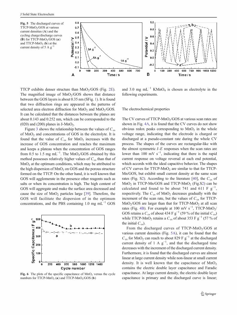
As the stability of the materials is a very important factorfor the electrochemical capacitors’ application, the stability of
the two samples have been evaluated by using CVmethod at ascan rate of 50 mV s−1 and the results are shown in Fig. 6. It isfound that the C sc of TTCP-MnO2 decreases slowly duringthe successive scan after it decreases from 410 (1st cycle) toabout 350 F g−1 at the 100th cycle (Fig. 6A), while the C cs ofTTCP-MnO2/GOS is kept constant or increases slightly afterit decreases from 489 to about 400 F g−1 during the repeated500 cycles (Fig. 6B). Finally, the Ccs retains 81.5 % of theinitial value for TTCP-MnO2/GOS and 82.3 % for TTCP-MnO2 after 1,500 cycles. Furthermore, the C cs of TTCP-MnO2/GOS is obviously larger than that of TTCP-MnO2
during the whole stability test process, which indicates thatthe incorporation of GOS into MnO2 can improve theperformance of the electrodes.
Conclusions
The hybrid of MnO2/GOS has been electrochemicallydeposited on the TTCP by co-deposition in the PBScontaining GOS and KMnO4. The resulted MnO2 ischaracterized to be birnessite and its morphology is stronglyinfluenced by the presence of GOS. The MnO2/GOS hybridexhibits larger Ccs and higher stability than that of MnO2
deposited on the TTCP, and may be used as electrodes in thesupercapacitors with high performance.
Acknowledgments The authors thank the National Natural ScienceFoundation of China (21274082 and 21073115) and Shanxi province(2012021021-3) the Program for New Century Excellent Talents inUniversity (NCET-10-0926) of China, and the Program for the TopYoung andMiddle-aged Innovative Talents of Shanxi province (TYMIT).
References
1. Broughton JN, Brett MJ (2005) Electrochim Acta 50:4814–48192. Yan J, Fan ZJ,Wei T, QianWZ, ZhangML,Wei F (2010) Carbon 48:
3825–38333. Simon P, Gogotsi Y (2008) Nat Mater 7:845–8544. Jin M, Han GY, Chang YZ, Zhao H, Zhang HY (2011) Electrochim
Acta 56:9838–98455. Wang XW, Liu SQ, Wang HY, Tu FY, Fang D, Li YH (2012) J Solid
State Electrochem 16:3593–36026. Wei J, Nagarajan N, Zhitomirsky I (2007) J Mater Process Technol
186:356–3617. Chang JK, Huang CH, Tsai WT, Deng MJ, Sun IW, Chen PY (2008)
Electrochim Acta 53:4447–44538. Devaraj S, Munichandraiah N (2005) Electrochem Solid-State Lett
8(7):A373–A3779. Hu CC, Tsou TW (2003) J Power Sources 115:179–186
10. Wei J, Zhitomirsky I (2008) Surf Eng 24:40–4611. Lee SW, Kim JY, Chen S, Hammond PT, Shaohorn Y (2010) ACS
Nano 4:3889–389612. Yu GH, Hu LB, Liu N, Wang HL, Vosgueritchian M, Yang Y, Cui Y,
Bao ZN (2011) Nano Lett 11:4438–4442
J Solid State Electrochem

13. Bordjiba T, Mohamedi M, Dao LH (2007) Nanotechnology18(035202):5
14. Wang Y, Yu SF, Sun CY, Zhu TJ, Yang HY (2012) J Mater Chem 22:17584–17588
15. Yuan LY, Lu XH, Xiao X, Zhai T, Dai JJ, Zhang FC, Hu B, Wang X,Gong L, Chen J, Hu CG, Tong YX, Zhou J, Wang ZL (2012) ACSNano 6:656–661
16. Zhang LL, Wei TX, Wang WJ, Zhao XS (2009) MicroporousMesoporous Mater 123:260–267
17. Amade R, Jover E, Caglar B, Mutlu T, Bertran E (2011) J PowerSources 196:5779–5783
18. Geim AK, Novoselov KS (2007) Nat Mater 6:183–19119. Guo S, Dong S (2011) Chem Soc Rev 40:2644–267220. Chen S, Zhu JW, Wu XD, Han QF, Wang X (2010) ACS Nano 4:
2822–283021. Zhao X, Zhang LL, Murali S, Stoller MD, Zhang QH, Zhu YW,
Ruoff RS (2012) ACS Nano 6:5404–541222. Cheng Q, Tang J, Ma J, Zhang H, Shinya N, Qin LC (2011) Carbon
49:2917–292523. Fan ZJ, Zhao QK, Li TY, Yan J, Ren YM, Feng J, Wei T (2012)
Carbon 50:1699–171224. Chang JK, Tsai WT (2003) J Electrochem Soc 150:A1333–A133825. Chang JK, Tsai WT (2004) J Appl Electrochem 34:953–96126. Chou SL, Wang JZ, Chew SY, Liu HK, Dou SX (2008) Electrochem
Commun 10:1724–172727. Wu MS, Guo ZS, Jow JJ (2010) J Phys Chem C 114:21861–21867
28. Zhu CZ, Guo SJ, Fang YX, Han L, Wang EK, Dong SJ (2011) NanoRes 4(7):648–657
29. Peng XY, Liu XX, Diamond D, Lau KT (2011) Carbon 49:3488–3496
30. Yang J, Gunasekaran S (2013) Carbon 51:36–4431. Chang YZ, Han GY, Li MY, Gao F (2011) Carbon 49:5158–516532. Sheng KX, XuYX, Li C, Shi GQ (2011) New CarbonMater 26:9–1533. Zhao H, Han GY, Chang YZ, Li MY, Li YP (2013) Electrochim Acta
91:50–5734. Raymundo-Pinero E, Gao Q, Beguin F (2013) Carbon 61:278–28335. Fu DY, Han GY, Chang YZ, Dong JH (2012) Mater Chem Phys 132:
673–68136. Bonhomme F, Lassegues JC, Servant L (2001) J Electrochem Soc
148:E450–E45837. Zhang XH, Li BX, Liu CY, Chu QX, Liu FY, Wang XF, Chen HW,
Liu XY (2013) Mater Res Bull 48:2696–270138. Julien C,Massot M, Baddour-Hadjean R, Franger S, Bach S, Pereira-
Ramos JP (2003) Solid State Ionics 159:345–35639. Fu DY, Han GY, Yang FF, Zhang TW, Chang YZ, Liu FF (2013)
Appl Surf Sci 283:654–65940. Zhang L, Shi GQ (2011) J Phys Chem C 115:17206–1721241. Khomenko V, Raymundo-Pinero E, Beguin F (2006) Appl Phys A
82:567–57342. Wang JG, Yang Y, Huang ZH, Kang FY (2013) Carbon 61:190–19943. Jin M, Liu YY, Li YL, Chang YZ, Fu DY, Zhao H, Han GY (2011) J
Appl Polym Sci 122:3415–3422
J Solid State Electrochem