Embed Size (px)
Citation preview
CM2-BASED PHYSICAL ITEM HIERARCHY IMPLEMENTATION FOR APRODUCT LIFECYCLE MANAGEMENT SYSTEM
A THESIS SUBMITTED TOTHE GRADUATE SCHOOL OF NATURAL AND APPLIED SCIENCES
OFMIDDLE EAST TECHNICAL UNIVERSITY
BY
DUYGU ABADAN SEVEN
IN PARTIAL FULFILLMENT OF THE REQUIREMENTSFOR
THE DEGREE OF MASTER OF SCIENCEIN
COMPUTER ENGINEERING
SEPTEMBER 2019

Approval of the thesis:
CM2-BASED PHYSICAL ITEM HIERARCHY IMPLEMENTATION FOR APRODUCT LIFECYCLE MANAGEMENT SYSTEM
submitted by DUYGU ABADAN SEVEN in partial fulfillment of the requirementsfor the degree of Master of Science in Computer Engineering Department, Mid-dle East Technical University by,
Prof. Dr. Halil KalıpçılarDean, Graduate School of Natural and Applied Sciences
Prof. Dr. Halit OguztüzünHead of Department, Computer Engineering
Prof. Dr. Halit OguztüzünSupervisor, Computer Engineering, METU
Dr. Emrah TufanCo-supervisor, METU
Examining Committee Members:
Prof. Dr. Pınar KaragözComputer Engineering, METU
Prof. Dr. Halit OguztüzünComputer Engineering, METU
Prof. Dr. Ahmet CosarComputer Engineering, UTAA
Date:

I hereby declare that all information in this document has been obtained andpresented in accordance with academic rules and ethical conduct. I also declarethat, as required by these rules and conduct, I have fully cited and referenced allmaterial and results that are not original to this work.
Name, Surname: Duygu Abadan Seven
Signature :
iv
ABSTRACT
CM2-BASED PHYSICAL ITEM HIERARCHY IMPLEMENTATION FOR APRODUCT LIFECYCLE MANAGEMENT SYSTEM
Seven, Duygu Abadan
M.S., Department of Computer Engineering
Supervisor: Prof. Dr. Halit Oguztüzün
Co-Supervisor: Dr. Emrah Tufan
September 2019, 66 pages
Configuration Management is a process that provides consistency among the prod-
uct requirements, the product itself, and associated product configuration information
by applying appropriate resources, processes, and tools. Configuration is an arrange-
ment of parts, requirements or data in a particular form, figure, or combination. There
can be one or more configuration for a product. Each of them needs to be managed
throughout its lifecycle. Software tools which are called Product Lifecycle Manage-
ment (PLM) tools provide a set of capabilities to manage product configurations and
all datasets associated with a product. There is an enterprise configuration manage-
ment methodology named CM2, proposed by Institute for Process Excellence (IpX),
which is also for enterprise product lifecycle change. In this study, generating phys-
ical item hierarchy (As Planned/As Released Baseline) which is the first step of the
core business processes of CM2 has been integrated to a PLM tool. Owing to this
implementation, the generated physical item hierarchy enables to analyze the prod-
uct with its connected datasets during the development and the production phases
and to increase the potential of reuse existing items and associated documents. The
v
contribution of generating physical item hierarchy through the PLM system to the
configuration management applications in the defense industry is explained in the
case study.
Keywords: As planned/as released baseline, CM2, configuration management, phys-
ical item hierarchy, product lifecycle management
vi
ÖZ
ÜRÜN YASAM DÖNGÜSÜ YÖNETIM SISTEMI IÇIN CM2 TABANLIFIZIKSEL KALEM HIYERARSISI UYGULAMASI
Seven, Duygu Abadan
Yüksek Lisans, Bilgisayar Mühendisligi Bölümü
Tez Yöneticisi: Prof. Dr. Halit Oguztüzün
Ortak Tez Yöneticisi: Dr. Emrah Tufan
Eylül 2019 , 66 sayfa
Konfigürasyon Yönetimi, uygun kaynaklar, islemler ve araçlar kullanarak ürün ge-
reksinimleri, ürünün kendisi ve ilgili ürün konfigürasyon bilgileri arasında tutarlılıgı
saglayan bir süreçtir. Konfigürasyon, belirli bir biçimde, sekilde veya kombinasyonda
olan parçaların, gereksinimlerin veya verilerin bir düzenlemesidir. Bir ürün için bir
veya daha fazla konfigürasyon olabilir. Bunlardan her birinin kullanım ömrü bo-
yunca yönetilmesi gerekir. Ürün Yasam Döngüsü Yönetimi (PLM) araçları olarak
adlandırılan yazılım araçları, ürün konfigürasyonlarını ve ürün ile iliskilendirilmis
tüm veri setlerini yönetmek için bir dizi özellik saglar. Kurumsal ürün yasam döngüsü
degisikligi için de geçerli olan CM2 adında, Süreç Mükemmelligi Enstitüsü tarafndan
tasarlanan, kurumsal konfigürasyon yönetim yöntemi vardır. Bu çalısmada, CM2’nin
temel is süreçlerinin ilk adımı olan fiziksel kalem hiyerarsisi olusturma (Planlandıgı
gibi/Yayınlandıgı gibi Ana Çizgilendirme) PLM aracına dahil edilmistir. Bu uygu-
lama sayesinde, olusturulan fiziksel kalem hiyerarsisi, ürünlerin, baglanan veri set-
leriyle beraber gelistirme ve üretim asamaları boyunca analiz edilmesini ve mev-
cut kalemler ve iliskili dokümanların yeniden kullanılma potansiyelinin arttırılmasını
vii

saglar. Örnek çalısmada PLM sistemi aracılıgıyla fiziksel kalem hiyerarsisi olusturmanın
savunma sanayindeki konfigürasyon yönetim uygulamalarına katkısı açıklanmıstır.
Anahtar Kelimeler: Planlandıgı gibi/yayınlandıgı gibi ana çizgi, CM2, konfigürasyon
yönetimi, fiziksel kalem hiyerarsisi, ürün yasam döngüsü yönetimi
viii

To my dearest family and husband
ix
ACKNOWLEDGMENTS
I would like to thank my supervisor Prof. Dr. Halit Oguztüzün for his guidance,
patience and understanding.
I would like to thank my co-supervisor Dr. Emrah Tufan for mentoring me and for
teaching me in the field of the configuration management and product lifecycle man-
agement.
I would like to thank my colleagues and executives in the configuration and product
management division of the company for their help and support.
I would like to thank my friends who have encouraged and supported me.
Finally, I sincerely thank my family and husband for their sacrifice, support, encour-
agement and belief.
x
TABLE OF CONTENTS
ABSTRACT . . . . . . . . . . . . . . . . . . . . . . . . . . . . . . . . . . . . v
ÖZ . . . . . . . . . . . . . . . . . . . . . . . . . . . . . . . . . . . . . . . . . vii
ACKNOWLEDGMENTS . . . . . . . . . . . . . . . . . . . . . . . . . . . . . x
TABLE OF CONTENTS . . . . . . . . . . . . . . . . . . . . . . . . . . . . . xi
LIST OF TABLES . . . . . . . . . . . . . . . . . . . . . . . . . . . . . . . . xiv
LIST OF FIGURES . . . . . . . . . . . . . . . . . . . . . . . . . . . . . . . . xv
LIST OF ABBREVIATIONS . . . . . . . . . . . . . . . . . . . . . . . . . . . xviii
CHAPTERS
1 INTRODUCTION . . . . . . . . . . . . . . . . . . . . . . . . . . . . . . . 1
1.1 Overview of Product Lifecycle Management Systems . . . . . . . . . 1
1.2 Product Configuration Management in PLM System . . . . . . . . . 2
1.3 Motivation . . . . . . . . . . . . . . . . . . . . . . . . . . . . . . . 3
1.4 Organization of the Thesis . . . . . . . . . . . . . . . . . . . . . . . 4
2 BACKGROUND . . . . . . . . . . . . . . . . . . . . . . . . . . . . . . . . 5
2.1 Configuration Management . . . . . . . . . . . . . . . . . . . . . . 5
2.2 Traditional CM versus CM2 . . . . . . . . . . . . . . . . . . . . . . 6
2.3 Product Lifecycle Management . . . . . . . . . . . . . . . . . . . . 8
2.3.1 PLM System . . . . . . . . . . . . . . . . . . . . . . . . . . . 9
xi
2.4 Literature Review . . . . . . . . . . . . . . . . . . . . . . . . . . . . 11
3 PHYSICAL ITEM HIERARCHY . . . . . . . . . . . . . . . . . . . . . . . 15
3.1 Definition . . . . . . . . . . . . . . . . . . . . . . . . . . . . . . . . 15
3.2 CM2 Approach for Product Structure . . . . . . . . . . . . . . . . . 16
3.2.1 Design Basis . . . . . . . . . . . . . . . . . . . . . . . . . . . 17
3.2.2 Physical Item Hierarchy . . . . . . . . . . . . . . . . . . . . . 19
3.2.3 As-Planned/As-Released Baseline . . . . . . . . . . . . . . . 21
4 TOOL EXTENSION . . . . . . . . . . . . . . . . . . . . . . . . . . . . . 25
4.1 Scope of the Tool Extension . . . . . . . . . . . . . . . . . . . . . . 25
4.2 Design Details of the Tool Extension . . . . . . . . . . . . . . . . . 27
4.2.1 Software Requirement Analysis . . . . . . . . . . . . . . . . . 27
4.2.2 Software Design Details . . . . . . . . . . . . . . . . . . . . . 30
5 CASE STUDY FROM EMERALD COMPANY . . . . . . . . . . . . . . . 41
5.1 Telemetry System . . . . . . . . . . . . . . . . . . . . . . . . . . . . 41
5.2 Functional Validation . . . . . . . . . . . . . . . . . . . . . . . . . . 49
5.3 Usability Test . . . . . . . . . . . . . . . . . . . . . . . . . . . . . . 51
6 CONCLUSION . . . . . . . . . . . . . . . . . . . . . . . . . . . . . . . . 53
6.1 Achievements . . . . . . . . . . . . . . . . . . . . . . . . . . . . . . 53
6.2 Future Work . . . . . . . . . . . . . . . . . . . . . . . . . . . . . . 54
REFERENCES . . . . . . . . . . . . . . . . . . . . . . . . . . . . . . . . . . 55
APPENDICES
A SPINNER EXCEL FILES . . . . . . . . . . . . . . . . . . . . . . . . . . . 59
xii
B CMII BASELINE OF TELEMETRY SYSTEM . . . . . . . . . . . . . . . 65
xiii
LIST OF TABLES
TABLES
Table 2.1 Business Process Infrastructure . . . . . . . . . . . . . . . . . . . . 7
Table 2.2 Generic PLM Applications . . . . . . . . . . . . . . . . . . . . . . 9
Table 3.1 Core Business Processes . . . . . . . . . . . . . . . . . . . . . . . 21
Table 4.1 Summary of Use Cases . . . . . . . . . . . . . . . . . . . . . . . . 28
xiv
LIST OF FIGURES
FIGURES
Figure 2.1 Product lifecycle phases . . . . . . . . . . . . . . . . . . . . . . 8
Figure 2.2 CAD model of the example aircraft . . . . . . . . . . . . . . . . 10
Figure 3.1 Physical item hierarchy draft . . . . . . . . . . . . . . . . . . . 15
Figure 3.2 V-model for development [15] . . . . . . . . . . . . . . . . . . 16
Figure 3.3 4-Tier, 9 step CM2 process [16] . . . . . . . . . . . . . . . . . 17
Figure 3.4 Design basis of end item [15] . . . . . . . . . . . . . . . . . . . 18
Figure 3.5 Physical item hierarchy [18] . . . . . . . . . . . . . . . . . . . 19
Figure 3.6 Relation between primary and secondary items/documents [16] . 20
Figure 3.7 As-planned/as-released baseline [16] . . . . . . . . . . . . . . . 22
Figure 3.8 Physical item hierarchy with change example . . . . . . . . . . 24
Figure 3.9 As-planned/as-released baseline of change example [18] . . . . 24
Figure 4.1 Block diagram . . . . . . . . . . . . . . . . . . . . . . . . . . . 25
Figure 4.2 Engineering BOM table of illustrative example . . . . . . . . . . 26
Figure 4.3 Use case diagram for designer/administrator . . . . . . . . . . . 27
Figure 4.4 Use case diagram for configuration specialist/manufacturing plan-
ning specialist . . . . . . . . . . . . . . . . . . . . . . . . . . . . . . . 28
xv
Figure 4.5 Top level component diagram . . . . . . . . . . . . . . . . . . . 30
Figure 4.6 Context diagram . . . . . . . . . . . . . . . . . . . . . . . . . . 31
Figure 4.7 Class diagram . . . . . . . . . . . . . . . . . . . . . . . . . . . 32
Figure 4.8 Activity diagram of customization functions . . . . . . . . . . . 33
Figure 4.9 Properties screen of end item . . . . . . . . . . . . . . . . . . . 34
Figure 4.10 Physical item hierarchy of illustrative example . . . . . . . . . . 35
Figure 4.11 CMII Baseline page . . . . . . . . . . . . . . . . . . . . . . . . 36
Figure 4.12 CMII Baseline download page . . . . . . . . . . . . . . . . . . 37
Figure 4.13 CMII Baseline excel view . . . . . . . . . . . . . . . . . . . . . 37
Figure 4.14 Sequence diagram for tool extension functions . . . . . . . . . . 38
Figure 5.1 Missile test example of telemetry system overview [14] . . . . . 42
Figure 5.2 Missile telemetry system . . . . . . . . . . . . . . . . . . . . . 43
Figure 5.3 CAD model of the telemetry system . . . . . . . . . . . . . . . 44
Figure 5.4 Physical item hierarchy view of the telemetry system . . . . . . 44
Figure 5.5 CMII Baseline view of the telemetry system . . . . . . . . . . . 46
Figure 5.6 CMII Baseline of the telemetry system cont. . . . . . . . . . . . 47
Figure 5.7 CMII Baseline of the telemetry system cont. . . . . . . . . . . . 48
Figure 5.8 Excel output of CMII Baseline of the telemetry system . . . . . 49
Figure A.1 Spinner command data . . . . . . . . . . . . . . . . . . . . . . 60
Figure A.2 Spinner menu data . . . . . . . . . . . . . . . . . . . . . . . . . 61
Figure A.3 Spinner table data . . . . . . . . . . . . . . . . . . . . . . . . . 61
Figure A.4 Spinner table column data . . . . . . . . . . . . . . . . . . . . . 62
xvi
Figure A.5 Spinner web form field data . . . . . . . . . . . . . . . . . . . . 63
Figure B.1 CMII Baseline of telemetry system . . . . . . . . . . . . . . . . 66
xvii
LIST OF ABBREVIATIONS
BOM Bill of materials
CAD Computer-aided design
CAGE Commercial and government entity
CAM Computer-aided manufacturing
CM Configuration management
CMII CM2
COTS Commercial off-the-shelf
EBOM Engineering bill of material
ECN Enterprise change notice
ESR Externally source record
JSP Java server pages
MQL Matrix query language
OOTB Out of the box
PDM Product data management
PLM Product lifecycle management
RF Radio frequency
UI User interface
UML Unified modeling language
xviii
CHAPTER 1
INTRODUCTION
1.1 Overview of Product Lifecycle Management Systems
Due to the complex nature of today’s products, digitalization is an essential for whole
product lifecycle. Data belonging to product needs to be kept and managed on digital
platform for traceability. Even though traceability is one of the most important rea-
sons, there are many other advantages of digitalization in addition. Digital systems
are easily accessible and this provides time saving and multiple access at the same
time. Data stored within the digital platform can be organized, standardized and sus-
tainable. It is easy to manage, analyze and report. In addition, digitized information
in one system is single source of truth so it is reliable and consistent.
Digitalization of product related data started with Product Data Management (PDM)
systems in the late of 1980s [7]. PDM systems are used to store Computer-Aided
Design/Computer-Aided Manufacturing (CAD/CAM) data files. PDM systems are
file-based systems. They are not sufficient for managing products. The need to man-
age the entire lifecycle of the product has led to the emergence of the PLM systems.
Product Lifecycle Management (PLM) is a concept that emerged in the early 2000s
[27]. PLM system is one of digital platforms that enables to manage information
related with the products. All data related with the product are kept in PLM systems.
After development of PLM system, PDM is one of the most important elements of the
PLM environment which manages all the product data created and used throughout
the product lifecycle and provide exactly the right information at exactly the right
time [27].
1
In the PLM systems, data that cover the entire lifecycle of product are controlled
and managed by cross-functional teams, the entire product data stream is in order
according to workflow. Owing to this, it contains all the necessary components such
as 3D models, drawings and technical data sets, pertaining to every stage of their life
cycle, hence, it supports digitalization of products in all aspects.
PLM system brings benefit for companies with a wide range of products in terms
of time saving, ease of development, product excellence and competition. Users of
PLM system can access product related data easily. Cross functional teams can work
together on same platform at the same time. Designers can develop products in a
shorter time frame. Products are ready to market in less time. Product related costs
reduce owing to facilitated prototyping and reuse. These kind of benefits maximize
the value of product portfolio and enhance competitiveness.
1.2 Product Configuration Management in PLM System
Lexical meaning of configuration is an arrangement of parts or elements in a partic-
ular form, figure, or combination [22]. Creating a product means creating a product
configuration comprised of parts or elements. Product configuration is the princi-
pal concept in PLM systems. Product configuration contains functional and physical
features of the product. PLM systems offer a set of mechanisms in order to sup-
port product configuration management [19]. These mechanisms include creating
and controlling documents, design and development of the parts, creating physical
structure of them, setting connections between parts and documents and supporting
maintenance of product life.
In PLM systems, functional and physical features of product is defined in metadata
and datasets in preliminary state. Datasets can be design drawings and specifications.
After design is completed according to specifications and product is mature enough,
it is presented to review. In this state, CM specialists control and validate the datasets
and the structure of the product. Structure of the product is usually controlled over
Bill of Materials (BOM). It is the breakdown structure of part objects for a product.
Not only development and structure validation is included in the scope of configura-
2
tion management, but also change validation is included. Change management is a
big topic itself and is part of configuration management. PLM system is also able to
manage product changes. Product structure is not be restricted with BOM in PLM
systems. It can be built as physical item hierarchy. Physical item hierarchy contains
BOM as a document. A baseline can be generated from the physical item hierarchy
and it includes BOM and change information of items.
PLM software enables to provide configuration identification, control, status account-
ing and verification and to track product baselines and workflows in each step of prod-
uct life. It can provide them according to CM standards. The PLM tool vendors might
implement CM standards in their tool. These standards can be military standards
like MIL-STD-973, commercial standards like ISO 10007 or enterprise standard like
CM2. Developed PLM tool as to CM standards helps manage product configura-
tion faultlessly. In short, digitalization of the product life cycle with PLM systems
simplifies configuration management and makes it in compliance with standards.
1.3 Motivation
Physical item hierarchy is a set of hierarchical items such as parts, assemblies or com-
ponents that constitutes product structure. The PLM software tool that is used in a
defense companies enables to represent physical item hierarchy with bill of material
(BOM). A BOM is simply defined as a compilation of parts list for a product [32].
However, the BOM is a document that should be included in the physical item hierar-
chy according to CM2. When the defense company wants to manage configurations
according to CM2 standards, the PLM tool in use might not support CM2 standards
in every aspect. In such situation, there are two options. One is to change the PLM
tool but it requires to migrate all data to new system. It is huge and complex process
and costly. Another one is to customize the PLM tool. It is easier with respect to
first option if customization of the PLM tool is possible from a technical aspect. In
this study, CM2-based physical item hierarchy is created as an alternative to BOM to
adapt the PLM tool to CM2 by customization. Moreover, CM2 baseline that is known
as As Planned/As Released Baseline is generated from the CM2-based physical item
hierarchy.
3
Whereas change is not traced from BOM, the traceability of change is provided
with adaptation of the PLM tool to CM2 on the subject of CM2 baseline. Since As
Planned/As Released Baseline includes effectivity of items which is an indicator for
validity and feasibility, effectivity is managed and it is useful for change management.
The output of CM2 baseline provides input to technical data package which is deliv-
ered to customer to describe the product structure. It is necessity for standardization
of technical data package. Moreover, it provides input to project management tool
to create work package that is a set of assigned tasks. Thus, project can be planned
hierarchically. It supports to address complexity, promote reuse and manage product
line.
1.4 Organization of the Thesis
The thesis describes CM2-based product structure model implementation in a PLM
system. It is organized as follows. In Chapter 2, background information is given
about the configuration management, CM2 and PLM. In addition, previous studies
about product structuring are investigated.
In Chapter 3, the physical item hierarchy model of CM2 methodology and CM2 base-
line are explained in detail.
In Chapter 4, the implementation of the physical item hierarchy and as released base-
line in a PLM system is explained by defining software requirements and design de-
tails.
In Chapter 5, the usage of PLM tool customization is described through the case
study in the defense industry. Functional validation and usability test of the study is
performed.
In Chapter 6, the thesis is summarized and concluded. The developmental aspects of
the thesis are described as future work.
4
CHAPTER 2
BACKGROUND
2.1 Configuration Management
Configuration Management (CM) is a comprehensive process for maintaining con-
sistency of any product’s performance, functional and physical attributes with its re-
quirements, design, and operational information [2]. This definition of the military
standard is taken as a basis in defense industry and this standard offers universal ap-
proach for configuration management by defining the common sense CM applications
and their underlying fundamental principles. In other words, it describes all informa-
tion related with the configuration management by defining what should be done and
why they should be done.
CM is a critical discipline since it controls the suitability of datasets for the product
and provides pre-manufacturing control. Datasets can be design document, process
plan and bill of material (BOM). The suitability of the datasets to the product is very
important for the accurate and clear manufacturing. Without minimum control of de-
sign documents via make-sense processes, practices and measurements, chaos ensues
[33]. Chaos causes misdesigning and corrective actions. Therefore, configuration
management discipline is a factor that directly affects cost. Although there is such
a critical discipline, the organizational culture is very effective in applying configu-
ration management accurately. Standards like Configuration Management Standard
ANSI/EIA-649B or CM2 are intended to make configuration management indepen-
dent of the corporate culture. Moreover, the standards enable the globalization of
configuration management in the most effective way rather than according to the cor-
porate culture.
5
Wherever the product exists, configuration management is mentioned there. When the
product configurations is managed correctly, configuration management provides a lot
of benefits to manufacturers if done correctly. Frank B. Watts outlines the importance
of CM in the following way [33].
CM is a requirement in almost every product manufacturing operation because of the
following:
• Design documentation is one of the four critical elements of profitable product
manufacturing.
• Design documentation is engineering’s product and that documentation is re-
quired by almost all the company functions.
• Designs do change and changes need to be accurate, understood, communi-
cated, and tracked.
• Most companies have a degree of chaos, over-control or both in the CM world.
• A function is needed to bridge the gap caused by the lack of communication be-
tween engineering and manufacturing teams often found between engineering
and the rest of the company [34].
• An executive champion is needed for fostering best-in-class CM.
2.2 Traditional CM versus CM2
Institute for Process Excellence (IpX) is an organization that helps to modernize
and integrate company’s legacy processes, systems, people, and data [12]. CM2 is
the global industry standard that is proposed by IpX for enterprise product lifecy-
cle change and configuration management [11]. As product complexity increases
and organizations become more reliant on their supply chains, managing the change
process and communicating across the global digital ecosystem is an increasing chal-
lenge. Ineffective and inefficient organization structures, processes, and systems leave
organizations struggling to improve quality, reduce time-to-market and manage costs
[11]. In other words, CM2 is new generation configuration management methodology
6
that provides a path to integrate process excellence dependent on the availability of
appropriate business process infrastructure [35]. In addition to the traditional configu-
ration management, it also describes how to manage products by operating standards.
While traditional CM includes only products and design documents, CM2 expands
the content in terms of not only engineering but also enterprise wide perspective of
the change. This perspective covers all the information that affects safety, security,
quality, schedule, cost, profit and facility. CM2 puts emphasis on accommodating
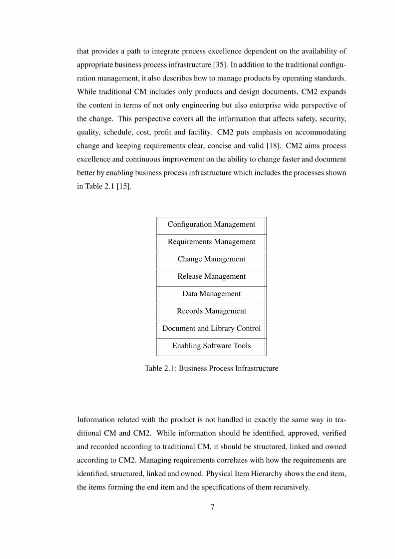
change and keeping requirements clear, concise and valid [18]. CM2 aims process
excellence and continuous improvement on the ability to change faster and document
better by enabling business process infrastructure which includes the processes shown
in Table 2.1 [15].
Configuration Management
Requirements Management
Change Management
Release Management
Data Management
Records Management
Document and Library Control
Enabling Software Tools
Table 2.1: Business Process Infrastructure
Information related with the product is not handled in exactly the same way in tra-
ditional CM and CM2. While information should be identified, approved, verified
and recorded according to traditional CM, it should be structured, linked and owned
according to CM2. Managing requirements correlates with how the requirements are
identified, structured, linked and owned. Physical Item Hierarchy shows the end item,
the items forming the end item and the specifications of them recursively.
7
2.3 Product Lifecycle Management
Product Lifecycle Management (PLM) is the business activity of managing, in the
most effective way, a companys products all the way across their life cycles; from the
very first idea for a product all the way through until it is retired and disposed of [27].
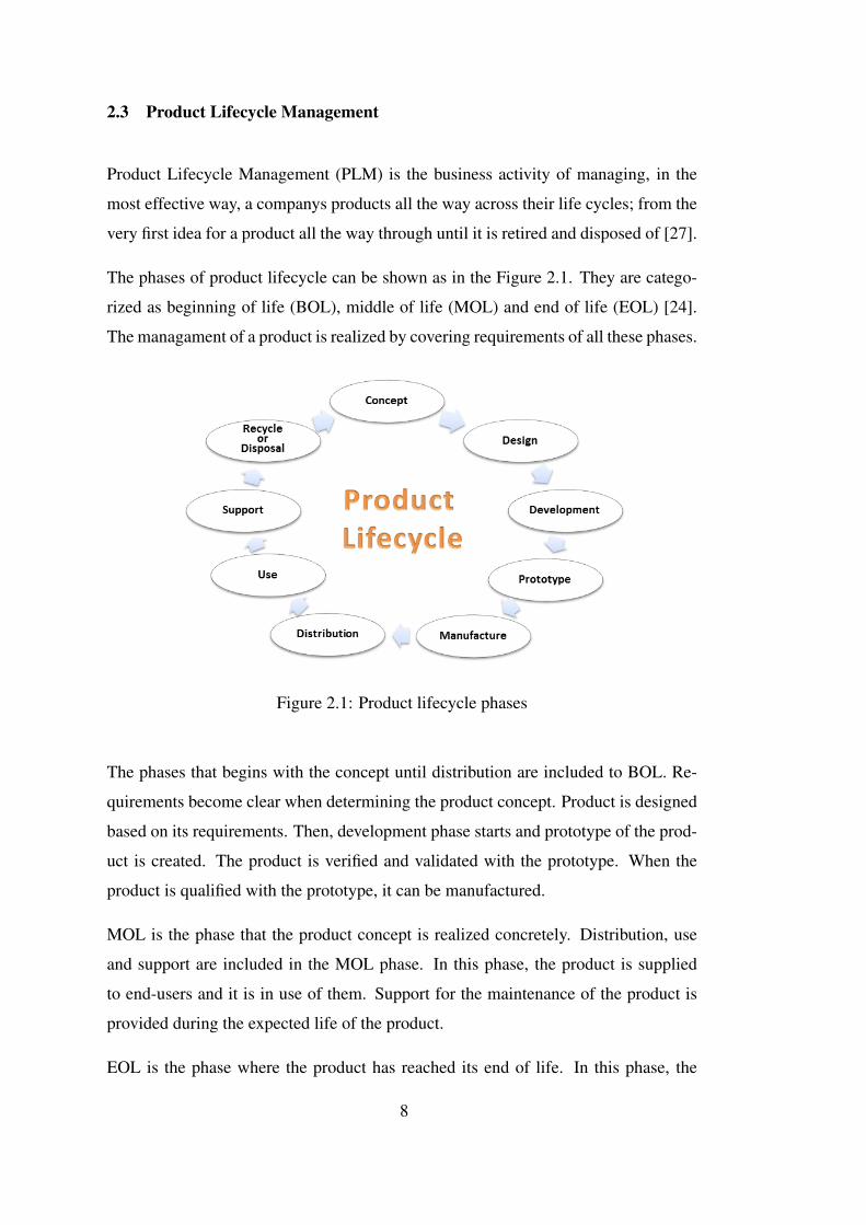
The phases of product lifecycle can be shown as in the Figure 2.1. They are catego-
rized as beginning of life (BOL), middle of life (MOL) and end of life (EOL) [24].
The managament of a product is realized by covering requirements of all these phases.
Figure 2.1: Product lifecycle phases
The phases that begins with the concept until distribution are included to BOL. Re-
quirements become clear when determining the product concept. Product is designed
based on its requirements. Then, development phase starts and prototype of the prod-
uct is created. The product is verified and validated with the prototype. When the
product is qualified with the prototype, it can be manufactured.
MOL is the phase that the product concept is realized concretely. Distribution, use
and support are included in the MOL phase. In this phase, the product is supplied
to end-users and it is in use of them. Support for the maintenance of the product is
provided during the expected life of the product.
EOL is the phase where the product has reached its end of life. In this phase, the
8
question of what to do with product reaching the end of its life is asked. The answer
of this question can be disassembling, refurbishing, recycling, reassembling, reusing
or disposing. Products are disassembled if they will be recycled [4]. Products are
refurbished if they will be re-manufactured. The parts of product can be reassembled
for reuse. If the product will be eliminated without any part of it is not recycled, it
can be scrapped for disposal.
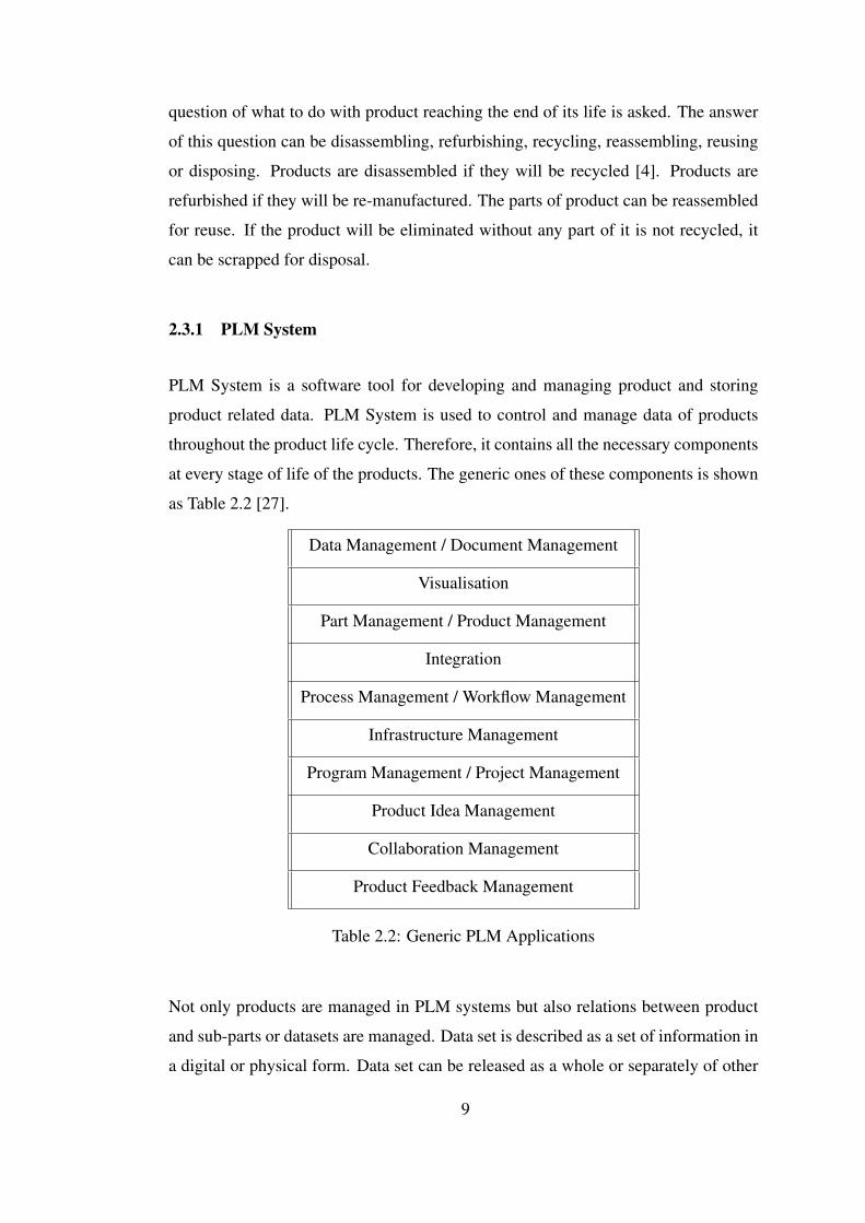
2.3.1 PLM System
PLM System is a software tool for developing and managing product and storing
product related data. PLM System is used to control and manage data of products
throughout the product life cycle. Therefore, it contains all the necessary components
at every stage of life of the products. The generic ones of these components is shown
as Table 2.2 [27].
Data Management / Document Management
Visualisation
Part Management / Product Management
Integration
Process Management / Workflow Management
Infrastructure Management
Program Management / Project Management
Product Idea Management
Collaboration Management
Product Feedback Management
Table 2.2: Generic PLM Applications
Not only products are managed in PLM systems but also relations between product
and sub-parts or datasets are managed. Data set is described as a set of information in
a digital or physical form. Data set can be released as a whole or separately of other
9
data sets. PLM manages the whole range, from individual part through individual
product to the entire portfolio of products [27].
The structure of the PLM system is established according to business processes. Un-
less the processes are accurate and detailed, PLM systems cannot be more than just
a tool. If PLM systems are to be used with the highest efficiency, processes should
be well defined. CM2 also advocates this idea. PLM systems help users to access the
right document, at the right place, at the right time if there is a process they can apply
[32]. When the processes affect more than one division concurrently, PLM systems
are used by cross-functional teams. The task of PLM, in one sense, is to provide the
necessary conditions for connecting separate information data systems, processes and
automation islets [25].
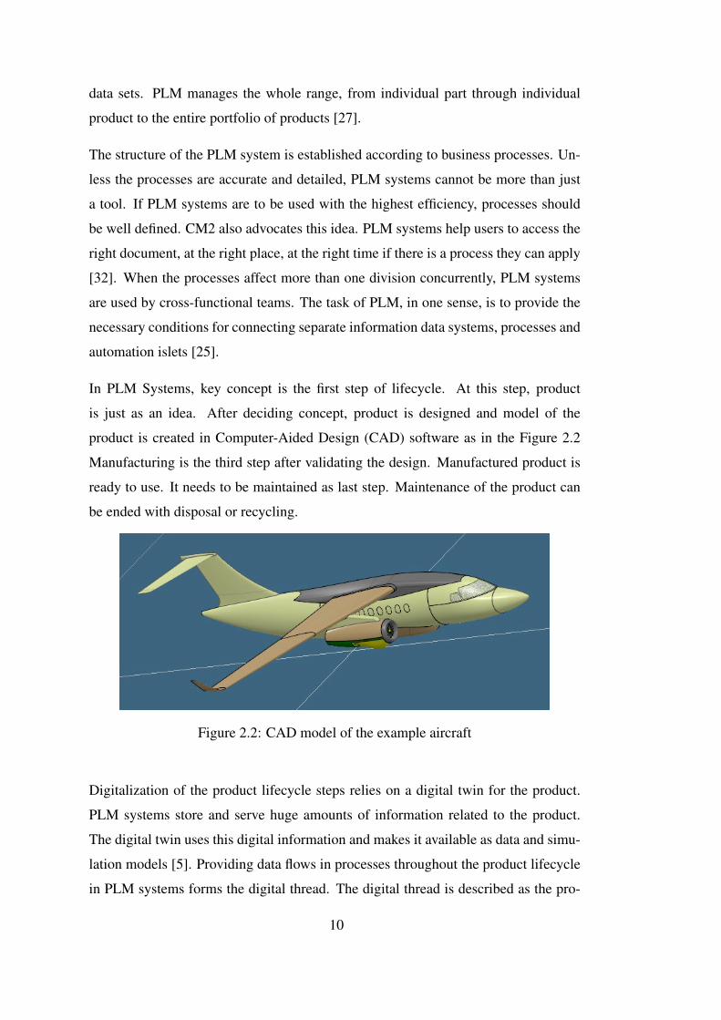
In PLM Systems, key concept is the first step of lifecycle. At this step, product
is just as an idea. After deciding concept, product is designed and model of the
product is created in Computer-Aided Design (CAD) software as in the Figure 2.2
Manufacturing is the third step after validating the design. Manufactured product is
ready to use. It needs to be maintained as last step. Maintenance of the product can
be ended with disposal or recycling.
Figure 2.2: CAD model of the example aircraft
Digitalization of the product lifecycle steps relies on a digital twin for the product.
PLM systems store and serve huge amounts of information related to the product.
The digital twin uses this digital information and makes it available as data and simu-
lation models [5]. Providing data flows in processes throughout the product lifecycle
in PLM systems forms the digital thread. The digital thread is described as the pro-
10
cess for capturing data throughout the product lifecycle and analyzing opportunities
to drive down tooling costs and lead times, improving efficiencies and promoting
innovation by digitizing the supply chain, manufacturing processes, parts, and in-
service data [21]. Owing that PLM systems enable digital twin and digital thread, the
product and the communication among the product lifecycle steps are digitized. This
digitalization provides full lifecycle traceability for the product.
At the highest level, the objective of PLM is to increase product revenues, reduce
product-related costs, maximise the value of the product portfolio, and maximise the
value of current and future products for both customers and shareholders [28]. To
achieve this goal, configuration management must be applied according to operating
standards and these operating standards must be performed correctly. This is a part of
the process, this is not the responsibility of the PLM system, as PLM system is just a
tool for managing product configurations in a digital environment.
2.4 Literature Review
In the literature, there are some works related to various PLM implementations and
product structure. Boton et al. [6] studied comparison of PLM and Building Infor-
mation Modelling (BIM) from the product structure point of view. Bill of Material
(BOM) is examined for the product structure. It is the breakdown structure of part ob-
jects for a product. In that study, BOM is a document in the physical item hierarchy;
it does not show whole product structure alone as this study.
Schuh et al.’s study [26] presents product structure with a set of six customized ref-
erence models by addressing the specific needs of each existing project type. In their
approach, all products related data is represented by product structure. It shows sim-
ilarity with our study since both emphasize that PLM is a systematical concept to de-
sign, manage and control all the information related with the product and the product
structure is key element of PLM. That study declares that product structuring starts
with the requirements identification of every stakeholder along the entire product life-
cycle. That is the common point of our study since CM2 defends that development
plan starts with the definition of the application requirements and the basis for detailed
11
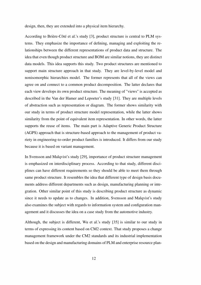
design, then, they are extended into a physical item hierarchy.
According to Brière-Côté et al.’s study [3], product structure is central to PLM sys-
tems. They emphasize the importance of defining, managing and exploiting the re-
lationships between the different representations of product data and structure. The
idea that even though product structure and BOM are similar notions, they are distinct
data models. This idea supports this study. Two product structures are mentioned to
support main structure approach in that study. They are level-by-level model and
nonisomorphic hierarchies model. The former represents that all of the views can
agree on and connect to a common product decomposition. The latter declares that
each view develops its own product structure. The meaning of "views" is accepted as
described in the Van der Hamer and Lepoeter’s study [31]. They are multiple levels
of abstraction such as representation or diagram. The former shows similarity with
our study in terms of product structure model representation, while the latter shows
similarity from the point of equivalent item representation. In other words, the latter
supports the reuse of items. The main part is Adaptive Generic Product Structure
(AGPS) approach that is structure-based approach to the management of product va-
riety in engineering-to-order product families is introduced. It differs from our study
because it is based on variant management.
In Svensson and Malqvist’s study [29], importance of product structure management
is emphasized on interdisciplinary process. According to that study, different disci-
plines can have different requirements so they should be able to meet them through
same product structure. It resembles the idea that different type of design basis docu-
ments address different departments such as design, manufacturing planning or inte-
gration. Other similar point of this study is describing product structure as dynamic
since it needs to update as to changes. In addition, Svensson and Malqvist’s study
also examines the subject with regards to information system and configuration man-
agement and it discusses the idea on a case study from the automotive industry.
Although, the subject is different, Wu et al.’s study [35] is similar to our study in
terms of expressing its content based on CM2 context. That study proposes a change
management framework under the CM2 standards and its industrial implementation
based on the design and manufacturing domains of PLM and enterprise resource plan-
12
ing (ERP) systems. While Wu et al.’s study clarifies change management according
to CM2 standards, our study clarifies product structure. Both explain the main idea
through the perspective of the PLM.
13

14
CHAPTER 3
PHYSICAL ITEM HIERARCHY
Creating physical item hierarchy is a main point of this thesis. In this section, CM2
approach for physical item hierarchy is explained and how a baseline is derived from
physical item hierarchy is described.
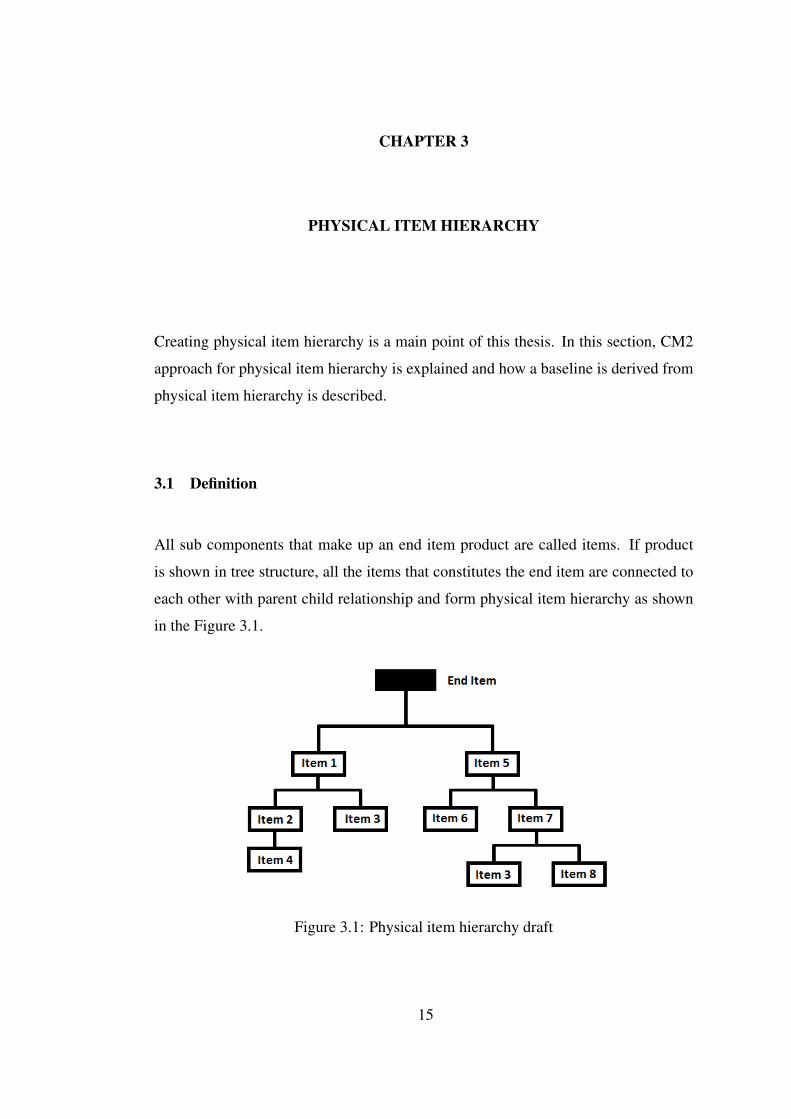
3.1 Definition
All sub components that make up an end item product are called items. If product
is shown in tree structure, all the items that constitutes the end item are connected to
each other with parent child relationship and form physical item hierarchy as shown
in the Figure 3.1.
Figure 3.1: Physical item hierarchy draft
15
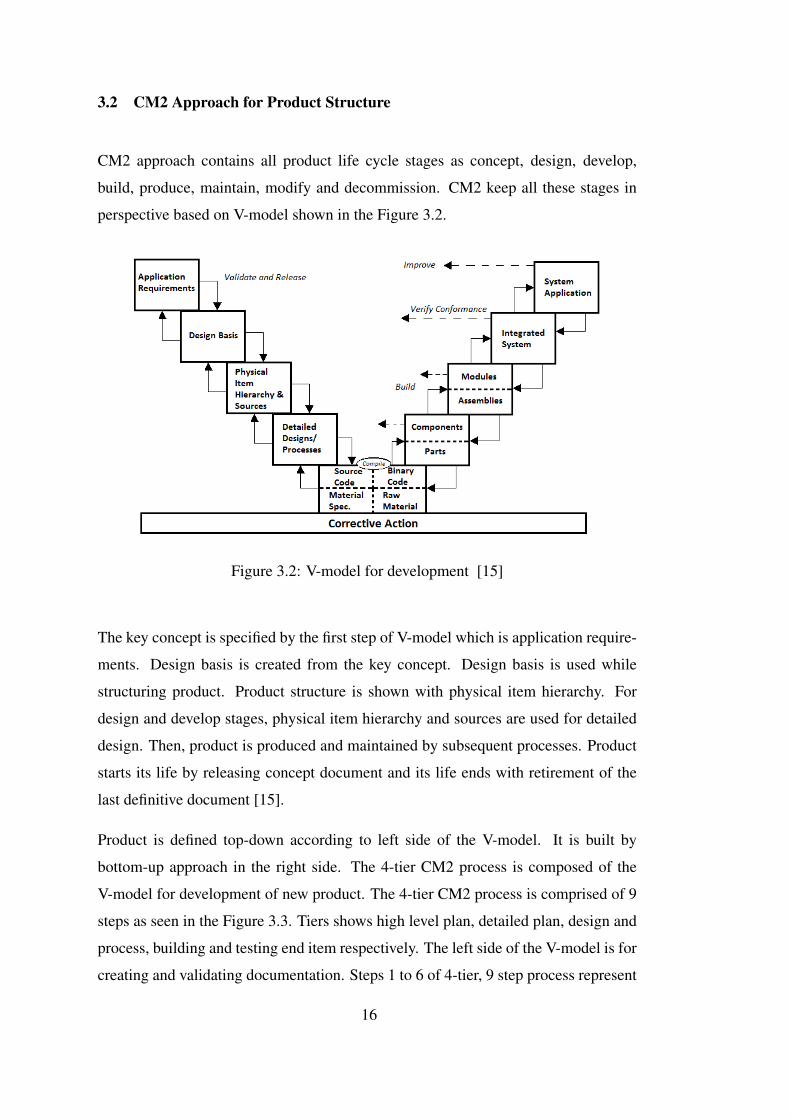
3.2 CM2 Approach for Product Structure
CM2 approach contains all product life cycle stages as concept, design, develop,
build, produce, maintain, modify and decommission. CM2 keep all these stages in
perspective based on V-model shown in the Figure 3.2.
Figure 3.2: V-model for development [15]
The key concept is specified by the first step of V-model which is application require-
ments. Design basis is created from the key concept. Design basis is used while
structuring product. Product structure is shown with physical item hierarchy. For
design and develop stages, physical item hierarchy and sources are used for detailed
design. Then, product is produced and maintained by subsequent processes. Product
starts its life by releasing concept document and its life ends with retirement of the
last definitive document [15].
Product is defined top-down according to left side of the V-model. It is built by
bottom-up approach in the right side. The 4-tier CM2 process is composed of the
V-model for development of new product. The 4-tier CM2 process is comprised of 9
steps as seen in the Figure 3.3. Tiers shows high level plan, detailed plan, design and
process, building and testing end item respectively. The left side of the V-model is for
creating and validating documentation. Steps 1 to 6 of 4-tier, 9 step process represent
16
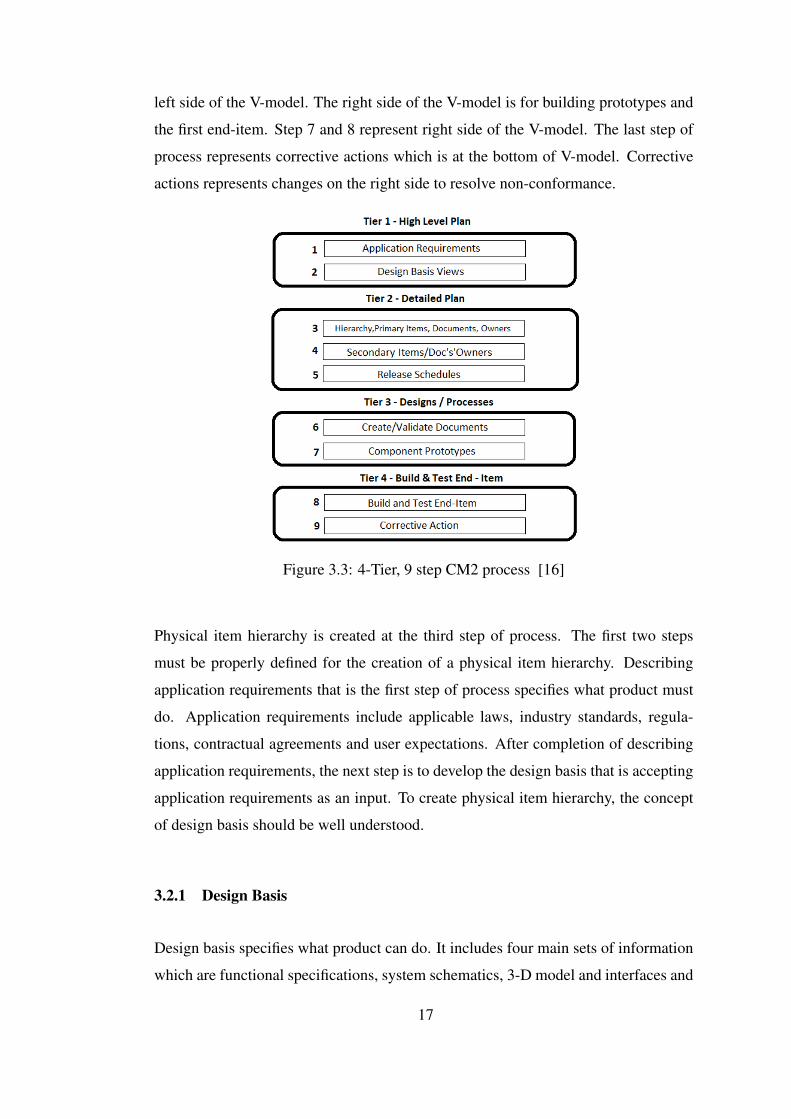
left side of the V-model. The right side of the V-model is for building prototypes and
the first end-item. Step 7 and 8 represent right side of the V-model. The last step of
process represents corrective actions which is at the bottom of V-model. Corrective
actions represents changes on the right side to resolve non-conformance.
Figure 3.3: 4-Tier, 9 step CM2 process [16]
Physical item hierarchy is created at the third step of process. The first two steps
must be properly defined for the creation of a physical item hierarchy. Describing
application requirements that is the first step of process specifies what product must
do. Application requirements include applicable laws, industry standards, regula-
tions, contractual agreements and user expectations. After completion of describing
application requirements, the next step is to develop the design basis that is accepting
application requirements as an input. To create physical item hierarchy, the concept
of design basis should be well understood.
3.2.1 Design Basis
Design basis specifies what product can do. It includes four main sets of information
which are functional specifications, system schematics, 3-D model and interfaces and
17
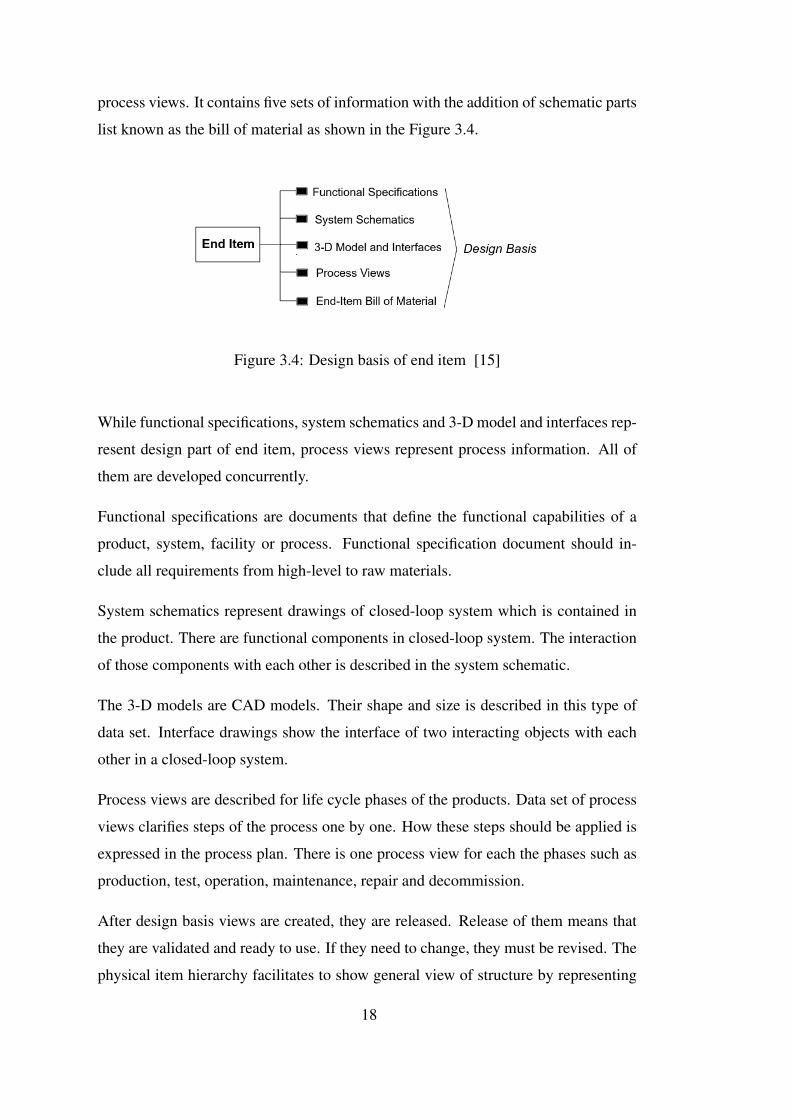
process views. It contains five sets of information with the addition of schematic parts
list known as the bill of material as shown in the Figure 3.4.
Figure 3.4: Design basis of end item [15]
While functional specifications, system schematics and 3-D model and interfaces rep-
resent design part of end item, process views represent process information. All of
them are developed concurrently.
Functional specifications are documents that define the functional capabilities of a
product, system, facility or process. Functional specification document should in-
clude all requirements from high-level to raw materials.
System schematics represent drawings of closed-loop system which is contained in
the product. There are functional components in closed-loop system. The interaction
of those components with each other is described in the system schematic.
The 3-D models are CAD models. Their shape and size is described in this type of
data set. Interface drawings show the interface of two interacting objects with each
other in a closed-loop system.
Process views are described for life cycle phases of the products. Data set of process
views clarifies steps of the process one by one. How these steps should be applied is
expressed in the process plan. There is one process view for each the phases such as
production, test, operation, maintenance, repair and decommission.
After design basis views are created, they are released. Release of them means that
they are validated and ready to use. If they need to change, they must be revised. The
physical item hierarchy facilitates to show general view of structure by representing
18
current validated documents.
3.2.2 Physical Item Hierarchy
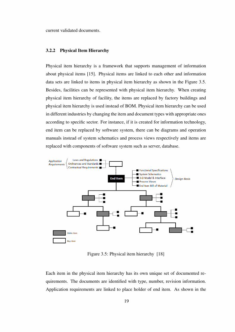
Physical item hierarchy is a framework that supports management of information
about physical items [15]. Physical items are linked to each other and information
data sets are linked to items in physical item hierarchy as shown in the Figure 3.5.
Besides, facilities can be represented with physical item hierarchy. When creating
physical item hierarchy of facility, the items are replaced by factory buildings and
physical item hierarchy is used instead of BOM. Physical item hierarchy can be used
in different industries by changing the item and document types with appropriate ones
according to specific sector. For instance, if it is created for information technology,
end item can be replaced by software system, there can be diagrams and operation
manuals instead of system schematics and process views respectively and items are
replaced with components of software system such as server, database.
Figure 3.5: Physical item hierarchy [18]
Each item in the physical item hierarchy has its own unique set of documented re-
quirements. The documents are identified with type, number, revision information.
Application requirements are linked to place holder of end item. As shown in the
19
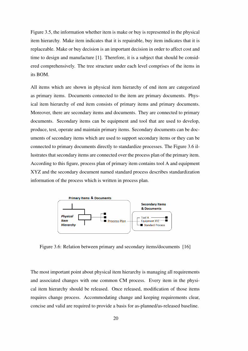
Figure 3.5, the information whether item is make or buy is represented in the physical
item hierarchy. Make item indicates that it is repairable, buy item indicates that it is
replaceable. Make or buy decision is an important decision in order to affect cost and
time to design and manufacture [1]. Therefore, it is a subject that should be consid-
ered comprehensively. The tree structure under each level comprises of the items in
its BOM.
All items which are shown in physical item hierarchy of end item are categorized
as primary items. Documents connected to the item are primary documents. Phys-
ical item hierarchy of end item consists of primary items and primary documents.
Moreover, there are secondary items and documents. They are connected to primary
documents. Secondary items can be equipment and tool that are used to develop,
produce, test, operate and maintain primary items. Secondary documents can be doc-
uments of secondary items which are used to support secondary items or they can be
connected to primary documents directly to standardize processes. The Figure 3.6 il-
lustrates that secondary items are connected over the process plan of the primary item.
According to this figure, process plan of primary item contains tool A and equipment
XYZ and the secondary document named standard process describes standardization
information of the process which is written in process plan.
Figure 3.6: Relation between primary and secondary items/documents [16]
The most important point about physical item hierarchy is managing all requirements
and associated changes with one common CM process. Every item in the physi-
cal item hierarchy should be released. Once released, modification of those items
requires change process. Accommodating change and keeping requirements clear,
concise and valid are required to provide a basis for as-planned/as-released baseline.
20
3.2.3 As-Planned/As-Released Baseline
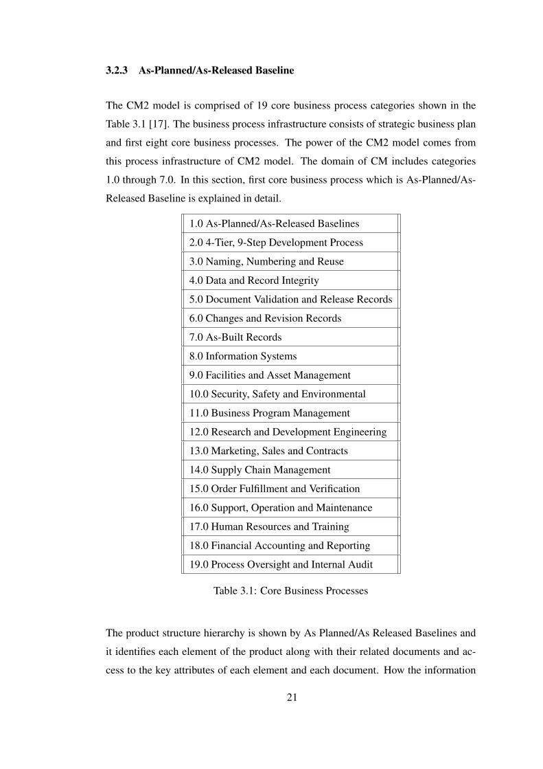
The CM2 model is comprised of 19 core business process categories shown in the
Table 3.1 [17]. The business process infrastructure consists of strategic business plan
and first eight core business processes. The power of the CM2 model comes from
this process infrastructure of CM2 model. The domain of CM includes categories
1.0 through 7.0. In this section, first core business process which is As-Planned/As-
Released Baseline is explained in detail.
1.0 As-Planned/As-Released Baselines
2.0 4-Tier, 9-Step Development Process
3.0 Naming, Numbering and Reuse
4.0 Data and Record Integrity
5.0 Document Validation and Release Records
6.0 Changes and Revision Records
7.0 As-Built Records
8.0 Information Systems
9.0 Facilities and Asset Management
10.0 Security, Safety and Environmental
11.0 Business Program Management
12.0 Research and Development Engineering
13.0 Marketing, Sales and Contracts
14.0 Supply Chain Management
15.0 Order Fulfillment and Verification
16.0 Support, Operation and Maintenance
17.0 Human Resources and Training
18.0 Financial Accounting and Reporting
19.0 Process Oversight and Internal Audit
Table 3.1: Core Business Processes
The product structure hierarchy is shown by As Planned/As Released Baselines and
it identifies each element of the product along with their related documents and ac-
cess to the key attributes of each element and each document. How the information
21
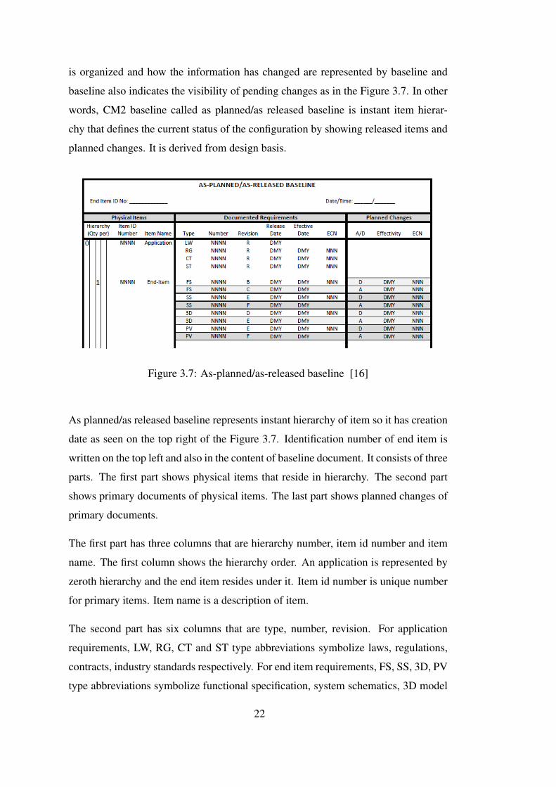
is organized and how the information has changed are represented by baseline and
baseline also indicates the visibility of pending changes as in the Figure 3.7. In other
words, CM2 baseline called as planned/as released baseline is instant item hierar-
chy that defines the current status of the configuration by showing released items and
planned changes. It is derived from design basis.
Figure 3.7: As-planned/as-released baseline [16]
As planned/as released baseline represents instant hierarchy of item so it has creation
date as seen on the top right of the Figure 3.7. Identification number of end item is
written on the top left and also in the content of baseline document. It consists of three
parts. The first part shows physical items that reside in hierarchy. The second part
shows primary documents of physical items. The last part shows planned changes of
primary documents.
The first part has three columns that are hierarchy number, item id number and item
name. The first column shows the hierarchy order. An application is represented by
zeroth hierarchy and the end item resides under it. Item id number is unique number
for primary items. Item name is a description of item.
The second part has six columns that are type, number, revision. For application
requirements, LW, RG, CT and ST type abbreviations symbolize laws, regulations,
contracts, industry standards respectively. For end item requirements, FS, SS, 3D, PV
type abbreviations symbolize functional specification, system schematics, 3D model
22
and process views as mentioned in Chapter 3.2.1. These requirements can also be
used for primary items of the end item. The second column shows id number of
primary documents. Each primary document is created, validated and released. When
it created, it has a revision information. The third column shows a revision of primary
documents. When it released, it has a release date. The fourth column shows a
release date of primary documents. It is written as DMY that symbolizes day, month,
year. The fifth column shows effective date that represents when a newly released
document is to be used. If the document has enterprise change notice (ECN), it differs
from release date. However, if the document does not have ECN, it is same with
release date. The sixth columns show ECN id number. ECN is a form that is used to
implement a change request and it includes a baseline impact matrix which includes
superseded and superseding item and documents.
The third part has three columns that are A/D, effectivity and ECN. In the first col-
umn, A/D symbolizes add or delete. According to ECN, add or delete information is
provided from the impact matrix. Delete information represents superseded item or
document and add information represents superseding item or document. In the sec-
ond column, effectivity shows an effectivity of ECN which specifies when supersed-
ing items and documents are to be used in place of superseded items and documents.
The last column indicates which ECN the change was made to.
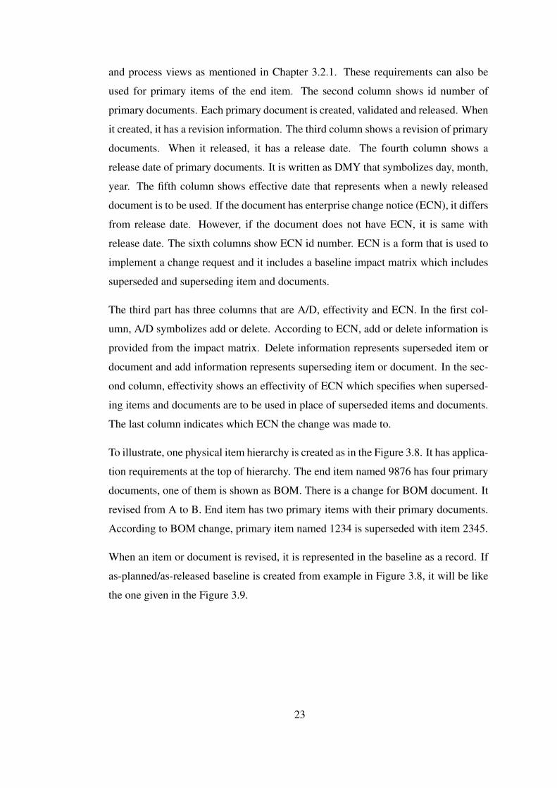
To illustrate, one physical item hierarchy is created as in the Figure 3.8. It has applica-
tion requirements at the top of hierarchy. The end item named 9876 has four primary
documents, one of them is shown as BOM. There is a change for BOM document. It
revised from A to B. End item has two primary items with their primary documents.
According to BOM change, primary item named 1234 is superseded with item 2345.
When an item or document is revised, it is represented in the baseline as a record. If
as-planned/as-released baseline is created from example in Figure 3.8, it will be like
the one given in the Figure 3.9.
23
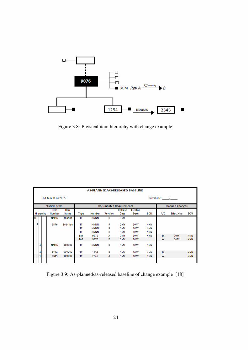
Figure 3.8: Physical item hierarchy with change example
Figure 3.9: As-planned/as-released baseline of change example [18]
24
CHAPTER 4
TOOL EXTENSION
In this chapter, the implementation of physical item hierarchy and CM2 baseline to
the PLM system are explained. Firstly, what is done as the tool extension is defined.
Secondly, how it is done is clarified. PLM system design and functionalities are
described according to the processes of the defense company.
4.1 Scope of the Tool Extension
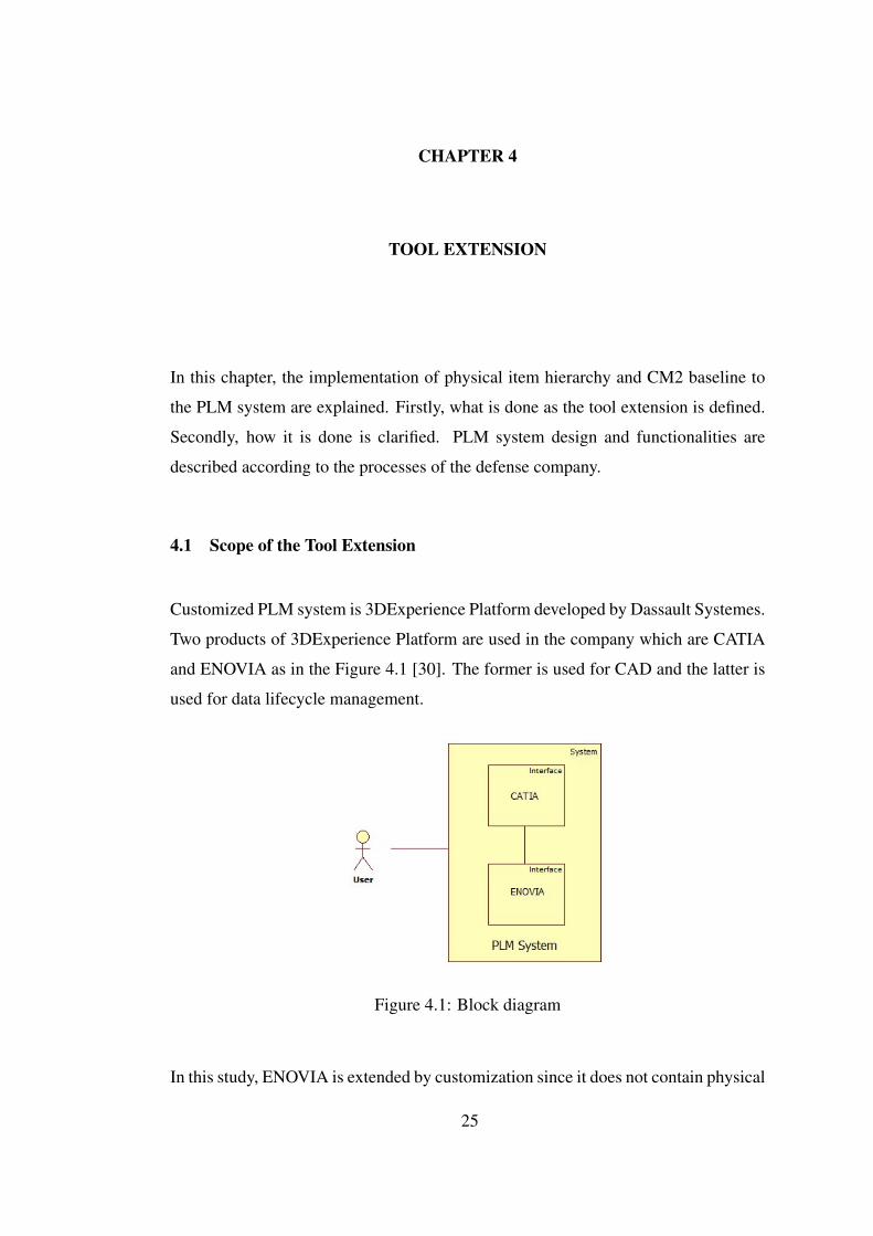
Customized PLM system is 3DExperience Platform developed by Dassault Systemes.
Two products of 3DExperience Platform are used in the company which are CATIA
and ENOVIA as in the Figure 4.1 [30]. The former is used for CAD and the latter is
used for data lifecycle management.
Figure 4.1: Block diagram
In this study, ENOVIA is extended by customization since it does not contain physical
25
item hierarchy view and baseline as clarified in CM2 methodology.
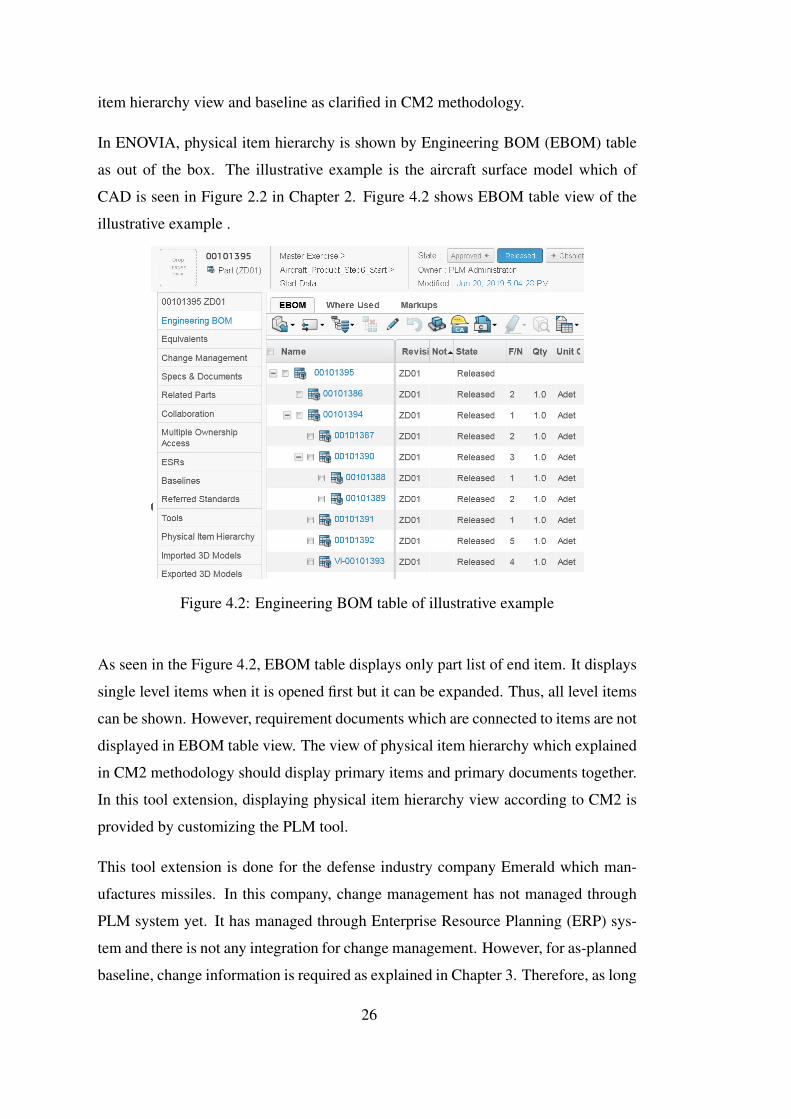
In ENOVIA, physical item hierarchy is shown by Engineering BOM (EBOM) table
as out of the box. The illustrative example is the aircraft surface model which of
CAD is seen in Figure 2.2 in Chapter 2. Figure 4.2 shows EBOM table view of the
illustrative example .
Figure 4.2: Engineering BOM table of illustrative example
As seen in the Figure 4.2, EBOM table displays only part list of end item. It displays
single level items when it is opened first but it can be expanded. Thus, all level items
can be shown. However, requirement documents which are connected to items are not
displayed in EBOM table view. The view of physical item hierarchy which explained
in CM2 methodology should display primary items and primary documents together.
In this tool extension, displaying physical item hierarchy view according to CM2 is
provided by customizing the PLM tool.
This tool extension is done for the defense industry company Emerald which man-
ufactures missiles. In this company, change management has not managed through
PLM system yet. It has managed through Enterprise Resource Planning (ERP) sys-
tem and there is not any integration for change management. However, for as-planned
baseline, change information is required as explained in Chapter 3. Therefore, as long
26
as there is not any integration between PLM system and ERP system or changes are
not managed in PLM system in Emerald, CM2 baseline cannot be implemented as
"As-Planned/As-Released Baseline" in PLM system. Consequently, it is implemented
as only "As-Released Baseline" in this study. In the road map of the company, per-
forming change management through PLM system is planned. When it is managed
from PLM system, as-released baseline will be basis for creating full baseline with
change information.
4.2 Design Details of the Tool Extension
In this section, software requirements are clarified and software design is explained by
giving information about development platform, data structure, algorithm and design
views.
4.2.1 Software Requirement Analysis
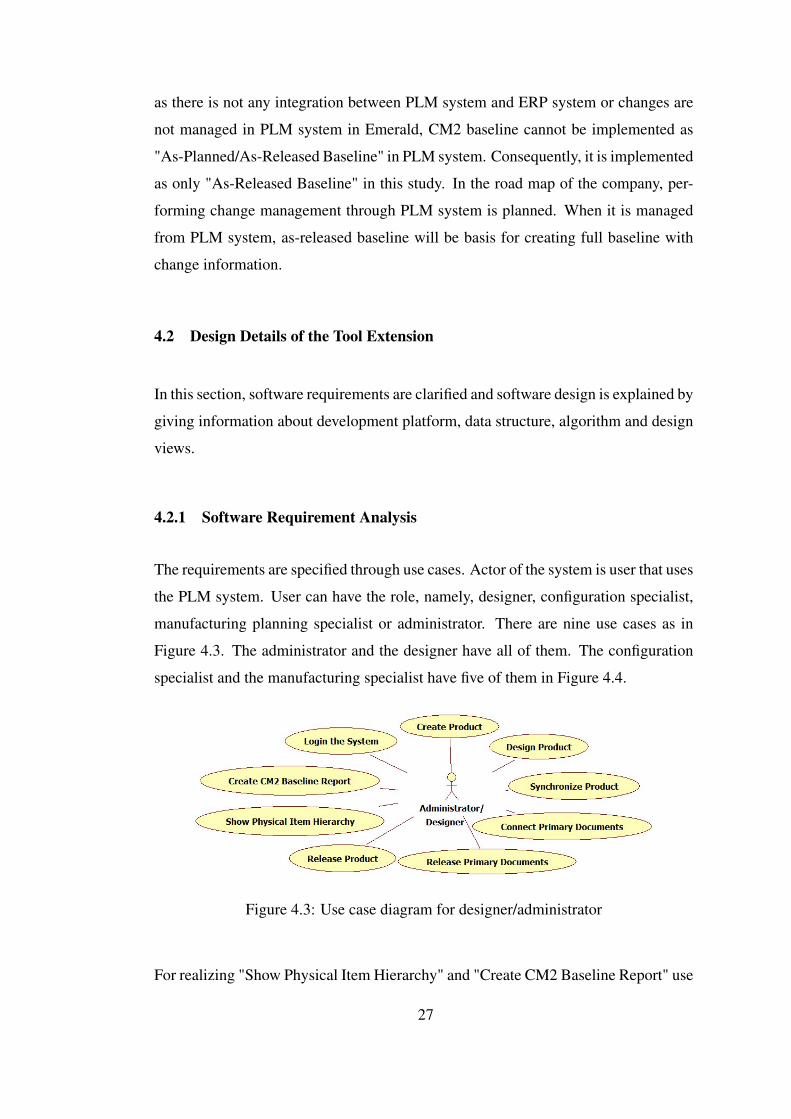
The requirements are specified through use cases. Actor of the system is user that uses
the PLM system. User can have the role, namely, designer, configuration specialist,
manufacturing planning specialist or administrator. There are nine use cases as in
Figure 4.3. The administrator and the designer have all of them. The configuration
specialist and the manufacturing specialist have five of them in Figure 4.4.
Figure 4.3: Use case diagram for designer/administrator
For realizing "Show Physical Item Hierarchy" and "Create CM2 Baseline Report" use
27
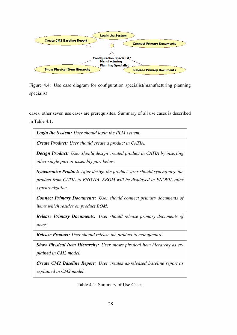
Figure 4.4: Use case diagram for configuration specialist/manufacturing planning
specialist
cases, other seven use cases are prerequisites. Summary of all use cases is described
in Table 4.1.
Login the System: User should login the PLM system.
Create Product: User should create a product in CATIA.
Design Product: User should design created product in CATIA by inserting
other single part or assembly part below.
Synchronize Product: After design the product, user should synchronize the
product from CATIA to ENOVIA. EBOM will be displayed in ENOVIA after
synchronization.
Connect Primary Documents: User should connect primary documents of
items which resides on product BOM.
Release Primary Documents: User should release primary documents of
items.
Release Product: User should release the product to manufacture.
Show Physical Item Hierarchy: User shows physical item hierarchy as ex-
plained in CM2 model.
Create CM2 Baseline Report: User creates as-released baseline report as
explained in CM2 model.
Table 4.1: Summary of Use Cases
28
For implemented use cases that are "Show Physical Item Hierarchy" and "Create CM2
Baseline Report", requirements are derived from the CMII/IPE Model [17] as follows:
1. The tool can provide visibility of current configuration.
2. The tool can display parent-to-child relationships between physical items using
BOM which are identified by type, number and revision level.
3. The tool can use bill of material to provide a fully exploded (or indented) view
of the physical(primary) items contained in each end-item product, facility or
IT system.
4. The tool can compare the primary items contained in two or more bills of ma-
terial, including fully exploded bills, and identify their similarities and differ-
ences.
5. The tool can display the linkages from each primary item to its own unique set
of design and process requirements (or primary documents)
6. The tool can support as-released product baseline formats and data fields per
the template provided in the CMII/IPE Model. Each baseline carries the same
identity as the product.
7. The tool can display the release date for each primary document.
8. The tool can provide a standardized metadata template for each type of physical
item.
9. The tool can provide a metadata template for each document type.
10. The tool can provide views of any physical item and access to any document
by "clicking" on that item or document and also provide access to the metadata
for any item or document.
11. The tool can support identification schemes for physical items which may in-
clude Commercial And Government Entity (CAGE) code which is a five-character
ID number used extensively within the federal government [9], model numbers,
item ID numbers, names and descriptions.
29
12. The tool can support identification schemes for documents which may include
document type, number, revision level and CAGE code.
13. The tool is able to identify all active applications for any primary or secondary
physical item or document.
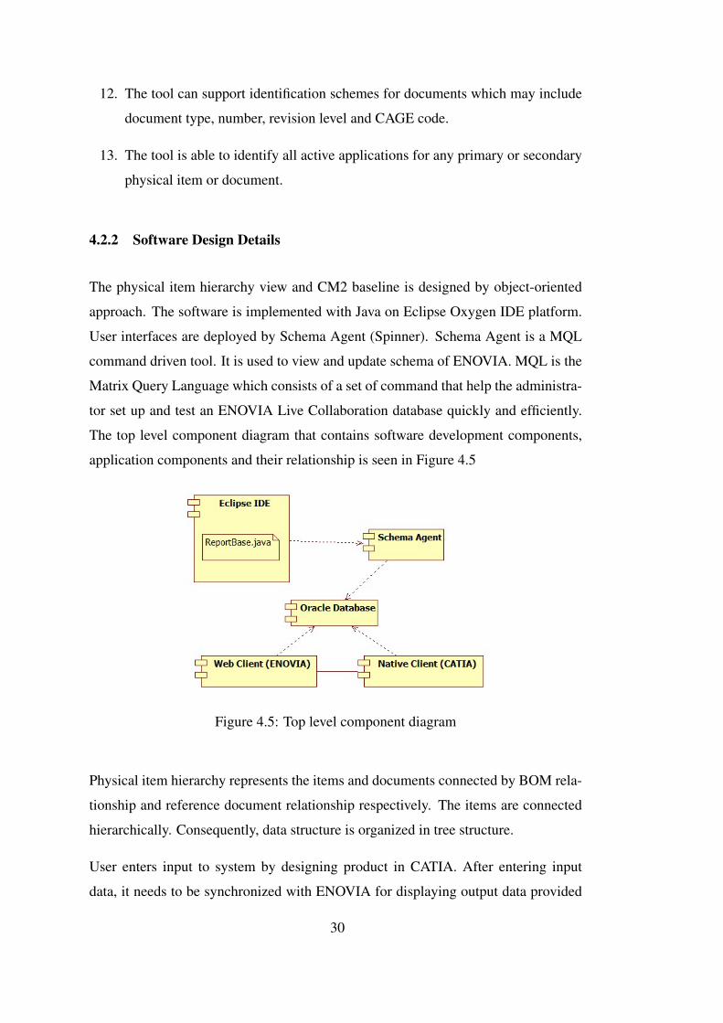
4.2.2 Software Design Details
The physical item hierarchy view and CM2 baseline is designed by object-oriented
approach. The software is implemented with Java on Eclipse Oxygen IDE platform.
User interfaces are deployed by Schema Agent (Spinner). Schema Agent is a MQL
command driven tool. It is used to view and update schema of ENOVIA. MQL is the
Matrix Query Language which consists of a set of command that help the administra-
tor set up and test an ENOVIA Live Collaboration database quickly and efficiently.
The top level component diagram that contains software development components,
application components and their relationship is seen in Figure 4.5
Figure 4.5: Top level component diagram
Physical item hierarchy represents the items and documents connected by BOM rela-
tionship and reference document relationship respectively. The items are connected
hierarchically. Consequently, data structure is organized in tree structure.
User enters input to system by designing product in CATIA. After entering input
data, it needs to be synchronized with ENOVIA for displaying output data provided
30
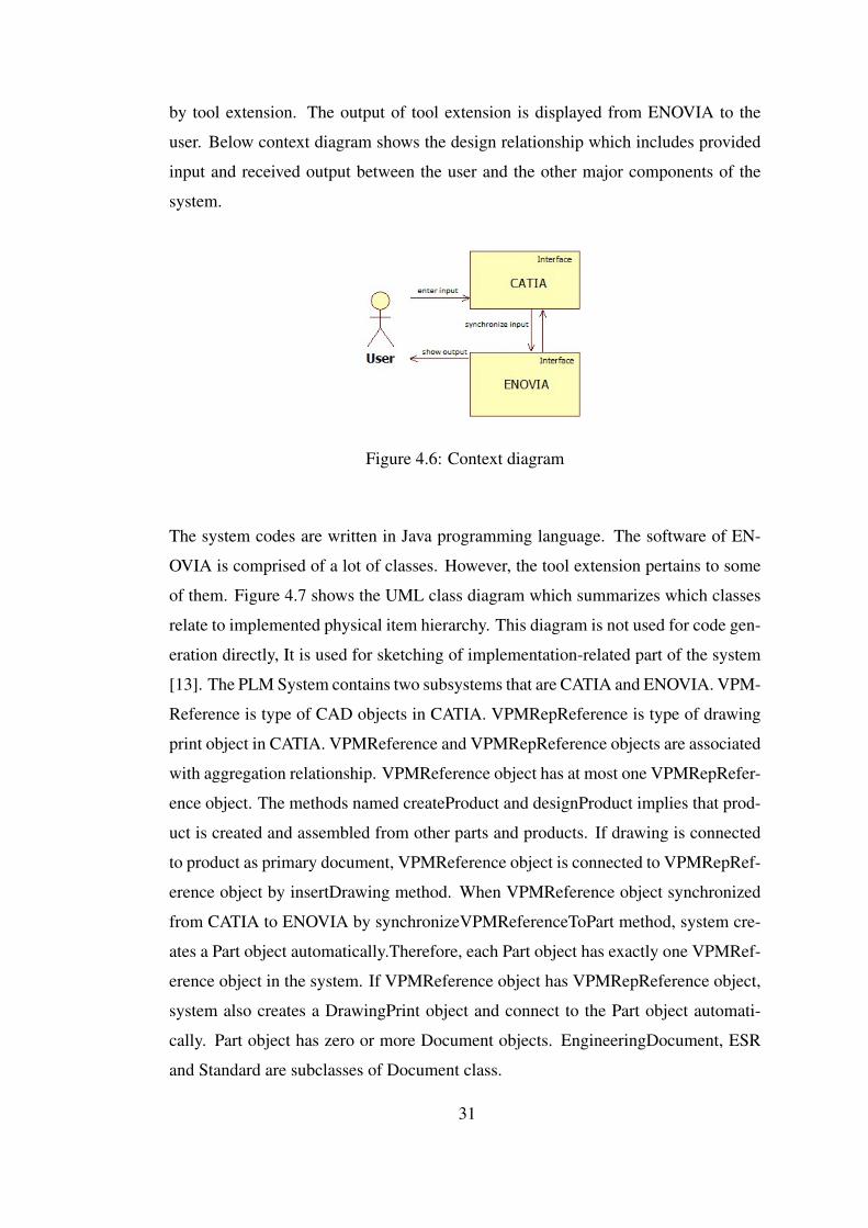
by tool extension. The output of tool extension is displayed from ENOVIA to the
user. Below context diagram shows the design relationship which includes provided
input and received output between the user and the other major components of the
system.
Figure 4.6: Context diagram
The system codes are written in Java programming language. The software of EN-
OVIA is comprised of a lot of classes. However, the tool extension pertains to some
of them. Figure 4.7 shows the UML class diagram which summarizes which classes
relate to implemented physical item hierarchy. This diagram is not used for code gen-
eration directly, It is used for sketching of implementation-related part of the system
[13]. The PLM System contains two subsystems that are CATIA and ENOVIA. VPM-
Reference is type of CAD objects in CATIA. VPMRepReference is type of drawing
print object in CATIA. VPMReference and VPMRepReference objects are associated
with aggregation relationship. VPMReference object has at most one VPMRepRefer-
ence object. The methods named createProduct and designProduct implies that prod-
uct is created and assembled from other parts and products. If drawing is connected
to product as primary document, VPMReference object is connected to VPMRepRef-
erence object by insertDrawing method. When VPMReference object synchronized
from CATIA to ENOVIA by synchronizeVPMReferenceToPart method, system cre-
ates a Part object automatically.Therefore, each Part object has exactly one VPMRef-
erence object in the system. If VPMReference object has VPMRepReference object,
system also creates a DrawingPrint object and connect to the Part object automati-
cally. Part object has zero or more Document objects. EngineeringDocument, ESR
and Standard are subclasses of Document class.
31
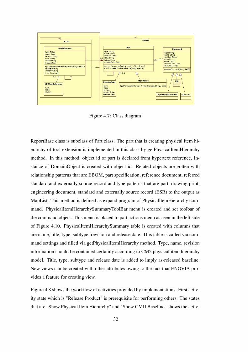
Figure 4.7: Class diagram
ReportBase class is subclass of Part class. The part that is creating physical item hi-
erarchy of tool extension is implemented in this class by getPhysicalItemHierarchy
method. In this method, object id of part is declared from hypertext reference, In-
stance of DomainObject is created with object id. Related objects are gotten with
relationship patterns that are EBOM, part specification, reference document, referred
standard and externally source record and type patterns that are part, drawing print,
engineering document, standard and externally source record (ESR) to the output as
MapList. This method is defined as expand program of PhysicalItemHierarchy com-
mand. PhysicalItemHierarchySummaryToolBar menu is created and set toolbar of
the command object. This menu is placed to part actions menu as seen in the left side
of Figure 4.10. PhysicalItemHierarchySummary table is created with columns that
are name, title, type, subtype, revision and release date. This table is called via com-
mand settings and filled via getPhysicalItemHierarchy method. Type, name, revision
information should be contained certainly according to CM2 physical item hierarchy
model. Title, type, subtype and release date is added to imply as-released baseline.
New views can be created with other attributes owing to the fact that ENOVIA pro-
vides a feature for creating view.
Figure 4.8 shows the workflow of activities provided by implementations. First activ-
ity state which is "Release Product" is prerequisite for performing others. The states
that are "Show Physical Item Hierarchy" and "Show CMII Baseline" shows the activ-
32
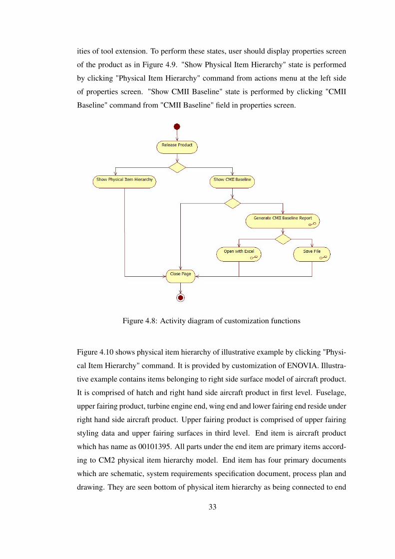
ities of tool extension. To perform these states, user should display properties screen
of the product as in Figure 4.9. "Show Physical Item Hierarchy" state is performed
by clicking "Physical Item Hierarchy" command from actions menu at the left side
of properties screen. "Show CMII Baseline" state is performed by clicking "CMII
Baseline" command from "CMII Baseline" field in properties screen.
Figure 4.8: Activity diagram of customization functions
Figure 4.10 shows physical item hierarchy of illustrative example by clicking "Physi-
cal Item Hierarchy" command. It is provided by customization of ENOVIA. Illustra-
tive example contains items belonging to right side surface model of aircraft product.
It is comprised of hatch and right hand side aircraft product in first level. Fuselage,
upper fairing product, turbine engine end, wing end and lower fairing end reside under
right hand side aircraft product. Upper fairing product is comprised of upper fairing
styling data and upper fairing surfaces in third level. End item is aircraft product
which has name as 00101395. All parts under the end item are primary items accord-
ing to CM2 physical item hierarchy model. End item has four primary documents
which are schematic, system requirements specification document, process plan and
drawing. They are seen bottom of physical item hierarchy as being connected to end
33
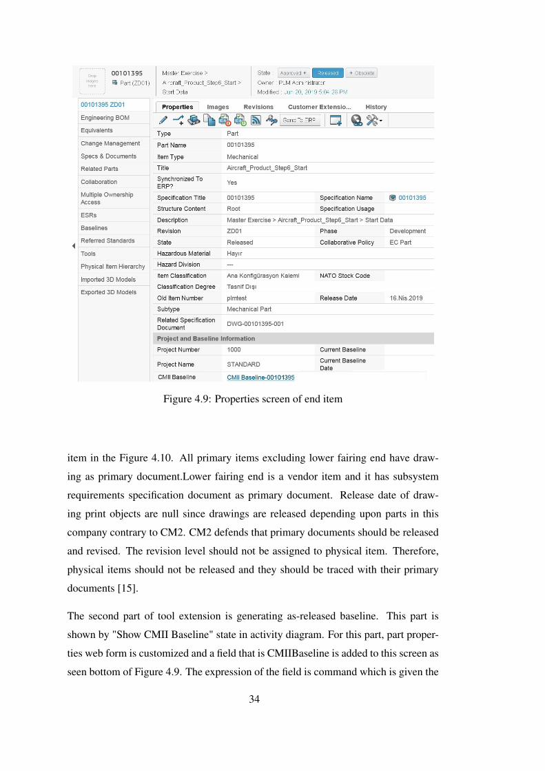
Figure 4.9: Properties screen of end item
item in the Figure 4.10. All primary items excluding lower fairing end have draw-
ing as primary document.Lower fairing end is a vendor item and it has subsystem
requirements specification document as primary document. Release date of draw-
ing print objects are null since drawings are released depending upon parts in this
company contrary to CM2. CM2 defends that primary documents should be released
and revised. The revision level should not be assigned to physical item. Therefore,
physical items should not be released and they should be traced with their primary
documents [15].
The second part of tool extension is generating as-released baseline. This part is
shown by "Show CMII Baseline" state in activity diagram. For this part, part proper-
ties web form is customized and a field that is CMIIBaseline is added to this screen as
seen bottom of Figure 4.9. The expression of the field is command which is given the
34
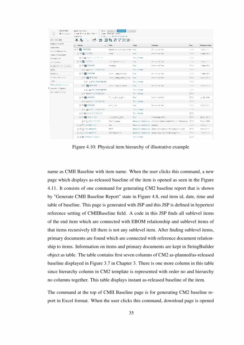
Figure 4.10: Physical item hierarchy of illustrative example
name as CMII Baseline with item name. When the user clicks this command, a new
page which displays as-released baseline of the item is opened as seen in the Figure
4.11. It consists of one command for generating CM2 baseline report that is shown
by "Generate CMII Baseline Report" state in Figure 4.8, end item id, date, time and
table of baseline. This page is generated with JSP and this JSP is defined in hypertext
reference setting of CMIIBaseline field. A code in this JSP finds all sublevel items
of the end item which are connected with EBOM relationship and sublevel items of
that items recursively till there is not any sublevel item. After finding sublevel items,
primary documents are found which are connected with reference document relation-
ship to items. Information on items and primary documents are kept in StringBuilder
object as table. The table contains first seven columns of CM2 as-planned/as-released
baseline displayed in Figure 3.7 in Chapter 3. There is one more column in this table
since hierarchy column in CM2 template is represented with order no and hierarchy
no columns together. This table displays instant as-released baseline of the item.
The command at the top of CMII Baseline page is for generating CM2 baseline re-
port in Excel format. When the user clicks this command, download page is opened
35
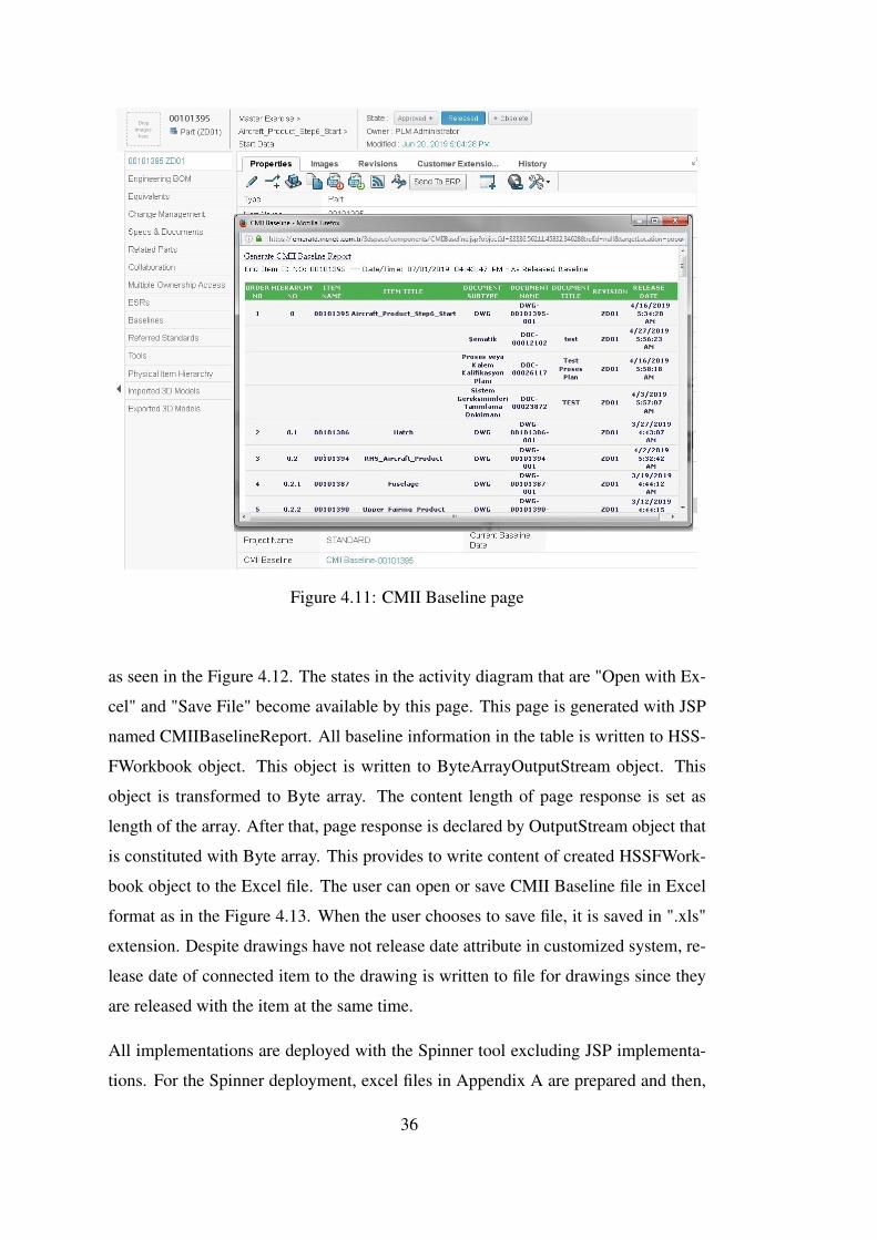
Figure 4.11: CMII Baseline page
as seen in the Figure 4.12. The states in the activity diagram that are "Open with Ex-
cel" and "Save File" become available by this page. This page is generated with JSP
named CMIIBaselineReport. All baseline information in the table is written to HSS-
FWorkbook object. This object is written to ByteArrayOutputStream object. This
object is transformed to Byte array. The content length of page response is set as
length of the array. After that, page response is declared by OutputStream object that
is constituted with Byte array. This provides to write content of created HSSFWork-
book object to the Excel file. The user can open or save CMII Baseline file in Excel
format as in the Figure 4.13. When the user chooses to save file, it is saved in ".xls"
extension. Despite drawings have not release date attribute in customized system, re-
lease date of connected item to the drawing is written to file for drawings since they
are released with the item at the same time.
All implementations are deployed with the Spinner tool excluding JSP implementa-
tions. For the Spinner deployment, excel files in Appendix A are prepared and then,
36
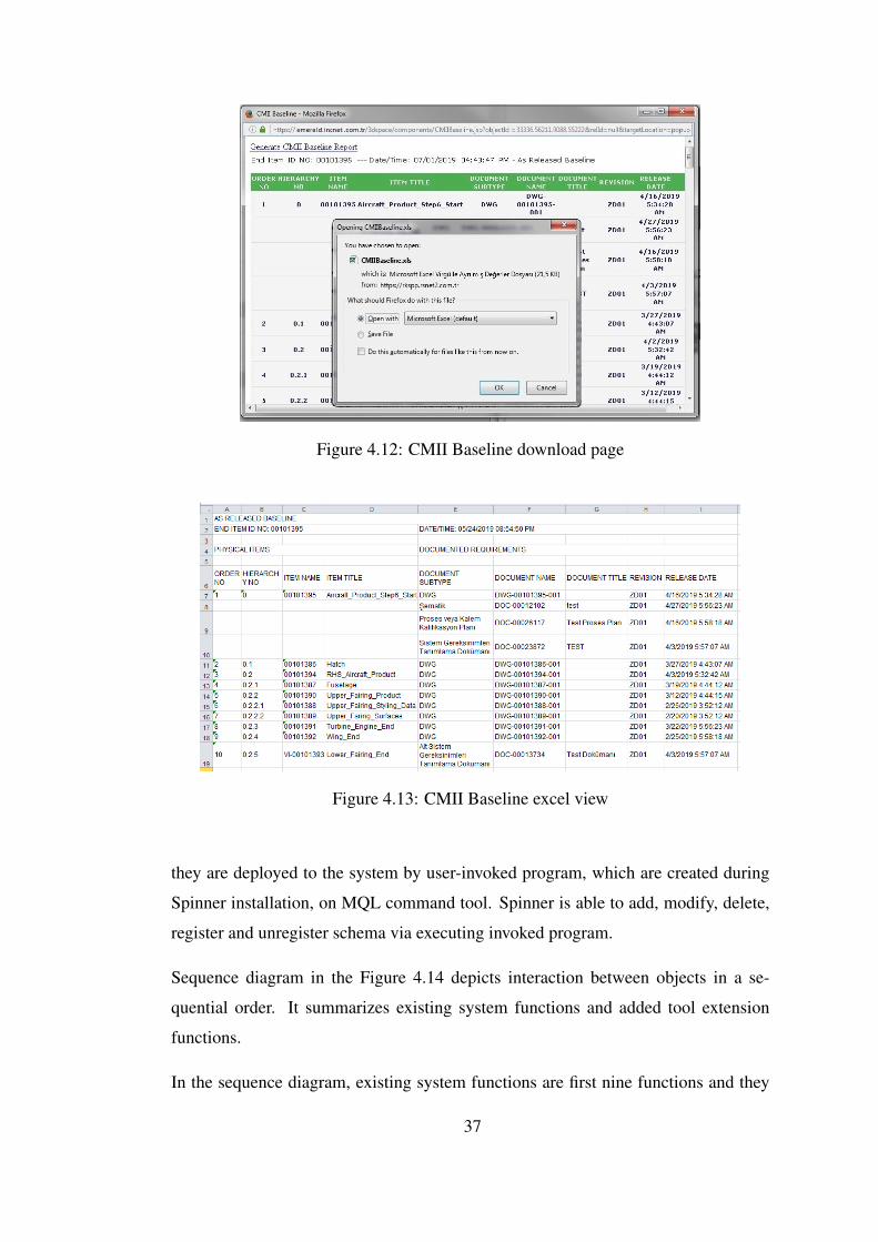
Figure 4.12: CMII Baseline download page
Figure 4.13: CMII Baseline excel view
they are deployed to the system by user-invoked program, which are created during
Spinner installation, on MQL command tool. Spinner is able to add, modify, delete,
register and unregister schema via executing invoked program.
Sequence diagram in the Figure 4.14 depicts interaction between objects in a se-
quential order. It summarizes existing system functions and added tool extension
functions.
In the sequence diagram, existing system functions are first nine functions and they
37
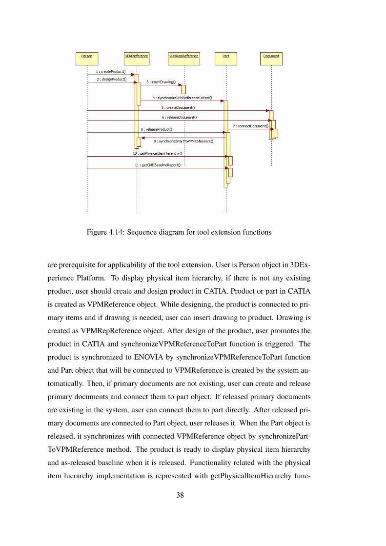
Figure 4.14: Sequence diagram for tool extension functions
are prerequisite for applicability of the tool extension. User is Person object in 3DEx-
perience Platform. To display physical item hierarchy, if there is not any existing
product, user should create and design product in CATIA. Product or part in CATIA
is created as VPMReference object. While designing, the product is connected to pri-
mary items and if drawing is needed, user can insert drawing to product. Drawing is
created as VPMRepReference object. After design of the product, user promotes the
product in CATIA and synchronizeVPMReferenceToPart function is triggered. The
product is synchronized to ENOVIA by synchronizeVPMReferenceToPart function
and Part object that will be connected to VPMReference is created by the system au-
tomatically. Then, if primary documents are not existing, user can create and release
primary documents and connect them to part object. If released primary documents
are existing in the system, user can connect them to part directly. After released pri-
mary documents are connected to Part object, user releases it. When the Part object is
released, it synchronizes with connected VPMReference object by synchronizePart-
ToVPMReference method. The product is ready to display physical item hierarchy
and as-released baseline when it is released. Functionality related with the physical
item hierarchy implementation is represented with getPhysicalItemHierarchy func-
38
tion and functionality related with the CM2 baseline implementation is represented
with getCMIIBaselineReport function. After one product is released by providing
prerequisites in the PLM System, these functionalities can be used by the users.
To sum up, tool extension comprises of two parts which are displaying physical item
hierarchy in ENOVIA and generating CM2 baseline from ENOVIA. The details and
steps of development is explained by UML diagrams and UI views. CM2 baseline im-
plementation does not totally involve as-planned/as-released baseline as in the CM2
methodology. It involves only as-released part of CM2 baseline. However, there is
a possibility to modify the implementation when the company begins to use change
management applications in 3DExperience Platform. All implementations is applied
to the custom system. Therefore, the scenarios and the system usage is special to the
company and they are not same with OOTB version of 3DExperience Platform.
39

40
CHAPTER 5
CASE STUDY FROM EMERALD COMPANY
In this chapter, physical item hierarchy of a real product from defense industry is
analyzed as a case study. The telemetry system which is a subsystem of a missile is
considered as a product. The utilization of customization explained in Chapter 4 is
exemplified by this product. Functional validation of the implementation is provided
and its usability test is performed.
5.1 Telemetry System
A telemetry system is a subsystem of a missile which is comprised of transmitter,
antenna, battery, encoder, sensors and cable network. Telemetry systems are often
used for diagnostics in artillery systems where unused space can be found in the
ogive or payload compartments or by the simple replacement of a nose-located fuze
[8]. In the missile company, the warhead is replaced with telemetry system and it
is used for flight testing. The book entitled Telemetry Systems Engineering shows
telemetry system for the flight testing of a missile as in Figure 5.1 [14].
In the missile company, telemetry system samples data which is calculated by an
algorithm of navigation, guidance and autopilot and data which is acquired from the
sensors in seeker, inertial measurement unit, control drive system, power supply or
power management unit with specific time intervals and sends to ground systems.It
is not used in main configuration. It is used in test configuration. The sub-parts of
this product vary according to test objectives. For example, if vibration test will be
performed, it contains vibration sensor. Also, it can contain other type of sensors for
another tests.
41
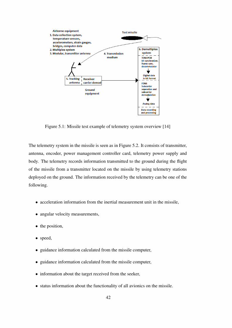
Figure 5.1: Missile test example of telemetry system overview [14]
The telemetry system in the missile is seen as in Figure 5.2. It consists of transmitter,
antenna, encoder, power management controller card, telemetry power supply and
body. The telemetry records information transmitted to the ground during the flight
of the missile from a transmitter located on the missile by using telemetry stations
deployed on the ground. The information received by the telemetry can be one of the
following.
• acceleration information from the inertial measurement unit in the missile,
• angular velocity measurements,
• the position,
• speed,
• guidance information calculated from the missile computer,
• guidance information calculated from the missile computer,
• information about the target received from the seeker,
• status information about the functionality of all avionics on the missile.
42
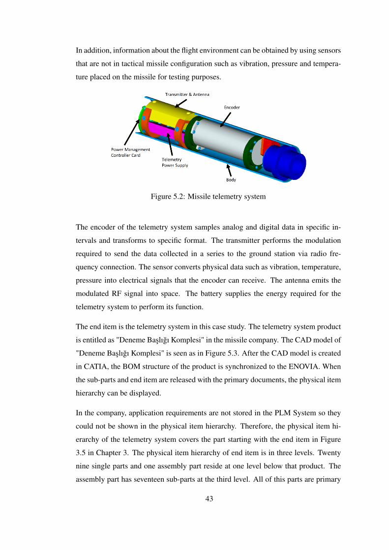
In addition, information about the flight environment can be obtained by using sensors
that are not in tactical missile configuration such as vibration, pressure and tempera-
ture placed on the missile for testing purposes.
Figure 5.2: Missile telemetry system
The encoder of the telemetry system samples analog and digital data in specific in-
tervals and transforms to specific format. The transmitter performs the modulation
required to send the data collected in a series to the ground station via radio fre-
quency connection. The sensor converts physical data such as vibration, temperature,
pressure into electrical signals that the encoder can receive. The antenna emits the
modulated RF signal into space. The battery supplies the energy required for the
telemetry system to perform its function.
The end item is the telemetry system in this case study. The telemetry system product
is entitled as "Deneme Baslıgı Komplesi" in the missile company. The CAD model of
"Deneme Baslıgı Komplesi" is seen as in Figure 5.3. After the CAD model is created
in CATIA, the BOM structure of the product is synchronized to the ENOVIA. When
the sub-parts and end item are released with the primary documents, the physical item
hierarchy can be displayed.
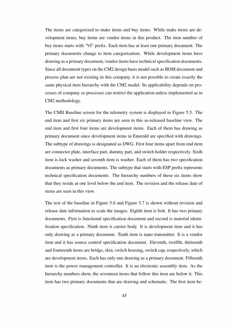
In the company, application requirements are not stored in the PLM System so they
could not be shown in the physical item hierarchy. Therefore, the physical item hi-
erarchy of the telemetry system covers the part starting with the end item in Figure
3.5 in Chapter 3. The physical item hierarchy of end item is in three levels. Twenty
nine single parts and one assembly part reside at one level below that product. The
assembly part has seventeen sub-parts at the third level. All of this parts are primary
43
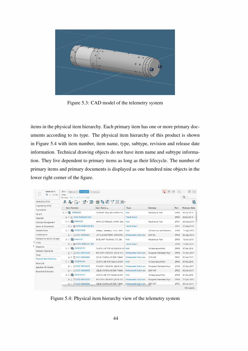
Figure 5.3: CAD model of the telemetry system
items in the physical item hierarchy. Each primary item has one or more primary doc-
uments according to its type. The physical item hierarchy of this product is shown
in Figure 5.4 with item number, item name, type, subtype, revision and release date
information. Technical drawing objects do not have item name and subtype informa-
tion. They live dependent to primary items as long as their lifecycle. The number of
primary items and primary documents is displayed as one hundred nine objects in the
lower right corner of the figure.
Figure 5.4: Physical item hierarchy view of the telemetry system
44
The items are categorized to make items and buy items. While make items are de-
velopment items, buy items are vendor items in this product. The item number of
buy items starts with "VI" prefix. Each item has at least one primary document. The
primary documents change to item categorization. While development items have
drawing as a primary document, vendor items have technical specification documents.
Since all document types on the CM2 design basis model such as BOM document and
process plan are not existing in this company, it is not possible to create exactly the
same physical item hierarchy with the CM2 model. Its applicability depends on pro-
cesses of company so processes can restrict the application unless implemented as in
CM2 methodology.
The CMII Baseline screen for the telemetry system is displayed in Figure 5.5. The
end item and first six primary items are seen in this as-released baseline view. The
end item and first four items are development items. Each of them has drawing as
primary document since development items in Emerald are specified with drawings.
The subtype of drawings is designated as DWG. First four items apart from end item
are connector plate, interface part, dummy part, and switch holder respectively. Sixth
item is lock washer and seventh item is washer. Each of them has two specification
documents as primary documents. The subtype that starts with ESP prefix represents
technical specification documents. The hierarchy numbers of these six items show
that they reside at one level below the end item. The revision and the release date of
items are seen in this view.
The rest of the baseline in Figure 5.6 and Figure 5.7 is shown without revision and
release date information to scale the images. Eighth item is bolt. It has two primary
documents. First is functional specification document and second is material identi-
fication specification. Ninth item is carrier body. It is development item and it has
only drawing as a primary document. Tenth item is nano transmitter. It is a vendor
item and it has source control specification document. Eleventh, twelfth, thirteenth
and fourteenth items are bridge, skin, switch housing, switch cap, respectively, which
are development items. Each has only one drawing as a primary document. Fifteenth
item is the power management controller. It is an electronic assembly item. As the
hierarchy numbers show, the seventeen items that follow this item are below it. This
item has two primary documents that are drawing and schematic. The first item be-
45
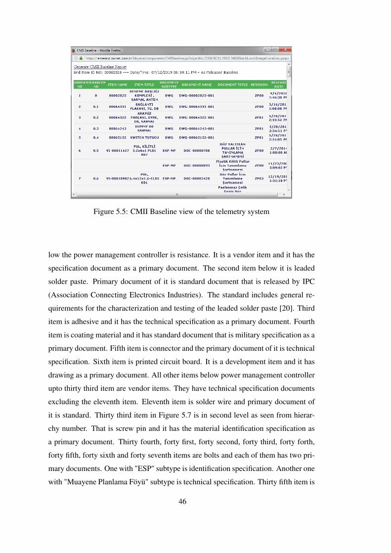
Figure 5.5: CMII Baseline view of the telemetry system
low the power management controller is resistance. It is a vendor item and it has the
specification document as a primary document. The second item below it is leaded
solder paste. Primary document of it is standard document that is released by IPC
(Association Connecting Electronics Industries). The standard includes general re-
quirements for the characterization and testing of the leaded solder paste [20]. Third
item is adhesive and it has the technical specification as a primary document. Fourth
item is coating material and it has standard document that is military specification as a
primary document. Fifth item is connector and the primary document of it is technical
specification. Sixth item is printed circuit board. It is a development item and it has
drawing as a primary document. All other items below power management controller
upto thirty third item are vendor items. They have technical specification documents
excluding the eleventh item. Eleventh item is solder wire and primary document of
it is standard. Thirty third item in Figure 5.7 is in second level as seen from hierar-
chy number. That is screw pin and it has the material identification specification as
a primary document. Thirty fourth, forty first, forty second, forty third, forty forth,
forty fifth, forty sixth and forty seventh items are bolts and each of them has two pri-
mary documents. One with "ESP" subtype is identification specification. Another one
with "Muayene Planlama Föyü" subtype is technical specification. Thirty fifth item is
46
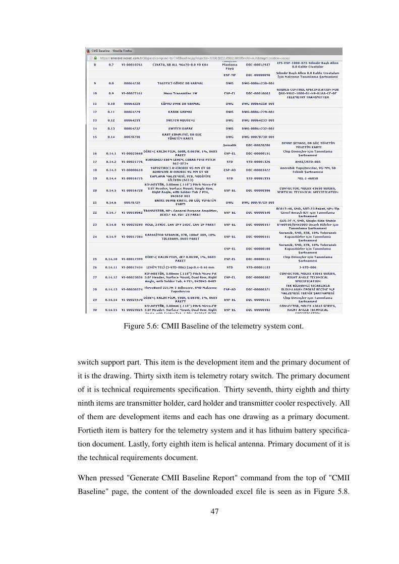
Figure 5.6: CMII Baseline of the telemetry system cont.
switch support part. This item is the development item and the primary document of
it is the drawing. Thirty sixth item is telemetry rotary switch. The primary document
of it is technical requirements specification. Thirty seventh, thirty eighth and thirty
ninth items are transmitter holder, card holder and transmitter cooler respectively. All
of them are development items and each has one drawing as a primary document.
Fortieth item is battery for the telemetry system and it has lithuim battery specifica-
tion document. Lastly, forty eighth item is helical antenna. Primary document of it is
the technical requirements document.
When pressed "Generate CMII Baseline Report" command from the top of "CMII
Baseline" page, the content of the downloaded excel file is seen as in Figure 5.8.
47
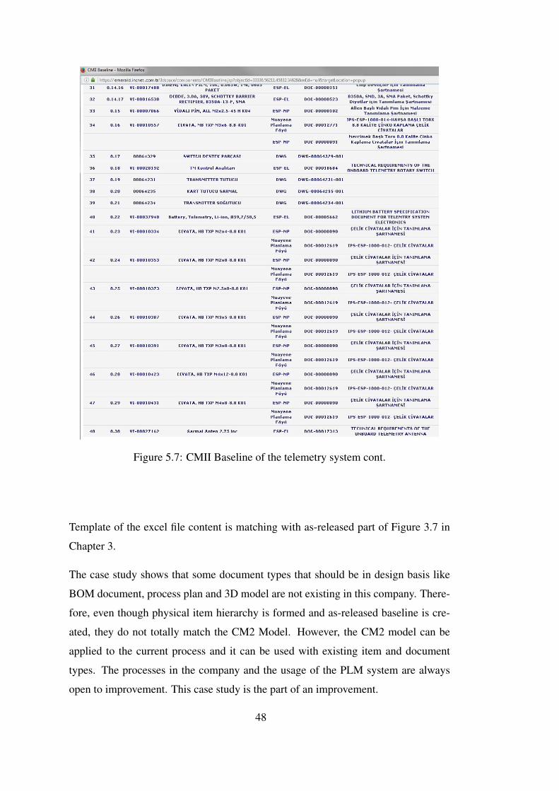
Figure 5.7: CMII Baseline of the telemetry system cont.
Template of the excel file content is matching with as-released part of Figure 3.7 in
Chapter 3.
The case study shows that some document types that should be in design basis like
BOM document, process plan and 3D model are not existing in this company. There-
fore, even though physical item hierarchy is formed and as-released baseline is cre-
ated, they do not totally match the CM2 Model. However, the CM2 model can be
applied to the current process and it can be used with existing item and document
types. The processes in the company and the usage of the PLM system are always
open to improvement. This case study is the part of an improvement.
48
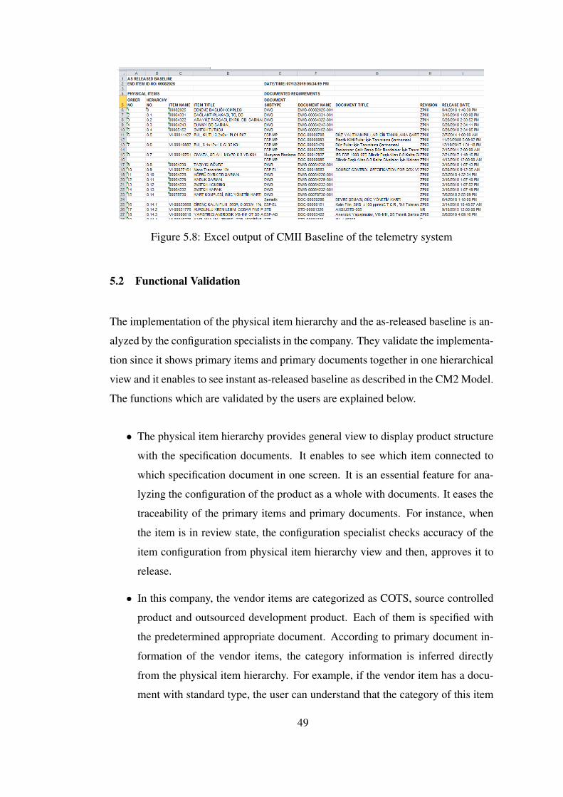
Figure 5.8: Excel output of CMII Baseline of the telemetry system
5.2 Functional Validation
The implementation of the physical item hierarchy and the as-released baseline is an-
alyzed by the configuration specialists in the company. They validate the implementa-
tion since it shows primary items and primary documents together in one hierarchical
view and it enables to see instant as-released baseline as described in the CM2 Model.
The functions which are validated by the users are explained below.
• The physical item hierarchy provides general view to display product structure
with the specification documents. It enables to see which item connected to
which specification document in one screen. It is an essential feature for ana-
lyzing the configuration of the product as a whole with documents. It eases the
traceability of the primary items and primary documents. For instance, when
the item is in review state, the configuration specialist checks accuracy of the
item configuration from physical item hierarchy view and then, approves it to
release.
• In this company, the vendor items are categorized as COTS, source controlled
product and outsourced development product. Each of them is specified with
the predetermined appropriate document. According to primary document in-
formation of the vendor items, the category information is inferred directly
from the physical item hierarchy. For example, if the vendor item has a docu-
ment with standard type, the user can understand that the category of this item
49
is COTS.
• If any item in the physical item hierarchy has the test result report as a pri-
mary document, if the item changes, the information that tests need to be re-
performed and the document must be updated can be directly inferred from
the physical item hierarchy. For example, the user knows that the range of the
missile changes. When the user displays physical item hierarchy of the missile
and sees that the missile has the test document, s/he deduces that the change
affects the test results so tests related to the range should be re-performed and
test document should be revised.
• When any change is requested for the product, the items included in the BOM
of the product and the documents defining these items are examined one by one
and the impact analysis of the change is performed. Owing to CM2 Baseline,
affected items and documents is analyzed easily from single view by using hi-
erarchical data. For example, the third level item in product BOM is planned to
change. User analyzes primary documents of the item and upper level primary
items and primary documents from CM2 Baseline.
• The technical data package delivered to the customer for consists of BOM infor-
mation of the product and documents describing the items in the BOM. "Gener-
ate CMII Baseline" functionality of the implementation generates the package
content so that the effort required for technical data package preparation is min-
imized. For instance, when the customer wants to have technical data package
at the end of the project, all data required in the technical data package is pre-
pared quickly with the help of CM2 baseline and physical item hierarchy and
delivered to the customer.
• The primary document types in the physical item hierarchy are examined to
determine whether the primary items can be reused in another product. For
example, if the product to be produced is similar to an existing product, it is
decided according to the information obtained from the primary documents
which parts should be reused. In the light of this information, product structure
is created and detailed design is done.
50
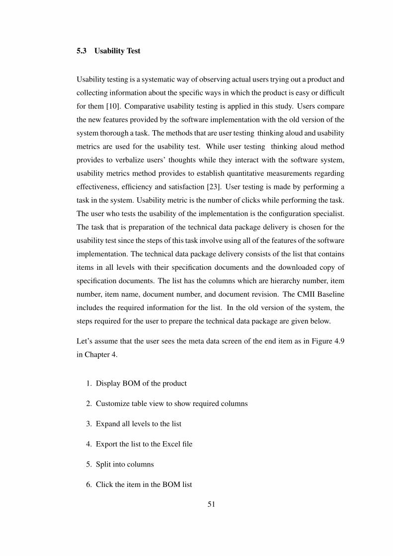
5.3 Usability Test
Usability testing is a systematic way of observing actual users trying out a product and
collecting information about the specific ways in which the product is easy or difficult
for them [10]. Comparative usability testing is applied in this study. Users compare
the new features provided by the software implementation with the old version of the
system thorough a task. The methods that are user testing thinking aloud and usability
metrics are used for the usability test. While user testing thinking aloud method
provides to verbalize users’ thoughts while they interact with the software system,
usability metrics method provides to establish quantitative measurements regarding
effectiveness, efficiency and satisfaction [23]. User testing is made by performing a
task in the system. Usability metric is the number of clicks while performing the task.
The user who tests the usability of the implementation is the configuration specialist.
The task that is preparation of the technical data package delivery is chosen for the
usability test since the steps of this task involve using all of the features of the software
implementation. The technical data package delivery consists of the list that contains
items in all levels with their specification documents and the downloaded copy of
specification documents. The list has the columns which are hierarchy number, item
number, item name, document number, and document revision. The CMII Baseline
includes the required information for the list. In the old version of the system, the
steps required for the user to prepare the technical data package are given below.
Let’s assume that the user sees the meta data screen of the end item as in Figure 4.9
in Chapter 4.
1. Display BOM of the product
2. Customize table view to show required columns
3. Expand all levels to the list
4. Export the list to the Excel file
5. Split into columns
6. Click the item in the BOM list
51
7. Find the related specification document from "Specs and Documents", "ESRs"
or "Referred Standards" menu which are seen in actions menu in the left side
of Figure 4.9.
8. Click the specification document
9. Download the document
10. Back to the BOM list
11. Repeat the steps 6-10 for all items in the BOM list
Each step above corresponds to seperate click in the system. In the new customized
system, the user clicks the CMII Baseline command. S/he clicks the "Generate CMII
Baseline" command and saves the Excel file. In this way, the number of clicks for the
first five steps decreases to three clicks. For finding specification document, the user
directly clicks "Physical Item Hierarchy" command from the actions menu. The table
of Physical Item Hierarchy directly shows the specification documents with the items
together so the user does not need to search them from the actions menu in metadata
screen of the item as mentioned in the steps 6 and 7. Then, the number of clicks for
downloading document decreases from five to three. Since the document download
is done for each item, the number of clicks for document download is multiplied by
the number of items in the physical item hierarchy. Thus, the reduction in the number
of clicks is the number of items multiplied by two. When x equals the total reduction
in clicks and y equals the number of items in the physical item hierarchy, the total
reduction in the number of clicks is calculated by equation 51. The equation shows
that as the number of items in the physical item hierarchy increases, reduction in
clicks increases. Thus, the task is completed more quickly by saving time.
x = 2 + 2y (51)
At the end of the usability test, while the reduction in clicks is the result of the usabil-
ity metrics method, the user’s opinion about saving on time and facilitating the user’s
work is the result of the user testing - thinking aloud method.
52
CHAPTER 6
CONCLUSION
The study of the CMII-based physical item hierarchy implementation in a PLM sys-
tem is concluded in this chapter. Possible future improvements related to this study
are described.
6.1 Achievements
The notion of the product lifecycle covers the stages of the product from key concept
to disposal. The product lifecycle is managed through the software tool named PLM
system. PLM system is essential for the companies due to track all process applied to
the product in one system. The PLM system is essential tool for the digitalization of
the company processes.
The one important field where PLM system is used is product configuration man-
agement. CM is the process for creating, analyzing, and tracking the physical and
functional features of the product according to the requirements, operational stan-
dards and processes. Product structure is a breakdown structure of the objects which
constitutes the product. Analyzing product structure is one of the tasks of configura-
tion specialists.
CM2 is an enterprise standard that describes the processes of configuration manage-
ment by the operational standards. In this thesis, CM2-based product structure model,
namely, physical item hierarchy is explained. The physical item hierarchy is a tree
structured model of the product which shows the connected parts and released speci-
fication data sets. Physical item hierarchy is used for creating product baseline named
53
CM2 baseline. CM2 baseline shows the as planned/as released baseline of the prod-
uct. All requirements and associated changes are managed with it.
The physical item hierarchy is implemented to the PLM system and as released base-
line of the items is generated from the physical item hierarchy in the defense company
using customized PLM system. Although the process of the company’s configuration
management is not totally the same with the CM2 model, the implementation is done
in the most similar way.
As a case study, the physical item hierarchy of a telemetry system is analyzed. The
primary items and primary documents of the product are described. The case study
shows that some primary documents that are mentioned in CM2 model are not exist-
ing since the process in company is not compatible with CM2 model. However, if the
company adapts its processes to the CM2 model, the physical item hierarchy can be
used more effectively and process excellence for product structuring can be achieved.
6.2 Future Work
As explained in Chapter 3, the CM2 baseline is comprised of two parts, namely, as
planned and as released. As planned baseline is involved in change management.
Since the change management is not performed in the PLM system, as planned base-
line is not implemented in this study. Therefore, change can be managed in the PLM
system and the as planned baseline implementation can be done in the future.
54
REFERENCES
[1] E. Anderson and G. Parker. The effect of learning on the make/buy decision.
Production and Operation Management, 11, 09 2002.
[2] Configuration management standard ansi/eia-649b. Standard, American Na-
tional Standards Institute, Washington, D.C., Apr. 2011.
[3] L. R. Antoine Brière-Côté and A. Desrochers. Adaptive generic product struc-
ture modelling for design reuse in engineer-to-order products. Computers in
Industry, 61(1):53–65, 2010.
[4] Y. Asiedu and P. Gu. Product life cycle cost analysis: State of the art review.
International Journal of Production Research, 36(4):883–908, 1998.
[5] S. Boschert and R. Rosen. Digital twin-the simulation aspect. In Mechatronic
Futures: Challenges and Solutions for Mechatronic Systems and their Design-
ers, pages 59–74. 06 2016.
[6] C. Boton, L. Rivest, D. Forgues, and J. Jupp. Comparing plm and bim from
the product structure standpoint. In Product Lifecycle Management for Digi-
tal Transformation of Industries: 13th IFIP WG 5.1 International Conference,
pages 443–453, South Carolina,Columbia, 2016. The International Federation
for Information Processing.
[7] I. Crnkovic, U. Asklund, and A. Persson. Implementing and Integrating Product
Data Management and Software Configuration Management. Artech House,
Norwood, Massachusetts, 1 edition, 2003.
[8] W. P. D’Amico. Telemetry systems and electric gun projectiles. IEEE Transac-
tions on Magnetics, 37(1):343–346, Jan 2001.
[9] F. S. Desk. What is a cage code and how do i obtain one? https://www.
fsd.gov/fsd-gov/answer.do?sysparm_number=KB0011119.
[Online; accessed 12-June-2019].
55
[10] J. S. Dumas and J. C. Redish. A Practical Guide to Usability Testing. Intellect,
Exeter, England, revised edition, 1999.
[11] I. for Process Excellence. Cm2 certification courses - configuration man-
agement training. https://ipxhq.com/training/cm2-courses/
about-cm2-certification-courses. [Online; accessed 25-January-
2019].
[12] I. for Process Excellence. Ipx - institute for process excellence. https://
ipxhq.com/. [Online; accessed 09-February-2019].
[13] M. Fowler and K. Scott. UML Distilled Second Edition : A Brief Guide to
the Standard Object Modeling Language. Addison Wesley, United States of
America, 2 edition, 1999.
[14] R. J. Frank Carden and R. Henry. Telemetry Systems Engineering. Artech
House, Norwood, Massachusetts, 1 edition, 2002.
[15] V. Guess. Course CMII-01 The CMII and IPE Model. Institute of Configuration
Management, 2015.
[16] V. Guess. Course CMII-02 Structuring and Managing Requirements. Institute
of Configuration Management, 2015.
[17] V. Guess. CMII-500 The CMII/IPE Model. Institute of Configuration Manage-
ment, 2016.
[18] V. C. Guess. CMII: The Path to Integrated Process Excellence. CMII Research
Institute, Scottsdale, Arizona, 1 edition, 2013.
[19] S.-H. Izadpanah, L. Gzara, and M. Tollenaere. Managing the evolution of prod-
uct configuration within plm systems. In Proceedings of IFIP 5th International
Conference on Product Lifecycle Management PLM’08 Fostering the culture of
innovation, pages 461–471, Seoul, Korea, 2008. The International Federation
for Information Processing.
[20] Requirements for soldering pastes. Standard, Association Connecting Electron-
ics Industries, Arlington, Virginia, Mar. 1995.
56
[21] D. Mies, W. Marsden, and S. Warde. Overview of additive manufacturing infor-
matics: a digital thread. Integrating Materials and Manufacturing Innovation,
5:114–142, 12 2016.
[22] OxfordDictionaries. Configuration. https://en.
oxforddictionaries.com/definition/configuration, 2016.
[Online; accessed 16-March-2019].
[23] F. Paz and J. A. Pow-Sang. Usability evaluation methods for software develop-
ment: A systematic mapping review. In 2015 8th International Conference on
Advanced Software Engineering Its Applications (ASEA), pages 1–4, Nov 2015.
[24] F. S. Romain Pinquié, Louis Rivest and P. Veron. An illustrated glossary of
ambiguous plm terms used in discrete manufacturing. International Journal of
Product Lifecycle Management, 8(2):142–171, 2015.
[25] A. Saaksvuori and A. Immonen. Product Lifecycle Management. Springer,
Heidelberg, Germany, 3 edition, 2008.
[26] G. Schuh, D. Assmus, and E. Zancul. Product structuring-the core discipline of
product lifecycle management. In Proceedings of the 13th CIRP International
Conference on Life Cycle Engineering: Held at the Katholieke Universiteit Leu-
ven, Belgium, Mai 31st - June 2nd 2006, pages 393–398, Leuven, Belgium,
2006. The International Academy of Production Engineering.
[27] J. Stark. Product Lifecycle Management: Volume 1: 21st Century Paradigm for
Product Realisation. Springer, Geneva, Switzerland, 3 edition, 2015.
[28] J. Stark. Product Lifecycle Management (Volume 2): The Devil is in the Details.
Springer, Switzerland, 1 edition, 2016.
[29] D. Svenson and J. Malmqvist. Strategies for product structure management at
manufacturing firms. Journal of Computing and Information Science in Engi-
neering, 2(1):50–58, 03 2002.
[30] D. Systemes. 3dexperience platform. https://www.3ds.com/
about-3ds/3dexperience-platform. [Online; accessed 10-June-
2019].
57
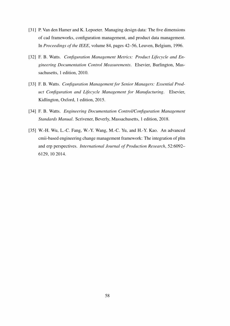
[31] P. Van den Hamer and K. Lepoeter. Managing design data: The five dimensions
of cad frameworks, configuration management, and product data management.
In Proceedings of the IEEE, volume 84, pages 42–56, Leuven, Belgium, 1996.
[32] F. B. Watts. Configuration Management Metrics: Product Lifecycle and En-
gineering Documentation Control Measurements. Elsevier, Burlington, Mas-
sachusetts, 1 edition, 2010.
[33] F. B. Watts. Configuration Management for Senior Managers: Essential Prod-
uct Configuration and Lifecycle Management for Manufacturing. Elsevier,
Kidlington, Oxford, 1 edition, 2015.
[34] F. B. Watts. Engineering Documentation Control/Configuration Management
Standards Manual. Scrivener, Beverly, Massachusetts, 1 edition, 2018.
[35] W.-H. Wu, L.-C. Fang, W.-Y. Wang, M.-C. Yu, and H.-Y. Kao. An advanced
cmii-based engineering change management framework: The integration of plm
and erp perspectives. International Journal of Production Research, 52:6092–
6129, 10 2014.
58
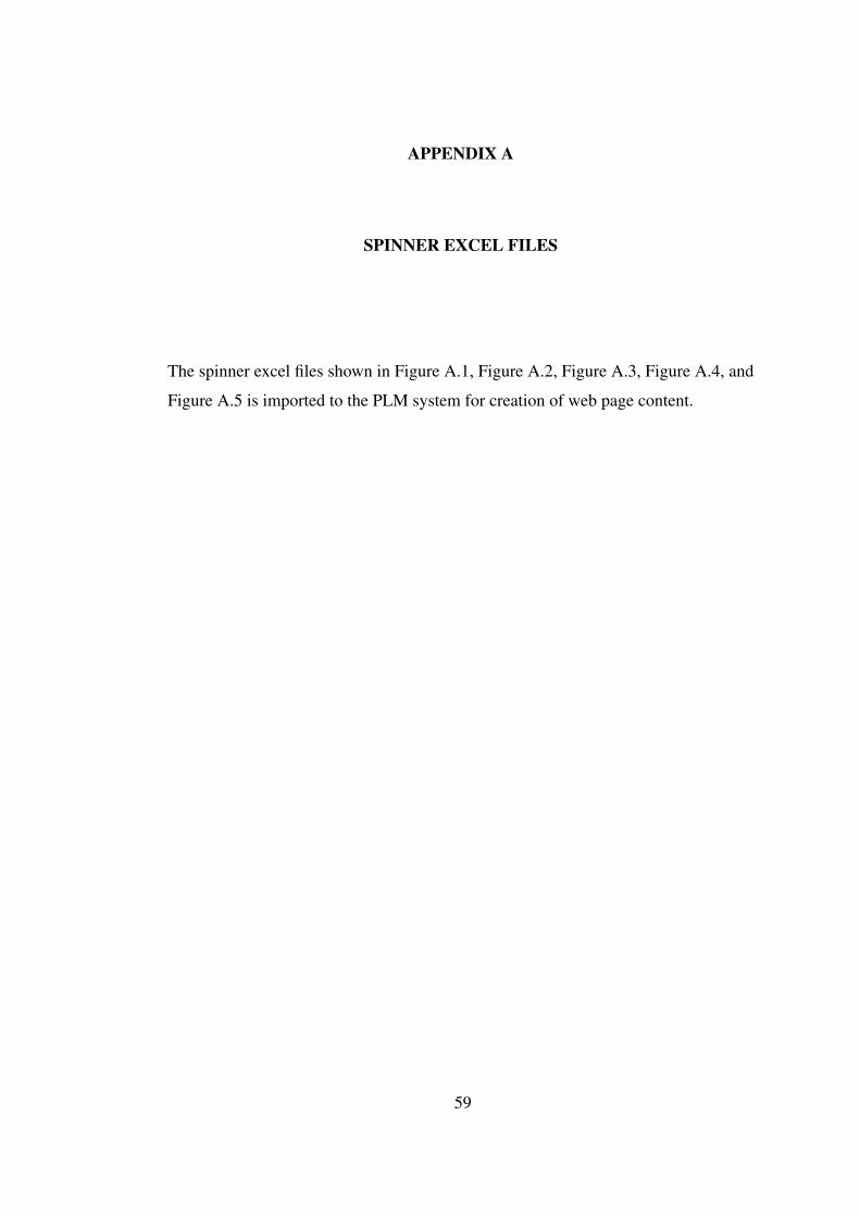
APPENDIX A
SPINNER EXCEL FILES
The spinner excel files shown in Figure A.1, Figure A.2, Figure A.3, Figure A.4, and
Figure A.5 is imported to the PLM system for creation of web page content.
59
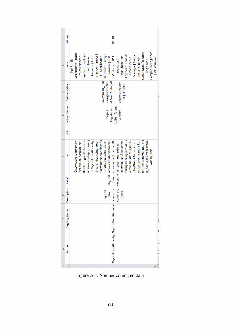
Figure A.1: Spinner command data
60
Figure A.2: Spinner menu data
Figure A.3: Spinner table data
61
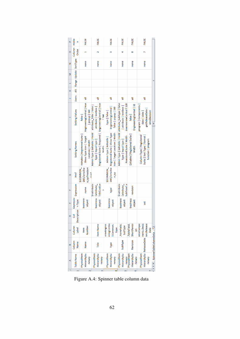
Figure A.4: Spinner table column data
62
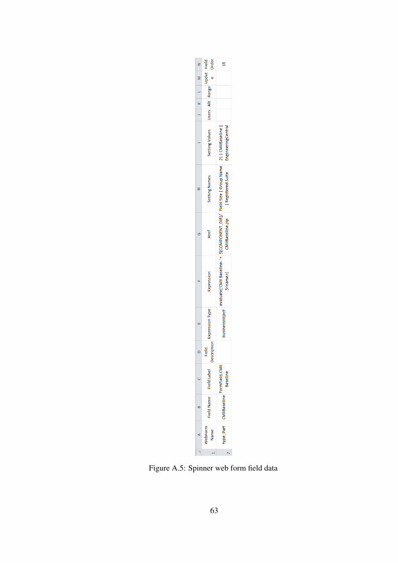
Figure A.5: Spinner web form field data
63

64

APPENDIX B
CMII BASELINE OF TELEMETRY SYSTEM
65
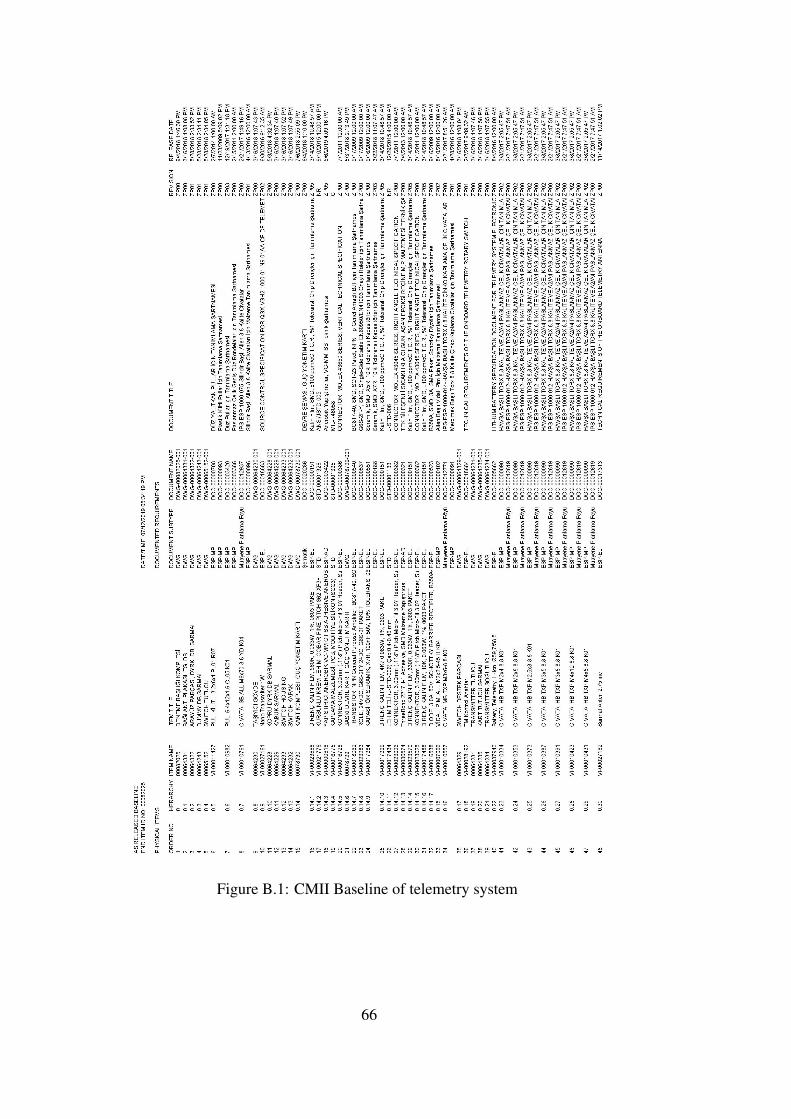
Figure B.1: CMII Baseline of telemetry system
66