Embed Size (px)
Citation preview
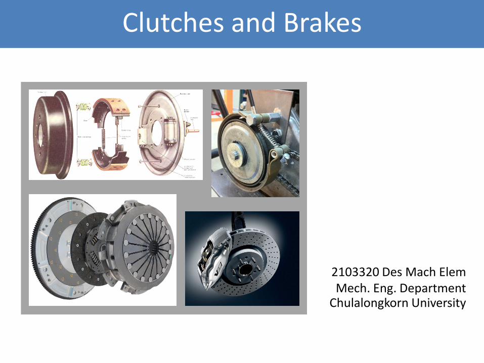
Clutches and Brakes
2103320 Des Mach Elem Mech. Eng. Department
Chulalongkorn University
1 2
Introduction (1)
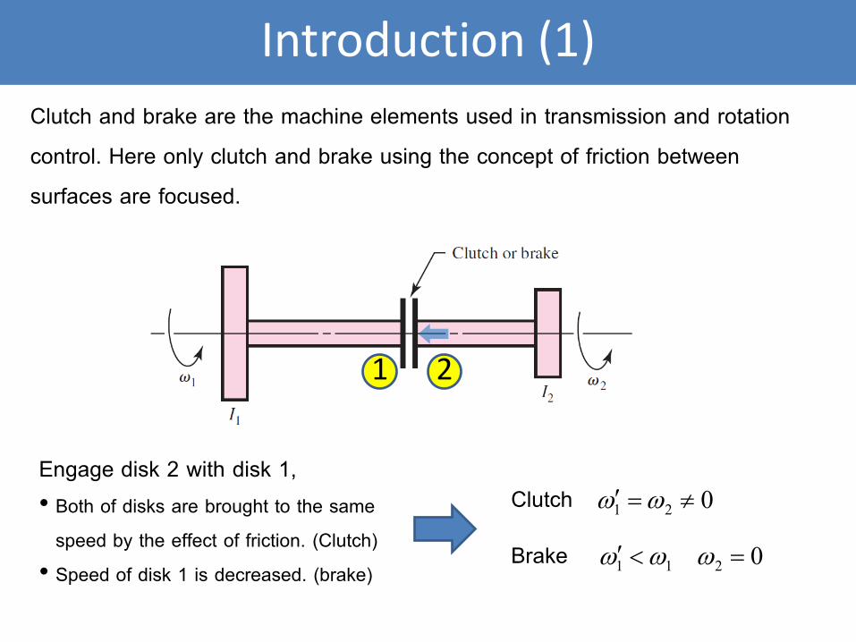
Clutch and brake are the machine elements used in transmission and rotation
control. Here only clutch and brake using the concept of friction between
surfaces are focused.
Engage disk 2 with disk 1, • Both of disks are brought to the same
speed by the effect of friction. (Clutch)
• Speed of disk 1 is decreased. (brake)
021 ≠=′ ωω
0211 =<′ ωωω
Clutch
Brake
Introduction (2)
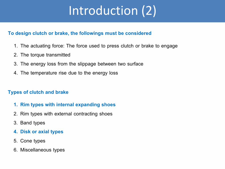
To design clutch or brake, the followings must be considered
1. The actuating force: The force used to press clutch or brake to engage
2. The torque transmitted
3. The energy loss from the slippage between two surface
4. The temperature rise due to the energy loss
Types of clutch and brake
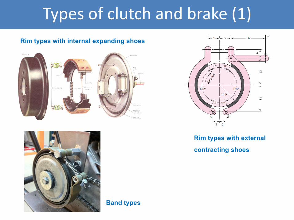
1. Rim types with internal expanding shoes
2. Rim types with external contracting shoes
3. Band types
4. Disk or axial types
5. Cone types
6. Miscellaneous types
Types of clutch and brake (1)
Rim types with internal expanding shoes
Rim types with external
contracting shoes
Band types
Types of clutch and brake (2)
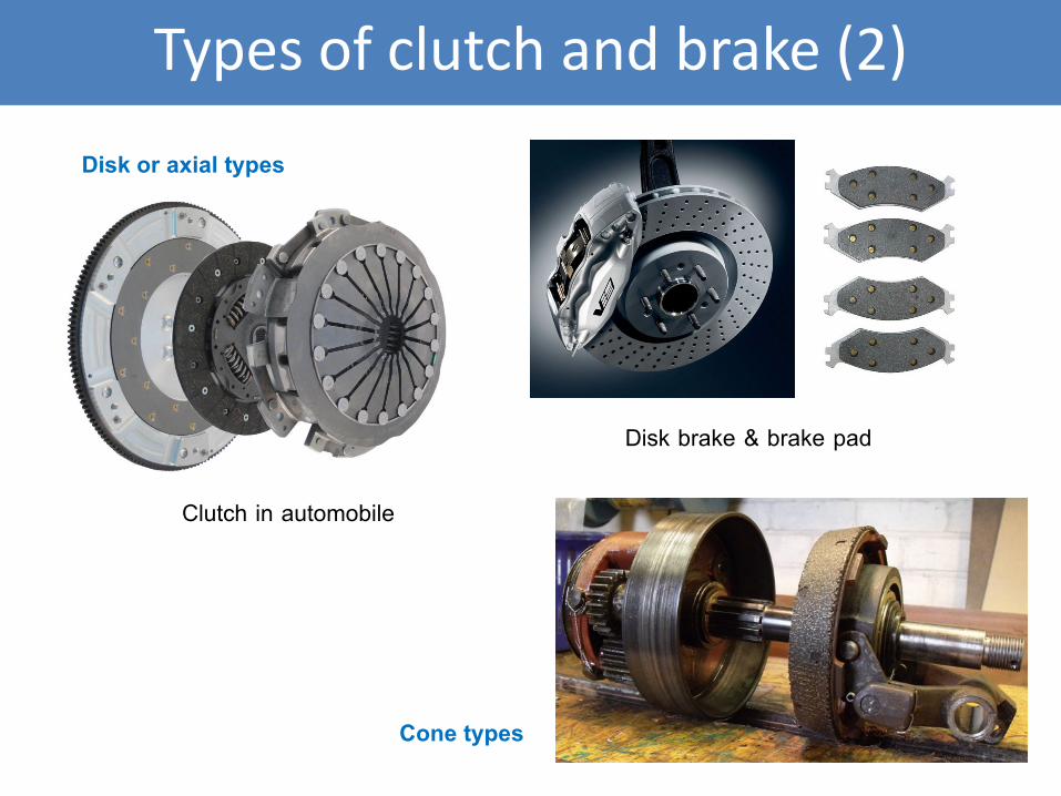
Disk or axial types
Clutch in automobile
Disk brake & brake pad
Cone types
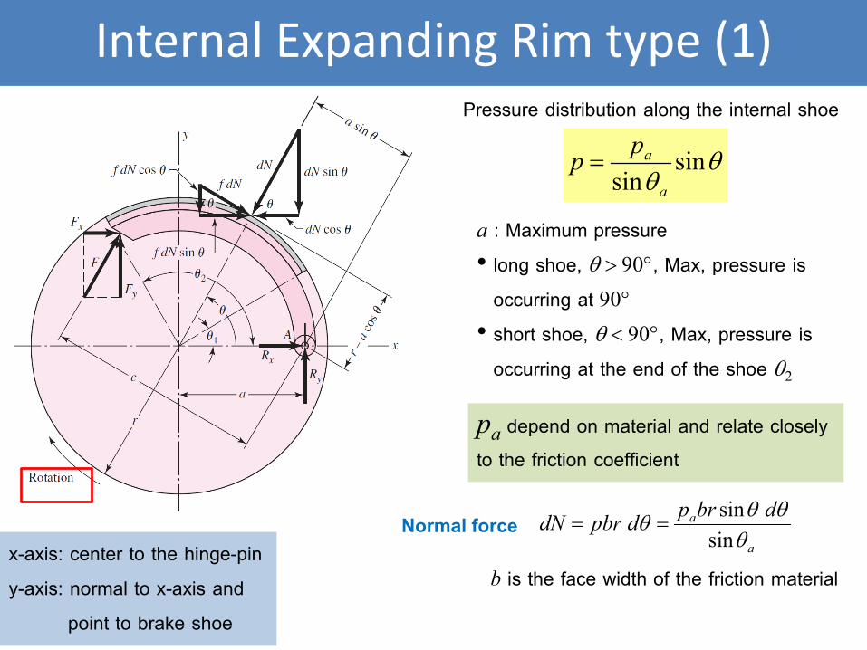
pa depend on material and relate closely to the friction coefficient
θθ
sinsin a
app =
Internal Expanding Rim type (1)
Pressure distribution along the internal shoe
a : Maximum pressure
• long shoe, θ > 90°, Max, pressure is
occurring at 90°
• short shoe, θ < 90°, Max, pressure is
occurring at the end of the shoe θ2
Normal force a
a dbrpdpbrdNθ
θθθsin
sin==
b is the face width of the friction material x-axis: center to the hinge-pin
y-axis: normal to x-axis and
point to brake shoe
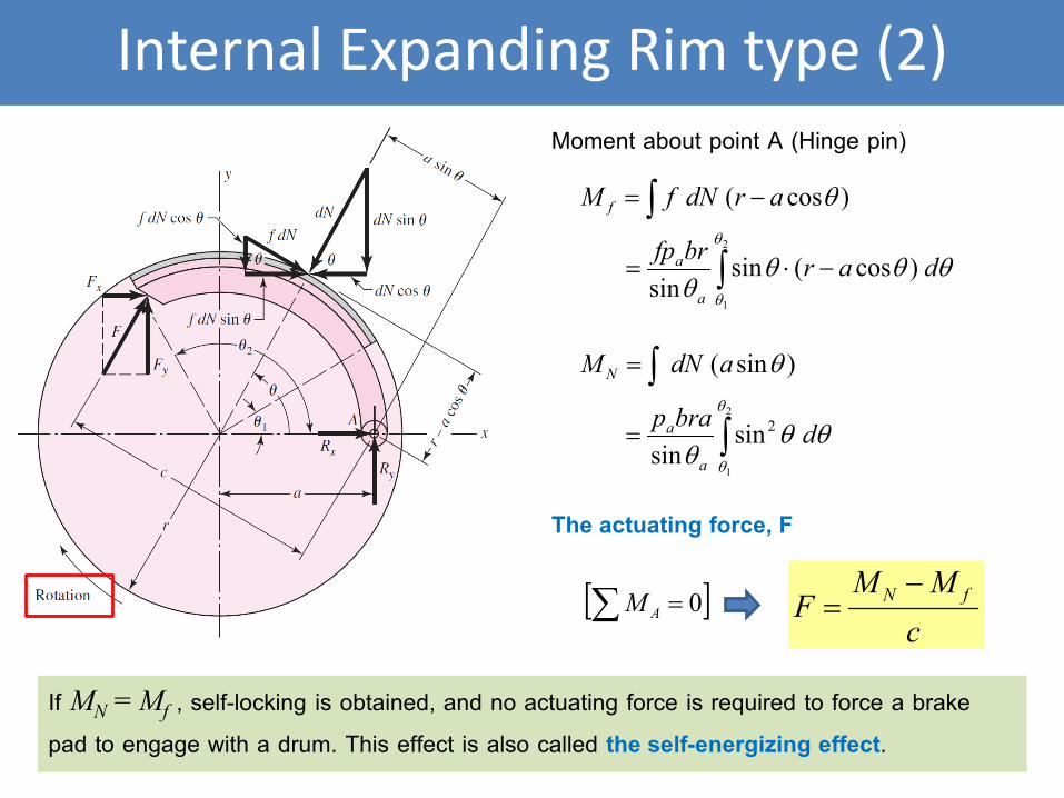
Internal Expanding Rim type (2)
Moment about point A (Hinge pin)
∫
∫−⋅=
−=
2
1
)cos(sinsin
)cos(θ
θ
θθθθ
θ
darbrfp
ardNfM
a
a
f
∫
∫=
=
2
1
2sinsin
)sin(θ
θ
θθθ
θ
dbrap
adNM
a
a
N
The actuating force, F
[ ]0=∑ AMc
MMF fN −
=
If MN = Mf , self-locking is obtained, and no actuating force is required to force a brake
pad to engage with a drum. This effect is also called the self-energizing effect.
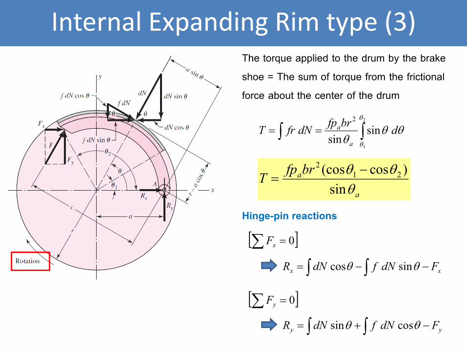
Internal Expanding Rim type (3) The torque applied to the drum by the brake
shoe = The sum of torque from the frictional
force about the center of the drum
∫∫ ==2
1
sinsin
2 θ
θ
θθθ
dbrfpdNfrTa
a
Hinge-pin reactions
xx FdNfdNR −−= ∫∫ θθ sincos
a
abrfpTθ
θθsin
)cos(cos 212 −
=
yy FdNfdNR −+= ∫∫ θθ cossin
[ ]0=∑ xF
[ ]0=∑ yF
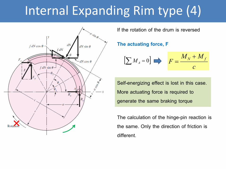
Internal Expanding Rim type (4)
If the rotation of the drum is reversed
The actuating force, F
[ ]0=∑ AMc
MMF fN +
=
× The calculation of the hinge-pin reaction is
the same. Only the direction of friction is
different.
Self-energizing effect is lost in this case.
More actuating force is required to
generate the same braking torque
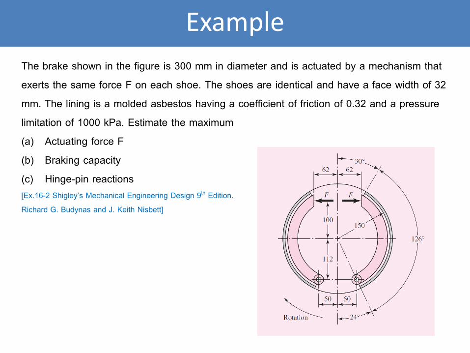
Example
The brake shown in the figure is 300 mm in diameter and is actuated by a mechanism that
exerts the same force F on each shoe. The shoes are identical and have a face width of 32
mm. The lining is a molded asbestos having a coefficient of friction of 0.32 and a pressure
limitation of 1000 kPa. Estimate the maximum
(a) Actuating force F
(b) Braking capacity
(c) Hinge-pin reactions [Ex.16-2 Shigley’s Mechanical Engineering Design 9th Edition.
Richard G. Budynas and J. Keith Nisbett]
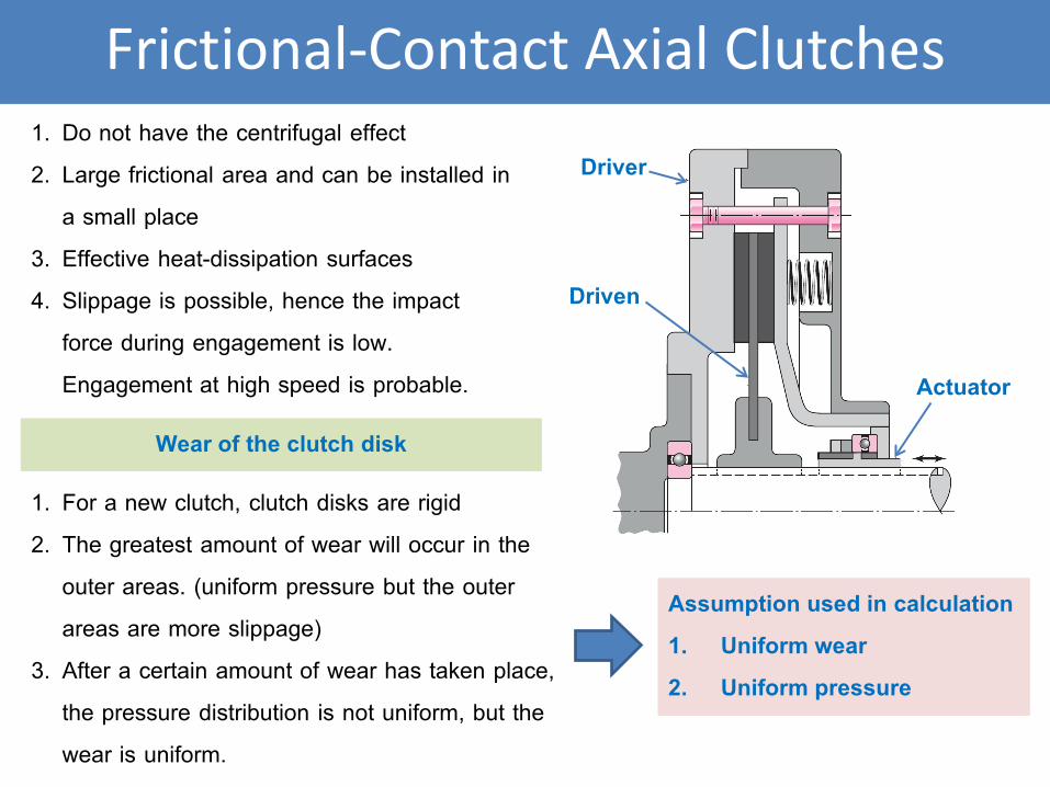
Frictional-Contact Axial Clutches
Driver
Driven
Actuator
1. Do not have the centrifugal effect
2. Large frictional area and can be installed in
a small place
3. Effective heat-dissipation surfaces
4. Slippage is possible, hence the impact
force during engagement is low.
Engagement at high speed is probable.
Wear of the clutch disk
1. For a new clutch, clutch disks are rigid
2. The greatest amount of wear will occur in the
outer areas. (uniform pressure but the outer
areas are more slippage)
3. After a certain amount of wear has taken place,
the pressure distribution is not uniform, but the
wear is uniform.
Assumption used in calculation
1. Uniform wear
2. Uniform pressure
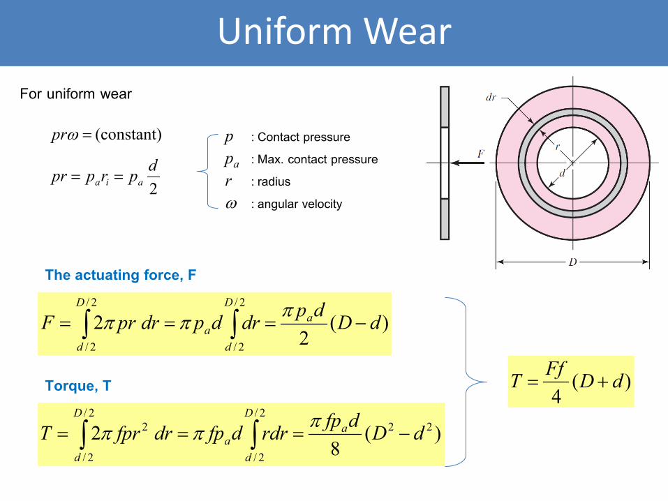
Uniform Wear
For uniform wear
(constant) =ωpr p : Contact pressure
pa : Max. contact pressure
r : radius
ω : angular velocity 2dprppr aia ==
The actuating force, F
)(2
22/
2/
2/
2/
dDdpdrdpdrprF aD
da
D
d
−=== ∫∫πππ
Torque, T
)(8
2 222/
2/
2/
2/
2 dDdfprdrdfpdrfprT aD
da
D
d
−=== ∫∫πππ
)(4
dDFfT +=
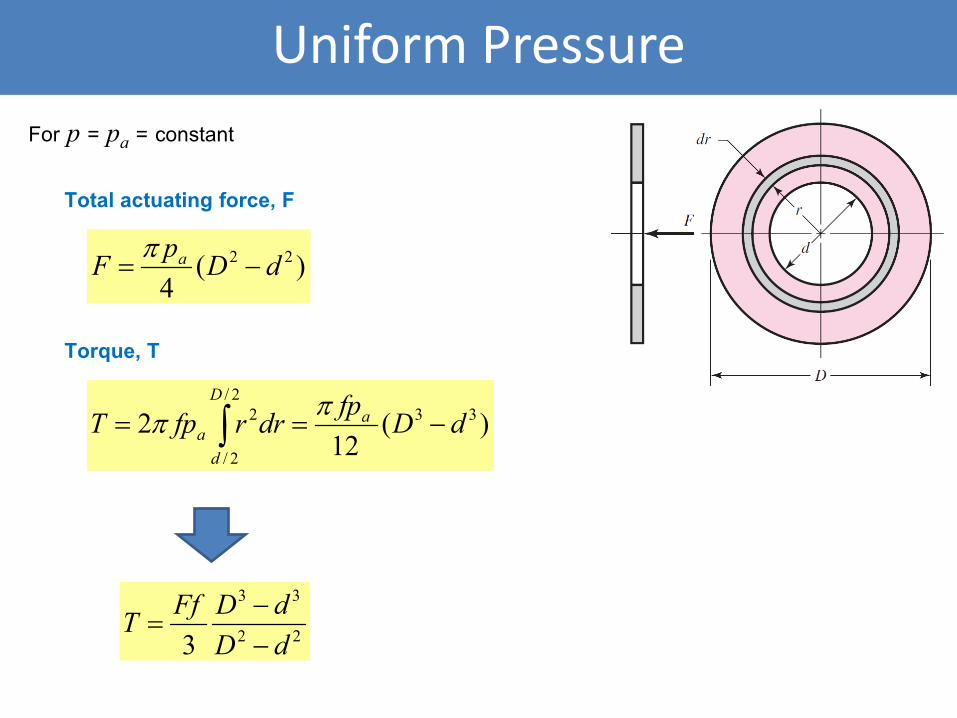
Uniform Pressure
Total actuating force, F
)(4
22 dDpF a −=π
Torque, T
)(12
2 332/
2/
2 dDfpdrrfpT aD
da −== ∫
ππ
22
33
3 dDdDFfT
−−
=
For p = pa = constant
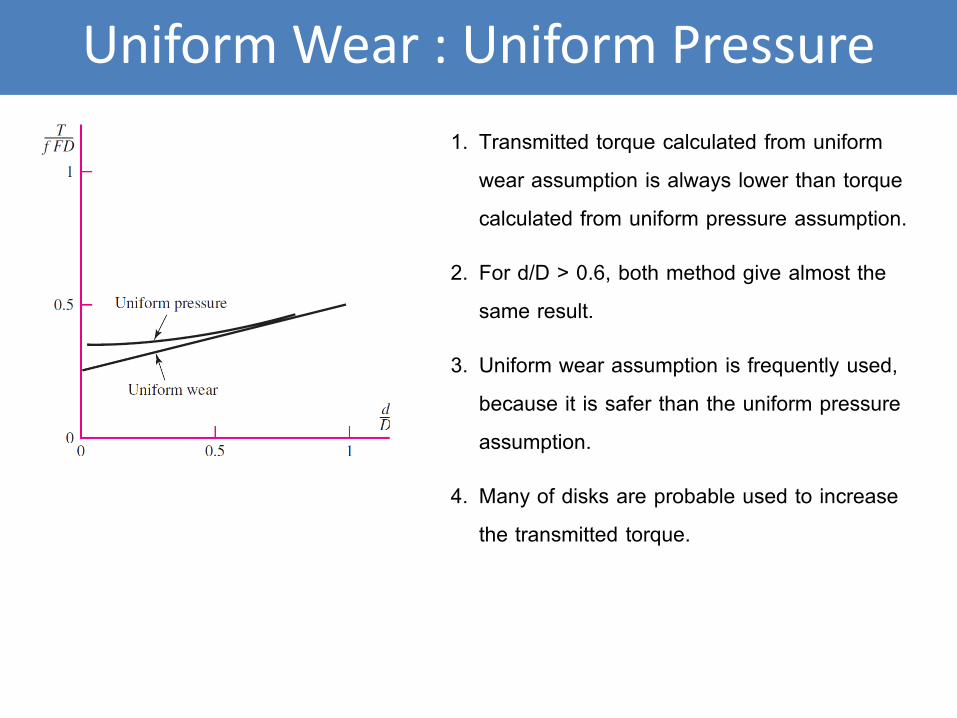
Uniform Wear : Uniform Pressure
1. Transmitted torque calculated from uniform
wear assumption is always lower than torque
calculated from uniform pressure assumption.
2. For d/D > 0.6, both method give almost the
same result.
3. Uniform wear assumption is frequently used,
because it is safer than the uniform pressure
assumption.
4. Many of disks are probable used to increase
the transmitted torque.
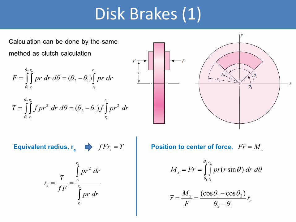
Disk Brakes (1)
Calculation can be done by the same
method as clutch calculation
∫∫ ∫ −==o
i
o
i
r
r
r
r
drprddrprF )( 12
2
1
θθθθ
θ
∫∫ ∫ −==o
i
o
i
r
r
r
r
drprfddrprfT 212
2 )(2
1
θθθθ
θ
Equivalent radius, re TFrf e =
∫
∫==
o
i
o
i
r
r
r
re
drpr
drpr
FfTr
2
Position to center of force, xMrF =
∫ ∫==2
1
)sin(θ
θ
θθ ddrrprrFMo
i
r
rx
ex r
FMr
12
21 )cos(cosθθ
θθ−−
==
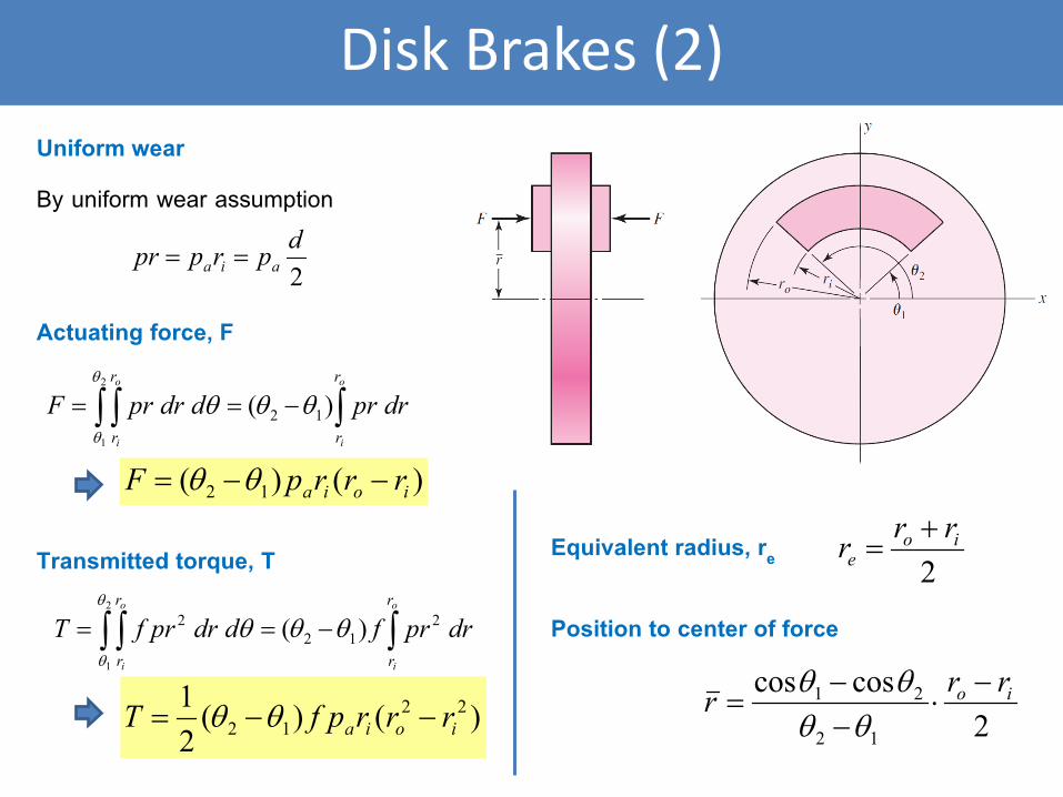
Disk Brakes (2)
∫∫ ∫ −==o
i
o
i
r
r
r
r
drprddrprF )( 12
2
1
θθθθ
θ
∫∫ ∫ −==o
i
o
i
r
r
r
r
drprfddrprfT 212
2 )(2
1
θθθθ
θ
Uniform wear
2dprppr aia ==
By uniform wear assumption
)()( 12 ioia rrrpF −−= θθ
Actuating force, F
)()(21 22
12 ioia rrrpfT −−= θθ
Transmitted torque, T Equivalent radius, re 2io
errr +
=
Position to center of force
2coscos
12
21 io rrr −⋅
−−
=θθ
θθ
Braking disk
Shoe and lining
Brake fluid
Piston
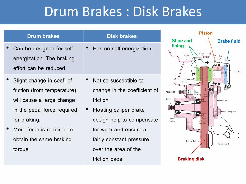
Drum Brakes : Disk Brakes
Drum brakes Disk brakes
• Can be designed for self-
energization. The braking
effort can be reduced.
• Has no self-energization.
• Slight change in coef. of
friction (from temperature)
will cause a large change
in the pedal force required
for braking.
• More force is required to
obtain the same braking
torque
• Not so susceptible to
change in the coefficient of
friction
• Floating caliper brake
design help to compensate
for wear and ensure a
fairly constant pressure
over the area of the
friction pads
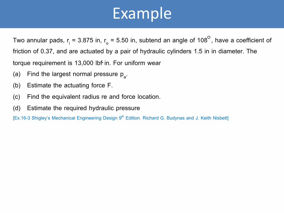
Example
Two annular pads, ri = 3.875 in, ro = 5.50 in, subtend an angle of 108°, have a coefficient of friction of 0.37, and are actuated by a pair of hydraulic cylinders 1.5 in in diameter. The
torque requirement is 13,000 lbf⋅in. For uniform wear (a) Find the largest normal pressure pa.
(b) Estimate the actuating force F.
(c) Find the equivalent radius re and force location.
(d) Estimate the required hydraulic pressure [Ex.16-3 Shigley’s Mechanical Engineering Design 9th Edition. Richard G. Budynas and J. Keith Nisbett]
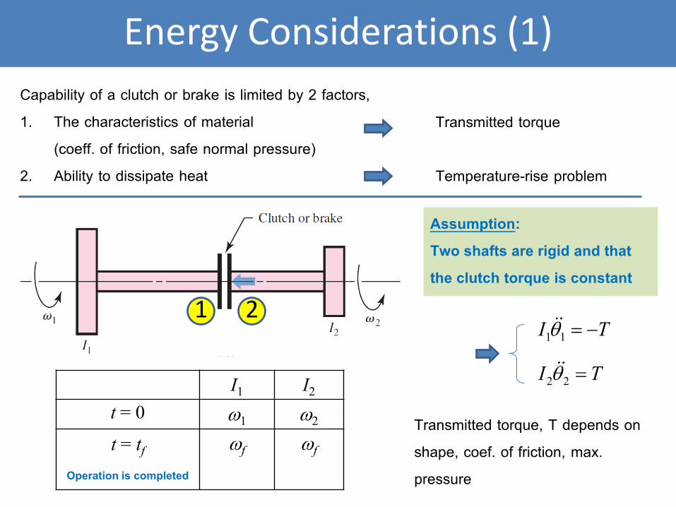
Energy Considerations (1)
1 2
Capability of a clutch or brake is limited by 2 factors,
1. The characteristics of material
(coeff. of friction, safe normal pressure)
2. Ability to dissipate heat
Assumption:
Two shafts are rigid and that
the clutch torque is constant
TI −=11θ
TI =22θ
Transmitted torque, T depends on
shape, coef. of friction, max.
pressure
I1 I2
t = 0 ω1 ω2
t = tf
Operation is completed
ωf ωf
Transmitted torque
Temperature-rise problem
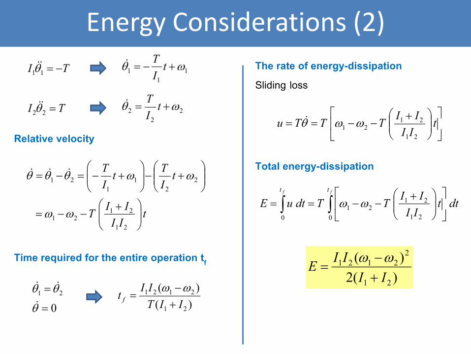
Energy Considerations (2)
Relative velocity
tIIIIT
tITt
IT
+−−=
+−
+−=−=
21
2121
22
11
21
ωω
ωωθθθ
Time required for the entire operation tf
021
=
=
θ
θθ
)()(
21
2121
IITIIt f +
−=
ωω
TI −=11θ
TI =22θ
11
1 ωθ +−= tIT
22
2 ωθ += tIT
The rate of energy-dissipation
Sliding loss
+−−== t
IIIITTTu21
2121 ωωθ
Total energy-dissipation
∫∫
+−−==
ff tt
dttIIIITTdtuE
0 21
2121
0
ωω
)(2)(
21
22121
IIIIE
+−
=ωω
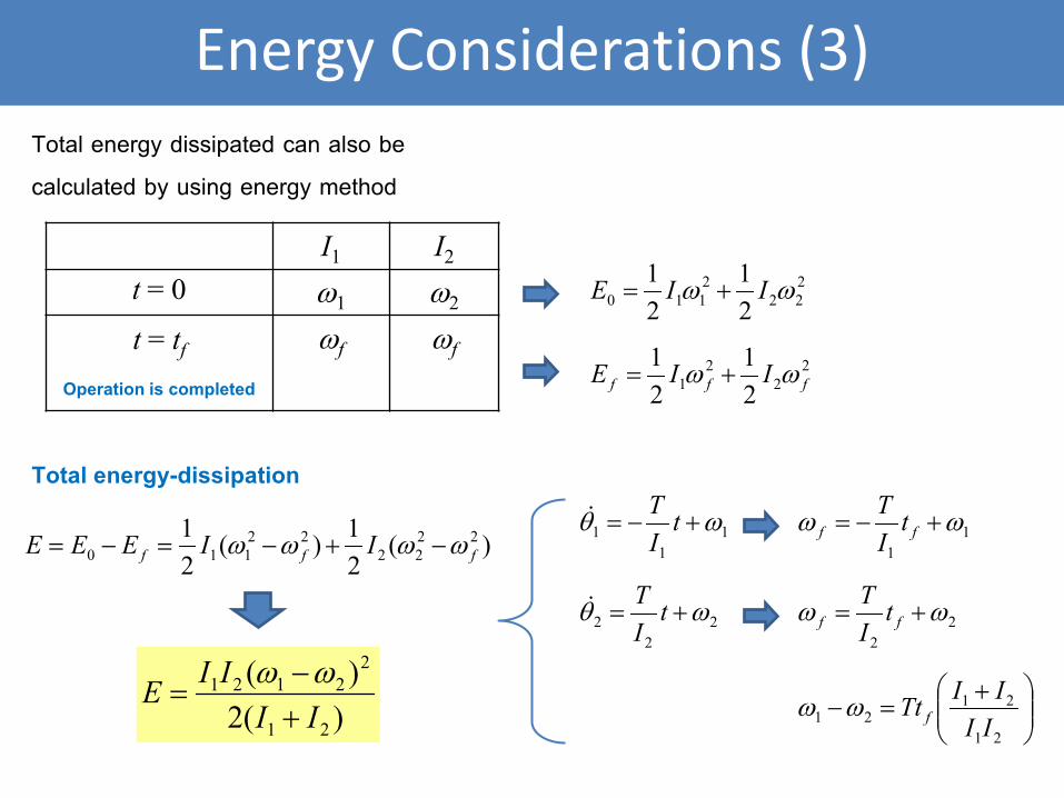
Energy Considerations (3)
Total energy dissipated can also be
calculated by using energy method
I1 I2
t = 0 ω1 ω2
t = tf
Operation is completed
ωf ωf
222
2110 2
121 ωω IIE +=
22
21 2
121
fff IIE ωω +=
)(21)(
21 22
2222
110 fff IIEEE ωωωω −+−=−=1
11 ωθ +−= t
IT
22
2 ωθ += tIT
11
ωω +−= ff tIT
22
ωω += ff tIT
+=−
21
2121 II
IITt fωω)(2)(
21
22121
IIIIE
+−
=ωω
Total energy-dissipation
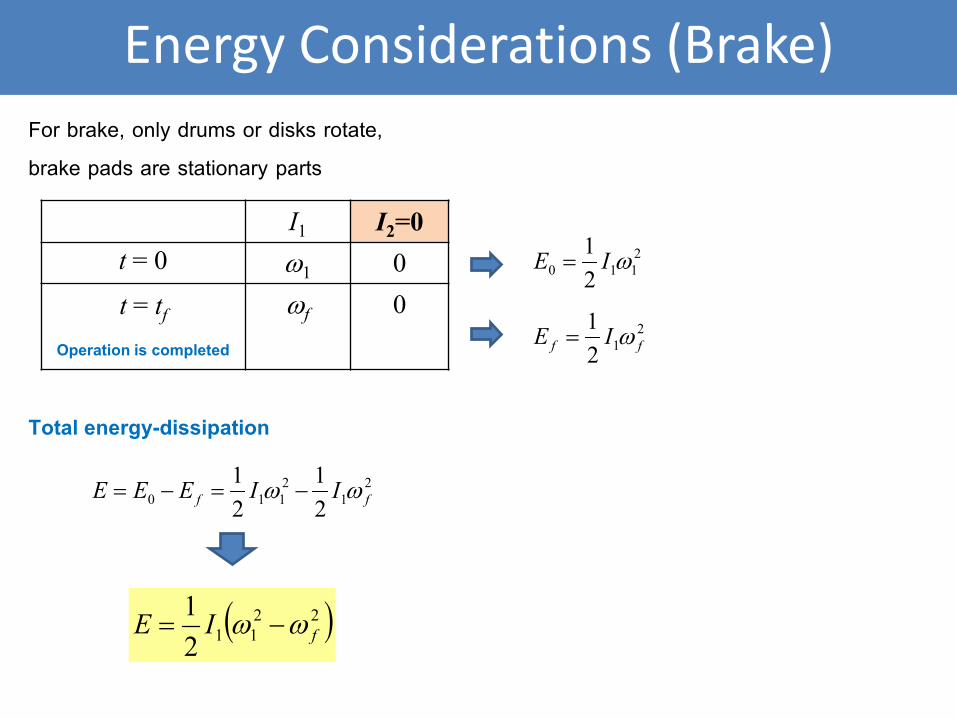
Energy Considerations (Brake)
For brake, only drums or disks rotate,
brake pads are stationary parts
I1 I2=0
t = 0 ω1 0
t = tf
Operation is completed
ωf 0
2110 2
1 ωIE =
21
2110 2
121
ff IIEEE ωω −=−=
( )22112
1fIE ωω −=
Total energy-dissipation
212
1ff IE ω=
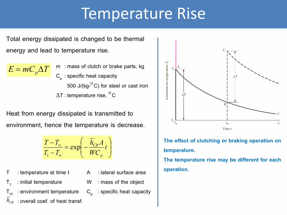
Temperature Rise
Total energy dissipated is changed to be thermal
energy and lead to temperature rise.
TmCE p∆= m : mass of clutch or brake parts, kg
Cp : specific heat capacity
500 J/(kg-°C) for steel or cast iron
∆T : temperature rise, °C
Heat from energy dissipated is transmitted to
environment, hence the temperature is decrease.
−=
−−
∞
∞ tWC
AhTTTT
p
CRexp1
T : temperature at time t
T1 : initial temperature
T∞ : environment temperature
: overall coef. of heat transf. CRh
A : lateral surface area
W : mass of the object
Cp : specific heat capacity
The effect of clutching or braking operation on
temperature.
The temperature rise may be different for each
operation.
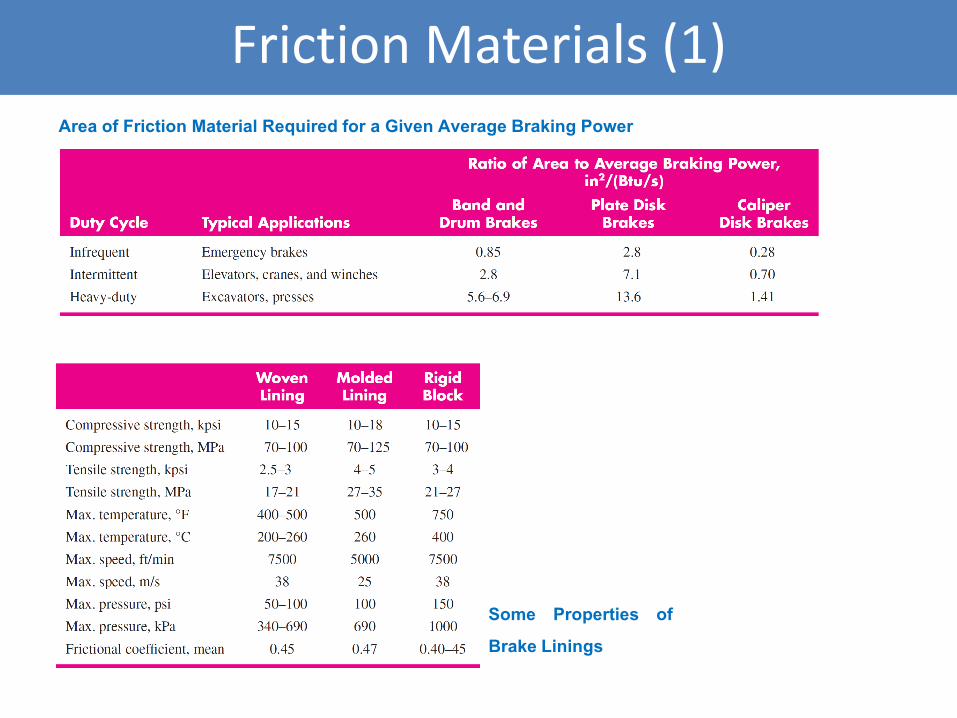
Friction Materials (1)
Area of Friction Material Required for a Given Average Braking Power
Some Properties of
Brake Linings
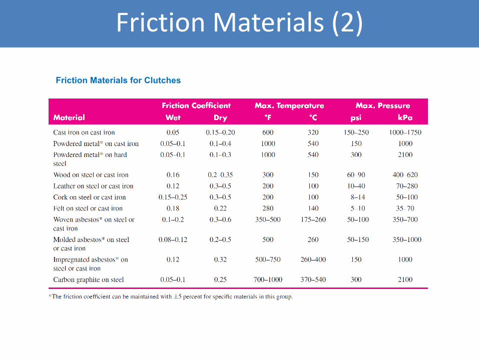
Friction Materials (2)
Friction Materials for Clutches
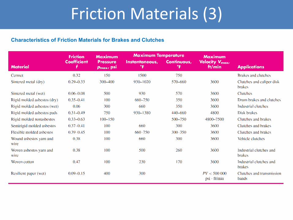
Friction Materials (3)
Characteristics of Friction Materials for Brakes and Clutches


![Index 621 [pioneer.netserv.chula.ac.th]pioneer.netserv.chula.ac.th/~nsuvit/574/621.734.IndexSolutionManu… · Copyright Cambridge University Press 2003. On-screen viewing permitted](https://img.pdfslide.us/doc/110x75/5eace47e4bd3b43d3b46033a/index-621-nsuvit574621734indexsolutionmanu-copyright-cambridge-university.jpg)