Embed Size (px)
Citation preview
Research ArticleCloud-Based Experimental Platform for the Space-GroundIntegrated Network
Xiaofeng Wang , Xinyu Chen , Haiyang Ye , Yuan Liu , and Guizhu Zhang
School of Artificial Intelligence and Computer Science, Jiangnan University, Wuxi 214122, China
Correspondence should be addressed to Xiaofeng Wang; [email protected]
Received 13 August 2020; Revised 27 September 2020; Accepted 5 October 2020; Published 21 October 2020
Academic Editor: Weizhe Zhang
Copyright © 2020 XiaofengWang et al. This is an open access article distributed under the Creative Commons Attribution License,which permits unrestricted use, distribution, and reproduction in any medium, provided the original work is properly cited.
The space-ground integrated network (SGIN) is an important direction of future network development and is expected to play animportant role in edge computing for the Internet of Things (IoT). Through integration with an SGIN, IoT applications can provideservices with long-distance and wide-coverage features. However, SGINs are typical large-scale and time-varying networks forwhich new network technologies, protocols, and applications must be rigorously evaluated and validated. Therefore, a reliableexperimental platform is necessary for SGINs. This paper presents a cloud-based experimental platform for the SGIN contextnamed SGIN-Stack. First, the architecture of SGIN-Stack, which combines the Systems Tool Kit (STK) and OpenStack, isdescribed. Based on this architecture, a seamless linkage between OpenStack and STK is achieved to realize synchronous,dynamic, and real-time network emulation for an SGIN, and the dynamic differential compensation technology and a randomnumber generation algorithm are applied to improve the emulation accuracy for satellite links. Finally, an emulation scenario isconstructed that includes six space-based backbone nodes, sixty-six space-based access nodes, and a ground station. Based onthis emulation scenario, experiments concerning the satellite link delays, bit error ratio (BER), and throughput are carried out toprove the high fidelity of our SGIN-Stack platform. Emulation experiments involving satellite orbital maneuvers and attitudeadjustments show that SGIN-Stack can be used for dynamic and real-time SGIN emulation.
1. Introduction
Space-ground integrated networks (SGINs) [1, 2], space-terrestrial integrated networks (STINs) [3], and space-air-ground integrated networks (SAGINs) [4] are highly hetero-geneous complex networks that include a space-based back-bone network, a space-based access network, and a ground-based backbone network. The goal in proposing an SGIN isto construct an integrated, expandable, cross-supported,and reconfigurable space-ground information system forapplications.
SGINs have a wide range of applications in many fields,especially in the field of edge computing for the Internet ofThings (IoT). For instance, Wang et al. [5] proposed to trans-form the traditional satellite into a space edge computingnode, which takes less time and consumes less energy; Chenet al. [6] proposed a SAGIN edge/cloud computing architec-ture for offloading the computation-intensive applications.With SGINs, edge computing for IoT has transcended phys-
ical limitations and realized the “Internet of Everything” inthe real sense [7, 8]. For example, in [9], the authors intro-duced related research results on SGINs for the constructionof maritime networks to enable the development of IoT ser-vices in the sea environment. A new space-air-ground(SAG) IoT network paradigm was proposed in [10], wherethe authors introduced related key technologies to meet theneeds of a variety of IoT fields, such as aviation and smart cityconstruction.
Since SGINs are large-scale complex networks with het-erogeneity and time-variability features, the integration ofSGIN technology into the IoT also presents new technicalrequirements, such as requirements on resource management,traffic distribution, and protocol optimization [10, 11]; there-fore, many new technologies and protocols continue toemerge. For instance, Zhao et al. [12] proposed an identity-based authentication scheme called MASIT for SAG IOT(SIoT). Liu et al. [13] proposed a multibeam satellite industrialIoT (IIOT) based on nonorthogonal multiple access (NOMA)
HindawiWireless Communications and Mobile ComputingVolume 2020, Article ID 8893187, 20 pageshttps://doi.org/10.1155/2020/8893187
to achieve wide-area coverage and improved service perfor-mance. However, any such new technologies, protocols, andIoT application services must be rigorously evaluated and val-idated before an SGIN is actually deployed [11]; therefore, areliable experimental platform for SGIN is necessary [14].
As cloud platforms and virtualization technologies haveevolved to be capable of supporting scalable and high-fidelity virtual networks, network emulation based on cloudplatforms and virtualization has become an emergingresearch trend [15, 16]. For example, based on a commoditycloud platform, a network protocol emulation platformcalled CloudNet was implemented in [17]; by means of alightweight virtualization technique called LXC containers,CloudNet is scalable to thousand-node emulated networks.At present, the OpenStack cloud platform [18], which incor-porates state-of-the-art technologies, such as software-defined networking (SDN) [19], full virtualization (kernelvirtual machine, KVM), and lightweight virtualization(Docker), has become the foremost mainstream cloud plat-form in the industry, with features such as high efficiencyand stability; consequently, it is considered a good choicefor developing emulation platforms [15, 20].
An SGIN is a typical large-scale and time-varying net-work with variable delay and bit error ratio (BER), unstableend-to-end paths between satellites, and satellite maneuver-ing capabilities [4, 15, 21]. Consequently, traditional cloudplatforms cannot meet the emulation requirements for anSGIN [15]. Although an OpenStack-based network emula-tion platform named EmuStack was proposed in [15] forthe real-time network emulation of delay-tolerant networks(DTN), including the time-varying emulation of satellite net-work characteristics (e.g., bandwidth, delay, and BER), Emu-Stack ignores the maneuverability of satellites, whichnecessitates the real-time emulation of dynamical changesin the emulated SGIN (e.g., dynamic satellite managementstrategies [21]). To address this problem, an emulation plat-form for SGINs named SGIN-Stack is proposed in this paper.
SGIN-Stack is based on OpenStack, and through theincorporation of technologies, such as SDN, KVM, andDocker, SGIN-Stack achieves high fidelity in emulating thenodes of an SGIN and high throughput and flexibility inemulating the SGIN’s links. To ensure emulation fidelity forlinks, the emulation source data of SGIN-Stack, whichinclude the orbit data of the satellites, an atmospheric rainattenuation model, and communication calculation for thesatellite links, are computed using the Systems Tool Kit(STK) [22], which is a leading analysis software packagedeveloped by Analytical Graphics, Inc. (AGI) of the USA thatcan be used to dynamically design and simulate multilayersatellite networks [23]. SGIN-Stack implements a seamlessand high-efficiency linkage between OpenStack and STK toblend the advantages of both. Through this linkage betweenOpenStack and STK, SGIN-Stack can realize dynamic, accu-rate, and real-time SGIN emulation. The emulation networkgenerated by SGIN-Stack on OpenStack is called the SGINemulation network. The SGIN emulation network can bedynamically driven by the accurate data computed by STK.Besides, for any dynamic changes in the SGIN emulation net-work, such as satellite orbital maneuvers and attitude adjust-
ments, STK can be further leveraged to recompute thecorresponding data in real-time. Furthermore, SGIN-Stackintegrates not only the Linux Traffic Control (TC) tools[24] and SDN techniques (similar to EmuStack [15]) but alsothe dynamic differential compensation technique and a ran-dom number generation algorithm by means of OpenStack.With these techniques, SGIN-Stack can more accuratelyemulate variable delay and BER characteristics as well asunstable end-to-end paths between satellites.
Overall, the main advantages of SGIN-Stack are asfollows:
(1) Through the seamless and high-efficiency linkagebetween OpenStack and STK, SGIN-Stack can realizenot only the realistic emulation of SGINs but also thereal-time emulation of dynamic changes in SGINs,such as unstable paths between satellites and satellitemaneuvering
(2) By virtue of the proposed dynamic differential com-pensation technique and random number generationalgorithm, SGIN-Stack can emulate satellite linkswith improved accuracy
(3) SGIN-Stack integrates two existing virtualizationmethods, that is, KVM and Docker, to leverage theunique benefits of each. Space-based backbone satel-lite nodes and gateway station nodes are emulated byKVM, which can meet the high throughput require-ments of space-based backbone satellite links.Space-based access satellite nodes are emulated byDocker, which can achieve fast deployment and effi-cient utilization of physical resources
This paper is organized as follows. First, in Section 2, pre-vious works related to SGIN emulation are introduced. Sec-ond, the architecture of SGIN-Stack is described in Section3. Several core implementations for the accurate, dynamic,and real-time emulation of SGINs are described in detail inSection 4. In Section 5, an SGIN scenario is constructed withSGIN-Stack, and the corresponding experimental results arediscussed. Finally, we conclude this paper and describe direc-tions of future research in Section 6.
2. Related Work
STK [22] is a commercially available software package forvarious satellite performance analyses, including the valida-tion of new theoretical models [25], the detailed animationof spacecraft simulations [26], the calculation of satellite cov-erage information [27, 28], the design of network topologies[29], and the evaluation of satellite maneuvers [30]. STKhas strong modeling and analysis capabilities for satellite net-works but lacks a network performance analysis mechanism[31]; hence, it cannot effectively emulate a satellite network inregard to network protocols, dynamic throughput, andsecure communication methods [28].
A method of designing satellite constellation topologiesin STK and exporting them to the ns-2 discrete event simula-tor was proposed in [29] for evaluating the network
2 Wireless Communications and Mobile Computing
performance of satellite networks. In [32], STK wascombined with the QualNet network simulator to modelcommunication with Internet protocols. The methods usedin [29, 32] combine the advantages of both STK and networksimulators and thus are more promising for evaluatingSGINs. However, because network simulators have difficul-ties emulating complicated environments [16], providing rel-evant and comprehensive details [15], and generatingrealistic data flows [14], the predominant trend of evaluationtechnology has shifted from simulations to experimental test-beds [16].
On the basis of SDN and virtualization technologies, ascalable, reconfigurable, and flexible network emulation plat-form for space information networks was proposed in [14].This platform can emulate the physical characteristics of sat-ellite nodes (such as the CPU frequency, memory, and oper-ating system) and the characteristics of the links betweennodes (such as the traffic rate, BER, and delay), where thesource data for the link characteristics are derived fromSTK. Our work differs from this platform in that we attemptto emulate not only these variable characteristics but also themaneuvering of satellites.
An OpenStack-based DTN emulation platform namedEmuStack was proposed in [15], in which lightweight virtua-lization (Docker) is used to support a large-scale topology(up to hundreds of nodes). EmuStack integrates TC andSTK with OpenStack to emulate the characteristics of satellitelinks. In addition to using TC and STK, our work attempts tofurther improve the emulation fidelity for satellite linksthrough methods such as dynamic differential compensationand a random number generation algorithm. Moreover, ourwork implements a more seamless linkage between Open-Stack and STK than that in EmuStack in order to emulatedynamic changes in SGINs.
TUNIE, a testbed for evaluating DTNs, was designed in[16]. In this testbed, virtualization and SDN technologiesare exploited to implement a realistic and reliable DTN envi-ronment, and time-varying bit rates, error rates, and trans-mission delays are implemented by controlling datatransmission. TUNIE requires the further integration ofabundant models for the emulation of an SGIN, which is ahighly heterogeneous and complex network.
3. Architecture of SGIN-Stack
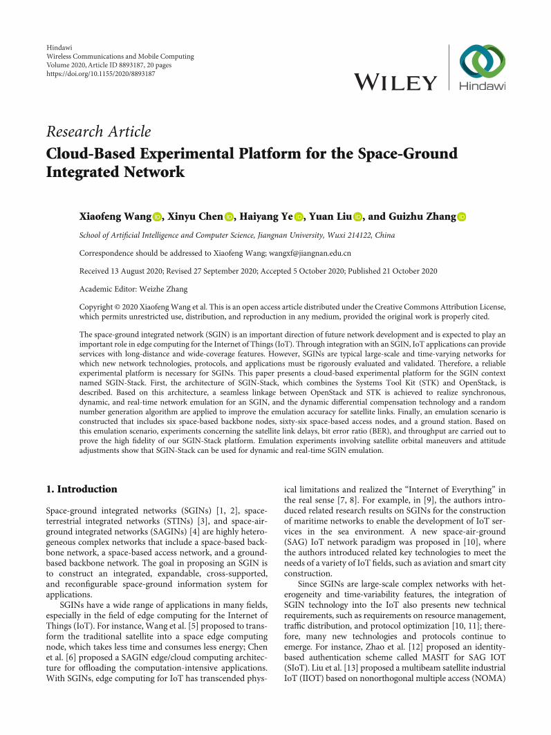
Figure 1 illustrates the overall architecture of SGIN-Stack,which is based on the OpenStack cloud architecture. TheOpenStack cloud architecture mainly includes a controlnode, a network node, and multiple compute nodes. Thecontrol node is responsible for managing OpenStack, the net-work node provides L2 and L3 network services for Open-Stack, and the compute node is responsible for theoperation of virtual machines. The architecture of SGIN-Stack includes an STK simulation node, a network node,and several physical emulation nodes. The network node cor-responds to the OpenStack network node and provides net-work services for SGIN-Stack. The various modules of thephysical emulation nodes are integrated into all OpenStackcompute nodes. The STK simulation node is built on a host.
In the design of the overall platform architecture, severalideas originating from SDN are adopted. The STK simulationnode acts as the application plane to generate simulationinformation source data. According to the simulation infor-mation source data, the physical emulation node acts as thecontrol plane to manage the traffic of the SGIN emulationnetwork. The various virtual network devices in the SGINemulation network in OpenStack form the data plane.
The architecture of SGIN-Stack is based on an emulationconcept relying on multiscale integration combining full andlightweight virtualization technologies. Space-based back-bone nodes and gateway stations have high throughput andare emulated using full virtualization technology. Space-based access nodes with lower throughput requirements areemulated using lightweight virtualization technology. Theintegration of the two virtualization technologies not onlyensures the emulation performance but also realizes the effi-cient utilization of physical resources.
The three main components of the architecture depictedin Figure 1 are described in detail in sections 3.1, 3.2, and 3.3.
3.1. STK Simulation Node. The STK simulation node mainlyconsists of STK11 and MATLAB R2013a. The STKX moduleis designed to provide two-way communication between STKandMATLAB. STK is used to simulate the satellite nodes andground nodes. The network simulated in STK is called theSGIN simulation network. Each MATLAB module obtainsthe relevant data from STK via the STKX module and eitherproceeds with further processing or transmits relevant com-mands to STK to control the SGIN simulation network inSTK in reverse. The functions of each MATLAB moduleare described as follows:
The topology monitor module is responsible for moni-toring the dynamic changes in network topology in STK. Itmonitors the list of objects in STK by means of the “stkObj-Names” command, compares the results against the existinglist of objects to monitor the dynamic behaviors of objectaddition and deletion in STK, and sends the information onany such dynamic changes in STK to the topology linkagecontrol module in each physical emulation node. The topol-ogy linkage control module changes the topology of the SGINemulation network in accordance with the information fromthe topology monitor module. Thus, the topology monitormodule and the topology linkage control module are linkedto realize the real-time and dynamic emulation of the net-work topology.
The main task of the STK report acquisition module is toobtain reports of data on link characteristics. Its main func-tion is to extract a report of link performance data fromSTK via the “stkAccReport” command and process thesedata to generate the link characteristics, such as delay andpacket loss rate. These link characteristics are then sent tothe link characteristics linkage control module via the north-bound interface of the corresponding physical emulationnode in order to set the link characteristics in the SGIN emu-lation network. Thus, the STK report acquisition module andthe link characteristics linkage module are linked to realizethe real-time and dynamic emulation of the linkcharacteristics.
3Wireless Communications and Mobile Computing
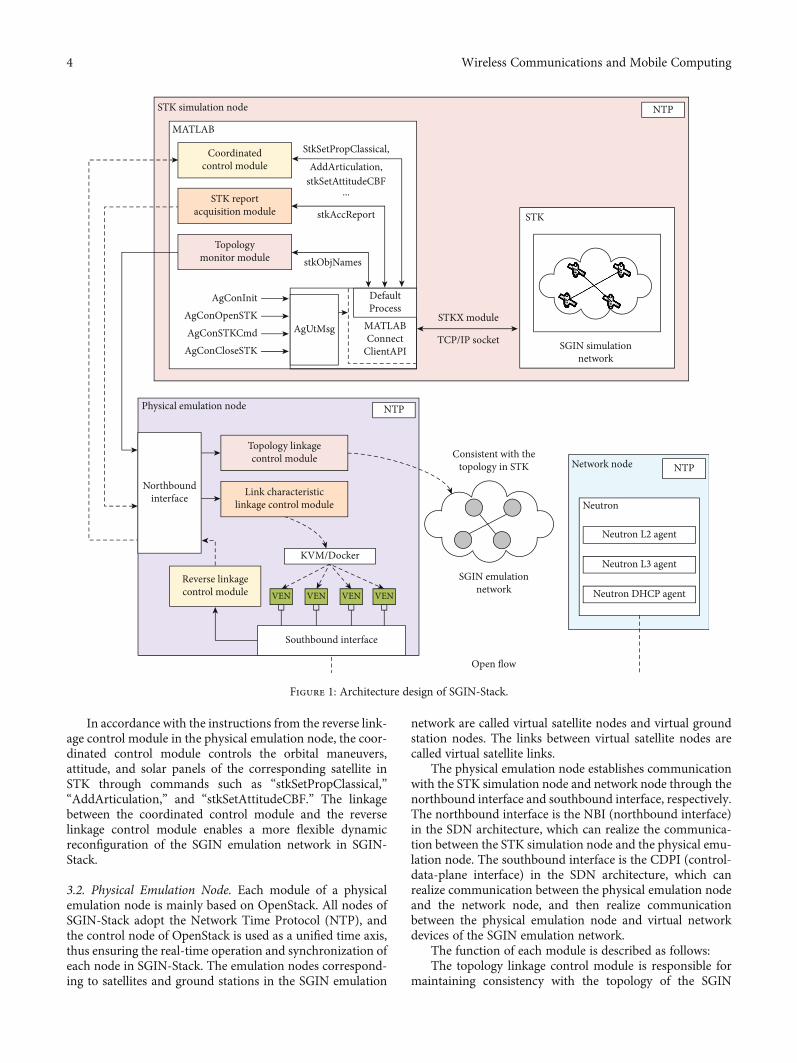
In accordance with the instructions from the reverse link-age control module in the physical emulation node, the coor-dinated control module controls the orbital maneuvers,attitude, and solar panels of the corresponding satellite inSTK through commands such as “stkSetPropClassical,”“AddArticulation,” and “stkSetAttitudeCBF.” The linkagebetween the coordinated control module and the reverselinkage control module enables a more flexible dynamicreconfiguration of the SGIN emulation network in SGIN-Stack.
3.2. Physical Emulation Node. Each module of a physicalemulation node is mainly based on OpenStack. All nodes ofSGIN-Stack adopt the Network Time Protocol (NTP), andthe control node of OpenStack is used as a unified time axis,thus ensuring the real-time operation and synchronization ofeach node in SGIN-Stack. The emulation nodes correspond-ing to satellites and ground stations in the SGIN emulation
network are called virtual satellite nodes and virtual groundstation nodes. The links between virtual satellite nodes arecalled virtual satellite links.
The physical emulation node establishes communicationwith the STK simulation node and network node through thenorthbound interface and southbound interface, respectively.The northbound interface is the NBI (northbound interface)in the SDN architecture, which can realize the communica-tion between the STK simulation node and the physical emu-lation node. The southbound interface is the CDPI (control-data-plane interface) in the SDN architecture, which canrealize communication between the physical emulation nodeand the network node, and then realize communicationbetween the physical emulation node and virtual networkdevices of the SGIN emulation network.
The function of each module is described as follows:The topology linkage control module is responsible for
maintaining consistency with the topology of the SGIN
STK simulation node
MATLAB
Coordinatedcontrol module
STK reportacquisition module
Topologymonitor module
StkSetPropClassical,AddArticulation,
stkSetAttitudeCBF
stkAccReport
stkObjNames
AgUtMsg
DefaultProcess
STKX module
STK
NTP
SGIN simulationnetwork
Physical emulation node
Northboundinterface
Topology linkagecontrol module
Link characteristiclinkage control module
KVM/Docker
Southbound interface
Open flow
SGIN emulationnetwork
Consistent with thetopology in STK Network node
Neutron
Neutron L2 agent
Neutron L3 agent
Neutron DHCP agentReverse linkagecontrol module VEN VEN VEN VEN
TCP/IP socketMATLABConnect
ClientAPI
AgConInitAgConOpenSTKAgConSTKCmd
AgConCloseSTK
...
NTP
NTP
Figure 1: Architecture design of SGIN-Stack.
4 Wireless Communications and Mobile Computing
simulation network in STK. For instance, if an additional sat-ellite is added in STK, this module can perceive such anevent, send a creation request to the Nova scheduler serviceof OpenStack, send a remote procedure call request to theNova compute service, obtain an image of the created nodefrom the Glance service, and start the node on the computenode’s hypervisor; afterward, the network service Neutronwill assign a hardware device, such as a network card, andan Internet Protocol (IP) address to the virtual satellite node.
The link characteristic linkage control module dynami-cally controls the link characteristics of the correspondingvirtual satellite node, such as the delay, packet loss rate, andbandwidth, in accordance with the data sent by the STKreport acquisition module in the STK simulation node.
The reverse linkage control module mainly sends corre-sponding commands to the coordinated control module ofthe STK simulation node in accordance with the commandsissued by the virtual satellite node to realize the reverse con-trol of the satellite in the SGIN simulation network in STK,such as the control of orbital maneuvers, the satellite attitude,and the solar panels.
3.3. Network Node. The network node corresponds to thenetwork node in OpenStack. The Neutron service is inte-grated on the network node, which provides network servicesfor OpenStack. The design goal of the Neutron service is“Networking as a Service,” which is to provide network sup-port for the OpenStack platform and realize software-basednetwork resource management. Neutron services includethe Neutron L2 agent, Neutron L3 agent, and NeutronDynamic Host Configuration Protocol (DHCP) agent.
As Neutron’s core agent, the Neutron L2 agent is respon-sible for providing layer 2 network functions, including man-agement of network, subnet, and port resources. Commonlyused Neutron L2 agents include Linux Bridge and Open-vSwitch (OVS). SGIN-Stack uses OVS, which supports theOpenFlow protocol, to provide the Layer 2 connectivity tothe virtual satellite nodes and virtual ground station nodes.
The Neutron L3 agent is a service agent of Neutron,which can provide routing services of Layer 3. This agent usesLinux IP stack, route, and iptables to implement networktraffic between virtual machines in different networks in theintranet, as well as the routing and forwarding of networktraffic between virtual machines and the external network.
The Neutron DHCP agent is a service agent of Neutron,which is responsible for providing DHCP services. This agentdynamically allocates IP addresses to virtual machinesthrough Dnsmasq. Dnsmasq is an open-source program thatprovides DHCP services and domain name system (DNS)caching.
4. Implementation of SGIN-Stack
This section describes the core methods and modules ofSGIN-Stack in detail and shows how the emulation platformcan dynamically modify the networks topology and satellitelink characteristics. Sections 4.1, 4.2, and 4.3 explain the prin-ciples of the three core modules of physical emulation nodes.
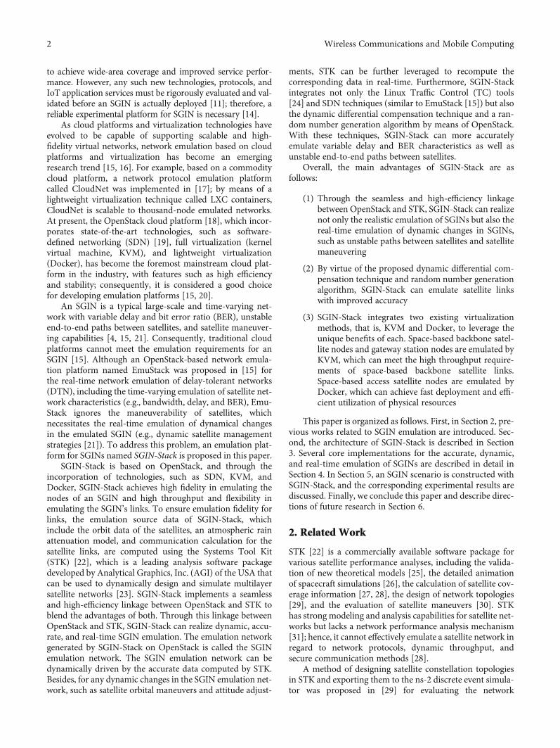
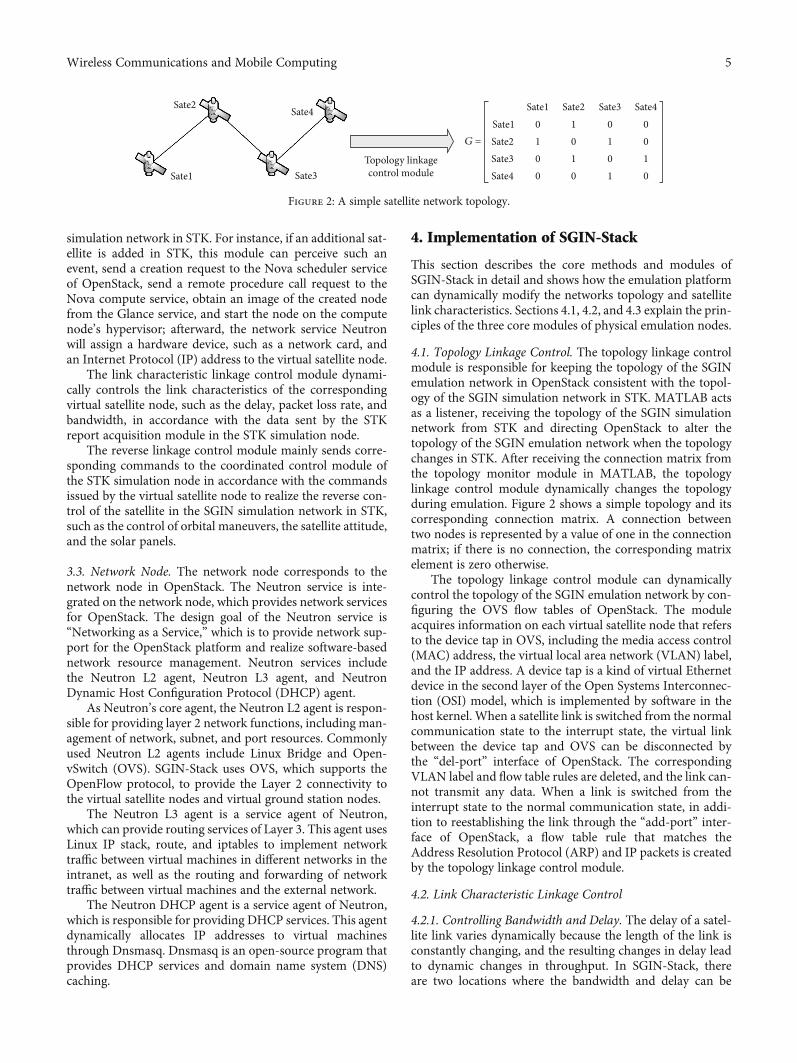
4.1. Topology Linkage Control. The topology linkage controlmodule is responsible for keeping the topology of the SGINemulation network in OpenStack consistent with the topol-ogy of the SGIN simulation network in STK. MATLAB actsas a listener, receiving the topology of the SGIN simulationnetwork from STK and directing OpenStack to alter thetopology of the SGIN emulation network when the topologychanges in STK. After receiving the connection matrix fromthe topology monitor module in MATLAB, the topologylinkage control module dynamically changes the topologyduring emulation. Figure 2 shows a simple topology and itscorresponding connection matrix. A connection betweentwo nodes is represented by a value of one in the connectionmatrix; if there is no connection, the corresponding matrixelement is zero otherwise.
The topology linkage control module can dynamicallycontrol the topology of the SGIN emulation network by con-figuring the OVS flow tables of OpenStack. The moduleacquires information on each virtual satellite node that refersto the device tap in OVS, including the media access control(MAC) address, the virtual local area network (VLAN) label,and the IP address. A device tap is a kind of virtual Ethernetdevice in the second layer of the Open Systems Interconnec-tion (OSI) model, which is implemented by software in thehost kernel. When a satellite link is switched from the normalcommunication state to the interrupt state, the virtual linkbetween the device tap and OVS can be disconnected bythe “del-port” interface of OpenStack. The correspondingVLAN label and flow table rules are deleted, and the link can-not transmit any data. When a link is switched from theinterrupt state to the normal communication state, in addi-tion to reestablishing the link through the “add-port” inter-face of OpenStack, a flow table rule that matches theAddress Resolution Protocol (ARP) and IP packets is createdby the topology linkage control module.
4.2. Link Characteristic Linkage Control
4.2.1. Controlling Bandwidth and Delay. The delay of a satel-lite link varies dynamically because the length of the link isconstantly changing, and the resulting changes in delay leadto dynamic changes in throughput. In SGIN-Stack, thereare two locations where the bandwidth and delay can be
Sate2
Sate1 Sate3
Sate4
Sate4
Sate4
Sate3
Sate3
Sate2
Sate2Sate1
0010
0101
1010
0100
Sate1
Topology linkagecontrol module
G =
Figure 2: A simple satellite network topology.
5Wireless Communications and Mobile Computing
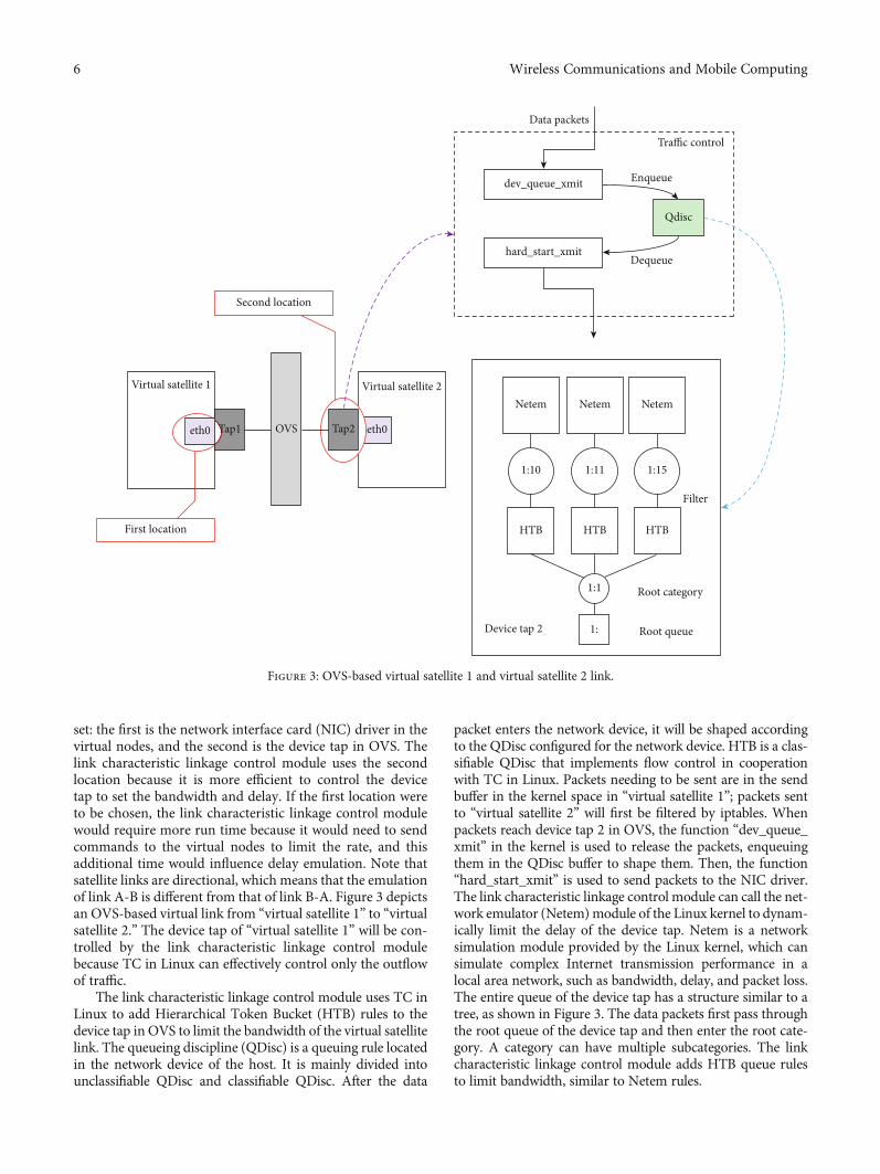
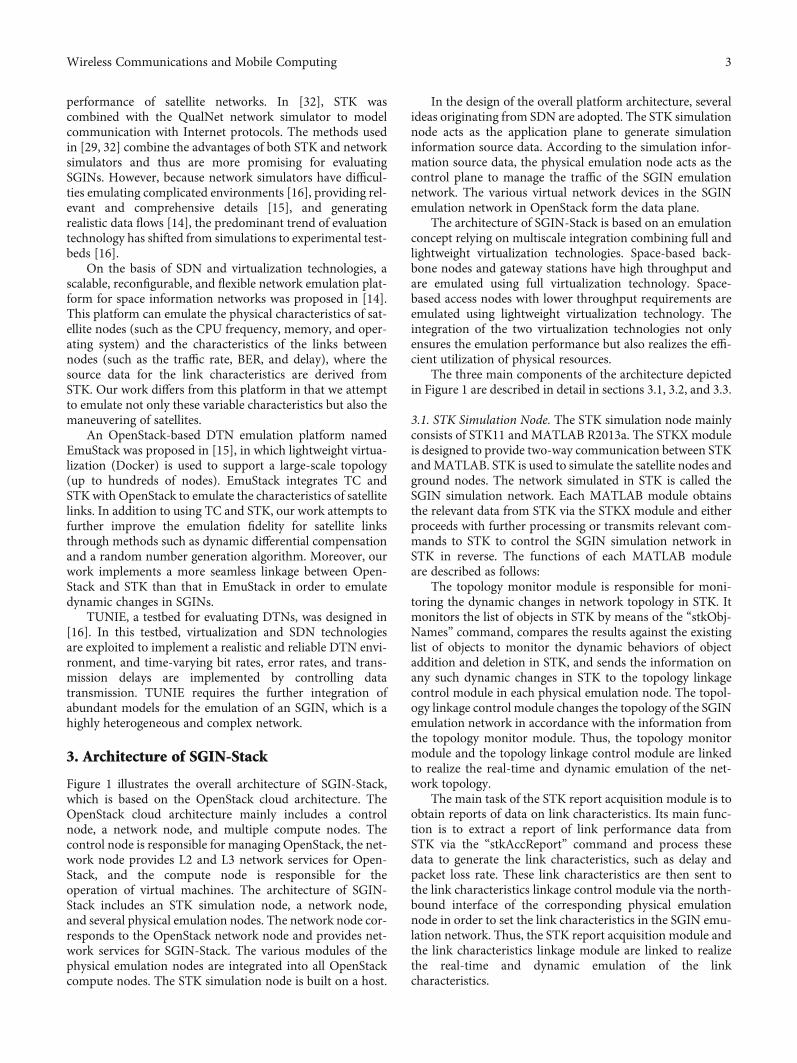
set: the first is the network interface card (NIC) driver in thevirtual nodes, and the second is the device tap in OVS. Thelink characteristic linkage control module uses the secondlocation because it is more efficient to control the devicetap to set the bandwidth and delay. If the first location wereto be chosen, the link characteristic linkage control modulewould require more run time because it would need to sendcommands to the virtual nodes to limit the rate, and thisadditional time would influence delay emulation. Note thatsatellite links are directional, which means that the emulationof link A-B is different from that of link B-A. Figure 3 depictsan OVS-based virtual link from “virtual satellite 1” to “virtualsatellite 2.” The device tap of “virtual satellite 1” will be con-trolled by the link characteristic linkage control modulebecause TC in Linux can effectively control only the outflowof traffic.
The link characteristic linkage control module uses TC inLinux to add Hierarchical Token Bucket (HTB) rules to thedevice tap in OVS to limit the bandwidth of the virtual satellitelink. The queueing discipline (QDisc) is a queuing rule locatedin the network device of the host. It is mainly divided intounclassifiable QDisc and classifiable QDisc. After the data
packet enters the network device, it will be shaped accordingto the QDisc configured for the network device. HTB is a clas-sifiable QDisc that implements flow control in cooperationwith TC in Linux. Packets needing to be sent are in the sendbuffer in the kernel space in “virtual satellite 1”; packets sentto “virtual satellite 2” will first be filtered by iptables. Whenpackets reach device tap 2 in OVS, the function “dev_queue_xmit” in the kernel is used to release the packets, enqueuingthem in the QDisc buffer to shape them. Then, the function“hard_start_xmit” is used to send packets to the NIC driver.The link characteristic linkage control module can call the net-work emulator (Netem)module of the Linux kernel to dynam-ically limit the delay of the device tap. Netem is a networksimulation module provided by the Linux kernel, which cansimulate complex Internet transmission performance in alocal area network, such as bandwidth, delay, and packet loss.The entire queue of the device tap has a structure similar to atree, as shown in Figure 3. The data packets first pass throughthe root queue of the device tap and then enter the root cate-gory. A category can have multiple subcategories. The linkcharacteristic linkage control module adds HTB queue rulesto limit bandwidth, similar to Netem rules.
Dequeue
eth0OVS Tap2Tap1
First location
Netem
Filter
Root queue
Root category
Device tap 2
HTB HTB HTB
1:15
1:
1:111:10
NetemNetemVirtual satellite 2Virtual satellite 1
Second location
hard_start_xmit
dev_queue_xmit
Qdisc
Enqueue
Traffic control
Data packets
1:1
eth0
Figure 3: OVS-based virtual satellite 1 and virtual satellite 2 link.
6 Wireless Communications and Mobile Computing
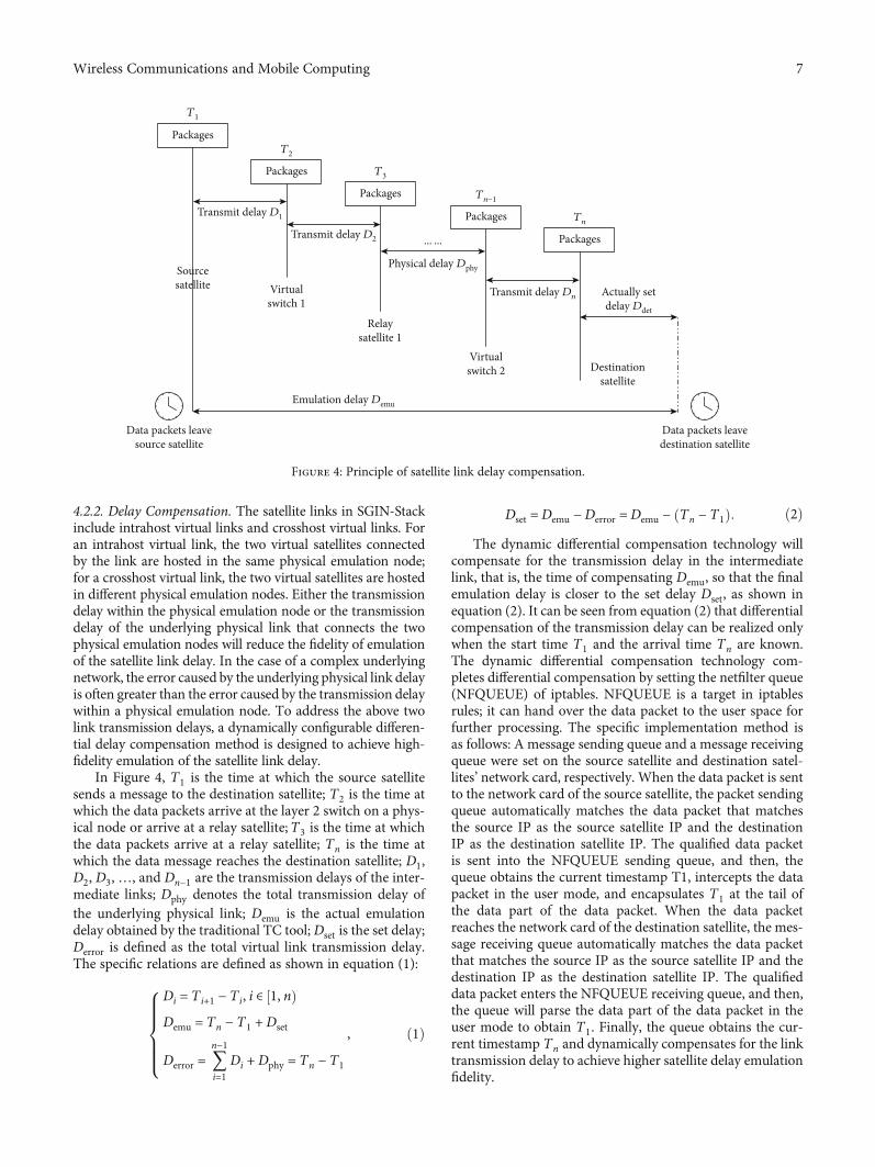
4.2.2. Delay Compensation. The satellite links in SGIN-Stackinclude intrahost virtual links and crosshost virtual links. Foran intrahost virtual link, the two virtual satellites connectedby the link are hosted in the same physical emulation node;for a crosshost virtual link, the two virtual satellites are hostedin different physical emulation nodes. Either the transmissiondelay within the physical emulation node or the transmissiondelay of the underlying physical link that connects the twophysical emulation nodes will reduce the fidelity of emulationof the satellite link delay. In the case of a complex underlyingnetwork, the error caused by the underlying physical link delayis often greater than the error caused by the transmission delaywithin a physical emulation node. To address the above twolink transmission delays, a dynamically configurable differen-tial delay compensation method is designed to achieve high-fidelity emulation of the satellite link delay.
In Figure 4, T1 is the time at which the source satellitesends a message to the destination satellite; T2 is the time atwhich the data packets arrive at the layer 2 switch on a phys-ical node or arrive at a relay satellite;T3 is the time at whichthe data packets arrive at a relay satellite; Tn is the time atwhich the data message reaches the destination satellite; D1,D2, D3,…, and Dn−1 are the transmission delays of the inter-mediate links; Dphy denotes the total transmission delay ofthe underlying physical link; Demu is the actual emulationdelay obtained by the traditional TC tool; Dset is the set delay;Derror is defined as the total virtual link transmission delay.The specific relations are defined as shown in equation (1):
Di = Ti+1 − Ti, i ∈ 1, n½ ÞDemu = Tn − T1 +Dset
Derror = 〠n−1
i=1Di +Dphy = Tn − T1
8>>>><
>>>>:
, ð1Þ
Dset =Demu −Derror =Demu − Tn − T1ð Þ: ð2ÞThe dynamic differential compensation technology will
compensate for the transmission delay in the intermediatelink, that is, the time of compensating Demu, so that the finalemulation delay is closer to the set delay Dset, as shown inequation (2). It can be seen from equation (2) that differentialcompensation of the transmission delay can be realized onlywhen the start time T1 and the arrival time Tn are known.The dynamic differential compensation technology com-pletes differential compensation by setting the netfilter queue(NFQUEUE) of iptables. NFQUEUE is a target in iptablesrules; it can hand over the data packet to the user space forfurther processing. The specific implementation method isas follows: A message sending queue and a message receivingqueue were set on the source satellite and destination satel-lites’ network card, respectively. When the data packet is sentto the network card of the source satellite, the packet sendingqueue automatically matches the data packet that matchesthe source IP as the source satellite IP and the destinationIP as the destination satellite IP. The qualified data packetis sent into the NFQUEUE sending queue, and then, thequeue obtains the current timestamp T1, intercepts the datapacket in the user mode, and encapsulates T1 at the tail ofthe data part of the data packet. When the data packetreaches the network card of the destination satellite, the mes-sage receiving queue automatically matches the data packetthat matches the source IP as the source satellite IP and thedestination IP as the destination satellite IP. The qualifieddata packet enters the NFQUEUE receiving queue, and then,the queue will parse the data part of the data packet in theuser mode to obtain T1. Finally, the queue obtains the cur-rent timestamp Tn and dynamically compensates for the linktransmission delay to achieve higher satellite delay emulationfidelity.
T1
Packages
Packages
Transmit delay D1
Transmit delay D2
Physical delay Dphy
Transmit delay Dn
Actually setdelay Ddet
Destinationsatellite
Data packets leavedestination satellite
Virtualswitch 2
Virtualswitch 1
Relaysatellite 1
Sourcesatellite
Data packets leavesource satellite
Emulation delay Demu
Packages
Packages
Packages... ...
T2
T3
Tn−1
Tn
Figure 4: Principle of satellite link delay compensation.
7Wireless Communications and Mobile Computing
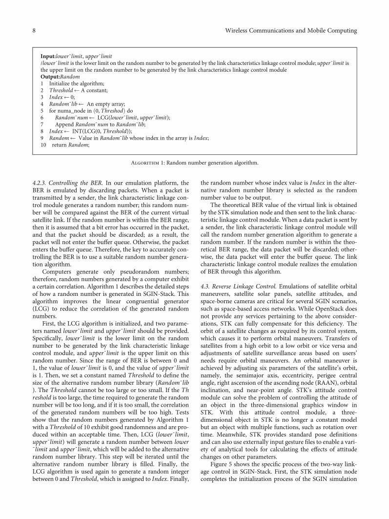
4.2.3. Controlling the BER. In our emulation platform, theBER is emulated by discarding packets. When a packet istransmitted by a sender, the link characteristic linkage con-trol module generates a random number; this random num-ber will be compared against the BER of the current virtualsatellite link. If the random number is within the BER range,then it is assumed that a bit error has occurred in the packet,and that the packet should be discarded; as a result, thepacket will not enter the buffer queue. Otherwise, the packetenters the buffer queue. Therefore, the key to accurately con-trolling the BER is to use a suitable random number genera-tion algorithm.
Computers generate only pseudorandom numbers;therefore, random numbers generated by a computer exhibita certain correlation. Algorithm 1 describes the detailed stepsof how a random number is generated in SGIN-Stack. Thisalgorithm improves the linear congruential generator(LCG) to reduce the correlation of the generated randomnumbers.
First, the LCG algorithm is initialized, and two parame-ters named lower¯limit and upper¯limit should be provided.Specifically, lower¯limit is the lower limit on the randomnumber to be generated by the link characteristic linkagecontrol module, and upper¯limit is the upper limit on thisrandom number. Since the range of BER is between 0 and1, the value of lower¯limit is 0, and the value of upper¯limitis 1. Then, we set a constant named Threshold to define thesize of the alternative random number library (Random¯lib). The Threshold cannot be too large or too small. If the Threshold is too large, the time required to generate the randomnumber will be too long, and if it is too small, the correlationof the generated random numbers will be too high. Testsshow that the random numbers generated by Algorithm 1with a Threshold of 10 exhibit good randomness and are pro-duced within an acceptable time. Then, LCG (lower¯limit,upper¯limit) will generate a random number between lower¯limit and upper¯limit, which will be added to the alternativerandom number library. This step will be iterated until thealternative random number library is filled. Finally, theLCG algorithm is used again to generate a random integerbetween 0 and Threshold, which is assigned to Index. Finally,
the random number whose index value is Index in the alter-native random number library is selected as the randomnumber value to be output.
The theoretical BER value of the virtual link is obtainedby the STK simulation node and then sent to the link charac-teristic linkage control module. When a data packet is sent bya sender, the link characteristic linkage control module willcall the random number generation algorithm to generate arandom number. If the random number is within the theo-retical BER range, the data packet will be discarded; other-wise, the data packet will enter the buffer queue. The linkcharacteristic linkage control module realizes the emulationof BER through this algorithm.
4.3. Reverse Linkage Control. Emulations of satellite orbitalmaneuvers, satellite solar panels, satellite attitudes, andspace-borne cameras are critical for several SGIN scenarios,such as space-based access networks. While OpenStack doesnot provide any services pertaining to the above consider-ations, STK can fully compensate for this deficiency. Theorbit of a satellite changes as required by its control system,which causes it to perform orbital maneuvers. Transfers ofsatellites from a high orbit to a low orbit or vice versa andadjustments of satellite surveillance areas based on users’needs require orbital maneuvers. An orbital maneuver isachieved by adjusting six parameters of the satellite’s orbit,namely, the semimajor axis, eccentricity, perigee centralangle, right ascension of the ascending node (RAAN), orbitalinclination, and near-point angle. STK’s attitude controlmodule can solve the problem of controlling the attitude ofan object in the three-dimensional graphics window inSTK. With this attitude control module, a three-dimensional object in STK is no longer a constant modelbut an object with multiple functions, such as rotation overtime. Meanwhile, STK provides standard pose definitionsand can also use externally input gesture files to enable a vari-ety of analytical tools for calculating the effects of attitudechanges on other parameters.
Figure 5 shows the specific process of the two-way link-age control in SGIN-Stack. First, the STK simulation nodecompletes the initialization process of the SGIN simulation
Input:lower¯limit, upper¯limit/lower¯limit is the lower limit on the random number to be generated by the link characteristics linkage control module; upper¯limit isthe upper limit on the random number to be generated by the link characteristics linkage control moduleOutput:Random1 Initialize the algorithm;2 Threshold←A constant;3 Index← 0;4 Random¯lib← An empty array;5 for numa_node in ð0, ThreshodÞ do6 Random¯num← LCG(lower¯limit, upper¯limit);7 Append Random¯num to Random¯lib;8 Index← INT(LCG(0, Threshold));9 Random← Value in Random¯lib whose index in the array is Index;10 return Random;
Algorithm 1: Random number generation algorithm.
8 Wireless Communications and Mobile Computing
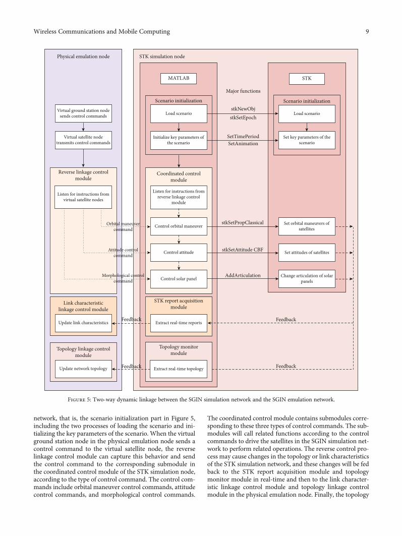
network, that is, the scenario initialization part in Figure 5,including the two processes of loading the scenario and ini-tializing the key parameters of the scenario. When the virtualground station node in the physical emulation node sends acontrol command to the virtual satellite node, the reverselinkage control module can capture this behavior and sendthe control command to the corresponding submodule inthe coordinated control module of the STK simulation node,according to the type of control command. The control com-mands include orbital maneuver control commands, attitudecontrol commands, and morphological control commands.
The coordinated control module contains submodules corre-sponding to these three types of control commands. The sub-modules will call related functions according to the controlcommands to drive the satellites in the SGIN simulation net-work to perform related operations. The reverse control pro-cess may cause changes in the topology or link characteristicsof the STK simulation network, and these changes will be fedback to the STK report acquisition module and topologymonitor module in real-time and then to the link character-istic linkage control module and topology linkage controlmodule in the physical emulation node. Finally, the topology
Physical emulation node STK simulation node
STK
Scenario initializationScenario initialization
Load scenarioLoad scenario
Set key parameters of thescenario
Listen for instructions fromreverse linkage control
module
Control orbital maneuver
Control attitude
Control solar panel
Extract real-time reports
Extract real-time topologyUpdate network topology
Update link characteristics
Orbital maneuvercommand
Attitude controlcommand
Morphological controlcommand
Topology linkage controlmodule
Link characteristiclinkage control module
Topology monitormodule
STK report acquisitionmodule
Initialize key parameters ofthe scenario SetAnimation
stkSetEpochstkNewObj
Major functions
MATLAB
Coordinated controlmodule
SetTimePeriod
stkSetAttitude CBF
AddArticulation
Feedback
FeedbackFeedback
Feedback
Change articulation of solarpanels
Set attitudes of satellites
Set orbital maneuvers ofsatellites
stkSetPropClassical
Reverse linkage controlmodule
Virtual ground station nodesends control commands
Virtual satellite nodetransmits control commands
Listen for instructions fromvirtual satellite nodes
Figure 5: Two-way dynamic linkage between the SGIN simulation network and the SGIN emulation network.
9Wireless Communications and Mobile Computing
and link characteristics in the SGIN emulation network willbe updated in real-time.
Let us take orbital maneuver control as an example. Theprocess is as follows: first, the reverse linkage control modulereceives a parameter adjustment command. Then, the coor-dinated control module receives the corresponding com-mand from the reverse linkage control module and uses thefunction “stkSetPropClassical” to control the orbital maneu-ver of the relevant satellite in the SGIN simulation network.As a result, SGIN-Stack updates the SGIN emulation net-work, including the network topology and virtual satellitelink characteristics, based on the new SGIN simulationnetwork.
5. Experiments
In this section, a typical SGIN topology is emulated using ourSGIN-Stack platform, and two experiments are performed.In the first experiment, the intermittence, bandwidth, delay,and BER of all links in an SGIN are emulated in real-timeto show the high fidelity of SGIN-Stack. In the second exper-iment, a simulation scenario considering satellite orbitalmaneuvers, attitudes, and solar panels is constructed to showthat SGIN-Stack can perform the dynamic and real-time net-work emulation for an SGIN.
5.1. A Typical SGIN Topology. We first describe a typicalSGIN topology that can meet the communication needs ofterrestrial users anywhere in the world. The topology consistsof a space-based backbone network, a space-based access net-work, and a ground network. Terrestrial users can connect tothe SGIN to make satellite phone calls and use navigationservices from anywhere via the space-based access network.The space-based backbone network is responsible for long-distance communication and information exchange.
According to the design requirements above, the designobjectives of the space-based backbone network and thespace-based access network are as follows:
(1) The space-based backbone network should bedesigned to cover the entire world and, in particular,be able to continuously cover China
(2) The space-based access network should be able tocover China and the surrounding areas and should
be easy for terrestrial users to access from anywhere,including high-latitude areas
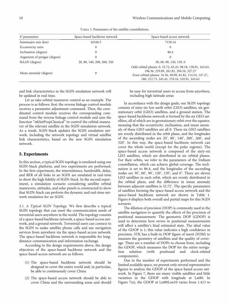
In accordance with the design goals, our SGIN topologyconsists of sixty-six low earth orbit (LEO) satellites, six geo-stationary orbit (GEO) satellites, and a ground station. Thespace-based backbone network is formed by the six GEO sat-ellites, all of which are in geostationary orbit over the equator,meaning that the eccentricity, inclination, and mean anom-aly of these GEO satellites are all 0. These six GEO satellitesare evenly distributed in the orbit plane, and the longitudesof the ascending nodes are 20°, 80°, 140°, 200°, 260°, and320°. In this way, the space-based backbone network cancover the whole world (except for the polar regions). Thespace-based access network is composed of the sixty-sixLEO satellites, which are distributed in six orbital planes.For their orbits, we refer to the parameters of the Iridiumconstellation, which can achieve global coverage. The incli-nation is set to 86.4, and the longitudes of the ascendingnodes are 30°, 60°, 90°, 120°, 150°, and 0°. There are elevenLEO satellites in each orbit, which are evenly distributed inthe orbital plane, and the difference in mean anomalybetween adjacent satellites is 32.72°. The specific parametersof satellites forming the space-based access network and thespace-based backbone network are shown in Table 1.Figure 6 displays both overall and partial maps for this SGINscenario.
The dilution of precision (DOP) is commonly used in thesatellite navigation to quantify the effects of the precision ofpositional measurement. The geometric DOP (GDOP) isused to determine how errors in positional measurementswill affect a satellite’s final estimated state. The ideal valueof the GDOP is 1; this value indicates a high confidence inprecision. STK has a built-in DOP figure of merit (FOM) tomeasure the geometry of satellites and the quality of cover-age. There are a number of DOPs to choose from, includingthe GDOP, which measures the DOP for the entire naviga-tion solution (with positional and clock-relatedcomponents).
Due to the number of experiments performed and thelimited available space, we present only several representativefigures to analyze the GDOP of the space-based access net-work. In Figure 7, there are many visible satellites and littlevariation in the GDOP with longitude at Lat80. InFigure 7(a), the GDOP at Lat80Lon10 varies from 1.413 to
Table 1: Parameters of the satellite constellations.
6∗parameters Space-based backbone network Space-based access network
Semimajor axis (km) 42166.3 7158.14
Eccentricity ratio 0 0
Inclination (degree) 0 86.4
Argument of perigee (degree) 0 0
RAAN (degree) 20, 80, 140, 200, 260, 320 30, 60, 90, 120, 150, 0
Mean anomaly (degree) 0
Odd orbital planes: 0, 32.72, 65.45, 98.18, 130.91, 163.63,196.36, 229.09, 261.82, 294.54, 327.27
Even orbital planes: 16.36, 49.09, 81.82, 114.54, 147.27,180, 212.73, 245.45, 278.18, 310.91, 343.63
10 Wireless Communications and Mobile Computing
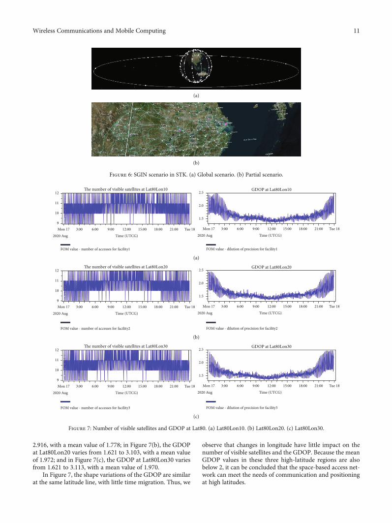
2.916, with a mean value of 1.778; in Figure 7(b), the GDOPat Lat80Lon20 varies from 1.621 to 3.103, with a mean valueof 1.972; and in Figure 7(c), the GDOP at Lat80Lon30 variesfrom 1.621 to 3.113, with a mean value of 1.970.
In Figure 7, the shape variations of the GDOP are similarat the same latitude line, with little time migration. Thus, we
observe that changes in longitude have little impact on thenumber of visible satellites and the GDOP. Because the meanGDOP values in these three high-latitude regions are alsobelow 2, it can be concluded that the space-based access net-work can meet the needs of communication and positioningat high latitudes.
Australia
Asia
(a)
(b)
Figure 6: SGIN scenario in STK. (a) Global scenario. (b) Partial scenario.
12
11
10
9Mon 17 3:00
2020 Aug6:00 9:00 12:00
Time (UTCG)
FOM value - number of accesses for facility1 FOM value - dilution of precision for facility1
�e number of visible satellites at Lat80Lon10 GDOP at Lat80Lon10
15:00 18:00 21:00 Tue 18
2.5
2.0
1.5
Mon 17 3:002020 Aug
6:00 9:00 12:00Time (UTCG)
15:00 18:00 21:00 Tue 18
(a)
12
11
10
9Mon 17 3:00
2020 Aug6:00 9:00 12:00
Time (UTCG)
FOM value - number of accesses for facility2 FOM value - dilution of precision for facility2
�e number of visible satellites at Lat80Lon20 GDOP at Lat80Lon20
15:00 18:00 21:00 Tue 18
2.5
2.0
1.5
Mon 17 3:002020 Aug
6:00 9:00 12:00Time (UTCG)
15:00 18:00 21:00 Tue 18
(b)
12
11
10
9Mon 17 3:00
2020 Aug6:00 9:00 12:00
Time (UTCG)
FOM value - number of accesses for facility3 FOM value - dilution of precision for facility3
�e number of visible satellites at Lat80Lon30 GDOP at Lat80Lon30
15:00 18:00 21:00 Tue 18
2.5
2.0
1.5
Mon 17 3:002020 Aug
6:00 9:00 12:00Time (UTCG)
15:00 18:00 21:00 Tue 18
(c)
Figure 7: Number of visible satellites and GDOP at Lat80. (a) Lat80Lon10. (b) Lat80Lon20. (c) Lat80Lon30.
11Wireless Communications and Mobile Computing
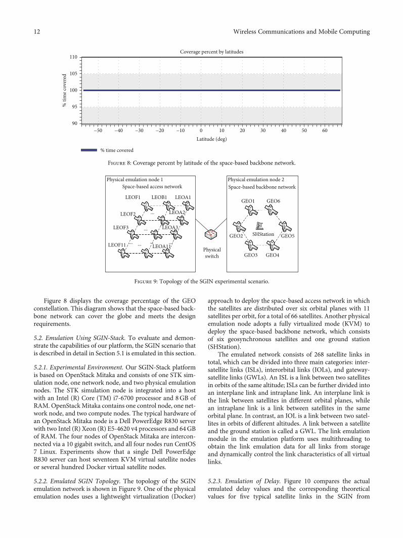
Figure 8 displays the coverage percentage of the GEOconstellation. This diagram shows that the space-based back-bone network can cover the globe and meets the designrequirements.
5.2. Emulation Using SGIN-Stack. To evaluate and demon-strate the capabilities of our platform, the SGIN scenario thatis described in detail in Section 5.1 is emulated in this section.
5.2.1. Experimental Environment. Our SGIN-Stack platformis based on OpenStack Mitaka and consists of one STK sim-ulation node, one network node, and two physical emulationnodes. The STK simulation node is integrated into a hostwith an Intel (R) Core (TM) i7-6700 processor and 8GB ofRAM. OpenStackMitaka contains one control node, one net-work node, and two compute nodes. The typical hardware ofan OpenStack Mitaka node is a Dell PowerEdge R830 serverwith two Intel (R) Xeon (R) E5-4620 v4 processors and 64GBof RAM. The four nodes of OpenStack Mitaka are intercon-nected via a 10 gigabit switch, and all four nodes run CentOS7 Linux. Experiments show that a single Dell PowerEdgeR830 server can host seventeen KVM virtual satellite nodesor several hundred Docker virtual satellite nodes.
5.2.2. Emulated SGIN Topology. The topology of the SGINemulation network is shown in Figure 9. One of the physicalemulation nodes uses a lightweight virtualization (Docker)
approach to deploy the space-based access network in whichthe satellites are distributed over six orbital planes with 11satellites per orbit, for a total of 66 satellites. Another physicalemulation node adopts a fully virtualized mode (KVM) todeploy the space-based backbone network, which consistsof six geosynchronous satellites and one ground station(SHStation).
The emulated network consists of 268 satellite links intotal, which can be divided into three main categories: inter-satellite links (ISLs), interorbital links (IOLs), and gateway-satellite links (GWLs). An ISL is a link between two satellitesin orbits of the same altitude; ISLs can be further divided intoan interplane link and intraplane link. An interplane link isthe link between satellites in different orbital planes, whilean intraplane link is a link between satellites in the sameorbital plane. In contrast, an IOL is a link between two satel-lites in orbits of different altitudes. A link between a satelliteand the ground station is called a GWL. The link emulationmodule in the emulation platform uses multithreading toobtain the link emulation data for all links from storageand dynamically control the link characteristics of all virtuallinks.
5.2.3. Emulation of Delay. Figure 10 compares the actualemulated delay values and the corresponding theoreticalvalues for five typical satellite links in the SGIN from
Coverage percent by latitudes110
105
95% ti
me c
over
ed
90−50
% time covered
−40 −30 −20 −10 0Latitude (deg)
10 20 30 40 50 60
100
Figure 8: Coverage percent by latitude of the space-based backbone network.
...
Physical emulation node 1 Physical emulation node 2Space-based access network Space-based backbone network
LEOF1
LEOF2
LEOF3
LEOF11 LEOA11 Physicalswitch GEO3 GEO4
SHStation GEO5GEO2
GEO1 GEO6
LEOA3
LEOA2
LEOB1 LEOA1
...
...... ... ...
Figure 9: Topology of the SGIN experimental scenario.
12 Wireless Communications and Mobile Computing
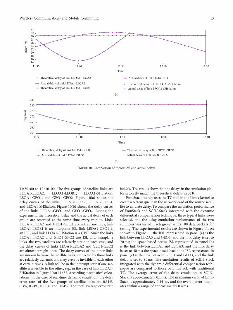
11: 30 : 00 to 12 : 10 : 00. The five groups of satellite links areLEOA1-LEOA2, LEOA1-LEOB1, LEOA1-SHStation,LEOA1-GEO1, and GEO1-GEO2. Figure 10(a) shows thedelay curves of the links LEOA1-LEOA2, LEOA1-LEOB1,and LEOA1-SHStaiton. Figure 10(b) shows the delay curvesof the links LEOA1-GEO1 and GEO1-GEO2. During theexperiment, the theoretical delay and the actual delay of eachgroup are recorded at the same time every minute. LinksLEOA1-LEOA2 and GEO1-GEO2 are intraplane ISLs, linkLEOA1-LEOB1 is an interplane ISL, link LEOA1-GEO1 isan IOL, and link LEOA1-SHStation is a GWL. Since the linksLEOA1-LEOA2 and GEO1-GEO2 are ISL and intraplanelinks, the two satellites are relatively static in each case, andthe delay curves of links LEOA1-LEOA2 and GEO1-GEO2are almost straight lines. The delay curves of the other linksare uneven because the satellite pairs connected by those linksare relatively dynamic and may even be invisible to each otherat certain times. A link will be in the interrupt state if one sat-ellite is invisible to the other, e.g., in the case of link LEOA1-SHStation in Figure 10 at 11 : 52. According to statistical calcu-lations, in the case of real-time dynamic emulation, the delayerror rates of the five groups of satellite links are 0.31%,0.3%, 0.24%, 0.11%, and 0.04%. The total average error rate
is 0.2%. The results show that the delays in the emulation plat-form closely match the theoretical delays in STK.
EmuStack merely uses the TC tool in the Linux kernel tocreate a Netem queue in the network card of the source satel-lite to emulate delay. To compare the emulation performanceof EmuStack and SGIN-Stack integrated with the dynamicdifferential compensation technique, three typical links wereselected, and the delay emulation performance of the twosolutions was tested. Each group sends 100 data packets fortesting. The experimental results are shown in Figure 11. Asshown in Figure 11, the IOL represented in panel (a) is thelink between LEOA3 and GEO3, and the link delay is set to70ms; the space-based access ISL represented in panel (b)is the link between LEOA1 and LEOA3, and the link delayis set to 40ms; the space-based backbone ISL represented inpanel (c) is the link between GEO1 and GEO3, and the linkdelay is set to 80ms. The emulation results of SGIN-Stackintegrated with the dynamic differential compensation tech-nique are compared to those of EmuStack with traditionalTC. The average error of the delay emulation in SGIN-Stack is approximately 0.1ms. The maximum error of Emu-Stack is approximately 0.44ms, and the overall error fluctu-ates within a range of approximately 0.4ms.
Del
ay (m
s)3432302826242220181614
11:30 11:40 11:50Time
12:00
�eoretical delay of link LEOA1-SHStationActual delay of link LEOA1-SHStation�eoretical delay of link LEOA1-LEOB1
Actual delay of link LEOA1-LEOB1�eoretical delay of link LEOA1-LEOA2
Actual delay of link LEOA1-LEOA2
12:10
(a)
285
280
275
265
260
255
270
Time
�eoretical delay of link LEOA1-GEO1
Actual delay of link LEOA1-GEO1
11:30 11:40 11:50 12:00 12:10
Del
ay (m
s)
�eoretical delay of link GEO1-GEO2Actual delay of link GEO1-GEO2
(b)
Figure 10: Comparison of theoretical and actual delays.
13Wireless Communications and Mobile Computing
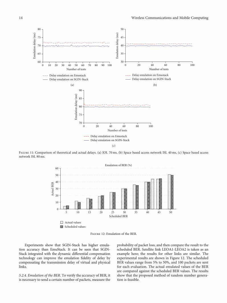
Experiments show that SGIN-Stack has higher emula-tion accuracy than EmuStack. It can be seen that SGIN-Stack integrated with the dynamic differential compensationtechnology can improve the emulation fidelity of delay bycompensating the transmission delay of virtual and physicallinks.
5.2.4. Emulation of the BER. To verify the accuracy of BER, itis necessary to send a certain number of packets, measure the
probability of packet loss, and then compare the result to thescheduled BER. Satellite link LEOA1-LEOA2 is taken as anexample here; the results for other links are similar. Theexperimental results are shown in Figure 12. The scheduledBER values range from 5% to 50%, and 100 packets are sentfor each evaluation. The actual emulated values of the BERare compared against the scheduled BER values. The resultsshow that the proposed method of random number genera-tion is feasible.
Number of tests
Emul
atio
n de
lay
(ms)
060
65
70
75
80
10 20 30 40 50 60 70 80 90 100
Delay emulation on EmustackDelay emulation on SGIN-Stack
(a)
300 20 40 60
Number of tests80 100
35
40
45
50
Emul
atio
n de
lay (m
s)
Delay emulation on EmustackDelay emulation on SGIN-Stack
(b)
700 20 40 60
Number of tests80 100
75
80
85
90
Emul
atio
n de
lay
(ms)
Delay emulation on EmustackDelay emulation on SGIN-Stack
(c)
Figure 11: Comparison of theoretical and actual delays. (a) IOL 70ms, (b) Space based access network ISL 40ms, (c) Space based accessnetwork ISL 80ms.
50
10
20
30
40
Actu
al B
ER
50
60
10 15 20 25 30Scheduled BER
Emulation of BER (%)
Actual valuesScheduled values
35 40 45 50
Figure 12: Emulation of the BER.
14 Wireless Communications and Mobile Computing
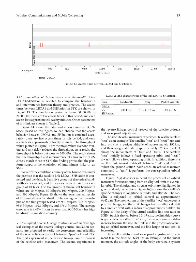
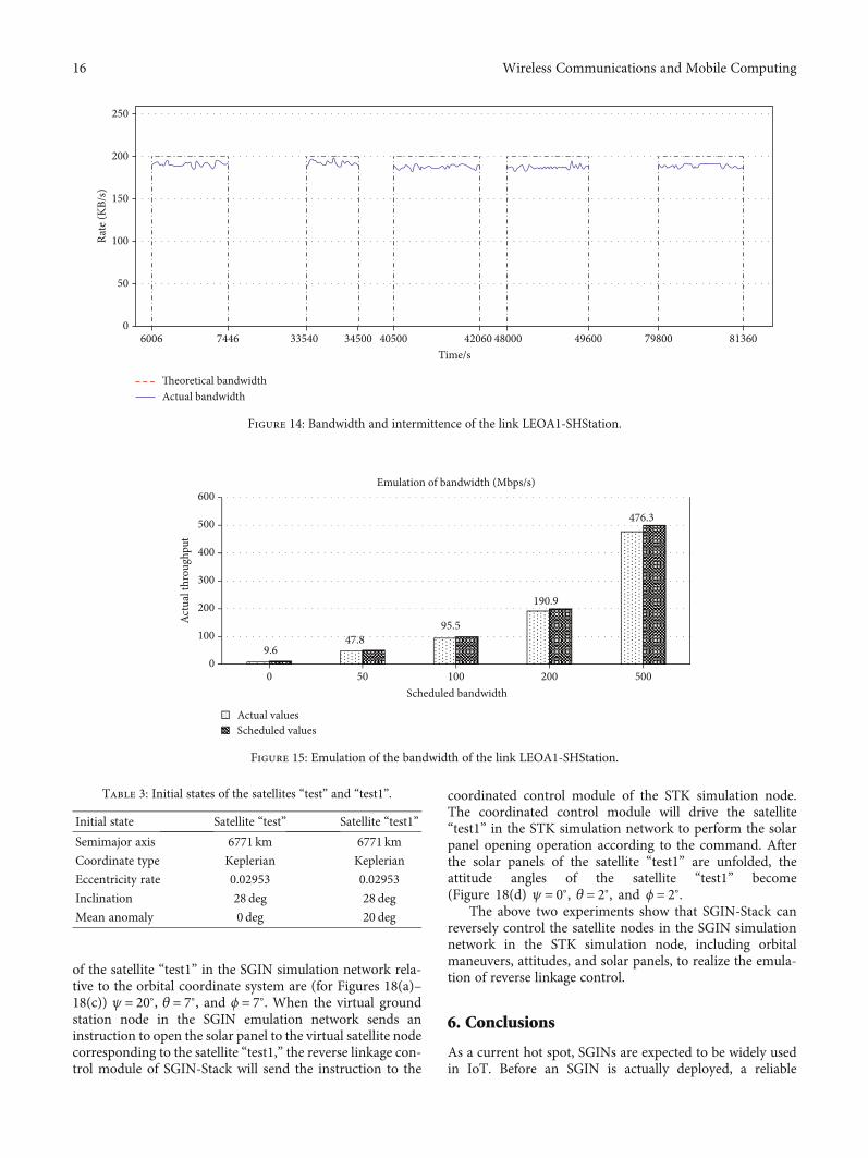
5.2.5. Emulation of Intermittence and Bandwidth. LinkLEOA1-SHStation is selected to compare the bandwidthand intermittence between theory and practice. The accesstimes between LEOA1 and SHStation in STK are shown inFigure 13. The emulation period is from 00 : 00 : 00 to24 : 00 : 00; there are five access times in this period, and eachaccess lasts approximately twenty minutes. Other parametersof this link are shown in Table 2.
Figure 14 shows the rates and access times on SGIN-Stack. Based on this figure, we can observe that the accessbehavior between LEOA1 and SHStation is emulated accu-rately; there are five access times in this period, and eachaccess lasts approximately twenty minutes. The throughputvalues plotted in Figure 14 are the mean values over one min-ute, and any delay reduces the throughput. As a result, thethroughput is below but close to 200 kB/s. The result showsthat the throughput and intermittence of a link in the SGINclosely match those in STK; this finding proves that the plat-form supports the emulation of intermittent links in anSGIN.
To verify the emulation accuracy of the bandwidth, underthe premise that the satellite link LEOA1-SHStation is con-nected and the delay is 0ms, five groups of theoretical band-width values are set, and the average value is taken for eachgroup of 10 tests. The five groups of theoretical bandwidthvalues are 10 Mbps/s, 50 Mbps/s, 100 Mbps/s, 200 Mbps/s,and 500 Mbps/s. Figure 15 shows the experimental resultsof the emulation of bandwidth. The average actual through-put of the five groups tested are 9.6 Mbps/s, 47.8 Mbps/s,95.5 Mbps/s, 190.9 Mbps/s, and 476.3 Mbps/s. The averageerror rate is 4.43%. It can be seen that SGIN-Stack has highbandwidth simulation accuracy.
5.3. Example of Reverse Linkage Control Emulation. Two typ-ical examples of the reverse linkage control emulation sce-nario are proposed to verify the correctness and reliabilityof the reverse linkage control between OpenStack and STK.The first experiment is the reverse linkage control processof the satellite orbit maneuver. The second experiment is
the reverse linkage control process of the satellite attitudeand solar panel adjustment.
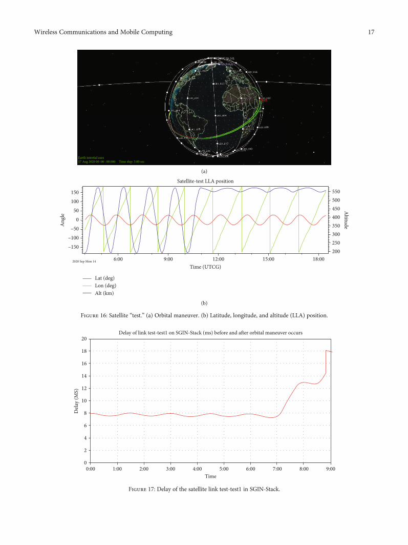
The satellite orbit maneuver experiment takes the satellite“test” as an example. The satellite “test” and “test1” are sentinto orbit at a perigee altitude of approximately 192 km,and their apogee altitude is approximately 570 km. Table 3shows the initial states of “test” and “test1.” The satellite“test” initially follows a fixed operating orbit, and “test1”always follows a fixed operating orbit. In addition, there is asatellite link named test-test1 between “test” and “test1.”When the ground station node sends an orbital maneuvercommand to “test,” it performs the corresponding orbitalmaneuver.
Figure 16(a) describes in detail the process of an orbitalmaneuver for transitioning from an elliptical orbit to a circu-lar orbit. The elliptical and circular orbits are highlighted ingreen and red, respectively. Figure 16(b) shows the satellite’sspecific changes in longitude, latitude, and altitude. The sat-ellite is subjected to orbital control at approximately6 : 45 a.m. The momentum of the satellite “test” undergoes apositive change, and the orbit changes from an elliptical orbitto a circular orbit with a radius of approximately 570 km. InFigure 17, the delay of the virtual satellite link test-test1 inSGIN-Stack is shown: before 10 : 45 a.m., the link delay curveis gentle, whereas after 10 : 45 a.m., the curve shows a suddenincrease because the satellite “test” is in the process of execut-ing an orbital maneuver, and the link length of test-test1 isincreasing.
The satellite attitude and solar panel adjustment experi-ment take the satellite “test1” as an example. At the initialmoment, the attitude angles of the body coordinate system
3:00
17 A
ug 2
020
00:0
0:00
0
6:00 9:00 12:00Time (UTCG)
Tim
es
2020 Aug Mon 1715:00 18:00 21:00 Tue 18
Times (UTCG)
Figure 13: Access times between LEOA1 and SHStation.
Table 2: Link characteristics of the link LEOA1-SHStation.
Link Bandwidth Delay Packet loss rate
LEOA1=>SHStation
200 kB/s 8ms to 17ms 0% to 1%
15Wireless Communications and Mobile Computing
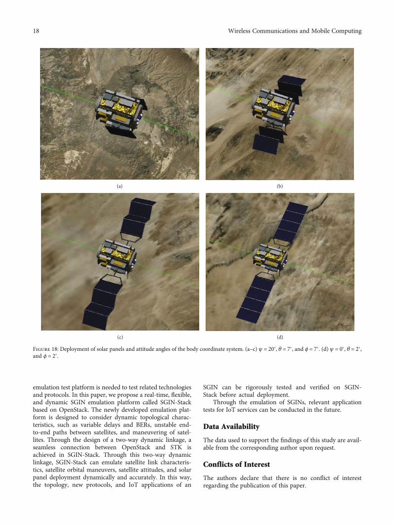
of the satellite “test1” in the SGIN simulation network rela-tive to the orbital coordinate system are (for Figures 18(a)–18(c)) ψ = 20∘, θ = 7∘, and ϕ = 7∘. When the virtual groundstation node in the SGIN emulation network sends aninstruction to open the solar panel to the virtual satellite nodecorresponding to the satellite “test1,” the reverse linkage con-trol module of SGIN-Stack will send the instruction to the
coordinated control module of the STK simulation node.The coordinated control module will drive the satellite“test1” in the STK simulation network to perform the solarpanel opening operation according to the command. Afterthe solar panels of the satellite “test1” are unfolded, theattitude angles of the satellite “test1” become(Figure 18(d) ψ = 0∘, θ = 2∘, and ϕ = 2∘.
The above two experiments show that SGIN-Stack canreversely control the satellite nodes in the SGIN simulationnetwork in the STK simulation node, including orbitalmaneuvers, attitudes, and solar panels, to realize the emula-tion of reverse linkage control.
6. Conclusions
As a current hot spot, SGINs are expected to be widely usedin IoT. Before an SGIN is actually deployed, a reliable
06006 7446 33540 34500 40500 42060
Time/s48000 49600 79800 81360
50
100
150
200
Rate
(KB/
s)250
�eoretical bandwidthActual bandwidth
Figure 14: Bandwidth and intermittence of the link LEOA1-SHStation.
0Scheduled bandwidth
Emulation of bandwidth (Mbps/s)
Actual values
0
100
200
300
Actu
al th
roug
hput
400
500
600
200 500
476.3
190.9
95.547.8
9.6
50 100
Scheduled values
Figure 15: Emulation of the bandwidth of the link LEOA1-SHStation.
Table 3: Initial states of the satellites “test” and “test1”.
Initial state Satellite “test” Satellite “test1”
Semimajor axis 6771 km 6771 km
Coordinate type Keplerian Keplerian
Eccentricity rate 0.02953 0.02953
Inclination 28 deg 28 deg
Mean anomaly 0 deg 20 deg
16 Wireless Communications and Mobile Computing
Earth intertial axes17 Aug 2020 00 :00 : 00.000 Time step: 3.00 sec
Test1
(a)
–150–100
6:002020 Sep Mon 14 9:00 12:00Time (UTCG)
Satellite-test LLA position
Lat (deg)Lon (deg)Alt (km)
15:00 18:00200250300350
Altitude
400450500550
–50
Ang
le
050
100150
(b)
Figure 16: Satellite “test.” (a) Orbital maneuver. (b) Latitude, longitude, and altitude (LLA) position.
0:000
2
4
6
8
10
12
Del
ay (M
S)
14
16
18
20
1:00 2:00 3:00 4:00 5:00Time
Delay of link test-test1 on SGIN-Stack (ms) before and a�er orbital maneuver occurs
6:00 7:00 8:00 9:00
Figure 17: Delay of the satellite link test-test1 in SGIN-Stack.
17Wireless Communications and Mobile Computing
emulation test platform is needed to test related technologiesand protocols. In this paper, we propose a real-time, flexible,and dynamic SGIN emulation platform called SGIN-Stackbased on OpenStack. The newly developed emulation plat-form is designed to consider dynamic topological charac-teristics, such as variable delays and BERs, unstable end-to-end paths between satellites, and maneuvering of satel-lites. Through the design of a two-way dynamic linkage, aseamless connection between OpenStack and STK isachieved in SGIN-Stack. Through this two-way dynamiclinkage, SGIN-Stack can emulate satellite link characteris-tics, satellite orbital maneuvers, satellite attitudes, and solarpanel deployment dynamically and accurately. In this way,the topology, new protocols, and IoT applications of an
SGIN can be rigorously tested and verified on SGIN-Stack before actual deployment.
Through the emulation of SGINs, relevant applicationtests for IoT services can be conducted in the future.
Data Availability
The data used to support the findings of this study are avail-able from the corresponding author upon request.
Conflicts of Interest
The authors declare that there is no conflict of interestregarding the publication of this paper.
(a) (b)
(c) (d)
Figure 18: Deployment of solar panels and attitude angles of the body coordinate system. (a–c) ψ = 20∘, θ = 7∘, and ϕ = 7∘. (d) ψ = 0∘, θ = 2∘,and ϕ = 2∘.
18 Wireless Communications and Mobile Computing
Acknowledgments
This work was supported by the National Natural ScienceFoundation of China [grant numbers 61972182, 61672264]and the National Key R&D Program of China [grant number2016YFB0800305].
References
[1] Z. Yi, X. Du, Y. Liao, and L. Cao, “A quality-of-service-awaredynamic evolution model for space–ground integrated net-work,” International Journal of Distributed Sensor Networks,vol. 13, no. 8, Article ID 155014771772864, 2017.
[2] Y. Xiao, T. Zhang, and L. Liu, “Addressing subnet divisionbased on geographical information for satellite-ground inte-grated network,” IEEE Access, vol. 6, pp. 75824–75833,2018.
[3] Y. Shi, Y. Cao, J. Liu, and N. Kato, “A cross-domain SDNarchitecture for multi-layered space-terrestrial integrated net-works,” IEEE Network, vol. 33, no. 1, pp. 29–35, 2019.
[4] I. A. Alimi, A. L. Teixeira, and P. P. Monteiro, “Effects ofcorrelated multivariate FSO channel on outage perfor-mance of space-air-ground integrated network (SAGIN),”Wireless Personal Communications, vol. 106, no. 1, pp. 7–25, 2019.
[5] Y.Wang, J. Yang, X. Guo, and Z. Qu, “Satellite edge computingfor the Internet of Things in aerospace,” Sensors, vol. 19,no. 20, article 4375, 2019.
[6] X. Cheng, F. Lyu, W. Quan et al., “Space/aerial-assisted com-puting offloading for IoT applications: a learning-basedapproach,” IEEE Journal on Selected Areas in Communica-tions, vol. 37, no. 5, pp. 1117–1129, 2019.
[7] M. De Sanctis, E. Cianca, G. Araniti, I. Bisio, and R. Prasad,“Satellite communications supporting internet of remotethings,” IEEE Internet of Things Journal, vol. 3, no. 1,pp. 113–123, 2016.
[8] Z. Qu, G. Zhang, H. Cao, and J. Xie, “LEO satellite constella-tion for Internet of Things,” IEEE Access, vol. 5, pp. 18391–18401, 2017.
[9] K. L. A. Yau, A. R. Syed, W. Hashim, J. Qadir, C. Wu, andN. Hassan, “Maritime networking: bringing internet to thesea,” IEEE Access, vol. 7, pp. 48236–48255, 2019.
[10] T. Hong, W. Zhao, R. Liu, and M. Kadoch, “Space-air-groundIoT network and related key technologies,” IEEE WirelessCommunications, vol. 27, no. 2, pp. 96–104, 2020.
[11] J. Liu, Y. Shi, Z. M. Fadlullah, and N. Kato, “Space-air-groundintegrated network: a survey,” IEEE Communications Surveys& Tutorials, vol. 20, no. 4, pp. 2714–2741, 2018.
[12] B. Zhao, P. Liu, X.Wang, and I. You, “Toward efficient authen-tication for space-air-ground integrated Internet of things,”International Journal of Distributed Sensor Networks, vol. 15,no. 7, Article ID 155014771986039, 2019.
[13] X. Liu, X. Zhai, W. Lu, and C. Wu, “QoS-Guarantee ResourceAllocation for Multibeam Satellite Industrial Internet ofThings with NOMA,” IEEE Transactions on Industrial Infor-matics, p. 1, 2019.
[14] T. Lu, W. Zhang, X. Ni et al., “A scalable network emulationarchitecture for space internetworking,” in 2016 IEEE Interna-tional Conference on Communication Systems (ICCS), pp. 1–5,Shenzhen, China, December 2016.
[15] H. Li, H. Zhou, H. Zhang, B. Feng, and W. Shi, “Emustack: anopenstack-based dtn network emulation platform (extendedversion),” Mobile Information Systems, vol. 2016, 15 pages,2016.
[16] Y. Li, P. Hui, D. Jin, and S. Chen, “Delay-tolerant network pro-tocol testing and evaluation,” IEEE Communications Maga-zine, vol. 53, no. 1, pp. 258–266, 2015.
[17] A. Dutta and O. Gnawali, “Large-scale network protocol emu-lation on commodity cloud,” in 2014 IEEE Global Communi-cations Conference, pp. 1114–1119, Austin, TX, USA,December 2014.
[18] Openstackhttp://www.openstack.org/.
[19] S.-h. Zhang, X.-x. Meng, and L.-h. Wang, “SDNForensics: acomprehensive forensics framework for software defined net-work,” in Proceedings of the International Conference on Com-puter Networks and Communication Technology (CNCT 2016),Atlantis Press, December 2016.
[20] X. Wang, M. Zhai, and G. Zhang, “Research on high-fidelityrouter emulation technologies based on cloud platform,” in2018 IEEE 7th International Conference on Cloud Networking(CloudNet), pp. 1–4, Tokyo, Japan, October 2018.
[21] T. Li, H. Zhou, H. Luo, and S. Yu, “SeRvICE: a software definedframework for integrated space-terrestrial satellite communi-cation,” IEEE Transactions on Mobile Computing, vol. 17,no. 3, pp. 703–716, 2018.
[22] Stkhttps://agi.com/products.
[23] J. Qi, Z. Li, and G. Liu, “Research on coverage and link ofmulti-layer Satellite Network based on STK,” in 2015 10thInternational Conference on Communications and Networkingin China (ChinaCom), pp. 410–415, Shanghai, China, August2015.
[24] B. Hubert, Linux advanced routing & traffic control HOWTO,vol. 1, Netherlabs BV, 2002.
[25] F. Xhafa, X. Herrero, A. Barolli, L. Barolli, andM. Takizawa, “Evaluation of struggle strategy in geneticalgorithms for ground stations scheduling problem,” Journalof Computer and System Sciences, vol. 79, no. 7, pp. 1086–1100, 2013.
[26] S. McCamish andM. Romano, “Simulation of relative multiplespacecraft dynamics and control with MATLAB-SIMULINKand Satellite Tool Kit,” in AIAA Modeling and SimulationTechnologies Conference and Exhibit, p. 6805, Hilton Head,SC, USA, June 2007.
[27] V. B. S. S. I. Dutt, G. S. B. Rao, S. S. Rani, S. R. Babu,R. Goswami, and C. U. Kumari, “Investigation of GDOP forprecise user position computation with all satellites in viewand optimum four satellite configurations,” The Journal ofIndian Geophysical Union, vol. 13, no. 3, pp. 139–148, 2009.
[28] S. C. Spangelo, J. W. Cutler, A. T. Klesh, and D. R. Boone,“Models and tools to evaluate space communication networkcapacity,” IEEE Transactions on Aerospace and Electronic Sys-tems, vol. 48, no. 3, pp. 2387–2404, 2012.
[29] P. Muri, J. McNair, J. Antoon, A. Gordon-Ross, K. Cason, andN. Fitz-Coy, “Topology design and performance analysis fornetworked earth observing small satellites,” in 2011-MILCOM2011Military Communications Conference, p. 1940, Baltimore,MD, USA, November 2011.
[30] M. Yin, J. Li, X. Wang, and H. Baoyin, “A rapid method forvalidation and visualization of agile earth-observation satel-lites scheduling,” Astrodynamics, vol. 2, no. 4, pp. 325–337,2018.
19Wireless Communications and Mobile Computing
[31] A. N. U. Medina and G. Qiang, “QoS routing for LEO satellitenetworks,” in Pervasive Computing and the Networked World.ICPCA/SWS 2012. Lecture Notes in Computer Science, vol7719, Q. Zu, B. Hu, and A. Elçi, Eds., pp. 482–494, Springer,Berlin, Heidelberg, 2012.
[32] D. R. Beering, S. Tseng, J. L. Hayden et al., “RF communicationdata model for satellite networks,” in MILCOM 2009-2009IEEE Military Communications Conference, pp. 1–7, Boston,MA, USA, October 2009.
20 Wireless Communications and Mobile Computing