Embed Size (px)
Citation preview
HAL Id: hal-02810846https://hal.archives-ouvertes.fr/hal-02810846
Submitted on 6 Jun 2020
HAL is a multi-disciplinary open accessarchive for the deposit and dissemination of sci-entific research documents, whether they are pub-lished or not. The documents may come fromteaching and research institutions in France orabroad, or from public or private research centers.
L’archive ouverte pluridisciplinaire HAL, estdestinée au dépôt et à la diffusion de documentsscientifiques de niveau recherche, publiés ou non,émanant des établissements d’enseignement et derecherche français ou étrangers, des laboratoirespublics ou privés.
Experimental Investigation of a Platform Damper withCurved Contact Areas
Martin Jareland
To cite this version:Martin Jareland. Experimental Investigation of a Platform Damper with Curved Contact Areas.ASME 2001 International Design Engineering Technical Conferences and Computers and Informationin Engineering Conference, Sep 2001, Pittsburgh, United States. �hal-02810846�
EXPERIMENTAL INVESTIGATION OF A PLATFORM DAMPERWITH CURVED CONTACT AREAS
Martin H. JarelandLinköping University
Dept. of Mechanical EngineeringSE-581 83 Linköping, Sweden
E-mail: [email protected]
ABSTRACTThis paper presents a set of experiments which have been
performed with a new friction damper for a high pressure turbine. Themain objective of these experiments was to tune a simulation model forthe current damper. The simulation model used is valid for bothmicroslip and macroslip. A number of other topics were alsoinvestigated, such as influence of glued platforms, repeatability of anexperiment, comparison of new and used dampers, and the change insurface structure of the contact areas.
A similar set of experiments has been performed earlier with thecurrent damper. On that occasion, it was found that the experiments andsimulations did not agree as desired and therefore a new set ofexperiments was suggested. This paper presents the new experimentsand the new simulations with a more precisely tuned model. Thesimulation model is tuned by selecting a suitable coefficient of frictionand tangential stiffness for the contact interface model. It is found thatthe simulations agree well with the experimental results when thenormal force is held constant and the excitation force is varied. Theproperties of the contact, contact area and pressure, are unchanged whenthe normal force is constant.
If a new damper is compared with a damper that has been used in aseries of experiments, it is found that the resonance shifts to a lowerfrequency and that the amplitude increases. This is probably caused bya decrease in coefficient of friction due to wear of the contact surfaces.
The repeatability of an experiment has been investigated by runningthe same experiment five times in succession. It was found that therepeatability was very good if the position of the damper was notchanged. The differences that were found were mainly due to wear onthe contact surfaces. A comparison of sweeping forward or backward infrequency was also performed. It showed that the difference was smallboth for experiments with small motions in the contacts and forexperiments with a high amount of macroslip.
1
INTRODUCTIONOne of the main problems with jet engines in service is high-cycle
fatigue of turbine blades due to resonance vibrations within theoperating range of the engine. A number of actions can be taken toincrease the reliability of the turbine: improve the material properties ofthe blades, design the blades to avoid resonance vibrations, modify theflow through the turbine and finally, increase the amount of damping inthe system. This paper focuses on the use of friction damping to improvethe life of turbine blades. Other types of damping that exist in a turbinestage are material and aeroelastic damping. The proportion of each typeof damping in the relation to the total amount of damping may varygreatly between different turbines and different running conditions.
A number of methods can be used to increase the amount of frictiondamping in a bladed disk, see the review of friction damping in bladeddisks by Griffin [1]. In a turbine stage, the most common method is touse a specific damping device, in the form of a piece of metal arrangedin a cavity underneath the platform of the blades. The friction damper ispressed against two adjacent platforms by centrifugal force when theturbine is running. Friction damping arises when a relative motionoccurs between the blades. This type of damper is also often called aplatform damper due to its position underneath the platforms.
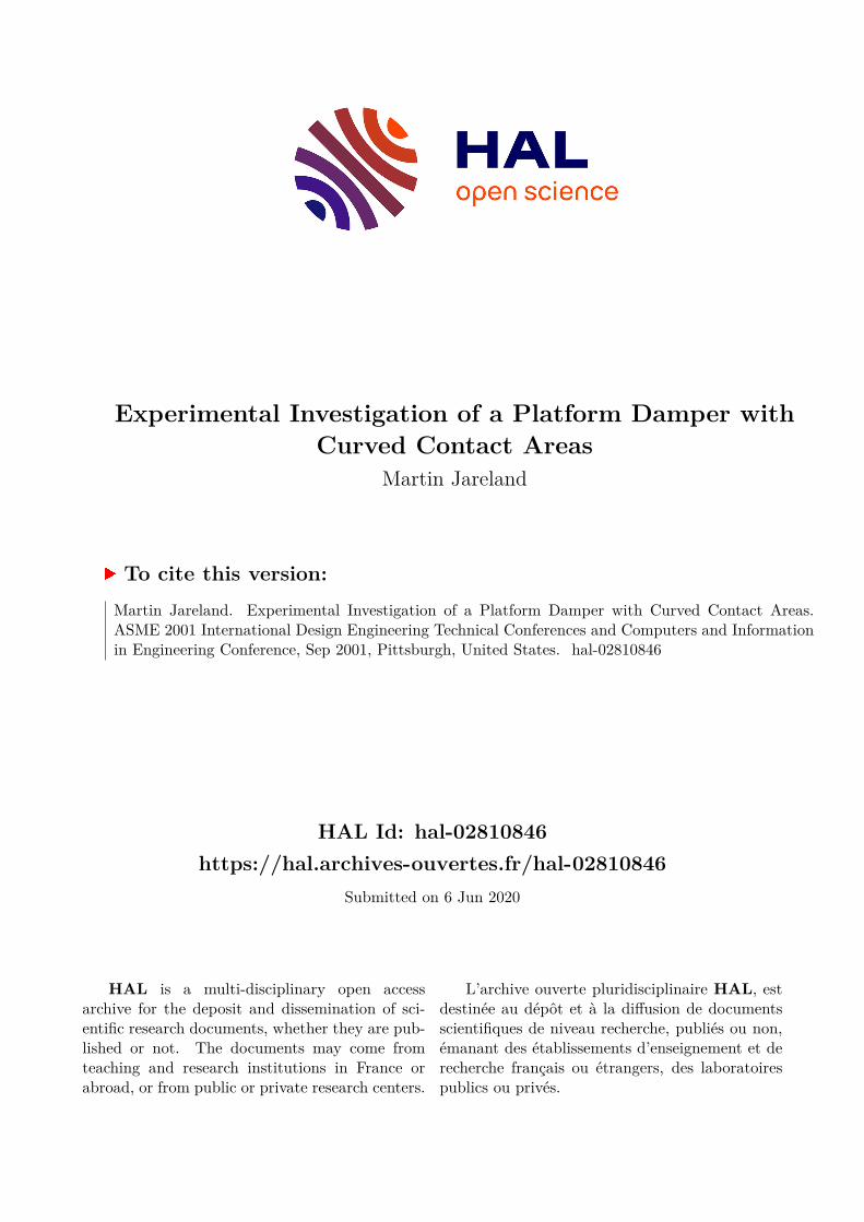
The damper studied in the current paper is a so-called curved wedgedamper. The configuration of the platforms and the current blade-to-blade damper is shown in Fig. 1. The characteristics of this configurationare that the platforms have an inclined contact area and the contactsurfaces on the damper are curved. The inclination of the platformsmakes the damper self-centering when centrifugal force is acting on it.
Turbine stages with platform dampers have been studied by anumber of researchers, both theoretically and experimentally. The mostcommonly used simulation model for friction contacts is the macroslipmodel, which implies that the contact is either stuck or fully slipping.This model has been used by Muszynska and Jones [2], Griffin [3] andYang and Menq [4,5]. For a platform damper, the displacements aresmall and the normal force high. It is therefore most likely that partial
2
modifications of the test procedure were recommended in the evaluationand a new series of experiments was suggested. The two main questionsthat arose in the evaluation of the experiments were:
• Does the glue, which was used to mount the platforms on thebeams, provide damping to the system? To investigate this, a newset of beams with soldered platforms was manufactured. Due to thefact that solder provides a lower amount of material damping thanpolymers in general.
• The properties of the contacts are changed when the normal forceis changed. How will this influence the result? It is thereforesuggested that instead the normal force be kept constant and theexcitation force varied.
The main objective of this new series of experiments is to investigatethese topics. A number of other topics are also investigated, such asrepeatability of an experiment, comparison of new and used dampers,and changes in the surface structure of the contact areas.
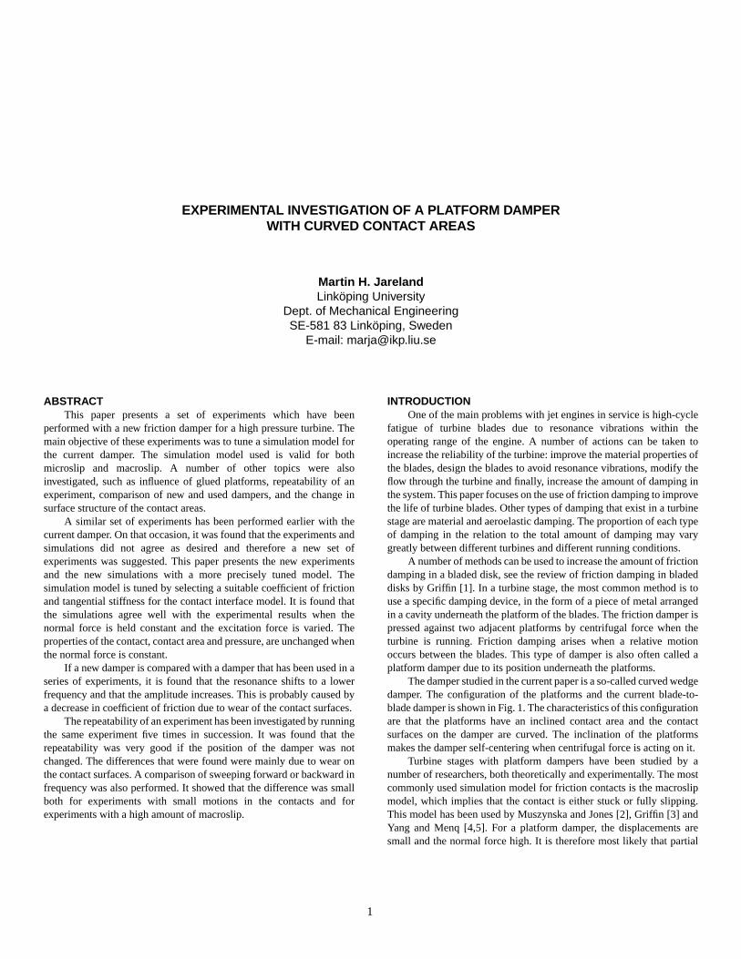
EXPERIMENT SET-UPA schematic view of the test rig is shown in Fig. 2 and a photo in
Fig. 3. A more detailed description of the test rig can be found in Csaba[9] and therefore only a brief presentation is given here. The test rigconsists of two beams clamped to an inertia block, which is located ona frame foundation with rubber in between. The damper is locatedbetween the blades and loaded with a weight against the platforms. Theplatforms are made of the same material as the real blade platforms. Twosets of beams have been used: one set with the platforms glued on andone set with the platforms soldered on.
To check how well these two sets of beams are tuned, a modalanalysis of the system, without the damper, was performed. It was foundthat the out-of-phase natural frequency is located at 530.2 Hz and the in-phase mode at 544.4 Hz for the beams with glued platforms. For thebeams with soldered platforms the out-of-phase mode is at 509.5 Hz andthe in-phase mode at 522.6 Hz. It is also found that the damping in thesystem, without the damper, for the out-of-phase mode is approximately0.015% and 0.07% for the glued and soldered platforms, respectively.
Figure 2 Beam-Damper-Beam test rig.
Shaker
Forcetransducer
Acc1Acc2
M
Glued or solderedplatforms
slip will occur in the contact, which is denoted microslip. Thisphenomenon has been included in dynamic analysis of turbine stages byresearchers such as Csaba [6], Menq et al. [7] and Sanliturk et al. [8].Platform dampers have also been modelled with discrete frictioninterface models based on the Hertzian solution, see Csaba [9], Sextroet al. [10] and Panning et al. [11].
BACKGROUNDA new damper has been designed at Volvo Aero Corporation for the
RM8B HP-turbine. This damper has been tested in spin-pit tests and inengine tests by Volvo Aero Corporation. Csaba and Andersson [12]studied the current damper both theoretically and in spin-pit tests to findthe optimal damper mass. They modelled the friction interfaces with theBar model developed by Csaba [13], which is valid for both microslipand macroslip. The same friction interface model has been used byJareland and Csaba [14] to study mistuning of a bladed disk due tovariations in the properties of the dampers.
A new friction interface model for curved friction contacts has beendeveloped in a research project at Linköping University, Sweden, byCsaba [9]. This is a discrete friction interface model and is denoted theBrush model. The properties of the discrete contact points are based onthe Hertzian solution for the contact. This model is valid for bothmicroslip and macroslip, which is important in modelling platformdampers. A disadvantage of the Bar model is that it can only be used forcases with motion in a single dimension. The Brush model is suitablewhen a more general motion is present in the contact.
In order to verify the Brush model, experiments were carried out atImperial College, London, see Csaba [9]. These experiments wereperformed as part of the research program Mechanical FrictionDamping, which was financially supported by the Rolls-RoyceAerospace Group and Volvo Aero Corporation. The research wascarried out at the Imperial College of Science, Technology andMedicine, Centre of Vibration Engineering and Linköping University,Mechanical Engineering Department, Division of Machine Design.
During the evaluation of the experimental results, it was found thatthe simulations and experiments did not agree as desired. Differences inboth resonance frequency and amplitude were found. Some
Figure 1 A schematic view of a bladed disk with curved wedgedampers.
Blade
Friction damper
Disk
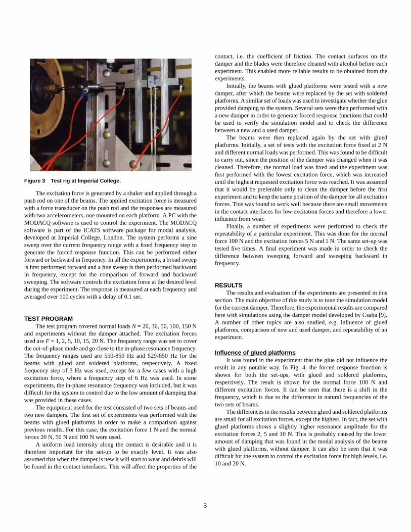
The excitation force is generated by a shaker and applied through apush rod on one of the beams. The applied excitation force is measuredwith a force transducer on the push rod and the responses are measuredwith two accelerometers, one mounted on each platform. A PC with theMODACQ software is used to control the experiment. The MODACQsoftware is part of the ICATS software package for modal analysis,developed at Imperial College, London. The system performs a sinesweep over the current frequency range with a fixed frequency step togenerate the forced response function. This can be performed eitherforward or backward in frequency. In all the experiments, a broad sweepis first performed forward and a fine sweep is then performed backwardin frequency, except for the comparison of forward and backwardsweeping. The software controls the excitation force at the desired levelduring the experiment. The response is measured at each frequency andaveraged over 100 cycles with a delay of 0.1 sec.
TEST PROGRAMThe test program covered normal loads N = 20, 36, 50, 100, 150 N
and experiments without the damper attached. The excitation forcesused are F = 1, 2, 5, 10, 15, 20 N. The frequency range was set to coverthe out-of-phase mode and go close to the in-phase resonance frequency.The frequency ranges used are 550-850 Hz and 529-850 Hz for thebeams with glued and soldered platforms, respectively. A fixedfrequency step of 3 Hz was used, except for a few cases with a highexcitation force, where a frequency step of 6 Hz was used. In someexperiments, the in-phase resonance frequency was included, but it wasdifficult for the system to control due to the low amount of damping thatwas provided in these cases.
The equipment used for the test consisted of two sets of beams andtwo new dampers. The first set of experiments was performed with thebeams with glued platforms in order to make a comparison againstprevious results. For this case, the excitation force 1 N and the normalforces 20 N, 50 N and 100 N were used.
A uniform load intensity along the contact is desirable and it istherefore important for the set-up to be exactly level. It was alsoassumed that when the damper is new it will start to wear and debris willbe found in the contact interfaces. This will affect the properties of the
Figure 3 Test rig at Imperial College.
3
contact, i.e. the coefficient of friction. The contact surfaces on thedamper and the blades were therefore cleaned with alcohol before eachexperiment. This enabled more reliable results to be obtained from theexperiments.
Initially, the beams with glued platforms were tested with a newdamper, after which the beams were replaced by the set with solderedplatforms. A similar set of loads was used to investigate whether the glueprovided damping to the system. Several sets were then performed witha new damper in order to generate forced response functions that couldbe used to verify the simulation model and to check the differencebetween a new and a used damper.
The beams were then replaced again by the set with gluedplatforms. Initially, a set of tests with the excitation force fixed at 2 Nand different normal loads was performed. This was found to be difficultto carry out, since the position of the damper was changed when it wascleaned. Therefore, the normal load was fixed and the experiment wasfirst performed with the lowest excitation force, which was increaseduntil the highest requested excitation force was reached. It was assumedthat it would be preferable only to clean the damper before the firstexperiment and to keep the same position of the damper for all excitationforces. This was found to work well because there are small movementsin the contact interfaces for low excitation forces and therefore a lowerinfluence from wear.
Finally, a number of experiments were performed to check therepeatability of a particular experiment. This was done for the normalforce 100 N and the excitation forces 5 N and 1 N. The same set-up wastested five times. A final experiment was made in order to check thedifference between sweeping forward and sweeping backward infrequency.
RESULTSThe results and evaluation of the experiments are presented in this
section. The main objective of this study is to tune the simulation modelfor the current damper. Therefore, the experimental results are comparedhere with simulations using the damper model developed by Csaba [9].A number of other topics are also studied, e.g. influence of gluedplatforms, comparison of new and used damper, and repeatability of anexperiment.
Influence of glued platformsIt was found in the experiment that the glue did not influence the
result in any notable way. In Fig. 4, the forced response function isshown for both the set-ups, with glued and soldered platforms,respectively. The result is shown for the normal force 100 N anddifferent excitation forces. It can be seen that there is a shift in thefrequency, which is due to the difference in natural frequencies of thetwo sets of beams.
The differences in the results between glued and soldered platformsare small for all excitation forces, except the highest. In fact, the set withglued platforms shows a slightly higher resonance amplitude for theexcitation forces 2, 5 and 10 N. This is probably caused by the loweramount of damping that was found in the modal analysis of the beamswith glued platforms, without damper. It can also be seen that it wasdifficult for the system to control the excitation force for high levels, i.e.10 and 20 N.
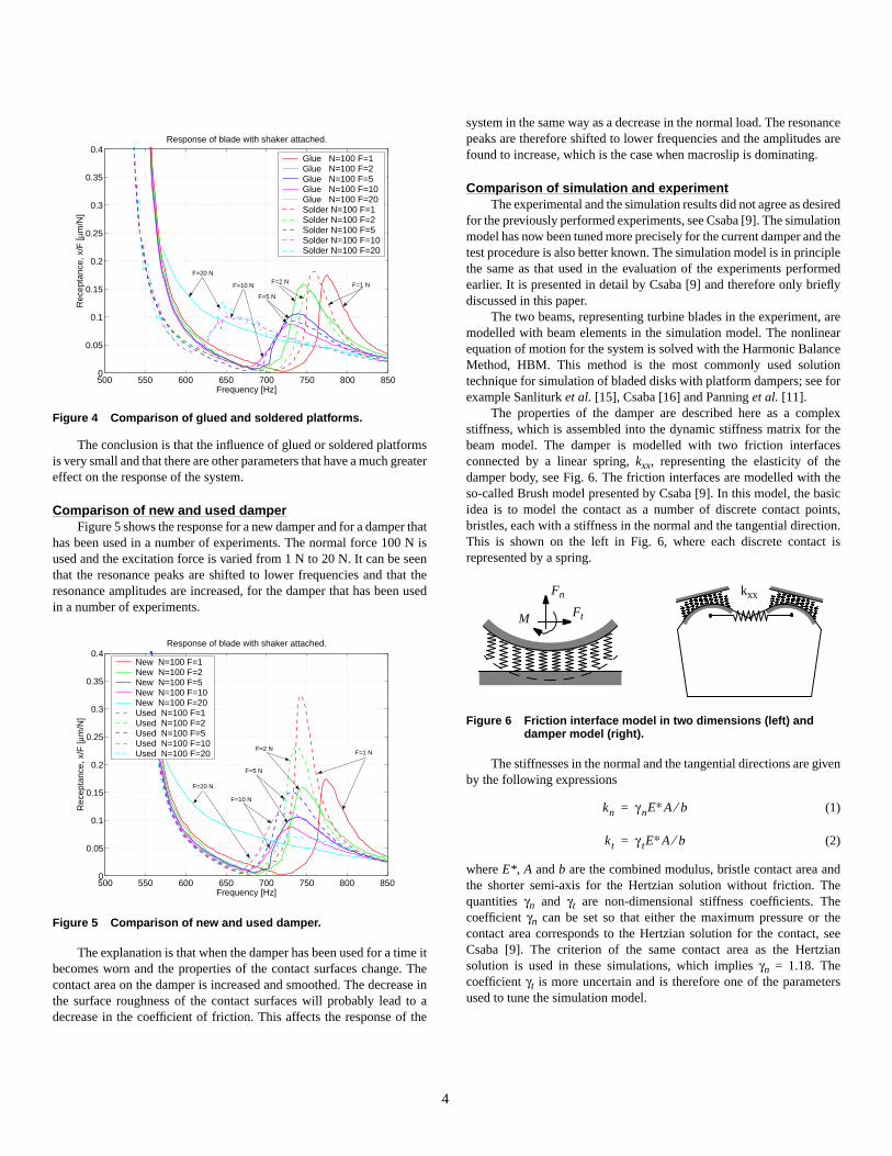
The conclusion is that the influence of glued or soldered platformsis very small and that there are other parameters that have a much greatereffect on the response of the system.
Comparison of new and used damperFigure 5 shows the response for a new damper and for a damper that
has been used in a number of experiments. The normal force 100 N isused and the excitation force is varied from 1 N to 20 N. It can be seenthat the resonance peaks are shifted to lower frequencies and that theresonance amplitudes are increased, for the damper that has been usedin a number of experiments.
The explanation is that when the damper has been used for a time itbecomes worn and the properties of the contact surfaces change. Thecontact area on the damper is increased and smoothed. The decrease inthe surface roughness of the contact surfaces will probably lead to adecrease in the coefficient of friction. This affects the response of the
Figure 4 Comparison of glued and soldered platforms.
Figure 5 Comparison of new and used damper.
500 550 600 650 700 750 800 8500
0.05
0.1
0.15
0.2
0.25
0.3
0.35
0.4
Rec
epta
nce,
x/F
[µm
/N]
Frequency [Hz]
Response of blade with shaker attached.
Glue N=100 F=1 Glue N=100 F=2 Glue N=100 F=5 Glue N=100 F=10Glue N=100 F=20Solder N=100 F=1 Solder N=100 F=2 Solder N=100 F=5 Solder N=100 F=10Solder N=100 F=20
F=1 N F=2 N
F=5 N
F=10 N
F=20 N
500 550 600 650 700 750 800 8500
0.05
0.1
0.15
0.2
0.25
0.3
0.35
0.4
Rec
epta
nce,
x/F
[µm
/N]
Frequency [Hz]
Response of blade with shaker attached.
New N=100 F=1 New N=100 F=2 New N=100 F=5 New N=100 F=10 New N=100 F=20 Used N=100 F=1 Used N=100 F=2 Used N=100 F=5 Used N=100 F=10Used N=100 F=20 F=1 N
F=2 N
F=5 N
F=10 N
F=20 N
4
system in the same way as a decrease in the normal load. The resonancepeaks are therefore shifted to lower frequencies and the amplitudes arefound to increase, which is the case when macroslip is dominating.
Comparison of simulation and experimentThe experimental and the simulation results did not agree as desired
for the previously performed experiments, see Csaba [9]. The simulationmodel has now been tuned more precisely for the current damper and thetest procedure is also better known. The simulation model is in principlethe same as that used in the evaluation of the experiments performedearlier. It is presented in detail by Csaba [9] and therefore only brieflydiscussed in this paper.
The two beams, representing turbine blades in the experiment, aremodelled with beam elements in the simulation model. The nonlinearequation of motion for the system is solved with the Harmonic BalanceMethod, HBM. This method is the most commonly used solutiontechnique for simulation of bladed disks with platform dampers; see forexample Sanliturk et al. [15], Csaba [16] and Panning et al. [11].
The properties of the damper are described here as a complexstiffness, which is assembled into the dynamic stiffness matrix for thebeam model. The damper is modelled with two friction interfacesconnected by a linear spring, kxx, representing the elasticity of thedamper body, see Fig. 6. The friction interfaces are modelled with theso-called Brush model presented by Csaba [9]. In this model, the basicidea is to model the contact as a number of discrete contact points,bristles, each with a stiffness in the normal and the tangential direction.This is shown on the left in Fig. 6, where each discrete contact isrepresented by a spring.
The stiffnesses in the normal and the tangential directions are givenby the following expressions
(1)
(2)
where E*, A and b are the combined modulus, bristle contact area andthe shorter semi-axis for the Hertzian solution without friction. Thequantities γn and γt are non-dimensional stiffness coefficients. Thecoefficient γn can be set so that either the maximum pressure or thecontact area corresponds to the Hertzian solution for the contact, seeCsaba [9]. The criterion of the same contact area as the Hertziansolution is used in these simulations, which implies γn = 1.18. Thecoefficient γt is more uncertain and is therefore one of the parametersused to tune the simulation model.
Figure 6 Friction interface model in two dimensions (left) anddamper model (right).
Fn
FtM
kxx
kn γ nE∗A b⁄=
kt γ tE∗A b⁄=
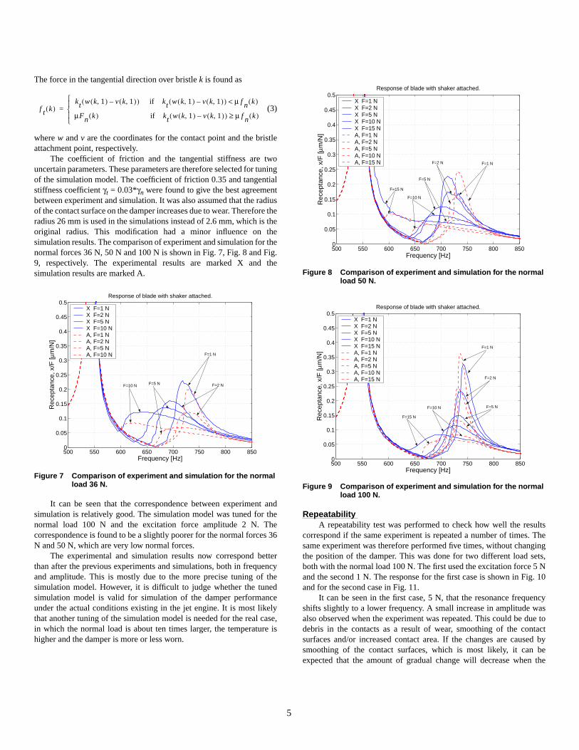
The force in the tangential direction over bristle k is found as
(3)
where w and v are the coordinates for the contact point and the bristleattachment point, respectively.
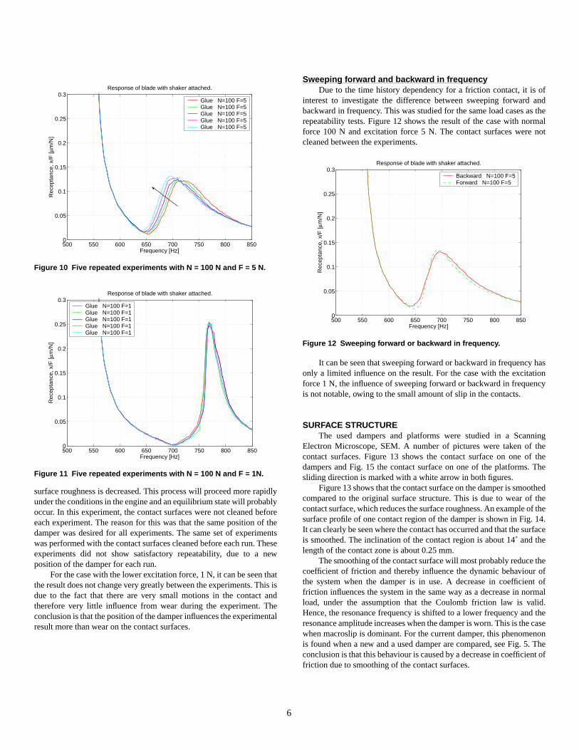
The coefficient of friction and the tangential stiffness are twouncertain parameters. These parameters are therefore selected for tuningof the simulation model. The coefficient of friction 0.35 and tangentialstiffness coefficient γt = 0.03*γn were found to give the best agreementbetween experiment and simulation. It was also assumed that the radiusof the contact surface on the damper increases due to wear. Therefore theradius 26 mm is used in the simulations instead of 2.6 mm, which is theoriginal radius. This modification had a minor influence on thesimulation results. The comparison of experiment and simulation for thenormal forces 36 N, 50 N and 100 N is shown in Fig. 7, Fig. 8 and Fig.9, respectively. The experimental results are marked X and thesimulation results are marked A.
It can be seen that the correspondence between experiment andsimulation is relatively good. The simulation model was tuned for thenormal load 100 N and the excitation force amplitude 2 N. Thecorrespondence is found to be a slightly poorer for the normal forces 36N and 50 N, which are very low normal forces.
The experimental and simulation results now correspond betterthan after the previous experiments and simulations, both in frequencyand amplitude. This is mostly due to the more precise tuning of thesimulation model. However, it is difficult to judge whether the tunedsimulation model is valid for simulation of the damper performanceunder the actual conditions existing in the jet engine. It is most likelythat another tuning of the simulation model is needed for the real case,in which the normal load is about ten times larger, the temperature ishigher and the damper is more or less worn.
Figure 7 Comparison of experiment and simulation for the normalload 36 N.
f t k( )kt w k 1,( ) v k 1,( )–( ) if kt w k 1,( ) v k 1,( )–( ) µ f n k( )<
µFn k( ) if kt w k 1,( ) v k 1,( )–( ) µ f n k( )≥
=
500 550 600 650 700 750 800 8500
0.05
0.1
0.15
0.2
0.25
0.3
0.35
0.4
0.45
0.5
Rec
epta
nce,
x/F
[µm
/N]
Frequency [Hz]
Response of blade with shaker attached.
X F=1 N X F=2 N X F=5 N X F=10 NA, F=1 N A, F=2 N A, F=5 N A, F=10 N F=1 N
F=2 N F=5 N F=10 N
5
RepeatabilityA repeatability test was performed to check how well the results
correspond if the same experiment is repeated a number of times. Thesame experiment was therefore performed five times, without changingthe position of the damper. This was done for two different load sets,both with the normal load 100 N. The first used the excitation force 5 Nand the second 1 N. The response for the first case is shown in Fig. 10and for the second case in Fig. 11.
It can be seen in the first case, 5 N, that the resonance frequencyshifts slightly to a lower frequency. A small increase in amplitude wasalso observed when the experiment was repeated. This could be due todebris in the contacts as a result of wear, smoothing of the contactsurfaces and/or increased contact area. If the changes are caused bysmoothing of the contact surfaces, which is most likely, it can beexpected that the amount of gradual change will decrease when the
Figure 8 Comparison of experiment and simulation for the normalload 50 N.
Figure 9 Comparison of experiment and simulation for the normalload 100 N.
500 550 600 650 700 750 800 8500
0.05
0.1
0.15
0.2
0.25
0.3
0.35
0.4
0.45
0.5
Rec
epta
nce,
x/F
[µm
/N]
Frequency [Hz]
Response of blade with shaker attached.
X F=1 N X F=2 N X F=5 N X F=10 NX F=15 NA, F=1 N A, F=2 N A, F=5 N A, F=10 NA, F=15 N F=1 N F=2 N
F=5 N
F=15 N
F=10 N
500 550 600 650 700 750 800 8500
0.05
0.1
0.15
0.2
0.25
0.3
0.35
0.4
0.45
0.5R
ecep
tanc
e, x
/F [µ
m/N
]
Frequency [Hz]
Response of blade with shaker attached.
X F=1 N X F=2 N X F=5 N X F=10 NX F=15 NA, F=1 N A, F=2 N A, F=5 N A, F=10 NA, F=15 N
F=1 N
F=2 N
F=5 N
F=15 N
F=10 N
surface roughness is decreased. This process will proceed more rapidlyunder the conditions in the engine and an equilibrium state will probablyoccur. In this experiment, the contact surfaces were not cleaned beforeeach experiment. The reason for this was that the same position of thedamper was desired for all experiments. The same set of experimentswas performed with the contact surfaces cleaned before each run. Theseexperiments did not show satisfactory repeatability, due to a newposition of the damper for each run.
For the case with the lower excitation force, 1 N, it can be seen thatthe result does not change very greatly between the experiments. This isdue to the fact that there are very small motions in the contact andtherefore very little influence from wear during the experiment. Theconclusion is that the position of the damper influences the experimentalresult more than wear on the contact surfaces.
Figure 10 Five repeated experiments with N = 100 N and F = 5 N.
Figure 11 Five repeated experiments with N = 100 N and F = 1N.
500 550 600 650 700 750 800 8500
0.05
0.1
0.15
0.2
0.25
0.3
Rec
epta
nce,
x/F
[µm
/N]
Frequency [Hz]
Response of blade with shaker attached.
Glue N=100 F=5Glue N=100 F=5Glue N=100 F=5Glue N=100 F=5Glue N=100 F=5
500 550 600 650 700 750 800 8500
0.05
0.1
0.15
0.2
0.25
0.3
Rec
epta
nce,
x/F
[µm
/N]
Frequency [Hz]
Response of blade with shaker attached.
Glue N=100 F=1Glue N=100 F=1Glue N=100 F=1Glue N=100 F=1Glue N=100 F=1
6
Sweeping forward and backward in frequencyDue to the time history dependency for a friction contact, it is of
interest to investigate the difference between sweeping forward andbackward in frequency. This was studied for the same load cases as therepeatability tests. Figure 12 shows the result of the case with normalforce 100 N and excitation force 5 N. The contact surfaces were notcleaned between the experiments.
It can be seen that sweeping forward or backward in frequency hasonly a limited influence on the result. For the case with the excitationforce 1 N, the influence of sweeping forward or backward in frequencyis not notable, owing to the small amount of slip in the contacts.
SURFACE STRUCTUREThe used dampers and platforms were studied in a Scanning
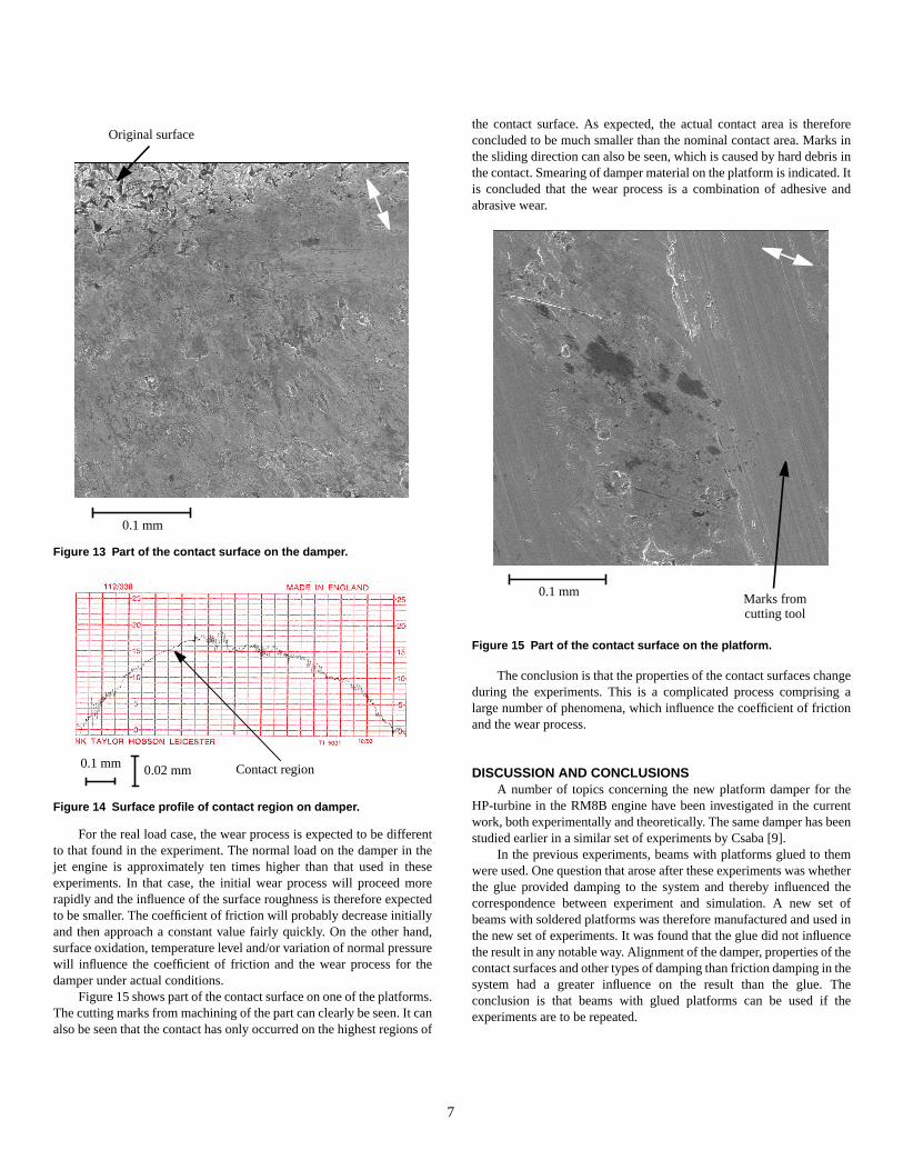
Electron Microscope, SEM. A number of pictures were taken of thecontact surfaces. Figure 13 shows the contact surface on one of thedampers and Fig. 15 the contact surface on one of the platforms. Thesliding direction is marked with a white arrow in both figures.
Figure 13 shows that the contact surface on the damper is smoothedcompared to the original surface structure. This is due to wear of thecontact surface, which reduces the surface roughness. An example of thesurface profile of one contact region of the damper is shown in Fig. 14.It can clearly be seen where the contact has occurred and that the surfaceis smoothed. The inclination of the contact region is about 14˚ and thelength of the contact zone is about 0.25 mm.
The smoothing of the contact surface will most probably reduce thecoefficient of friction and thereby influence the dynamic behaviour ofthe system when the damper is in use. A decrease in coefficient offriction influences the system in the same way as a decrease in normalload, under the assumption that the Coulomb friction law is valid.Hence, the resonance frequency is shifted to a lower frequency and theresonance amplitude increases when the damper is worn. This is the casewhen macroslip is dominant. For the current damper, this phenomenonis found when a new and a used damper are compared, see Fig. 5. Theconclusion is that this behaviour is caused by a decrease in coefficient offriction due to smoothing of the contact surfaces.
Figure 12 Sweeping forward or backward in frequency.
500 550 600 650 700 750 800 8500
0.05
0.1
0.15
0.2
0.25
0.3
Rec
epta
nce,
x/F
[µm
/N]
Frequency [Hz]
Response of blade with shaker attached.
Backward N=100 F=5Forward N=100 F=5
For the real load case, the wear process is expected to be differentto that found in the experiment. The normal load on the damper in thejet engine is approximately ten times higher than that used in theseexperiments. In that case, the initial wear process will proceed morerapidly and the influence of the surface roughness is therefore expectedto be smaller. The coefficient of friction will probably decrease initiallyand then approach a constant value fairly quickly. On the other hand,surface oxidation, temperature level and/or variation of normal pressurewill influence the coefficient of friction and the wear process for thedamper under actual conditions.
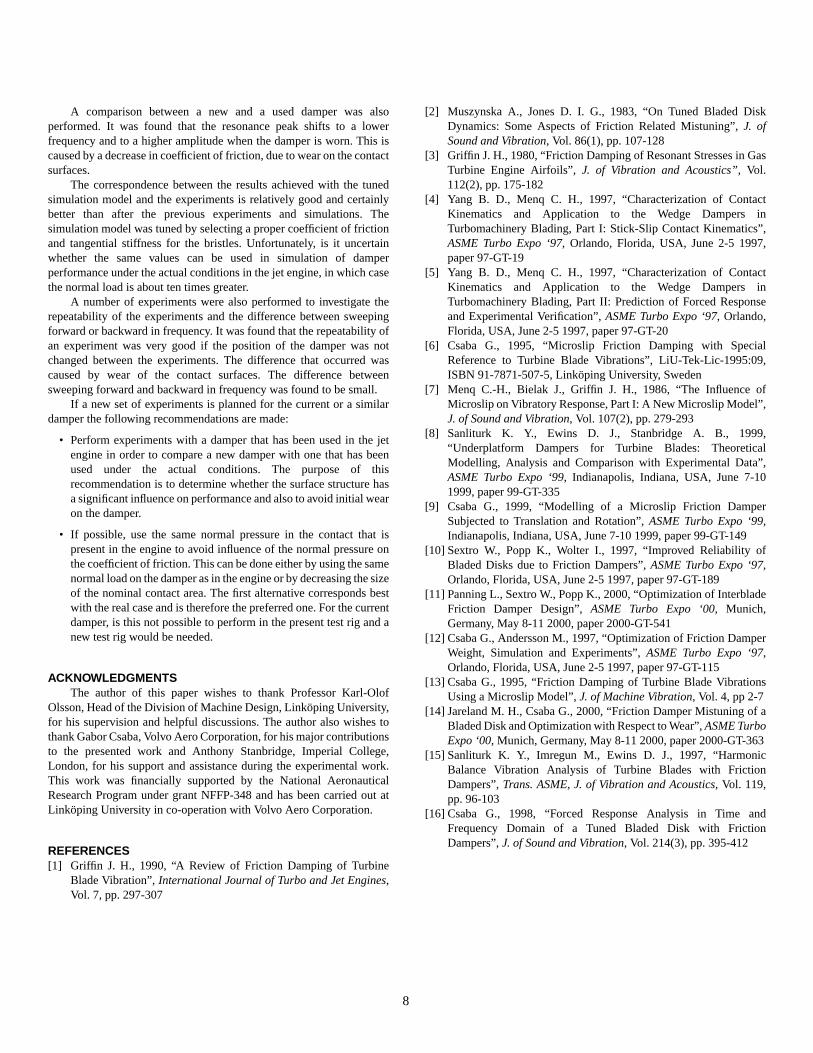
Figure 15 shows part of the contact surface on one of the platforms.The cutting marks from machining of the part can clearly be seen. It canalso be seen that the contact has only occurred on the highest regions of
Figure 13 Part of the contact surface on the damper.
Figure 14 Surface profile of contact region on damper.
0.1 mm
Original surface
0.1 mm 0.02 mm Contact region
7
the contact surface. As expected, the actual contact area is thereforeconcluded to be much smaller than the nominal contact area. Marks inthe sliding direction can also be seen, which is caused by hard debris inthe contact. Smearing of damper material on the platform is indicated. Itis concluded that the wear process is a combination of adhesive andabrasive wear.
The conclusion is that the properties of the contact surfaces changeduring the experiments. This is a complicated process comprising alarge number of phenomena, which influence the coefficient of frictionand the wear process.
DISCUSSION AND CONCLUSIONSA number of topics concerning the new platform damper for the
HP-turbine in the RM8B engine have been investigated in the currentwork, both experimentally and theoretically. The same damper has beenstudied earlier in a similar set of experiments by Csaba [9].
In the previous experiments, beams with platforms glued to themwere used. One question that arose after these experiments was whetherthe glue provided damping to the system and thereby influenced thecorrespondence between experiment and simulation. A new set ofbeams with soldered platforms was therefore manufactured and used inthe new set of experiments. It was found that the glue did not influencethe result in any notable way. Alignment of the damper, properties of thecontact surfaces and other types of damping than friction damping in thesystem had a greater influence on the result than the glue. Theconclusion is that beams with glued platforms can be used if theexperiments are to be repeated.
Figure 15 Part of the contact surface on the platform.
0.1 mm Marks fromcutting tool
A comparison between a new and a used damper was alsoperformed. It was found that the resonance peak shifts to a lowerfrequency and to a higher amplitude when the damper is worn. This iscaused by a decrease in coefficient of friction, due to wear on the contactsurfaces.
The correspondence between the results achieved with the tunedsimulation model and the experiments is relatively good and certainlybetter than after the previous experiments and simulations. Thesimulation model was tuned by selecting a proper coefficient of frictionand tangential stiffness for the bristles. Unfortunately, is it uncertainwhether the same values can be used in simulation of damperperformance under the actual conditions in the jet engine, in which casethe normal load is about ten times greater.
A number of experiments were also performed to investigate therepeatability of the experiments and the difference between sweepingforward or backward in frequency. It was found that the repeatability ofan experiment was very good if the position of the damper was notchanged between the experiments. The difference that occurred wascaused by wear of the contact surfaces. The difference betweensweeping forward and backward in frequency was found to be small.
If a new set of experiments is planned for the current or a similardamper the following recommendations are made:
• Perform experiments with a damper that has been used in the jetengine in order to compare a new damper with one that has beenused under the actual conditions. The purpose of thisrecommendation is to determine whether the surface structure hasa significant influence on performance and also to avoid initial wearon the damper.
• If possible, use the same normal pressure in the contact that ispresent in the engine to avoid influence of the normal pressure onthe coefficient of friction. This can be done either by using the samenormal load on the damper as in the engine or by decreasing the sizeof the nominal contact area. The first alternative corresponds bestwith the real case and is therefore the preferred one. For the currentdamper, is this not possible to perform in the present test rig and anew test rig would be needed.
ACKNOWLEDGMENTSThe author of this paper wishes to thank Professor Karl-Olof
Olsson, Head of the Division of Machine Design, Linköping University,for his supervision and helpful discussions. The author also wishes tothank Gabor Csaba, Volvo Aero Corporation, for his major contributionsto the presented work and Anthony Stanbridge, Imperial College,London, for his support and assistance during the experimental work.This work was financially supported by the National AeronauticalResearch Program under grant NFFP-348 and has been carried out atLinköping University in co-operation with Volvo Aero Corporation.
REFERENCES[1] Griffin J. H., 1990, “A Review of Friction Damping of Turbine
Blade Vibration”, International Journal of Turbo and Jet Engines,Vol. 7, pp. 297-307
8
[2] Muszynska A., Jones D. I. G., 1983, “On Tuned Bladed DiskDynamics: Some Aspects of Friction Related Mistuning”, J. ofSound and Vibration, Vol. 86(1), pp. 107-128
[3] Griffin J. H., 1980, “Friction Damping of Resonant Stresses in GasTurbine Engine Airfoils”, J. of Vibration and Acoustics”, Vol.112(2), pp. 175-182
[4] Yang B. D., Menq C. H., 1997, “Characterization of ContactKinematics and Application to the Wedge Dampers inTurbomachinery Blading, Part I: Stick-Slip Contact Kinematics”,ASME Turbo Expo ‘97, Orlando, Florida, USA, June 2-5 1997,paper 97-GT-19
[5] Yang B. D., Menq C. H., 1997, “Characterization of ContactKinematics and Application to the Wedge Dampers inTurbomachinery Blading, Part II: Prediction of Forced Responseand Experimental Verification”, ASME Turbo Expo ‘97, Orlando,Florida, USA, June 2-5 1997, paper 97-GT-20
[6] Csaba G., 1995, “Microslip Friction Damping with SpecialReference to Turbine Blade Vibrations”, LiU-Tek-Lic-1995:09,ISBN 91-7871-507-5, Linköping University, Sweden
[7] Menq C.-H., Bielak J., Griffin J. H., 1986, “The Influence ofMicroslip on Vibratory Response, Part I: A New Microslip Model”,J. of Sound and Vibration, Vol. 107(2), pp. 279-293
[8] Sanliturk K. Y., Ewins D. J., Stanbridge A. B., 1999,“Underplatform Dampers for Turbine Blades: TheoreticalModelling, Analysis and Comparison with Experimental Data”,ASME Turbo Expo ‘99, Indianapolis, Indiana, USA, June 7-101999, paper 99-GT-335
[9] Csaba G., 1999, “Modelling of a Microslip Friction DamperSubjected to Translation and Rotation”, ASME Turbo Expo ‘99,Indianapolis, Indiana, USA, June 7-10 1999, paper 99-GT-149
[10] Sextro W., Popp K., Wolter I., 1997, “Improved Reliability ofBladed Disks due to Friction Dampers”, ASME Turbo Expo ‘97,Orlando, Florida, USA, June 2-5 1997, paper 97-GT-189
[11] Panning L., Sextro W., Popp K., 2000, “Optimization of InterbladeFriction Damper Design”, ASME Turbo Expo ‘00, Munich,Germany, May 8-11 2000, paper 2000-GT-541
[12] Csaba G., Andersson M., 1997, “Optimization of Friction DamperWeight, Simulation and Experiments”, ASME Turbo Expo ‘97,Orlando, Florida, USA, June 2-5 1997, paper 97-GT-115
[13] Csaba G., 1995, “Friction Damping of Turbine Blade VibrationsUsing a Microslip Model”, J. of Machine Vibration, Vol. 4, pp 2-7
[14] Jareland M. H., Csaba G., 2000, “Friction Damper Mistuning of aBladed Disk and Optimization with Respect to Wear”, ASME TurboExpo ‘00, Munich, Germany, May 8-11 2000, paper 2000-GT-363
[15] Sanliturk K. Y., Imregun M., Ewins D. J., 1997, “HarmonicBalance Vibration Analysis of Turbine Blades with FrictionDampers”, Trans. ASME, J. of Vibration and Acoustics, Vol. 119,pp. 96-103
[16] Csaba G., 1998, “Forced Response Analysis in Time andFrequency Domain of a Tuned Bladed Disk with FrictionDampers”, J. of Sound and Vibration, Vol. 214(3), pp. 395-412