Embed Size (px)
Citation preview
ClonePixTM FL Software Applications Manual Software Release: 1.2.13.971
07MAN1053.A2 Effective Date: 01-Jul-10

GENETIX > CLONEPIX FL SOFTWARE APPLICATION MANUAL
2 of 81
Contents
Overview.............................................................................................................5
Workflows...........................................................................................................6
Pick Run .....................................................................................................................................6
Batch Pick Run ..........................................................................................................................7
Imaging Run ...............................................................................................................................8
Start up ...............................................................................................................9
Main Screen................................................................................................................................9
Processes.................................................................................................................................10
New Process tab ................................................................................................................. 10
Templates tab...................................................................................................................... 10
Recent Processes tab ......................................................................................................... 10
ClonePix FL Processes ...................................................................................11
Prepare for Pick Run ...............................................................................................................11
Pin Fire Test ........................................................................................................................ 11
Alignment............................................................................................................................. 12
Check Wash Bath................................................................................................................ 14
Sanitize Pins in Sterilizing Agent......................................................................................... 15
Ultra Violet Sanitize ............................................................................................................. 15
Check Bottles ...................................................................................................................... 16
Sanitize Pins........................................................................................................................ 16
Finish ................................................................................................................................... 17
Pick Run ...................................................................................................................................18
Modify Settings .................................................................................................................... 19
Start Picking ........................................................................................................................ 24
Imaging Run .............................................................................................................................40
Modify Settings .................................................................................................................... 41
Start Imaging ....................................................................................................................... 42
Maintenance Processes ..................................................................................45
Commissioning Process.........................................................................................................45
Set Drive Limits ................................................................................................................... 45
Image Resolution ................................................................................................................ 45
Drive Resolution .................................................................................................................. 47
Drive Alignment ................................................................................................................... 47
Datum Instrument ................................................................................................................ 47
GENETIX > CLONEPIX FL SOFTWARE APPLICATION MANUAL
3 of 81
Pin Offsets ........................................................................................................................... 52
Utility Processes ..............................................................................................53
Picking Head Management .....................................................................................................53
Remove Head...................................................................................................................... 53
Replace Head...................................................................................................................... 53
Convert QSoft ClonePix FL Images.......................................................................................55
Image Locations .................................................................................................................. 55
Source ................................................................................................................................. 55
Annotations.......................................................................................................................... 56
Utility Process..........................................................................................................................57
Plate Handling ..................................................................................................................... 57
Sanitize Pins........................................................................................................................ 57
UV Sanitize.......................................................................................................................... 57
Replacement Parts and Optional Extras........................................................58
Replacement Parts ..................................................................................................................58
Optional Extras ........................................................................................................................58
Reagents and Supplies....................................................................................59
CloneDetect Detection Reagents ...........................................................................................59
CloneMatrix ..............................................................................................................................60
CloneMedia / XPMedia ............................................................................................................60
PetriWell Cell Culture Plates ..................................................................................................61
Other .........................................................................................................................................62
Appendix A: Imaging Definitions....................................................................63
Statistics for Prime Configurations .......................................................................................63
Appendix B: Imaging Definitions....................................................................65
Statistics for Fluorophore Configurations............................................................................65
Appendix C: Guide to Fluorophore Configurations......................................66
Measuring Fluorescence ........................................................................................................66
Example of Fluorescent Statistic Generation.......................................................................67
Interior Intensity Statistics .....................................................................................................67
Exterior Intensity Statistics Calculation................................................................................68
Exterior Intensity Statistics ....................................................................................................69
Appendix D: Licensing ....................................................................................71
Requesting a license...............................................................................................................71
Installing a license...................................................................................................................73
Appendix E: Reviewing and Exporting Data..................................................75

GENETIX > CLONEPIX FL SOFTWARE APPLICATION MANUAL
4 of 81
Review Results ........................................................................................................................75
Remote Data Viewer ................................................................................................................75
Results Report .........................................................................................................................75
Data Tracking Logs .................................................................................................................75
Automatic Logs........................................................................................................................76
Raw Data...................................................................................................................................77
Appendix F: Glossary of Terms......................................................................78
Contact Details.................................................................................................81
GENETIX > CLONEPIX FL SOFTWARE APPLICATION MANUAL
5 of 81
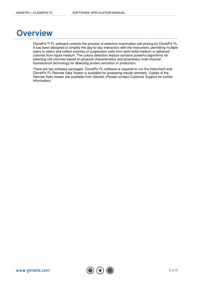
Overview ClonePix™ FL software controls the process of selective mammalian cell picking by ClonePix FL. It has been designed to simplify the day-to-day interaction with the instrument, permitting multiple users to select and collect colonies of suspension cells from semi-solid medium or adherent colonies from liquid medium. The colony detection feature contains powerful algorithms for selecting cell colonies based on physical characteristics and proprietary multi-channel fluorescence technology for detecting protein secretion or production.
There are two software packages. ClonePix FL software is required to run the instrument and ClonePix FL Remote Data Viewer is available for accessing results remotely. Copies of the Remote Data Viewer are available from Genetix (Please contact Customer Support for further information).
GENETIX > CLONEPIX FL SOFTWARE APPLICATION MANUAL
6 of 81
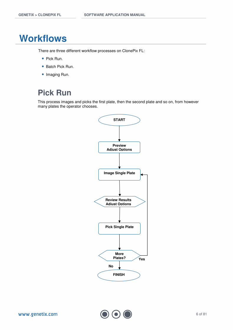
Workflows There are three different workflow processes on ClonePix FL:
• Pick Run.
• Batch Pick Run.
• Imaging Run.
Pick Run This process images and picks the first plate, then the second plate and so on, from however many plates the operator chooses.
START
Preview Adjust Options
Image Single Plate
FINISH
More Plates?
Pick Single Plate
Review Results Adjust Options
Yes
No

GENETIX > CLONEPIX FL SOFTWARE APPLICATION MANUAL
7 of 81
Batch Pick Run This process images all plates in the cassette and aggregates statistics for all plates. The cassette is then manually repositioned and the required clones are picked from the whole batch.
START
Preview Adjust Options
Image All Plates
FINISH
Pick All Plates
Review Results Adjust Options
Reload Plates for Pick

GENETIX > CLONEPIX FL SOFTWARE APPLICATION MANUAL
8 of 81
Imaging Run This process images all plates without picking. Once the plates are imaged, the results can be opened on ClonePix FL or loaded into the Remote Data Viewer (installed on another PC or laptop) and the images re-analyzed with different statistical criteria. This process is used to observe the status of plates during incubation, or to monitor growth and secretion over a period of time.
START
Preview Adjust Options
Image All Plates
FINISH
Review Results Adjust Options

GENETIX > CLONEPIX FL SOFTWARE APPLICATION MANUAL
9 of 81
Start up To start ClonePix FL software, double-click the icon on the Windows desktop.
This will load the robot configuration, initialize the drives and display the main navigation screen.
Main Screen The Main Screen enables navigation of the default processes:
Main Screen
Control of Interior Light: The interior light can be activated or deactivated at any time by double clicking the interior light icon in the bottom right corner of the screen.
The Open Process button can be used to browse for any saved Process or Template.

GENETIX > CLONEPIX FL SOFTWARE APPLICATION MANUAL
10 of 81
Processes A Process is a standard program for ClonePix FL to carry out a task such as a series of similar experiments, or a maintenance task.
New Process tab The New Process tab provides default ClonePix FL processes for use as templates for new imaging or picking processes. It also contains Maintenance and Utility Processes.
Templates tab Saved templates can be retrieved by clicking on this tab.
Recent Processes tab Recent processes can be retrieved by clicking on this tab.
GENETIX > CLONEPIX FL SOFTWARE APPLICATION MANUAL
11 of 81
ClonePix FL Processes
Prepare for Pick Run This process should be carried out prior to a Pick Run to ensure that ClonePix FL is ready for picking. Any section of the following process can be bypassed by clicking Next.
Click Start to begin the Process.
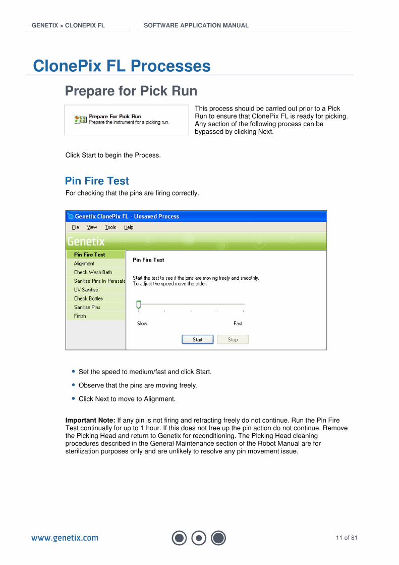
Pin Fire Test For checking that the pins are firing correctly.
• Set the speed to medium/fast and click Start.
• Observe that the pins are moving freely.
• Click Next to move to Alignment.
Important Note: If any pin is not firing and retracting freely do not continue. Run the Pin Fire Test continually for up to 1 hour. If this does not free up the pin action do not continue. Remove the Picking Head and return to Genetix for reconditioning. The Picking Head cleaning procedures described in the General Maintenance section of the Robot Manual are for sterilization purposes only and are unlikely to resolve any pin movement issue.
GENETIX > CLONEPIX FL SOFTWARE APPLICATION MANUAL
12 of 81
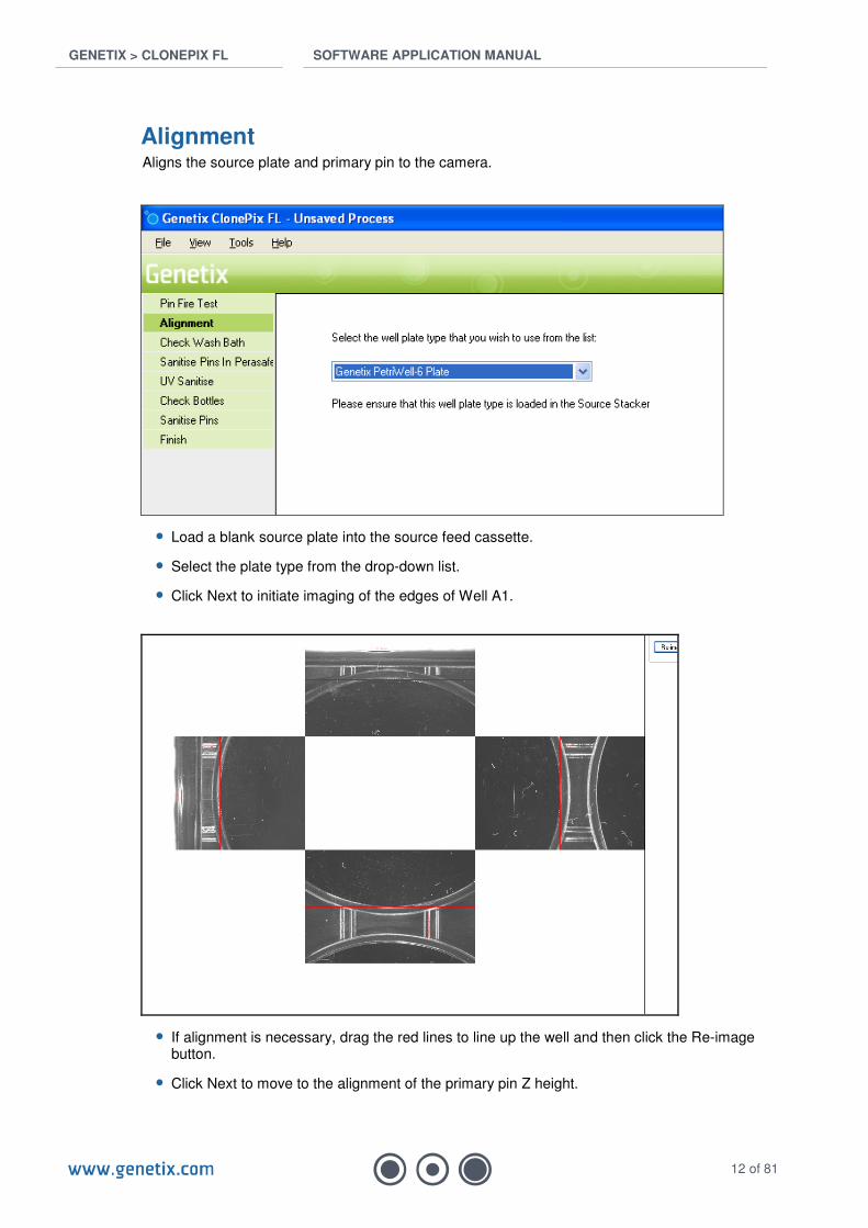
Alignment Aligns the source plate and primary pin to the camera.
• Load a blank source plate into the source feed cassette.
• Select the plate type from the drop-down list.
• Click Next to initiate imaging of the edges of Well A1.
• If alignment is necessary, drag the red lines to line up the well and then click the Re-image button.
• Click Next to move to the alignment of the primary pin Z height.

GENETIX > CLONEPIX FL SOFTWARE APPLICATION MANUAL
13 of 81
Important note: In normal usage the Z height of the primary pin should not require adjustment. Genetix recommends moving to the next stage without modification. If you need to adjust the pin height:
• Set ‘Stop Short Above’ to 5mm then click ‘Goto Source Plate Station’. Note: The datum point can only be set with the pin extended.
• Using the ‘Vertical’ arrow buttons lower the pin until it just touches the bottom of the well. This can be checked by retracting and firing the pin or by use of the Genetix pressure meter for more a more accurate setting.
• When the pin is in the required position click ‘Set’.
• Click Next to move to alignment of the primary pin X & Y coordinates.
GENETIX > CLONEPIX FL SOFTWARE APPLICATION MANUAL
14 of 81
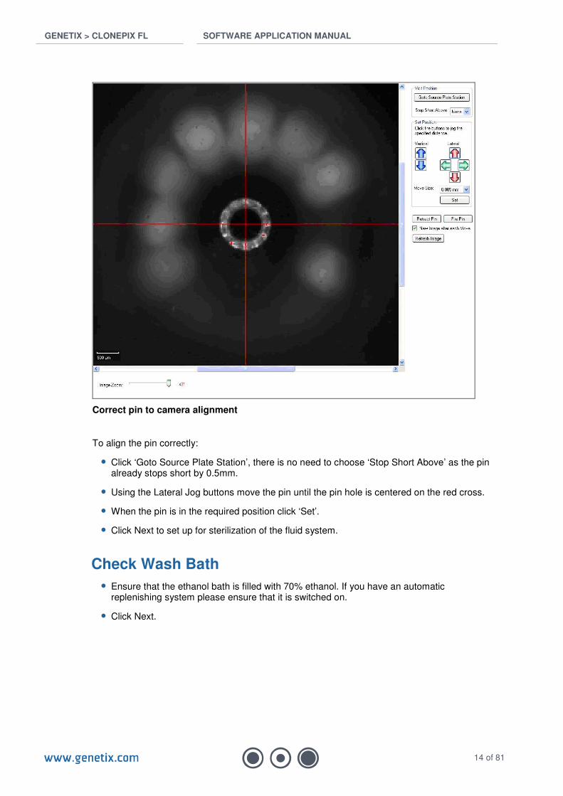
Correct pin to camera alignment
To align the pin correctly:
• Click ‘Goto Source Plate Station’, there is no need to choose ‘Stop Short Above’ as the pin already stops short by 0.5mm.
• Using the Lateral Jog buttons move the pin until the pin hole is centered on the red cross.
• When the pin is in the required position click ‘Set’.
• Click Next to set up for sterilization of the fluid system.
Check Wash Bath
• Ensure that the ethanol bath is filled with 70% ethanol. If you have an automatic replenishing system please ensure that it is switched on.
• Click Next.

GENETIX > CLONEPIX FL SOFTWARE APPLICATION MANUAL
15 of 81
Sanitize Pins in Sterilizing Agent This step sanitizes the pump system between the sterile wash bottle and the picking pins.
• Connect a wash bottle containing freshly prepared Sterilizing Agent (Catalogue Number K8080) to the wash supply line.
• Click Start to pump the Sterilizing Agent through the entire system. This will take several minutes. The Sterilizing Agent needs to be left for 10 minutes - this can be done in parallel with UV sterilization (see next step).
• Click Next.
Ultra Violet Sanitize
This step activates the interior germicidal lamp.
• Set the required duration. Genetix recommends 10 minutes (600 seconds).
• Click Begin. The lamp will switch off after the set time. If the protective door is opened the lamp will switch off until the door is closed.
• Click Next.
GENETIX > CLONEPIX FL SOFTWARE APPLICATION MANUAL
16 of 81
Check Bottles At this point the Sterilizing Agent needs to be purged with sterile water.
• Disconnect the fluid supply line from the bottle containing Sterilizing Agent and connect to an autoclaved bottle of high quality water.
• Empty the waste bottle.
• Click Next to set up Purge conditions.
Note: The connectors seal automatically when disconnected but it is advisable to liberally spray both ends with 70% ethanol before connecting the wash bottle.
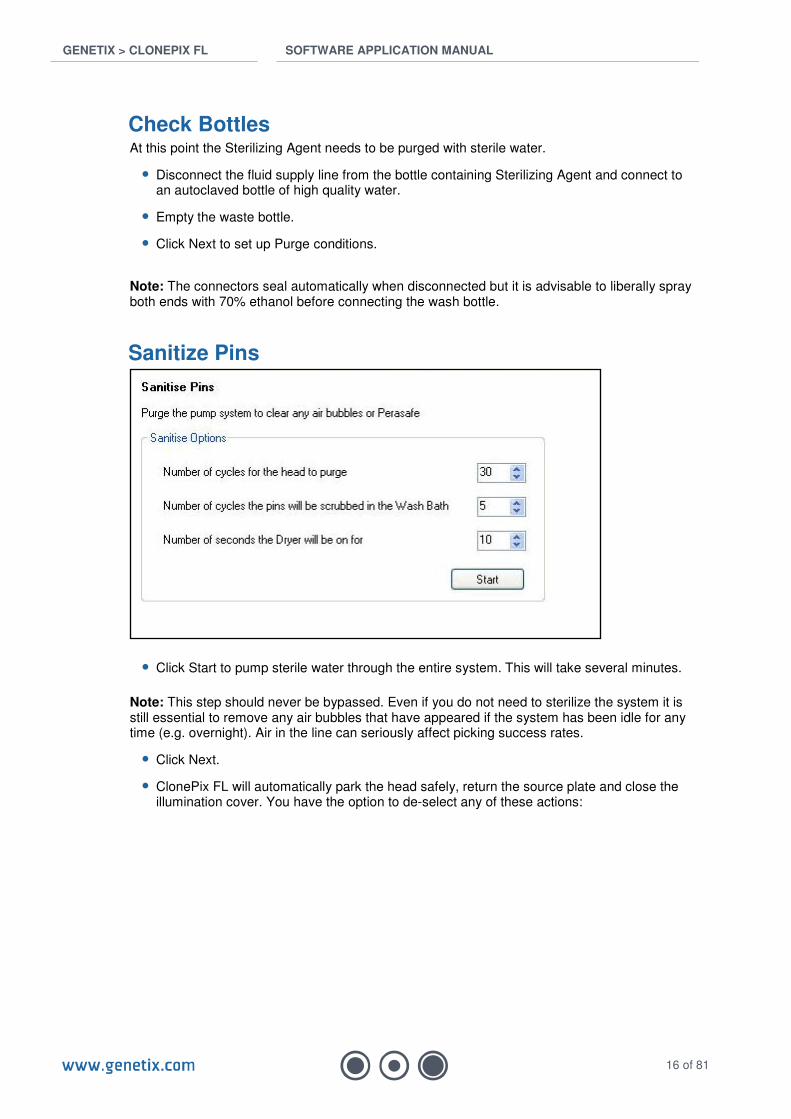
Sanitize Pins
• Click Start to pump sterile water through the entire system. This will take several minutes.
Note: This step should never be bypassed. Even if you do not need to sterilize the system it is still essential to remove any air bubbles that have appeared if the system has been idle for any time (e.g. overnight). Air in the line can seriously affect picking success rates.
• Click Next.
• ClonePix FL will automatically park the head safely, return the source plate and close the illumination cover. You have the option to de-select any of these actions:

GENETIX > CLONEPIX FL SOFTWARE APPLICATION MANUAL
17 of 81
• Click Next.
Finish
• Click Finish to return to the Prepare for Pick Run Process top page.
• Click Close Process to return to the Main Screen.
GENETIX > CLONEPIX FL SOFTWARE APPLICATION MANUAL
18 of 81
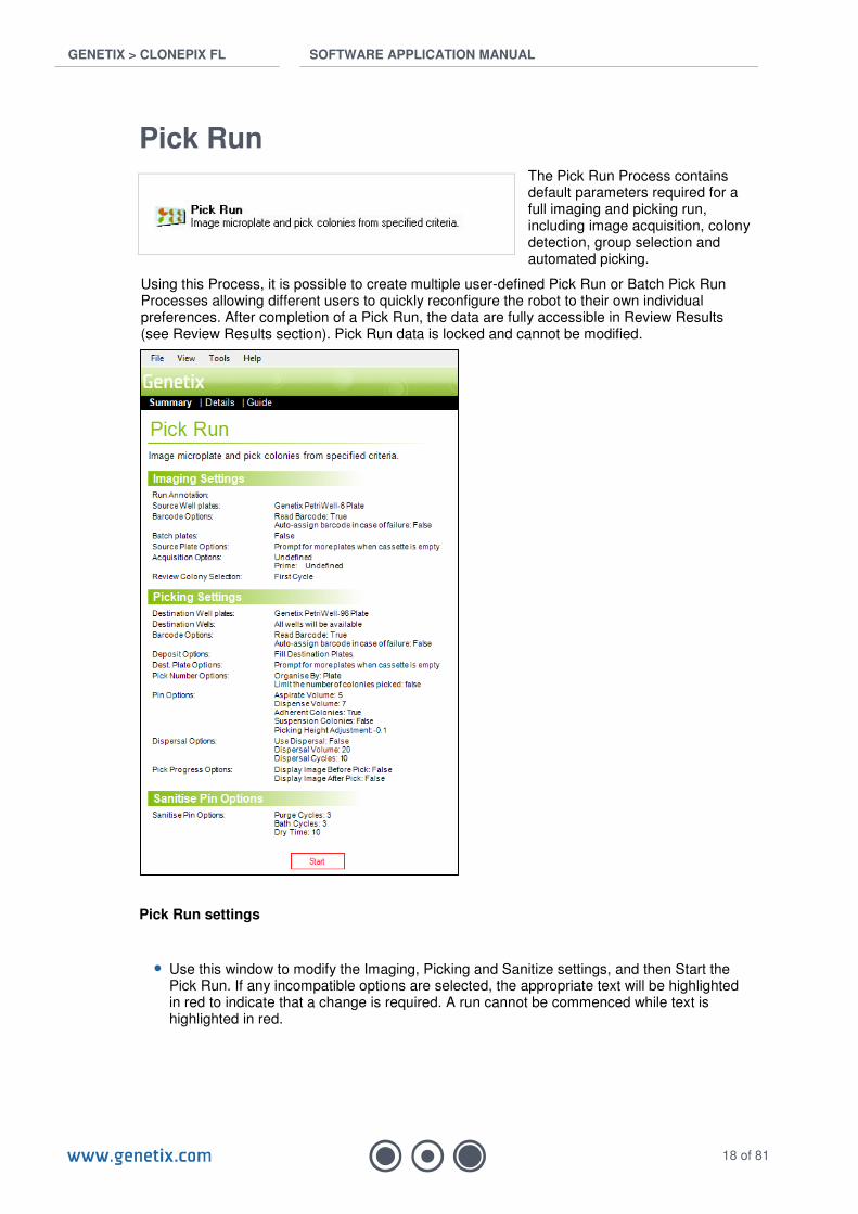
Pick Run The Pick Run Process contains default parameters required for a full imaging and picking run, including image acquisition, colony detection, group selection and automated picking.
Using this Process, it is possible to create multiple user-defined Pick Run or Batch Pick Run Processes allowing different users to quickly reconfigure the robot to their own individual preferences. After completion of a Pick Run, the data are fully accessible in Review Results (see Review Results section). Pick Run data is locked and cannot be modified.
Pick Run settings
• Use this window to modify the Imaging, Picking and Sanitize settings, and then Start the Pick Run. If any incompatible options are selected, the appropriate text will be highlighted in red to indicate that a change is required. A run cannot be commenced while text is highlighted in red.
GENETIX > CLONEPIX FL SOFTWARE APPLICATION MANUAL
19 of 81
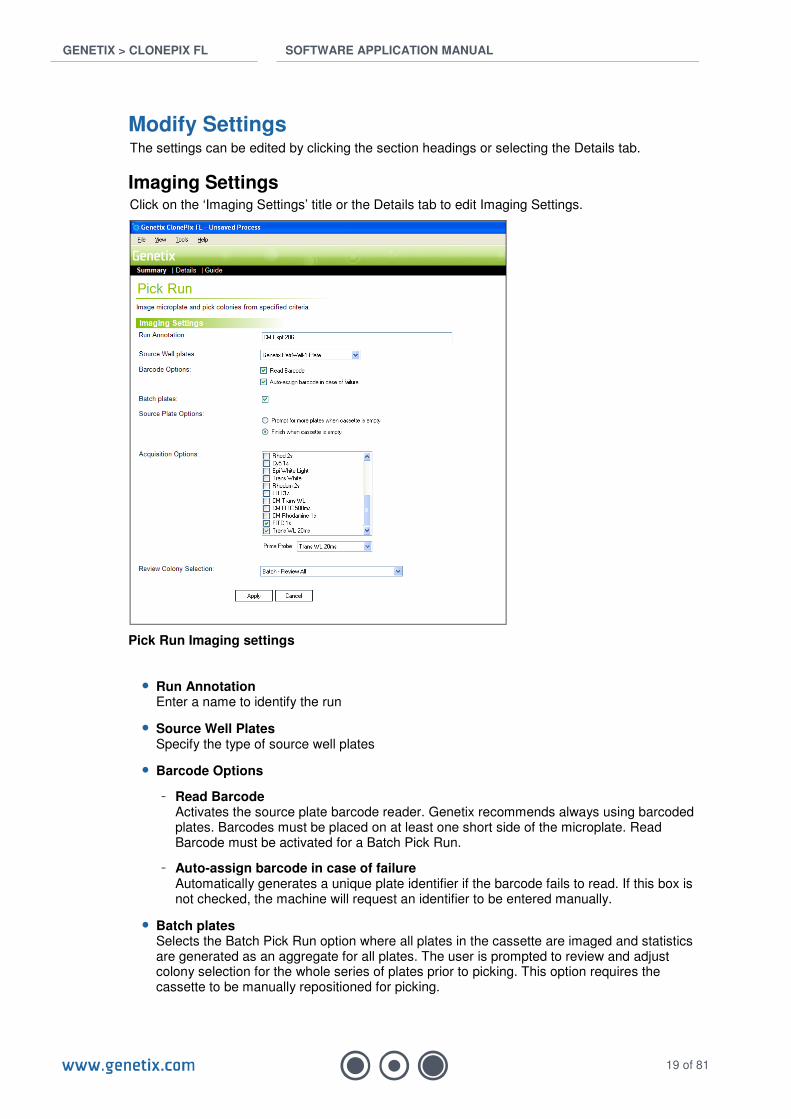
Modify Settings The settings can be edited by clicking the section headings or selecting the Details tab.
Imaging Settings Click on the ‘Imaging Settings’ title or the Details tab to edit Imaging Settings.
Pick Run Imaging settings
• Run Annotation Enter a name to identify the run
• Source Well Plates Specify the type of source well plates
• Barcode Options
- Read Barcode Activates the source plate barcode reader. Genetix recommends always using barcoded plates. Barcodes must be placed on at least one short side of the microplate. Read Barcode must be activated for a Batch Pick Run.
- Auto-assign barcode in case of failure Automatically generates a unique plate identifier if the barcode fails to read. If this box is not checked, the machine will request an identifier to be entered manually.
• Batch plates Selects the Batch Pick Run option where all plates in the cassette are imaged and statistics are generated as an aggregate for all plates. The user is prompted to review and adjust colony selection for the whole series of plates prior to picking. This option requires the cassette to be manually repositioned for picking.
GENETIX > CLONEPIX FL SOFTWARE APPLICATION MANUAL
20 of 81
• Source Plate Options Specify the actions to be taken relating to the source plate supply:
- Prompt for more plates when cassette is empty (not available for a Batch Pick Run)
- Finish when cassette is empty
• Acquisition Options Select Image Acquisition options here, e.g. white light, FITC, etc. The acquisition options can be further modified in Preview (see below).
• Prime Probe The Prime Probe is the image acquisition option to be used for colony detection. Normally, this will be the white light acquisition option, although a fluorescent option specifically designed for colony detection could be used, e.g. viability assay such as LiveDetect.
• Review Colony Selection Select one of the following options for reviewing colony selection after imaging:
- After First Microplate Only This will bring up the Results Screen after the first microplate only to allow you to finely adjust Detection and Groups before committing to picking.
- After Every Microplate This will bring up the Results Screen after each microplate is imaged to allow you to finely adjust Detection and Groups before committing to picking.
- Never This will not bring up the Results Screen at all. Picking will proceed based only on parameters set in Preview (see below).
- Batch – Review All Select this option when using Batch Pick Run. All source plates will be imaged and detected permitting review of colony selection for the whole series of plates prior to picking.
GENETIX > CLONEPIX FL SOFTWARE APPLICATION MANUAL
21 of 81
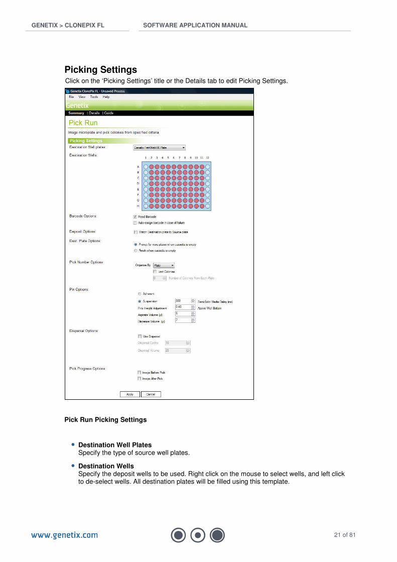
Picking Settings Click on the ‘Picking Settings’ title or the Details tab to edit Picking Settings.
Pick Run Picking Settings
• Destination Well Plates Specify the type of source well plates.
• Destination Wells Specify the deposit wells to be used. Right click on the mouse to select wells, and left click to de-select wells. All destination plates will be filled using this template.
GENETIX > CLONEPIX FL SOFTWARE APPLICATION MANUAL
22 of 81
• Barcode Options
- Read Barcode Activates the destination plate barcode reader. Genetix recommends always using barcoded plates. Barcodes must be placed on at least one short side of the microplate.
- Auto-assign barcode in case of failure Automatically generates a unique plate identifier if the barcode fails to read. If this box is not checked, the machine will request an identifier to be entered manually.
• Deposit Options The default deposit option (box unchecked) sequentially fills all destination plate wells. Checking this box matches destination plate to source plate such that completion of picking from each source plate will prompt the return of the current destination plate.
• Destination Plate Options Specify the actions to be taken relating to the Destination Plate supply:
- Prompt for more plates when cassette is empty
- Finish when cassette is empty
• Pick Number Options ClonePix FL can be set to pick by source plate or by source well. Organize by Plate assumes all wells of the current plate contain the same sample. Organize by Well will pick all specified colonies from well A1 first then proceed to the next well. The latter should be selected when wells of a multi-well source plate contain different samples.
- Limit Colonies. This feature permits the number of colonies picked from each plate or well to be limited.
• Pin Options The following pin options can be set:
- Adherent or Suspension. Select Adherent for collection of colony monolayers and Suspension for collection of colonies from semi-solid medium. By default, there is a 500ms delay for Suspension picking to permit the colonies to be fully collected from semi-solid medium.
- Pick Height Adjustment – The pick height is automatically adjusted for optimal Adherent or Suspension picking (by default these are 0.1mm below and 0.4mm above well bottom, respectively).
- Aspirate volume. Recommended volume is 5µl.
- Dispense volume. Recommended volume is 7µl.
• Dispersal Options Dispersal separates out the cells of a picked colony by aspirating and dispensing in the destination plate. If Dispersal is required the following parameters can be set:
- Dispersal cycles. Recommended is 3-6 for CHO cells and 6-10 for hybridomas. Small colonies in chemically defined media may be best left undispersed.
- Dispersal volume (max 20µl).
• Pick Progress Options
- Image Before Pick – check this box to see each colony immediately prior to being picked.
- Image After Pick – check this box to see that the colony has been successfully collected by the pin.
Note: Activating the Pick Progress Options significantly slows the picking speed and small
GENETIX > CLONEPIX FL SOFTWARE APPLICATION MANUAL
23 of 81
colonies may not be visible. These options can be switched on and off during the run. The images are not saved.
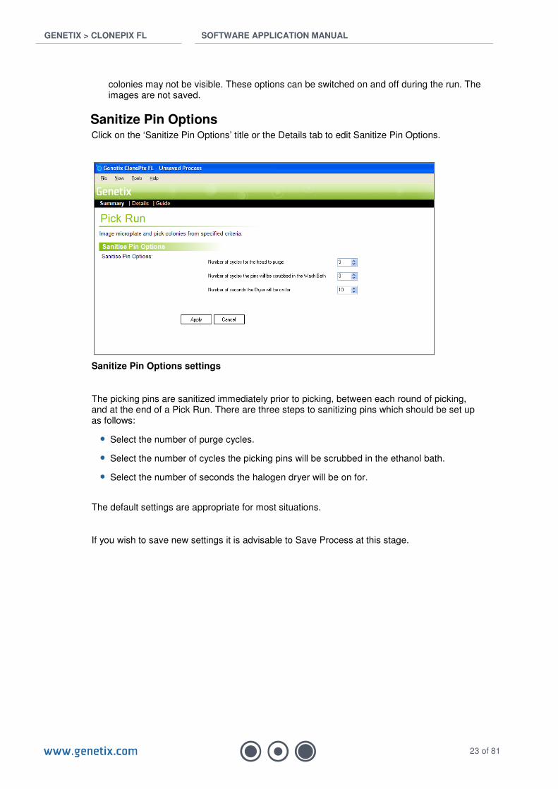
Sanitize Pin Options Click on the ‘Sanitize Pin Options’ title or the Details tab to edit Sanitize Pin Options.
Sanitize Pin Options settings
The picking pins are sanitized immediately prior to picking, between each round of picking, and at the end of a Pick Run. There are three steps to sanitizing pins which should be set up as follows:
• Select the number of purge cycles.
• Select the number of cycles the picking pins will be scrubbed in the ethanol bath.
• Select the number of seconds the halogen dryer will be on for.
The default settings are appropriate for most situations.
If you wish to save new settings it is advisable to Save Process at this stage.

GENETIX > CLONEPIX FL SOFTWARE APPLICATION MANUAL
24 of 81
Start Picking Click on Start to commence the picking process.
Preview The Preview Screen permits the user to establish correct Image Acquisition and Colony Detection settings. A typical screenshot is shown below.
Preview Screen
The screen is divided into two panels: the main panel shows the acquired images, Composite image, Statistics, Scatter Plot and Ranking graphs. These are brought to the front using the tabs at the top of the panel. To the right, a second panel shows the Well Map View, Acquisition Options, Colony Detection Settings, Colony Groups and Colony Information. These are brought to the front using the Settings tabs at the bottom of the panel. The Settings tabs are only visible from the acquired images and Composite image tabs.
In Preview mode, only one image area can be captured and viewed at a time, represented by a purple rectangle in the Well Map. Click an image area on the Well Map to acquire and view all images for that area (as defined in the Acquisition Settings tab).
Settings tabs
Image, Statistics & Graphics tabs
3D View

GENETIX > CLONEPIX FL SOFTWARE APPLICATION MANUAL
25 of 81
Image, Statistics & Graphics tabs
Image tabs
This is where captured images are visualized. If no acquisition configuration options have been selected, no image tabs will be shown:
After image capture, each acquisition option selected will be represented by a tab in the main panel. The composite image tab will also be presented.
This permits different fluorescent combinations to be multiplexed in the same run. Acquired images can be toggled by clicking on the respective tabs.
Palette
Palette button allows the images on-screen to be enhanced or modified.
Export Image
Export Image permits the current image to be exported. The exported image is generated without detection and is shown in the color specified in the acquisition option.
Select / Ruler / Area
Ruler and Area are tools that permit the direct measurement of a colony’s diameter and area, respectively. To measure diameter, select the Ruler icon and then click and drag the mouse across a colony. To measure area, select the Area icon and click on the centre of the colony and drag out to the perimeter. Return to Select after measurement.
Zoom Control
Images can be digitally zoomed using Zoom Control. The magnification is shown to the right of the Image Zoom bar, which turns red when the actual image size is exceeded. Beyond this point the image will become pixelated. The scale bar in the bottom left hand corner of the image pane automatically adjusts with the Zoom Control.

GENETIX > CLONEPIX FL SOFTWARE APPLICATION MANUAL
26 of 81
Composite tab
Fluorescent (non-prime) images can be superimposed onto the prime image in the Composite tab. Required overlay images are selected in the Acquisition tab (see below).
Statistics tab
Displays the statistics for colonies detected in the selected image. Each line represents a detected colony colored according to its Group. Fluorescent image parameters denoted by the prefix [acquisition option] are shown to the left and Prime image parameters are shown to the right. By default, parameters are listed in alphabetical order. Data can be ordered by any parameter by clicking on the chosen header. A second click will inverse the order.
The statistics tab is interactive. A double-click on any row of colony data will hyperlink to the image of the colony (identified with a blue circle). Alternatively, right-clicking on a row will bring up a list of hyperlink options. The right-click menu also allows you to manually assign a colony to a particular Group. Any user-defined modifications to automatic grouping are logged in the statistics column ‘Manual Group’.
• Select Statistics Option to select which properties to display in the statistics table and graphics tabs, or for export. Important: de-selection only hides the data from view, and can be re-selected at any time.

GENETIX > CLONEPIX FL SOFTWARE APPLICATION MANUAL
27 of 81
Select Statistics window
• Export Statistics Opens a wizard for exporting data. Can export statistics for picked colonies only or for all detected colonies. Data can be exported in 1) CSV format for opening as a single sheet in Excel and other statistics software, 2) in Excel-XML for opening in multiple sheets in Excel and other statistics software, or 3) XML format for compatibility with LIMS and other bespoke software. Not functional in Preview.
• Generate Report Opens a wizard for generating an XML-based summary of a Run. The report is generated from information selected in the tabs at the time that the report is generated.

GENETIX > CLONEPIX FL SOFTWARE APPLICATION MANUAL
28 of 81
Scatter Plot tab
Displays scatter plots for colonies detected in the selected image. Use the drop-down lists in the top right-hand corner to compare any two parameters. Fluorescent image parameters denoted by the prefix [acquisition option] are shown at the top of the lists and Prime image parameters are shown at the bottom of the lists.
The Scatter Plot tab is interactive. A double-click on any data point will hyperlink to the image of the colony (identified with a blue circle). Alternatively, right-clicking on a data point will bring up a list of hyperlink options. Right-clicking on the background permits the current graphic image to be copied.
GENETIX > CLONEPIX FL SOFTWARE APPLICATION MANUAL
29 of 81
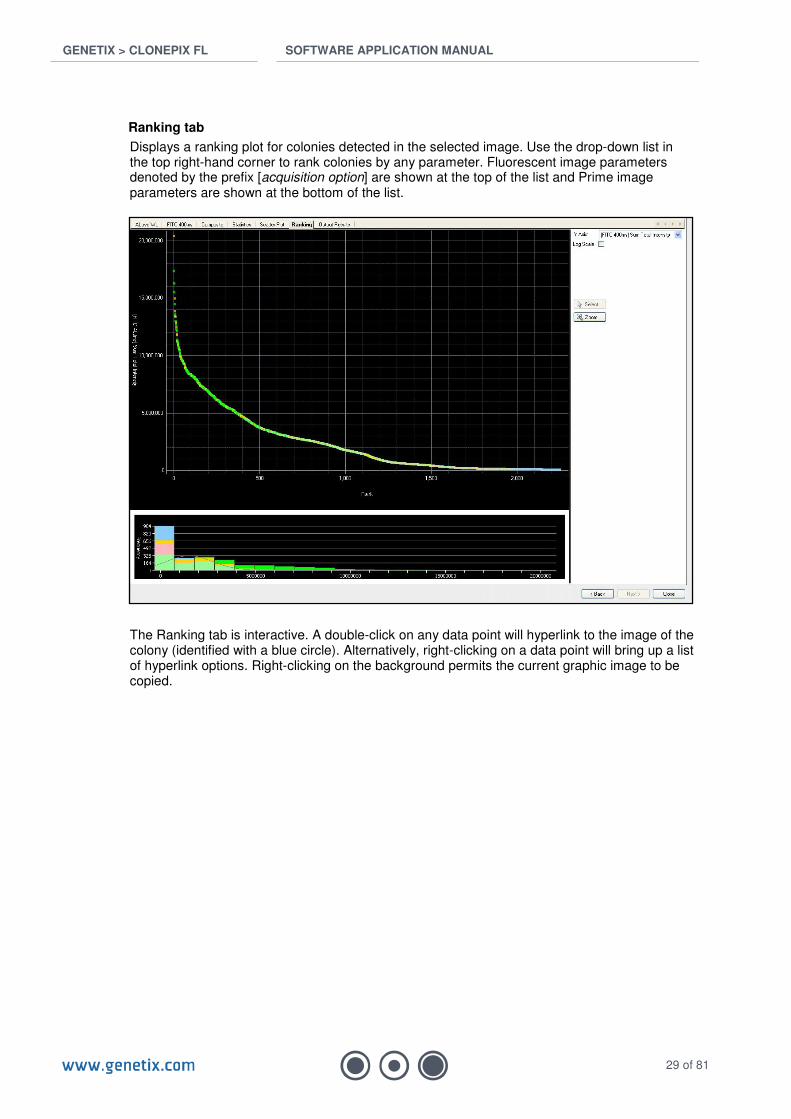
Ranking tab
Displays a ranking plot for colonies detected in the selected image. Use the drop-down list in the top right-hand corner to rank colonies by any parameter. Fluorescent image parameters denoted by the prefix [acquisition option] are shown at the top of the list and Prime image parameters are shown at the bottom of the list.
The Ranking tab is interactive. A double-click on any data point will hyperlink to the image of the colony (identified with a blue circle). Alternatively, right-clicking on a data point will bring up a list of hyperlink options. Right-clicking on the background permits the current graphic image to be copied.
GENETIX > CLONEPIX FL SOFTWARE APPLICATION MANUAL
30 of 81
Settings Tabs
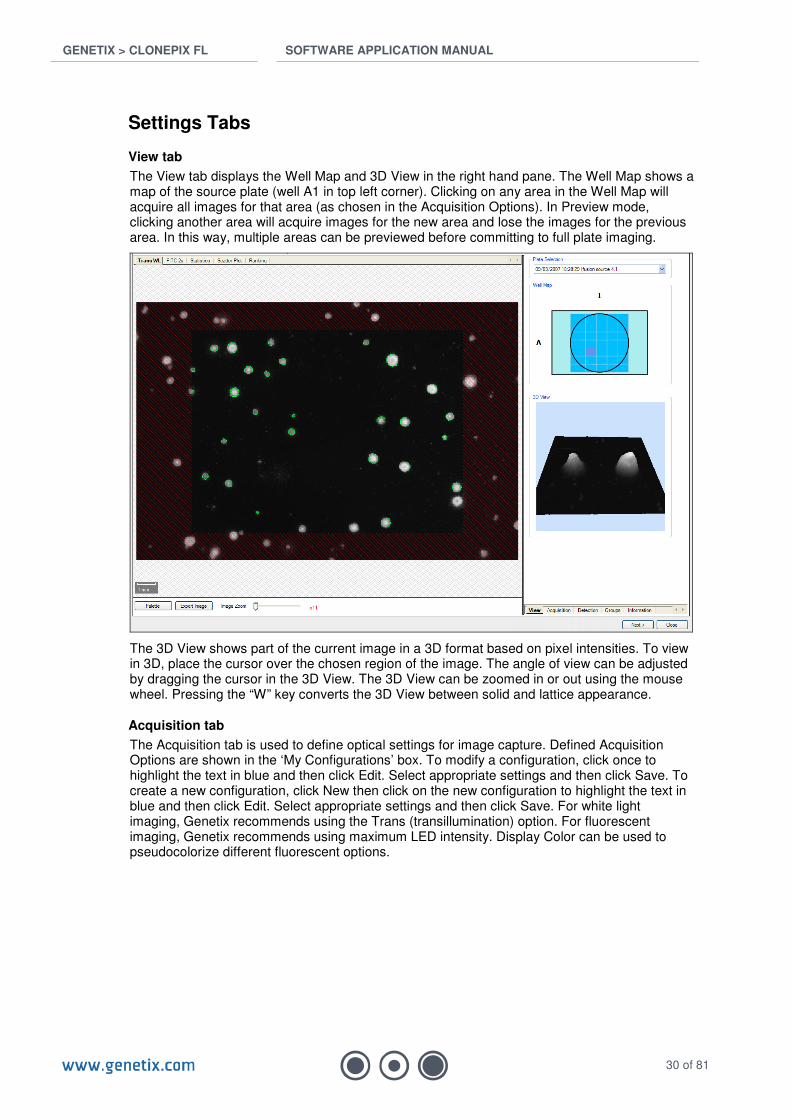
View tab
The View tab displays the Well Map and 3D View in the right hand pane. The Well Map shows a map of the source plate (well A1 in top left corner). Clicking on any area in the Well Map will acquire all images for that area (as chosen in the Acquisition Options). In Preview mode, clicking another area will acquire images for the new area and lose the images for the previous area. In this way, multiple areas can be previewed before committing to full plate imaging.
The 3D View shows part of the current image in a 3D format based on pixel intensities. To view in 3D, place the cursor over the chosen region of the image. The angle of view can be adjusted by dragging the cursor in the 3D View. The 3D View can be zoomed in or out using the mouse wheel. Pressing the “W” key converts the 3D View between solid and lattice appearance.
Acquisition tab
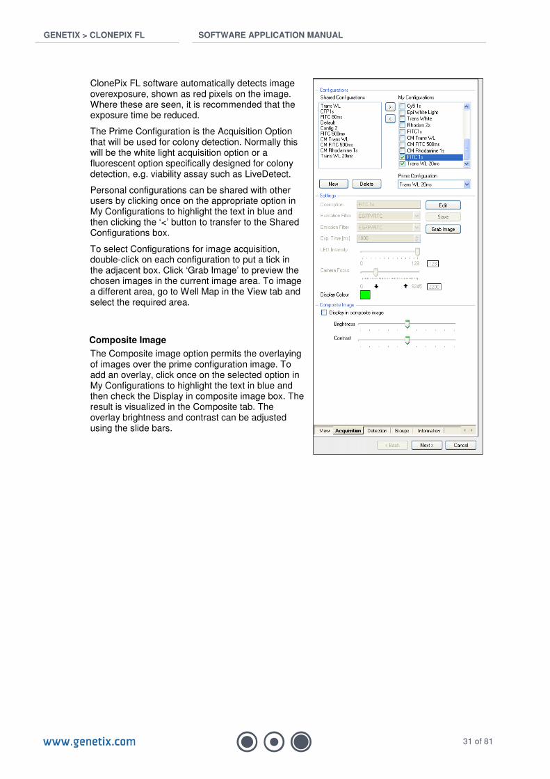
The Acquisition tab is used to define optical settings for image capture. Defined Acquisition Options are shown in the ‘My Configurations’ box. To modify a configuration, click once to highlight the text in blue and then click Edit. Select appropriate settings and then click Save. To create a new configuration, click New then click on the new configuration to highlight the text in blue and then click Edit. Select appropriate settings and then click Save. For white light imaging, Genetix recommends using the Trans (transillumination) option. For fluorescent imaging, Genetix recommends using maximum LED intensity. Display Color can be used to pseudocolorize different fluorescent options.
GENETIX > CLONEPIX FL SOFTWARE APPLICATION MANUAL
31 of 81
ClonePix FL software automatically detects image overexposure, shown as red pixels on the image. Where these are seen, it is recommended that the exposure time be reduced.
The Prime Configuration is the Acquisition Option that will be used for colony detection. Normally this will be the white light acquisition option or a fluorescent option specifically designed for colony detection, e.g. viability assay such as LiveDetect.
Personal configurations can be shared with other users by clicking once on the appropriate option in My Configurations to highlight the text in blue and then clicking the ‘<’ button to transfer to the Shared Configurations box.
To select Configurations for image acquisition, double-click on each configuration to put a tick in the adjacent box. Click ‘Grab Image’ to preview the chosen images in the current image area. To image a different area, go to Well Map in the View tab and select the required area.
Composite Image
The Composite image option permits the overlaying of images over the prime configuration image. To add an overlay, click once on the selected option in My Configurations to highlight the text in blue and then check the Display in composite image box. The result is visualized in the Composite tab. The overlay brightness and contrast can be adjusted using the slide bars.
GENETIX > CLONEPIX FL SOFTWARE APPLICATION MANUAL
32 of 81
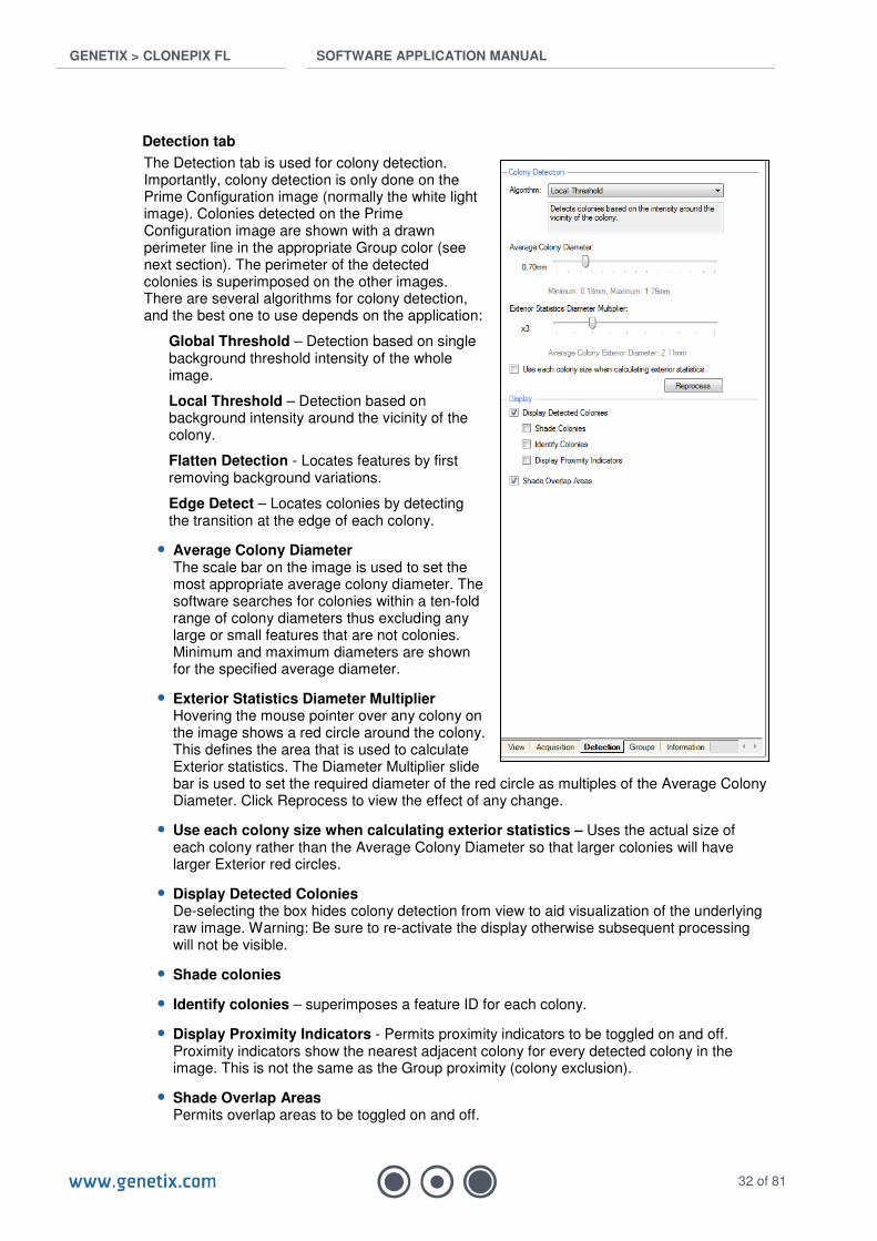
Detection tab
The Detection tab is used for colony detection. Importantly, colony detection is only done on the Prime Configuration image (normally the white light image). Colonies detected on the Prime Configuration image are shown with a drawn perimeter line in the appropriate Group color (see next section). The perimeter of the detected colonies is superimposed on the other images. There are several algorithms for colony detection, and the best one to use depends on the application:
Global Threshold – Detection based on single background threshold intensity of the whole image.
Local Threshold – Detection based on background intensity around the vicinity of the colony.
Flatten Detection - Locates features by first removing background variations.
Edge Detect – Locates colonies by detecting the transition at the edge of each colony.
• Average Colony Diameter The scale bar on the image is used to set the most appropriate average colony diameter. The software searches for colonies within a ten-fold range of colony diameters thus excluding any large or small features that are not colonies. Minimum and maximum diameters are shown for the specified average diameter.
• Exterior Statistics Diameter Multiplier Hovering the mouse pointer over any colony on the image shows a red circle around the colony. This defines the area that is used to calculate Exterior statistics. The Diameter Multiplier slide bar is used to set the required diameter of the red circle as multiples of the Average Colony Diameter. Click Reprocess to view the effect of any change.
• Use each colony size when calculating exterior statistics – Uses the actual size of each colony rather than the Average Colony Diameter so that larger colonies will have larger Exterior red circles.
• Display Detected Colonies De-selecting the box hides colony detection from view to aid visualization of the underlying raw image. Warning: Be sure to re-activate the display otherwise subsequent processing will not be visible.
• Shade colonies
• Identify colonies – superimposes a feature ID for each colony.
• Display Proximity Indicators - Permits proximity indicators to be toggled on and off. Proximity indicators show the nearest adjacent colony for every detected colony in the image. This is not the same as the Group proximity (colony exclusion).
• Shade Overlap Areas Permits overlap areas to be toggled on and off.

GENETIX > CLONEPIX FL SOFTWARE APPLICATION MANUAL
33 of 81
Groups tab
The Groups tab is used to assign detected colonies into groups. These can be set up at the Preview stage but are best done after imaging (see Results, Page 36). The grouping system is designed to generate exclusion groups e.g. Too Small, Irregular, Proximity, and inclusion groups for picking specific populations, e.g. High FITC, High Rhodamine. Multiple groups can be picked in the same picking run but the choice of which groups to pick will be made later (see Select Groups, Page 37). The grouping system works by priority with the group at the top having highest priority. For example, a colony that would fall into two groups will be placed in the highest priority group. Group priority can be changed by using the Increase Priority and Decrease Priority buttons. Any colonies that do not fall into a group are retained in the bottom category. By default, this is called Accept as these are ‘good’ colonies that have not been rejected by morphological characteristics or close neighbor proximity. The bracketed number to the right of the group name indicates the number of colonies in the group. To see the total number of colonies click on ‘All Features’ and look at the data in the ‘Spot Count’ box.
Edge Excluded colonies are outside the pickable region of the well and cannot be selected. This group has highest priority and cannot be moved to a lower priority. Five other exclusion groups are provided by default. You will see these when a new process is initiated, or if you click the ‘Revert to defaults’ button. Each Group has three levels:
a) Group, e.g. Too Small
b) Expression, e.g. IF
c) Rule, e.g. Total area <0.1mm2
To edit a Group, click once on the group name (e.g. Too Small) to highlight it. At the bottom of the pane, the group can be renamed by typing in a new name and clicking Enter. The group can be hidden from view by ticking the Hidden box. This hides them from view on the images and in the Statistics and Graphics tabs. The group color can be changed using the Color button.
To edit a Rule, click on the Rule for the group (e.g. Total area <0.1mm2) which will highlight it.
This brings up a frequency histogram for that property at the bottom of the pane. An inverted triangle indicates the cut-off point and all colonies falling into the group are shaded in the same color as the group. The cut-off value can be shifted by clicking and dragging the bar associated with the inverted triangle, or by writing a new value in the Value box. In the frequency histogram, the colored bars indicate the colonies that are available for selection into the group. The grey bars indicate colonies that have already been placed in higher priority groups. The bottom category (Accept by default) is not a defined group and so does not have a frequency histogram.
With the exception of the Edge Excluded group, any Group, Expression or Rule can be permanently deleted by highlighting it and clicking the Remove button.

GENETIX > CLONEPIX FL SOFTWARE APPLICATION MANUAL
34 of 81
Creating New Groups
Example:
Let’s assume that you want to create a group of FITC-expressing colonies for picking. To do this, you will first need to acquire a white light Prime image and a FITC fluorescent image. Clicking on the New Group button will bring up a new group at the top. Decrease the priority of the group so that it sits just above the Accept category. This means that only colonies with good morphological and proximity characteristics can be put into the group. Re-name the group by highlighting the group name, and typing ‘High FITC’ in the box at the bottom of the pane. Don’t forget to press Enter. Click the Color button and choose an appropriate color. Click on the Rule line for this group (reads ID = “” by default) to bring up a blank histogram box at the bottom of the pane. In the ‘Property’ drop-down list, select [FITC] Sum Total Intensity. In the Operator drop-down list, select ‘>’ (greater than), and then use the vertical slide bar to select a group of high FITC colonies. If required, a second Rule can be created, e.g. low Rhodamine. All colonies in this group are now shown in the Group color in the Image, Statistics and Graphics tabs.
Information tab
Displays information relating to any colony by hovering the mouse pointer over the colony in the image.
• Click Next to proceed.
GENETIX > CLONEPIX FL SOFTWARE APPLICATION MANUAL
35 of 81
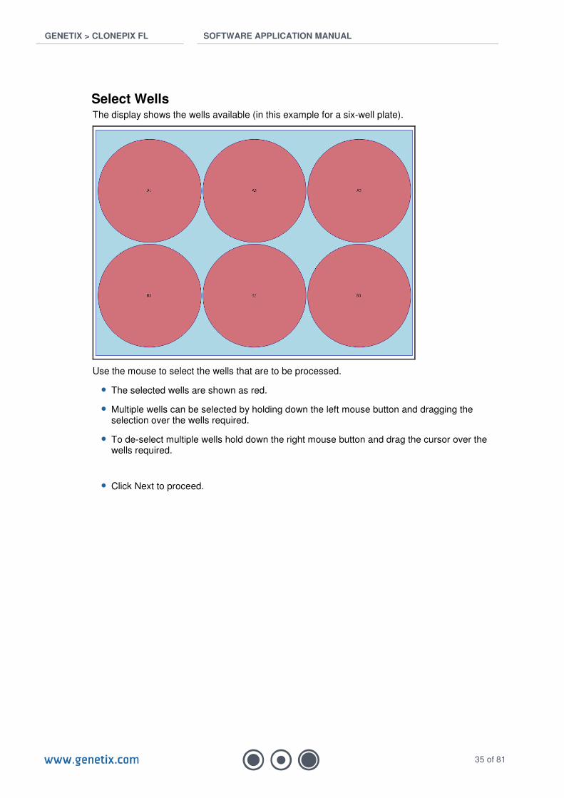
Select Wells The display shows the wells available (in this example for a six-well plate).
Use the mouse to select the wells that are to be processed.
• The selected wells are shown as red.
• Multiple wells can be selected by holding down the left mouse button and dragging the selection over the wells required.
• To de-select multiple wells hold down the right mouse button and drag the cursor over the wells required.
• Click Next to proceed.
GENETIX > CLONEPIX FL SOFTWARE APPLICATION MANUAL
36 of 81
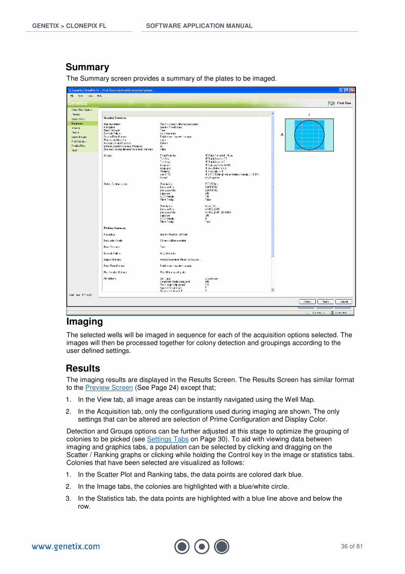
Summary The Summary screen provides a summary of the plates to be imaged.
Imaging
The selected wells will be imaged in sequence for each of the acquisition options selected. The images will then be processed together for colony detection and groupings according to the user defined settings.
Results The imaging results are displayed in the Results Screen. The Results Screen has similar format to the Preview Screen (See Page 24) except that;
1. In the View tab, all image areas can be instantly navigated using the Well Map.
2. In the Acquisition tab, only the configurations used during imaging are shown. The only settings that can be altered are selection of Prime Configuration and Display Color.
Detection and Groups options can be further adjusted at this stage to optimize the grouping of colonies to be picked (see Settings Tabs on Page 30). To aid with viewing data between imaging and graphics tabs, a population can be selected by clicking and dragging on the Scatter / Ranking graphs or clicking while holding the Control key in the image or statistics tabs. Colonies that have been selected are visualized as follows:
1. In the Scatter Plot and Ranking tabs, the data points are colored dark blue.
2. In the Image tabs, the colonies are highlighted with a blue/white circle.
3. In the Statistics tab, the data points are highlighted with a blue line above and below the row.
GENETIX > CLONEPIX FL SOFTWARE APPLICATION MANUAL
37 of 81
Note: The Results Screen is bypassed if ‘Never’ is selected under Review Colony Selection, nor is it shown for subsequent plates if ‘After First Microplate Only’ is selected (see Imaging Settings, Page 19).
• When you are confident that you have grouped the required colonies click Next to proceed.
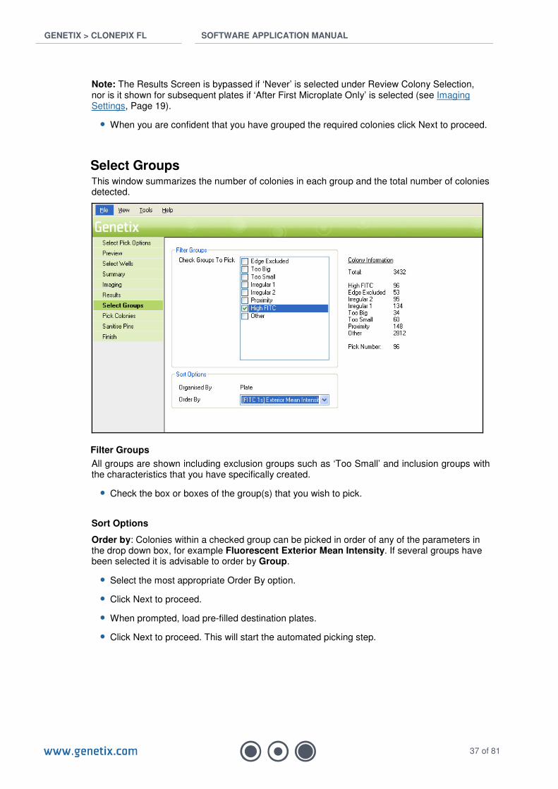
Select Groups This window summarizes the number of colonies in each group and the total number of colonies detected.
Filter Groups
All groups are shown including exclusion groups such as ‘Too Small’ and inclusion groups with the characteristics that you have specifically created.
• Check the box or boxes of the group(s) that you wish to pick.
Sort Options
Order by: Colonies within a checked group can be picked in order of any of the parameters in the drop down box, for example Fluorescent Exterior Mean Intensity. If several groups have been selected it is advisable to order by Group.
• Select the most appropriate Order By option.
• Click Next to proceed.
• When prompted, load pre-filled destination plates.
• Click Next to proceed. This will start the automated picking step.
GENETIX > CLONEPIX FL SOFTWARE APPLICATION MANUAL
38 of 81
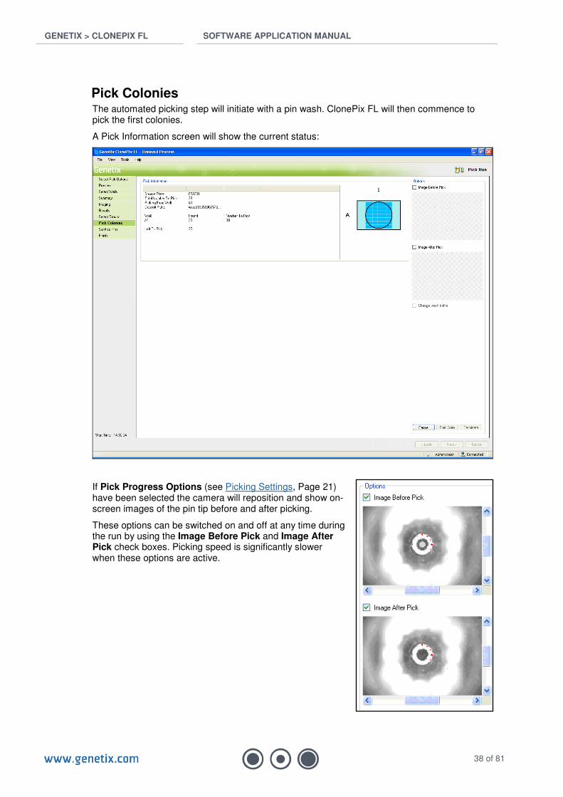
Pick Colonies The automated picking step will initiate with a pin wash. ClonePix FL will then commence to pick the first colonies.
A Pick Information screen will show the current status:
If Pick Progress Options (see Picking Settings, Page 21) have been selected the camera will reposition and show on-screen images of the pin tip before and after picking.
These options can be switched on and off at any time during the run by using the Image Before Pick and Image After Pick check boxes. Picking speed is significantly slower when these options are active.

GENETIX > CLONEPIX FL SOFTWARE APPLICATION MANUAL
39 of 81
• Pause/Continue The run can be paused or continued at any time using this button.
• Park Safe When in Pause mode, the head can be moved to the Park Safe position. Clicking Continue will continue the run from the Park Safe position.
• Terminate When in Pause mode, the run can be terminated immediately. Warning: Be sure that you wish to terminate before clicking this button.
• Change Wash Bottle This function allows the sterile water supply to be replaced during a run. To activate, click Pause, select Change Wash Bottle, and then click Continue. Immediately prior to the next wash cycle, ClonePix FL will prompt you when to swap over the bottle (if this is necessary), and will then commence the long purge. The next cycle of pin washing will revert to the original purge settings. Note: Do not forget to empty the waste bottle each time that the wash bottle is replaced.
Sanitize Pins At the end of each run, the pins are automatically cleaned.
Finish
• Click Finish to return to the Pick Run Process top page.
• Click Close Process to return to the Main Menu. If you have not saved your Process settings, you will be prompted to do so.
To view the results of the picking run, go to Review Results (Page 43).
GENETIX > CLONEPIX FL SOFTWARE APPLICATION MANUAL
40 of 81
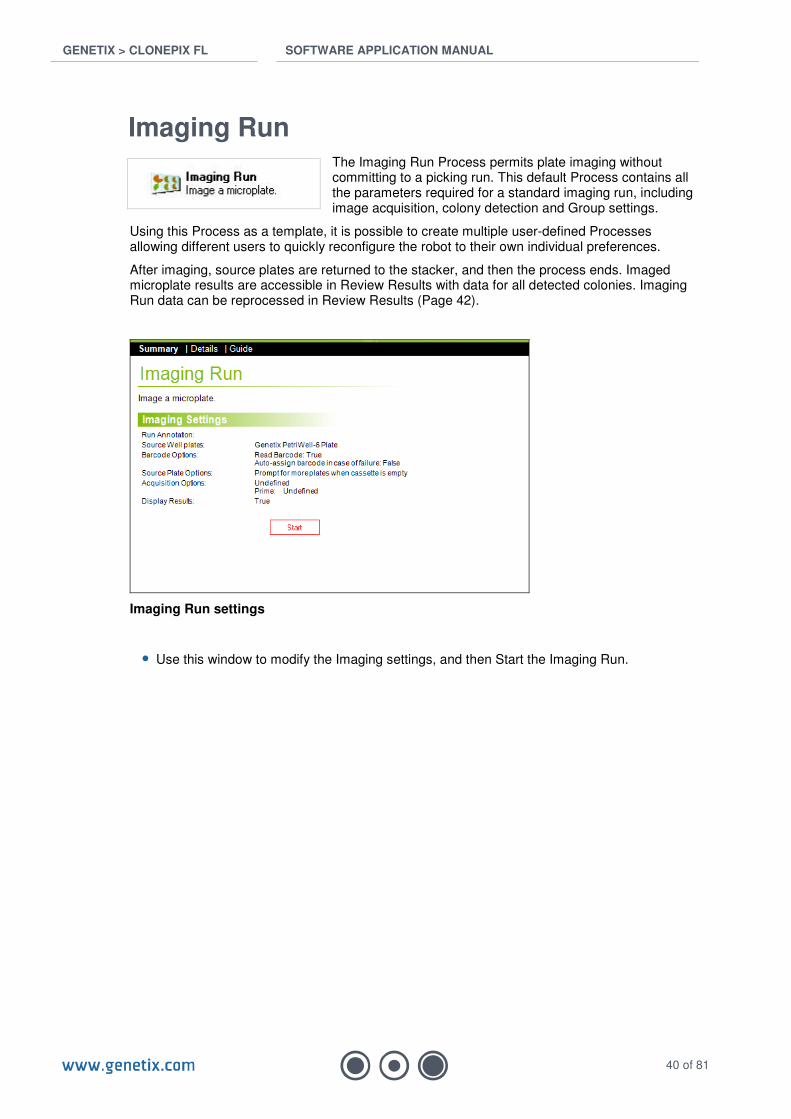
Imaging Run The Imaging Run Process permits plate imaging without committing to a picking run. This default Process contains all the parameters required for a standard imaging run, including image acquisition, colony detection and Group settings.
Using this Process as a template, it is possible to create multiple user-defined Processes allowing different users to quickly reconfigure the robot to their own individual preferences.
After imaging, source plates are returned to the stacker, and then the process ends. Imaged microplate results are accessible in Review Results with data for all detected colonies. Imaging Run data can be reprocessed in Review Results (Page 42).
Imaging Run settings
• Use this window to modify the Imaging settings, and then Start the Imaging Run.
GENETIX > CLONEPIX FL SOFTWARE APPLICATION MANUAL
41 of 81
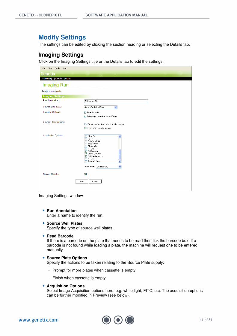
Modify Settings The settings can be edited by clicking the section heading or selecting the Details tab.
Imaging Settings Click on the Imaging Settings title or the Details tab to edit the settings.
Imaging Settings window
• Run Annotation Enter a name to identify the run.
• Source Well Plates Specify the type of source well plates.
• Read Barcode If there is a barcode on the plate that needs to be read then tick the barcode box. If a barcode is not found while loading a plate, the machine will request one to be entered manually.
• Source Plate Options Specify the actions to be taken relating to the Source Plate supply:
- Prompt for more plates when cassette is empty
- Finish when cassette is empty
• Acquisition Options Select Image Acquisition options here, e.g. white light, FITC, etc. The acquisition options can be further modified in Preview (see below).

GENETIX > CLONEPIX FL SOFTWARE APPLICATION MANUAL
42 of 81
• Prime Probe The Prime Probe is the image acquisition option to be used for colony detection. Normally, this will be the white light acquisition option, although a fluorescent option specifically designed for colony detection could be used, e.g. viability assay such as LiveDetect.
• Display Results Click the box to display the results at the end of the run.
If you wish to save new settings it is advisable to Save Process at this stage.
Start Imaging When required settings have been created, click Start.
Preview The Preview Screen permits the user to establish correct Image Acquisition and Colony Detection settings. Please see Preview section under Pick Run for details (Page 24).
Select Wells The Select Wells window permits the user to specify whether to image all wells or just some wells of each plate. Please see Select Wells section under Pick Run for details (Page 35).
Summary The Summary screen provides a summary of the plates to be imaged.
Imaging The selected wells will be imaged in sequence for each of the acquisition options selected and the plate(s) returned. The images will then be processed together for colony detection and groupings according to the user defined settings.
Results If the Display Results option was selected (see Image Settings above), the results will appear after imaging. The Results Screen has similar format to the Preview Screen. All image areas can be instantly navigated using the Well Map on the View tab and collated statistics for the entire plate are now available. Detection and Groups options can be adjusted at this stage (see Settings Tabs, Page 30). If the Display Results option was not selected, the images and results can be accessed via Review Results on the main screen.
Finish
• Click Finish to return to the Imaging Run Process top page.
• Click Close Process to return to the Main Menu. If you have not saved your Process settings, you will be prompted to do so.
To view the results of the imaging run, go to Review Results (next section).

GENETIX > CLONEPIX FL SOFTWARE APPLICATION MANUAL
43 of 81
Review Results
Results of imaging and picking runs are reviewed here. The results can be viewed on ClonePix FL or via the Remote Data Viewer (copies available from Customer Support).
By default, data are stored on the C: drive in a folder called Image Archive. Click Next to open the Image Archive, or if accessing data remotely Browse to Image Archive.
The following window will appear showing a list of completed runs:
Review Results Screen
The results list can be re-arranged by single-clicking on the table headers, or double-clicking to inverse the selection.
• Double click on any row to display that plate in the Review Screen.
• To view multiple plates use Shift-Click or Control-Click to highlight the required rows and then click on View. If you wish to combine the data from multiple plates choose View and process plates as an aggregate when prompted to do so.
The Review Screen has similar format to the Preview Screen except that 1) there is an extra tab (the Output Results tab), and 2) each plate can be viewed via the Plate Selection drop-down list in the top right-hand corner of the Review Screen.
Output Results tab This tab presents the picked colonies and their location in the destination plates. Picked wells are annotated with their Group color and unpicked wells are shown in grey. Destination wells excluded by the user under Picking Settings (Page 21) are shown with a red cross over each well.
The statistics for any colony can be seen in the right hand panel by clicking on a picked well in the 96-well map. A double-click on any picked well will hyperlink to the image of the colony (identified with a blue circle). Right-clicking on any picked well will bring up a list of hyperlink options which let you navigate to the relevant location on the image or in the graphics / statistics tabs.

GENETIX > CLONEPIX FL SOFTWARE APPLICATION MANUAL
44 of 81
Output Results Screen
For detailed explanation of the features within the other tabs refer to the Preview section (Page 24).
Important note: For data integrity Pick Run data are fully accessible in Review Results but the data are locked and thus cannot be modified. Imaging Run data can be altered on-screen but cannot be saved.
• Click Close to exit the run data and return to the Review Results Screen.
Archive results Data stored to Image Archive can be easily copied or transferred to CD or DVD using the Archive result option. To do this, use Shift-Click or Control-Click to highlight the required rows and then click on Archive.
GENETIX > CLONEPIX FL SOFTWARE APPLICATION MANUAL
45 of 81
Maintenance Processes
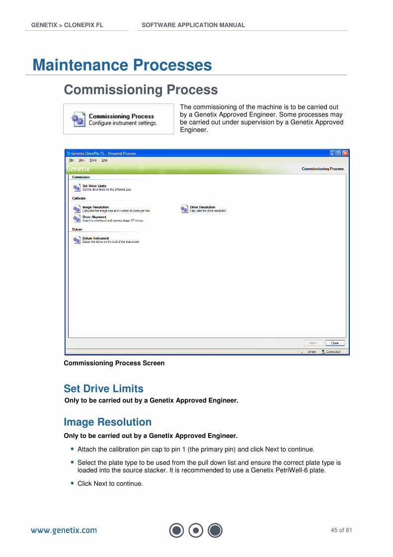
Commissioning Process The commissioning of the machine is to be carried out by a Genetix Approved Engineer. Some processes may be carried out under supervision by a Genetix Approved Engineer.
Commissioning Process Screen
Set Drive Limits Only to be carried out by a Genetix Approved Engineer.
Image Resolution Only to be carried out by a Genetix Approved Engineer.
• Attach the calibration pin cap to pin 1 (the primary pin) and click Next to continue.
• Select the plate type to be used from the pull down list and ensure the correct plate type is loaded into the source stacker. It is recommended to use a Genetix PetriWell-6 plate.
• Click Next to continue.
GENETIX > CLONEPIX FL SOFTWARE APPLICATION MANUAL
46 of 81
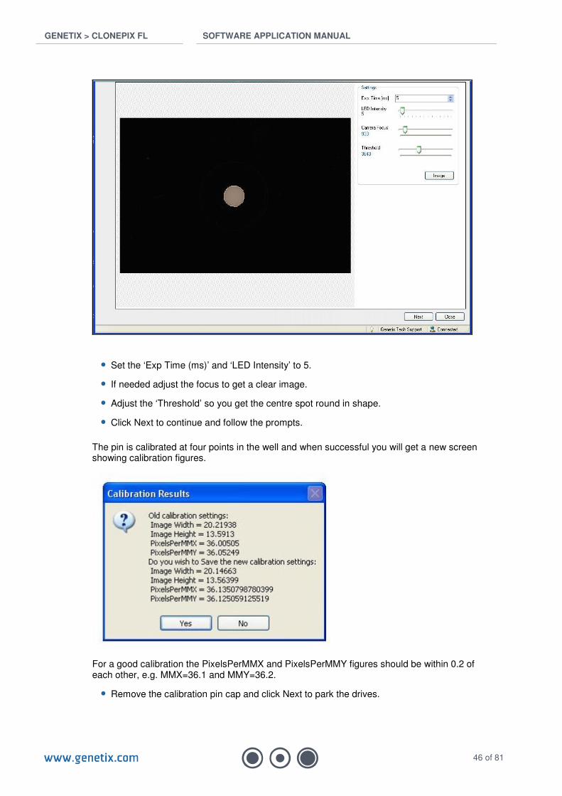
• Set the ‘Exp Time (ms)’ and ‘LED Intensity’ to 5.
• If needed adjust the focus to get a clear image.
• Adjust the ‘Threshold’ so you get the centre spot round in shape.
• Click Next to continue and follow the prompts.
The pin is calibrated at four points in the well and when successful you will get a new screen showing calibration figures.
For a good calibration the PixelsPerMMX and PixelsPerMMY figures should be within 0.2 of each other, e.g. MMX=36.1 and MMY=36.2.
• Remove the calibration pin cap and click Next to park the drives.

GENETIX > CLONEPIX FL SOFTWARE APPLICATION MANUAL
47 of 81
Drive Resolution Only to be carried out by a Genetix Approved Engineer.
Drive Alignment Only to be carried out by a Genetix Approved Engineer.
Datum Instrument Only to be carried out by a Genetix Approved Engineer.
The display shows the list of Datum options together with the date the last datum was carried out.
• Select the datum option required and click Start.
Park Home
• Click Goto ParkSafeWaypoint to move the head to the Park Safe location.
• The picking head should be near or at its home position.
• If required, use the arrows to adjust the position of the Park Safe location.
• The Move Size can be adjusted by selecting the required number from the pull down list.
• When the head is in the required position click Set.
GENETIX > CLONEPIX FL SOFTWARE APPLICATION MANUAL
48 of 81
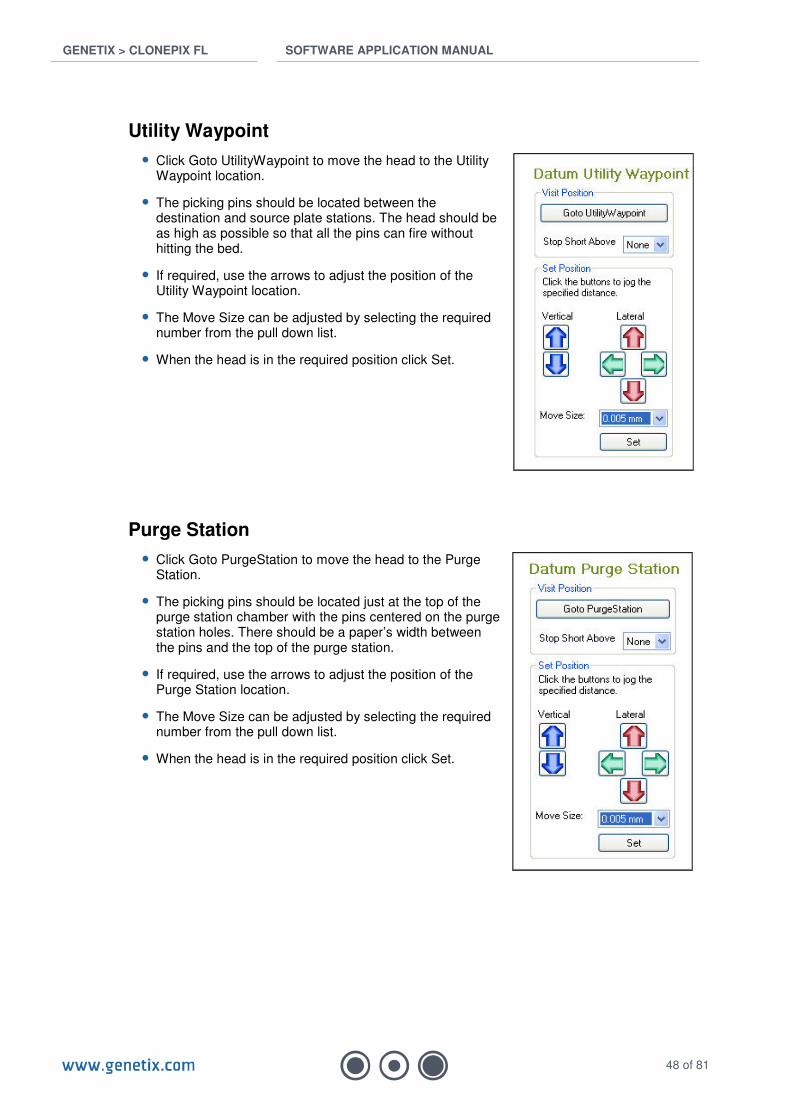
Utility Waypoint
• Click Goto UtilityWaypoint to move the head to the Utility Waypoint location.
• The picking pins should be located between the destination and source plate stations. The head should be as high as possible so that all the pins can fire without hitting the bed.
• If required, use the arrows to adjust the position of the Utility Waypoint location.
• The Move Size can be adjusted by selecting the required number from the pull down list.
• When the head is in the required position click Set.
Purge Station
• Click Goto PurgeStation to move the head to the Purge Station.
• The picking pins should be located just at the top of the purge station chamber with the pins centered on the purge station holes. There should be a paper’s width between the pins and the top of the purge station.
• If required, use the arrows to adjust the position of the Purge Station location.
• The Move Size can be adjusted by selecting the required number from the pull down list.
• When the head is in the required position click Set.

GENETIX > CLONEPIX FL SOFTWARE APPLICATION MANUAL
49 of 81
Wash Station
• Click Goto WashBath to move the head to the Wash Bath (also known as the ethanol bath).
• The picking pins should be located at the top of the wash station chamber with the pins centered in the part of the wash bath that has no bristles. There should be a paper’s width between the pins and the top of the Wash Station.
• If required, use the arrows to adjust the position of the Wash Bath location.
• The Move Size can be adjusted by selecting the required number from the pull down list.
• When the head is in the required position click Set.
Dry Station
• Click Goto DryStation to move the head to the Dry Station.
• The picking pins should be located just at the top of the dry station chamber with the pins centered in the drying area. There should be a paper’s width between the pins and the top of the dry station.
• If required, use the arrows to adjust the position of the pins over the dry station.
• The Move Size can be adjusted by selecting the required number from the pull down list.
• When the head is in the required position click Set.

GENETIX > CLONEPIX FL SOFTWARE APPLICATION MANUAL
50 of 81
Destination Plate
• Select the destination plate type to be used from the drop down list. Make sure that the same plate type is loaded into the destination stacker. It is recommended to use a Genetix PetriWell-96 plate.
• Click Start.
• Click Goto Destination Plate Station to move the head to the Destination Station.
• The picking pins should be located just at the top of the destination plate with the pins centered in the wells. There should be a paper’s width between the pins and the top of the plate.
• If required, use the arrows to adjust the position of the pins over the dry station.
• The Move Size can be adjusted by selecting the required number from the pull down list.
• When the head is in the required position click Set.
Source Plate
• Select the source plate type to be used from the drop down list and ensure the same plate type is loaded into the source stacker. It is recommended to use a Genetix PetriWell-6 plate.
• Click Next to continue.
This process is done in three stages:
Stage 1 – Align camera to well plate
• Drag the red lines until they line up with the plate edge and click Re-image.
• Click Next to continue.
GENETIX > CLONEPIX FL SOFTWARE APPLICATION MANUAL
51 of 81
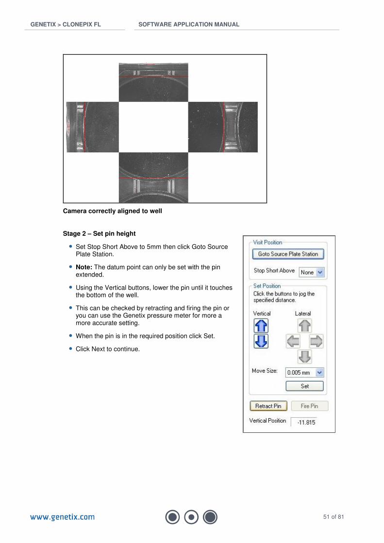
Camera correctly aligned to well
Stage 2 – Set pin height
• Set Stop Short Above to 5mm then click Goto Source Plate Station.
• Note: The datum point can only be set with the pin extended.
• Using the Vertical buttons, lower the pin until it touches the bottom of the well.
• This can be checked by retracting and firing the pin or you can use the Genetix pressure meter for more a more accurate setting.
• When the pin is in the required position click Set.
• Click Next to continue.
GENETIX > CLONEPIX FL SOFTWARE APPLICATION MANUAL
52 of 81
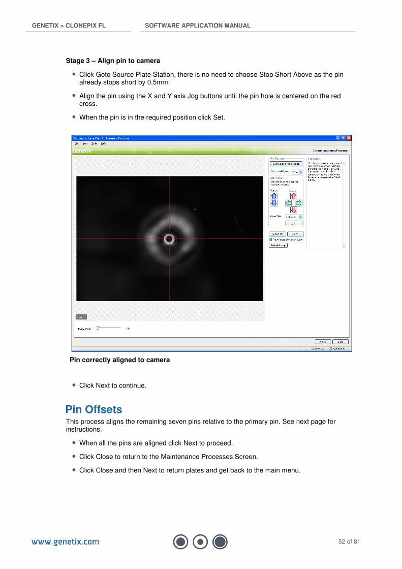
Stage 3 – Align pin to camera
• Click Goto Source Plate Station, there is no need to choose Stop Short Above as the pin already stops short by 0.5mm.
• Align the pin using the X and Y axis Jog buttons until the pin hole is centered on the red cross.
• When the pin is in the required position click Set.
Pin correctly aligned to camera
• Click Next to continue.
Pin Offsets This process aligns the remaining seven pins relative to the primary pin. See next page for instructions.
• When all the pins are aligned click Next to proceed.
• Click Close to return to the Maintenance Processes Screen.
• Click Close and then Next to return plates and get back to the main menu.
GENETIX > CLONEPIX FL SOFTWARE APPLICATION MANUAL
53 of 81
Utility Processes
Picking Head Management Head management options should be used each time the head is removed and/or replaced.
Remove Head Aids removal of the picking head only. If you wish to remove and replace head it may be more convenient to use Replace Head.
• Click on Remove Head icon to bring the head to a convenient location for removal.
• Remove Head by disconnecting silicon supply hoses and locking bolt.
• Click Next to return head to safe location.
Replace Head Process to aid replacement of the picking head followed by preparation of the head for use.
• Click on Replace Head icon to bring the head to a convenient location for replacing.
• Replace Head by connecting locking bolt and silicon supply hoses. It is best to re-connect the hoses starting at the back.
• Click Next to advance to Pin Fire Test (See Page 11).
• Click Next to advance to Alignment to align plate and primary pin (See Page 12).
• Click Next to proceed to Pin Offsets:
Picking Head Pin Offsets This process aligns the remaining seven pins relative to the primary pin. It must be carried out whenever the pins are removed or replaced to compensate for µm differences between pins.
• Select the source plate type to be used from the drop down list and ensure the same plate type is loaded into the source stacker. It is recommended to use a Genetix PetriWell-6 plate.
• Click Start to continue. This will extend the Primary Pin into well A1.
Note: The datum point for the primary pin cannot be set here; it should already have been set in the Alignment procedure above. If the primary pin is misaligned, exit the Replace Head process and start again.
• Click Next Pin. This will extend the next pin into well A1.
• Align the pin using the X and Y axis Jog buttons until the pin hole is centered on the red cross.
• When the pin is in the required position click Set. The new pin coordinates will be shown in red.
• Use the Next Pin button to move through and align/set the remaining pins.

GENETIX > CLONEPIX FL SOFTWARE APPLICATION MANUAL
54 of 81
• Note: If the Previous Pin button is used the pin may appear not to be aligned because the actual position is shown rather than the offset on the assumption that you want to create the offset.
Pin correctly aligned to camera and pins 2 & 3 already aligned shown in red
• Click Next to Sanitize Pins in Sterilizing Agent (See Page 15).
• Click Next to Ultra Violet Sanitize (See Page 15).
• Click Next to Sanitize Pins (purge the system with sterile water) (See Page 16).
• Click Next twice to automatically park the head safely, return the source plate and close the illumination cover.
GENETIX > CLONEPIX FL SOFTWARE APPLICATION MANUAL
55 of 81
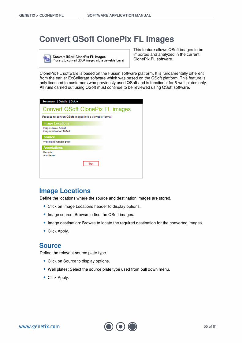
Convert QSoft ClonePix FL Images This feature allows QSoft images to be imported and analyzed in the current ClonePix FL software.
ClonePix FL software is based on the Fusion software platform. It is fundamentally different from the earlier ExCellerate software which was based on the QSoft platform. This feature is only licensed to customers who previously used QSoft and is functional for 6-well plates only. All runs carried out using QSoft must continue to be reviewed using QSoft software.
Image Locations Define the locations where the source and destination images are stored.
• Click on Image Locations header to display options.
• Image source: Browse to find the QSoft images.
• Image destination: Browse to locate the required destination for the converted images.
• Click Apply.
Source Define the relevant source plate type.
• Click on Source to display options.
• Well plates: Select the source plate type used from pull down menu.
• Click Apply.

GENETIX > CLONEPIX FL SOFTWARE APPLICATION MANUAL
56 of 81
Annotations Define annotations for barcode.
• Click on Annotations to display options.
• Enter Barcode and Annotation information.
• Click Apply.
• Click Start to initiate the conversion process.
GENETIX > CLONEPIX FL SOFTWARE APPLICATION MANUAL
57 of 81
Utility Process
The Utility Process provides a number of processes to control or diagnose the hardware.
Utility Processes currently available to the user are:
• Plate Handling.
• Sanitize Pins.
• UV Sanitize.
Plate Handling
Source Plate
• Select Source Plate Station from the Plate Station drop down list.
• Select the type of plate from the Well Plate drop down list.
• Click Get Plate and ensure that the selected plate is collected from the Source Plate Station.
• Click Return Plate and ensure the selected plate is returned to the Source Plate Station.
Destination Plate
• Select Destination Plate Station from the Plate Station drop down list.
• Select the type of plate from the Well Plate drop down list.
• Click Get Plate and ensure that the selected plate is collected from the Destination Plate Station
• Click Return Plate and ensure the selected plate is returned to the Destination Plate Station
Sanitize Pins
• Select the number of purge cycles required.
• Select the number of cycles the picking pins will be scrubbed in the ethanol bath.
• Select the number of seconds the halogen dryer will be on for (recommend 10 seconds).
UV Sanitize
• This feature controls the germicidal lamp inside ClonePix FL as described on Page 15.

GENETIX > CLONEPIX FL SOFTWARE APPLICATION MANUAL
58 of 81
Replacement Parts and Optional Extras Please refer to the Genetix website for the latest replacement parts and optional extras www.genetix.com
Replacement Parts
Code Description
X4941 Additional picking head populated with eight X4961 (F1 Pins)
X4942 Additional picking head populated with eight X4962 (F2 Pins)
X4949 Additional picking head without pins
X4961 F1 – ClonePix FL colony picking pin, 0.40mm diameter (Single pin)
X4962 F2 – ClonePix FL colony picking pin, 0.70mm diameter (Single pin)
X1036 O Rings for picking pins (Pack of 8)
X4970 Replacement picking tubing (Pack of 8)
X4948 Picking Pin Removal Key
X3445D Cassette for stacker system
X4975F 5L Feed (wash) bottle & fixings
X4975W 5L Waste bottle & fixings
X4976 Nylon bristle ethanol bath insert
Optional Extras
Code Description
SL4950-A01 ClonePix FL Remote Data Viewer
X4990 ClonePix FL filter set ex 440 em 505 (CFP)
X4992 ClonePix FL filter set ex 500 em 550 (YFP)
X4993 ClonePix FL filter set ex 530 em 590 (CloneDetect 549, Rhodamine)
X4992 ClonePix FL filter set ex 622 em 700 (CloneDetect 622, Cy5)
GENETIX > CLONEPIX FL SOFTWARE APPLICATION MANUAL
59 of 81
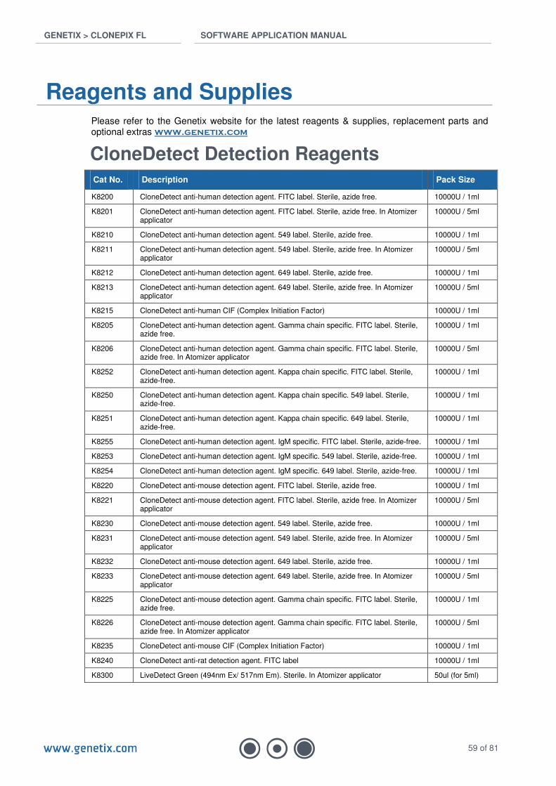
Reagents and Supplies Please refer to the Genetix website for the latest reagents & supplies, replacement parts and optional extras www.genetix.com
CloneDetect Detection Reagents Cat No. Description Pack Size
K8200 CloneDetect anti-human detection agent. FITC label. Sterile, azide free. 10000U / 1ml
K8201 CloneDetect anti-human detection agent. FITC label. Sterile, azide free. In Atomizer applicator
10000U / 5ml
K8210 CloneDetect anti-human detection agent. 549 label. Sterile, azide free. 10000U / 1ml
K8211 CloneDetect anti-human detection agent. 549 label. Sterile, azide free. In Atomizer applicator
10000U / 5ml
K8212 CloneDetect anti-human detection agent. 649 label. Sterile, azide free. 10000U / 1ml
K8213 CloneDetect anti-human detection agent. 649 label. Sterile, azide free. In Atomizer applicator
10000U / 5ml
K8215 CloneDetect anti-human CIF (Complex Initiation Factor) 10000U / 1ml
K8205 CloneDetect anti-human detection agent. Gamma chain specific. FITC label. Sterile, azide free.
10000U / 1ml
K8206 CloneDetect anti-human detection agent. Gamma chain specific. FITC label. Sterile, azide free. In Atomizer applicator
10000U / 5ml
K8252 CloneDetect anti-human detection agent. Kappa chain specific. FITC label. Sterile, azide-free.
10000U / 1ml
K8250 CloneDetect anti-human detection agent. Kappa chain specific. 549 label. Sterile, azide-free.
10000U / 1ml
K8251 CloneDetect anti-human detection agent. Kappa chain specific. 649 label. Sterile, azide-free.
10000U / 1ml
K8255 CloneDetect anti-human detection agent. IgM specific. FITC label. Sterile, azide-free. 10000U / 1ml
K8253 CloneDetect anti-human detection agent. IgM specific. 549 label. Sterile, azide-free. 10000U / 1ml
K8254 CloneDetect anti-human detection agent. IgM specific. 649 label. Sterile, azide-free. 10000U / 1ml
K8220 CloneDetect anti-mouse detection agent. FITC label. Sterile, azide free. 10000U / 1ml
K8221 CloneDetect anti-mouse detection agent. FITC label. Sterile, azide free. In Atomizer applicator
10000U / 5ml
K8230 CloneDetect anti-mouse detection agent. 549 label. Sterile, azide free. 10000U / 1ml
K8231 CloneDetect anti-mouse detection agent. 549 label. Sterile, azide free. In Atomizer applicator
10000U / 5ml
K8232 CloneDetect anti-mouse detection agent. 649 label. Sterile, azide free. 10000U / 1ml
K8233 CloneDetect anti-mouse detection agent. 649 label. Sterile, azide free. In Atomizer applicator
10000U / 5ml
K8225 CloneDetect anti-mouse detection agent. Gamma chain specific. FITC label. Sterile, azide free.
10000U / 1ml
K8226 CloneDetect anti-mouse detection agent. Gamma chain specific. FITC label. Sterile, azide free. In Atomizer applicator
10000U / 5ml
K8235 CloneDetect anti-mouse CIF (Complex Initiation Factor) 10000U / 1ml
K8240 CloneDetect anti-rat detection agent. FITC label 10000U / 1ml
K8300 LiveDetect Green (494nm Ex/ 517nm Em). Sterile. In Atomizer applicator 50ul (for 5ml)
GENETIX > CLONEPIX FL SOFTWARE APPLICATION MANUAL
60 of 81
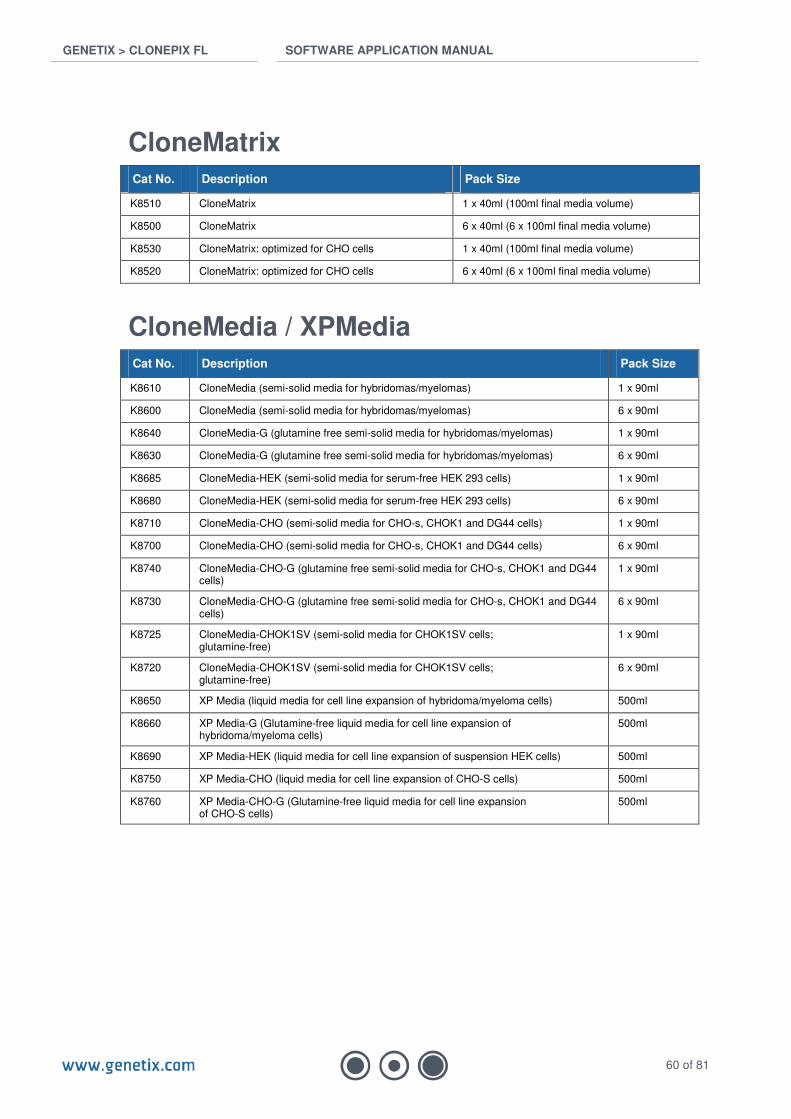
CloneMatrix Cat No. Description Pack Size
K8510 CloneMatrix 1 x 40ml (100ml final media volume)
K8500 CloneMatrix 6 x 40ml (6 x 100ml final media volume)
K8530 CloneMatrix: optimized for CHO cells 1 x 40ml (100ml final media volume)
K8520 CloneMatrix: optimized for CHO cells 6 x 40ml (6 x 100ml final media volume)
CloneMedia / XPMedia Cat No. Description Pack Size
K8610 CloneMedia (semi-solid media for hybridomas/myelomas) 1 x 90ml
K8600 CloneMedia (semi-solid media for hybridomas/myelomas) 6 x 90ml
K8640 CloneMedia-G (glutamine free semi-solid media for hybridomas/myelomas) 1 x 90ml
K8630 CloneMedia-G (glutamine free semi-solid media for hybridomas/myelomas) 6 x 90ml
K8685 CloneMedia-HEK (semi-solid media for serum-free HEK 293 cells) 1 x 90ml
K8680 CloneMedia-HEK (semi-solid media for serum-free HEK 293 cells) 6 x 90ml
K8710 CloneMedia-CHO (semi-solid media for CHO-s, CHOK1 and DG44 cells) 1 x 90ml
K8700 CloneMedia-CHO (semi-solid media for CHO-s, CHOK1 and DG44 cells) 6 x 90ml
K8740 CloneMedia-CHO-G (glutamine free semi-solid media for CHO-s, CHOK1 and DG44 cells)
1 x 90ml
K8730 CloneMedia-CHO-G (glutamine free semi-solid media for CHO-s, CHOK1 and DG44 cells)
6 x 90ml
K8725 CloneMedia-CHOK1SV (semi-solid media for CHOK1SV cells; glutamine-free)
1 x 90ml
K8720 CloneMedia-CHOK1SV (semi-solid media for CHOK1SV cells; glutamine-free)
6 x 90ml
K8650 XP Media (liquid media for cell line expansion of hybridoma/myeloma cells) 500ml
K8660 XP Media-G (Glutamine-free liquid media for cell line expansion of hybridoma/myeloma cells)
500ml
K8690 XP Media-HEK (liquid media for cell line expansion of suspension HEK cells) 500ml
K8750 XP Media-CHO (liquid media for cell line expansion of CHO-S cells) 500ml
K8760 XP Media-CHO-G (Glutamine-free liquid media for cell line expansion of CHO-S cells)
500ml
GENETIX > CLONEPIX FL SOFTWARE APPLICATION MANUAL
61 of 81
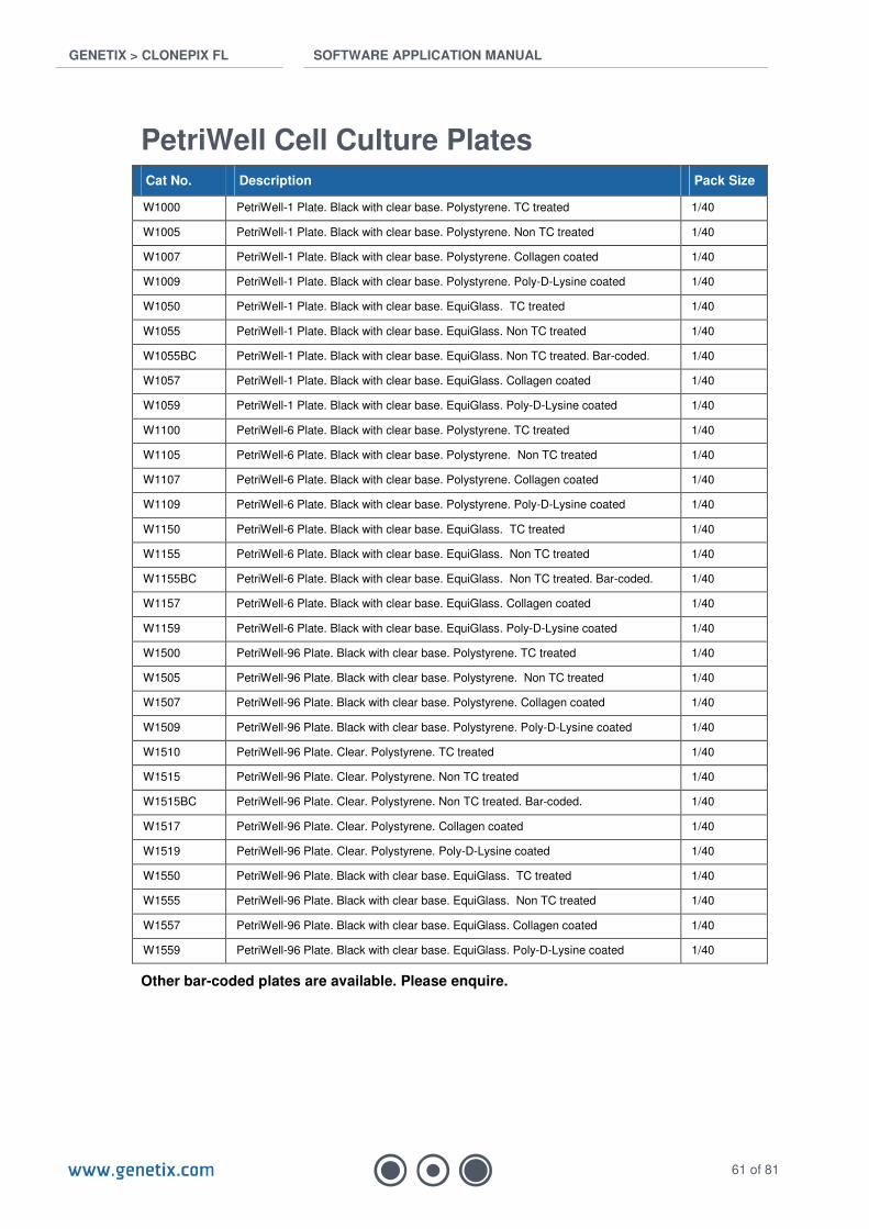
PetriWell Cell Culture Plates Cat No. Description Pack Size
W1000 PetriWell-1 Plate. Black with clear base. Polystyrene. TC treated 1/40
W1005 PetriWell-1 Plate. Black with clear base. Polystyrene. Non TC treated 1/40
W1007 PetriWell-1 Plate. Black with clear base. Polystyrene. Collagen coated 1/40
W1009 PetriWell-1 Plate. Black with clear base. Polystyrene. Poly-D-Lysine coated 1/40
W1050 PetriWell-1 Plate. Black with clear base. EquiGlass. TC treated 1/40
W1055 PetriWell-1 Plate. Black with clear base. EquiGlass. Non TC treated 1/40
W1055BC PetriWell-1 Plate. Black with clear base. EquiGlass. Non TC treated. Bar-coded. 1/40
W1057 PetriWell-1 Plate. Black with clear base. EquiGlass. Collagen coated 1/40
W1059 PetriWell-1 Plate. Black with clear base. EquiGlass. Poly-D-Lysine coated 1/40
W1100 PetriWell-6 Plate. Black with clear base. Polystyrene. TC treated 1/40
W1105 PetriWell-6 Plate. Black with clear base. Polystyrene. Non TC treated 1/40
W1107 PetriWell-6 Plate. Black with clear base. Polystyrene. Collagen coated 1/40
W1109 PetriWell-6 Plate. Black with clear base. Polystyrene. Poly-D-Lysine coated 1/40
W1150 PetriWell-6 Plate. Black with clear base. EquiGlass. TC treated 1/40
W1155 PetriWell-6 Plate. Black with clear base. EquiGlass. Non TC treated 1/40
W1155BC PetriWell-6 Plate. Black with clear base. EquiGlass. Non TC treated. Bar-coded. 1/40
W1157 PetriWell-6 Plate. Black with clear base. EquiGlass. Collagen coated 1/40
W1159 PetriWell-6 Plate. Black with clear base. EquiGlass. Poly-D-Lysine coated 1/40
W1500 PetriWell-96 Plate. Black with clear base. Polystyrene. TC treated 1/40
W1505 PetriWell-96 Plate. Black with clear base. Polystyrene. Non TC treated 1/40
W1507 PetriWell-96 Plate. Black with clear base. Polystyrene. Collagen coated 1/40
W1509 PetriWell-96 Plate. Black with clear base. Polystyrene. Poly-D-Lysine coated 1/40
W1510 PetriWell-96 Plate. Clear. Polystyrene. TC treated 1/40
W1515 PetriWell-96 Plate. Clear. Polystyrene. Non TC treated 1/40
W1515BC PetriWell-96 Plate. Clear. Polystyrene. Non TC treated. Bar-coded. 1/40
W1517 PetriWell-96 Plate. Clear. Polystyrene. Collagen coated 1/40
W1519 PetriWell-96 Plate. Clear. Polystyrene. Poly-D-Lysine coated 1/40
W1550 PetriWell-96 Plate. Black with clear base. EquiGlass. TC treated 1/40
W1555 PetriWell-96 Plate. Black with clear base. EquiGlass. Non TC treated 1/40
W1557 PetriWell-96 Plate. Black with clear base. EquiGlass. Collagen coated 1/40
W1559 PetriWell-96 Plate. Black with clear base. EquiGlass. Poly-D-Lysine coated 1/40
Other bar-coded plates are available. Please enquire.

GENETIX > CLONEPIX FL SOFTWARE APPLICATION MANUAL
62 of 81
Other Cat No. Description Pack Size
K2505 aQu Clean pin cleaning solution 1L
K8080 Genetix Sterilizing Agent (1L per Sachet) 10
K8085 Genetix Sterilizing Agent (1L per Sachet) 50
K8150 CaliBeads: Fluorescent beads for ClonePix FL. 200µm diameter. Pan-wavelength.
100ml
K8010 Adherent Cell Picking Reagent – Type A 1 x 500ml
K8020 Adherent Cell Picking Reagent – Type B 1 x 500ml
K8030 Adherent Cell Picking Reagent – Type C 1 x 500ml
K8040 Adherent Cell Picking Reagent – Type D 1 x 500ml
K8005 Adherent Cell Picking Reagent Test Kit Types A – D 4 x 250ml
K8100 ProbeClean: Fluorescently labeled Antibody Clean-up Columns 50

GENETIX > CLONEPIX FL SOFTWARE APPLICATION MANUAL
63 of 81
Appendix A: Imaging Definitions
Statistics for Prime Configurations
Statistic Description Category Unit
Actual X The X co-ordinate of the centre of the feature in mm Position mm
Actual Y The Y co-ordinate of the centre of the feature in mm Position mm
Area The area covered by the feature (excluding 'child' features) in square mm
Morphology mm²
Axis Ratio The ratio of the minimum and maximum radiuses of the feature measured from 0 (very elongated) to 1 (a perfect circle)
Morphology
Block The identifier of the block of features this feature is associated with
General
Compactness A measure of how compact the feature is, measured from 0 (not compact) to 1 (a perfect circle)
Morphology
Deposit Barcode Barcode of the plate the colony has been deposited in Information
Deposit Well The well the colony has been deposited in Information
Edge Excluded Whether the colony center lies within the exclusion zone Position
Feature ID A unique identifier General
Group Group the feature is assigned to General
Image Column The column the image containing the feature is in Position
Image Row The row the image containing the feature is in Position
Intensity SD The standard deviation of the intensity of the pixels in the feature
Intensity
Manual Group Whether the feature was manually added to its current group
General
Mean Centre Intensity The mean intensity of the nine pixels at the centre of the feature
Intensity
Mean Intensity The mean intensity of all the pixels in the feature Intensity
Median Intensity The median intensity of all the pixels in the feature Intensity
Perimeter The length of the perimeter of the feature in mm Morphology mm
Picked Flag to signify if the colony has been picked. Information
Pixel Area The area covered by the feature (excluding 'child' features) in pixels
Morphology pixels
Pixel Average RMS The average (root mean square) radius of the feature in pixels
Morphology pixels
Pixel Perimeter The length of the perimeter of the feature in pixels Morphology pixels
Pixel Radius Max The maximum radius of the feature in pixels Morphology pixels
Pixel Radius Min The minimum radius of the feature in pixels Morphology pixels
Pixel Total Area The total area of the feature (including 'child' features) in pixels
Morphology pixels
Pixel X The X co-ordinate of the centre of the feature in pixels relative to the top left of the image
Position pixels
Pixel Y The Y co-ordinate of the centre of the feature in pixels relative to the top left of the image
Position pixels
Proximity The distance to the closest neighboring colony in the same image
Morphology mm
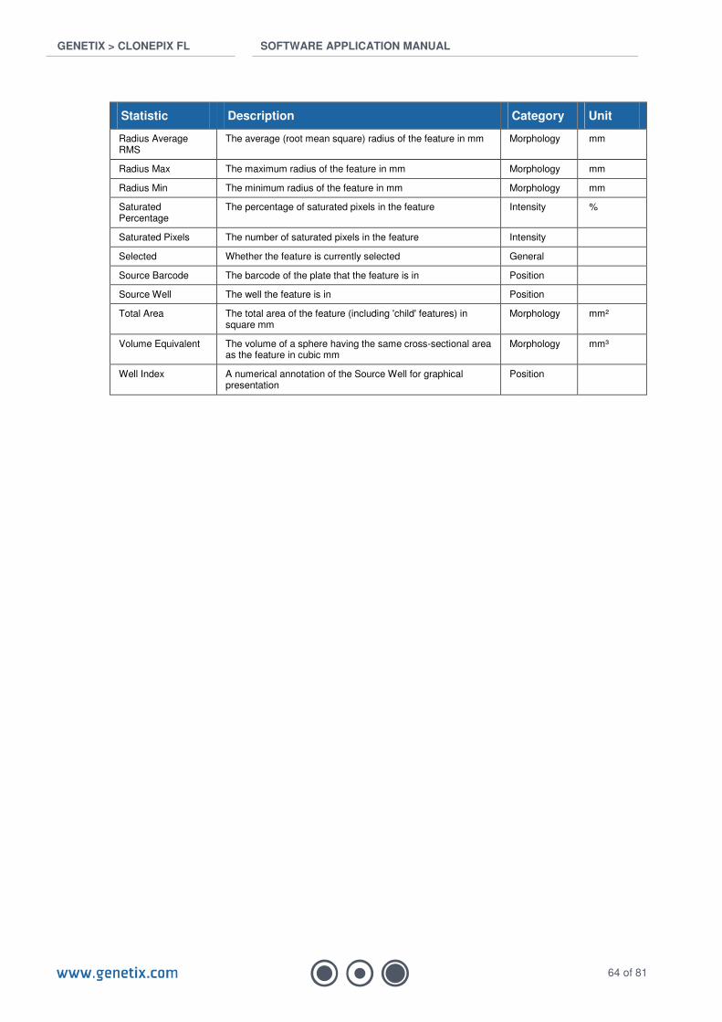
GENETIX > CLONEPIX FL SOFTWARE APPLICATION MANUAL
64 of 81
Statistic Description Category Unit
Radius Average RMS
The average (root mean square) radius of the feature in mm Morphology mm
Radius Max The maximum radius of the feature in mm Morphology mm
Radius Min The minimum radius of the feature in mm Morphology mm
Saturated Percentage
The percentage of saturated pixels in the feature Intensity %
Saturated Pixels The number of saturated pixels in the feature Intensity
Selected Whether the feature is currently selected General
Source Barcode The barcode of the plate that the feature is in Position
Source Well The well the feature is in Position
Total Area The total area of the feature (including 'child' features) in square mm
Morphology mm²
Volume Equivalent The volume of a sphere having the same cross-sectional area as the feature in cubic mm
Morphology mm³
Well Index A numerical annotation of the Source Well for graphical presentation
Position
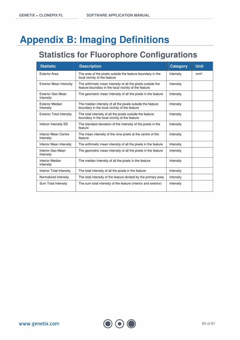
GENETIX > CLONEPIX FL SOFTWARE APPLICATION MANUAL
65 of 81
Appendix B: Imaging Definitions
Statistics for Fluorophore Configurations
Statistic Description Category Unit
Exterior Area The area of the pixels outside the feature boundary in the local vicinity of the feature
Intensity mm²
Exterior Mean Intensity The arithmetic mean intensity of all the pixels outside the feature boundary in the local vicinity of the feature
Intensity
Exterior Geo Mean Intensity
The geometric mean intensity of all the pixels in the feature Intensity
Exterior Median Intensity
The median intensity of all the pixels outside the feature boundary in the local vicinity of the feature
Intensity
Exterior Total Intensity The total intensity of all the pixels outside the feature boundary in the local vicinity of the feature
Intensity
Interior Intensity SD The standard deviation of the intensity of the pixels in the feature
Intensity
Interior Mean Centre Intensity
The mean intensity of the nine pixels at the centre of the feature
Intensity
Interior Mean Intensity The arithmetic mean intensity of all the pixels in the feature Intensity
Interior Geo Mean Intensity
The geometric mean intensity of all the pixels in the feature Intensity
Interior Median Intensity
The median intensity of all the pixels in the feature Intensity
Interior Total Intensity The total intensity of all the pixels in the feature Intensity
Normalized Intensity The total intensity of the feature divided by the primary area Intensity
Sum Total Intensity The sum total intensity of the feature (interior and exterior) Intensity
GENETIX > CLONEPIX FL SOFTWARE APPLICATION MANUAL
66 of 81
Appendix C: Guide to Fluorophore Configurations
The ClonePix FL acquires images of fluorescing colonies and generates a range of statistics from the images in order that the colonies can be screened to select the most ‘fit’. The user can choose which parameters to use to meet their definition of ‘fit’ – the software does not enforce any particular definition of what the ‘best’ colonies are.
Most users wish to select either the highest expressing colonies or those that are positive for a specific parameter. The software generates a variety of statistics to facilitate this. This appendix explains how these statistics are generated and provides advice on how they might be used.
Measuring Fluorescence The ClonePix FL software works on the principal that all colonies can be detected under white light. All of the detection algorithms in the software process the white light (Prime Probe) images to detect colony boundaries.
There are two principal advantages to this approach; 1) colonies that are not fluorescing can still be detected and taken into account when deciding which colonies to select and 2) knowing the boundaries of all colonies allows for a more rigorous approach to processing the fluorescent images.
Fluorescent colonies can be divided into two types; 1) those whose fluorescence is purely ‘internal’, i.e. within the colony boundary as determined from the white light image and 2) those whose fluorescence is also present outside the colony boundary.
Generating statistics for the first type of fluorescent colony is straightforward because for any given pixel in the image the pixel is either within the boundary of one colony or it is a background pixel and can be ignored. The only complication is determining what proportion of the pixel’s intensity is ‘real’ fluorescence and what proportion is ‘background’ fluorescence. Background fluorescence would exist even in the absence of any colonies since fluorescence images rarely have a background of zero – pure black.
Generating statistics for the second type of fluorescent colony (those whose fluorescence is also present outside the colony boundary) is more problematic. This is because when two or more of these colonies are close together, their fluorescence will mingle together and there is no deterministic mechanism to accurately decide what proportion of a given pixel’s intensity can be attributed to each colony. The problem is compounded as the density of colonies increases (i.e. when there are more colonies in each plate). Additionally, fluorescence from the second type of colony can affect the first type of colony, which can therefore no longer be assumed to be independent of other colonies.
Because of this difficulty, the ClonePix FL software does not attempt to determine what proportion of intensity of pixels outside of colony boundaries comes from any particular colony. Instead, all of the pixels surrounding each colony are included, as explained below. This results in some pixels being included in the total for several colonies, but this isn’t a shortcoming as will become clear.
Finally, it is important to appreciate that the ClonePix FL measures relative fluorescence, not absolute fluorescence. This means that fluorescent statistics can only meaningfully be compared when generated from the same plate or batch of identical plates at the same time. It is not necessarily meaningful to compare fluorescent statistics between different plates imaged on different days. This is because a number of things can vary that affect fluorescence, for example exposure time. Varying the exposure time used when acquiring fluorescent images will increase or decrease the absolute values of the fluorescent statistics. However, all colonies will in general get brighter or darker thus their brightness relative to each other is unaffected.

GENETIX > CLONEPIX FL SOFTWARE APPLICATION MANUAL
67 of 81
Example of Fluorescent Statistic Generation The white light image (right) shows two colonies close together. Their approximate boundaries, as determined by the colony detection algorithm are shown in pink. The corresponding fluorescent image is shown (right) with the colony detection algorithm in pink overlaid. A number of fluorescent statistics can be generated from this directly. Note: a background subtraction algorithm is applied to all fluorescent images before intensity statistics are generated. This algorithm seeks to determine what level of fluorescence there would be in the absence of any colonies, and removes this from the image so that the intensity statistics only include ‘real’ fluorescence.
Interior Intensity Statistics The simplest statistic is Interior Total Intensity. This is the sum of the intensities of all of the pixels of the fluorescent image within the colony boundary from the matching white light image. Larger colonies will have larger totals because they are larger. This statistic is not therefore especially useful on its own but several other statistics are derived from it. Interior Mean Intensity is Interior Total Intensity divided by colony area (in pixels). It is the ‘average’ brightness of all pixels within the colony, or the arithmetic mean. Since it does take account of area, this statistic can be used to compare colonies with different areas. In fact, this is probably the most powerful statistic (along with Interior Median Intensity, described below) since colonies with a high Interior Mean Intensity are overwhelmingly likely to be bright colonies – rather than simply faint colonies that happen to be near a bright colony that is dispersing fluorescence into the surrounding medium.
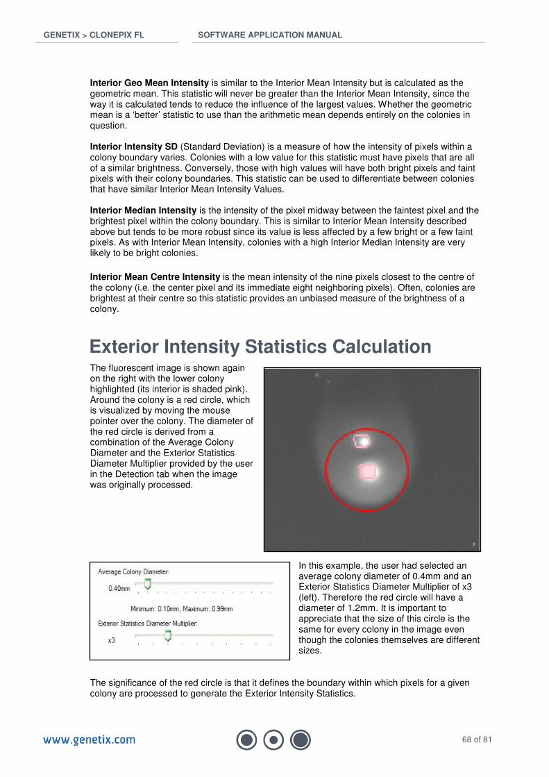
GENETIX > CLONEPIX FL SOFTWARE APPLICATION MANUAL
68 of 81
Interior Geo Mean Intensity is similar to the Interior Mean Intensity but is calculated as the geometric mean. This statistic will never be greater than the Interior Mean Intensity, since the way it is calculated tends to reduce the influence of the largest values. Whether the geometric mean is a ‘better’ statistic to use than the arithmetic mean depends entirely on the colonies in question. Interior Intensity SD (Standard Deviation) is a measure of how the intensity of pixels within a colony boundary varies. Colonies with a low value for this statistic must have pixels that are all of a similar brightness. Conversely, those with high values will have both bright pixels and faint pixels with their colony boundaries. This statistic can be used to differentiate between colonies that have similar Interior Mean Intensity Values. Interior Median Intensity is the intensity of the pixel midway between the faintest pixel and the brightest pixel within the colony boundary. This is similar to Interior Mean Intensity described above but tends to be more robust since its value is less affected by a few bright or a few faint pixels. As with Interior Mean Intensity, colonies with a high Interior Median Intensity are very likely to be bright colonies.
Interior Mean Centre Intensity is the mean intensity of the nine pixels closest to the centre of the colony (i.e. the center pixel and its immediate eight neighboring pixels). Often, colonies are brightest at their centre so this statistic provides an unbiased measure of the brightness of a colony.
Exterior Intensity Statistics Calculation The fluorescent image is shown again on the right with the lower colony highlighted (its interior is shaded pink). Around the colony is a red circle, which is visualized by moving the mouse pointer over the colony. The diameter of the red circle is derived from a combination of the Average Colony Diameter and the Exterior Statistics Diameter Multiplier provided by the user in the Detection tab when the image was originally processed.
In this example, the user had selected an average colony diameter of 0.4mm and an Exterior Statistics Diameter Multiplier of x3 (left). Therefore the red circle will have a diameter of 1.2mm. It is important to appreciate that the size of this circle is the same for every colony in the image even though the colonies themselves are different sizes.
The significance of the red circle is that it defines the boundary within which pixels for a given colony are processed to generate the Exterior Intensity Statistics.

GENETIX > CLONEPIX FL SOFTWARE APPLICATION MANUAL
69 of 81
Exterior Intensity Statistics are generated by firstly considering all of the pixels within the red circle. Following this, any pixels within the colony of interest’s boundary are excluded (the pixels shaded in pink). Next, all of the pixels that lie within any other colonies are excluded. So in the image on the right, all of the pixels within the boundary of the second unshaded colony would be excluded. This is because any fluorescence within a neighboring colony’s boundary is quite likely to have come from the neighboring colony.
What remains are the pixels that are local to the colony of interest but not within any other colony boundary (highlighted in green in the image). These are the pixels that are used to generate the ‘exterior intensity’ statistics.
Note that if the colony is larger than the Average Colony Diameter specified by the user or if the colony is an irregular shape, it is possible that some of the pixels within the colony boundary would lie outside the red circle. In those circumstances, the red circle will not be a good approximation of the area ‘local’ to the colony. Also it is not clear how to meaningfully compare irregular shaped colonies with the more circular shaped colonies because it is unlikely that the ‘local’ area values produced can be used for comparative purposes.
Neighboring colonies are treated in exactly the same way. In the image to the right, the top colony (shaded in pink) has been selected. Again, the red circle overlaps the lower colony. This means that many pixels will be used to generate exterior statistics for both colonies.
In this example both colonies are fluorescing and dispersing their fluorescence into the local medium so, for the pixels close to both colonies, it is not clear what proportion of the intensity of each pixel is derived from which colony. The area of fluorescence around the colonies looks quite uniform implying that the fluorescence from each colony isn’t cumulative. This suggests that counting the intensities of the pixels twice (once from each colony) would be a reasonable approach.
Exterior Intensity Statistics Exterior Area (mm
2) is the area of the ‘exterior’ pixels (those shaded green in the image
above). It could be used to exclude colonies that are in crowded regions of the plate. A low value for a given colony compared to other colonies in the image will indicate that the exterior intensity statistics for that colony may not be accurate. It is not in any way a measure of the actual size of the halo of fluorescence for any colony.
Exterior Total Intensity is the sum of the intensities of all of the ‘exterior’ pixels. If there are neighbouring colonies within the red circle, this value will be lower. On its own, this statistic is not very useful since it cannot be used comparatively with other colonies.
Exterior Mean Intensity is the Exterior Total Intensity divided by the number of pixels in the exterior area (arithmetic mean). This statistic provides a good approximation of how bright the area immediately surrounding a given colony is, though there is no implication that the brightness is coming from the colony as opposed to one or more of its neighbors.

GENETIX > CLONEPIX FL SOFTWARE APPLICATION MANUAL
70 of 81
Exterior Geo Mean Intensity is similar to the Exterior Mean Intensity but is the geometric mean. See the explanation of Interior Geo Mean Intensity for further details.
Exterior Median Intensity is the intensity of the pixel midway between the brightest and the faintest pixel within the exterior pixels. Just as the Interior Median Intensity is more robust than the Interior Mean Intensity, so the Exterior Median Intensity is more robust than Exterior Mean Intensity.
Sum Total Intensity seeks to approximate the sum of the Exterior Total Intensity and Interior Total Intensity if there were no neighboring colonies within the red circle. Instead of using the actual Exterior Total Intensity it uses the Exterior Mean Intensity multiplied by the number of pixels within the red circle. The calculation also excludes the pixels within the colony of interest’s boundary but includes any pixels in neighboring colonies in the red circle. If this calculation were not taken into account it would not be meaningful to compare Sum Total Intensity between colonies because the value would vary depending on the presence of neighboring colonies.
Normalized Intensity is Sum Total Intensity divided by colony area (in pixels). The highest secreting colonies will have the highest values here but unfortunately in practice normalizing by area biases the statistic in favor of small colonies rather than bright colonies. This is because the interior intensity is always much brighter than the exterior intensity which decreases exponentially from the colony boundary.

GENETIX > CLONEPIX FL SOFTWARE APPLICATION MANUAL
71 of 81
Appendix D: Licensing
Requesting a license
If you see the following message when booting ClonePix FL software, you will need to request a new license. This is easily done by creating a license request and then e-mailing it to Genetix.
.
• Click YES. This brings up the following window:
• Select “Request a new license” and click Next. The software will prompt you to save a license request file:

GENETIX > CLONEPIX FL SOFTWARE APPLICATION MANUAL
72 of 81
• Save file to a location where it is accessible to e-mail.
• E-mail this *.req file to a Genetix representative.
• Click Finish.
.

GENETIX > CLONEPIX FL SOFTWARE APPLICATION MANUAL
73 of 81
Installing a license • When you receive a license file back from the Genetix representative, save the file to a
place accessible on the computer of your Genetix instrument.
• Re-open the ClonePix FL software.
• Select “Install a license file”:
• Click Next.
• Click Open, and browse to the location where the license (*.License) file was saved.
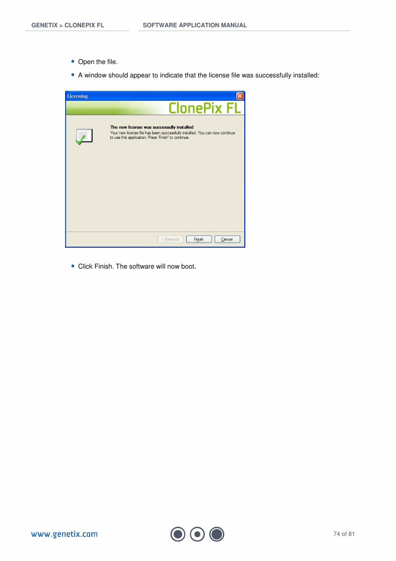
GENETIX > CLONEPIX FL SOFTWARE APPLICATION MANUAL
74 of 81
• Open the file.
• A window should appear to indicate that the license file was successfully installed:
• Click Finish. The software will now boot.
GENETIX > CLONEPIX FL SOFTWARE APPLICATION MANUAL
75 of 81
Appendix E: Reviewing and Exporting Data
The ClonePix FL generates a large quantity of data, in the form of images, statistics and logs of samples transferred between well plates. This appendix explains the various options available for accessing this data.
Review Results The simplest form of access is to use Review Results via the icon on the main screen. This provides access to all images and statistics generated on the ClonePix FL, including colony detection overlays and settings. Review Results is the best way to access historical data, since it is able to present the data in the way it was originally generated, including links between graphs, data tables and images. For Pick Runs, an extra tab called Output Results is displayed to present destination plate, well and barcode information. Pick Run data are non-modifiable to provide an accurate record of the run. Imaging Run data are modifiable to permit free play within the Detection and Group tabs, although such changes are not saved when the file is closed.
Graphs and images can be exported from within Review Results and either copied to the Windows clipboard or saved as a file. They can easily be pasted into presentations, etc. as required.
Statistics can also be exported, with a choice of data formats including comma separated values (CSV), XML and Excel-XML. Statistics are exported by clicking the ‘Export Statistics’ button on the ‘Statistics’ tab.
Remote Data Viewer This is an optional software program for accessing ClonePix FL results remotely on another PC or laptop (order code: SL4950-A01). The format is identical to the Review Results feature in ClonePix FL software (see above), and permits results to be accessed on ClonePix FL via a network or copies of runs transferred elsewhere.
Results Report A Results Report can be generated to provide a concise summary of any run including user-defined settings. It can be created from within Review Results or the Remote Data Viewer and is generated in XML format so that it can be opened in a web browser and easily printed or stored electronically. Results Reports are generated by clicking the ‘Generate Report’ button on the ‘Statistics’ tab.
Data Tracking Logs Important note: The editing of Data Tracking Logs requires entering the Configuration section of ClonePix FL. It is strongly advised that this should only be done under supervision by a Genetix Approved Engineer.
A Data Tracking log file is created automatically for each run. This is an XML file with the same schema used by other Genetix instruments. It includes some statistical information for each colony along with a ‘replicate’ element for each transfer from a source well to a destination well.

GENETIX > CLONEPIX FL SOFTWARE APPLICATION MANUAL
76 of 81
The Data Tracking log may be of interest for those wishing to automatically process the transfer of samples between plates. However the Automatic Logs option may be more useful (see below).
Data Tracking logs are generated in the ‘Data Tracking’ sub folder of the configuration folder. The configuration folder is stored under the local applications data folder. On Windows XP, the location is usually:
“C:\Documents and Settings\All Users\Application Data\Genetix\Fusion\ClonePix FL\Data Tracking”
One file is generated for each imaging or picking run. The file name is derived from the data and time of the run, and the file extension is XML.
Automatic Logs Important note: The editing of Automatic Logs requires entering the Configuration section of ClonePix FL. It is strongly advised that this should only be done under supervision by a Genetix Approved Engineer.
‘Auto Logs’ can be generated by the system for each run, and some level of control of their content is provided. Auto Logs are not generated by default, but when enabled one log is generated for each run in a location specified by the user.
The log is broadly the same format as that provided by the ‘Export Statistics’ button in Review Results or the Remote Data Viewer.
The settings to control Auto Logs are accessible from the ‘PickVerb’ in the Verbs section of the Configuration screen (available from the ‘Tools’ menu of the ClonePix FL software).
There are four settings which control Auto Logs:
AutoLog
Controls whether Auto Logs are generated. Set to ‘True’ to enable.
AutoLogPath
The location to output the logs to. It must be a fully qualified path of a folder that the operator of the software has write access to. This can be a mapped drive, but be aware that if the drive is not available during a run, the run could abort abnormally.
GENETIX > CLONEPIX FL SOFTWARE APPLICATION MANUAL
77 of 81
ExportFileType
The format of file to generate. Can be comma separated values (CSV), XML or Excel-XML.
PickedColoniesOnly
Whether to only include in the output file statistics for colonies that were actually picked (‘True’) or all colonies (‘False’).
One folder is generated for each run, whose name is derived from the data and time of the run. A file is created in the folder with the name ‘Auto.csv’ or ‘Auto.xml’ depending upon the file type selected.
Raw Data The default location for raw data (TIF images and XML files) is: “C:\image archive”. Viewing data from this location is not recommended.

GENETIX > CLONEPIX FL SOFTWARE APPLICATION MANUAL
78 of 81
Appendix F: Glossary of Terms Barcode
A unique label for source and destination microplates. Recommended barcoded plate types for colonies suspended in semi-solid medium are PetriWell-1 plates (Catalogue number W1055BC) and PetriWell-6 plates (Catalogue number W1155BC)
Colony
A clonal group of cells, typically of mammalian origin, that have grown either adherently or suspended in semi-solid medium.
Datum Point
A series of X, Y, Z co-ordinates that define a set position on the Robot bed.
Destination plate
96-well microplate(s) prefilled with liquid medium to collect picked colonies.
Dispersal
Dispersal Option separates out the cells of a picked colony by aspirating and dispensing in the destination plate.
Epi-illumination
The white light option normally used for configuring the robot and for visualising colonies during picking, using LEDs located under the source plate being imaged.
EquiGlass
A high quality polymer used as the base material for Genetix PetriWell plates. It has excellent properties for optimal fluorescent imaging.
Halogen dryer
Proprietary ultra-high temperature dryer used as part of the Pin Sanitise system.
Image Acquisition
The capturing of images using pre-defined Acquisition Options.
Image Archive
Default location for Pick Run and Imaging Run images and data. Accessible via Review Results.
LED intensity
ClonePix FL uses only LEDs for consistent and reliable imaging. The intensity of the LEDs can be adjusted by the user to control image exposure under the Acquisition tab.
LIMS
Laboratory Information Management System.
LiveDetect
A reagent for visualising only live cells. Can be used as a fluorescent alternative to imaging colonies by white light. Catalogue number K8300.
.gfp file
Format used to save a Process.
.gft file
Format used to save a Process Template.
Interior Light
Illuminates the interior of the instrument. Can be activated or deactivated at any time using the
GENETIX > CLONEPIX FL SOFTWARE APPLICATION MANUAL
79 of 81
Interior Light icon in the bottom right corner of the screen. Interior Light is not used for imaging and will automatically switch off during imaging
PetriWell-1 plate
Genetix single well plate optimized for visualizing plated colonies. The non-treated type (Catalogue number W1055) are recommended for colonies suspended in semi-solid medium. The TC-treated
type (Catalogue number W1050) are recommended for colonies grown as adherent monolayers.
PetriWell-6 plate
Genetix 6 well plate optimized for visualizing plated colonies. The non-treated type (Catalogue number W1155) are recommended for colonies suspended in semi-solid medium. The TC-treated type
(Catalogue number W1150) are recommended for colonies grown as adherent monolayers.
Picking Pins
Reusable stainless steel tools used to collect colonies. F1 pins have an internal tip diameter of 400µm and are for picking suspended colonies. F2 pins have an internal tip diameter of 700µm and are for picking adherent colonies (monolayers).
Primary Pin
The picking pin nearest the front of the robot. All other pins are aligned relative to this one.
Prime Configuration
The Acquisition Option that will be used for colony detection. Normally this is based on white light imaging.
Prime Probe
The type of illumination that will be used for colony detection. Normally, this will be white light by transillumination (trans). The Prime Probe is set up by creating a Prime Configuration.
Process
A standard program for ClonePix FL to carry out a task such as a series of similar experiments, or a maintenance task. A Process is saved as a .gfp file.
Proximity Indicators
Red lines between colonies on the image that show the nearest neighbour for each colony. Note: This feature is not the same as the colony exclusion feature in Groups.
Remote Data Viewer
An optional software program (order code: SL4950-A01) for accessing ClonePix FL results remotely. Please contact Customer Support for further information.
Semi-solid medium
A viscous cell culture medium such as CloneMedia used to immobilize cells in suspension to permit growth of clonal colonies.
Source plate
One- or 6-well microplate(s) containing colonies for picking.
Sterilizing Agent
Recommended for sterilizing ClonePix FL and its components and accessories. Catalogue number K8080.
Template
A program from which Processes can be generated. A Template is saved as a .gft file.
Transillumination
The white light option normally used to detect colonies using LEDs positioned on the robot head.

GENETIX > CLONEPIX FL SOFTWARE APPLICATION MANUAL
80 of 81
Wash bottle
4 liter bottle of sterile water used to purge the fluid system (1 liter in some older systems).
Waste bottle
4 liter bottle used to collect purged fluid (1 liter in some older systems).
White Light
Full spectrum LED illumination, of which there are two options: Transillumination (Trans) is normally used to detect colonies. Epi-illumination is normally used for configuring the robot and for visualising colonies during picking.
X Drive
Robot axis running from right to left.
XML
Extensible Markup Language. A simple text format derived from SGML Originally designed to meet the challenges of large-scale electronic publishing, XML is also used in the exchange of a wide variety of data on the Web.
Y Drive
Robot axis running from back to front.
Z Drive
Robot axis running vertically from high to low on the Robot bed.

GENETIX > CLONEPIX FL SOFTWARE APPLICATION MANUAL
81 of 81
Contact Details
Corporate Headquarters Genetix Ltd
Queensway, New Milton Hampshire BH25 5NN, UK
Tel: +44 (0) 1425 624 600 Fax: +44 (0) 1425 624 700
Visit www.genetix.com for contact details of your nearest Genetix sales and support office.
Trademarks:
CellReporter, ClonePix and CloneSelect are trademarks of trademark of Genetix Ltd., UK.
Notice
ClonePix FL and its related applications are covered by US Patent No 7,310,147 and pending patent applications filed by Genetix. The purchase of this product conveys to the purchaser the limited, non-exclusive and non-transferable right under these patent rights to use the screening method as claimed for research purposes only in conjunction with ClonePix FL. No other licence is granted to the purchaser whether expressly, by implication, by estoppel or otherwise. In particular, the purchase of this product does not include nor carry any right or license to use, develop, or otherwise exploit this product commercially, and no rights are conveyed to the purchaser to use the product, its components or the method for any other purposes, including without limitation, provision of services to a third party or generation of commercial databases. For information concerning the availability of licences for other uses, please contact Genetix Limited Queensway, New Milton, Hants BH25 5NN T: +44 (0) 1425 624600 – F: +44 (0) 1425 624700
Copyright © 2010 Genetix Ltd
All rights reserved. No part of this publication may be reproduced, stored in a retrieval system, or transmitted, in any form by any means, electronic, mechanical, by photocopying, recording, or otherwise, without the prior written permission of Genetix Ltd.
Information furnished by Genetix Ltd is believed to be accurate and reliable; however, no responsibility is assumed by Genetix Ltd, for its use; nor for any infringements of patents or other rights of third parties which may result from its use. No license is granted by implication or otherwise under any patent rights of Genetix Ltd.
Revised: 17 June 2010