Embed Size (px)
Citation preview
Proclaim™ Implantable Pulse Generator Models 3660, 3661, 3662, 3663, 3665, 3667
Clinician's Manual

Unless otherwise noted, ™ indicates that the name is a trademark of, or licensed to, St. Jude Medical or one of its subsidiaries. ST. JUDE MEDICAL and the nine-squares symbol are trademarks and service marks of St. Jude Medical, LLC and its related companies.
Pat. http://patents.sjm.com
© 2017 St. Jude Medical, LLC. All Rights Reserved.
i
Contents
Prescription and Safety Information ........................................................................... 1 Intended Use .................................................................................................................... 1 Indications for Use ............................................................................................................ 1 Contraindications ............................................................................................................... 1 MRI Safety Information ...................................................................................................... 1 Warnings .......................................................................................................................... 1 Precautions ....................................................................................................................... 2 Adverse Effects.................................................................................................................. 4
System Overview ....................................................................................................... 4 Product Description ................................................................................................... 5
Package Contents .............................................................................................................. 6 Identifying the IPG ............................................................................................................. 6
Directions for Use...................................................................................................... 6 Creating an IPG Pocket ...................................................................................................... 7 Connecting a Lead or Extension to the IPG .......................................................................... 7 Implanting the IPG ............................................................................................................ 9 Replacing the IPG ............................................................................................................. 9 Disposing of Explanted Components ................................................................................. 10
Checking the Status of the IPG Battery ..................................................................... 10 Technical Support ................................................................................................... 10 Appendix A: Product Specifications ......................................................................... 11
Storage Specifications ...................................................................................................... 11 Product Materials ............................................................................................................ 11 IPG Specifications ........................................................................................................... 12 Compatibility Guidelines for IPGs with Compatible Headers................................................ 13
Appendix B: System Components and Accessories .................................................. 14 IPGs ............................................................................................................................... 14 Programmers and Controllers ........................................................................................... 14 Leads and Extensions ...................................................................................................... 14 Adapters ......................................................................................................................... 15 Trial System .................................................................................................................... 15
Appendix C: Battery Longevity Information ............................................................... 16 Energy Factors for Tonic Stimulation Parameters ............................................................... 17 Energy Factors for BurstDR™ Stimulation Parameters ....................................................... 21 Battery Longevity Graphs ................................................................................................. 22
Appendix D: Regulatory Statements ......................................................................... 24 Disposal Guidelines for Battery-Powered Devices .............................................................. 24 Statement of FCC Compliance .......................................................................................... 24 Statement of Compliance With License-Exempt RSS Standard (Canada) ............................. 24 Identification Information for Product Registration ............................................................. 25 Wireless Technology Information ...................................................................................... 25 Radio Transmitter, Cables, Transducers ........................................................................... 25 Quality of Service for Wireless Technology ......................................................................... 26
ii
Appendix E: Symbols and Definitions ....................................................................... 27 Additional Symbols for Product Labels .............................................................................. 29
Appendix F: CE Mark Date ....................................................................................... 29
1
Prescription and Safety Information Read this section to gather important prescription and safety information.
Intended Use This neurostimulation system is designed to deliver low-intensity electrical impulses to nerve structures. The system is intended to be used with leads and associated extensions that are compatible with the system.
Indications for Use This neurostimulation system is indicated as an aid in the management of chronic, intractable pain of the trunk and/or limbs, including unilateral or bilateral pain associated with the following: failed back surgery syndrome and intractable low back and leg pain.
Contraindications This system is contraindicated for patients who are unable to operate the system or who have failed to receive effective pain relief during trial stimulation.
MRI Safety Information Some models of this system are Magnetic Resonance (MR) Conditional, and patients with these devices may be scanned safely with magnetic resonance imaging (MRI) when the conditions for safe scanning are met. For more information about MR Conditional neurostimulation components and systems, including equipment settings, scanning procedures, and a complete listing of conditionally approved components, refer to the MRI procedures clinician's manual for neurostimulation systems (available online at manuals.sjm.com). For more information about MR Conditional products, visit the St. Jude Medical product information page at sjm.com/MRIReady.
Warnings The following warnings apply to these components.
Poor surgical risks. Neurostimulation should not be used on patients who are poor surgical risks or patients with multiple illnesses or active general infections.
Magnetic resonance imaging (MRI). Some patients may be implanted with the components that make up a Magnetic Resonance (MR) Conditional system, which allows them to receive an MRI scan if all the requirements for the implanted components and for scanning are met. A physician can help determine if a patient is eligible to receive an MRI scan by following the requirements provided by St. Jude Medical. Physicians should also discuss any risks of MRI with patients.
Patients without an MR Conditional neurostimulation system should not be subjected to MRI because the electromagnetic field generated by an MRI may damage the device electronics and induce voltage through the lead that could jolt or shock the patient.
Diathermy therapy. Do not use short-wave diathermy, microwave diathermy, or therapeutic ultrasound diathermy (all now referred to as diathermy) on patients implanted with a neurostimulation system. Energy from diathermy can be transferred through the implanted system and cause tissue damage at the location of the implanted electrodes, resulting in severe injury or death.
Diathermy is further prohibited because it may also damage the neurostimulation system components. This damage could result in loss of therapy, requiring additional surgery for system implantation and replacement. Injury or damage can occur during diathermy treatment whether
2
the neurostimulation system is turned on or off.
Electrosurgery. To avoid harming the patient or damaging the neurostimulation system, do not use monopolar electrosurgery devices on patients with implanted neurostimulation systems. Before using an electrosurgery device, place the device in Surgery Mode using the patient controller app or clinician programmer app. Confirm the neurostimulation system is functioning correctly after the procedure.
During implant procedures, if electrosurgery devices must be used, take the following actions: Use bipolar electrosurgery only.
Complete any electrosurgery procedures before connecting the leads or extensions to the neurostimulator.
Keep the current paths from the electrosurgery device as far from the neurostimulation system as possible.
Set the electrosurgery device to the lowest possible energy setting.
Confirm that the neurostimulation system is functioning correctly during the implant procedure and before closing the neurostimulator pocket.
Implanted cardiac systems. Physicians need to be aware of the risk and possible interaction between a neurostimulation system and an implanted cardiac system, such as a pacemaker or defibrillator. Electrical pulses from a neurostimulation system may interact with the sensing operation of an implanted cardiac system, causing the cardiac system to respond inappropriately. To minimize or prevent the implanted cardiac system from sensing the output of the neurostimulation system, (1) maximize the distance between the implanted systems; (2) verify that the neurostimulation system is not interfering with the functions of the implanted cardiac system; and (3) avoid programming either device in a unipolar mode (using the device’s can as an anode) or using neurostimulation system settings that interfere with the function of the implantable cardiac system.
Pediatric use. Safety and effectiveness of neurostimulation for pediatric use have not been established.
Pregnancy and nursing. Safety and effectiveness of neurostimulation for use during pregnancy and nursing have not been established.
Device components. The use of components not approved for use by St. Jude Medical with this system may result in damage to the system and increased risk to the patient.
Case damage. Do not handle the IPG if the case is pierced or ruptured because severe burns could result from exposure to battery chemicals.
IPG disposal. Return all explanted IPGs to St. Jude Medical for safe disposal. IPGs contain batteries as well as other potentially hazardous materials. Do not crush, puncture, or burn the IPG because explosion or fire may result.
Precautions The following precautions apply to these components.
General Precautions Clinician training. Implanting physicians should be experienced in the diagnosis and treatment of chronic pain syndromes and have undergone surgical and device implantation training.
Patient selection. It is extremely important to select patients appropriately for neurostimulation. Thorough psychiatric screening should be performed. Patients should not be dependent on drugs and should be able to operate the neurostimulation system.
3
Infection. Follow proper infection control procedures. Infections related to system implantation might require that the device be explanted.
Electromagnetic interference (EMI). Some equipment in home, work, medical, and public environments can generate EMI that is strong enough to interfere with the operation of a neurostimulation system or damage system components. Patients should avoid getting too close to these types of EMI sources, which include the following examples: commercial electrical equipment (such as arc welders and induction furnaces), communication equipment (such as microwave transmitters and high-power amateur transmitters), high-voltage power lines, radiofrequency identification (RFID) devices, and some medical procedures (such as therapeutic radiation and electromagnetic lithotripsy).
Security, antitheft, and radiofrequency identification (RFID) devices. Some antitheft devices, such as those used at entrances or exits of department stores, libraries, and other public places, and airport security screening devices may affect stimulation. Additionally, RFID devices, which are often used to read identification badges, as well as some tag deactivation devices, such as those used at payment counters at stores and loan desks at libraries, may also affect stimulation. Patients who are implanted with nonadjacent multiple leads and patients who are sensitive to low stimulation thresholds may experience a momentary increase in their perceived stimulation, which some patients have described as uncomfortable or jolting. Patients should cautiously approach such devices and should request help to bypass them. If they must go through a gate or doorway containing this type of device, patients should turn off their IPG and proceed with caution, being sure to move through the device quickly.
Wireless use restrictions. In some environments, the use of wireless functions (e.g., Bluetooth® wireless technology) may be restricted. Such restrictions may apply aboard airplanes, in hospitals, near explosives, or in hazardous locations. If you are unsure of the policy that applies to the use of this device, please ask for authorization to use it before turning it on. (Bluetooth® is a registered trademark of Bluetooth SIG, Inc.)
Mobile phones. While interference with mobile phones is not anticipated, technology continues to change and interaction between a neurostimulation system and a mobile phone is possible. Advise patients to contact their physician if they are concerned about their mobile phone interacting with their neurostimulation system.
Sterilization and Storage Single-use, sterile device. The implanted components of this neurostimulation system are intended for a single use only. Sterile components in this kit have been sterilized using ethylene oxide (EtO) gas before shipment and are supplied in sterile packaging to permit direct introduction into the sterile field. Do not resterilize or reimplant an explanted system for any reason.
Storage environment. Store components and their packaging where they will not come in contact with liquids of any kind.
Handling and Implementation Expiration date. An expiration date (or “use-before” date) is printed on the packaging. Do not use the system if the use-before date has expired.
Care and handling of components. Use extreme care when handling system components prior to implantation. Excessive heat, excessive traction, excessive bending, excessive twisting, or the use of sharp instruments may damage and cause failure of the components.
Package or component damage. Do not implant a device if the sterile package or components show signs of damage, if the sterile seal is ruptured, or if contamination is suspected for any reason. Return any suspect components to St. Jude Medical for evaluation.
4
System testing. To ensure correct operation, always test the system during the implant procedure, before closing the neurostimulator pocket, and before the patient leaves the surgery suite.
Device modification. The equipment is not serviceable by the customer. To prevent injury or damage to the system, do not modify the equipment. If needed, return the equipment to St. Jude Medical for service.
Hospital and Medical Environments High-output ultrasonics and lithotripsy. The use of high-output devices, such as an electrohydraulic lithotriptor, may cause damage to the electronic circuitry of an implanted IPG. If lithotripsy must be used, do not focus the energy near the IPG.
Ultrasonic scanning equipment. The use of ultrasonic scanning equipment may cause mechanical damage to an implanted neurostimulation system if used directly over the implanted system.
External defibrillators. The safety of discharge of an external defibrillator on patients with implanted neurostimulation systems has not been established.
Therapeutic radiation. Therapeutic radiation may damage the electronic circuitry of an implanted neurostimulation system, although no testing has been done and no definite information on radiation effects is available. Sources of therapeutic radiation include therapeutic X rays, cobalt machines, and linear accelerators. If radiation therapy is required, the area over the implanted IPG should be shielded with lead. Damage to the system may not be immediately detectable.
Adverse Effects In addition to those risks commonly associated with surgery, the following risks are associated with implanting or using this IPG: Unpleasant sensations or motor disturbances, including involuntary movement, caused by
stimulation at high outputs (If either occurs, turn off your IPG immediately.)
Stimulation in unwanted places (such as radicular stimulation of the chest wall)
Paralysis, weakness, clumsiness, numbness, or pain below the level of the implant
Persistent pain at the IPG site
Seroma (mass or swelling) at the IPG site
Allergic or rejection response to implant materials
Implant migration or skin erosion around the implant
Battery failure
System Overview This neurostimulation system is designed to deliver electrical stimulation to nerve structures. The neurostimulation system includes the following main components: Implantable pulse generator (IPG)
Leads
Clinician programmer
Patient controller
Patient magnet
The IPG delivers electrical pulses through the leads to electrodes near selected nerve fibers in order to provide therapeutic stimulation. The patient magnet can turn the IPG on and off if the physician enabled this functionality. Physicians use the clinician programmer to create and
5
modify programs for a patient. Patients use the patient controller to control their prescribed programs.
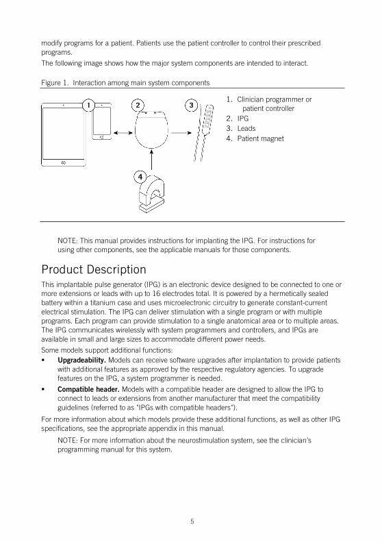
The following image shows how the major system components are intended to interact.
Figure 1. Interaction among main system components
1. Clinician programmer or patient controller
2. IPG 3. Leads 4. Patient magnet
NOTE: This manual provides instructions for implanting the IPG. For instructions for using other components, see the applicable manuals for those components.
Product Description This implantable pulse generator (IPG) is an electronic device designed to be connected to one or more extensions or leads with up to 16 electrodes total. It is powered by a hermetically sealed battery within a titanium case and uses microelectronic circuitry to generate constant-current electrical stimulation. The IPG can deliver stimulation with a single program or with multiple programs. Each program can provide stimulation to a single anatomical area or to multiple areas. The IPG communicates wirelessly with system programmers and controllers, and IPGs are available in small and large sizes to accommodate different power needs.
Some models support additional functions: Upgradeability. Models can receive software upgrades after implantation to provide patients
with additional features as approved by the respective regulatory agencies. To upgrade features on the IPG, a system programmer is needed.
Compatible header. Models with a compatible header are designed to allow the IPG to connect to leads or extensions from another manufacturer that meet the compatibility guidelines (referred to as "IPGs with compatible headers").
For more information about which models provide these additional functions, as well as other IPG specifications, see the appropriate appendix in this manual.
NOTE: For more information about the neurostimulation system, see the clinician’s programming manual for this system.
6
NOTE: In this document, the term "clinician programmer" refers to the St. Jude Medical™ Clinician Programmer device, "patient controller" refers to the St. Jude Medical™ Patient Controller device, "clinician programmer app" refers to the St. Jude Medical™ Clinician Programmer software application (app), and "patient controller app" refers to the St. Jude Medical™ Patient Controller app.
Package Contents In addition to the product documentation, the IPG kit contains the following items: 1 IPG (see the appendix in this manual for model numbers)
1 pocket sizer
1 torque wrench (Model 1101)
2 port plugs (Model 1111)
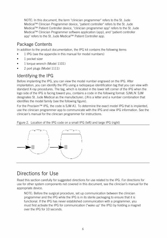
Identifying the IPG Before implanting the IPG, you can view the model number engraved on the IPG. After implantation, you can identify the IPG using a radiopaque identification tag that you can view with standard X-ray procedures. The tag, which is located in the lower left corner of the IPG when the logo side of the IPG is facing toward you, contains a code in the following format: SJMLN. SJM designates St. Jude Medical as the manufacturer; LN is a letter and a number combination that identifies the model family (see the following figure).
For the Proclaim™ IPG, the code is SJM A1. To determine the exact model IPG that is implanted, use the clinician programmer app to communicate with the IPG and view IPG information. See the clinician’s manual for the clinician programmer for instructions.
Figure 2. Location of the IPG code on a small IPG (left) and large IPG (right)
Directions for Use Read this section carefully for suggested directions for use related to the IPG. For directions for use for other system components not covered in this document, see the clinician’s manual for the appropriate device.
NOTE: Before the surgical procedure, set up communication between the clinician programmer and the IPG while the IPG is in its sterile packaging to ensure that it is functional. If the IPG has never established communication with a programmer, you must first activate the IPG for communication ("wake up" the IPG) by holding a magnet over the IPG for 10 seconds.
7
Creating an IPG Pocket The following steps outline the suggested procedure to create an IPG pocket:
1. Determine the site for the IPG, ensuring that the lead is long enough to reach the pocket and provide a strain relief loop.
NOTE: Common sites for IPG implantation are along the midaxillary line, in the upper buttock along the posterior axillary line (taking care to avoid the belt line), and in the area over the abdomen just below the lowermost rib. To ensure a flat area is selected, you can mark a flat area prior to the surgical procedure while the patient is in a sitting position.
CAUTION: Do not place the IPG deeper than 4.0 cm (1.57 in) because the clinician programmer may not communicate effectively with the IPG.
2. Create the pocket so that the IPG is parallel to the skin surface and no deeper than 4.0 cm (1.57 in) below the skin surface.
3. Insert and remove the pocket sizer to ensure that the pocket is large enough to accommodate the IPG, allowing enough extra room for a strain relief loop for each lead or extension.
Connecting a Lead or Extension to the IPG The following steps outline the suggested guidelines to connect a lead or extension to the IPG:
WARNING: To avoid harming the patient or damaging the neurostimulation system, ensure that any electrosurgery procedures are completed before connecting the leads or extensions to the IPG.
CAUTION: Do not connect a lead or extension with body fluid or saline residue on its contacts because corrosion can occur and cause failure of the system.
1. If any of the lead or extension contacts came in contact with body fluid or saline, thoroughly clean the contacts with sterile deionized water or sterile water for irrigation and dry them completely.
CAUTION: Observe these cautions when performing the following step:
Do not bend the lead sharply or it may be damaged. Do not loosen the setscrew in the connector more than a quarter turn at a time
while trying to insert the lead. Retracting the setscrew too far can cause the setscrew to come loose and make the connector assembly unusable.
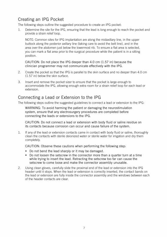
2. Using clean gloves, carefully slide the proximal end of the lead or extension into the IPG header until it stops. When the lead or extension is correctly inserted, the contact bands on the lead or extension are fully inside the connector assembly and the windows between each of the header contacts are clear.
8
Figure 3. Insert the lead or extension fully into the IPG header
1. Fully inserted 2. Not fully inserted 3. Window between each header contact is
clear 4. Window between each header contact is
partially blocked by contact band
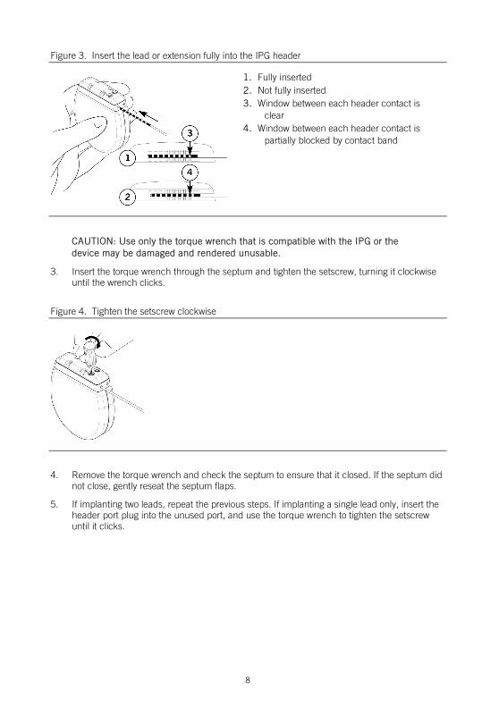
CAUTION: Use only the torque wrench that is compatible with the IPG or the device may be damaged and rendered unusable.
3. Insert the torque wrench through the septum and tighten the setscrew, turning it clockwise until the wrench clicks.
Figure 4. Tighten the setscrew clockwise
4. Remove the torque wrench and check the septum to ensure that it closed. If the septum did not close, gently reseat the septum flaps.
5. If implanting two leads, repeat the previous steps. If implanting a single lead only, insert the header port plug into the unused port, and use the torque wrench to tighten the setscrew until it clicks.

9
Figure 5. Insert the port plug
Implanting the IPG The following steps outline the suggested procedure to implant the IPG:
1. Place the IPG into the IPG pocket with the logo side facing the skin surface and at a depth not to exceed 4.0 cm (1.57 in).
NOTE: By implanting the IPG with the logo side facing the skin surface, you enhance the IPG's ability to detect a magnet.
2. Carefully coil any excess lead or extension behind the IPG in loops no smaller than 2.5 cm (1 in) in diameter to provide strain relief for the lead or extension and IPG connection.
CAUTION: Do not bring the suture needle in contact with an IPG, lead, or extension, or the component may be damaged.
3. To stabilize the IPG within the pocket, pass suture through the holes at the top of the IPG header and secure it to connective tissue.
4. Check the entire system by fluoroscopy before closing to ensure proper positioning of the lead or leads and that it is straight, with no sharp bends or kinks.
5. Use the clinician programmer app to communicate with the IPG and perform intraoperative testing to confirm that the system is operational. See the clinician's manual of the clinician programmer app for instructions.
NOTE: IPG output may not be identical to that of the trial stimulator at the same settings.
6. Ensure that the IPG is away from the pocket incision suture line, close the pocket incision, and apply the appropriate dressings.
Replacing the IPG The following steps outline the suggested procedure to replace an IPG:
1. Turn off stimulation or verify that it is turned off.
CAUTION: Exercise care when using sharp instruments or electrocautery around leads or extensions, or they may be damaged.
2. Open the IPG implant site per normal surgical procedure.
10
3. Insert the torque wrench through the septum of the IPG header and loosen the setscrew by turning it counterclockwise.
CAUTION: When performing the following step, do not bend the lead or extension sharply; or it may be damaged.
4. Gently remove the lead or extension from the IPG header; then clean and dry all connections, ensuring they are free of fluid and tissue.
5. To complete the IPG replacement procedure, see the following sections: “Connecting a Lead or Extension to the IPG” (page 7) and “Implanting the IPG” (page 9).
Disposing of Explanted Components Explanted St. Jude Medical™ components should be returned to St. Jude Medical for proper disposal. To return an explanted component, place it in a container or bag marked with a biohazard label and coordinate the return with your St. Jude Medical representative or Technical Support.
Checking the Status of the IPG Battery The IPG contains a nonrechargeable battery. The amount of time that the battery will provide active stimulation depends on the patient’s stimulation settings and daily usage time. To check the status of the IPG battery, use the clinician programmer app or patient controller app. For more information about this function, refer to the clinician’s programming manual and the user’s guide for the patient controller app. For information about estimating longevity of the IPG battery, see the appropriate appendix in this manual.
NOTE: IPG battery status is available one day after first using the clinician programmer app to program the IPG.
The following list provides general information about the battery status: A low-battery warning will appear on the clinician programmer app or patient controller app
when the battery is approaching its end of service.
Stimulation will automatically stop when the battery cannot support stimulation.
Technical Support For technical questions and support for your product, use the following information: +1 855 478 5833 (toll-free within North America)
+1 651 756 5833
For additional assistance, call your local St. Jude Medical representative.
11
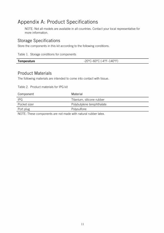
Appendix A: Product Specifications NOTE: Not all models are available in all countries. Contact your local representative for more information.
Storage Specifications Store the components in this kit according to the following conditions.
Table 1. Storage conditions for components
Temperature -20°C–60°C (-4°F–140°F)
Product Materials The following materials are intended to come into contact with tissue.
Table 2. Product materials for IPG kit
Component Material
IPG Titanium, silicone rubber
Pocket sizer Polybutylene terephthalate
Port plug Polysulfone
NOTE: These components are not made with natural rubber latex.
12
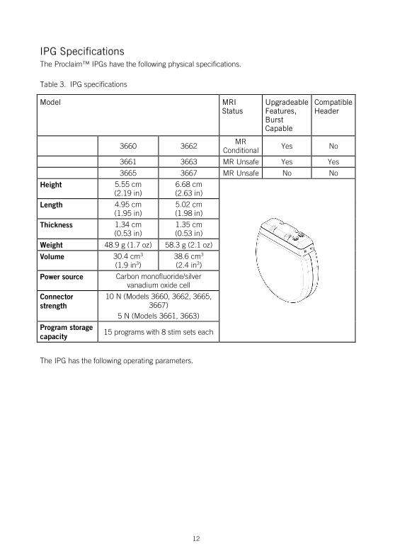
IPG Specifications The Proclaim™ IPGs have the following physical specifications.
Table 3. IPG specifications
Model MRI Status
Upgradeable Features, Burst Capable
Compatible Header
3660 3662
MR Conditional Yes No
3661 3663 MR Unsafe Yes Yes
3665 3667 MR Unsafe No No
Height 5.55 cm (2.19 in)
6.68 cm (2.63 in)
Length 4.95 cm (1.95 in)
5.02 cm (1.98 in)
Thickness 1.34 cm (0.53 in)
1.35 cm (0.53 in)
Weight 48.9 g (1.7 oz) 58.3 g (2.1 oz)
Volume 30.4 cm3 (1.9 in3)
38.6 cm3 (2.4 in3)
Power source Carbon monofluoride/silver vanadium oxide cell
Connector strength
10 N (Models 3660, 3662, 3665, 3667)
5 N (Models 3661, 3663)
Program storage capacity
15 programs with 8 stim sets each
The IPG has the following operating parameters.
13
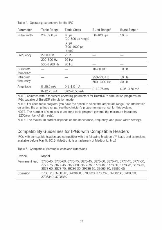
Table 4. Operating parameters for the IPG
Parameter Tonic Range Tonic Steps Burst Range* Burst Steps*
Pulse width 20–1000 µs 10 µs (20–500 µs range) 50 µs (500–1000 µs range)
50–1000 µs 50 µs
Frequency 2–200 Hz 2 Hz — —
200–500 Hz 10 Hz — —
500–1200 Hz 20 Hz — —
Burst rate frequency
— — 10–60 Hz 10 Hz
Intraburst frequency
— — 250–500 Hz 10 Hz
500–1000 Hz 20 Hz
Amplitude 0–25.5 mA 0.1–1.0 mA 0–12.75 mA 0.05–0.50 mA 0–12.75 mA 0.05–0.50 mA
NOTE: Columns with * represent operating parameters for BurstDR™ stimulation programs on IPGs capable of BurstDR stimulation mode. NOTE: For each tonic program, you have the option to select the amplitude range. For information on setting the amplitude range, see the clinician's programming manual for this system. NOTE: The number of stim sets in use for a tonic program governs the maximum frequency (1200/number of stim sets). NOTE: The maximum current depends on the impedance, frequency, and pulse width settings.
Compatibility Guidelines for IPGs with Compatible Headers IPGs with compatible headers are compatible with the following Medtronic™ leads and extensions available before May 5, 2015. (Medtronic is a trademark of Medtronic, Inc.)
Table 5. Compatible Medtronic leads and extensions
Device Model
Permanent lead 3776-45, 3776-60, 3776-75, 3876-45, 3876-60, 3876-75, 3777-45, 3777-60, 3777-75, 3877-45, 3877-60, 3877-75, 3778-45, 3778-60, 3778-75, 3878-45, 3878-60, 3878-75, 39286-30, 39286-65, 39565-30, 39565-65
Extension 3708120, 3708140, 3708160, 3708220, 3708240, 3708260, 3708320, 3708340, 3708360
14
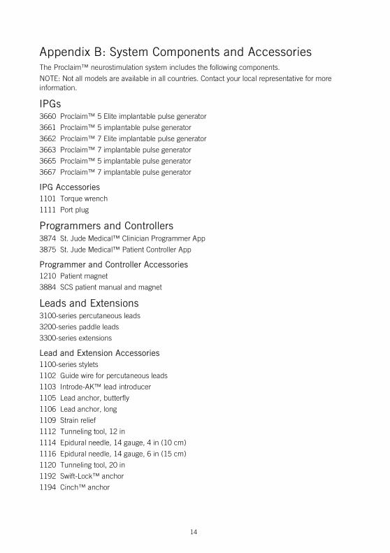
Appendix B: System Components and Accessories The Proclaim™ neurostimulation system includes the following components.
NOTE: Not all models are available in all countries. Contact your local representative for more information.
IPGs 3660 Proclaim™ 5 Elite implantable pulse generator
3661 Proclaim™ 5 implantable pulse generator
3662 Proclaim™ 7 Elite implantable pulse generator
3663 Proclaim™ 7 implantable pulse generator
3665 Proclaim™ 5 implantable pulse generator
3667 Proclaim™ 7 implantable pulse generator
IPG Accessories 1101 Torque wrench
1111 Port plug
Programmers and Controllers 3874 St. Jude Medical™ Clinician Programmer App
3875 St. Jude Medical™ Patient Controller App
Programmer and Controller Accessories 1210 Patient magnet
3884 SCS patient manual and magnet
Leads and Extensions 3100-series percutaneous leads
3200-series paddle leads
3300-series extensions
Lead and Extension Accessories 1100-series stylets
1102 Guide wire for percutaneous leads
1103 Introde-AK™ lead introducer
1105 Lead anchor, butterfly
1106 Lead anchor, long
1109 Strain relief
1112 Tunneling tool, 12 in
1114 Epidural needle, 14 gauge, 4 in (10 cm)
1116 Epidural needle, 14 gauge, 6 in (15 cm)
1120 Tunneling tool, 20 in
1192 Swift-Lock™ anchor
1194 Cinch™ anchor
15
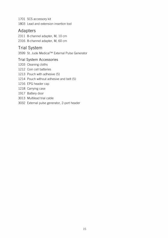
1701 SCS accessory kit
1803 Lead and extension insertion tool
Adapters 2311 8-channel adapter, M, 10 cm
2316 8-channel adapter, M, 60 cm
Trial System 3599 St. Jude Medical™ External Pulse Generator
Trial System Accessories 1203 Cleaning cloths
1212 Coin cell batteries
1213 Pouch with adhesive (5)
1214 Pouch without adhesive and belt (5)
1216 EPG header cap
1218 Carrying case
1917 Battery door
3013 Multilead trial cable
3032 External pulse generator, 2-port header

16
Appendix C: Battery Longevity Information The longevity of the IPG battery depends on the following factors: Programmed settings, such as frequency, pulse width, amplitude, and number of active
electrodes
Program impedance
Hours of stimulation per day
Shelf life of the device between the dates of manufacture and implant
Duration of communication sessions between the IPG and the patient controller or clinician programmer
To estimate battery longevity manually, perform the following steps. For additional help with estimating battery longevity, contact Technical Support.
1. Locate the energy factor for the desired stimulation parameters according to the lead impedance in the tables in one of the following sections:
- For IPGs using tonic stimulation parameters, see "Energy Factors for Tonic Stimulation Parameters" (page 17).
- For IPGs using BurstDR™ stimulation parameters, see "Energy Factors for BurstDR™ Stimulation Parameters" (page 21).
NOTE: If the desired parameters do not appear in the tables, estimate the energy factor by choosing a value between the listed energy factors for the closest parameters.
2. For an IPG using multiple areas, determine the energy factor for each area from the previous step, and add each of these values together.
3. Use the figures in "Battery Longevity Graphs" (page 22) to determine the estimated battery longevity by finding the energy factor from the previous steps on the curve for the appropriate model IPG.
17
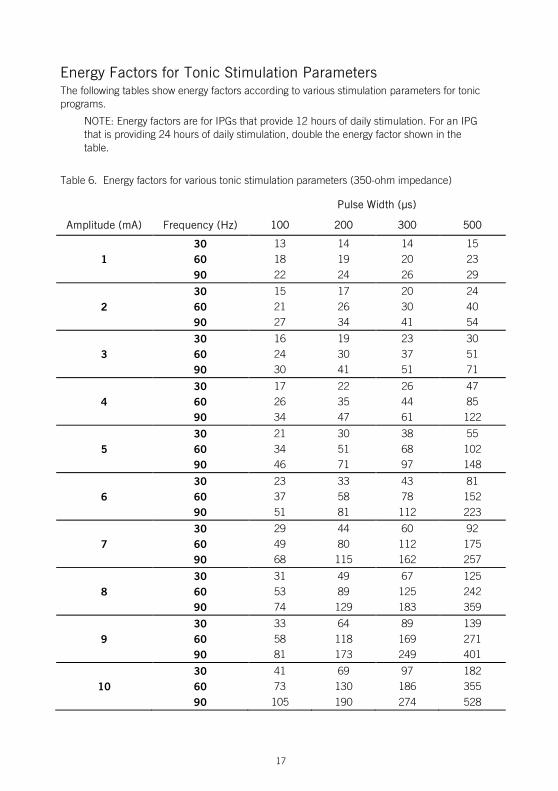
Energy Factors for Tonic Stimulation Parameters The following tables show energy factors according to various stimulation parameters for tonic programs.
NOTE: Energy factors are for IPGs that provide 12 hours of daily stimulation. For an IPG that is providing 24 hours of daily stimulation, double the energy factor shown in the table.
Table 6. Energy factors for various tonic stimulation parameters (350-ohm impedance)
Pulse Width (µs)
Amplitude (mA) Frequency (Hz) 100 200 300 500
30 13 14 14 15
1 60 18 19 20 23 90 22 24 26 29 30 15 17 20 24
2 60 21 26 30 40 90 27 34 41 54 30 16 19 23 30
3 60 24 30 37 51 90 30 41 51 71 30 17 22 26 47
4 60 26 35 44 85 90 34 47 61 122 30 21 30 38 55
5 60 34 51 68 102 90 46 71 97 148 30 23 33 43 81
6 60 37 58 78 152 90 51 81 112 223 30 29 44 60 92
7 60 49 80 112 175 90 68 115 162 257 30 31 49 67 125
8 60 53 89 125 242 90 74 129 183 359 30 33 64 89 139
9 60 58 118 169 271 90 81 173 249 401 30 41 69 97 182
10 60 73 130 186 355 90 105 190 274 528
18
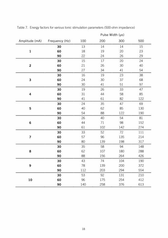
Table 7. Energy factors for various tonic stimulation parameters (500-ohm impedance)
Pulse Width (µs)
Amplitude (mA) Frequency (Hz) 100 200 300 500
30 13 14 14 15
1 60 18 19 20 23 90 22 24 26 29 30 15 17 20 24
2 60 21 26 30 40 90 27 34 41 54 30 16 19 23 38
3 60 24 30 37 68 90 30 41 51 97 30 19 26 33 47
4 60 31 44 58 85 90 41 61 82 122 30 24 35 47 69
5 60 40 62 85 130 90 54 88 122 190 30 26 40 54 81
6 60 44 71 98 152 90 61 102 142 274 30 33 52 72 111
7 60 57 96 135 214 90 80 139 198 317 30 35 58 94 148
8 60 62 107 180 288 90 88 156 264 426 30 43 74 104 190
9 60 78 139 200 372 90 112 203 294 554 30 53 92 131 210
10 60 96 175 254 412 90 140 258 376 613

19
Table 8. Energy factors for various tonic stimulation parameters (700-ohm impedance)
Pulse Width (µs)
Amplitude (mA) Frequency (Hz) 100 200 300 500
30 13 14 16 18
1 60 18 19 24 28 90 22 24 31 38 30 15 17 20 24
2 60 21 26 30 40 90 27 34 41 54 30 18 23 28 38
3 60 27 37 48 68 90 36 51 66 97 30 22 31 40 58
4 60 35 53 71 107 90 47 75 102 156 30 24 41 55 83
5 60 40 73 102 158 90 54 105 148 232 30 30 47 63 114
6 60 51 85 119 220 90 71 122 173 325 30 37 60 84 151
7 60 65 112 159 294 90 92 163 234 436 30 45 76 108 197
8 60 81 144 207 382 90 116 211 305 566 30 58 98 139 220
9 60 103 184 265 427 90 147 269 390 710 30 62 119 169 271
10 60 112 225 326 529 90 160 330 482 871
20
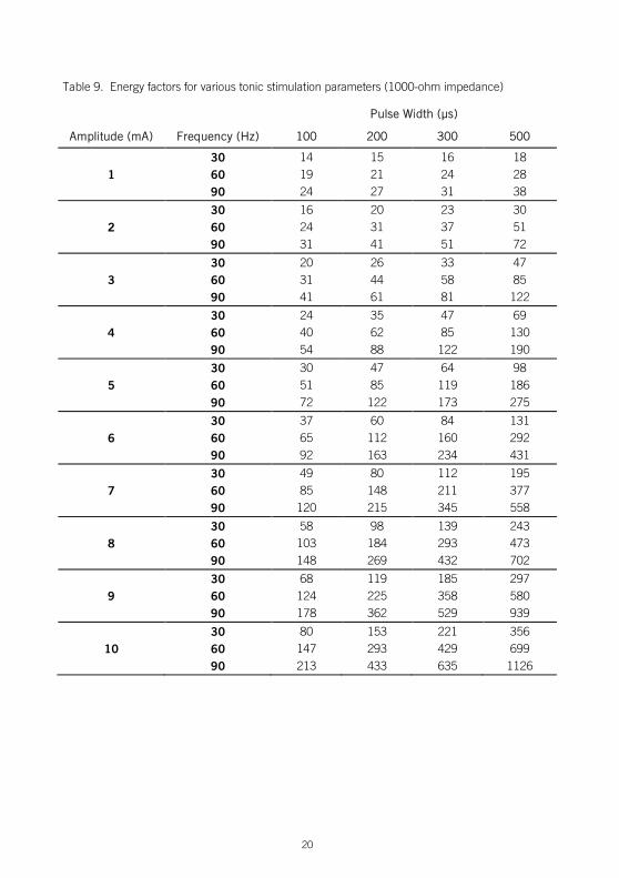
Table 9. Energy factors for various tonic stimulation parameters (1000-ohm impedance)
Pulse Width (µs)
Amplitude (mA) Frequency (Hz) 100 200 300 500
30 14 15 16 18
1 60 19 21 24 28 90 24 27 31 38 30 16 20 23 30
2 60 24 31 37 51 90 31 41 51 72 30 20 26 33 47
3 60 31 44 58 85 90 41 61 81 122 30 24 35 47 69
4 60 40 62 85 130 90 54 88 122 190 30 30 47 64 98
5 60 51 85 119 186 90 72 122 173 275 30 37 60 84 131
6 60 65 112 160 292 90 92 163 234 431 30 49 80 112 195
7 60 85 148 211 377 90 120 215 345 558 30 58 98 139 243
8 60 103 184 293 473 90 148 269 432 702 30 68 119 185 297
9 60 124 225 358 580 90 178 362 529 939 30 80 153 221 356
10 60 147 293 429 699 90 213 433 635 1126
21
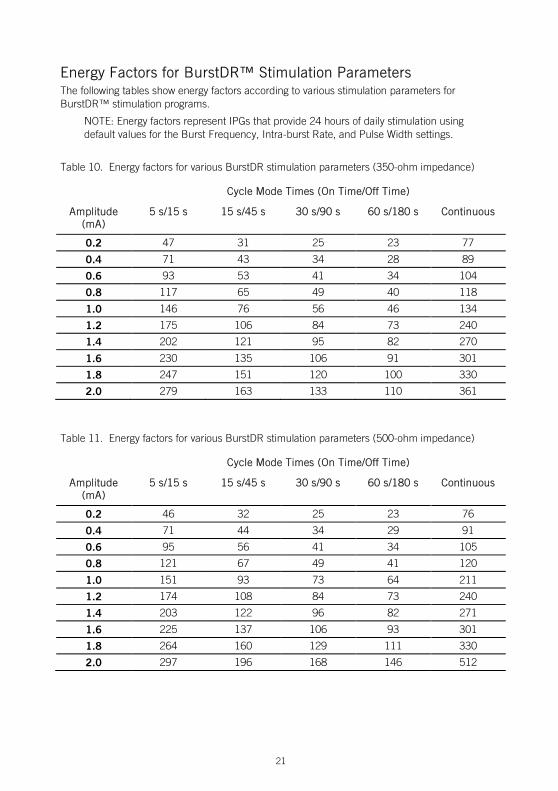
Energy Factors for BurstDR™ Stimulation Parameters The following tables show energy factors according to various stimulation parameters for BurstDR™ stimulation programs.
NOTE: Energy factors represent IPGs that provide 24 hours of daily stimulation using default values for the Burst Frequency, Intra-burst Rate, and Pulse Width settings.
Table 10. Energy factors for various BurstDR stimulation parameters (350-ohm impedance)
Cycle Mode Times (On Time/Off Time)
Amplitude (mA)
5 s/15 s 15 s/45 s 30 s/90 s 60 s/180 s Continuous
0.2 47 31 25 23 77
0.4 71 43 34 28 89
0.6 93 53 41 34 104
0.8 117 65 49 40 118
1.0 146 76 56 46 134
1.2 175 106 84 73 240
1.4 202 121 95 82 270
1.6 230 135 106 91 301
1.8 247 151 120 100 330
2.0 279 163 133 110 361
Table 11. Energy factors for various BurstDR stimulation parameters (500-ohm impedance)
Cycle Mode Times (On Time/Off Time)
Amplitude (mA)
5 s/15 s 15 s/45 s 30 s/90 s 60 s/180 s Continuous
0.2 46 32 25 23 76
0.4 71 44 34 29 91
0.6 95 56 41 34 105
0.8 121 67 49 41 120
1.0 151 93 73 64 211
1.2 174 108 84 73 240
1.4 203 122 96 82 271
1.6 225 137 106 93 301
1.8 264 160 129 111 330
2.0 297 196 168 146 512
22
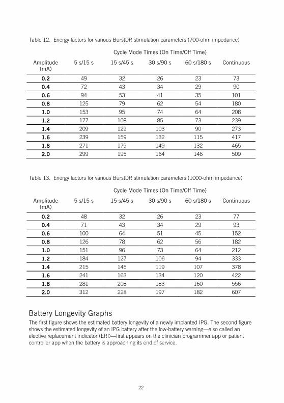
Table 12. Energy factors for various BurstDR stimulation parameters (700-ohm impedance)
Cycle Mode Times (On Time/Off Time)
Amplitude (mA)
5 s/15 s 15 s/45 s 30 s/90 s 60 s/180 s Continuous
0.2 49 32 26 23 73
0.4 72 43 34 29 90
0.6 94 53 41 35 101
0.8 125 79 62 54 180
1.0 153 95 74 64 208
1.2 177 108 85 73 239
1.4 209 129 103 90 273
1.6 239 159 132 115 417
1.8 271 179 149 132 465
2.0 299 195 164 146 509
Table 13. Energy factors for various BurstDR stimulation parameters (1000-ohm impedance)
Cycle Mode Times (On Time/Off Time)
Amplitude (mA)
5 s/15 s 15 s/45 s 30 s/90 s 60 s/180 s Continuous
0.2 48 32 26 23 77
0.4 71 43 34 29 93
0.6 100 64 51 45 152
0.8 126 78 62 56 182
1.0 151 96 73 64 212
1.2 184 127 106 94 333
1.4 215 145 119 107 378
1.6 241 163 134 120 422
1.8 281 208 183 160 556
2.0 312 228 197 182 607
Battery Longevity Graphs The first figure shows the estimated battery longevity of a newly implanted IPG. The second figure shows the estimated longevity of an IPG battery after the low-battery warning—also called an elective replacement indicator (ERI)—first appears on the clinician programmer app or patient controller app when the battery is approaching its end of service.
23
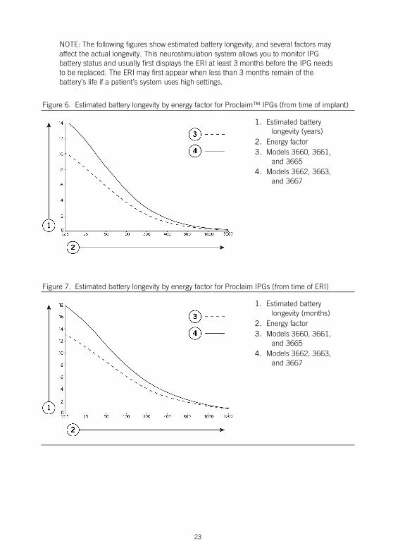
NOTE: The following figures show estimated battery longevity, and several factors may affect the actual longevity. This neurostimulation system allows you to monitor IPG battery status and usually first displays the ERI at least 3 months before the IPG needs to be replaced. The ERI may first appear when less than 3 months remain of the battery’s life if a patient’s system uses high settings.
Figure 6. Estimated battery longevity by energy factor for Proclaim™ IPGs (from time of implant)
1. Estimated battery longevity (years)
2. Energy factor 3. Models 3660, 3661,
and 3665 4. Models 3662, 3663,
and 3667
Figure 7. Estimated battery longevity by energy factor for Proclaim IPGs (from time of ERI)
1. Estimated battery longevity (months)
2. Energy factor 3. Models 3660, 3661,
and 3665 4. Models 3662, 3663,
and 3667
24
Appendix D: Regulatory Statements This section contains regulatory statements about your product.
Disposal Guidelines for Battery-Powered Devices This device contains a battery and a label is affixed to the device in accordance with European Council directives 2002/96/EC and 2006/66/EC. These directives call for separate collection and disposal of electrical and electronic equipment and batteries. Sorting such waste and removing it from other forms of waste lessens the contribution of potentially toxic substances into municipal disposal systems and into the larger ecosystem. Return the device to St. Jude Medical at the end of its operating life.
Statement of FCC Compliance This equipment has been tested and found to comply with the limits for a Class B digital device, pursuant to part 15 of the FCC rules. These limits are designed to provide reasonable protection against harmful interference in a residential installation. This equipment generates, uses, and can radiate radiofrequency energy and, if not installed and used in accordance with the instructions, may cause harmful interference to radio communications. However, there is no guarantee that interference will not occur in a particular installation. If this equipment does cause harmful interference to radio or television reception, which can be determined by turning the equipment off and on, the user is encouraged to try to correct the interference by one or more of the following measures: Reorient or relocate the receiving antenna.
Increase the separation between the equipment and receiver.
Connect the equipment into an outlet on a circuit different from that to which the receiver is connected.
Consult the dealer or an experienced radio/TV technician for help.
Operation is subject to the following two conditions: This device may not cause harmful interference.
This device must accept any interference received, including interference that may cause undesired operation.
Modifications not expressly approved by the manufacturer could void the user’s authority to operate the equipment under FCC rules.
Statement of Compliance With License-Exempt RSS Standard (Canada) This device complies with Industry Canada license-exempt RSS standard(s). Operation is subject to the following two conditions: (1) this device may not cause interference, and (2) this device must accept any interference, including interference that may cause undesired operation of the device.
25
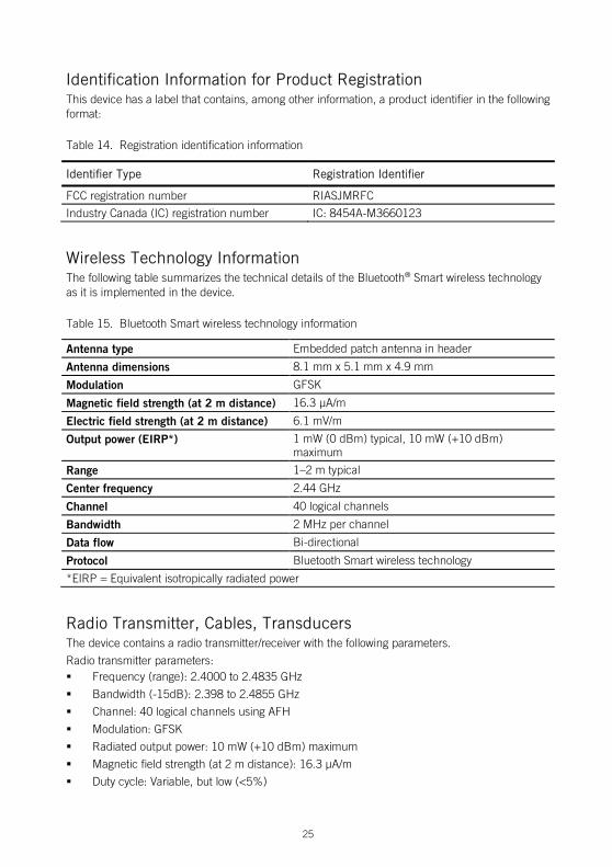
Identification Information for Product Registration This device has a label that contains, among other information, a product identifier in the following format:
Table 14. Registration identification information
Identifier Type Registration Identifier
FCC registration number RIASJMRFC
Industry Canada (IC) registration number IC: 8454A-M3660123
Wireless Technology Information The following table summarizes the technical details of the Bluetooth® Smart wireless technology as it is implemented in the device.
Table 15. Bluetooth Smart wireless technology information
Antenna type Embedded patch antenna in header
Antenna dimensions 8.1 mm x 5.1 mm x 4.9 mm
Modulation GFSK
Magnetic field strength (at 2 m distance) 16.3 µA/m
Electric field strength (at 2 m distance) 6.1 mV/m
Output power (EIRP*) 1 mW (0 dBm) typical, 10 mW (+10 dBm) maximum
Range 1–2 m typical
Center frequency 2.44 GHz
Channel 40 logical channels
Bandwidth 2 MHz per channel
Data flow Bi-directional
Protocol Bluetooth Smart wireless technology
*EIRP = Equivalent isotropically radiated power
Radio Transmitter, Cables, Transducers The device contains a radio transmitter/receiver with the following parameters.
Radio transmitter parameters: Frequency (range): 2.4000 to 2.4835 GHz
Bandwidth (-15dB): 2.398 to 2.4855 GHz
Channel: 40 logical channels using AFH
Modulation: GFSK
Radiated output power: 10 mW (+10 dBm) maximum
Magnetic field strength (at 2 m distance): 16.3 µA/m
Duty cycle: Variable, but low (<5%)
26
Semi-duplex capability
The radio receiver in the device is using the same frequency and bandwidth as the transmitter.
Cables and transducers:
Cables and transducers are not used during normal use of the device nor while programming the device.
Quality of Service for Wireless Technology Bluetooth® Smart wireless technology enables communication between the generator and the clinician programmer or patient controller. The quality of the wireless communication link varies depending on the use environment (operating room, recovery room, and home environment).
After the clinician programmer or patient controller is paired with a generator, the Bluetooth wireless technology symbol is visible on the clinician programmer or patient controller in the upper right-hand corner of the screen. When the Bluetooth Smart wireless technology connection is not active, the symbol appears dimmed.
The quality of service (QoS) should allow wireless data to be transferred at a net rate of 2.5 kB/sec. Each connection interval includes a semi-duplex transmission with a required acknowledge, a transmission latency in each direction (2x), and a receive-to-transmit mode (RX-to-TX) time. Data is resent if not successfully received. Each key press may transmit up to 4 data packets with up to 20 bytes per packet, depending on the number of packets that need to be transmitted (i.e., if there is only one packet to transmit, only one packet will be transmitted). If the interference is high (e.g., the bit error rate exceeds 0.1%), the user may experience what appears to be a slow connection, difficulty pairing devices, and a need to decrease the distance between connected devices. For information on how to improve connection issues, please refer to “Troubleshooting for Wireless and Coexistence Issues” (page 26).
Wireless Security Measures The wireless signals are secured through device system design that includes the following: The generator will encrypt its wireless communication.
Only one patient controller or clinician programmer may communicate with the generator at the same time.
A unique key for each unit that is checked during each transmission.
Built-in pairing that specifies valid and legitimate pairing among units.
Proprietary authentication in addition to the pairing procedure specified in Bluetooth® Smart wireless technology, which includes an element of proximity.
A proprietary algorithm that detects and prevents an unauthorized user from attempting to pair with the generator.
Troubleshooting for Wireless and Coexistence Issues If you experience issues with the wireless communication between the generator and the clinician programmer or patient controller, try the following: Decrease the distance between the devices
Move the devices so they share line of sight
27
Move the devices away from other devices that may be causing interference
Close the clinician programmer or patient controller application, and turn the clinician programmer or patient controller off and on
Wait a few minutes and try connecting again
Do not operate other wireless devices (i.e., laptop, tablet, mobile phone, or cordless phone) at the same time
NOTE: Wireless communications equipment, such as wireless home network devices, mobile and cordless telephones, and tablets, can affect the device.
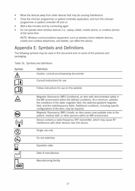
Appendix E: Symbols and Definitions The following symbols may be used in this document and on some of the products and packaging:
Table 16. Symbols and definitions
Symbol Definition
Caution, consult accompanying documents
Consult instructions for use
Follow instructions for use on this website
Magnetic Resonance (MR) Conditional, an item with demonstrated safety in the MR environment within the defined conditions. At a minimum, address the conditions of the static magnetic field, the switched gradient magnetic field, and the radiofrequency fields. Additional conditions, including specific configurations of the item, may be required.
Magnetic Resonance (MR) Unsafe, an item poses unacceptable risks to the patient, medical staff, or other persons within an MR environment
Device contains a radio-frequency (RF) transmitter, which may cause RF interference with other devices near this device.
Single use only
Do not resterilize
Expiration date
Date of manufacture
Manufacturing facility
28
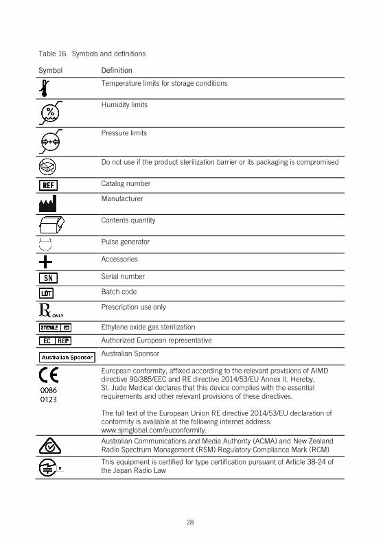
Table 16. Symbols and definitions
Symbol Definition
Temperature limits for storage conditions
Humidity limits
Pressure limits
Do not use if the product sterilization barrier or its packaging is compromised
Catalog number
Manufacturer
Contents quantity
Pulse generator
Accessories
Serial number
Batch code
Prescription use only
Ethylene oxide gas sterilization
Authorized European representative
Australian Sponsor
European conformity, affixed according to the relevant provisions of AIMD directive 90/385/EEC and RE directive 2014/53/EU Annex II. Hereby, St. Jude Medical declares that this device complies with the essential requirements and other relevant provisions of these directives. The full text of the European Union RE directive 2014/53/EU declaration of conformity is available at the following internet address: www.sjmglobal.com/euconformity.
Australian Communications and Media Authority (ACMA) and New Zealand Radio Spectrum Management (RSM) Regulatory Compliance Mark (RCM)
This equipment is certified for type certification pursuant of Article 38-24 of the Japan Radio Law
29
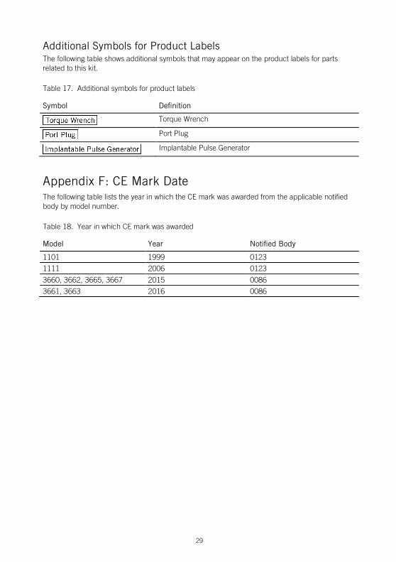
Additional Symbols for Product Labels The following table shows additional symbols that may appear on the product labels for parts related to this kit.
Table 17. Additional symbols for product labels
Symbol Definition
Torque Wrench
Port Plug
Implantable Pulse Generator
Appendix F: CE Mark Date The following table lists the year in which the CE mark was awarded from the applicable notified body by model number.
Table 18. Year in which CE mark was awarded
Model Year Notified Body
1101 1999 0123
1111 2006 0123
3660, 3662, 3665, 3667 2015 0086
3661, 3663 2016 0086


St. Jude Medical 6901 Preston Road Plano, Texas 75024 USA +1 855 478 5833 +1 651 756 5833
St. Jude Medical Coordination Center BVBA The Corporate Village Da Vincilaan 11 Box F1 1935 Zaventem Belgium +32 2 774 68 11
St. Jude Medical Australia Pty. Limited 17 Orion Road Lane Cove NSW 2066 Australia
St. Jude Medical Puerto Rico LLC Lot A Interior - #2 Rd Km. 67.5 Santana Industrial Park Arecibo, PR 00612 USA
St. Jude Medical Operations (M) Sdn. Bhd. Plot 102, Lebuhraya Kampung Jawa, Bayan Lepas Industrial Zone 11900 Penang Malaysia
sjm.com
2017-11 ARTEN600017308 A
*600017308*