Embed Size (px)
Citation preview

Manufactured by Bioness Neuromodulation Ltd.A Bioness Inc Company19 Ha’Haroshet StreetPO Box 2500Industrial ZoneRa’Anana 43654, Israel
Worldwide Corporate OfficeBioness Inc25103 Rye Canyon LoopValencia, CA 91355 USATelephone: 800.211.9136Email: [email protected]: www.bioness.com
602-00503-001 Rev. C
NESS®, NESS H200®, NESS H200® Wireless, Bioness, the Bioness Logo®, and LiveOn® are trademarks of Bioness Inc. | www.bioness.com
Rx Only
©2011 Bioness Inc.
Clinician’s Guide
Clinician’s Guide
Rx Only
II Clinician's Guide
Clinician’s Guide Copyright© 2011, Bioness Inc
All Rights ReservedNo part of this publication may be reproduced, transmitted, transcribed, stored in a retrieval system, or translated into any language or any computer language, in any form or by any third party, without the prior written permission of Bioness Inc.
TrademarksNESS®, NESS H200®, NESS H200® Wireless, Bioness, the Bioness Logo® and LiveOn® are trademarks of Bioness Inc. | www.bioness.com | Rx Only
Patents PendingAspects of this device are covered by several patents and patent applications.
DisclaimerBioness Inc and its affiliates shall not be liable for any injury or damage suffered by any person, either directly or indirectly, as a result of the unauthorized use or repair of Bioness Inc products. Bioness Inc and its affiliates do not accept any responsibility for any damage caused to its products, either directly or indirectly, as a result of use and/or repair by unauthorized personnel.
Environmental PolicyService personnel are advised that when changing any part of the NESS H200 Wireless System, care should be taken to dispose of those parts in the correct manner; where applicable, parts should be recycled. When the life cycle of the NESS H200 Wireless System has been completed, the product should be discarded according to the laws and regulations of the local authority. For more detailed information regarding these recommended procedures, please contact Bioness Inc. Bioness Inc is committed to continuously seeking and implementing the best possible manufacturing procedures and servicing routines.
Worldwide Corporate OfficeBioness Inc25103 Rye Canyon Loop Valencia, CA 91355 USATelephone: 800-211-9136 Email: [email protected]: www.bioness.com
Manufactured by Bioness Neuromodulation Ltd. A Bioness Inc Company19 Ha’Haroshet StreetPO Box 2500Industrial ZoneRa’Anana 43654, Israel
Bioness Client Relations Department: Telephone: (800) 211-9136, Option 3; or (661) 362-4850, Option 3.
III
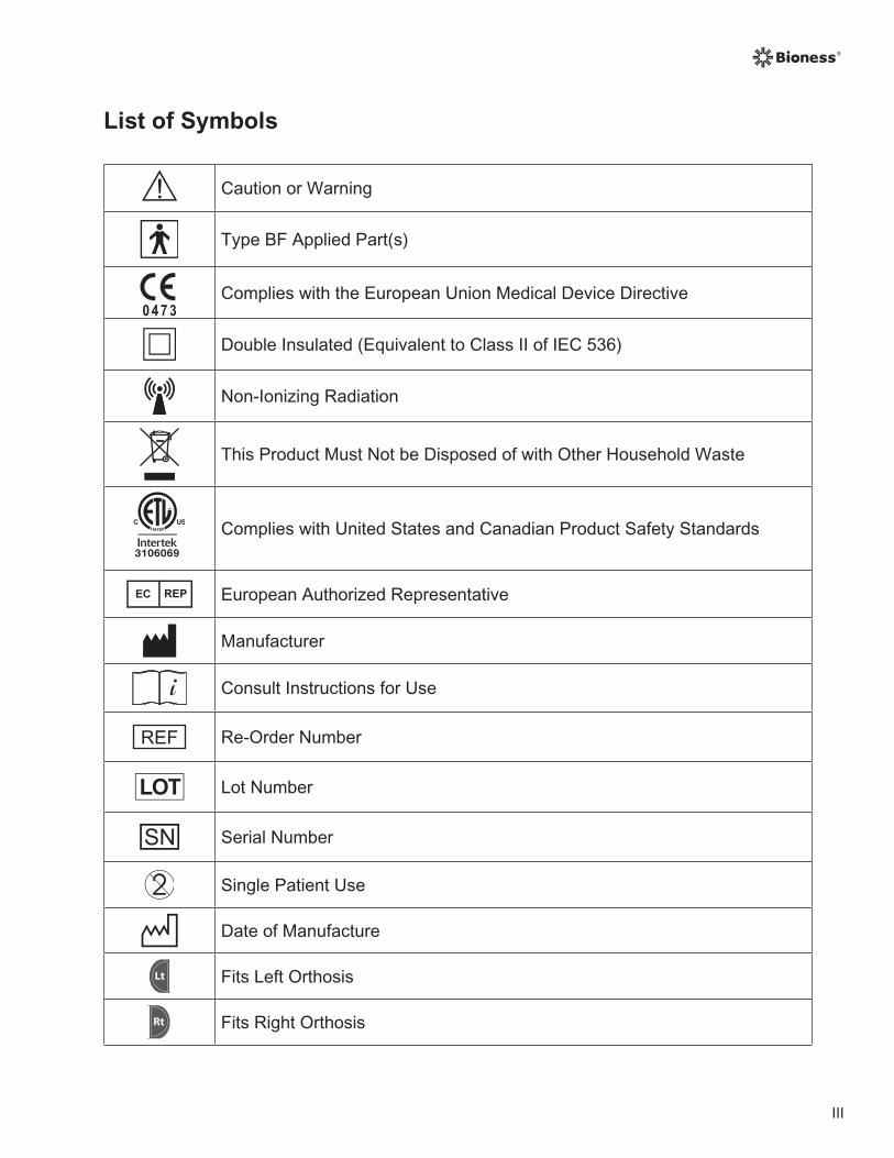
List of Symbols
Caution or Warning
Type BF Applied Part(s)
Complies with the European Union Medical Device Directive
Double Insulated (Equivalent to Class II of IEC 536)
Non-Ionizing Radiation
This Product Must Not be Disposed of with Other Household Waste
Complies with United States and Canadian Product Safety Standards
European Authorized Representative
Manufacturer
Consult Instructions for Use
Re-Order Number
Lot Number
Serial Number
Single Patient Use
Date of Manufacture
Lt Fits Left Orthosis
Rt Fits Right Orthosis
IV Clinician's Guide
Rt
Fits Large Orthosis
Lt
Fits Small and Medium Orthoses
Lt Thick Wrist Insert
RtLarge Thenar
Lt
FPL Panel

V
Table of Contents
List of Symbols ............................................................................................................................................ III
Chapter 1: Introduction ........................................................................................................ 1
Chapter 2: Device Description and Safety Information ........................................................ 3
Device Description ........................................................................................................................................3
Indications for Use ........................................................................................................................................4
Contraindications ..........................................................................................................................................4
Warnings ......................................................................................................................................................4
Adverse Reactions .......................................................................................................................................5
Precautions ...................................................................................................................................................5
Chapter 3: Environmental Conditions that Affect Use .......................................................... 9
Radio Frequency (RF) Communication ........................................................................................................9
Travel and Airport Security .........................................................................................................................10
Electromagnetic Compatibility ....................................................................................................................10
Warnings and Cautions ........................................................................................................................ 11
Chapter 4: The NESS H200 Wireless System ...................................................................... 13
H200 Wireless Orthosis ..............................................................................................................................13
Stimulating Electrodes .........................................................................................................................14
Orthosis Flexor Support .......................................................................................................................15
Orthosis Extensor Wing .......................................................................................................................15
Spiral End of the Orthosis ....................................................................................................................16
Indicator Lights .....................................................................................................................................17
Audio Alerts ..........................................................................................................................................18
Rechargeable Battery and Charging Port ............................................................................................19
H200 Wireless Control Unit ........................................................................................................................20
Operating Buttons ................................................................................................................................20
On/Off Lights ........................................................................................................................................22
Operating Modes .................................................................................................................................22
Standby Mode .........................................................................................................................22
User Mode...............................................................................................................................22
Clinical Mode...........................................................................................................................22
Indicators and Digital Display ...............................................................................................................23
Audio Alerts ..........................................................................................................................................26
Rechargeable Battery and Charging Port ............................................................................................27
VI Clinician's Guide
H200 Wireless Clinical Programs ...............................................................................................................28
Functional Training Programs ..............................................................................................................28
Program A—Grasp and Release ............................................................................................28
Program B—Open Hand .........................................................................................................28
Program C—Grasp .................................................................................................................28
Neuroprosthesis Programs ..................................................................................................................29
Program D—Open Hand .........................................................................................................29
Program E—Grasp and Release ............................................................................................29
Program F—Key Grip..............................................................................................................29
Motor Neuromodulation Program .........................................................................................................29
Program G—Extensors and Flexors, Extensors Only, Flexors Only .......................................29
Personal Preset Programs ...................................................................................................................30
Personal Custom Programming ...........................................................................................................30
Operating the NESS H200 Wireless System ..............................................................................................31
Turning the System On/Off ..................................................................................................................31
Testing Stimulation in the H200 Wireless Orthosis ..............................................................................31
Selecting a User Program ....................................................................................................................31
Entering Clinical Mode .........................................................................................................................31
Selecting a Clinical Program ................................................................................................................31
Turning On Stimulation ........................................................................................................................32
Pausing Stimulation .............................................................................................................................32
Turning Off Stimulation ........................................................................................................................32
Adjusting Stimulation Intensity .............................................................................................................32
Muting/Un-Muting the System Audio Alerts ..........................................................................................32
Entering and Exiting Deep Sleep Mode ...............................................................................................32
Chapter 5: NESS H200 Wireless Clinician’s Kit .................................................................. 33
H200 Wireless Clinician’s Kit (small/medium) ............................................................................................33
H200 Wireless Clinician’s Kit (large) ..........................................................................................................34
H200 Wireless Clinician’s Upgrade Kit (small/medium) .............................................................................34
H200 Wireless Clinician’s Upgrade Kit (large) ............................................................................................35
PDA Components .......................................................................................................................................37
HP iPAQ Clinician’s Programmer with NESS H200 Wireless Software ...............................................37
On/Off Button ..........................................................................................................................38
Charge Indicator Light .............................................................................................................38
VII
SD (Secure Digital) Slot ..........................................................................................................38
Connector Port ........................................................................................................................38
HP iPAQ Configuration Cradle with Stylus ...........................................................................................38
HP iPAQ Clinician’s Programmer Charger ...........................................................................................38
Accessories ................................................................................................................................................39
Thenar ..................................................................................................................................................39
Thenar Screws .....................................................................................................................................39
Wrist Insert ...........................................................................................................................................40
Wrist Insert Screws ..............................................................................................................................40
Wrist Insert Covers ...............................................................................................................................40
H200 Wireless FPL Panel ....................................................................................................................41
H200 Wireless FPL Panel Screws .......................................................................................................41
Fitting Panels .......................................................................................................................................42
Extensor Fitting Panels ...........................................................................................................42
Flexor Fitting Panels ...............................................................................................................43
Electrode Base Set ..............................................................................................................................44
Electrode Base Screw and Washer Set ...............................................................................................44
H200 Wireless Cloth Electrodes ..........................................................................................................44
Chapter 6: Fitting the H200 Wireless Orthosis ................................................................... 45
Measuring for Orthosis Size .......................................................................................................................45
Fitting the Thenar .......................................................................................................................................46
Fitting the Wrist Insert .................................................................................................................................48
Fitting the Wrist Strap and FPL Panel ........................................................................................................51
Attaching the Wrist Strap .....................................................................................................................53
Attaching the FPL Panel ......................................................................................................................55
Determining the Optimal Electrode Configuration ......................................................................................57
Extensor Fitting Panels ........................................................................................................................57
Flexor Fitting Panels ............................................................................................................................59
Wetting/Attaching the H200 Wireless Cloth Electrodes ..............................................................................61
Chapter 7: PDA Setup ......................................................................................................... 63
Connecting the Clinician’s Programmer to the Cradle ................................................................................63
Charging the Clinician’s Programmer .........................................................................................................63
Connecting the H200 Wireless Control Unit ...............................................................................................64
Chapter 8: NESS H200 Wireless Software .......................................................................... 65
VIII Clinician's Guide
Navigation Tools .........................................................................................................................................65
Information Icon ...................................................................................................................................65
Menus ..................................................................................................................................................66
Tabs .....................................................................................................................................................67
Buttons .................................................................................................................................................68
Keyboard ..............................................................................................................................................69
Drop-Down Lists ..................................................................................................................................69
Scroll Bars ............................................................................................................................................70
Stimulation Intensity Bar ......................................................................................................................70
Program Countdown Clock ..................................................................................................................71
Program Active Phase Color Display ...................................................................................................71
Programming the NESS H200 Wireless System ........................................................................................72
Logging In ............................................................................................................................................72
Start-Up Messages ..............................................................................................................................73
New Patient Detected .............................................................................................................73
Control Unit Unassigned .........................................................................................................74
H200 Wireless Control Unit Not Registered ............................................................................74
Data Inconsistency ..................................................................................................................75
Opening/Creating a Patient Record .....................................................................................................76
Configuring Stimulation Parameters ....................................................................................................77
Configuring Clinical Programs A–G .....................................................................................................78
Program A—Grasp & Release ................................................................................................79
Program B—Open Hand .........................................................................................................80
Program C—Grasp .................................................................................................................81
Program D—Grasp & Release ................................................................................................82
Program E—Open Hand .........................................................................................................83
Program F—Key Grip..............................................................................................................84
Program G—Motor Neuromodulation .....................................................................................85
Ext. and Flex. (Extensors and Flexors) ......................................................................85
Extensors ...................................................................................................................86
Flexors .......................................................................................................................87
Configuring a Personal Custom Program ............................................................................................88
Assigning User Program Buttons 1 and 2 ............................................................................................90
IX
Viewing a Patient’s Session Log ................................................................................................................92
Viewing a Patient's Use Log .......................................................................................................................94
Viewing the System Information .................................................................................................................95
Managing Patient Records .........................................................................................................................96
Modifying a Patient Name ....................................................................................................................96
Removing a Patient Record .................................................................................................................96
Managing Users .........................................................................................................................................97
Adding a User ......................................................................................................................................97
Removing a User .................................................................................................................................98
Changing a User’s Password ...............................................................................................................98
Backing Up and Restoring the Database ...................................................................................................99
Automatic Backup ................................................................................................................................99
Manual Backup ....................................................................................................................................99
Restore ..............................................................................................................................................100
Chapter 9: Patient Training and Follow-Up ....................................................................... 101
Patient Training .........................................................................................................................................101
Donning/Doffing the H200 Wireless Orthosis ....................................................................................102
Operating the NESS H200 Wireless System .....................................................................................103
Maintaining and Cleaning the NESS H200 Wireless System ............................................................103
Troubleshooting .................................................................................................................................103
Practicing with the NESS H200 Wireless System ..............................................................................103
Patient Follow-Up and Clinical Support ...................................................................................................104
Suggested Follow-up Agenda ............................................................................................................104
Chapter 10: Maintenance and Cleaning ............................................................................ 105
Charging ...................................................................................................................................................105
Batteries ...................................................................................................................................................105
HP iPAQ Clinician’s Programmer .......................................................................................................105
H200 Wireless Orthosis .....................................................................................................................105
H200 Wireless Control Unit ................................................................................................................105
H200 Wireless Cloth Electrodes ...............................................................................................................106
Electrode Bases .......................................................................................................................................106
Electronic Registration ..............................................................................................................................106
Maintenance Summary .............................................................................................................................107
X Clinician's Guide
Cleaning the H200 Wireless Components ................................................................................................108
Disinfecting the H200 Wireless Components ...........................................................................................108
Electronic Components ......................................................................................................................108
Wrist Insert .........................................................................................................................................109
Chapter 11: Troubleshooting ............................................................................................111
Frequently Asked Questions ..................................................................................................................... 112
Chapter 12: Technical Specifications ............................................................................... 115
Chapter 13: Appendix - EMI Tables ................................................................................... 119
1Chapter 1 - Introduction
1Chapter
Introduction
Stroke and other disorders of the central nervous system (CNS) may cause long-term disability. For many people, long-term disability may impair muscle control, increase muscle spasm, reduce muscle strength, and reduce functional abilities. When the upper limb is involved, complications may include contractures, edema, pain syndromes of the hand and shoulder, and limb-neglect due to learned non-use.
The NESS H200 Wireless Hand Rehabilitation System delivers electrical stimulation to the nerves of the flexor and extensor muscles that control the hand, to improve hand function and treat upper limb impairments resulting from injury to the central nervous system. The NESS H200 Wireless System is easy to operate independently, and promotes clinical efficacy and patient compliance.
This NESS H200 Wireless Clinician’s Guide describes:
• The NESS H200 Wireless System.
• The NESS H200 Wireless Software.
• How to fit the NESS H200 Wireless System.
• How to program the NESS H200 Wireless System.
This guide also includes important safety instructions. Be sure to review the safety instructions with patients before they use the NESS H200 Wireless System.
If you have any questions, please call the Bioness Client Relations Department at (800) 211-9136, Option 3, or visit the Bioness website: www.bioness.com.

2 Clinician's Guide
3Chapter 2 - Device Description and Safety Information
2Chapter
Device Description and Safety Information
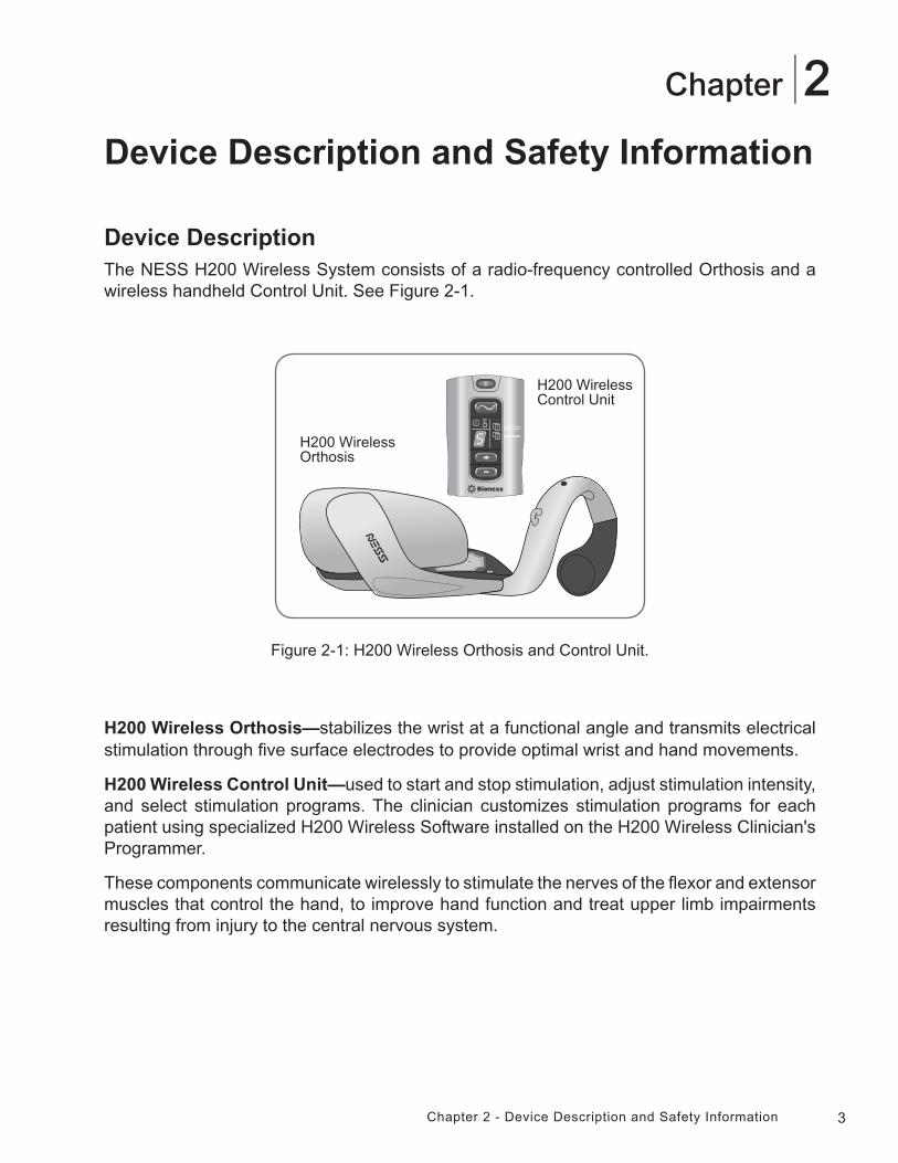
Device DescriptionThe NESS H200 Wireless System consists of a radio-frequency controlled Orthosis and a wireless handheld Control Unit. See Figure 2-1.
Figure 2-1: H200 Wireless Orthosis and Control Unit.
H200 Wireless Orthosis
H200 Wireless Control Unit
H200 Wireless Orthosis—stabilizes the wrist at a functional angle and transmits electrical stimulation through five surface electrodes to provide optimal wrist and hand movements.
H200 Wireless Control Unit—used to start and stop stimulation, adjust stimulation intensity, and select stimulation programs. The clinician customizes stimulation programs for each patient using specialized H200 Wireless Software installed on the H200 Wireless Clinician's Programmer.
These components communicate wirelessly to stimulate the nerves of the flexor and extensor muscles that control the hand, to improve hand function and treat upper limb impairments resulting from injury to the central nervous system.
4 Clinician's Guide
Indications for Use
The NESS H200 Wireless System is an electrical stimulation device indicated for the following uses:
• Functional Electrical Stimulation (FES).
• Improvement of hand function and active range of motion in patients with hemiplegia due to stroke or upper limb paralysis due to C5 spinal cord injury.
• NeuroMuscular Electrical Stimulation (NMES).
• Maintenance and/or increase of hand range of motion.
• Prevention and/or retardation of disuse atrophy.
• Increase in local blood circulation.
• Reduction of muscle spasm.
• Re-education of muscles.
Contraindications
• Do not use the NESS H200 Wireless System on an arm where a cancerous lesion is present or suspected.
• Do not use the NESS H200 Wireless System on patients who have a cardiac pacemaker, implanted defibrillator, or other implanted metallic or electronic device. Use of the NESS H200 Wireless System in conjunction with any of the above may cause electric shock, burns, electrical interference, or death.
• Do not use the NESS H200 Wireless System on an arm where a regional disorder, such as a fracture or dislocation, would be adversely affected by motion from the stimulation.
Warnings
• The H200 Wireless Orthosis is to be worn only on the forearm and hand of the patient for whom it is fitted. It should not be worn by anyone else or on any other part of the body.
• The H200 Wireless Orthosis should not be worn over swollen, infected, or inflamed areas or skin eruptions such as phlebitis, thrombophlebitis, and varicose veins.
• Stimulation should only be applied to normal, intact, clean, healthy skin.
• Advise patients to turn off the NESS H200 Wireless System before driving, operating machinery, or performing any activity in which involuntary muscle contractions may put them at undue risk of injury.
• Advise patients not to use the NESS H200 Wireless System while sleeping.
5Chapter 2 - Device Description and Safety Information
• The NESS H200 Wireless System should only be configured by an authorized clinician.
• Only trained clinicians should determine electrode placement and stimulation settings.
• The H200 Wireless Clinician’s Programmer should only contain the Windows Mobile for Pocket PC operating system and Bioness Inc proprietary software. Third-party software packages are not supported and may interfere with proper operation of the NESS H200 Wireless System, thus voiding the warranty.
• Do not attempt to repair or modify the NESS H200 Wireless System.
• If the H200 Wireless Orthosis overheats, turn off stimulation and remove the Orthosis.
• If stimulation cannot be turned off using the H200 Wireless Control Unit or the trigger button on the H200 Wireless Orthosis, remove the Orthosis to stop stimulation.
• Electrical and wireless medical equipment need special precautions for electromagnetic compatibility and immunity. See Chapter 3 and the Appendix for more information.
Adverse Reactions
• In the unlikely event that any of the following occurs, advise patients to stop using the NESS H200 Wireless System immediately and to consult their physician:
• Signs of significant irritation or pressure sores where the H200 Wireless Orthosis contacts the skin.
• A significant increase in muscle spasticity.
• A feeling of heart-related stress during stimulation.
• Swelling of the hand, wrist, or forearm.
• Any other unanticipated reaction.
• Skin irritations and burns beneath the stimulating electrodes have been reported with the use of powered muscle stimulators.
Precautions
• The long-term effects of chronic electrical stimulation are unknown.
• Use caution with patients who have suspected or diagnosed heart problems. Consult with the patient’s physician before using the NESS H200 Wireless System. The NESS H200 Wireless System may cause lethal rhythm disturbances to the heart in susceptible individuals.
• Any noxious stimulation can trigger autonomic dysreflexia in patients with spinal cord injury at the T6 level and above (acute hypertension and bradycardia).
6 Clinician's Guide
• Use caution with patients who have suspected or diagnosed epilepsy.
• Obtain specific physician clearance before using the NESS H200 Wireless System on patients who have an alteration of normal arterial or venous flow in the region of the H200 Wireless Orthosis because of local insufficiency, occlusion, arteriovenous fistula for the purpose of hemodialysis, or a primary disorder of the vasculature.
• Obtain specific physician clearance before using the NESS H200 Wireless System when patients have a structural deformity in the area to be stimulated.
• The safe use of the NESS H200 Wireless System during pregnancy has not been established.
• Keep the NESS H200 Wireless System out of the reach of children. Advise patients to use the H200 Wireless Orthosis with caution:
• If the patient has a tendency to hemorrhage following acute trauma or fracture.
• Following recent surgical procedures when muscle contraction may disrupt the healing process.
• Over areas of the skin that lack normal sensation.
• Inflammation in the region of the H200 Wireless Orthosis may be aggravated by motion, muscle activity, or pressure from the Orthosis. Advise patients to stop using the NESS H200 Wireless System until any inflammation is gone.
• Always check the skin for redness or a rash when donning and doffing the H200 Wireless Orthosis.
• After doffing the H200 Wireless Orthosis, it is normal for the areas under the cloth electrodes to be red and indented. The redness should disappear in approximately one hour. Persistent redness, lesions, or blisters are signs of irritation. Use of the NESS H200 Wireless System should be temporarily halted until any irritation is resolved completely.
• Turn off the NESS H200 Wireless System before donning or doffing the H200 Wireless Orthosis. Do not turn on the NESS H200 Wireless System until the Orthosis is securely in place on the arm and the extensor wing is closed.
• Advise patients to turn off the NESS H200 Wireless System when at a refueling place. They should not use the NESS H200 Wireless System near flammable fuel, fumes, or chemicals.
• Turn off the NESS H200 Wireless System before attaching the electrode bases to the Orthosis.
• Turn off the NESS H200 Wireless System before removing or replacing the cloth electrodes.
• Remove the H200 Wireless Orthosis before wetting the cloth electrodes.
7Chapter 2 - Device Description and Safety Information
• The H200 Wireless Control Unit and Orthosis are splash proof. However, protect all electronic components from contact with water, such as from sinks, bathtubs, shower stalls, rain, snow, etc. Keep the H200 Wireless Control Unit and Orthosis away from the water used to wet the cloth electrodes.
• Excess body hair where the H200 Wireless cloth electrodes touch may reduce electrode contact with the skin. If necessary, remove excess body hair with an electric shaver or scissors. Do not use a razor. A razor can irritate the skin.
• Use only H200 Wireless cloth electrodes supplied by Bioness Inc.
• Do not use the NESS H200 Wireless System without the cloth electrodes.
• Be sure the NESS H200 Wireless cloth electrodes are securely attached to the electrode bases before use.
• Wet the H200 Wireless cloth electrodes before use and after every three to four hours of use.
• Replace the H200 Wireless cloth electrodes at least every two weeks, even if they appear to be in good condition.
• Always store the H200 Wireless cloth electrodes where they can air dry.
• When donning the H200 Wireless Orthosis, make sure the cloth electrodes uniformly contact the skin.
• Ventilate the skin by removing the H200 Wireless Orthosis for at least 15 minutes every 3 to 4 hours.
• After doffing the H200 Wireless Orthosis, allow the Orthosis to air dry.
• Do not leave the NESS H200 Wireless System stored where temperatures may exceed the recommended storage temperature range: -25°C (-13°F) to +70°C (+158°F). Temperature extremes can damage the components.
If skin irritation or a skin reaction occurs, advise patients to stop using the NESS H200 Wireless System immediately, and to contact their clinician or dermatologist and the Bioness Client Relations Department: (800) 211-9136, Option 3. They should resume use only when the skin is completely healed, and then follow a skin conditioning protocol per the recommendation of their health-care specialist.

8 Clinician's Guide
9Chapter 3 - Environmental Conditions that Affect Use
3Chapter
Environmental Conditions that Affect Use
Radio Frequency (RF) CommunicationSeveral components of the NESS H200 Wireless System communicate via radio communication and have been tested and found to comply with the limits for a Class B digital device, pursuant to Part 15 (RF Devices) of the FCC (Federal Communications Commission) rules. These limits are designed to provide reasonable protection against harmful interference in a residential installation. This equipment generates, uses, and can radiate RF energy and, if not installed and used in accordance with the instructions, may cause harmful interference to radio communications. However, there is no guarantee that interference will not occur in a particular installation. If this equipment does cause harmful interference to radio or television reception, which can be determined by turning the equipment off and on, the user is encouraged to try to correct the interference by one or more of the following measures:
• Reorient or relocate the receiving antenna.
• Connect the equipment into an outlet on a circuit different from that to which the receiver is connected.
• Increase the separation between the equipment and receiver.
• Consult the dealer or an experienced radio/TV technician for assistance.
The antenna for each transmitter must not be co-located or operating in conjunction with any other antenna or transmitter.
Portable and mobile RF communications equipment can affect the NESS H200 Wireless System.
Conformity Certification
The NESS H200 Wireless System complies with Part 15 of the FCC rules. Operation is subject to the following two conditions:
1. This device may not cause harmful interference.
2. This device must accept any interference received, including interference that may cause undesired operation.
This equipment complies with FCC RF radiation exposure limits set forth for an uncontrolled environment.
Note: Changes or modifications to this equipment not expressly approved by Bioness Inc could void the user’s authority to operate the equipment.
10 Clinician's Guide
Travel and Airport SecurityThe NESS H200 Wireless System charger set with interchangeable blades is compatible with Australian, U.K., European Union, and U.S. voltages: 110/220 V, 50/60 Hz.
Advise patients to turn off the NESS H200 Wireless System before going through airport security. They should wear loose clothing so that they can easily show the security person their NESS H200 Wireless System. The NESS H200 Wireless System will likely set off the security alarm. Patients should be prepared to remove their NESS H200 Wireless System so that security can scan it, or ask for the system to be scanned if they do not want to remove it. Patients may want to carry a copy of their NESS H200 Wireless System prescription. A prescription can be useful when passing through customs as well.
To request a copy of their prescription, patients should call the Bioness Client Relations Department: Telephone: (800) 211-9136, Option 3; or (661) 362-4850, Option 3. A Bioness representative can fax or mail them a copy.
Note: The NESS H200 Wireless System contains radio transmitters. The Federal Aviation Administration rules require that all radio-transmitting devices be turned off during flight.
Electromagnetic CompatibilityThe NESS H200 Wireless System is medical electrical equipment and was tested for electromagnetic compatibility (EMC) in accordance with International Electrotechnical Committee (IEC) 60601-1-2. The tables in the Appendix provide information regarding the EMC testing and guidance for safe use of the system. The NESS H200 Wireless System should be configured and used in accordance with the instructions provided in this guide.
The NESS H200 Wireless System was tested and certified to use the following:
• DC power supply as provided by Bioness Inc, manufactured by FRIWO, Part No. FW7555M/05.
• Y cable (2-way splitter) as provided by Bioness Inc, Model No. L3G-5C00. Manufactured by Tamuz Electronics Ltd.
The plug-in AC/DC adapters for the H200 Wireless Control Unit, Orthosis, and Clinician's Programmer are the only means for disconnecting the devices from the AC power.
11Chapter 3 - Environmental Conditions that Affect Use
Warnings and Cautions
• Use caution when treating patients with implanted intrathecal/intravascular drug delivery systems. During initial trials with the NESS H200 Wireless System, clinicians should monitor carefully patients on intraspinal/intravascular therapy for any new neurological or other medical signs or symptoms. Those clinicians should be advised to inform patients of the signs and symptoms of drug underdose or overdose. Clinicians and patients also should be advised to follow programming guidelines and precautions provided in the relevant drug delivery system product manuals.
• Do not apply stimulation in the presence of electronic monitoring equipment (e.g., cardiac monitors, ECG alarms), which may not operate properly when the electrical stimulation device is in use.
• Advise patients to remove the NESS H200 Wireless System before undergoing any diagnostic or therapeutic medical procedure such as x-ray examination, ultrasound, Magnetic Resonance Imaging (MRI), etc.
• The use of accessories, transducers, and cables other than those specified, with the exception of transducers and cables sold by the manufacturer of the NESS H200 Wireless System as replacement parts for internal components, may result in increased emissions or decreased immunity of the NESS H200 Wireless System.
• The use of the accessory, transducer, or cable with equipment and systems other than those specified may result in increased emissions or decreased immunity of the NESS H200 Wireless System.
• The NESS H200 Wireless System may be interfered with by other equipment, even if that other equipment complies with CISPR (International Special Committee on Radio Interference, International Electrotechnical Commission) emission requirements.
• Do not use the NESS H200 Wireless System within three feet of short wave or microwave therapy equipment. Such equipment may produce instability in the stimulation output by the Orthosis.

12 Clinician's Guide
13Chapter 4 - The NESS H200 Wireless System
4Chapter
The NESS H200 Wireless System
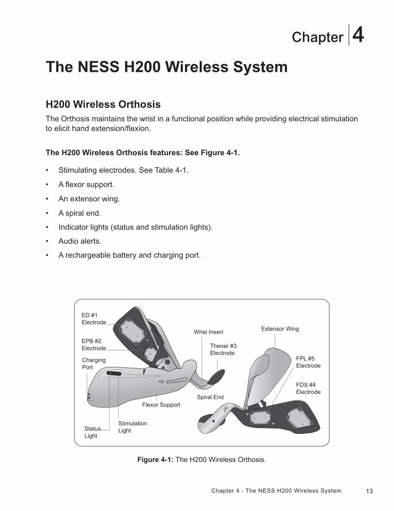
H200 Wireless OrthosisThe Orthosis maintains the wrist in a functional position while providing electrical stimulation to elicit hand extension/flexion.
The H200 Wireless Orthosis features: See Figure 4-1.
• Stimulating electrodes. See Table 4-1.
• A flexor support.
• An extensor wing.
• A spiral end.
• Indicator lights (status and stimulation lights).
• Audio alerts.
• A rechargeable battery and charging port.
Thenar #3 Electrode
Wrist Insert
ED #1 Electrode
Spiral EndFlexor Support
EPB #2 Electrode
Status Light
Stimulation Light
Extensor Wing
FDS #4 Electrode
FPL #5 Electrode
Figure 4-1: The H200 Wireless Orthosis.
Charging Port
14 Clinician's Guide
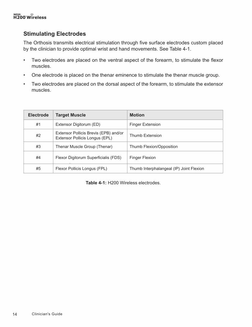
Stimulating Electrodes
The Orthosis transmits electrical stimulation through five surface electrodes custom placed by the clinician to provide optimal wrist and hand movements. See Table 4-1.
• Two electrodes are placed on the ventral aspect of the forearm, to stimulate the flexor muscles.
• One electrode is placed on the thenar eminence to stimulate the thenar muscle group.
• Two electrodes are placed on the dorsal aspect of the forearm, to stimulate the extensor muscles.
Table 4-1: H200 Wireless electrodes.
Electrode Target Muscle Motion
#1 Extensor Digitorum (ED) Finger Extension
#2Extensor Pollicis Brevis (EPB) and/or Extensor Pollicis Longus (EPL)
Thumb Extension
#3 Thenar Muscle Group (Thenar) Thumb Flexion/Opposition
#4 Flexor Digitorum Superficialis (FDS) Finger Flexion
#5 Flexor Pollicis Longus (FPL) Thumb Interphalangeal (IP) Joint Flexion
15Chapter 4 - The NESS H200 Wireless System
Flexor Support
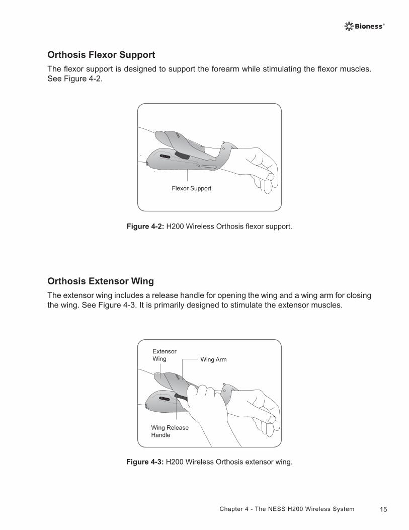
Orthosis Flexor Support
The flexor support is designed to support the forearm while stimulating the flexor muscles. See Figure 4-2.
Figure 4-2: H200 Wireless Orthosis flexor support.
Orthosis Extensor Wing
The extensor wing includes a release handle for opening the wing and a wing arm for closing the wing. See Figure 4-3. It is primarily designed to stimulate the extensor muscles.
Figure 4-3: H200 Wireless Orthosis extensor wing.
Wing Arm
Wing Release Handle
Extensor Wing
16 Clinician's Guide
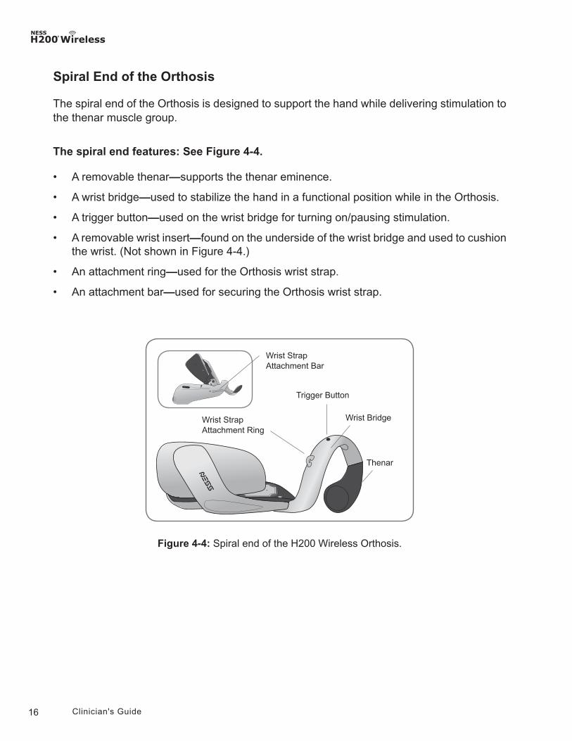
Figure 4-4: Spiral end of the H200 Wireless Orthosis.
Thenar
Wrist Strap Attachment Ring
Wrist Strap Attachment Bar
Wrist Bridge
Trigger Button
Spiral End of the Orthosis
The spiral end of the Orthosis is designed to support the hand while delivering stimulation to the thenar muscle group.
The spiral end features: See Figure 4-4.
• A removable thenar—supports the thenar eminence.
• A wrist bridge—used to stabilize the hand in a functional position while in the Orthosis.
• A trigger button—used on the wrist bridge for turning on/pausing stimulation.
• A removable wrist insert—found on the underside of the wrist bridge and used to cushion the wrist. (Not shown in Figure 4-4.)
• An attachment ring—used for the Orthosis wrist strap.
• An attachment bar—used for securing the Orthosis wrist strap.
17Chapter 4 - The NESS H200 Wireless System
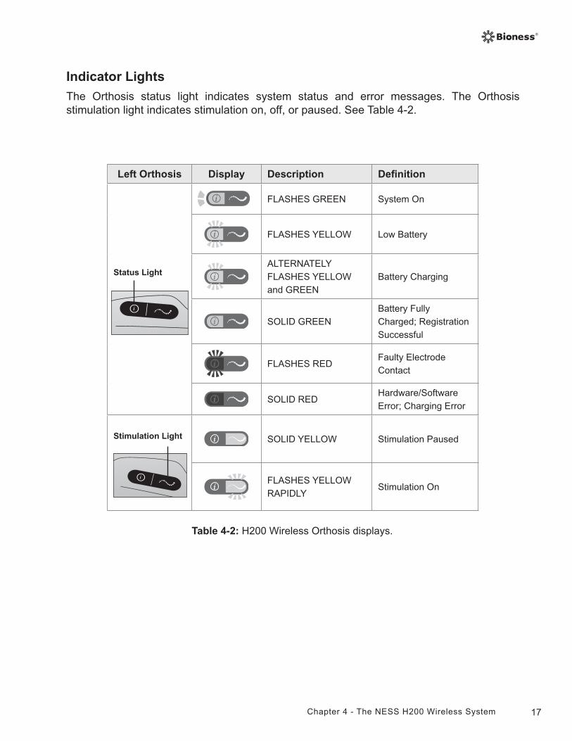
Indicator Lights
The Orthosis status light indicates system status and error messages. The Orthosis stimulation light indicates stimulation on, off, or paused. See Table 4-2.
Table 4-2: H200 Wireless Orthosis displays.
Left Orthosis Display Description Definition
Status Light
FLASHES GREEN System On
FLASHES YELLOW Low Battery
ALTERNATELY FLASHES YELLOW and GREEN
Battery Charging
SOLID GREENBattery Fully Charged; Registration Successful
FLASHES REDFaulty Electrode Contact
SOLID REDHardware/Software Error; Charging Error
Stimulation Light SOLID YELLOW Stimulation Paused
FLASHES YELLOW RAPIDLY
Stimulation On
18 Clinician's Guide
Audio Alerts
The Orthosis beeps when:
• A charger is connected.
• Electrode contact is faulty.
• A charging error has occurred.
• The battery charge level is low.
• Stimulation is turned on/off or paused.
• The NESS H200 Wireless System is turned on/off.
• The H200 Wireless Orthosis stimulation unit malfunctions.
19Chapter 4 - The NESS H200 Wireless System
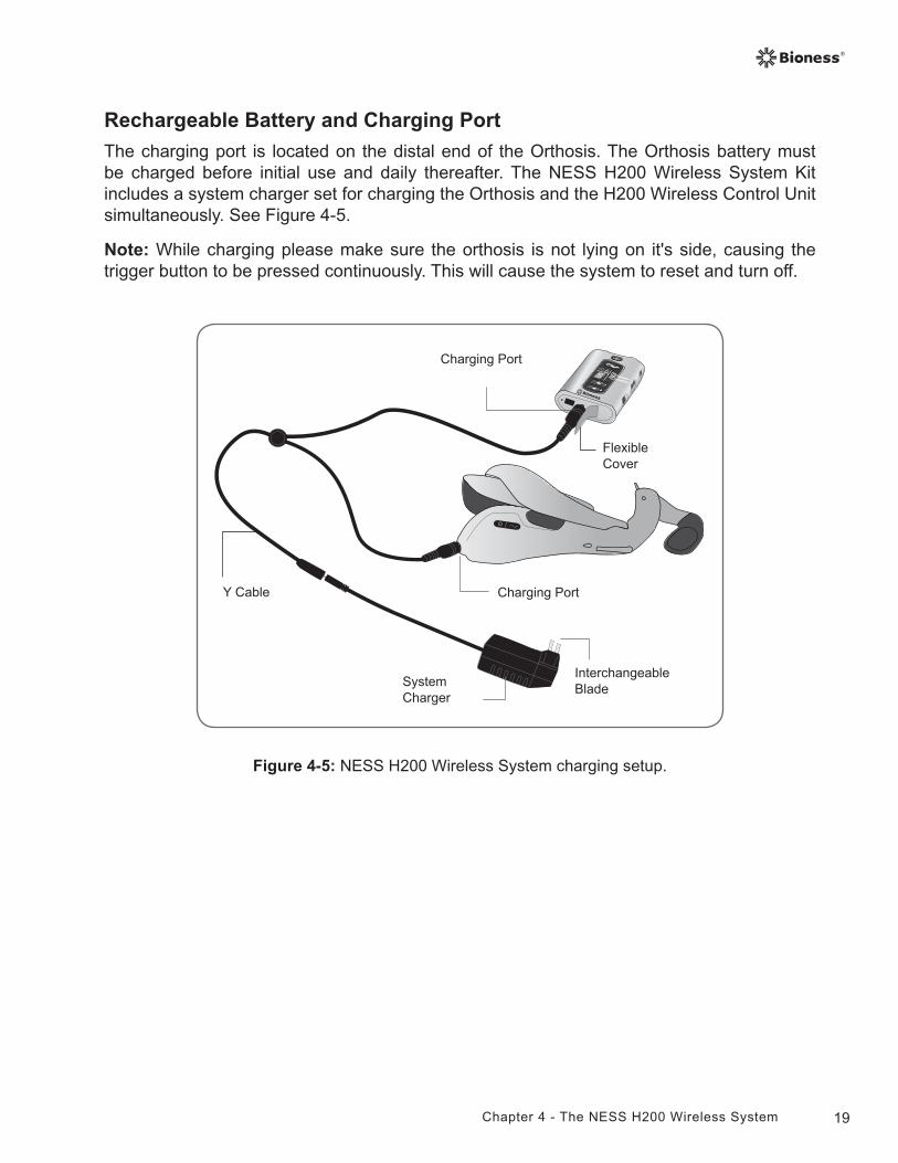
Figure 4-5: NESS H200 Wireless System charging setup.
Flexible Cover
Charging Port
Charging Port
System Charger
Y Cable
Interchangeable Blade
Rechargeable Battery and Charging Port
The charging port is located on the distal end of the Orthosis. The Orthosis battery must be charged before initial use and daily thereafter. The NESS H200 Wireless System Kit includes a system charger set for charging the Orthosis and the H200 Wireless Control Unit simultaneously. See Figure 4-5.
Note: While charging please make sure the orthosis is not lying on it's side, causing the trigger button to be pressed continuously. This will cause the system to reset and turn off.
20 Clinician's Guide
H200 Wireless Control UnitThe Control Unit communicates wirelessly with the Orthosis to turn on/off and pause stimulation, adjust stimulation intensity, and monitor system status.
The H200 Wireless Control Unit features:
• Operating buttons.
• On/off lights.
• Operating modes.
• Indicators and a digital display.
• Audio alerts.
• A rechargeable battery and charging port.
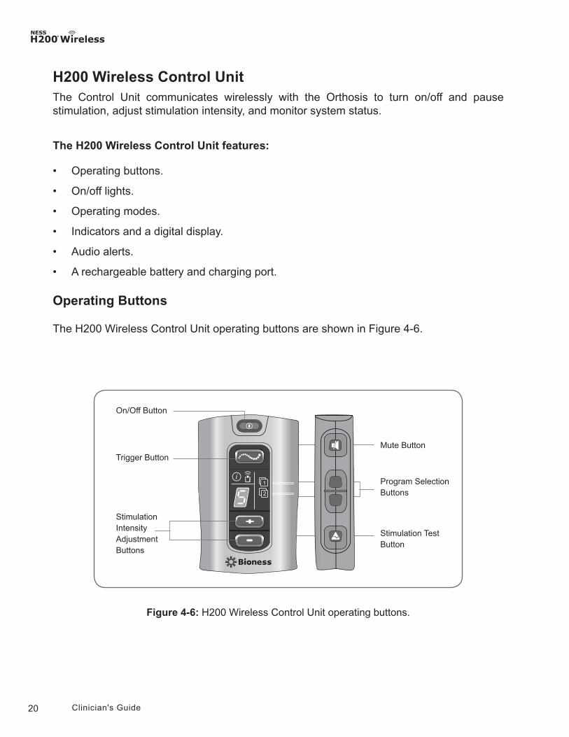
Operating Buttons
The H200 Wireless Control Unit operating buttons are shown in Figure 4-6.
Figure 4-6: H200 Wireless Control Unit operating buttons.
Mute Button
Stimulation Test Button
On/Off Button
Trigger Button
Stimulation Intensity AdjustmentButtons
Program Selection Buttons
21Chapter 4 - The NESS H200 Wireless System
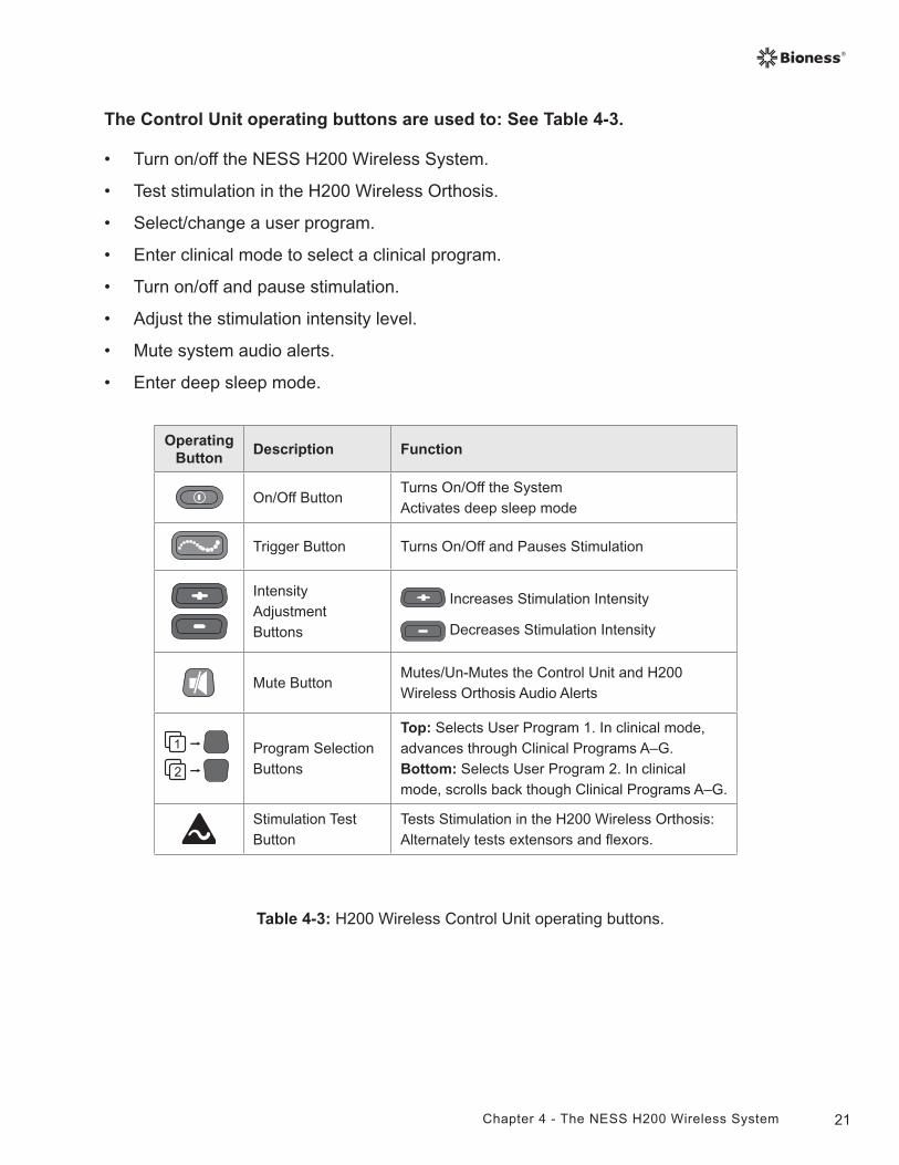
Table 4-3: H200 Wireless Control Unit operating buttons.
Operating Button
Description Function
On/Off ButtonTurns On/Off the SystemActivates deep sleep mode
Trigger Button Turns On/Off and Pauses Stimulation
Intensity AdjustmentButtons
Increases Stimulation Intensity
Decreases Stimulation Intensity
Mute ButtonMutes/Un-Mutes the Control Unit and H200 Wireless Orthosis Audio Alerts
Program Selection Buttons
Top: Selects User Program 1. In clinical mode, advances through Clinical Programs A–G.Bottom: Selects User Program 2. In clinical mode, scrolls back though Clinical Programs A–G.
Stimulation Test Button
Tests Stimulation in the H200 Wireless Orthosis: Alternately tests extensors and flexors.
The Control Unit operating buttons are used to: See Table 4-3.
• Turn on/off the NESS H200 Wireless System.
• Test stimulation in the H200 Wireless Orthosis.
• Select/change a user program.
• Enter clinical mode to select a clinical program.
• Turn on/off and pause stimulation.
• Adjust the stimulation intensity level.
• Mute system audio alerts.
• Enter deep sleep mode.
22 Clinician's Guide
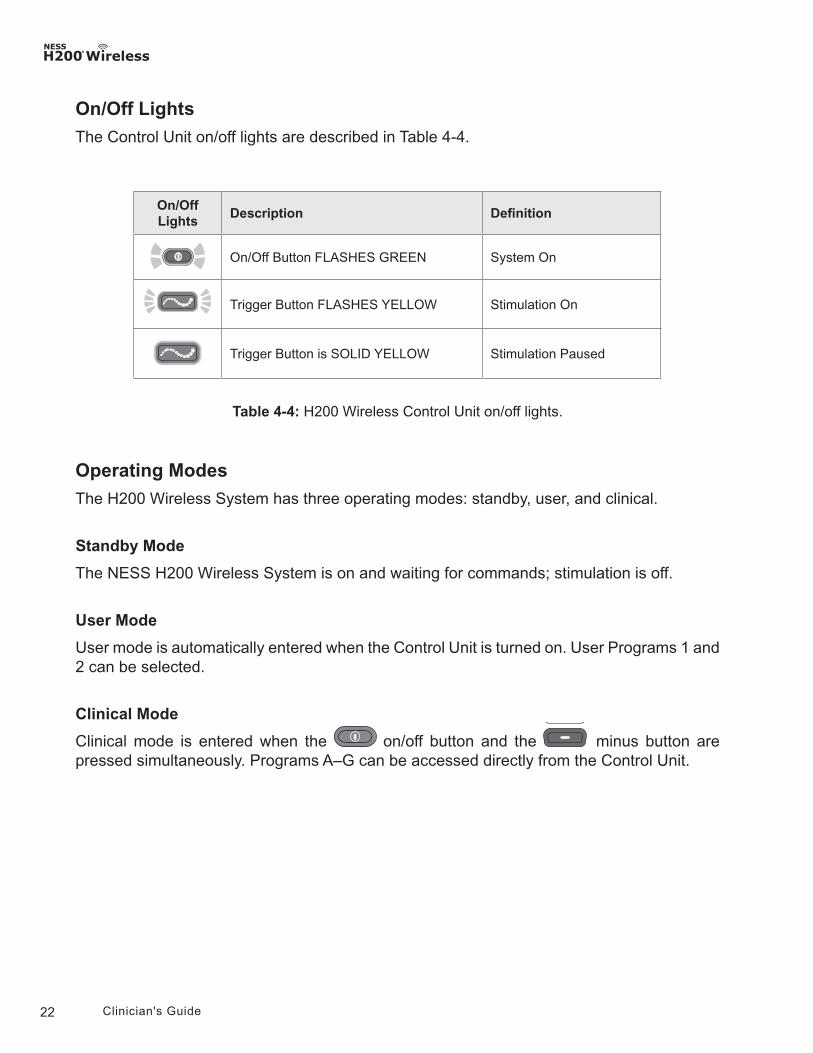
On/Off Lights
The Control Unit on/off lights are described in Table 4-4.
Table 4-4: H200 Wireless Control Unit on/off lights.
On/Off Lights
Description Definition
On/Off Button FLASHES GREEN System On
Trigger Button FLASHES YELLOW Stimulation On
Trigger Button is SOLID YELLOW Stimulation Paused
Operating Modes
The H200 Wireless System has three operating modes: standby, user, and clinical.
Standby Mode
The NESS H200 Wireless System is on and waiting for commands; stimulation is off.
User Mode
User mode is automatically entered when the Control Unit is turned on. User Programs 1 and 2 can be selected.
Clinical Mode
Clinical mode is entered when the on/off button and the minus button are pressed simultaneously. Programs A–G can be accessed directly from the Control Unit.
23Chapter 4 - The NESS H200 Wireless System
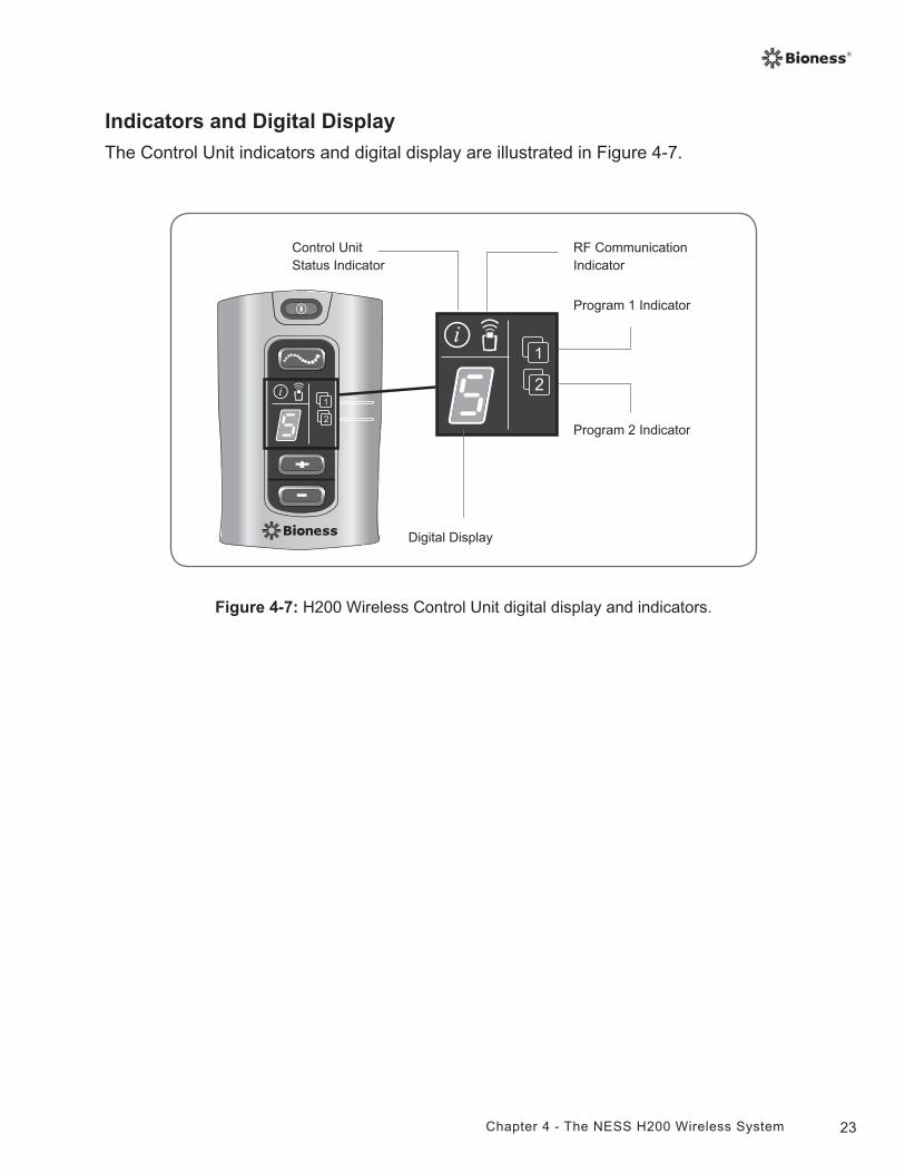
Figure 4-7: H200 Wireless Control Unit digital display and indicators.
Indicators and Digital Display
The Control Unit indicators and digital display are illustrated in Figure 4-7.
Digital Display
Program 2 Indicator
Control Unit Status Indicator
Program 1 Indicator
RF Communication Indicator
24 Clinician's Guide
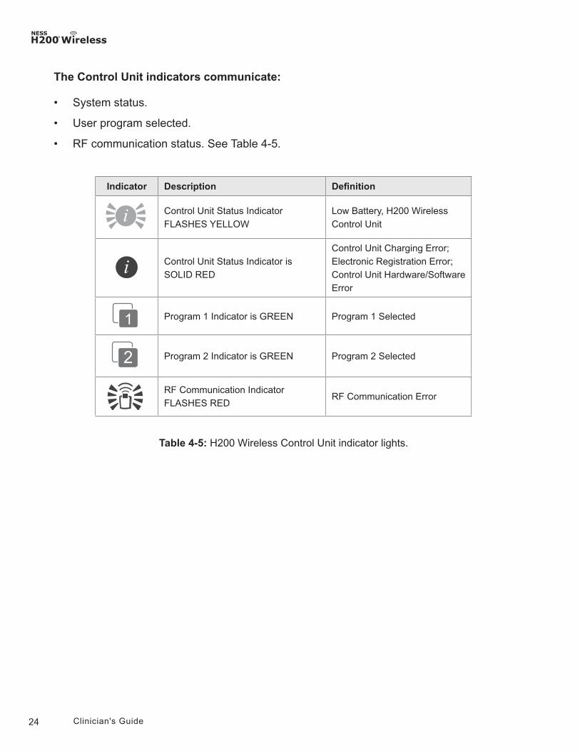
Table 4-5: H200 Wireless Control Unit indicator lights.
The Control Unit indicators communicate:
• System status.
• User program selected.
• RF communication status. See Table 4-5.
Indicator Description Definition
Control Unit Status Indicator FLASHES YELLOW
Low Battery, H200 Wireless Control Unit
Control Unit Status Indicator is SOLID RED
Control Unit Charging Error; Electronic Registration Error; Control Unit Hardware/Software Error
Program 1 Indicator is GREEN Program 1 Selected
Program 2 Indicator is GREEN Program 2 Selected
RF Communication Indicator FLASHES RED
RF Communication Error
25Chapter 4 - The NESS H200 Wireless System
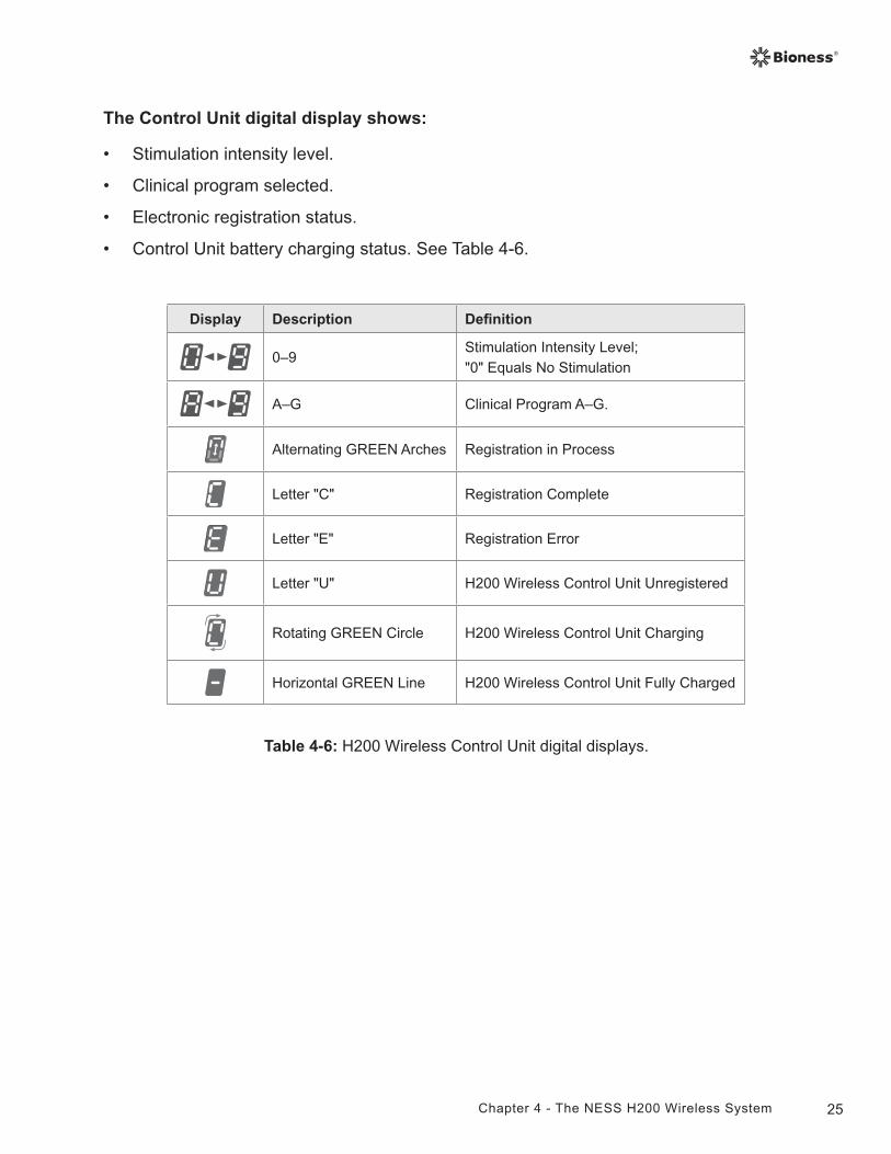
Table 4-6: H200 Wireless Control Unit digital displays.
The Control Unit digital display shows:
• Stimulation intensity level.
• Clinical program selected.
• Electronic registration status.
• Control Unit battery charging status. See Table 4-6.
Display Description Definition
0–9Stimulation Intensity Level;"0" Equals No Stimulation
A–G Clinical Program A–G.
Alternating GREEN Arches Registration in Process
Letter "C" Registration Complete
Letter "E" Registration Error
Letter "U" H200 Wireless Control Unit Unregistered
Rotating GREEN Circle H200 Wireless Control Unit Charging
Horizontal GREEN Line H200 Wireless Control Unit Fully Charged
26 Clinician's Guide
Audio Alerts
The H200 Wireless Control Unit beeps to indicate:
• A button was pressed.
• RF communication failed.
• A charging error occurred.
• The audio alerts were muted/un-muted.
• A charger was connected or disconnected.
• The NESS H200 Wireless System was turned on/off.
• The H200 Wireless Control Unit battery charge level is low.
• An H200 Wireless Control Unit hardware/software error occurred.
• The electronic registration process was initiated, successful, or unsuccessful.
27Chapter 4 - The NESS H200 Wireless System
Rechargeable Battery and Charging Port
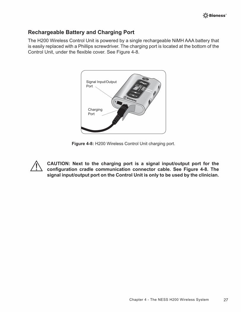
The H200 Wireless Control Unit is powered by a single rechargeable NiMH AAA battery that is easily replaced with a Phillips screwdriver. The charging port is located at the bottom of the Control Unit, under the flexible cover. See Figure 4-8.
Figure 4-8: H200 Wireless Control Unit charging port.
Signal Input/Output Port
Charging Port
CAUTION: Next to the charging port is a signal input/output port for the configuration cradle communication connector cable. See Figure 4-8. The signal input/output port on the Control Unit is only to be used by the clinician.
28 Clinician's Guide
H200 Wireless Clinical Programs
The H200 Wireless System supports:
• Functional Training Programs.
• Neuroprosthesis Programs.
• Motor Neuromodulation Program.
• Personal Preset Programs.
• Custom Personal Programming
Functional Training Programs
There are three functional Training Programs A, B, and C that are designed to exercise the hand. They consist of repetitive motions with a relaxation pause between each motion. They begin when the trigger button on the Control Unit or Orthosis is pressed. They end when the programmed training time finishes. Training time can range from 5 to 120 minutes.
Program A—Grasp and Release
Activates sequential opening and closing of the hand. Pressing the trigger button starts the stimulation to open the hand. The hand then closes and opens, with a pause between each phase. Stimulation intensity and the duration of the extension and flexion phases can be adjusted, as can total program time.
Program B—Open Hand
Activates the extensor muscles only. When the trigger button is pressed, hand extension is followed by a period of relaxation, and then hand extension repeats. Stimulation intensity and the duration of the extension and relaxation phases can be adjusted, as can total program time.
Program C—Grasp
Activates sequential closing of the hand. When the trigger button is pressed, hand flexion is followed by a period of relaxation, and then hand flexion repeats. Stimulation intensity and the duration of the flexion and relaxation phases can be adjusted, as can the total program time.
29Chapter 4 - The NESS H200 Wireless System
Neuroprosthesis Programs
There are three Neuroprosthesis Programs D, E, and F that are designed to help perform a specific task, such as opening a door or grasping an object. They start when the trigger button on the Control Unit or Orthosis is pressed. They continue until the trigger button is pressed again. Neuroprosthesis programs have no set program time. The duration is determined by task/user.
Program D—Open Hand
Activates the hand to open and remain open until the trigger button is pressed again.
Program E—Grasp and Release
Activates the hand to grasp and hold objects using a palmar grasp. When the trigger button is pressed, a half-second pause is followed by a pre-defined duration of hand opening. The hand then closes and remains closed until the trigger button is pressed again to release the grasp. Once the trigger button is pressed the second time, a half second of continued flexor stimulation is followed by an adjustable duration of extensor stimulation to open the hand. The stimulation then shuts off, and the hand relaxes.
Program F—Key Grip
Program F is used to grasp and hold small items in a lateral grasp (or key grip) between the thumb and the lateral side of the index finger. Program F holds the fingers in flexion throughout the operating phases.
When the trigger button is pressed, the thumb opens. The thumb then closes and remains closed until the trigger button is pressed again to release the grip. Once the trigger button is pressed the second time, extensor stimulation opens the thumb. The stimulation then shuts off, and the hand relaxes.
Motor Neuromodulation Program
Program G—Extensors and Flexors, Extensors Only, Flexors Only
There is one Motor Neuromodulation Program G that delivers rapid bursts of stimulation to the flexors and extensors, the flexors only, or the extensors only. The program is started and paused by pressing the trigger button on the Control Unit or Orthosis. Program time can range from 5 to 30 minutes.
30 Clinician's Guide
Personal Preset Programs
The Personal Preset Programs address patient variances in:
• Voluntary movement of the wrist and fingers.
• Finger response to motor neuromodulation.
• Tone.
The three Personal Preset Program consists of a series of Functional Training and Motor Neuromodulation Program segments that cycle for a total programmed time. Each program may have up to eight exercises with intermittent rest periods. Personal programs begin when the trigger button on the Control Unit or Orthosis is pressed. They end when the program time elapses. Program time can range from 30 to 240 minutes.
• Personal Preset 1—For all patients during initial use. Thereafter, for patients with a high level of flexor tone.
• Personal Preset 2—For patients with moderate flexor tone.
• Personal Preset 3—For patients with mild flexor tone.
Personal Custom Programming
A Personal Custom Program is a clinician-configured program that may include up to eight program segments and 7 rest periods. The clinician customizes the program by adding, deleting, and reordering program segments and adjusting segment duration. Program time can range from 30 to 240 minutes.
31Chapter 4 - The NESS H200 Wireless System
Operating the NESS H200 Wireless System
Turning the System On/Off
Press the on/off button on the Control Unit once.
When the system is on:
• The on/off button on the Control Unit will FLASH GREEN.
• The status light on the Orthosis will FLASH GREEN.
Testing Stimulation in the H200 Wireless Orthosis
1. Verify that the system is on. The trigger button should not be lit.
2. Press and hold the stimulation test button to test stimulation of the extensor muscles. Stimulation will turn on and stay on until the button is released. When stimulation is on, the trigger button will FLASH YELLOW RAPIDLY.
3. Release the stimulation test button to turn off stimulation.
4. Repeat to test stimulation of the flexor muscles.
Selecting a User Program
During the clinical/therapy session, the clinician will select the clinical programs that best fit the patient's therapeutic needs, customize the programs, and then, for home users, assign two of the clinical programs to Program Buttons 1 and 2 on the H200 Wireless Control Unit.
To select a User Program turn on the system. User Program 1 is selected automatically. The Program 1 indicator will be GREEN. To select User Program 2, press the Program 2
selection button.
Entering Clinical Mode
With the system off, press and hold the minus button and the on/off button until the H200 Wireless Control Unit beeps and program letter "A" and the stimulation intensity level alternate in the digital display. To exit clinical mode, press the on/off button.
Selecting a Clinical Program
While in clinical mode, press the top or bottom program selection button on the H200 Wireless Control Unit until the desired program letter appears in the digital display.
32 Clinician's Guide
Turning On Stimulation
Press the trigger button on the H200 Wireless Control Unit or the trigger button on the Orthosis.
Pausing Stimulation
Press the trigger button on the H200 Wireless Control Unit or the trigger button on the Orthosis.
Note: Neuroprosthesis Programs cannot be paused. Pressing the trigger button when stimulation is on starts the second phase of a Neuroprosthesis Program.
Turning Off Stimulation
Press the on/off button or the trigger button on the Control Unit, or press the trigger button on the Orthosis.
Note: To stop stimulation immediately press the on/off button in a Neuroprosthesis Program.
Adjusting Stimulation Intensity
Press the plus or minus button on the Control Unit once to increase/decrease stimulation intensity one level. The Control Unit will beep with each change in level and it will show in the digital display.
Note: An intensity level of “0” equals no stimulation.
Muting/Un-Muting the System Audio Alerts
Press the mute button briefly. The mute button is located on the side of the Control Unit.
Entering and Exiting Deep Sleep Mode
With the system off, press and hold the on/off button for ten seconds. The Control Unit and Orthosis will beep and the Orthosis lights will flash when entering deep sleep mode. To exit deep sleep mode, press the Orthosis trigger button.
Note: Deep sleep mode is a power saving feature that shuts down the system and displays no indications. The use of deep sleep mode is recommended for extended periods of non-use.
33Chapter 5 - NESS H200 Wireless Clinician's Kit
5Chapter
NESS H200 Wireless Clinician’s Kit
The NESS H200 Wireless Clinician’s Kit is used to fit and program the NESS H200 Wireless System. The small/medium Clinician’s Kit is for fitting small/medium Orthoses. The large Clinician’s Kit is for fitting the large Orthosis.
H200 Wireless Clinician’s Kit (small/medium)
PDA Components
• HP iPAQ Clinician’s Programmer with H200 Wireless® Software
• HP iPAQ Configuration Cradle with Stylus
• HP iPAQ Clinician’s Programmer Charger
Accessories
• Thenars: Left/Right, Regular/Large (small/medium)
• Thenar Screws
• Wrist Inserts: Left/Right, Thick/Medium/Thin (small/medium)
• Wrist Insert Screws (small/medium)
• Wrist Insert Covers (small/medium)
• H200 Wireless FPL Panels: Left/Right (small/medium)
• FPL Panel Screws (small/medium)
• Fitting Panel Sets: Left/Right (small/medium)
• H200 Wireless Cloth Electrodes
• Phillips Screwdriver
• H200 Wireless Clinician’s Reference Card
• HP iPAQ Manufacturer’s Instructions
34 Clinician's Guide
H200 Wireless Clinician’s Kit (large)
PDA Components
• HP iPAQ Clinician’s Programmer with H200 Wireless® Software
• HP iPAQ Configuration Cradle with Stylus
• HP iPAQ Clinician’s Programmer Charger
Accessories
• Thenars: Left/Right, Large (large)
• Thenar Screws
• Wrist Inserts: Left/Right, Thick/Medium/Thin (large)
• Wrist Insert Screws (large)
• Wrist Insert Covers (large)
• H200 Wireless FPL Panels: Left/Right (large)
• FPL Panel Screws (large)
• Fitting Panel Sets: Left/Right (large)
• H200 Wireless Cloth Electrodes
• Phillips Screwdriver
• H200 Wireless Clinician’s Reference Card
• HP iPAQ Manufacturer’s Instructions
The NESS H200 Wireless Clinician’s Upgrade Kit is to be used with the NESS H200 Clinician's Kit to fit and program the NESS H200 Wireless System.
H200 Wireless Clinician’s Upgrade Kit
PDA Components
• HP iPAQ Clinician’s Programmer with H200 Wireless® Software
• HP iPAQ Configuration Cradle with Stylus
• HP iPAQ Clinician’s Programmer Charger
Accessories
• H200 Wireless FPL Panels: Left/Right (small/medium)
• H200 Wireless FPL Panels: Left/Right (large)
35Chapter 5 - NESS H200 Wireless Clinician's Kit
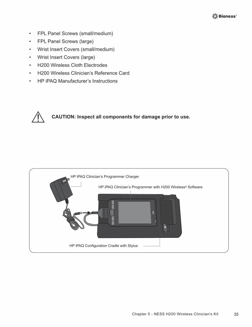
CAUTION: Inspect all components for damage prior to use.
• FPL Panel Screws (small/medium)
• FPL Panel Screws (large)
• Wrist Insert Covers (small/medium)
• Wrist Insert Covers (large)
• H200 Wireless Cloth Electrodes
• H200 Wireless Clinician’s Reference Card
• HP iPAQ Manufacturer’s Instructions
HP iPAQ Clinician’s Programmer with H200 Wireless® Software
HP iPAQ Clinician’s Programmer Charger
HP iPAQ Configuration Cradle with Stylus
36 Clinician's Guide
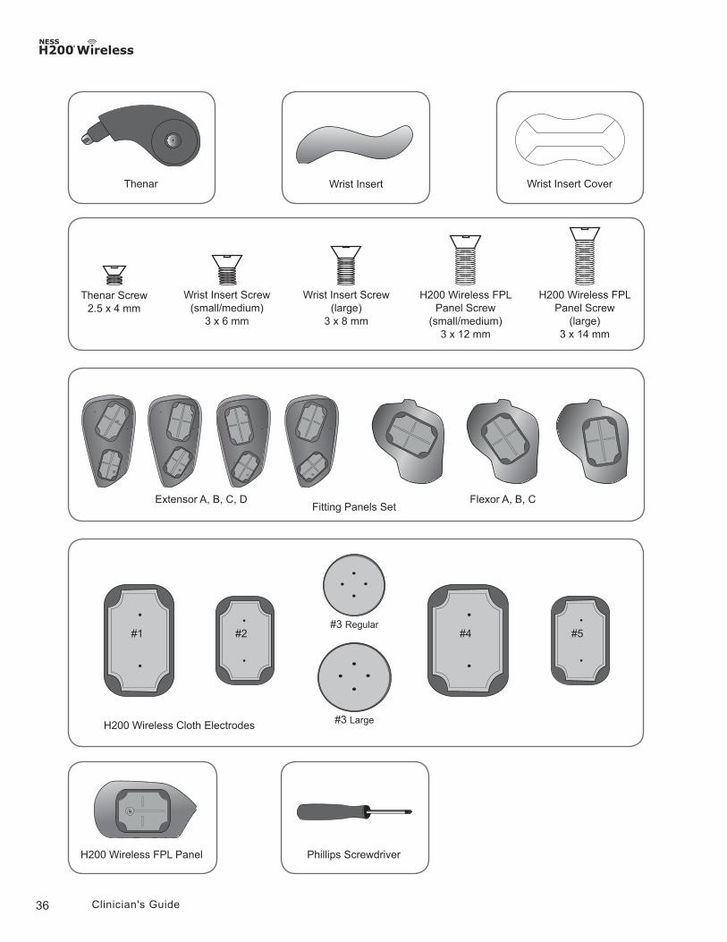
H200 Wireless Cloth Electrodes
#1 #2 #4 #5#3 Regular
#3 Large
Wrist InsertThenar
H200 Wireless FPL Panel
Flexor A, B, CExtensor A, B, C, DFitting Panels Set
Thenar Screw2.5 x 4 mm
Wrist Insert Screw(small/medium)
3 x 6 mm
Wrist Insert Screw(large)
3 x 8 mm
H200 Wireless FPL Panel Screw
(small/medium)3 x 12 mm
H200 Wireless FPL Panel Screw
(large)3 x 14 mm
Wrist Insert Cover
Phillips Screwdriver
37Chapter 5 - NESS H200 Wireless Clinician's Kit
WARNING: The Clinician’s Programmer should only contain the Windows Mobile® operating system and Bioness Inc proprietary software. Third-party software packages are not supported and may interfere with proper operation of the NESS H200 Wireless System, thus voiding the warranty.
PDA Components
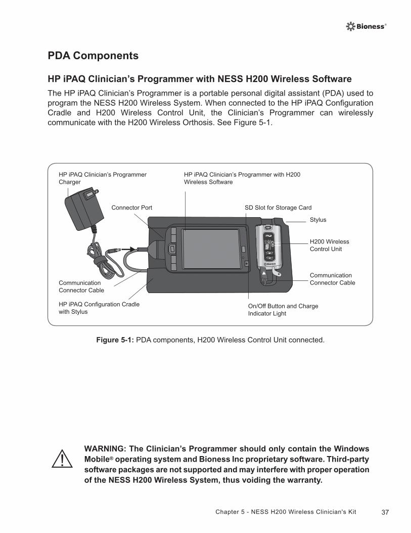
HP iPAQ Clinician’s Programmer with NESS H200 Wireless Software
The HP iPAQ Clinician’s Programmer is a portable personal digital assistant (PDA) used to program the NESS H200 Wireless System. When connected to the HP iPAQ Configuration Cradle and H200 Wireless Control Unit, the Clinician’s Programmer can wirelessly communicate with the H200 Wireless Orthosis. See Figure 5-1.
Figure 5-1: PDA components, H200 Wireless Control Unit connected.
On/Off Button and Charge Indicator Light
HP iPAQ Clinician’s Programmer with H200 Wireless Software
HP iPAQ Clinician’s Programmer Charger
Connector Port SD Slot for Storage Card
H200 Wireless Control Unit
Stylus
Communication Connector Cable
HP iPAQ Configuration Cradle with Stylus
Communication Connector Cable
38 Clinician's Guide
On/Off Button
Used to turn on/off the Clinician’s Programmer.
Charge Indicator Light
The charge indicator light is YELLOW when the Clinician’s Programmer is charging and GREEN when the Clinician’s Programmer battery charge is complete.
SD (Secure Digital) Slot
The SD slot is for the SD card, used to back up and restore the Clinician's Programmer database.
Connector Port
Used to connect the Clinician’s Programmer to the communication connector cable on the HP iPAQ Configuration Cradle.
HP iPAQ Configuration Cradle with Stylus
The HP iPAQ Configuration Cradle connects the Clinician’s Programmer to the H200 Wireless Control Unit and to the Clinician’s Programmer Charger. The stylus is for software navigation.
HP iPAQ Clinician’s Programmer Charger
Used to charge the Clinician’s Programmer battery. Use only the Clinician’s Programmer Charger included in the H200 Wireless Clinician’s Kit.
39Chapter 5 - NESS H200 Wireless Clinician's Kit
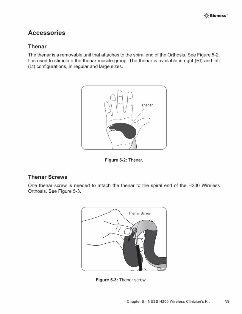
Figure 5-2: Thenar.
Thenar
Accessories
Thenar
The thenar is a removable unit that attaches to the spiral end of the Orthosis. See Figure 5-2. It is used to stimulate the thenar muscle group. The thenar is available in right (Rt) and left (Lt) configurations, in regular and large sizes.
Figure 5-3: Thenar screw.
Thenar Screws
One thenar screw is needed to attach the thenar to the spiral end of the H200 Wireless Orthosis. See Figure 5-3.
Thenar Screw
40 Clinician's Guide
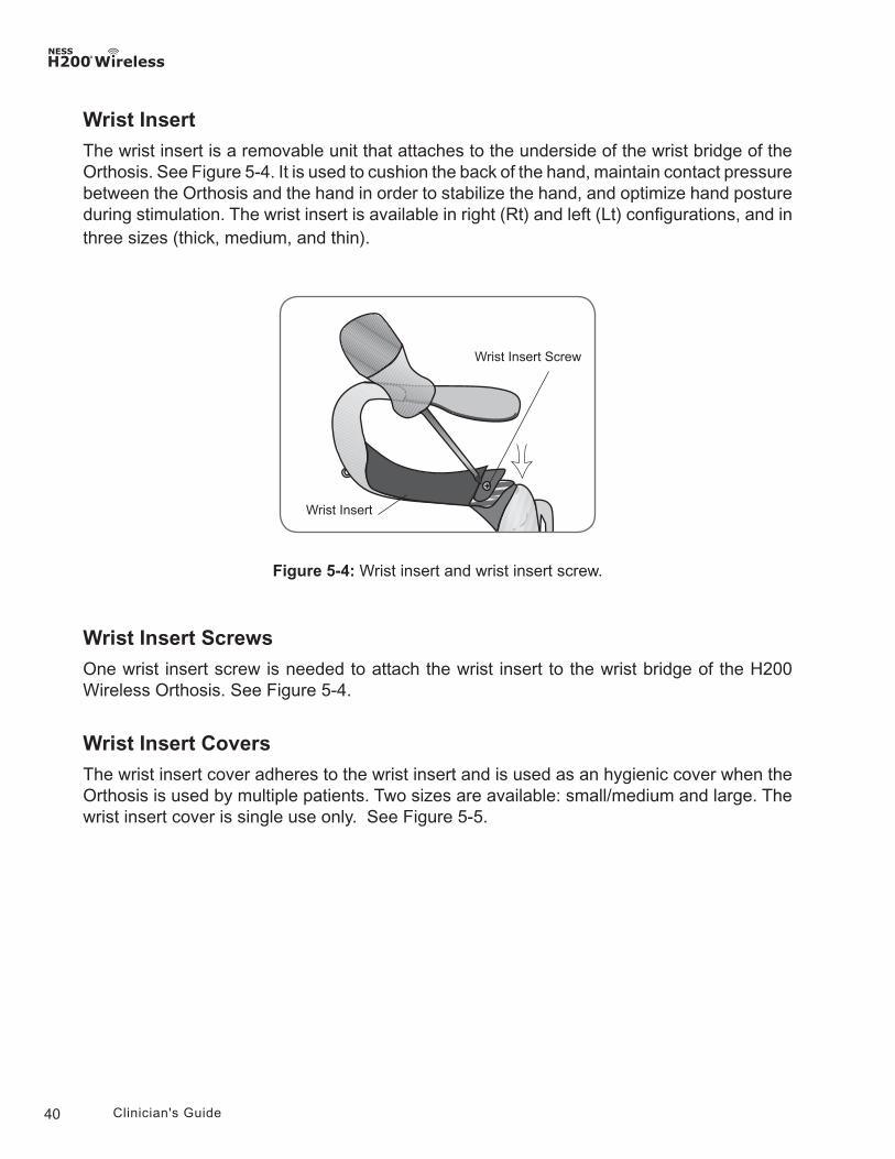
Wrist Insert Screws
One wrist insert screw is needed to attach the wrist insert to the wrist bridge of the H200 Wireless Orthosis. See Figure 5-4.
Wrist Insert Covers
The wrist insert cover adheres to the wrist insert and is used as an hygienic cover when the Orthosis is used by multiple patients. Two sizes are available: small/medium and large. The wrist insert cover is single use only. See Figure 5-5.
Wrist Insert
The wrist insert is a removable unit that attaches to the underside of the wrist bridge of the Orthosis. See Figure 5-4. It is used to cushion the back of the hand, maintain contact pressure between the Orthosis and the hand in order to stabilize the hand, and optimize hand posture during stimulation. The wrist insert is available in right (Rt) and left (Lt) configurations, and in three sizes (thick, medium, and thin).
Figure 5-4: Wrist insert and wrist insert screw.
Wrist Insert Screw
Wrist Insert
41Chapter 5 - NESS H200 Wireless Clinician's Kit
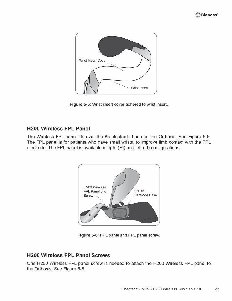
Figure 5-5: Wrist insert cover adhered to wrist insert.
Wrist Insert Cover
Wrist Insert
Figure 5-6: FPL panel and FPL panel screw.
FPL #5Electrode Base
H200 Wireless FPL Panel and Screw
H200 Wireless FPL Panel
The Wireless FPL panel fits over the #5 electrode base on the Orthosis. See Figure 5-6. The FPL panel is for patients who have small wrists, to improve limb contact with the FPL electrode. The FPL panel is available in right (Rt) and left (Lt) configurations.
H200 Wireless FPL Panel Screws
One H200 Wireless FPL panel screw is needed to attach the H200 Wireless FPL panel to the Orthosis. See Figure 5-6.
42 Clinician's Guide
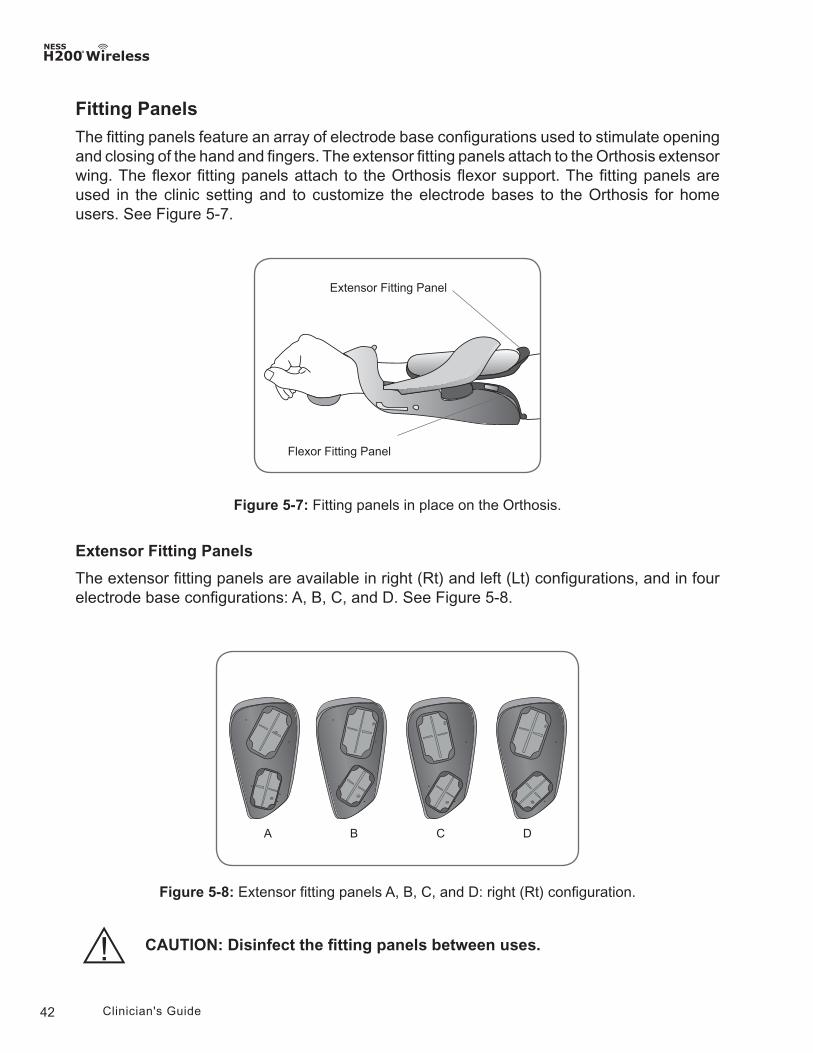
Figure 5-7: Fitting panels in place on the Orthosis.
Fitting Panels
The fitting panels feature an array of electrode base configurations used to stimulate opening and closing of the hand and fingers. The extensor fitting panels attach to the Orthosis extensor wing. The flexor fitting panels attach to the Orthosis flexor support. The fitting panels are used in the clinic setting and to customize the electrode bases to the Orthosis for home users. See Figure 5-7.
Extensor Fitting Panel
Flexor Fitting Panel
Extensor Fitting Panels
The extensor fitting panels are available in right (Rt) and left (Lt) configurations, and in four electrode base configurations: A, B, C, and D. See Figure 5-8.
Figure 5-8: Extensor fitting panels A, B, C, and D: right (Rt) configuration.
BA C D
CAUTION: Disinfect the fitting panels between uses.
43Chapter 5 - NESS H200 Wireless Clinician's Kit
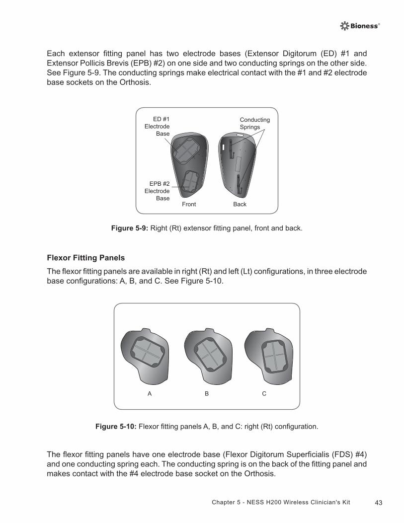
Front Back
ED #1Electrode
Base
EPB #2Electrode
Base
Conducting Springs
Figure 5-9: Right (Rt) extensor fitting panel, front and back.
Each extensor fitting panel has two electrode bases (Extensor Digitorum (ED) #1 and Extensor Pollicis Brevis (EPB) #2) on one side and two conducting springs on the other side. See Figure 5-9. The conducting springs make electrical contact with the #1 and #2 electrode base sockets on the Orthosis.
BA C
Flexor Fitting Panels
The flexor fitting panels are available in right (Rt) and left (Lt) configurations, in three electrode base configurations: A, B, and C. See Figure 5-10.
Figure 5-10: Flexor fitting panels A, B, and C: right (Rt) configuration.
The flexor fitting panels have one electrode base (Flexor Digitorum Superficialis (FDS) #4) and one conducting spring each. The conducting spring is on the back of the fitting panel and makes contact with the #4 electrode base socket on the Orthosis.
44 Clinician's Guide
Electrode Base Set
The electrode base set is used to customize the electrode positions for home-use Orthoses.
Electrode Base Screw and Washer Set
The electrode base screw and washer set is used to attach electrode bases #1, #2, and #4 to home-use H200 Wireless Orthoses. Use one screw and one washer for each electrode base.
H200 Wireless Cloth Electrodes
The H200 Wireless Orthosis uses five cloth electrodes. The electrodes insert to the electrode bases. The cloth electrodes are made from a non-woven cotton/polymer fabric designed to retain moisture while the H200 Wireless Orthosis is on the arm. The cloth electrodes must be wet before use and after every three to four hours of use.
The thenar cloth electrode is available in regular and large sizes.
CAUTION: Do not use the NESS H200 Wireless System without the cloth electrodes.
CAUTION: The H200 Wireless cloth electrodes must be wet before use and wet again after every four hours of use.
CAUTION: The H200 Wireless cloth electrodes are for single patient use.
CAUTION: The H200 Wireless cloth electrodes must be replaced every two weeks, or sooner if they become damaged.
45Chapter 6 - Fitting the H200 Wireless Orthosis
6Chapter
Fitting the H200 Wireless Orthosis
Before fitting the H200 Wireless Orthosis:
• Wash the patient's hand and forearm with soap and water and remove any lotions or oils.
• Have the patient remove any jewelry from the hand, wrist, and forearm.
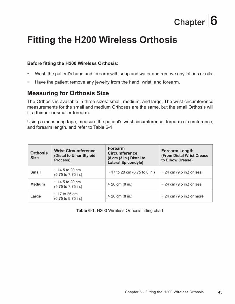
Measuring for Orthosis SizeThe Orthosis is available in three sizes: small, medium, and large. The wrist circumference measurements for the small and medium Orthoses are the same, but the small Orthosis will fit a thinner or smaller forearm.
Using a measuring tape, measure the patient's wrist circumference, forearm circumference, and forearm length, and refer to Table 6-1.
Orthosis Size
Wrist Circumference(Distal to Ulnar Styloid Process)
ForearmCircumference(8 cm (3 in.) Distal to Lateral Epicondyle)
Forearm Length(From Distal Wrist Crease to Elbow Crease)
Small~ 14.5 to 20 cm(5.75 to 7.75 in.)
~ 17 to 20 cm (6.75 to 8 in.) ~ 24 cm (9.5 in.) or less
Medium~ 14.5 to 20 cm(5.75 to 7.75 in.)
> 20 cm (8 in.) ~ 24 cm (9.5 in.) or less
Large~ 17 to 25 cm(6.75 to 9.75 in.)
> 20 cm (8 in.) ~ 24 cm (9.5 in.) or more
Table 6-1: H200 Wireless Orthosis fitting chart.
46 Clinician's Guide
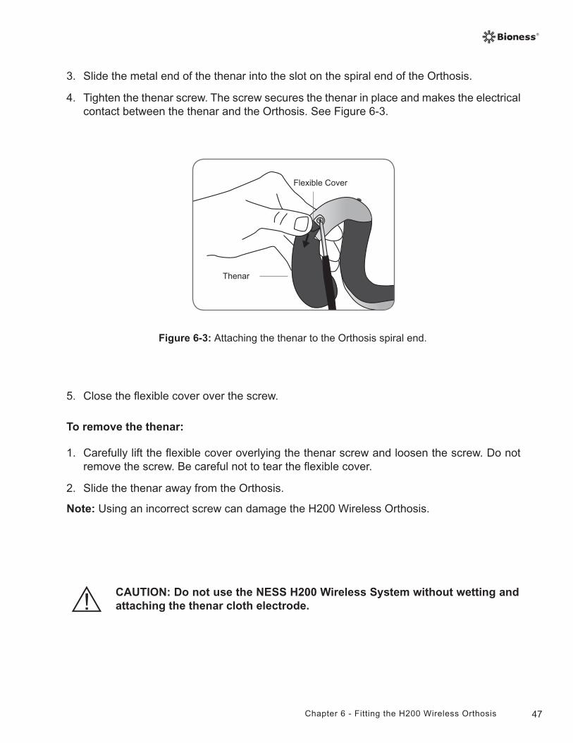
To fit the thenar:
1. Choose a thenar of appropriate size and configuration.
2. Pull back the flexible cover on the thenar to expose the metal. See Figure 6-2.
Figure 6-2: Thenar.
Metal
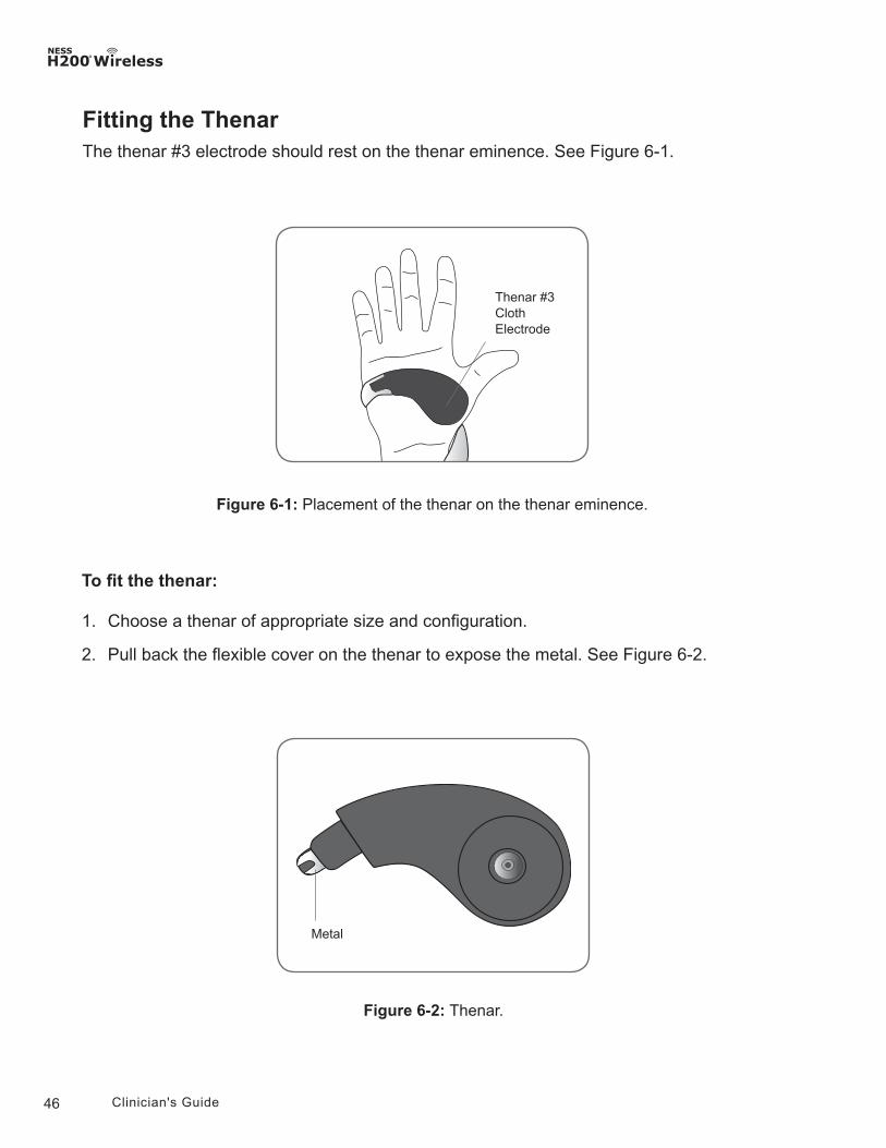
Fitting the ThenarThe thenar #3 electrode should rest on the thenar eminence. See Figure 6-1.
Figure 6-1: Placement of the thenar on the thenar eminence.
Thenar #3 Cloth Electrode
47Chapter 6 - Fitting the H200 Wireless Orthosis
Figure 6-3: Attaching the thenar to the Orthosis spiral end.
Thenar
Flexible Cover
3. Slide the metal end of the thenar into the slot on the spiral end of the Orthosis.
4. Tighten the thenar screw. The screw secures the thenar in place and makes the electrical contact between the thenar and the Orthosis. See Figure 6-3.
5. Close the flexible cover over the screw.
To remove the thenar:
1. Carefully lift the flexible cover overlying the thenar screw and loosen the screw. Do not remove the screw. Be careful not to tear the flexible cover.
2. Slide the thenar away from the Orthosis.
Note: Using an incorrect screw can damage the H200 Wireless Orthosis.
CAUTION: Do not use the NESS H200 Wireless System without wetting and attaching the thenar cloth electrode.
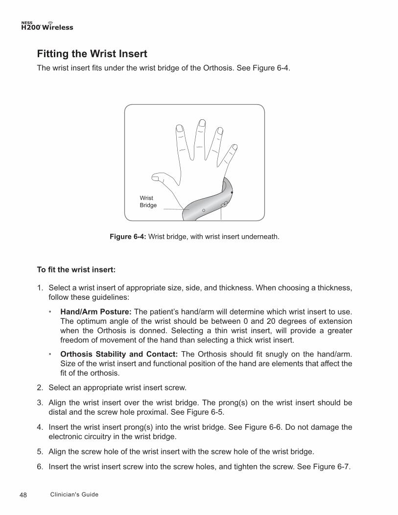
48 Clinician's Guide
Fitting the Wrist InsertThe wrist insert fits under the wrist bridge of the Orthosis. See Figure 6-4.
Figure 6-4: Wrist bridge, with wrist insert underneath.
Wrist Bridge
To fit the wrist insert:
1. Select a wrist insert of appropriate size, side, and thickness. When choosing a thickness, follow these guidelines:
• Hand/Arm Posture: The patient’s hand/arm will determine which wrist insert to use. The optimum angle of the wrist should be between 0 and 20 degrees of extension when the Orthosis is donned. Selecting a thin wrist insert, will provide a greater freedom of movement of the hand than selecting a thick wrist insert.
• Orthosis Stability and Contact: The Orthosis should fit snugly on the hand/arm. Size of the wrist insert and functional position of the hand are elements that affect the fit of the orthosis.
2. Select an appropriate wrist insert screw.
3. Align the wrist insert over the wrist bridge. The prong(s) on the wrist insert should be distal and the screw hole proximal. See Figure 6-5.
4. Insert the wrist insert prong(s) into the wrist bridge. See Figure 6-6. Do not damage the electronic circuitry in the wrist bridge.
5. Align the screw hole of the wrist insert with the screw hole of the wrist bridge.
6. Insert the wrist insert screw into the screw holes, and tighten the screw. See Figure 6-7.
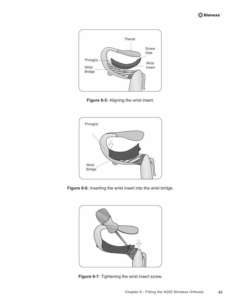
49Chapter 6 - Fitting the H200 Wireless Orthosis
Figure 6-5: Aligning the wrist insert.
Wrist Bridge
Wrist Insert
Prong(s)
Screw Hole
Thenar
Wrist Bridge
Prong(s)
Figure 6-6: Inserting the wrist insert into the wrist bridge.
Figure 6-7: Tightening the wrist insert screw.
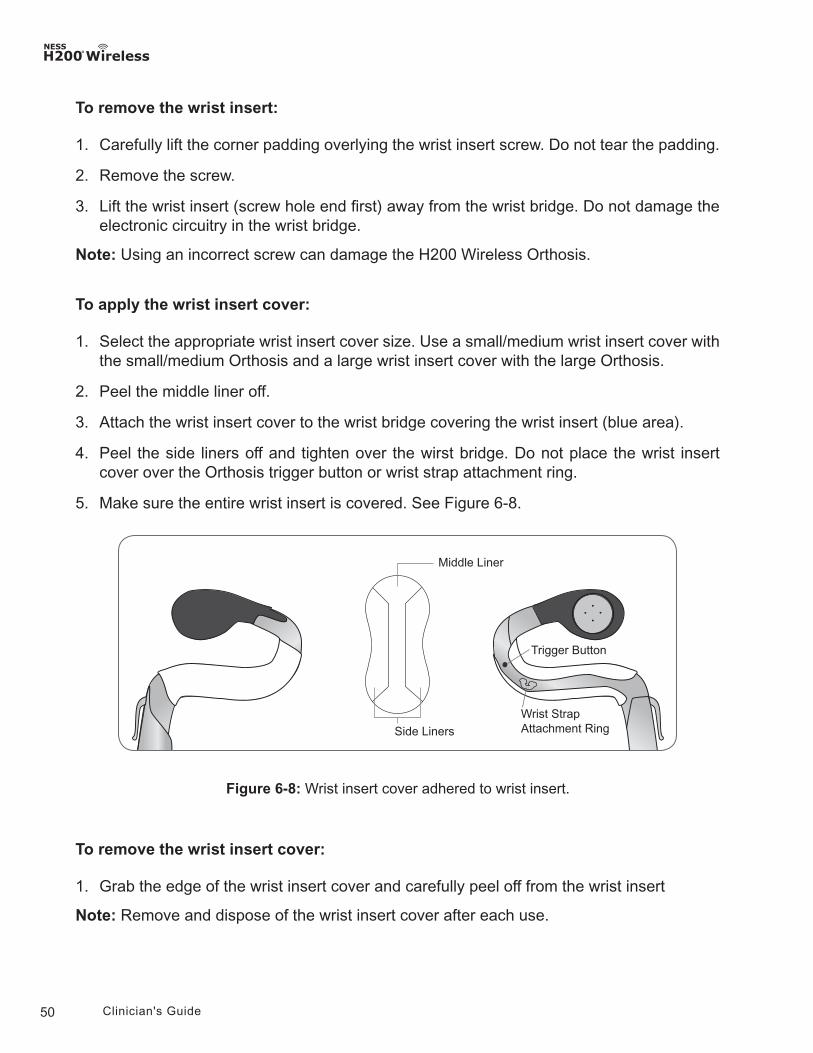
50 Clinician's Guide
To remove the wrist insert:
1. Carefully lift the corner padding overlying the wrist insert screw. Do not tear the padding.
2. Remove the screw.
3. Lift the wrist insert (screw hole end first) away from the wrist bridge. Do not damage the electronic circuitry in the wrist bridge.
Note: Using an incorrect screw can damage the H200 Wireless Orthosis.
To apply the wrist insert cover:
1. Select the appropriate wrist insert cover size. Use a small/medium wrist insert cover with the small/medium Orthosis and a large wrist insert cover with the large Orthosis.
2. Peel the middle liner off.
3. Attach the wrist insert cover to the wrist bridge covering the wrist insert (blue area).
4. Peel the side liners off and tighten over the wirst bridge. Do not place the wrist insert cover over the Orthosis trigger button or wrist strap attachment ring.
5. Make sure the entire wrist insert is covered. See Figure 6-8.
Figure 6-8: Wrist insert cover adhered to wrist insert.
To remove the wrist insert cover:
1. Grab the edge of the wrist insert cover and carefully peel off from the wrist insert
Note: Remove and dispose of the wrist insert cover after each use.
Wrist Strap Attachment Ring
Trigger Button
Side Liners
Middle Liner
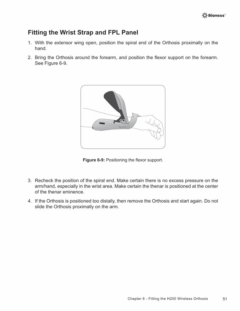
51Chapter 6 - Fitting the H200 Wireless Orthosis
Fitting the Wrist Strap and FPL Panel
1. With the extensor wing open, position the spiral end of the Orthosis proximally on the hand.
2. Bring the Orthosis around the forearm, and position the flexor support on the forearm. See Figure 6-9.
Figure 6-9: Positioning the flexor support.
3. Recheck the position of the spiral end. Make certain there is no excess pressure on the arm/hand, especially in the wrist area. Make certain the thenar is positioned at the center of the thenar eminence.
4. If the Orthosis is positioned too distally, then remove the Orthosis and start again. Do not slide the Orthosis proximally on the arm.
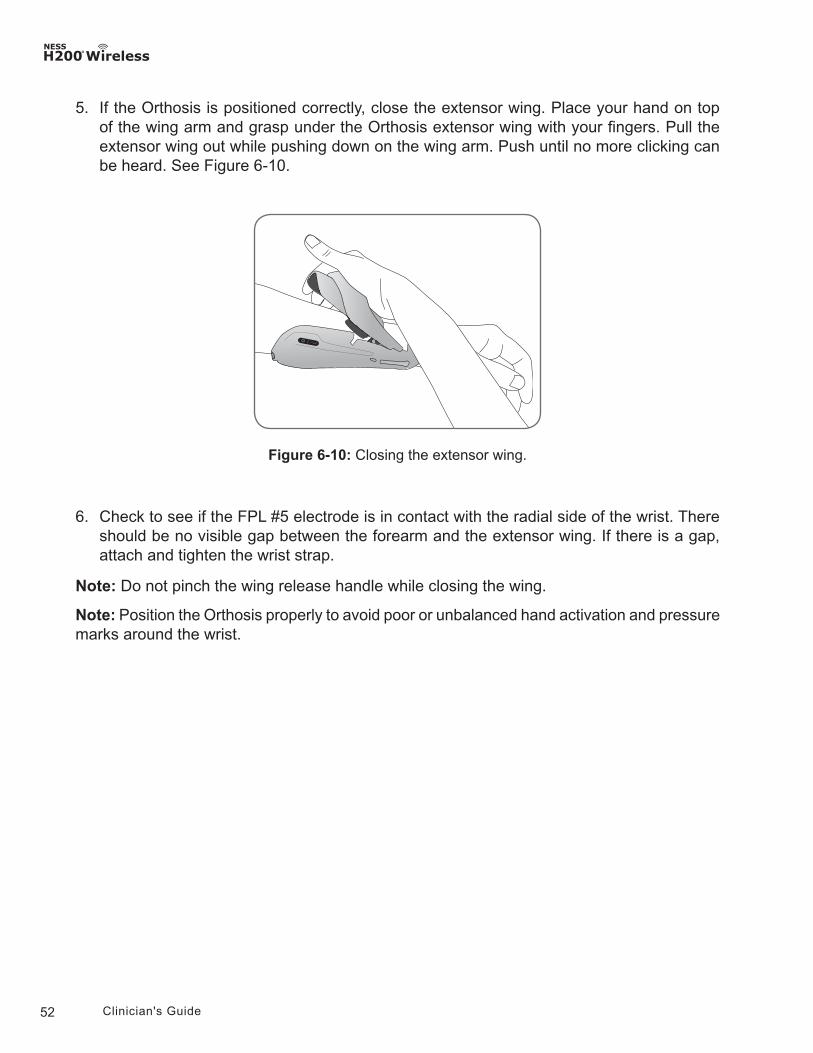
52 Clinician's Guide
5. If the Orthosis is positioned correctly, close the extensor wing. Place your hand on top of the wing arm and grasp under the Orthosis extensor wing with your fingers. Pull the extensor wing out while pushing down on the wing arm. Push until no more clicking can be heard. See Figure 6-10.
6. Check to see if the FPL #5 electrode is in contact with the radial side of the wrist. There should be no visible gap between the forearm and the extensor wing. If there is a gap, attach and tighten the wrist strap.
Note: Do not pinch the wing release handle while closing the wing.
Note: Position the Orthosis properly to avoid poor or unbalanced hand activation and pressure marks around the wrist.
Figure 6-10: Closing the extensor wing.
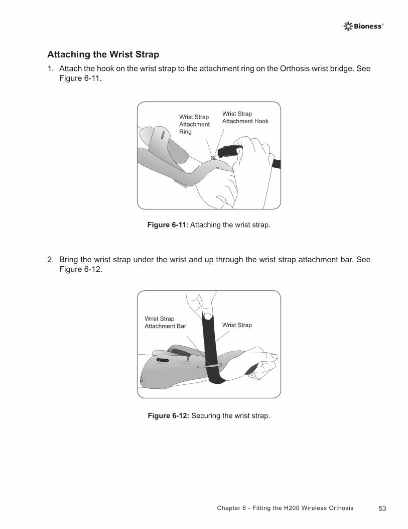
53Chapter 6 - Fitting the H200 Wireless Orthosis
Attaching the Wrist Strap
1. Attach the hook on the wrist strap to the attachment ring on the Orthosis wrist bridge. See Figure 6-11.
2. Bring the wrist strap under the wrist and up through the wrist strap attachment bar. See Figure 6-12.
Wrist Strap Attachment Ring
Wrist Strap Attachment Hook
Figure 6-11: Attaching the wrist strap.
Wrist Strap Attachment Bar Wrist Strap
Figure 6-12: Securing the wrist strap.
54 Clinician's Guide
3. Pull up on the wrist strap.
4. Bring the wrist strap down onto itself to fasten.
5. Check to see if the FPL #5 electrode is in contact with the radial side of the wrist. If there is a gap, tighten the wrist strap. If there is still a gap, attach the FPL panel.
Note: If the patient is feeling excessive pressure under the wrist strap or over the radial side of the wrist, loosen the wrist strap.
CAUTION: Do not pull down on the wrist strap. Pulling down on the wrist strap can break the wrist strap attachment bar.
CAUTION: Do not tighten the wrist strap so much that it interferes with blood flow to the hand.
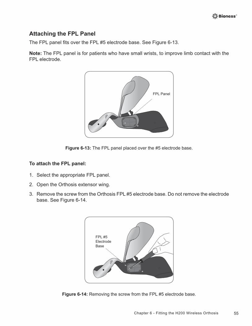
55Chapter 6 - Fitting the H200 Wireless Orthosis
Figure 6-14: Removing the screw from the FPL #5 electrode base.
FPL #5 Electrode Base
Attaching the FPL Panel
The FPL panel fits over the FPL #5 electrode base. See Figure 6-13.
Note: The FPL panel is for patients who have small wrists, to improve limb contact with the FPL electrode.
Figure 6-13: The FPL panel placed over the #5 electrode base.
FPL Panel
To attach the FPL panel:
1. Select the appropriate FPL panel.
2. Open the Orthosis extensor wing.
3. Remove the screw from the Orthosis FPL #5 electrode base. Do not remove the electrode base. See Figure 6-14.
56 Clinician's Guide
4. Place the FPL panel on top of the Orthosis FPL #5 electrode base.
5. Insert the FPL panel screw through the FPL panel electrode base and into the Orthosis FPL #5 electrode base and socket.
6. Tighten the screw.
CAUTION: Do not use the NESS H200 Wireless System without wetting and attaching the FPL #5 cloth electrode.
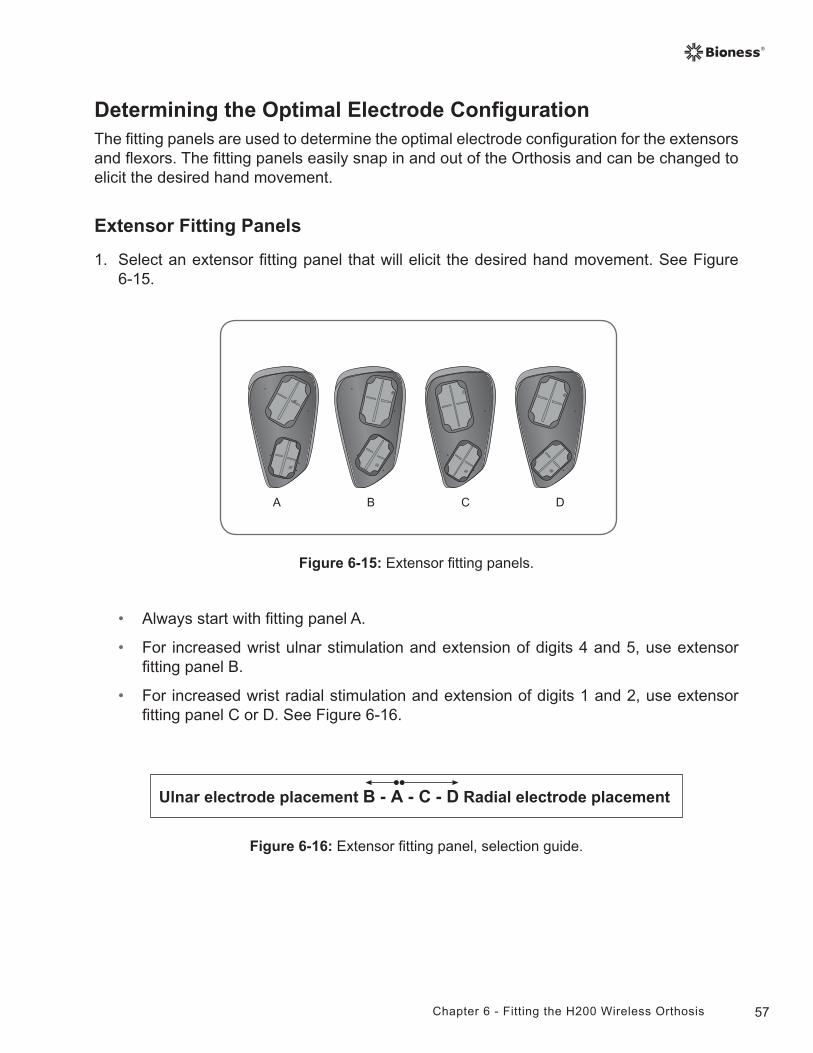
57Chapter 6 - Fitting the H200 Wireless Orthosis
Determining the Optimal Electrode ConfigurationThe fitting panels are used to determine the optimal electrode configuration for the extensors and flexors. The fitting panels easily snap in and out of the Orthosis and can be changed to elicit the desired hand movement.
Extensor Fitting Panels
1. Select an extensor fitting panel that will elicit the desired hand movement. See Figure 6-15.
Figure 6-15: Extensor fitting panels.
• Always start with fitting panel A.
• For increased wrist ulnar stimulation and extension of digits 4 and 5, use extensor fitting panel B.
• For increased wrist radial stimulation and extension of digits 1 and 2, use extensor fitting panel C or D. See Figure 6-16.
Ulnar electrode placement B - A - C - D Radial electrode placement
Figure 6-16: Extensor fitting panel, selection guide.
BA C D
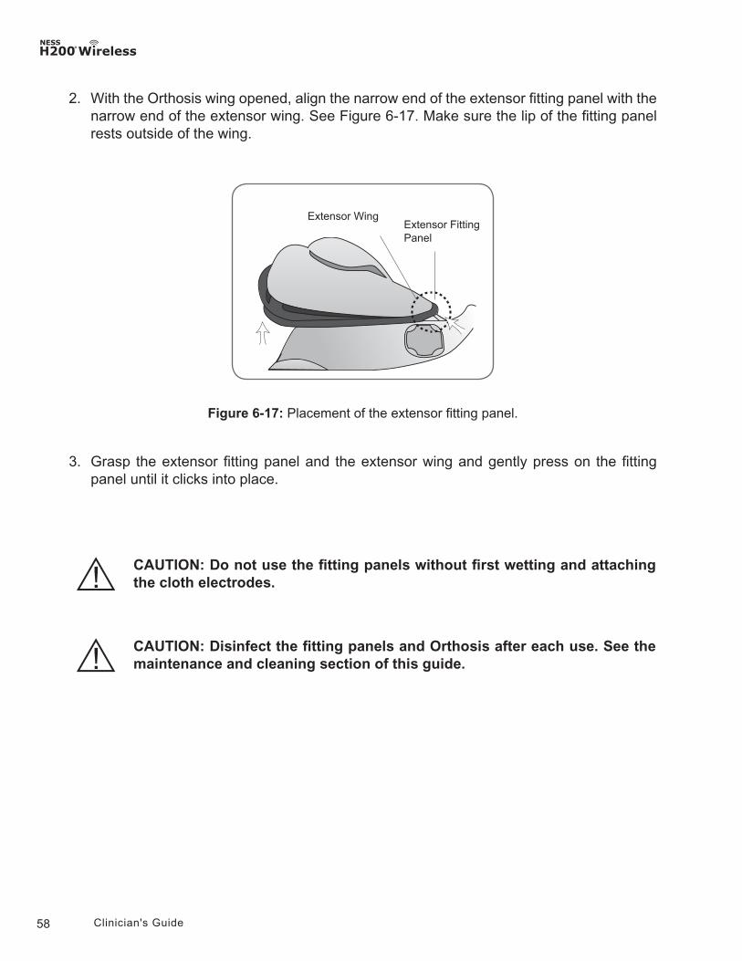
58 Clinician's Guide
Figure 6-17: Placement of the extensor fitting panel.
Extensor Fitting Panel
Extensor Wing
2. With the Orthosis wing opened, align the narrow end of the extensor fitting panel with the narrow end of the extensor wing. See Figure 6-17. Make sure the lip of the fitting panel rests outside of the wing.
3. Grasp the extensor fitting panel and the extensor wing and gently press on the fitting panel until it clicks into place.
CAUTION: Disinfect the fitting panels and Orthosis after each use. See the maintenance and cleaning section of this guide.
CAUTION: Do not use the fitting panels without first wetting and attaching the cloth electrodes.
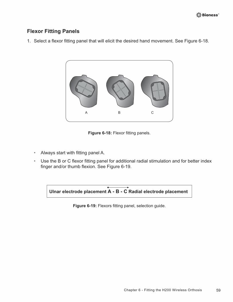
59Chapter 6 - Fitting the H200 Wireless Orthosis
Flexor Fitting Panels
1. Select a flexor fitting panel that will elicit the desired hand movement. See Figure 6-18.
• Always start with fitting panel A.
• Use the B or C flexor fitting panel for additional radial stimulation and for better index finger and/or thumb flexion. See Figure 6-19.
Figure 6-18: Flexor fitting panels.
Ulnar electrode placement A - B - C Radial electrode placement
Figure 6-19: Flexors fitting panel, selection guide.
BA C
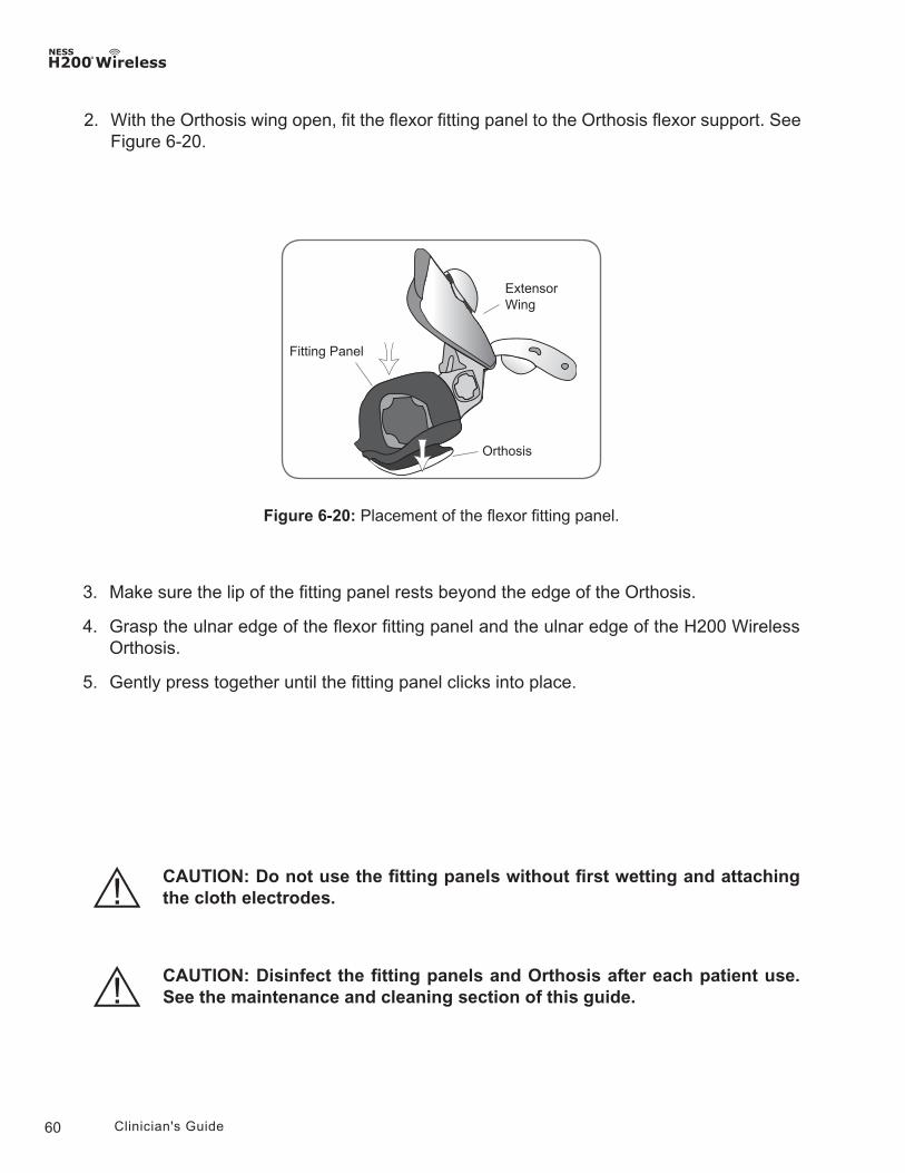
60 Clinician's Guide
2. With the Orthosis wing open, fit the flexor fitting panel to the Orthosis flexor support. See Figure 6-20.
Figure 6-20: Placement of the flexor fitting panel.
Orthosis
Extensor Wing
Fitting Panel
3. Make sure the lip of the fitting panel rests beyond the edge of the Orthosis.
4. Grasp the ulnar edge of the flexor fitting panel and the ulnar edge of the H200 Wireless Orthosis.
5. Gently press together until the fitting panel clicks into place.
CAUTION: Disinfect the fitting panels and Orthosis after each patient use. See the maintenance and cleaning section of this guide.
CAUTION: Do not use the fitting panels without first wetting and attaching the cloth electrodes.
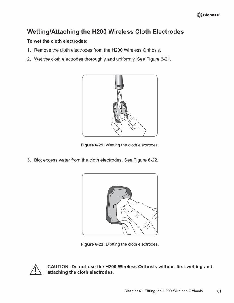
61Chapter 6 - Fitting the H200 Wireless Orthosis
Wetting/Attaching the H200 Wireless Cloth Electrodes
To wet the cloth electrodes:
1. Remove the cloth electrodes from the H200 Wireless Orthosis.
2. Wet the cloth electrodes thoroughly and uniformly. See Figure 6-21.
3. Blot excess water from the cloth electrodes. See Figure 6-22.
Figure 6-21: Wetting the cloth electrodes.
Figure 6-22: Blotting the cloth electrodes.
CAUTION: Do not use the H200 Wireless Orthosis without first wetting and attaching the cloth electrodes.
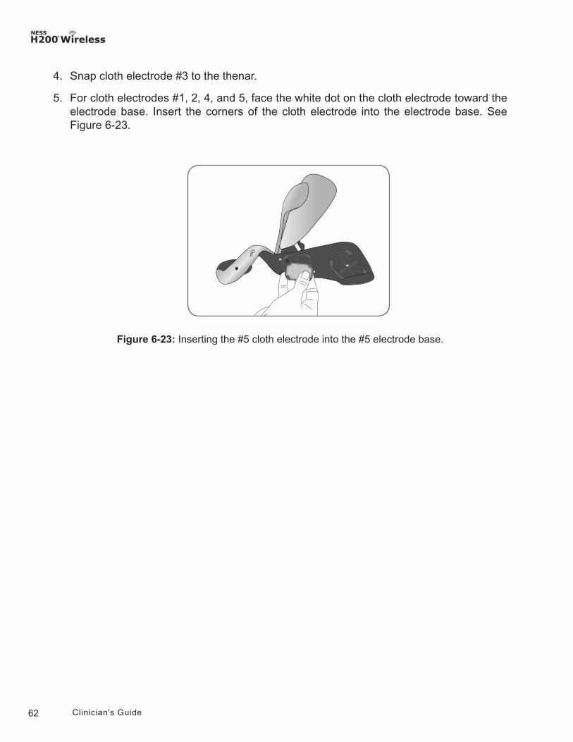
62 Clinician's Guide
4. Snap cloth electrode #3 to the thenar.
5. For cloth electrodes #1, 2, 4, and 5, face the white dot on the cloth electrode toward the electrode base. Insert the corners of the cloth electrode into the electrode base. See Figure 6-23.
Figure 6-23: Inserting the #5 cloth electrode into the #5 electrode base.
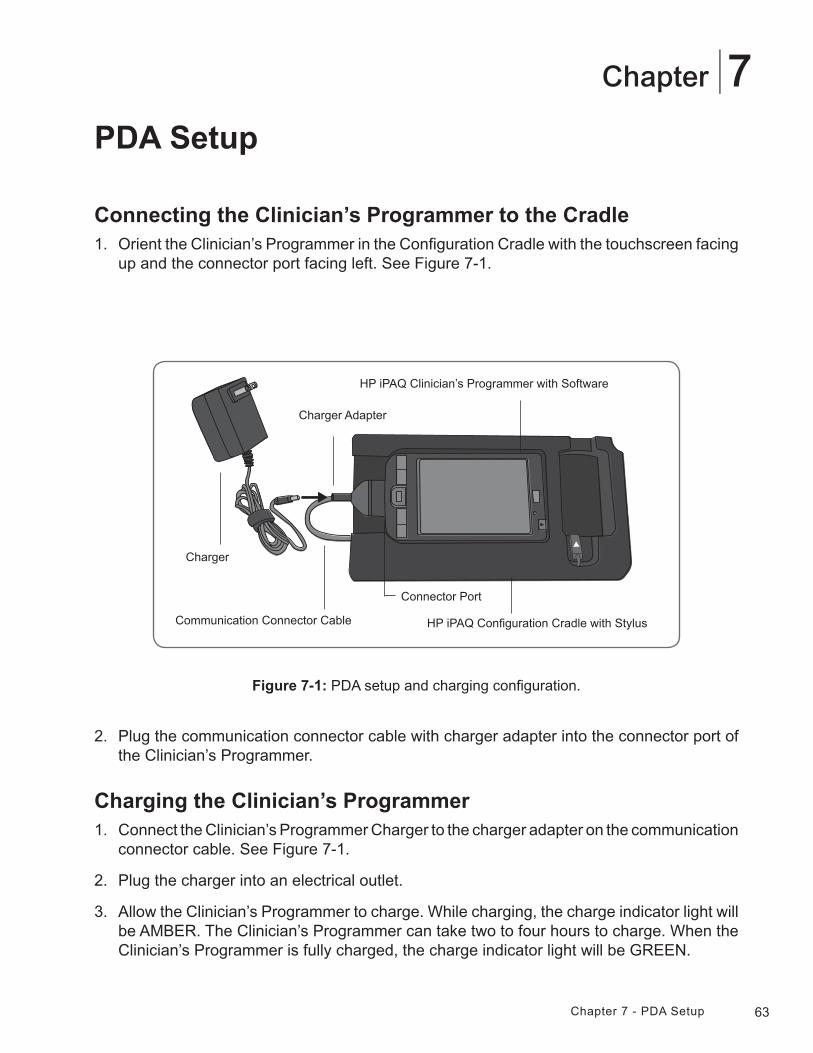
63Chapter 7 - PDA Setup
7Chapter
PDA Setup
Connecting the Clinician’s Programmer to the Cradle1. Orient the Clinician’s Programmer in the Configuration Cradle with the touchscreen facing
up and the connector port facing left. See Figure 7-1.
Charger
Communication Connector Cable
Charger Adapter
Connector Port
Figure 7-1: PDA setup and charging configuration.
2. Plug the communication connector cable with charger adapter into the connector port of the Clinician’s Programmer.
Charging the Clinician’s Programmer1. Connect the Clinician’s Programmer Charger to the charger adapter on the communication
connector cable. See Figure 7-1.
2. Plug the charger into an electrical outlet.
3. Allow the Clinician’s Programmer to charge. While charging, the charge indicator light will be AMBER. The Clinician’s Programmer can take two to four hours to charge. When the Clinician’s Programmer is fully charged, the charge indicator light will be GREEN.
HP iPAQ Clinician’s Programmer with Software
HP iPAQ Configuration Cradle with Stylus
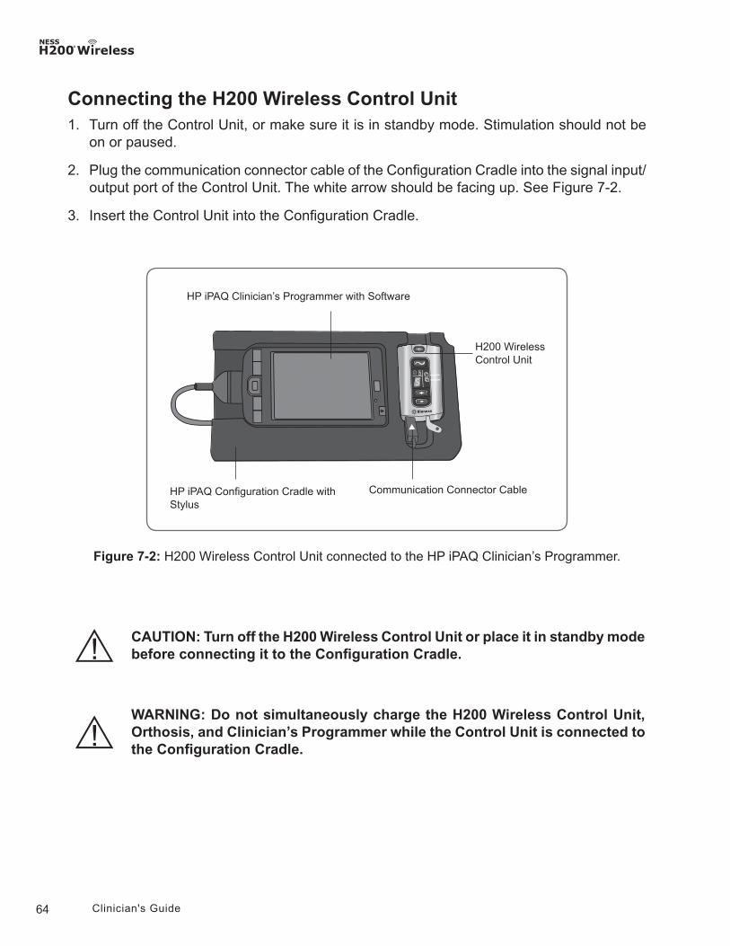
64 Clinician's Guide
Connecting the H200 Wireless Control Unit1. Turn off the Control Unit, or make sure it is in standby mode. Stimulation should not be
on or paused.
2. Plug the communication connector cable of the Configuration Cradle into the signal input/output port of the Control Unit. The white arrow should be facing up. See Figure 7-2.
3. Insert the Control Unit into the Configuration Cradle.
Figure 7-2: H200 Wireless Control Unit connected to the HP iPAQ Clinician’s Programmer.
HP iPAQ Clinician’s Programmer with Software
HP iPAQ Configuration Cradle with Stylus
H200 Wireless Control Unit
Communication Connector Cable
WARNING: Do not simultaneously charge the H200 Wireless Control Unit, Orthosis, and Clinician’s Programmer while the Control Unit is connected to the Configuration Cradle.
CAUTION: Turn off the H200 Wireless Control Unit or place it in standby mode before connecting it to the Configuration Cradle.
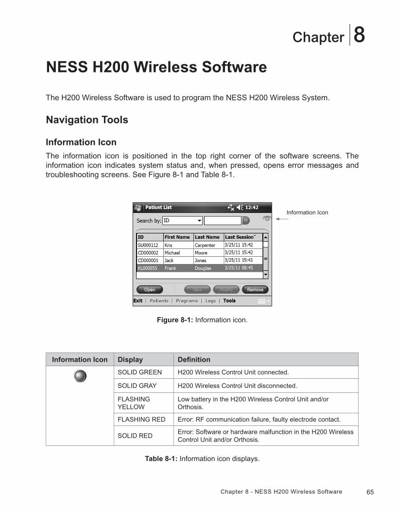
65Chapter 8 - NESS H200 Wireless Software
8Chapter
Information Icon Display Definition
SOLID GREEN H200 Wireless Control Unit connected.
SOLID GRAY H200 Wireless Control Unit disconnected.
FLASHING YELLOW
Low battery in the H200 Wireless Control Unit and/or Orthosis.
FLASHING RED Error: RF communication failure, faulty electrode contact.
SOLID REDError: Software or hardware malfunction in the H200 Wireless Control Unit and/or Orthosis.
Figure 8-1: Information icon.
Information Icon
NESS H200 Wireless Software
The H200 Wireless Software is used to program the NESS H200 Wireless System.
Navigation Tools
Information Icon
The information icon is positioned in the top right corner of the software screens. The information icon indicates system status and, when pressed, opens error messages and troubleshooting screens. See Figure 8-1 and Table 8-1.
Table 8-1: Information icon displays.
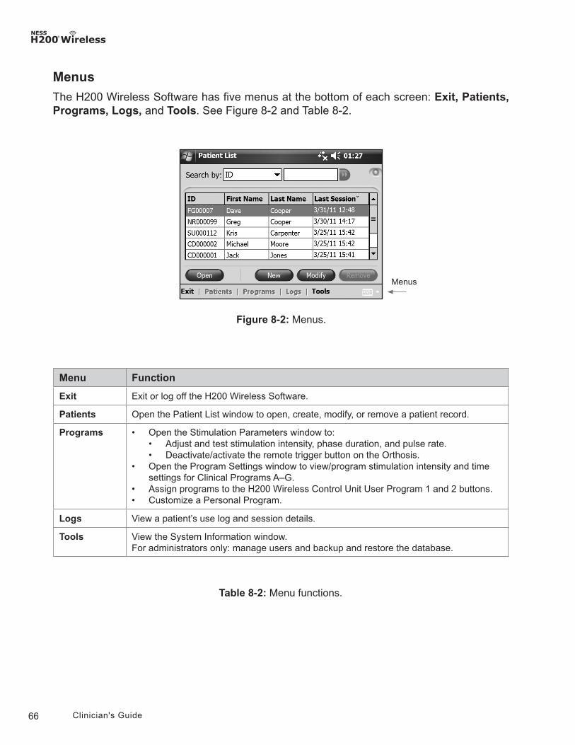
66 Clinician's Guide
Menu Function
Exit Exit or log off the H200 Wireless Software.
Patients Open the Patient List window to open, create, modify, or remove a patient record.
Programs • Open the Stimulation Parameters window to:• Adjust and test stimulation intensity, phase duration, and pulse rate.• Deactivate/activate the remote trigger button on the Orthosis.
• Open the Program Settings window to view/program stimulation intensity and time settings for Clinical Programs A–G.
• Assign programs to the H200 Wireless Control Unit User Program 1 and 2 buttons.• Customize a Personal Program.
Logs View a patient’s use log and session details.
Tools View the System Information window.For administrators only: manage users and backup and restore the database.
Table 8-2: Menu functions.
Figure 8-2: Menus.
Menus
Menus
The H200 Wireless Software has five menus at the bottom of each screen: Exit, Patients, Programs, Logs, and Tools. See Figure 8-2 and Table 8-2.
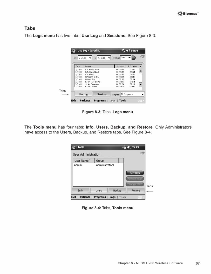
67Chapter 8 - NESS H200 Wireless Software
Tabs
The Logs menu has two tabs: Use Log and Sessions. See Figure 8-3.
Figure 8-4: Tabs, Tools menu.
Tabs
Figure 8-3: Tabs, Logs menu.
Tabs
The Tools menu has four tabs: Info, Users, Backup, and Restore. Only Administrators have access to the Users, Backup, and Restore tabs. See Figure 8-4.
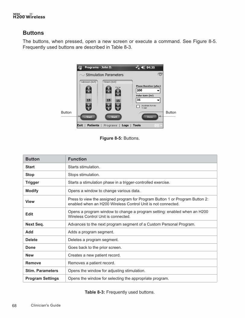
68 Clinician's Guide
Button Function
Start Starts stimulation.
Stop Stops stimulation.
Trigger Starts a stimulation phase in a trigger-controlled exercise.
Modify Opens a window to change various data.
ViewPress to view the assigned program for Program Button 1 or Program Button 2: enabled when an H200 Wireless Control Unit is not connected.
EditOpens a program window to change a program setting: enabled when an H200 Wireless Control Unit is connected.
Next Seq. Advances to the next program segment of a Custom Personal Program.
Add Adds a program segment.
Delete Deletes a program segment.
Done Goes back to the prior screen.
New Creates a new patient record.
Remove Removes a patient record.
Stim. Parameters Opens the window for adjusting stimulation.
Program Settings Opens the window for selecting the appropriate program.
Table 8-3: Frequently used buttons.
Buttons
The buttons, when pressed, open a new screen or execute a command. See Figure 8-5. Frequently used buttons are described in Table 8-3.
Figure 8-5: Buttons.
ButtonButton
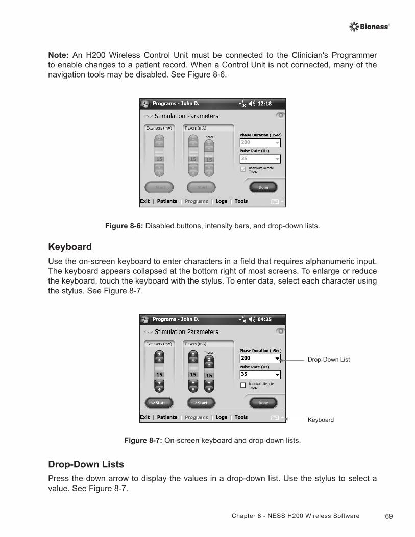
69Chapter 8 - NESS H200 Wireless Software
Note: An H200 Wireless Control Unit must be connected to the Clinician's Programmer to enable changes to a patient record. When a Control Unit is not connected, many of the navigation tools may be disabled. See Figure 8-6.
Figure 8-6: Disabled buttons, intensity bars, and drop-down lists.
Keyboard
Use the on-screen keyboard to enter characters in a field that requires alphanumeric input. The keyboard appears collapsed at the bottom right of most screens. To enlarge or reduce the keyboard, touch the keyboard with the stylus. To enter data, select each character using the stylus. See Figure 8-7.
Figure 8-7: On-screen keyboard and drop-down lists.
Drop-Down List
Keyboard
Drop-Down Lists
Press the down arrow to display the values in a drop-down list. Use the stylus to select a value. See Figure 8-7.
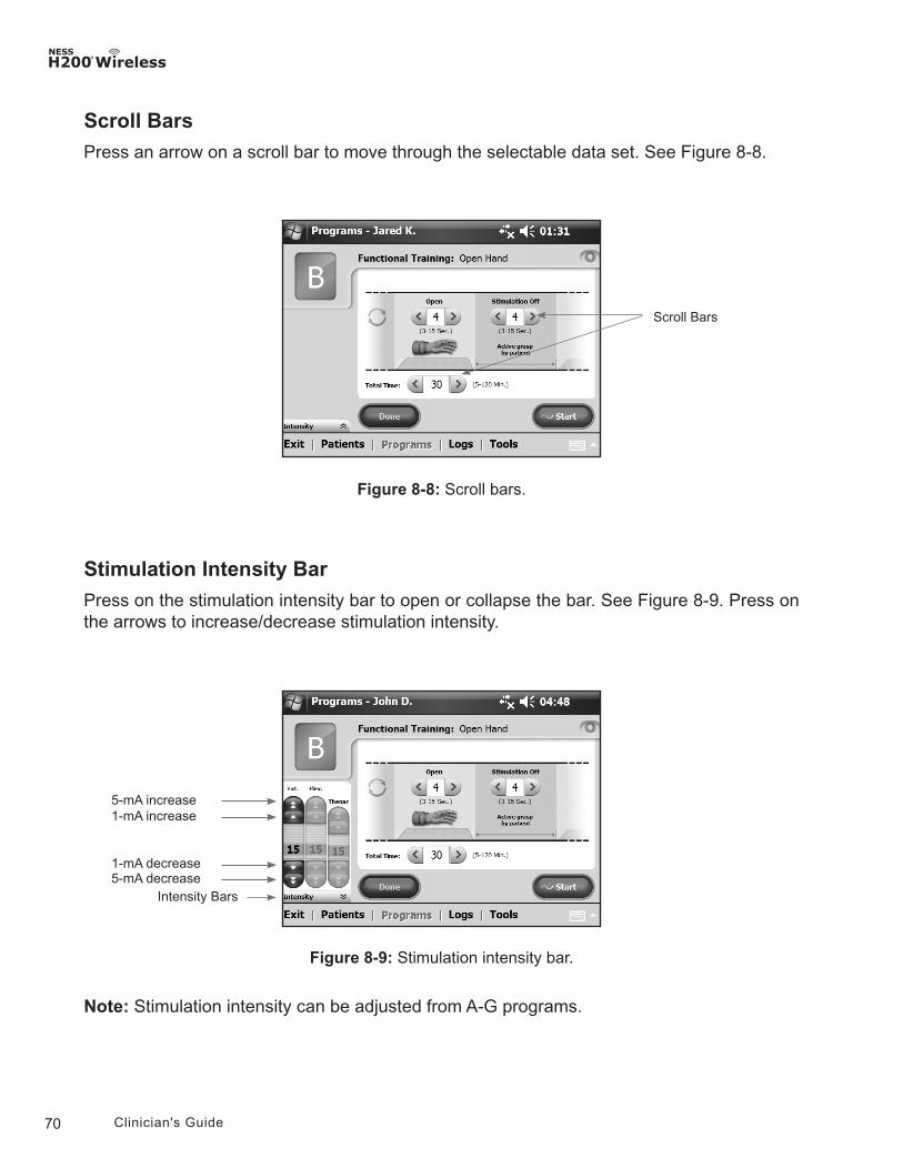
70 Clinician's Guide
Scroll Bars
Press an arrow on a scroll bar to move through the selectable data set. See Figure 8-8.
Stimulation Intensity Bar
Press on the stimulation intensity bar to open or collapse the bar. See Figure 8-9. Press on the arrows to increase/decrease stimulation intensity.
Figure 8-9: Stimulation intensity bar.
Intensity Bars
5-mA increase1-mA increase
5-mA decrease1-mA decrease
Figure 8-8: Scroll bars.
Scroll Bars
Note: Stimulation intensity can be adjusted from A-G programs.
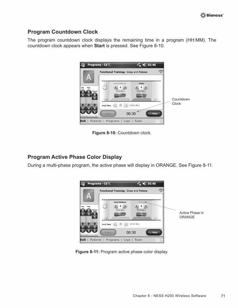
71Chapter 8 - NESS H200 Wireless Software
Program Countdown Clock
The program countdown clock displays the remaining time in a program (HH:MM). The countdown clock appears when Start is pressed. See Figure 8-10.
Figure 8-10: Countdown clock.
Countdown Clock
Figure 8-11: Program active phase color display.
Program Active Phase Color Display
During a multi-phase program, the active phase will display in ORANGE. See Figure 8-11.
Active Phase in ORANGE
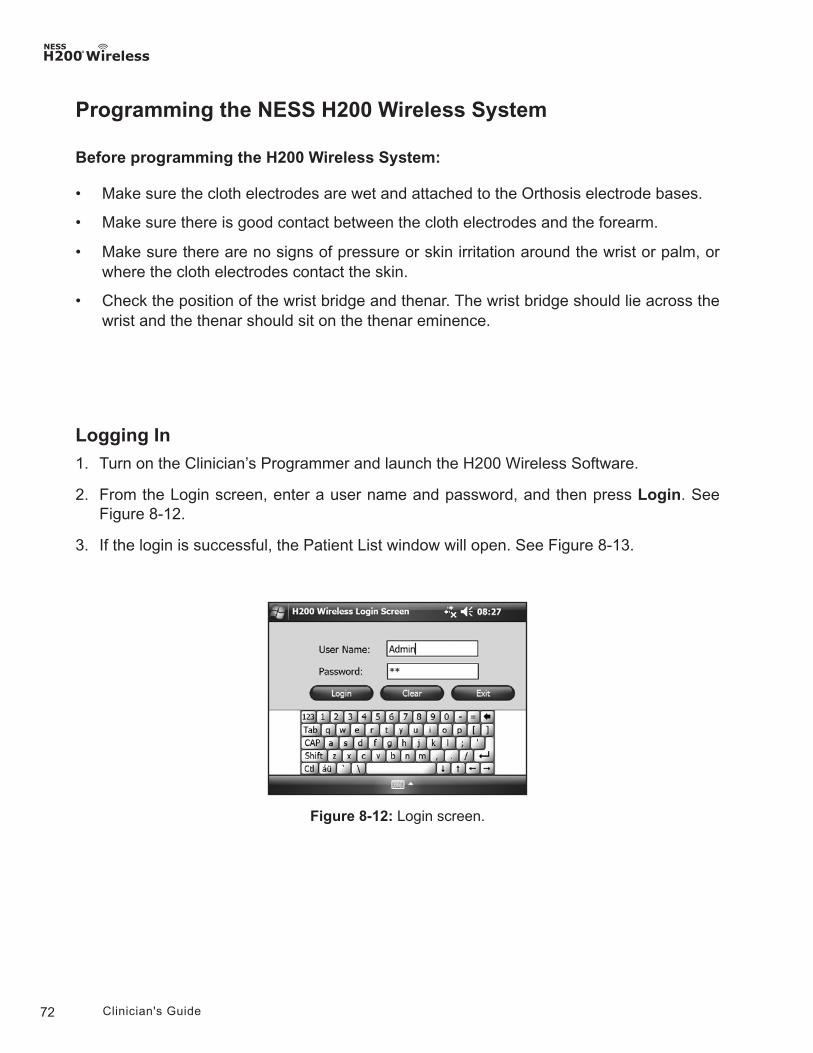
72 Clinician's Guide
Programming the NESS H200 Wireless System
Before programming the H200 Wireless System:
• Make sure the cloth electrodes are wet and attached to the Orthosis electrode bases.
• Make sure there is good contact between the cloth electrodes and the forearm.
• Make sure there are no signs of pressure or skin irritation around the wrist or palm, or where the cloth electrodes contact the skin.
• Check the position of the wrist bridge and thenar. The wrist bridge should lie across the wrist and the thenar should sit on the thenar eminence.
Figure 8-12: Login screen.
Logging In
1. Turn on the Clinician’s Programmer and launch the H200 Wireless Software.
2. From the Login screen, enter a user name and password, and then press Login. See Figure 8-12.
3. If the login is successful, the Patient List window will open. See Figure 8-13.
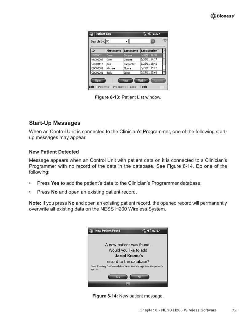
73Chapter 8 - NESS H200 Wireless Software
Figure 8-13: Patient List window.
Start-Up Messages
When an Control Unit is connected to the Clinician’s Programmer, one of the following start-up messages may appear.
New Patient Detected
Message appears when an Control Unit with patient data on it is connected to a Clinician’s Programmer with no record of the data in the database. See Figure 8-14. Do one of the following:
• Press Yes to add the patient’s data to the Clinician’s Programmer database.
• Press No and open an existing patient record.
Note: If you press No and open an existing patient record, the opened record will permanently overwrite all existing data on the NESS H200 Wireless System.
Figure 8-14: New patient message.
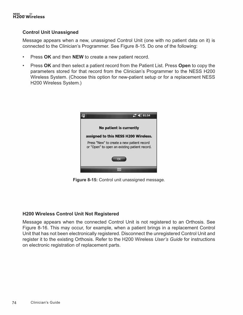
74 Clinician's Guide
Control Unit Unassigned
Message appears when a new, unassigned Control Unit (one with no patient data on it) is connected to the Clinician’s Programmer. See Figure 8-15. Do one of the following:
• Press OK and then NEW to create a new patient record.
• Press OK and then select a patient record from the Patient List. Press Open to copy the parameters stored for that record from the Clinician’s Programmer to the NESS H200 Wireless System. (Choose this option for new-patient setup or for a replacement NESS H200 Wireless System.)
H200 Wireless Control Unit Not Registered
Message appears when the connected Control Unit is not registered to an Orthosis. See Figure 8-16. This may occur, for example, when a patient brings in a replacement Control Unit that has not been electronically registered. Disconnect the unregistered Control Unit and register it to the existing Orthosis. Refer to the H200 Wireless User’s Guide for instructions on electronic registration of replacement parts.
Figure 8-15: Control unit unassigned message.
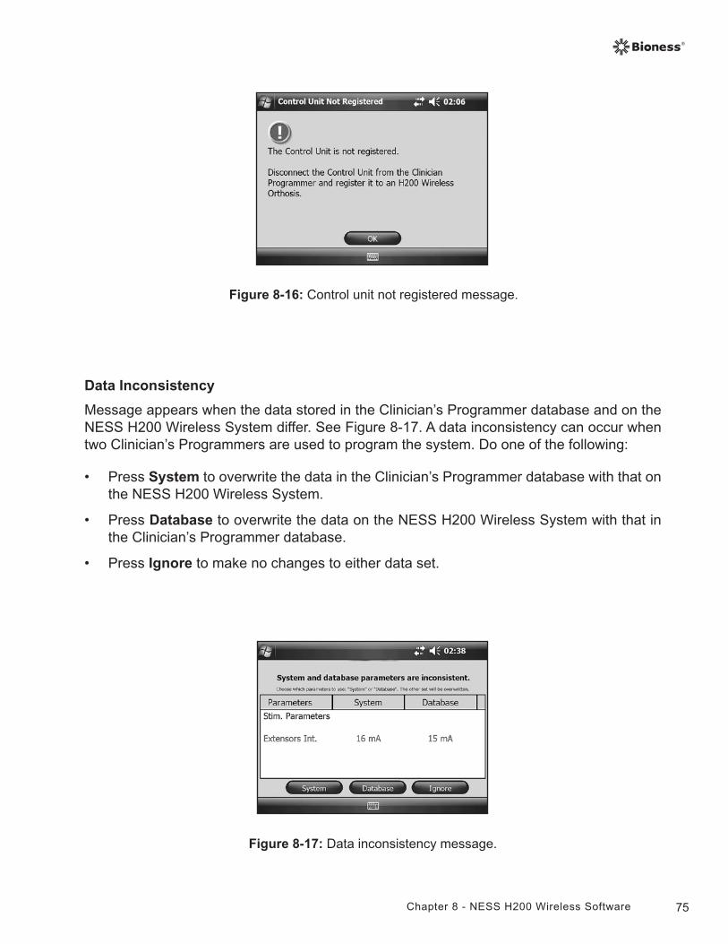
75Chapter 8 - NESS H200 Wireless Software
Figure 8-16: Control unit not registered message.
Data Inconsistency
Message appears when the data stored in the Clinician’s Programmer database and on the NESS H200 Wireless System differ. See Figure 8-17. A data inconsistency can occur when two Clinician’s Programmers are used to program the system. Do one of the following:
• Press System to overwrite the data in the Clinician’s Programmer database with that on the NESS H200 Wireless System.
• Press Database to overwrite the data on the NESS H200 Wireless System with that in the Clinician’s Programmer database.
• Press Ignore to make no changes to either data set.
Figure 8-17: Data inconsistency message.
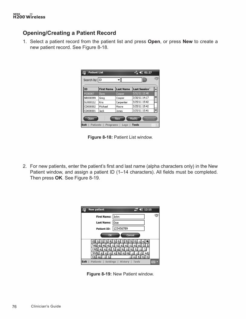
76 Clinician's Guide
Opening/Creating a Patient Record
1. Select a patient record from the patient list and press Open, or press New to create a new patient record. See Figure 8-18.
Figure 8-18: Patient List window.
Figure 8-19: New Patient window.
2. For new patients, enter the patient’s first and last name (alpha characters only) in the New Patient window, and assign a patient ID (1–14 characters). All fields must be completed. Then press OK. See Figure 8-19.
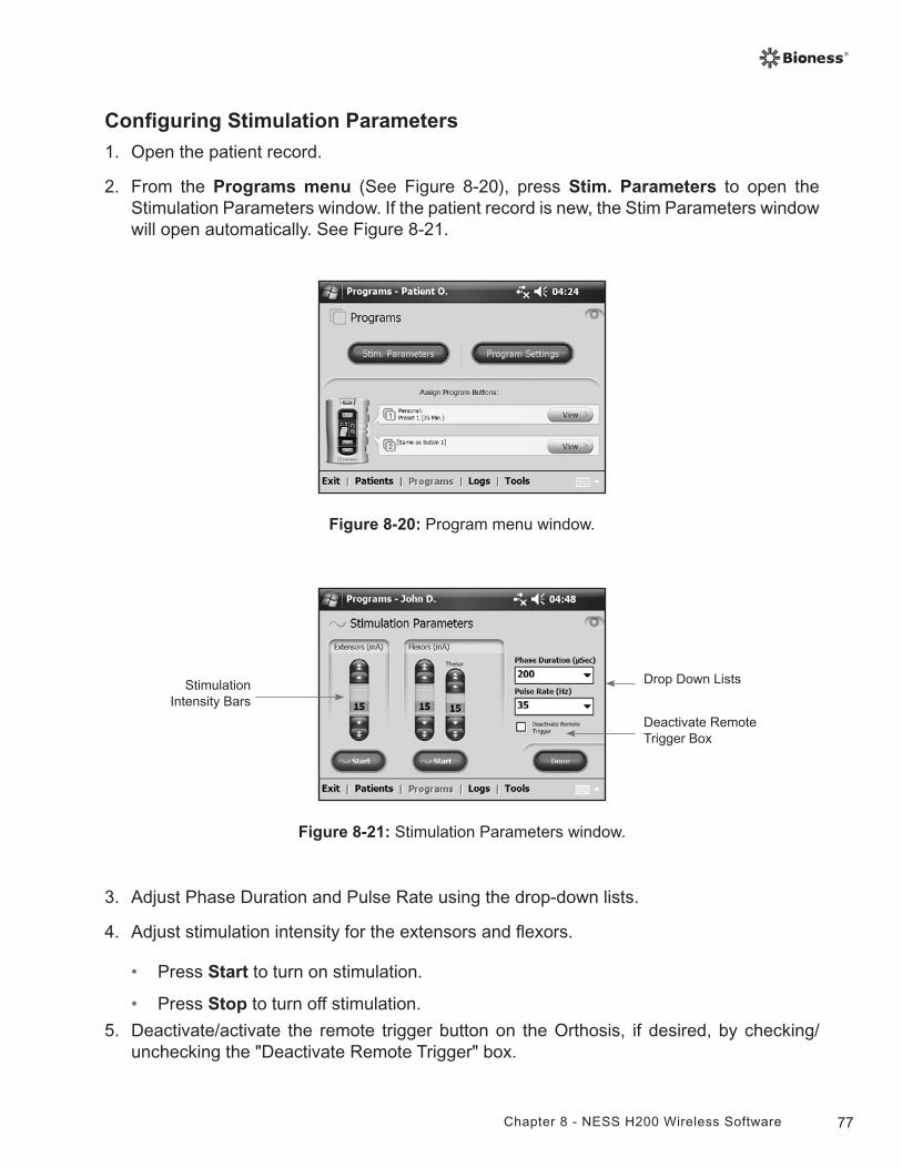
77Chapter 8 - NESS H200 Wireless Software
Configuring Stimulation Parameters
1. Open the patient record.
2. From the Programs menu (See Figure 8-20), press Stim. Parameters to open the Stimulation Parameters window. If the patient record is new, the Stim Parameters window will open automatically. See Figure 8-21.
Figure 8-21: Stimulation Parameters window.
Deactivate Remote Trigger Box
Stimulation Intensity Bars
Drop Down Lists
3. Adjust Phase Duration and Pulse Rate using the drop-down lists.
4. Adjust stimulation intensity for the extensors and flexors.
• Press Start to turn on stimulation.
• Press Stop to turn off stimulation.
5. Deactivate/activate the remote trigger button on the Orthosis, if desired, by checking/unchecking the "Deactivate Remote Trigger" box.
Figure 8-20: Program menu window.
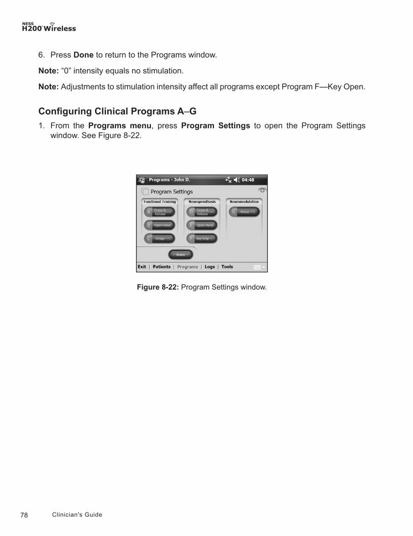
78 Clinician's Guide
6. Press Done to return to the Programs window.
Note: “0” intensity equals no stimulation.
Note: Adjustments to stimulation intensity affect all programs except Program F—Key Open.
Configuring Clinical Programs A–G
1. From the Programs menu, press Program Settings to open the Program Settings window. See Figure 8-22.
Figure 8-22: Program Settings window.
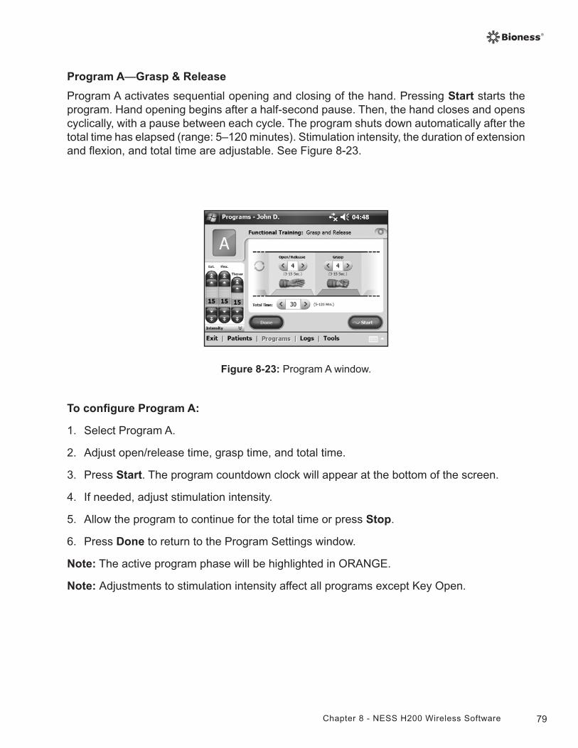
79Chapter 8 - NESS H200 Wireless Software
Program A—Grasp & Release
Program A activates sequential opening and closing of the hand. Pressing Start starts the program. Hand opening begins after a half-second pause. Then, the hand closes and opens cyclically, with a pause between each cycle. The program shuts down automatically after the total time has elapsed (range: 5–120 minutes). Stimulation intensity, the duration of extension and flexion, and total time are adjustable. See Figure 8-23.
Figure 8-23: Program A window.
To configure Program A:
1. Select Program A.
2. Adjust open/release time, grasp time, and total time.
3. Press Start. The program countdown clock will appear at the bottom of the screen.
4. If needed, adjust stimulation intensity.
5. Allow the program to continue for the total time or press Stop.
6. Press Done to return to the Program Settings window.
Note: The active program phase will be highlighted in ORANGE.
Note: Adjustments to stimulation intensity affect all programs except Key Open.
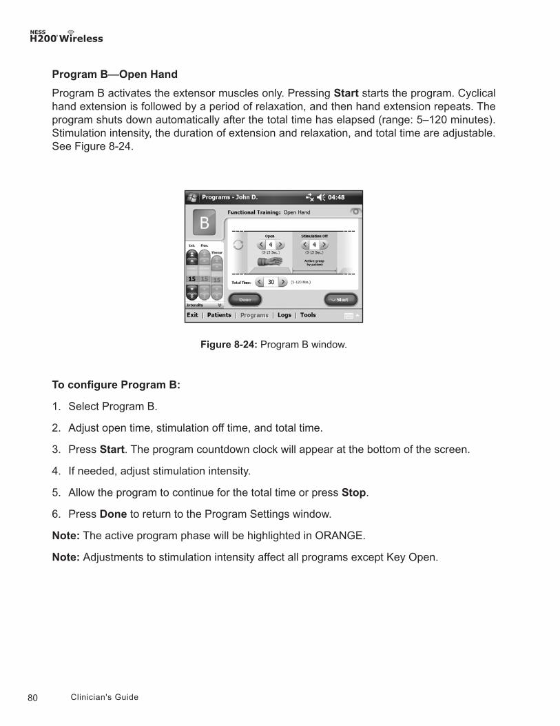
80 Clinician's Guide
Figure 8-24: Program B window.
Program B—Open Hand
Program B activates the extensor muscles only. Pressing Start starts the program. Cyclical hand extension is followed by a period of relaxation, and then hand extension repeats. The program shuts down automatically after the total time has elapsed (range: 5–120 minutes). Stimulation intensity, the duration of extension and relaxation, and total time are adjustable. See Figure 8-24.
To configure Program B:
1. Select Program B.
2. Adjust open time, stimulation off time, and total time.
3. Press Start. The program countdown clock will appear at the bottom of the screen.
4. If needed, adjust stimulation intensity.
5. Allow the program to continue for the total time or press Stop.
6. Press Done to return to the Program Settings window.
Note: The active program phase will be highlighted in ORANGE.
Note: Adjustments to stimulation intensity affect all programs except Key Open.
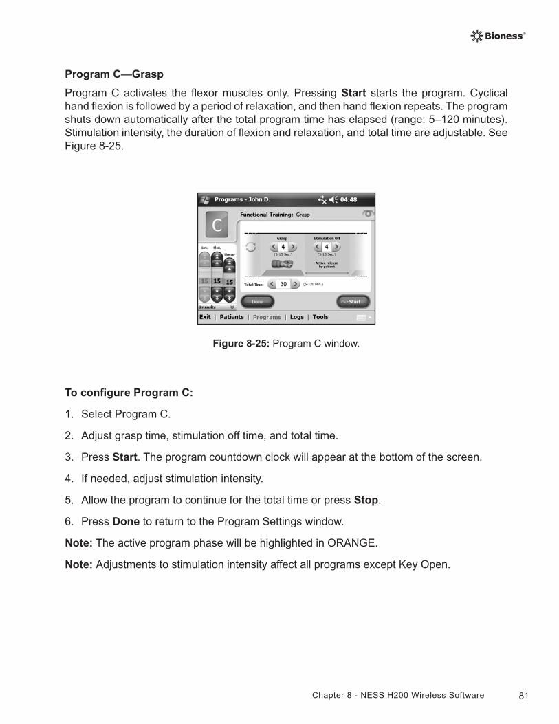
81Chapter 8 - NESS H200 Wireless Software
Figure 8-25: Program C window.
Program C—Grasp
Program C activates the flexor muscles only. Pressing Start starts the program. Cyclical hand flexion is followed by a period of relaxation, and then hand flexion repeats. The program shuts down automatically after the total program time has elapsed (range: 5–120 minutes). Stimulation intensity, the duration of flexion and relaxation, and total time are adjustable. See Figure 8-25.
To configure Program C:
1. Select Program C.
2. Adjust grasp time, stimulation off time, and total time.
3. Press Start. The program countdown clock will appear at the bottom of the screen.
4. If needed, adjust stimulation intensity.
5. Allow the program to continue for the total time or press Stop.
6. Press Done to return to the Program Settings window.
Note: The active program phase will be highlighted in ORANGE.
Note: Adjustments to stimulation intensity affect all programs except Key Open.
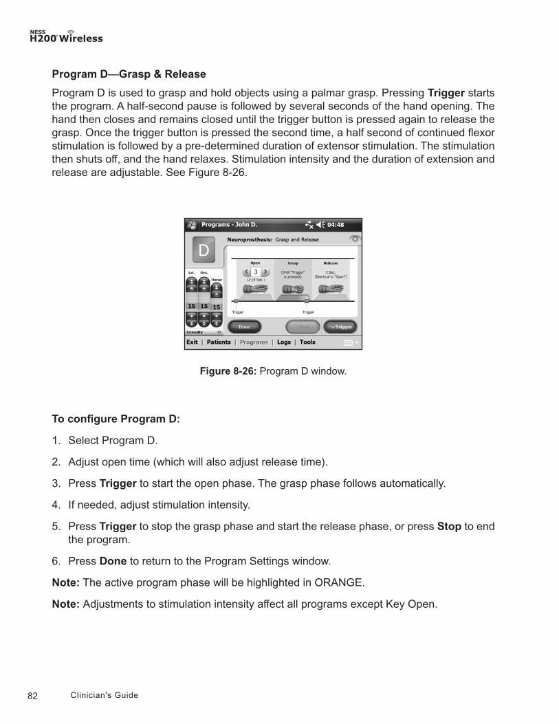
82 Clinician's Guide
Program D—Grasp & Release
Program D is used to grasp and hold objects using a palmar grasp. Pressing Trigger starts the program. A half-second pause is followed by several seconds of the hand opening. The hand then closes and remains closed until the trigger button is pressed again to release the grasp. Once the trigger button is pressed the second time, a half second of continued flexor stimulation is followed by a pre-determined duration of extensor stimulation. The stimulation then shuts off, and the hand relaxes. Stimulation intensity and the duration of extension and release are adjustable. See Figure 8-26.
Figure 8-26: Program D window.
To configure Program D:
1. Select Program D.
2. Adjust open time (which will also adjust release time).
3. Press Trigger to start the open phase. The grasp phase follows automatically.
4. If needed, adjust stimulation intensity.
5. Press Trigger to stop the grasp phase and start the release phase, or press Stop to end the program.
6. Press Done to return to the Program Settings window.
Note: The active program phase will be highlighted in ORANGE.
Note: Adjustments to stimulation intensity affect all programs except Key Open.
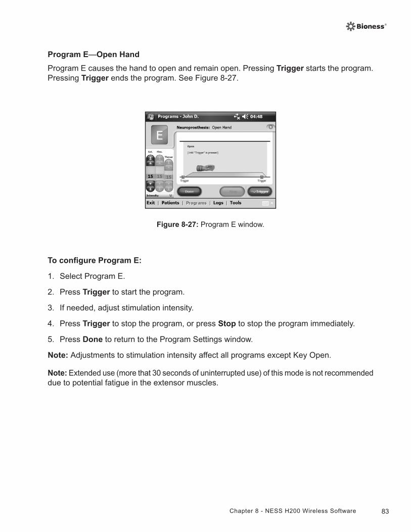
83Chapter 8 - NESS H200 Wireless Software
Program E—Open Hand
Program E causes the hand to open and remain open. Pressing Trigger starts the program. Pressing Trigger ends the program. See Figure 8-27.
Figure 8-27: Program E window.
To configure Program E:
1. Select Program E.
2. Press Trigger to start the program.
3. If needed, adjust stimulation intensity.
4. Press Trigger to stop the program, or press Stop to stop the program immediately.
5. Press Done to return to the Program Settings window.
Note: Adjustments to stimulation intensity affect all programs except Key Open.
Note: Extended use (more that 30 seconds of uninterrupted use) of this mode is not recommended due to potential fatigue in the extensor muscles.
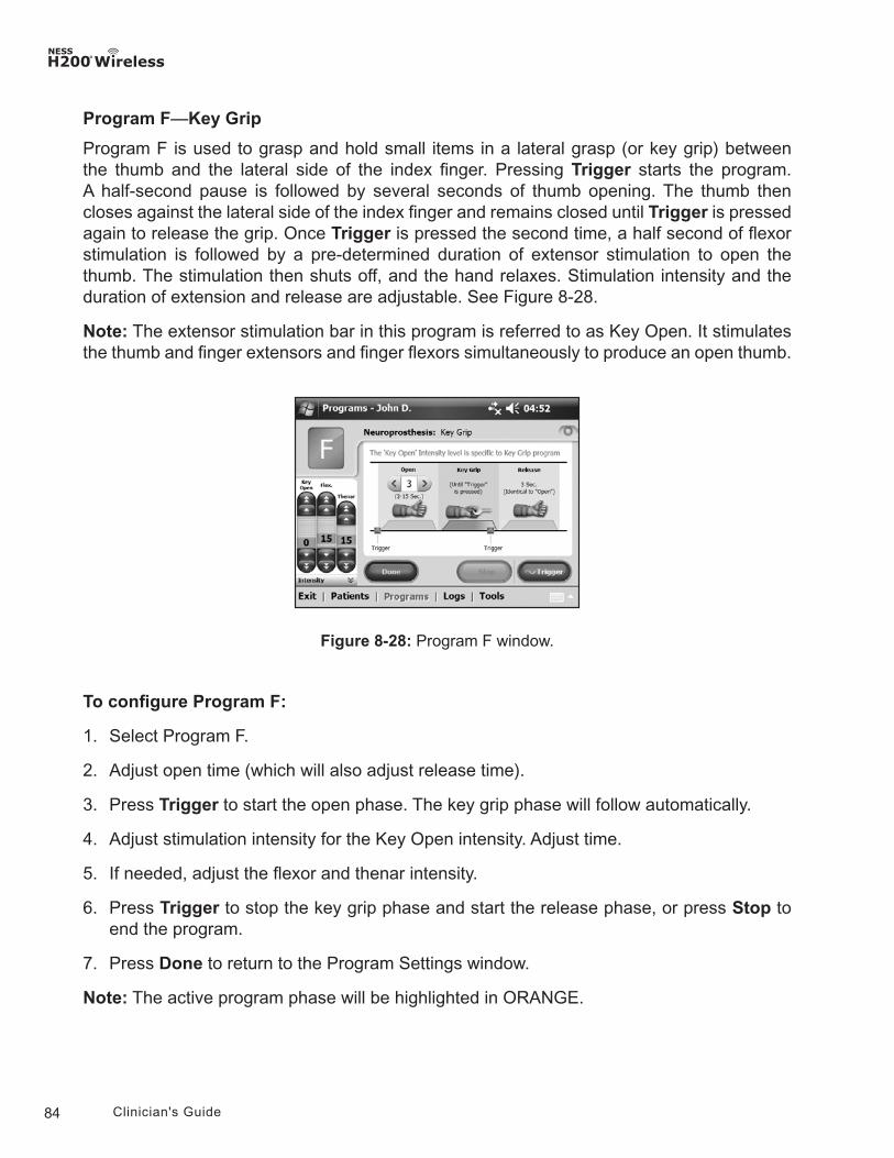
84 Clinician's Guide
Program F—Key Grip
Program F is used to grasp and hold small items in a lateral grasp (or key grip) between the thumb and the lateral side of the index finger. Pressing Trigger starts the program. A half-second pause is followed by several seconds of thumb opening. The thumb then closes against the lateral side of the index finger and remains closed until Trigger is pressed again to release the grip. Once Trigger is pressed the second time, a half second of flexor stimulation is followed by a pre-determined duration of extensor stimulation to open the thumb. The stimulation then shuts off, and the hand relaxes. Stimulation intensity and the duration of extension and release are adjustable. See Figure 8-28.
Note: The extensor stimulation bar in this program is referred to as Key Open. It stimulates the thumb and finger extensors and finger flexors simultaneously to produce an open thumb.
Figure 8-28: Program F window.
To configure Program F:
1. Select Program F.
2. Adjust open time (which will also adjust release time).
3. Press Trigger to start the open phase. The key grip phase will follow automatically.
4. Adjust stimulation intensity for the Key Open intensity. Adjust time.
5. If needed, adjust the flexor and thenar intensity.
6. Press Trigger to stop the key grip phase and start the release phase, or press Stop to end the program.
7. Press Done to return to the Program Settings window.
Note: The active program phase will be highlighted in ORANGE.
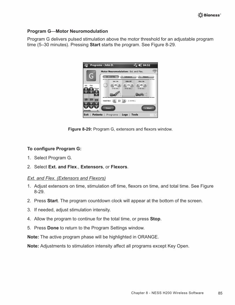
85Chapter 8 - NESS H200 Wireless Software
Program G—Motor Neuromodulation
Program G delivers pulsed stimulation above the motor threshold for an adjustable program time (5–30 minutes). Pressing Start starts the program. See Figure 8-29.
Figure 8-29: Program G, extensors and flexors window.
To configure Program G:
1. Select Program G.
2. Select Ext. and Flex., Extensors, or Flexors.
Ext. and Flex. (Extensors and Flexors)
1. Adjust extensors on time, stimulation off time, flexors on time, and total time. See Figure 8-29.
2. Press Start. The program countdown clock will appear at the bottom of the screen.
3. If needed, adjust stimulation intensity.
4. Allow the program to continue for the total time, or press Stop.
5. Press Done to return to the Program Settings window.
Note: The active program phase will be highlighted in ORANGE.
Note: Adjustments to stimulation intensity affect all programs except Key Open.
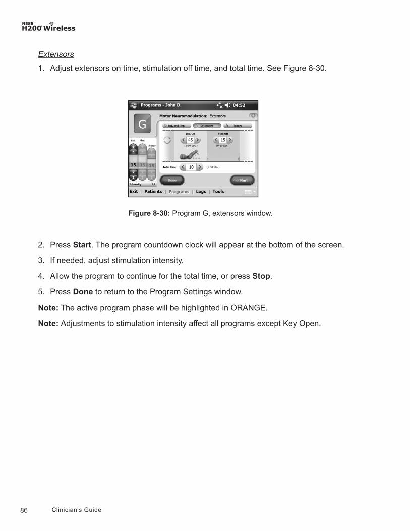
86 Clinician's Guide
Figure 8-30: Program G, extensors window.
Extensors
1. Adjust extensors on time, stimulation off time, and total time. See Figure 8-30.
2. Press Start. The program countdown clock will appear at the bottom of the screen.
3. If needed, adjust stimulation intensity.
4. Allow the program to continue for the total time, or press Stop.
5. Press Done to return to the Program Settings window.
Note: The active program phase will be highlighted in ORANGE.
Note: Adjustments to stimulation intensity affect all programs except Key Open.
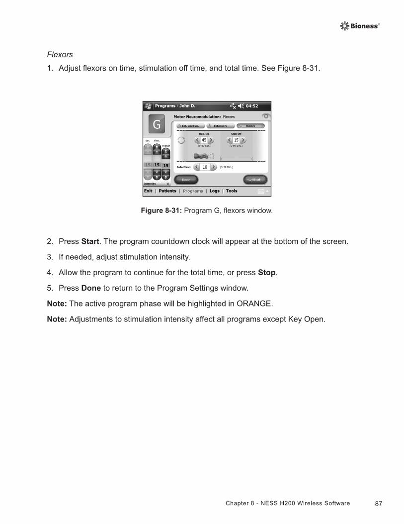
87Chapter 8 - NESS H200 Wireless Software
Figure 8-31: Program G, flexors window.
Flexors
1. Adjust flexors on time, stimulation off time, and total time. See Figure 8-31.
2. Press Start. The program countdown clock will appear at the bottom of the screen.
3. If needed, adjust stimulation intensity.
4. Allow the program to continue for the total time, or press Stop.
5. Press Done to return to the Program Settings window.
Note: The active program phase will be highlighted in ORANGE.
Note: Adjustments to stimulation intensity affect all programs except Key Open.
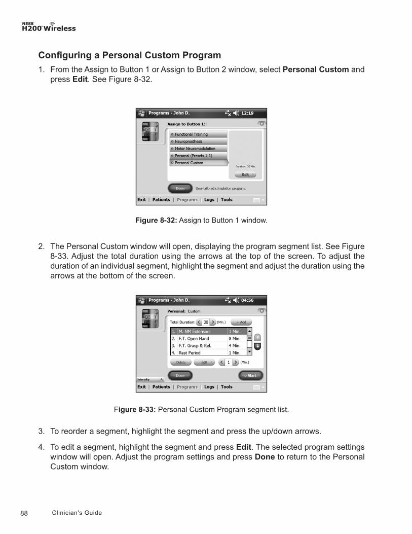
88 Clinician's Guide
Figure 8-32: Assign to Button 1 window.
2. The Personal Custom window will open, displaying the program segment list. See Figure 8-33. Adjust the total duration using the arrows at the top of the screen. To adjust the duration of an individual segment, highlight the segment and adjust the duration using the arrows at the bottom of the screen.
Configuring a Personal Custom Program
1. From the Assign to Button 1 or Assign to Button 2 window, select Personal Custom and press Edit. See Figure 8-32.
3. To reorder a segment, highlight the segment and press the up/down arrows.
4. To edit a segment, highlight the segment and press Edit. The selected program settings window will open. Adjust the program settings and press Done to return to the Personal Custom window.
Figure 8-33: Personal Custom Program segment list.
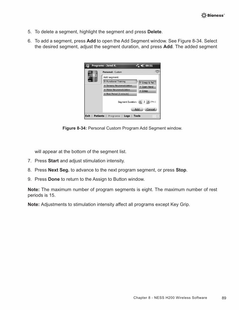
89Chapter 8 - NESS H200 Wireless Software
5. To delete a segment, highlight the segment and press Delete.
6. To add a segment, press Add to open the Add Segment window. See Figure 8-34. Select the desired segment, adjust the segment duration, and press Add. The added segment
Figure 8-34: Personal Custom Program Add Segment window.
will appear at the bottom of the segment list.
7. Press Start and adjust stimulation intensity.
8. Press Next Seg. to advance to the next program segment, or press Stop.
9. Press Done to return to the Assign to Button window.
Note: The maximum number of program segments is eight. The maximum number of rest periods is 15.
Note: Adjustments to stimulation intensity affect all programs except Key Grip.
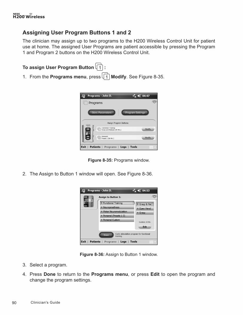
90 Clinician's Guide
Assigning User Program Buttons 1 and 2
The clinician may assign up to two programs to the H200 Wireless Control Unit for patient use at home. The assigned User Programs are patient accessible by pressing the Program 1 and Program 2 buttons on the H200 Wireless Control Unit.
To assign User Program Button :
1. From the Programs menu, press Modify. See Figure 8-35.
Figure 8-35: Programs window.
2. The Assign to Button 1 window will open. See Figure 8-36.
Figure 8-36: Assign to Button 1 window.
3. Select a program.
4. Press Done to return to the Programs menu, or press Edit to open the program and change the program settings.
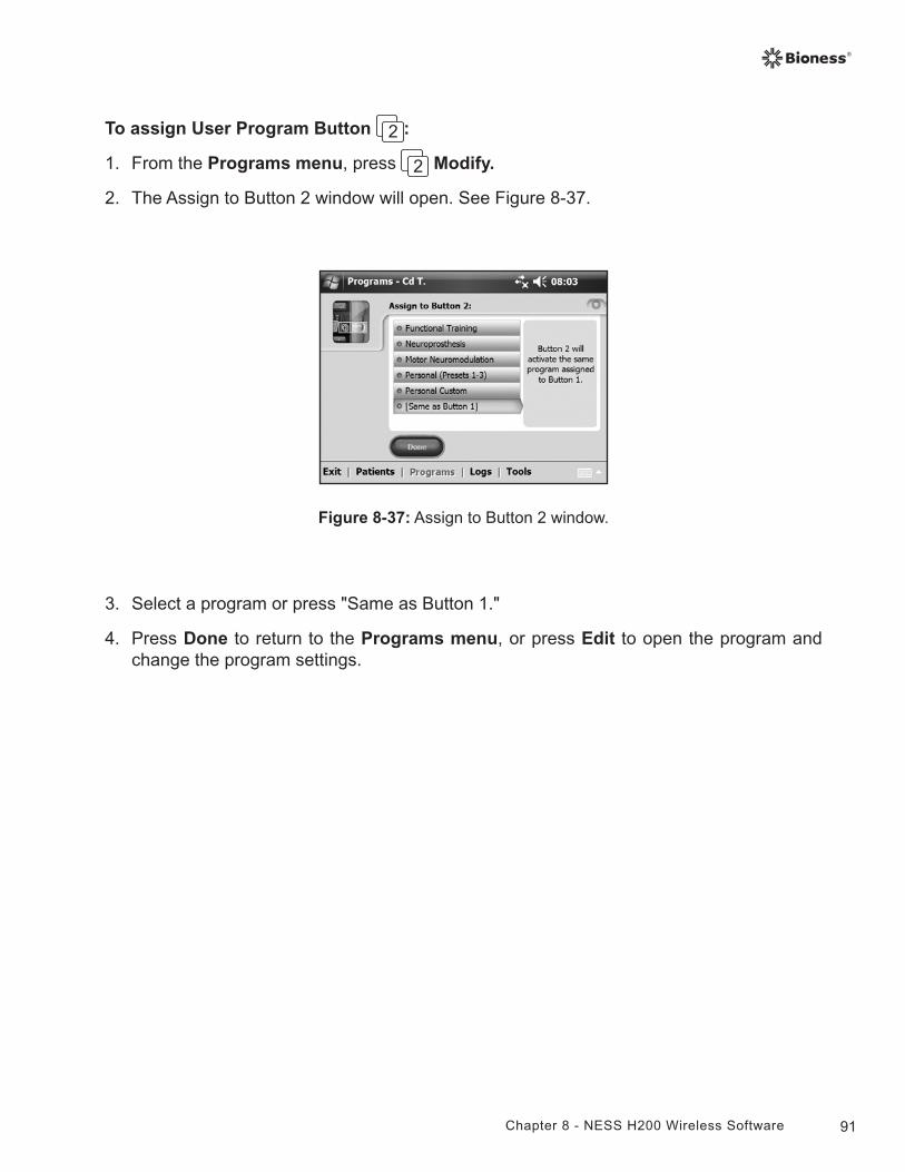
91Chapter 8 - NESS H200 Wireless Software
To assign User Program Button :
1. From the Programs menu, press Modify.
2. The Assign to Button 2 window will open. See Figure 8-37.
3. Select a program or press "Same as Button 1."
4. Press Done to return to the Programs menu, or press Edit to open the program and change the program settings.
Figure 8-37: Assign to Button 2 window.
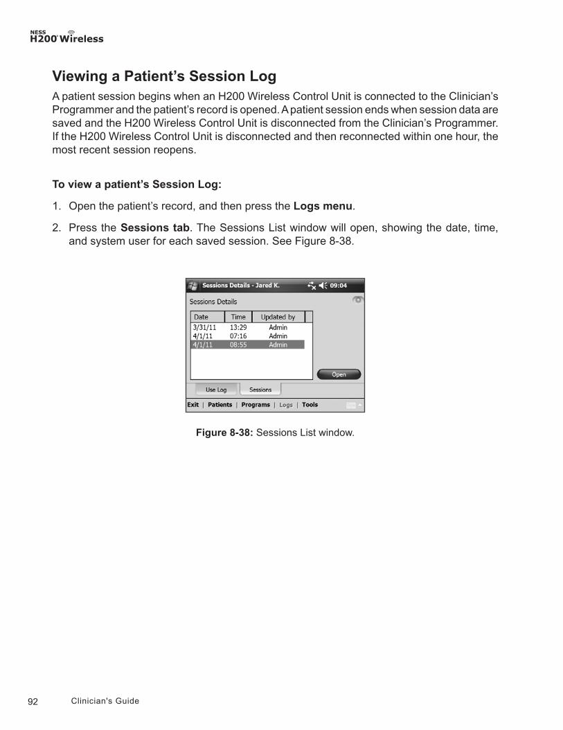
92 Clinician's Guide
Viewing a Patient’s Session LogA patient session begins when an H200 Wireless Control Unit is connected to the Clinician’s Programmer and the patient’s record is opened. A patient session ends when session data are saved and the H200 Wireless Control Unit is disconnected from the Clinician’s Programmer. If the H200 Wireless Control Unit is disconnected and then reconnected within one hour, the most recent session reopens.
To view a patient’s Session Log:
1. Open the patient’s record, and then press the Logs menu.
2. Press the Sessions tab. The Sessions List window will open, showing the date, time, and system user for each saved session. See Figure 8-38.
Figure 8-38: Sessions List window.
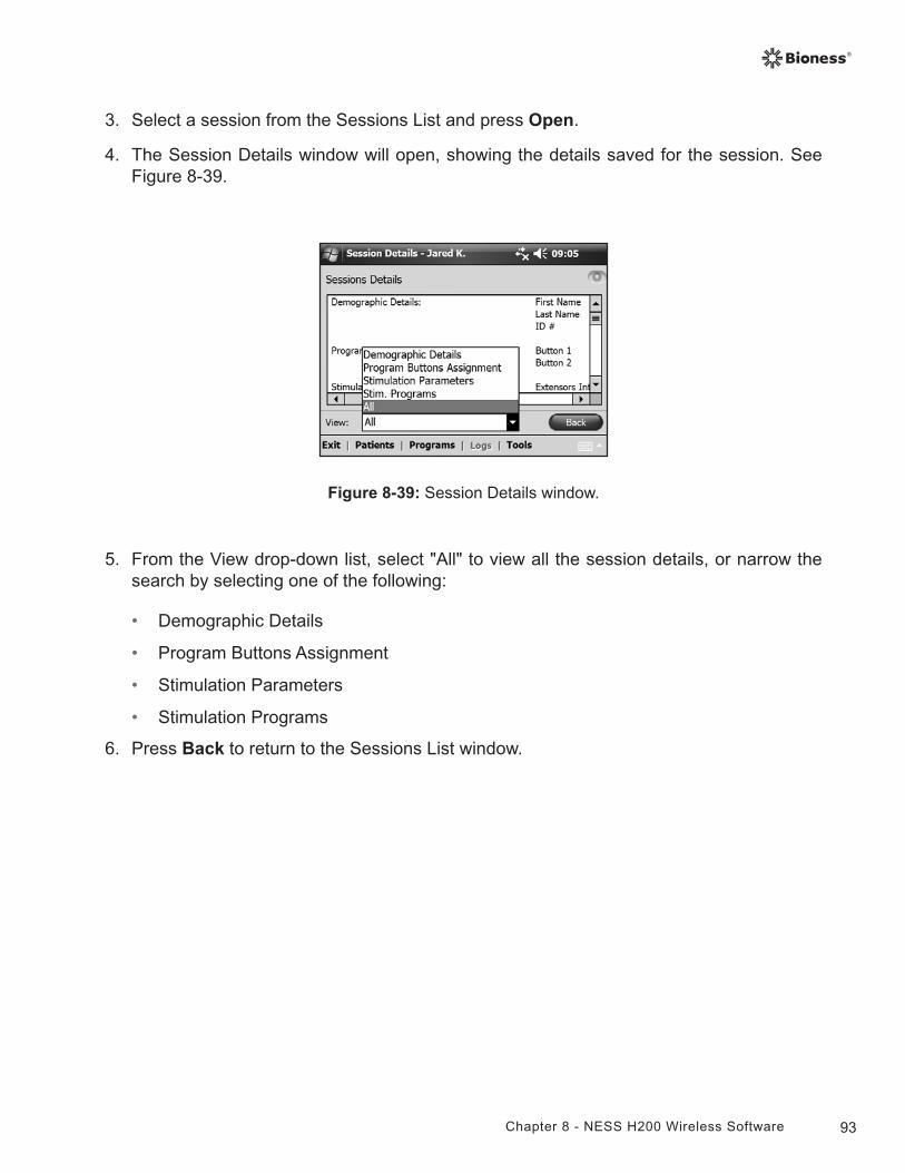
93Chapter 8 - NESS H200 Wireless Software
Figure 8-39: Session Details window.
3. Select a session from the Sessions List and press Open.
4. The Session Details window will open, showing the details saved for the session. See Figure 8-39.
5. From the View drop-down list, select "All" to view all the session details, or narrow the search by selecting one of the following:
• Demographic Details
• Program Buttons Assignment
• Stimulation Parameters
• Stimulation Programs
6. Press Back to return to the Sessions List window.
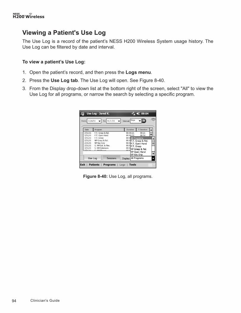
94 Clinician's Guide
Viewing a Patient's Use LogThe Use Log is a record of the patient’s NESS H200 Wireless System usage history. The Use Log can be filtered by date and interval.
To view a patient’s Use Log:
1. Open the patient’s record, and then press the Logs menu.
2. Press the Use Log tab. The Use Log will open. See Figure 8-40.
3. From the Display drop-down list at the bottom right of the screen, select "All" to view the Use Log for all programs, or narrow the search by selecting a specific program.
Figure 8-40: Use Log, all programs.
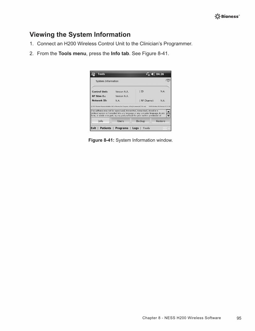
95Chapter 8 - NESS H200 Wireless Software
Viewing the System Information1. Connect an H200 Wireless Control Unit to the Clinician’s Programmer.
2. From the Tools menu, press the Info tab. See Figure 8-41.
Figure 8-41: System Information window.
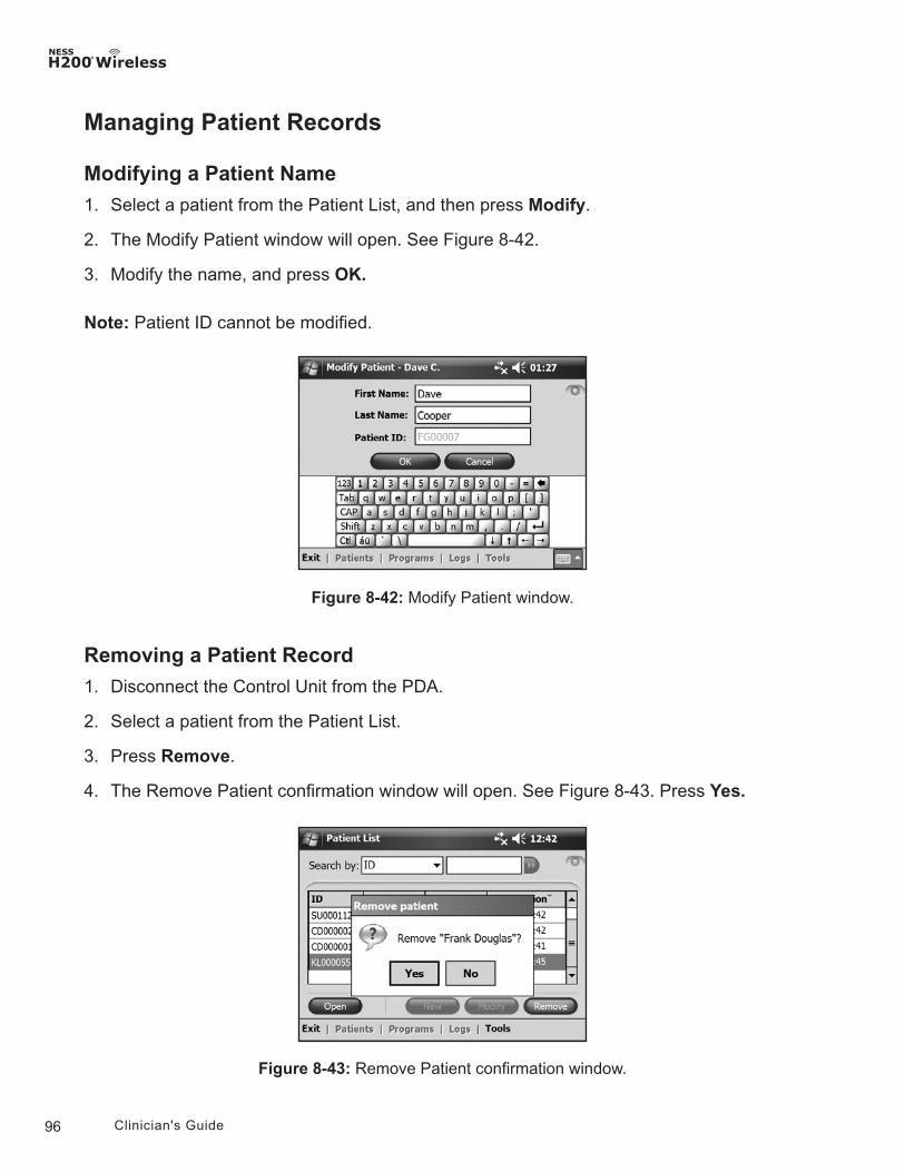
96 Clinician's Guide
Figure 8-42: Modify Patient window.
Managing Patient Records
Modifying a Patient Name
1. Select a patient from the Patient List, and then press Modify.
2. The Modify Patient window will open. See Figure 8-42.
3. Modify the name, and press OK.
Note: Patient ID cannot be modified.
Removing a Patient Record
1. Disconnect the Control Unit from the PDA.
2. Select a patient from the Patient List.
3. Press Remove.
4. The Remove Patient confirmation window will open. See Figure 8-43. Press Yes.
Figure 8-43: Remove Patient confirmation window.
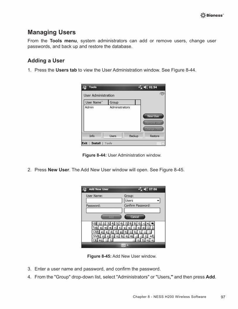
97Chapter 8 - NESS H200 Wireless Software
Managing UsersFrom the Tools menu, system administrators can add or remove users, change user passwords, and back up and restore the database.
Adding a User
1. Press the Users tab to view the User Administration window. See Figure 8-44.
Figure 8-44: User Administration window.
2. Press New User. The Add New User window will open. See Figure 8-45.
Figure 8-45: Add New User window.
3. Enter a user name and password, and confirm the password.
4. From the "Group" drop-down list, select "Administrators" or "Users," and then press Add.
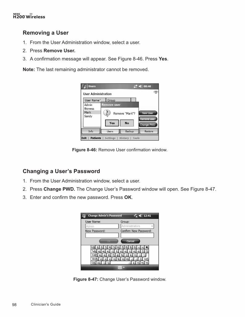
98 Clinician's Guide
Figure 8-46: Remove User confirmation window.
Removing a User
1. From the User Administration window, select a user.
2. Press Remove User.
3. A confirmation message will appear. See Figure 8-46. Press Yes.
Note: The last remaining administrator cannot be removed.
Changing a User’s Password
1. From the User Administration window, select a user.
2. Press Change PWD. The Change User’s Password window will open. See Figure 8-47.
3. Enter and confirm the new password. Press OK.
Figure 8-47: Change User’s Password window.
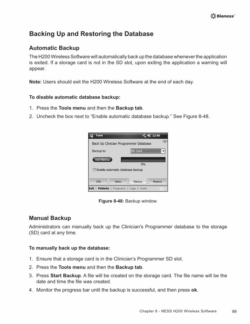
99Chapter 8 - NESS H200 Wireless Software
Backing Up and Restoring the Database
Automatic Backup
The H200 Wireless Software will automatically back up the database whenever the application is exited. If a storage card is not in the SD slot, upon exiting the application a warning will appear.
Note: Users should exit the H200 Wireless Software at the end of each day.
To disable automatic database backup:
1. Press the Tools menu and then the Backup tab.
2. Uncheck the box next to “Enable automatic database backup.” See Figure 8-48.
Figure 8-48: Backup window.
Manual Backup
Administrators can manually back up the Clinician's Programmer database to the storage (SD) card at any time.
To manually back up the database:
1. Ensure that a storage card is in the Clinician’s Programmer SD slot.
2. Press the Tools menu and then the Backup tab.
3. Press Start Backup. A file will be created on the storage card. The file name will be the date and time the file was created.
4. Monitor the progress bar until the backup is successful, and then press ok.
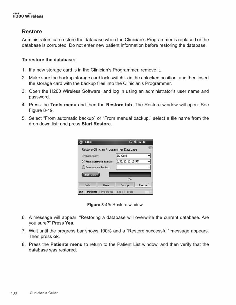
100 Clinician's Guide
Restore
Administrators can restore the database when the Clinician’s Programmer is replaced or the database is corrupted. Do not enter new patient information before restoring the database.
To restore the database:
1. If a new storage card is in the Clinician’s Programmer, remove it.
2. Make sure the backup storage card lock switch is in the unlocked position, and then insert the storage card with the backup files into the Clinician’s Programmer.
3. Open the H200 Wireless Software, and log in using an administrator’s user name and password.
4. Press the Tools menu and then the Restore tab. The Restore window will open. See Figure 8-49.
5. Select “From automatic backup” or “From manual backup,” select a file name from the drop down list, and press Start Restore.
Figure 8-49: Restore window.
6. A message will appear: “Restoring a database will overwrite the current database. Are you sure?” Press Yes.
7. Wait until the progress bar shows 100% and a “Restore successful” message appears. Then press ok.
8. Press the Patients menu to return to the Patient List window, and then verify that the database was restored.
101Chapter 9 - Patient Training and Follow-Up
9Chapter
Patient Training and Follow-Up
Patient TrainingClinicians should train patients on the setup, operation, and maintenance of their NESS H200 Wireless System. Patients should be able to follow their H200 Wireless training program, identify problems, and know whom to contact for assistance.
Patient training should include the following topics:
• Review of the H200 Wireless User Reference Card and User’s Guide.
• How to don and doff the Orthosis.
• How to operate the NESS H200 Wireless System.
• System maintenance and cleaning Instructions.
• Basic troubleshooting.
• Review of the patient's personal training program.
• Practice with the NESS H200 Wireless System.
Many of the above topics are covered in the H200 Wireless User’s Guide. This section discusses some additional points to consider.
102 Clinician's Guide
Donning/Doffing the H200 Wireless Orthosis
Remind patients to:
• Remove any lotions or oils from their hand and forearm with soap and water.
• Make sure the cloth electrodes are wet and have no dry patches. Dry patches reduce the stimulation current reaching the arm/hand.
• Manually extend their fingers, wrist, elbow, and shoulder, if necessary, to make it easier to don the Orthosis.
• Put the spiral end of the Orthosis on first.
• Check the position of the wrist bridge and thenar before bringing the flexor support under the forearm. The wrist bridge should lie across the wrist and the thenar should sit on the thenar eminence. Make sure patients can identify the correct position of the Orthosis on the arm/hand. Poor positioning may result in poor or unbalanced activation of the hand, and pressure marks on the skin around the wrist.
• Remove and reposition the Orthosis if it is positioned too distally on the hand. Remind patients not to slide the Orthosis on the forearm.
• Close the wing arm firmly, and check for gaps between the arm and the Orthosis. There should be no visible gaps.
• Check the position of the Orthosis using the stimulation test button on the Control Unit. Press once to check the extensors. Press again to check the flexors.
103Chapter 9 - Patient Training and Follow-Up
Operating the NESS H200 Wireless System
Review with patients how to:
• Turn on the system.
• Test stimulation in the Orthosis using the stimulation test button.
• Select User Program 1 and 2.
• Turn on/off and pause stimulation using the Control Unit and Orthosis trigger button.
• Increase/decrease stimulation intensity.
• Mute/un-mute the audio alerts for the Orthosis and Control Unit.
• Electronically register a replacement Control Unit or Orthosis.
Maintaining and Cleaning the NESS H200 Wireless System
Review with patients how to:
• Charge the Orthosis and Control Unit batteries.
• Wet the cloth electrodes and when to replace them.
• Clean and disinfect the NESS H200 Wireless System components and NESS H200 Wireless System Kit carrying case.
• Clean the electrode bases.
Troubleshooting
Instruct patients to contact you or the Bioness Client Relations Department if they have any questions or problems. Bioness Client Relations Department: (800) 211-9136, Option 3.
Practicing with the NESS H200 Wireless System
Have patients set up and operate the NESS H200 Wireless System, following their training program.
104 Clinician's Guide
Patient Follow-Up and Clinical Support
A patient follow-up and clinical support program should:
• Evaluate the benefits of continuing with the chosen selected programs.
• Monitor clinical progress.
• Maximize clinical effectiveness.
• Provide clinical and technical support.
Suggested Follow-up Agenda
1. Check the Orthosis and Control Unit.
2. Check the patient's Use Log.
3. Perform a clinical evaluation.
4. If necessary, adjust the stimulation parameters.
5. If necessary, update the patient's training program.
6. If appropriate, train the patient on additional exercises (for example, passive range of motion exercises and functional training).
7. If appropriate, assign different programs to the Control Unit Program 1 and Program 2 buttons.
8. Set a date for the next follow-up visit.
105Chapter 10 - Maintenance and Cleaning
10Chapter
Maintenance and Cleaning
ChargingThe H200 Wireless Clinician's Programmer should be charged at least four hours before use, daily, and when a low battery indicator is displayed.
Batteries
HP iPAQ Clinician’s Programmer
During extended periods of nonuse, remove the battery from the HP iPAQ Clinician’s Programmer. Refer to the PDA manufacturer’s instructions for information on battery removal and replacement.
H200 Wireless Orthosis
The Orthosis rechargeable batteries may need to be replaced approximately every two years. The batteries should only be replaced by a Bioness Inc certified technician. Contact the Bioness Client Relations Department at (800) 211-9136, Option 3, for assistance.
H200 Wireless Control Unit
Refer to the H200 Wireless User’s Guide for battery replacement instructions.
WARNING: Do not simultaneously charge the H200 Wireless Control Unit, Orthosis, and Clinician’s Programmer while the Control Unit is connected to the Configuration Cradle.
WARNING: The H200 Wireless Orthosis can be worn while the Orthosis and Control Unit are charging, as long as the Control Unit is NOT connected to the Clinician's Programmer while the Clinician's Programmer is charging.
CAUTION: Use only a battery provided by Bioness Inc.
106 Clinician's Guide
H200 Wireless Cloth ElectrodesThe H200 Wireless Cloth Electrodes should be replaced every two weeks, or sooner if they become damaged.
The H200 Wireless Cloth Electrodes should be wet before use and after three to four hours of use. Remove the cloth electrodes from the Orthosis before wetting them.
Electrode BasesTo replace the electrode bases, unscrew and remove them from the Orthosis. Then follow the fitting procedure for attaching the electrode bases.
Electronic RegistrationA replacement H200 Wireless Control Unit will need to be electronically registered to the existing H200 Wireless Orthosis for the components to communicate wirelessly. See the H200 Wireless User’s Guide for instructions on electronically registering a replacement H200 Wireless Control Unit.
A replacement H200 Wireless Orthosis will need to be electronically registered to the existing H200 Wireless Control Unit for the components to communicate wirelessly. See the H200 Wireless User’s Guide for instructions on electronically registering a replacement Orthosis.
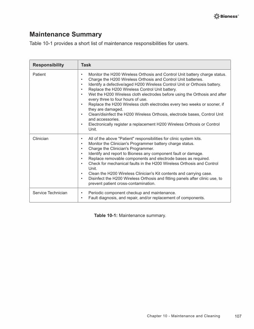
107Chapter 10 - Maintenance and Cleaning
Table 10-1: Maintenance summary.
Responsibility Task
Patient • Monitor the H200 Wireless Orthosis and Control Unit battery charge status.• Charge the H200 Wireless Orthosis and Control Unit batteries.• Identify a defective/aged H200 Wireless Control Unit or Orthosis battery.• Replace the H200 Wireless Control Unit battery.• Wet the H200 Wireless cloth electrodes before using the Orthosis and after
every three to four hours of use.• Replace the H200 Wireless cloth electrodes every two weeks or sooner, if
they are damaged.• Clean/disinfect the H200 Wireless Orthosis, electrode bases, Control Unit
and accessories.• Electronically register a replacement H200 Wireless Orthosis or Control
Unit.
Clinician • All of the above "Patient" responsibilities for clinic system kits.• Monitor the Clinician's Programmer battery charge status.• Charge the Clinician's Programmer.• Identify and report to Bioness any component fault or damage.• Replace removable components and electrode bases as required.• Check for mechanical faults in the H200 Wireless Orthosis and Control
Unit.• Clean the H200 Wireless Clinician's Kit contents and carrying case.• Disinfect the H200 Wireless Orthosis and fitting panels after clinic use, to
prevent patient cross-contamination.
Service Technician • Periodic component checkup and maintenance.• Fault diagnosis, and repair, and/or replacement of components.
Maintenance SummaryTable 10-1 provides a short list of maintenance responsibilities for users.
108 Clinician's Guide
Cleaning the H200 Wireless ComponentsAll H200 Wireless components may be cleaned as needed or weekly by carefully wiping them with a damp cloth. The electrical components are not waterproof. Do not immerse them in water.
Disinfecting the H200 Wireless Components
Electronic Components
The H200 Wireless Control Unit may be cleaned and low-level disinfected using CaviWipes™ (Metrex, Orange, CA), or wipes or cloths saturated (but not dripping) with 70% isopropyl alcohol (IPA) per the instructions below:
1. Use one saturated disinfectant wipe or cloth to thoroughly wet the component surface.
2. Use a second saturated disinfectant wipe or cloth to remove any surface contaminants. Soil, etc., will impede the disinfectant's effectiveness, if not removed.
3. As needed, use additional saturated disinfectant wipes or cloths to keep the component surface wet for 3 minutes.
Note: Be sure to follow the Bioness instructions for the specified contact time to ensure an effective bacteria kill.
The H200 Wireless Orthosis (except for the wrist insert) may be cleaned and low-level disinfected using wipes or cloths saturated with 70% isopropyl alcohol (IPA) per the instructions below:
1. Use one saturated disinfectant wipe or cloth to thoroughly wet the component surface.
2. Use a second saturated disinfectant wipe or cloth to remove any surface contaminants. Soil, etc., will impede the disinfectant's effectiveness, if not removed.
3. As needed, use additional saturated disinfectant wipes or cloths to keep the components surface wet for 3 minutes.
Note: Be sure to follow the Bioness instructions for the specified contact time to ensure an effective bacteria kill.
WARNING: Disinfect the fitting panels and Orthosis between uses to prevent patient cross contamination.
109Chapter 10 - Maintenance and Cleaning
Wrist Insert
The wrist insert cannot be disinfected. The wrist insert can only be cleaned with soap and water. Do not use 70% IPA on the wrist insert. Use the single-use wrist insert covers to prevent patient cross-contamination.
Clinician Kit Carrying CaseThe H200 Wireless Clinician Kit carrying case may be cleaned and low-level disinfected using CaviCide® (Metrex, Orange, CA) or 70% isopropyl alcohol (IPA) per the following instructions:
CaviCide:
1. Spray the entire surface of the Clinician Kit carrying case with CaviCide.
2. Use a clean towel to remove any surface contaminants. Soil, etc., will impede the disinfectant's effectiveness, if not removed.
3. Spray the entire surface of the Clinician Kit carrying case again with CaviCide.
4. Keep spraying the entire carrying case surface as needed to keep it wet for 10 minutes.
70% IPA:
1. Wipe the entire surface of the Clinician Kit carrying case with a cloth or wipe saturated with 70% IPA.
2. Use a new cloth or wipe saturated with 70% IPA to remove any surface contaminants. Soil, etc., will impede the disinfectant's effectiveness, if not removed.
3. Wipe the entire surface of the Clinician Kit carrying case again with a new cloth or wipe saturated with 70% IPA.
4. Use additional new cloths or wipes saturated with 70% IPA as needed to keep the entire surface of the carrying case wet for 10 minutes.
Note: Be sure to follow the Bioness instructions for the specified contact time to ensure an effective bacteria kill.
Note: Do not use other cleaning/disinfecting agents such as a diluted bleach mixture, Lysol or Clorox wipes. Bioness has not tested these products' effectiveness on the H200 Wireless components.
Metrex products are sold through authorized dealers worldwide; 70% IPA is available at your local drugstore or pharmacy. If you need assistance, please call theBioness Client Relations Department at (800) 211-9136, Option 3.

110 Clinician's Guide
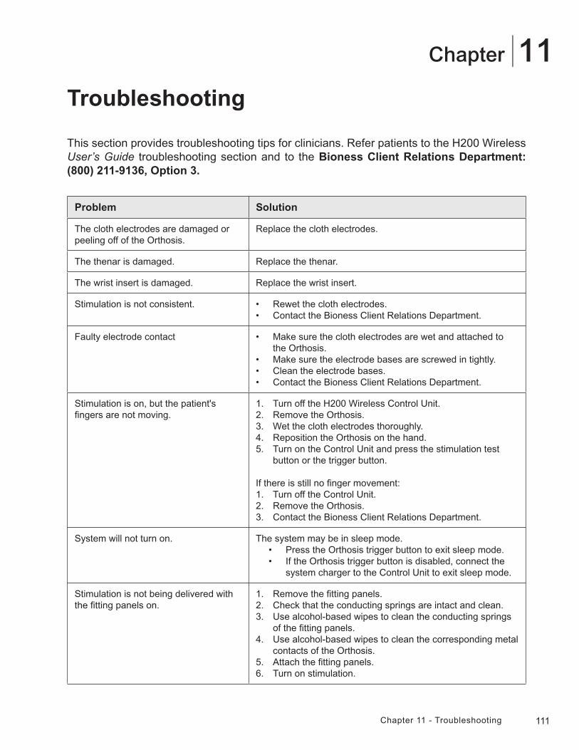
111Chapter 11 - Troubleshooting
11Chapter
Troubleshooting
This section provides troubleshooting tips for clinicians. Refer patients to the H200 Wireless User’s Guide troubleshooting section and to the Bioness Client Relations Department: (800) 211-9136, Option 3.
Problem Solution
The cloth electrodes are damaged or peeling off of the Orthosis.
Replace the cloth electrodes.
The thenar is damaged. Replace the thenar.
The wrist insert is damaged. Replace the wrist insert.
Stimulation is not consistent. • Rewet the cloth electrodes.• Contact the Bioness Client Relations Department.
Faulty electrode contact • Make sure the cloth electrodes are wet and attached to the Orthosis.
• Make sure the electrode bases are screwed in tightly.• Clean the electrode bases.• Contact the Bioness Client Relations Department.
Stimulation is on, but the patient's fingers are not moving.
1. Turn off the H200 Wireless Control Unit. 2. Remove the Orthosis.3. Wet the cloth electrodes thoroughly.4. Reposition the Orthosis on the hand.5. Turn on the Control Unit and press the stimulation test
button or the trigger button.
If there is still no finger movement:1. Turn off the Control Unit.2. Remove the Orthosis.3. Contact the Bioness Client Relations Department.
System will not turn on. The system may be in sleep mode.• Press the Orthosis trigger button to exit sleep mode.• If the Orthosis trigger button is disabled, connect the
system charger to the Control Unit to exit sleep mode.
Stimulation is not being delivered with the fitting panels on.
1. Remove the fitting panels.2. Check that the conducting springs are intact and clean.3. Use alcohol-based wipes to clean the conducting springs
of the fitting panels.4. Use alcohol-based wipes to clean the corresponding metal
contacts of the Orthosis.5. Attach the fitting panels.6. Turn on stimulation.
112 Clinician's Guide
Frequently Asked QuestionsIf you have any questions or concerns, please contact the Bioness Client Relations Department at (800) 211-9136, Option 3.
Our clinic owns multiple NESS H200 Wireless Systems. How can we identify which electronic components belong to which H200 Wireless system?
• Each NESS H200 Wireless System has an alphanumeric System Identification (ID) Number (for example, A123) printed on the back of the H200 Wireless Control Unit and under the wing of the H200 Wireless Orthosis. The System ID Numbers on the two electronic components must match for the system to work. Check the numbers before use to see if they match.
The H200 Wireless Software buttons used to create a new patient record or adjust the settings for a current patient are grayed out and nonfunctional.
• The Clinician’s Programmer and the H200 Wireless Control Unit are not communicating. Both must be connected to the Configuration Cradle communication connector cable to communicate. Turn off the H200 Wireless Control Unit or place it in standby mode. Then reconnect the Configuration Cradle communication connector cable to the H200 Wireless Control Unit and the Clinician’s Programmer.
I connected the H200 Wireless Control Unit to the Configuration Cradle and a message appeared on the Clinician’s Programmer. The message says that the date and time in the H200 Wireless Control Unit differ from those in the Clinician’s Programmer.
• The clocks on the H200 Wireless Control Unit and Clinician’s Programmer must be synchronized for the Use Log and Session Log to record accurately.
• If the date and time settings of the Clinician’s Programmer are correct, update the H200 Wireless Control Unit clock.
• If the date and time settings of the Clinician’s Programmer are not correct, press Exit to close the H200 Wireless Software and open the PDA settings screen. (See the PDA manufacturer’s instructions.) Use the stylus to adjust the Clinician’s Programmer time zone, clock, and date. Press Ok to save the settings. Log back into the H200 Wireless Software, reconnect the H200 Wireless Control Unit, and update the NESS H200 Wireless System clock to match the Clinician’s Programmer clock.
113Chapter 11 -Troubleshooting
I connected the H200 Wireless Control Unit to the Configuration Cradle, and a message appeared on the Clinician’s Programmer. The message says that a new patient was found and asks if I would like to add this record to the database.
• Select Yes, if you want to review or make changes to the patient’s settings. If not, select No to return to the Patient List. If you want to copy a different patient record onto the H200 Wireless Control Unit, then, with the H200 Wireless Control Unit still connected to the Configuration Cradle, open another patient record or create a new patient record for use with the H200 Wireless Control Unit. Note: If you open another patient record while the H200 Wireless Control Unit is connected, the data on the NESS H200 Wireless System will be permanently overwritten by the record that is opened.
When I connected the H200 Wireless Control Unit to the Configuration Cradle, a message appeared on the Clinician’s Programmer saying that the parameters are inconsistent.
• A different Clinician’s Programmer was last used to update the connected NESS H200 Wireless System.
• Press System to overwrite the data on the Clinician’s Programmer with the data on the H200 Wireless Control System (preferred when patients have been using the NESS H200 Wireless System settings and are returning for a follow-up evaluation).
• Press Database to overwrite the parameters on the NESS H200 Wireless System with the parameters on the Clinician’s Programmer database.
• Press Ignore to leave the parameters on the Clinician’s Programmer and the NESS H200 Wireless System unchanged.
When charging the NESS H200 Wireless System, how will I know when the batteries are fully charged?
• When the H200 Wireless Control Unit is fully charged, a horizontal GREEN line will appear in the H200 Wireless Control Unit digital display.
• When the H200 Wireless Orthosis is fully charged, the status light for the RF Stim Unit will be SOLID GREEN.
• Charging takes approximately three hours. After the components are fully charged, keep the components connected to the system charger until ready to use.
WARNING: Do not simultaneously charge the H200 Wireless Control Unit, Orthosis, and Clinician’s Programmer while the Control Unit is connected to the Configuration Cradle.
114 Clinician's Guide
After I fully charged the H200 Wireless Control Unit and Orthosis, I disconnected the system charger and then immediately reconnected it. The charging icons displayed again on the H200 Wireless Control Unit and Orthosis. Do I need to repeat the charging process?
• If you recently charged your system and the fully charged icons were displayed, your system is still fully charged. You do not have to repeat the charging process.
I received a replacement Control Unit/Orthosis and was told I need to register it. Why is registration important, and how do I register a component?
• A replacement H200 Wireless Control Unit or Orthosis needs to be electronically registered to the existing H200 Wireless component to communicate wirelessly. To electronically register a replacement component, see the H200 Wireless User’s Guide.
I tried the registration procedure, but I never saw the ALTERNATING GREEN arches in the digital display. The replacement component is not working.
• Clinical mode may have been started instead of the registration process. Clinical mode is started by pressing the minus and on/off buttons on the H200 Wireless Control Unit. Registration is started with the H200 Wireless Control Unit off, and then by pressing the minus and trigger buttons on the H200 Wireless Control Unit. Turn off the H200 Wireless Control Unit, and press the minus and trigger buttons to restart the registration process.
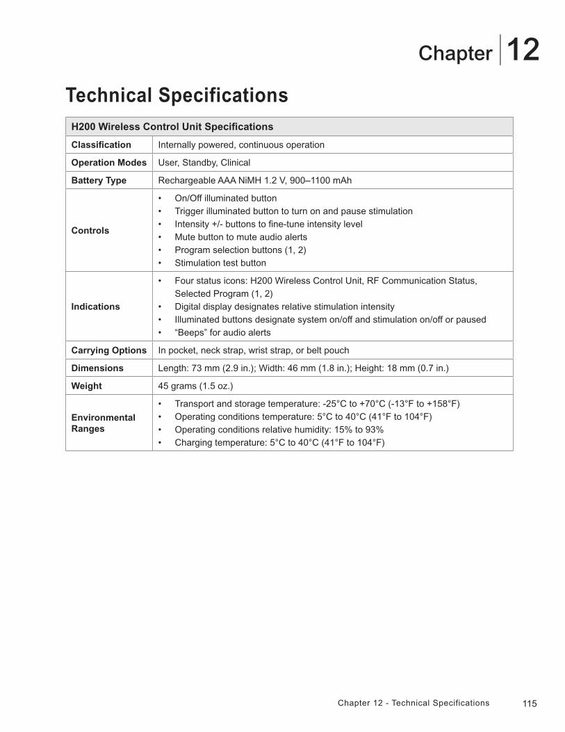
115Chapter 12 - Technical Specifications
12Chapter
Technical SpecificationsH200 Wireless Control Unit Specifications
Classification Internally powered, continuous operation
Operation Modes User, Standby, Clinical
Battery Type Rechargeable AAA NiMH 1.2 V, 900–1100 mAh
Controls
• On/Off illuminated button• Trigger illuminated button to turn on and pause stimulation• Intensity +/- buttons to fine-tune intensity level• Mute button to mute audio alerts• Program selection buttons (1, 2)• Stimulation test button
Indications
• Four status icons: H200 Wireless Control Unit, RF Communication Status, Selected Program (1, 2)
• Digital display designates relative stimulation intensity• Illuminated buttons designate system on/off and stimulation on/off or paused• “Beeps” for audio alerts
Carrying Options In pocket, neck strap, wrist strap, or belt pouch
Dimensions Length: 73 mm (2.9 in.); Width: 46 mm (1.8 in.); Height: 18 mm (0.7 in.)
Weight 45 grams (1.5 oz.)
Environmental Ranges
• Transport and storage temperature: -25°C to +70°C (-13°F to +158°F)• Operating conditions temperature: 5°C to 40°C (41°F to 104°F) • Operating conditions relative humidity: 15% to 93%• Charging temperature: 5°C to 40°C (41°F to 104°F)
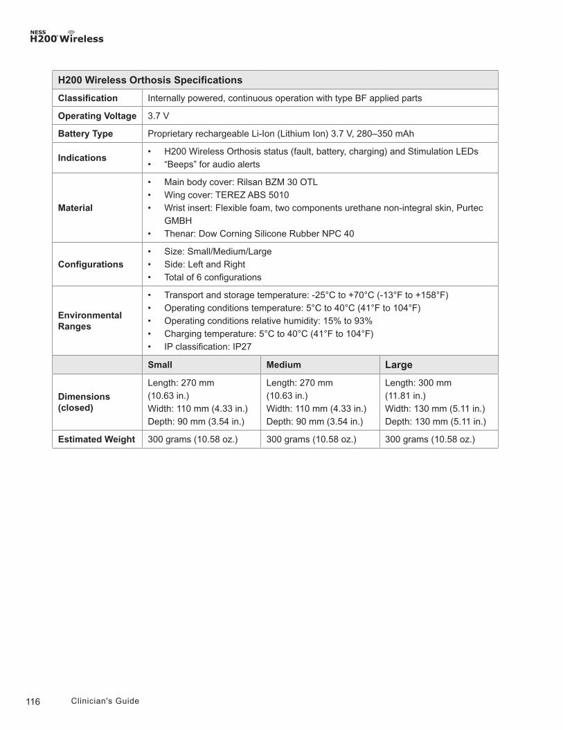
116 Clinician's Guide
H200 Wireless Orthosis Specifications
Classification Internally powered, continuous operation with type BF applied parts
Operating Voltage 3.7 V
Battery Type Proprietary rechargeable Li-Ion (Lithium Ion) 3.7 V, 280–350 mAh
Indications• H200 Wireless Orthosis status (fault, battery, charging) and Stimulation LEDs• “Beeps” for audio alerts
Material
• Main body cover: Rilsan BZM 30 OTL• Wing cover: TEREZ ABS 5010• Wrist insert: Flexible foam, two components urethane non-integral skin, Purtec
GMBH• Thenar: Dow Corning Silicone Rubber NPC 40
Configurations• Size: Small/Medium/Large• Side: Left and Right• Total of 6 configurations
Environmental Ranges
• Transport and storage temperature: -25°C to +70°C (-13°F to +158°F)• Operating conditions temperature: 5°C to 40°C (41°F to 104°F) • Operating conditions relative humidity: 15% to 93%• Charging temperature: 5°C to 40°C (41°F to 104°F) • IP classification: IP27
Small Medium Large
Dimensions (closed)
Length: 270 mm(10.63 in.)Width: 110 mm (4.33 in.)Depth: 90 mm (3.54 in.)
Length: 270 mm(10.63 in.)Width: 110 mm (4.33 in.)Depth: 90 mm (3.54 in.)
Length: 300 mm(11.81 in.)Width: 130 mm (5.11 in.)Depth: 130 mm (5.11 in.)
Estimated Weight 300 grams (10.58 oz.) 300 grams (10.58 oz.) 300 grams (10.58 oz.)
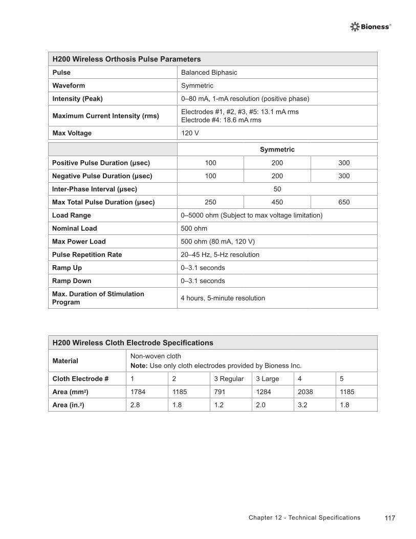
117Chapter 12 - Technical Specifications
H200 Wireless Orthosis Pulse Parameters
Pulse Balanced Biphasic
Waveform Symmetric
Intensity (Peak) 0–80 mA, 1-mA resolution (positive phase)
Maximum Current Intensity (rms)Electrodes #1, #2, #3, #5: 13.1 mA rmsElectrode #4: 18.6 mA rms
Max Voltage 120 V
Symmetric
Positive Pulse Duration (µsec) 100 200 300
Negative Pulse Duration (µsec) 100 200 300
Inter-Phase Interval (µsec) 50
Max Total Pulse Duration (µsec) 250 450 650
Load Range 0–5000 ohm (Subject to max voltage limitation)
Nominal Load 500 ohm
Max Power Load 500 ohm (80 mA, 120 V)
Pulse Repetition Rate 20–45 Hz, 5-Hz resolution
Ramp Up 0–3.1 seconds
Ramp Down 0–3.1 seconds
Max. Duration of Stimulation Program
4 hours, 5-minute resolution
H200 Wireless Cloth Electrode Specifications
MaterialNon-woven clothNote: Use only cloth electrodes provided by Bioness Inc.
Cloth Electrode # 1 2 3 Regular 3 Large 4 5
Area (mm2) 1784 1185 791 1284 2038 1185
Area (in.2) 2.8 1.8 1.2 2.0 3.2 1.8
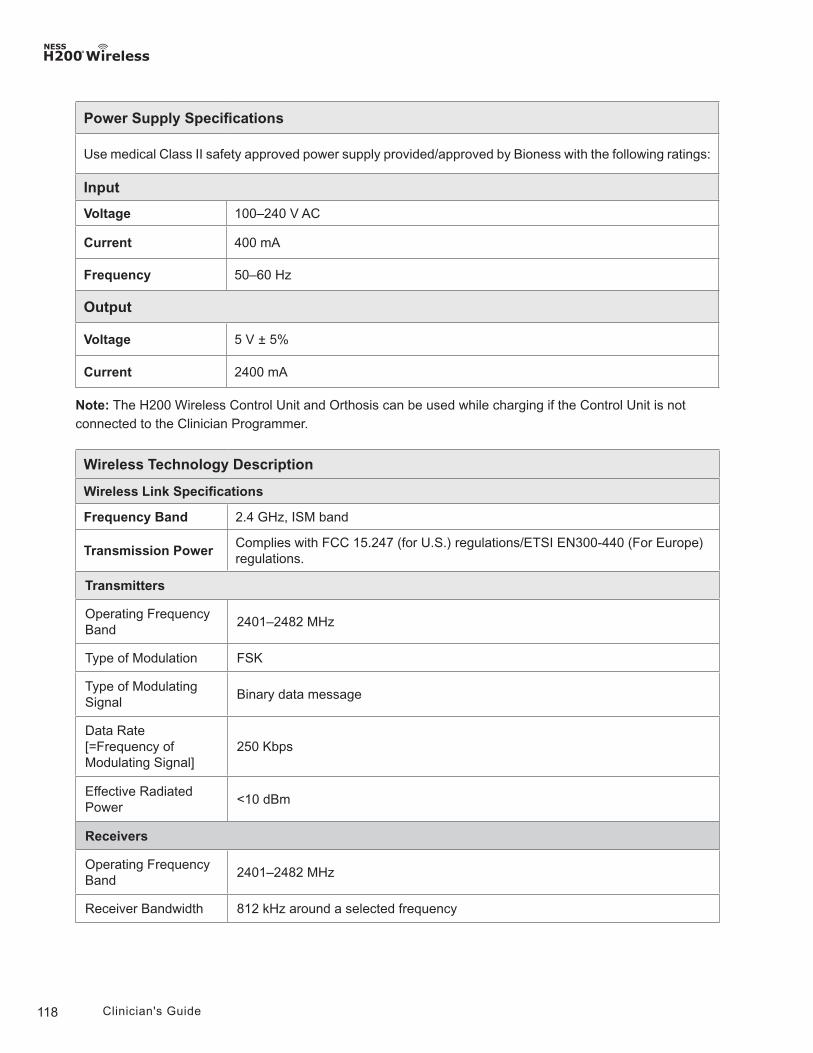
118 Clinician's Guide
Power Supply Specifications
Use medical Class II safety approved power supply provided/approved by Bioness with the following ratings:
Input
Voltage 100–240 V AC
Current 400 mA
Frequency 50–60 Hz
Output
Voltage 5 V ± 5%
Current 2400 mA
Note: The H200 Wireless Control Unit and Orthosis can be used while charging if the Control Unit is not connected to the Clinician Programmer.
Wireless Technology Description
Wireless Link Specifications
Frequency Band 2.4 GHz, ISM band
Transmission PowerComplies with FCC 15.247 (for U.S.) regulations/ETSI EN300-440 (For Europe) regulations.
Transmitters
Operating Frequency Band
2401–2482 MHz
Type of Modulation FSK
Type of Modulating Signal
Binary data message
Data Rate [=Frequency of Modulating Signal]
250 Kbps
Effective Radiated Power
<10 dBm
Receivers
Operating Frequency Band
2401–2482 MHz
Receiver Bandwidth 812 kHz around a selected frequency
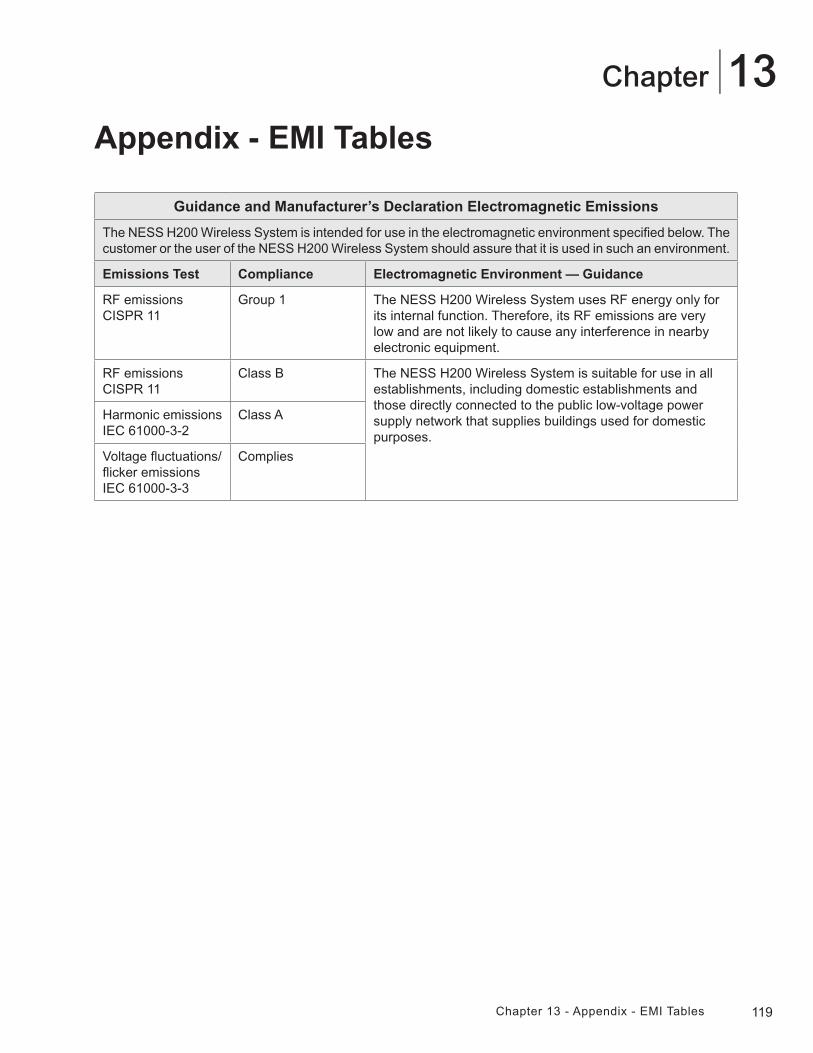
119Chapter 13 - Appendix - EMI Tables
13Chapter
Guidance and Manufacturer’s Declaration Electromagnetic Emissions
The NESS H200 Wireless System is intended for use in the electromagnetic environment specified below. The customer or the user of the NESS H200 Wireless System should assure that it is used in such an environment.
Emissions Test Compliance Electromagnetic Environment — Guidance
RF emissionsCISPR 11
Group 1 The NESS H200 Wireless System uses RF energy only for its internal function. Therefore, its RF emissions are very low and are not likely to cause any interference in nearby electronic equipment.
RF emissionsCISPR 11
Class B The NESS H200 Wireless System is suitable for use in all establishments, including domestic establishments and those directly connected to the public low-voltage power supply network that supplies buildings used for domestic purposes.
Harmonic emissionsIEC 61000-3-2
Class A
Voltage fluctuations/flicker emissionsIEC 61000-3-3
Complies
Appendix - EMI Tables
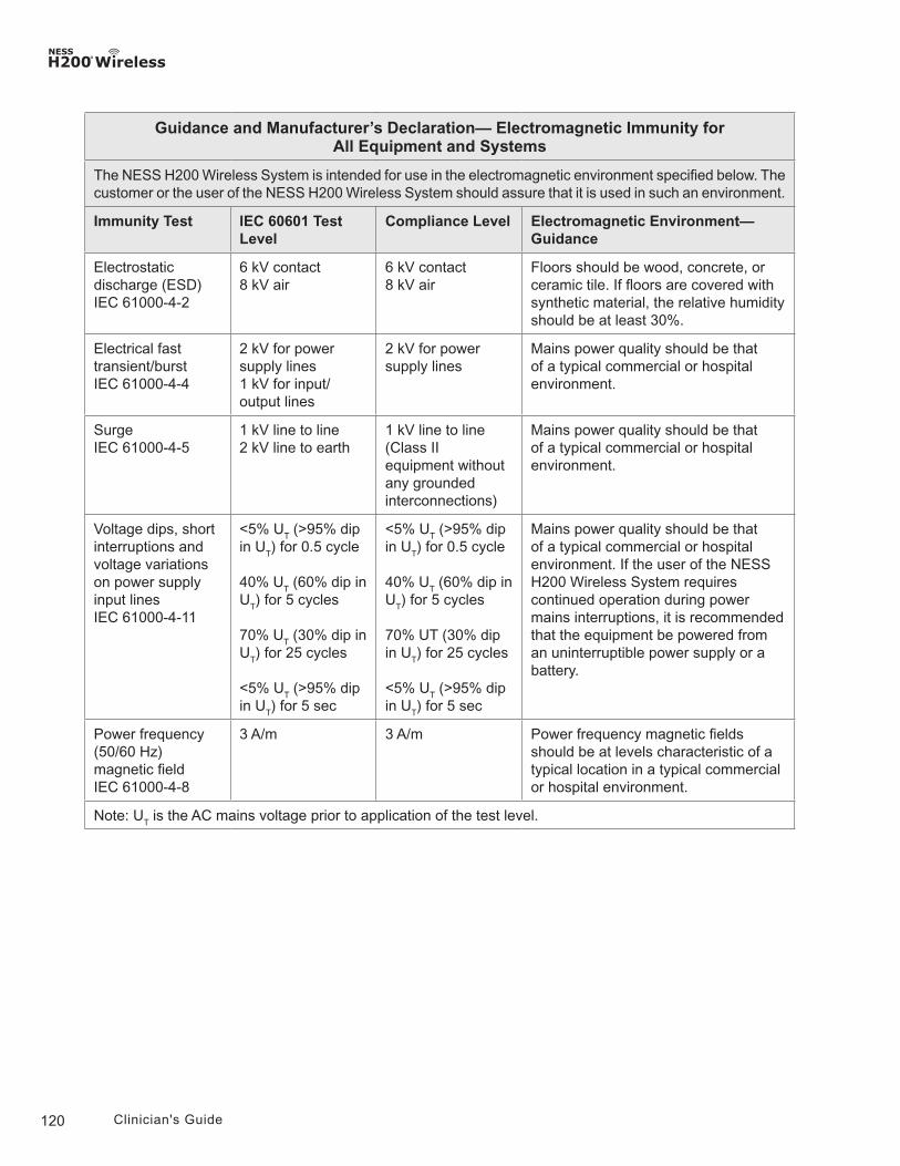
120 Clinician's Guide
Guidance and Manufacturer’s Declaration— Electromagnetic Immunity forAll Equipment and Systems
The NESS H200 Wireless System is intended for use in the electromagnetic environment specified below. The customer or the user of the NESS H200 Wireless System should assure that it is used in such an environment.
Immunity Test IEC 60601 Test Level
Compliance Level Electromagnetic Environment—Guidance
Electrostatic discharge (ESD)IEC 61000-4-2
6 kV contact8 kV air
6 kV contact8 kV air
Floors should be wood, concrete, or ceramic tile. If floors are covered with synthetic material, the relative humidity should be at least 30%.
Electrical fast transient/burstIEC 61000-4-4
2 kV for power supply lines1 kV for input/output lines
2 kV for power supply lines
Mains power quality should be that of a typical commercial or hospital environment.
SurgeIEC 61000-4-5
1 kV line to line2 kV line to earth
1 kV line to line(Class II equipment without any grounded interconnections)
Mains power quality should be that of a typical commercial or hospital environment.
Voltage dips, short interruptions and voltage variations on power supply input linesIEC 61000-4-11
<5% UT (>95% dip
in UT) for 0.5 cycle
40% UT (60% dip in
UT) for 5 cycles
70% UT (30% dip in
UT) for 25 cycles
<5% UT (>95% dip
in UT) for 5 sec
<5% UT (>95% dip
in UT) for 0.5 cycle
40% UT (60% dip in
UT) for 5 cycles
70% UT (30% dip in U
T) for 25 cycles
<5% UT (>95% dip
in UT) for 5 sec
Mains power quality should be that of a typical commercial or hospital environment. If the user of the NESS H200 Wireless System requires continued operation during power mains interruptions, it is recommended that the equipment be powered from an uninterruptible power supply or a battery.
Power frequency (50/60 Hz) magnetic fieldIEC 61000-4-8
3 A/m 3 A/m Power frequency magnetic fields should be at levels characteristic of a typical location in a typical commercial or hospital environment.
Note: UT is the AC mains voltage prior to application of the test level.
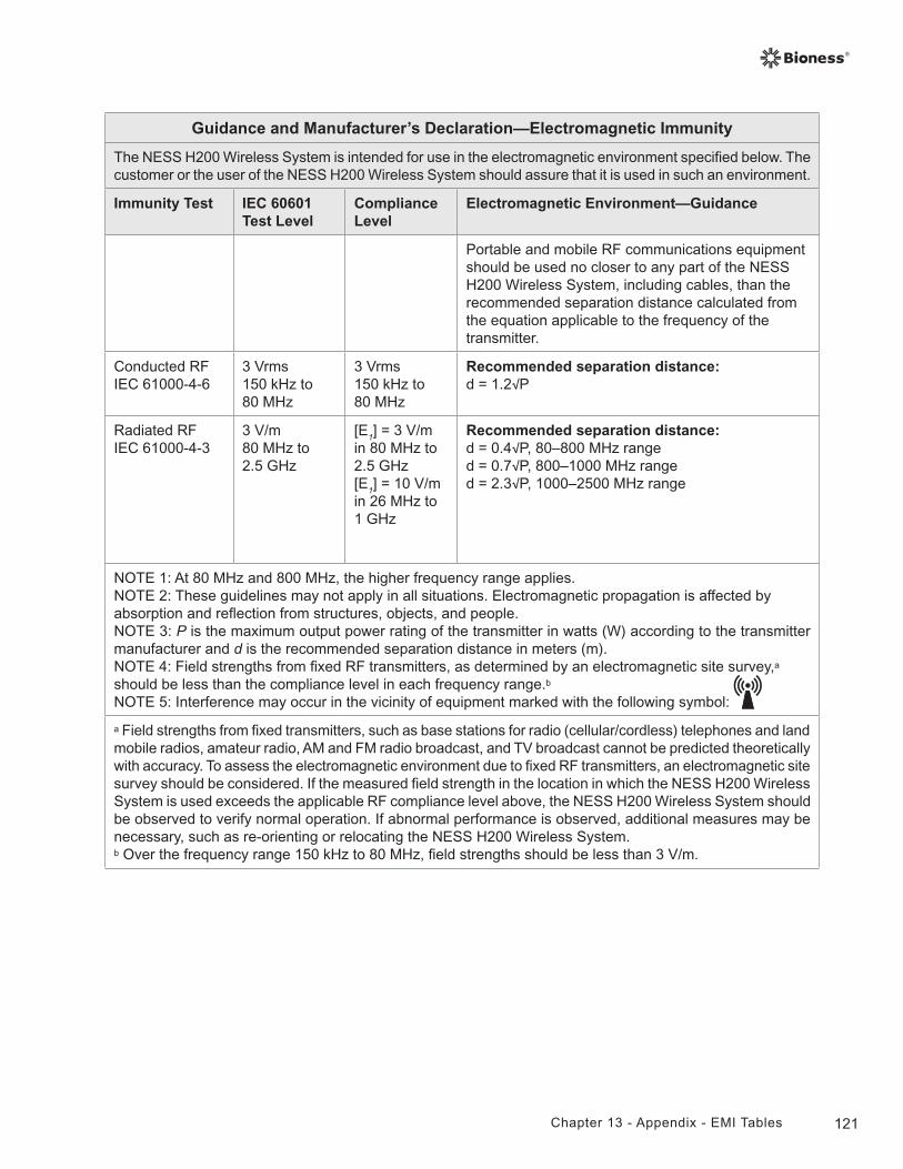
121Chapter 13 - Appendix - EMI Tables
Guidance and Manufacturer’s Declaration—Electromagnetic Immunity
The NESS H200 Wireless System is intended for use in the electromagnetic environment specified below. The customer or the user of the NESS H200 Wireless System should assure that it is used in such an environment.
Immunity Test IEC 60601 Test Level
Compliance Level
Electromagnetic Environment—Guidance
Portable and mobile RF communications equipment should be used no closer to any part of the NESS H200 Wireless System, including cables, than the recommended separation distance calculated from the equation applicable to the frequency of the transmitter.
Conducted RFIEC 61000-4-6
3 Vrms150 kHz to80 MHz
3 Vrms150 kHz to80 MHz
Recommended separation distance: d = 1.2√P
Radiated RFIEC 61000-4-3
3 V/m80 MHz to2.5 GHz
[E1] = 3 V/m in 80 MHz to2.5 GHz[E1] = 10 V/m in 26 MHz to1 GHz
Recommended separation distance: d = 0.4√P, 80–800 MHz ranged = 0.7√P, 800–1000 MHz ranged = 2.3√P, 1000–2500 MHz range
NOTE 1: At 80 MHz and 800 MHz, the higher frequency range applies.NOTE 2: These guidelines may not apply in all situations. Electromagnetic propagation is affected by absorption and reflection from structures, objects, and people.NOTE 3: P is the maximum output power rating of the transmitter in watts (W) according to the transmitter manufacturer and d is the recommended separation distance in meters (m). NOTE 4: Field strengths from fixed RF transmitters, as determined by an electromagnetic site survey,a should be less than the compliance level in each frequency range.b
NOTE 5: Interference may occur in the vicinity of equipment marked with the following symbol:
a Field strengths from fixed transmitters, such as base stations for radio (cellular/cordless) telephones and land mobile radios, amateur radio, AM and FM radio broadcast, and TV broadcast cannot be predicted theoretically with accuracy. To assess the electromagnetic environment due to fixed RF transmitters, an electromagnetic site survey should be considered. If the measured field strength in the location in which the NESS H200 Wireless System is used exceeds the applicable RF compliance level above, the NESS H200 Wireless System should be observed to verify normal operation. If abnormal performance is observed, additional measures may be necessary, such as re-orienting or relocating the NESS H200 Wireless System.b Over the frequency range 150 kHz to 80 MHz, field strengths should be less than 3 V/m.
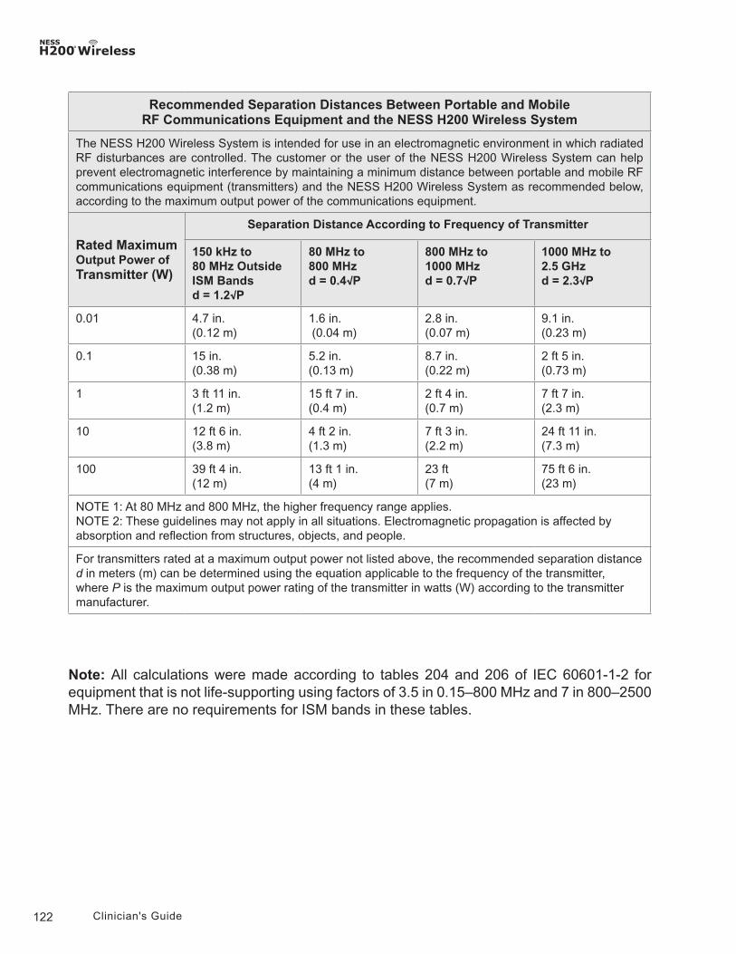
122 Clinician's Guide
Recommended Separation Distances Between Portable and MobileRF Communications Equipment and the NESS H200 Wireless System
The NESS H200 Wireless System is intended for use in an electromagnetic environment in which radiated RF disturbances are controlled. The customer or the user of the NESS H200 Wireless System can help prevent electromagnetic interference by maintaining a minimum distance between portable and mobile RF communications equipment (transmitters) and the NESS H200 Wireless System as recommended below, according to the maximum output power of the communications equipment.
Rated Maximum Output Power of Transmitter (W)
Separation Distance According to Frequency of Transmitter
150 kHz to80 MHz Outside ISM Bandsd = 1.2√P
80 MHz to800 MHzd = 0.4√P
800 MHz to1000 MHzd = 0.7√P
1000 MHz to2.5 GHzd = 2.3√P
0.01 4.7 in. (0.12 m)
1.6 in. (0.04 m)
2.8 in.(0.07 m)
9.1 in.(0.23 m)
0.1 15 in. (0.38 m)
5.2 in.(0.13 m)
8.7 in. (0.22 m)
2 ft 5 in. (0.73 m)
1 3 ft 11 in. (1.2 m)
15 ft 7 in. (0.4 m)
2 ft 4 in. (0.7 m)
7 ft 7 in. (2.3 m)
10 12 ft 6 in. (3.8 m)
4 ft 2 in.(1.3 m)
7 ft 3 in. (2.2 m)
24 ft 11 in.(7.3 m)
100 39 ft 4 in. (12 m)
13 ft 1 in.(4 m)
23 ft (7 m)
75 ft 6 in. (23 m)
NOTE 1: At 80 MHz and 800 MHz, the higher frequency range applies.NOTE 2: These guidelines may not apply in all situations. Electromagnetic propagation is affected by absorption and reflection from structures, objects, and people.
For transmitters rated at a maximum output power not listed above, the recommended separation distance d in meters (m) can be determined using the equation applicable to the frequency of the transmitter, where P is the maximum output power rating of the transmitter in watts (W) according to the transmitter manufacturer.
Note: All calculations were made according to tables 204 and 206 of IEC 60601-1-2 for equipment that is not life-supporting using factors of 3.5 in 0.15–800 MHz and 7 in 800–2500 MHz. There are no requirements for ISM bands in these tables.