Embed Size (px)
Citation preview
Product family data sheet
Copyright © 2012 Cree, Inc. All rights reserved. The information in this document is subject to change without notice. Cree®, the Cree logo and XLamp® are registered trademarks of Cree, Inc.
CLD
-DS
56 R
ev
0
cree® Xlamp® XP-e2 leds
Product descriPtion
The XLamp XP-e2 LeD builds on the
unprecedented performance of the
original XP-e by increasing lumen
output up to 20% while providing
a single die LeD point source for
precise optical control. The XP-
e2 LeD shares the same footprint
as the original XP-e, providing a
seamless upgrade path to more
lumens and/or greater efficiency
while shortening the design cycle
for existing XP customers.
XLamp XP-e2 LeDs are the ideal
choice for lighting applications
where high light output and
maximum efficacy are required,
such as LED retrofit lamps, outdoor
lighting, portable lighting, or indoor
directional lighting.
features
• Available in white, outdoor white,
80-CRI, 85-CRI and 90-CRI white
• ANSI-compatible chromaticity
bins
• Binned @ 85 °C
• Maximum drive current: 1 A
• Low thermal resistance: 9 °C/W
• Wide viewing angle: 110°
• Unlimited floor life at
≤ 30 °C/85% RH
• Reflow solderable - JEDEC J-STD-
020C compatible
• Electrically neutral thermal path
WW
W.
CR
EE.C
oM
/XLA
Mp
Cree, Inc.4600 Silicon Drive
Durham, NC 27703USA Tel: +1.919.313.5300
table of contents
Flux Characteristics .................... 2
Characteristics .......................... 3
Relative Spectral Power
Distribution............................... 3
Relative Flux vs. Junction
Temperature ............................. 4
electrical Characteristics ............. 4
Thermal Design ......................... 5
Relative Flux vs. Current ............ 5
Relative Chromaticity vs. Current
and Temperature - Warm White ... 6
Typical Spatial Distribution .......... 7
Reflow Soldering Characteristics .. 8
Notes ....................................... 9
Mechanical Dimensions..............10
Tape and Reel ..........................11
Packaging ................................12
Copyright © 2012 Cree, Inc. All rights reserved. The information in this document is subject to change without notice. Cree®, the Cree logo and XLamp® are registered trademarks of Cree, Inc.
2
xlamp xp-e2 leds
fluX characteristics (tJ = 85 °c)
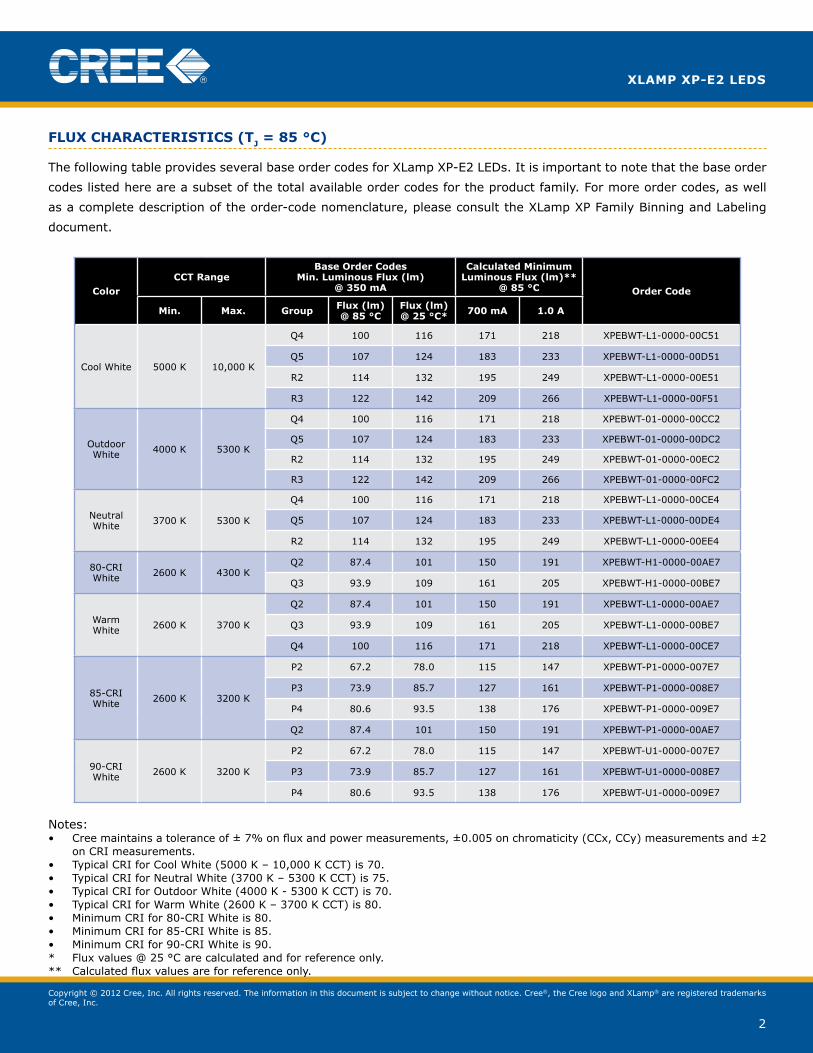
The following table provides several base order codes for XLamp XP-e2 LeDs. It is important to note that the base order
codes listed here are a subset of the total available order codes for the product family. For more order codes, as well
as a complete description of the order-code nomenclature, please consult the XLamp XP Family Binning and Labeling
document.
color
cct rangebase order codes
min. luminous flux (lm) @ 350 ma
calculated minimum luminous flux (lm)**
@ 85 °c order code
min. max. Group flux (lm) @ 85 °c
flux (lm) @ 25 °c* 700 ma 1.0 a
Cool White 5000 K 10,000 K
Q4 100 116 171 218 XpEBWT-L1-0000-00C51
Q5 107 124 183 233 XpEBWT-L1-0000-00D51
R2 114 132 195 249 XpEBWT-L1-0000-00E51
R3 122 142 209 266 XpEBWT-L1-0000-00F51
outdoor White 4000 K 5300 K
Q4 100 116 171 218 XpEBWT-01-0000-00CC2
Q5 107 124 183 233 XpEBWT-01-0000-00DC2
R2 114 132 195 249 XpEBWT-01-0000-00EC2
R3 122 142 209 266 XpEBWT-01-0000-00FC2
Neutral White 3700 K 5300 K
Q4 100 116 171 218 XpEBWT-L1-0000-00CE4
Q5 107 124 183 233 XpEBWT-L1-0000-00DE4
R2 114 132 195 249 XpEBWT-L1-0000-00EE4
80-CRI White 2600 K 4300 K
Q2 87.4 101 150 191 XpEBWT-H1-0000-00AE7
Q3 93.9 109 161 205 XpEBWT-H1-0000-00BE7
Warm White 2600 K 3700 K
Q2 87.4 101 150 191 XpEBWT-L1-0000-00AE7
Q3 93.9 109 161 205 XpEBWT-L1-0000-00BE7
Q4 100 116 171 218 XpEBWT-L1-0000-00CE7
85-CRI White 2600 K 3200 K
P2 67.2 78.0 115 147 XpEBWT-p1-0000-007E7
p3 73.9 85.7 127 161 XpEBWT-p1-0000-008E7
P4 80.6 93.5 138 176 XpEBWT-p1-0000-009E7
Q2 87.4 101 150 191 XpEBWT-p1-0000-00AE7
90-CRIWhite 2600 K 3200 K
P2 67.2 78.0 115 147 XpEBWT-U1-0000-007E7
p3 73.9 85.7 127 161 XpEBWT-U1-0000-008E7
P4 80.6 93.5 138 176 XpEBWT-U1-0000-009E7
Notes:• Cree maintains a tolerance of ± 7% on flux and power measurements, ±0.005 on chromaticity (CCx, CCy) measurements and ±2
on CRI measurements.• Typical CRI for Cool White (5000 K – 10,000 K CCT) is 70.• Typical CRI for Neutral White (3700 K – 5300 K CCT) is 75.• Typical CRI for outdoor White (4000 K - 5300 K CCT) is 70.• Typical CRI for Warm White (2600 K – 3700 K CCT) is 80.• Minimum CRI for 80-CRI White is 80.• Minimum CRI for 85-CRI White is 85.• Minimum CRI for 90-CRI White is 90.* Flux values @ 25 °C are calculated and for reference only.** Calculated flux values are for reference only.
Copyright © 2012 Cree, Inc. All rights reserved. The information in this document is subject to change without notice. Cree®, the Cree logo and XLamp® are registered trademarks of Cree, Inc.
3
xlamp xp-e2 leds
characteristics
characteristics unit minimum typical maximum
Thermal resistance, junction to solder point °C/W 9
Viewing angle (FWHM) degrees 110
Temperature coefficient of voltage mv/°C -2.3
ESD classification (HBM per Mil-Std-883D) Class 2
DC forward current mA 350 1000
Reverse voltage v -5
Forward voltage (@ 350 mA, 85 °C) v 2.9 3.75
Forward voltage (@ 700 mA, 85 °C) 3.05
Forward voltage (@ 1000 mA, 85 °C) 3.15
LeD junction temperature °C 150
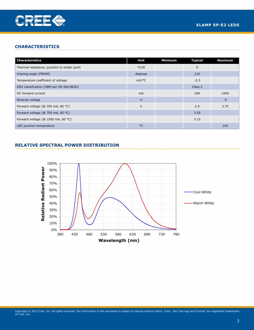
relative sPectral Power distributionRelative Spectral Power
0%
10%
20%
30%
40%
50%
60%
70%
80%
90%
100%
380 430 480 530 580 630 680 730 780
Rela
tive R
ad
ian
t P
ow
er
Wavelength (nm)
Cool White
Warm White
Copyright © 2012 Cree, Inc. All rights reserved. The information in this document is subject to change without notice. Cree®, the Cree logo and XLamp® are registered trademarks of Cree, Inc.
4
xlamp xp-e2 leds
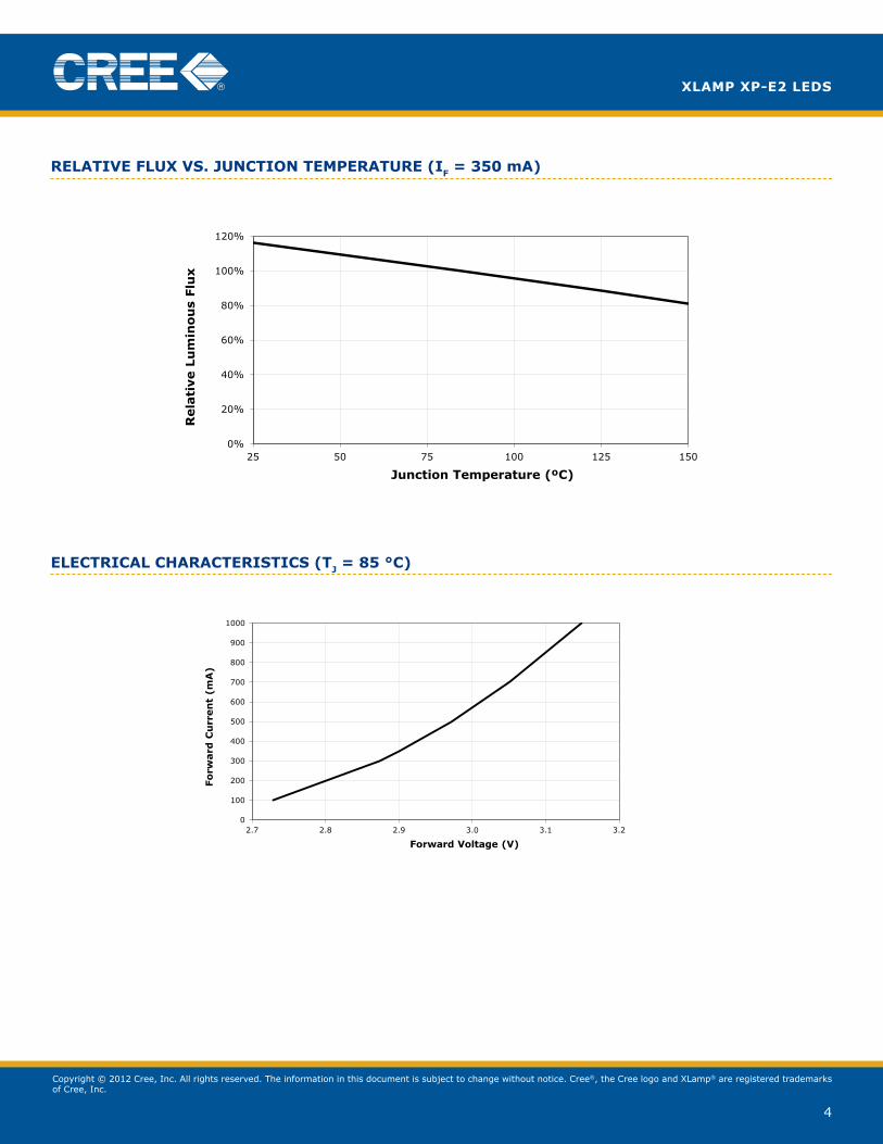
relative fluX vs. Junction temPerature (if = 350 ma)
electrical characteristics (tJ = 85 °c)
Relative Flux Output vs. Junction Temperature
0%
20%
40%
60%
80%
100%
120%
25 50 75 100 125 150
Rela
tive L
um
inou
s Flu
x
Junction Temperature (ºC)
Electrical Characteristics (Tj = 25ºC)
0
100
200
300
400
500
600
700
800
900
1000
2.7 2.8 2.9 3.0 3.1 3.2
Fo
rward
Cu
rren
t (m
A)
Forward Voltage (V)
Copyright © 2012 Cree, Inc. All rights reserved. The information in this document is subject to change without notice. Cree®, the Cree logo and XLamp® are registered trademarks of Cree, Inc.
5
xlamp xp-e2 leds
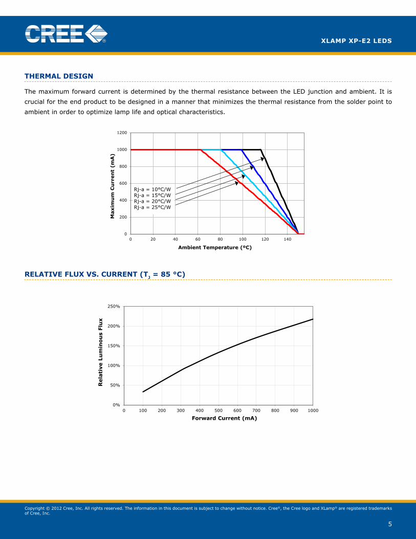
thermal desiGn
The maximum forward current is determined by the thermal resistance between the LeD junction and ambient. It is
crucial for the end product to be designed in a manner that minimizes the thermal resistance from the solder point to
ambient in order to optimize lamp life and optical characteristics.
relative fluX vs. current (tJ = 85 °c)
0
200
400
600
800
1000
1200
0 20 40 60 80 100 120 140
Maxim
um
Cu
rren
t (m
A)
Ambient Temperature (ºC)
Rj-a = 10°C/W Rj-a = 15°C/W Rj-a = 20°C/W Rj-a = 25°C/W
Relative Intensity vs. Current (Tj = 85ºC)
0%
50%
100%
150%
200%
250%
0 100 200 300 400 500 600 700 800 900 1000
Rela
tive L
um
ino
us
Flu
x
Forward Current (mA)
Copyright © 2012 Cree, Inc. All rights reserved. The information in this document is subject to change without notice. Cree®, the Cree logo and XLamp® are registered trademarks of Cree, Inc.
6
xlamp xp-e2 leds
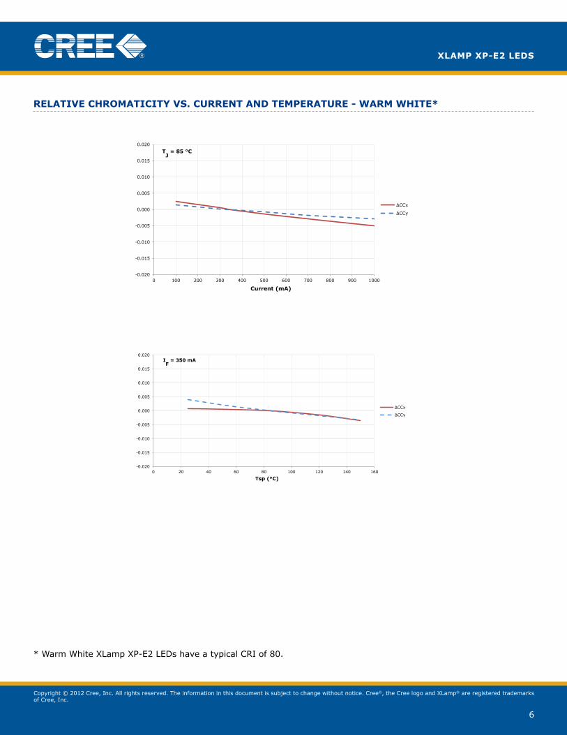
relative chromaticity vs. current and temPerature - warm white*
* Warm White XLamp Xp-E2 LEDs have a typical CRI of 80.
Relative Chromaticity Vs. Current, WW
-0.020
-0.015
-0.010
-0.005
0.000
0.005
0.010
0.015
0.020
0 100 200 300 400 500 600 700 800 900 1000
Current (mA)
ΔCCx
ΔCCy
TJ = 85 °C
Relative Chromaticity Vs. Temperature WW
-0.020
-0.015
-0.010
-0.005
0.000
0.005
0.010
0.015
0.020
0 20 40 60 80 100 120 140 160
Tsp (°C)
ΔCCx
ΔCCy
IF = 350 mA
Copyright © 2012 Cree, Inc. All rights reserved. The information in this document is subject to change without notice. Cree®, the Cree logo and XLamp® are registered trademarks of Cree, Inc.
7
xlamp xp-e2 leds
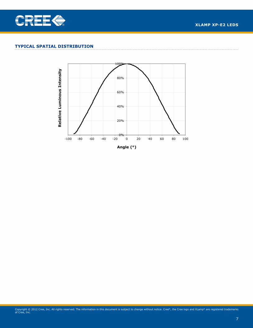
tyPical sPatial distribution
Typical Spatial Radiation Pattern
0%
20%
40%
60%
80%
100%
-100 -80 -60 -40 -20 0 20 40 60 80 100
Rela
tive L
um
ino
us
Inte
nsi
ty
Angle (°)
Copyright © 2012 Cree, Inc. All rights reserved. The information in this document is subject to change without notice. Cree®, the Cree logo and XLamp® are registered trademarks of Cree, Inc.
8
xlamp xp-e2 leds
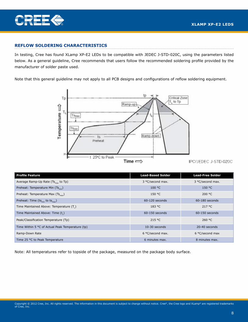
reflow solderinG characteristics
In testing, Cree has found XLamp Xp-E2 LEDs to be compatible with JEDEC J-STD-020C, using the parameters listed
below. As a general guideline, Cree recommends that users follow the recommended soldering profile provided by the
manufacturer of solder paste used.
Note that this general guideline may not apply to all pCB designs and configurations of reflow soldering equipment.
Profile Feature lead-based solder lead-free solder
Average Ramp-Up Rate (Tsmax to Tp) 3 °C/second max. 3 °C/second max.
preheat: Temperature Min (Tsmin) 100 °C 150 °C
preheat: Temperature Max (Tsmax) 150 °C 200 °C
preheat: Time (tsmin to tsmax) 60-120 seconds 60-180 seconds
Time Maintained Above: Temperature (TL) 183 °C 217 °C
Time Maintained Above: Time (tL) 60-150 seconds 60-150 seconds
peak/Classification Temperature (Tp) 215 °C 260 °C
Time Within 5 °C of Actual peak Temperature (tp) 10-30 seconds 20-40 seconds
Ramp-Down Rate 6 °C/second max. 6 °C/second max
Time 25 °C to Peak Temperature 6 minutes max. 8 minutes max.
Note: All temperatures refer to topside of the package, measured on the package body surface.
Copyright © 2012 Cree, Inc. All rights reserved. The information in this document is subject to change without notice. Cree®, the Cree logo and XLamp® are registered trademarks of Cree, Inc.
9
xlamp xp-e2 leds
notes
lumen maintenance ProjectionsCree now uses standardized IES LM-80-08 and TM-21-11 methods for collecting long-term data and extrapolating LED
lumen maintenance. For information on the specific LM-80 data sets available for this LED, refer to the public LM-80
results document at www.cree.com/xlamp_app_notes/LM80_results.
please read the XLamp Long-Term Lumen Maintenance application note at www.cree.com/xlamp_app_notes/XRE_
lumen_maintenance for more details on Cree’s lumen maintenance testing and forecasting. Please read the XLamp
Thermal Management application note at www.cree.com/xlamp_app_notes/thermal_management for details on how
thermal design, ambient temperature, and drive current affect the LeD junction temperature.
moisture sensitivityIn testing, Cree has found XLamp Xp-E2 LEDs to have unlimited floor life in conditions ≤ 30 ºC/85% relative humidity
(RH). Moisture testing included a 168-hour soak at 85 ºC/85% RH followed by 3 reflow cycles, with visual and electrical
inspections at each stage.
Cree recommends keeping XLamp LeDs in their sealed moisture-barrier packaging until immediately prior to use. Cree
also recommends returning any unused LeDS to the resealable moisture-barrier bag and closing the bag immediately
after use.
rohs complianceThe levels of environmentally sensitive, persistent biologically toxic (pBT), persistent organic pollutants (pop), or
otherwise restricted materials in this product are below the maximum concentration values (also referred to as the
threshold limits) permitted for such substances, or are used in an exempted application, in accordance with EU Directive
2002/95/EC on the restriction of the use of certain hazardous substances in electrical and electronic equipment (RoHS),
as amended through April 21, 2006.
vision advisory claimWARNING: Do not look at exposed lamp in operation. Eye injury can result. See LED Eye Safety at www.cree.com/
xlamp_app_notes/led_eye_safety.
Copyright © 2012 Cree, Inc. All rights reserved. The information in this document is subject to change without notice. Cree®, the Cree logo and XLamp® are registered trademarks of Cree, Inc.
10
xlamp xp-e2 leds
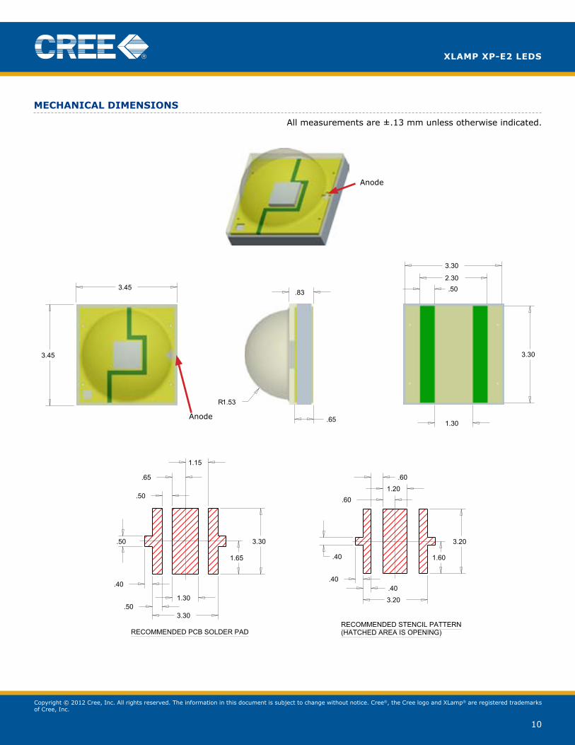
mechanical dimensions
All measurements are ±.13 mm unless otherwise indicated.
Anode
Anode
SIZE
TITLE
OF
REV.
SHEET
CDRAWING NO.
DATE
DATE
DATE
CHECK
FINAL PROTECTIVE FINISH
MATERIAL
APPROVED
DRAWN BY
THIRD ANGLE PROJECTION
SCALE
A
B
C
D
123456
6 5 4 3 2 1
A
B
C
D
Phone (919) 313-5300Fax (919) 313-5558
4600 Silicon DriveDurham, N.C 27703
UNAUTHORIZED PERSON WITHOUT THE WRITTEN CONSENTMAY NOT BE COPIED, REPRODUCED OR DISCLOSED TO ANY CONFIDENTIAL INFORMATION OF CREE, INC. THIS PLOT CONTAINED WITHIN ARE THE PROPRIETARY ANDCREE CONFIDENTIAL. THIS PLOT AND THE INFORMATION
OF CREE INC.
NOTICE
X° ± .5 °.XXX ± .25.XX ± .75.X ± 1.5
FOR SHEET METAL PARTS ONLY
.XX ± .25
.XXX ± .125X° ± .5 °
UNLESS OTHERWISE SPECIFIEDDIMENSIONS ARE IN
MILLIMETERS AND AFTER FINISH.TOLERANCE UNLESS SPECIFIED:
SURFACE FINISH: 1.6
.50
.50
.40
1.30
3.30
3.30
1.15
.65
1.65
.50
1.20
.60
.60
3.20
1.60
3.20
.40.40
.40
3.45
3.45
R1.53
.65
.83
3.30
.502.30
3.30
1.30
1/122.000
A2610-00029
OUTLINE DRAWING XPE G2
07/19/12D. CRONIN
REVISONS
REV DESCRIPTION BY DATE APP'D
RECOMMENDED PCB SOLDER PADRECOMMENDED STENCIL PATTERN(HATCHED AREA IS OPENING)
Copyright © 2012 Cree, Inc. All rights reserved. The information in this document is subject to change without notice. Cree®, the Cree logo and XLamp® are registered trademarks of Cree, Inc.
11
xlamp xp-e2 leds
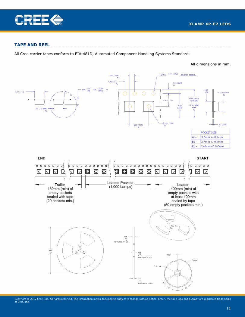
taPe and reel
All Cree carrier tapes conform to EIA-481D, Automated Component Handling Systems Standard.
All dimensions in mm.
Loaded Pockets(1,000 Lamps) Leader
400mm (min) ofempty pockets with
at least 100mmsealed by tape
(50 empty pockets min.)
Trailer160mm (min) ofempty pockets
sealed with tape(20 pockets min.)
STARTEND
Cathode Side
Anode Side(denoted by + and circle)
160.0
A
A
B
2.5±.1
SECTION A-A SCALE 2 : 1
1.5±.1
8.0±.1
4.0±.1
1.75±.10
12.0 .0+.3
DETAIL B SCALE 2 : 1
13mm7"
Cover Tape
Pocket Tape
User Feed Direction
User Feed Direction
SIZE
TITLE
OF
REV.
SHEET
CDRAWING NO.
DATE
DATE
DATE
CHECK
FINAL PROTECTIVE FINISH
MATERIAL
APPROVED
DRAWN BY
THIRD ANGLE PROJECTION
X° ± .5 °.XXX ± .010.XX ± .03.X ± .06
FOR SHEET METAL PARTS ONLY
.XX ± .01
.XXX ± .005X° ± .5 °
UNLESS OTHERWISE SPECIFIEDDIMENSIONS ARE IN INCHES
AND AFTER FINISH.TOLERANCE UNLESS SPECIFIED:
SCALE
A
B
C
D
123456
6 5 4 3 2 1
A
B
C
D
Phone (919) 313-5300Fax (919) 313-5558
4600 Silicon DriveDurham, N.C 27703
UNAUTHORIZED PERSON WITHOUT THE WRITTEN CONSENTMAY NOT BE COPIED, REPRODUCED OR DISCLOSED TO ANYCONFIDENTIAL INFORMATION OF CREE, INC. THIS PLOTCONTANED WITHIN ARE THE PROPRIETARY ANDCREE CONFIDENTIAL. THIS PLOT AND THE INFORMATION
OF CREE INC.
NOTICE
SURFACE FINISH: 63
330+.25-.75
12.4+1.0-.5MEASURED AT EDGE
16.4+0.2.0MEASURED AT HUB
12.4+.2
.0MEASURED AT HUB
±.213.1
1.9±.4
±.421
60° 60°
1/10.500
A2400-00009
REEL, 13" X 12MM, 3 PIECE SNAP
-
ANTI-STATIC HIPS
----
----
09/29/09D. CRONIN
2400-00009INDEX QTY ITEM COMMENTS
1 1 2400-00009-CORE2 2 2400-00009-REEL
REVISONS
REV DESCRIPTION BY DATE APP'D
.30 [.012]T
Ao3.7 +/-0.1mm
+.10 +.00392.46 .096 Ko-.00[ -.0000]
3.7 +/-0.1mmBo
P22.00 [.079]
Po4.00 [.157]
10.25[.404]
E2
1.50 +.10 +.0039 -.00[.0591-.0000]Do
4.39 [.173]
4.39[.173]
7.3 °
12.00 [.472]NOMINAL
12.30 [.484]
MAXW
1.75 [.069]E1
5.50 [.217]F
1.50 [.059] D18.00 [.315]
P
POCKET SIZE
Ao - 3.7mm +/-0.1mm
Bo - 3.7mm +/-0.1mm
Ko - 2.46mm +0.1/-0mm
Copyright © 2012 Cree, Inc. All rights reserved. The information in this document is subject to change without notice. Cree®, the Cree logo and XLamp® are registered trademarks of Cree, Inc.
12
xlamp xp-e2 leds
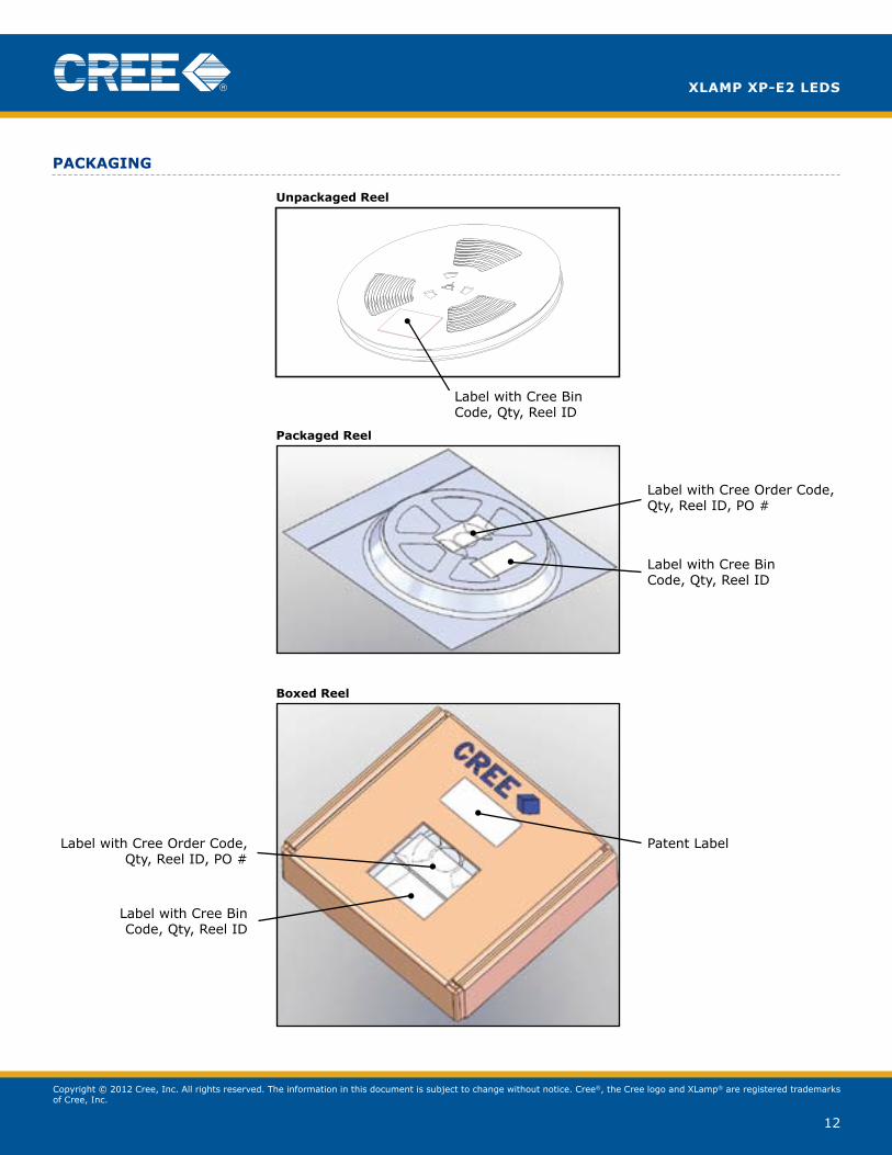
PackaGinG
Label with Cree Bin Code, Qty, Lot #
Label with Cree Bin Code, Qty, Lot #
Vacuum-Sealed Moisture Barrier Bag
Dessicant (inside bag)
Humidity Indicator Card (inside bag)
Patent Label
Label with Customer Order Code, Qty, Reel ID, PO #
Patent Label
Label with Cree Bin Code, Qty, Reel ID
Label with Cree Bin Code, Qty, Reel ID
Label with Cree Order Code, Qty, Reel ID, PO #
Label with Cree Order Code, Qty, Reel ID, PO #
Label with Cree Bin Code, Qty, Reel ID
Unpackaged Reel
Packaged Reel
Boxed Reel