Embed Size (px)
Citation preview
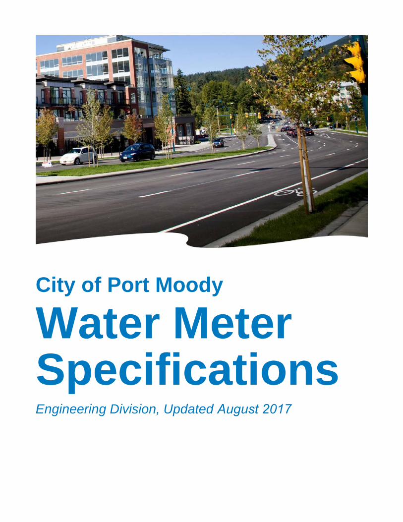
City of Port Moody
Water Meter Specifications Engineering Division, Updated August 2017
City of Port Moody Water Meter Specifications (Updated August 2017) 2
City of Port Moody Water Meter Specifications
1. Preamble ........................................................................................................................................... 3
2. Definitions .......................................................................................................................................... 3
3. Services to be Metered ...................................................................................................................... 3
4. Location of Meters ............................................................................................................................. 4
5. Meter Types ....................................................................................................................................... 4
6. Registers ........................................................................................................................................... 5
7. Meter Selection .................................................................................................................................. 5
8. Dedicated Fire Services ..................................................................................................................... 6
9. Combined Fire Domestic Services ..................................................................................................... 6
10. Installation Requirements ................................................................................................................. 6
11. Materials .......................................................................................................................................... 8
12. Inspection Procedure ..................................................................................................................... 10
13. Temporary Water Services ............................................................................................................ 10
14. Water Meter Specification Detailed Drawings ............................................................................... 11
Typical Service Installation WM-1
16-25mm Displacement Meter WM-2
16-25mm Displacement Meter WM-2A
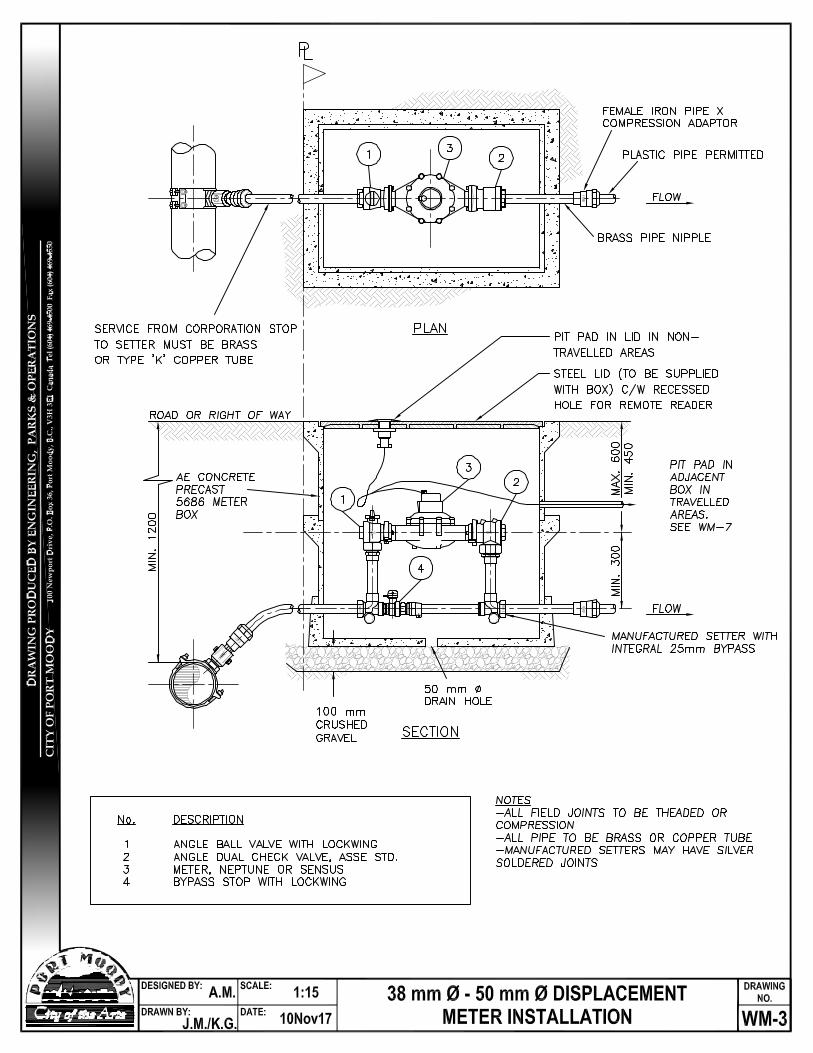
38-50mm Displacement Meter WM-3
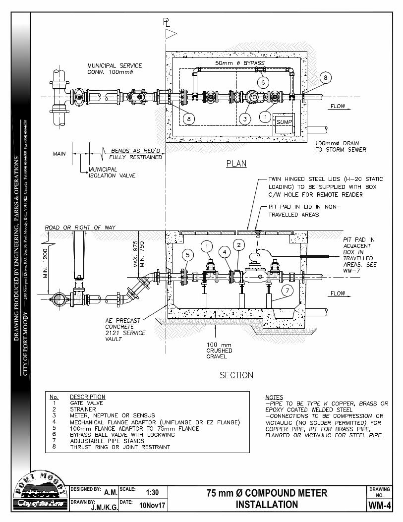
75mm Compound Meter WM-4
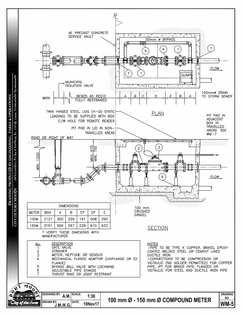
100-150mm Compound Meter WM-5
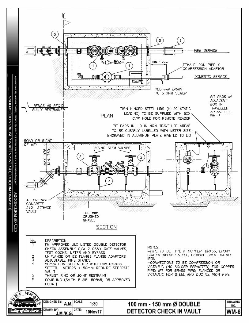
100-150mm Double Detector Check Meter WM-6
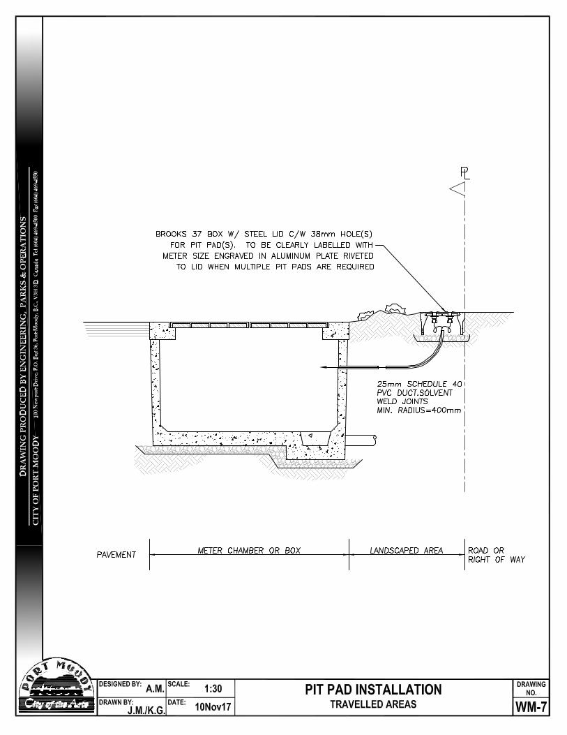
Pit Pad Installation, Traveled Areas WM-7
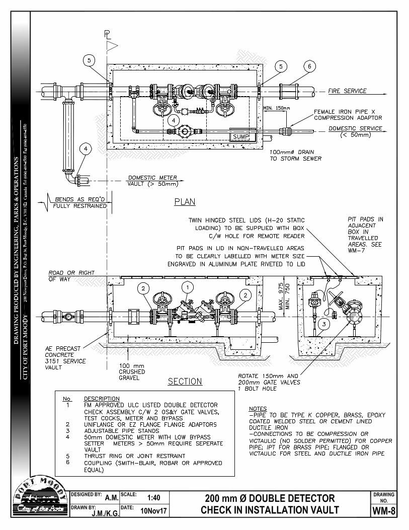
200mm Double Detector Check Meter WM-8
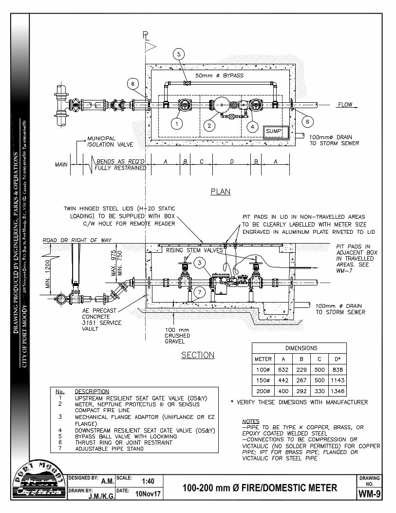
150mm Fire/Domestic Meter WM-9
Please note that the City of Port Moody’s Water Meter Specifications is an organic document, and may change from time to time. Find the most recent copy at www.portmoody.ca/engineering. While on the site, you can also sign up for an email notification of any changes to this document.
3
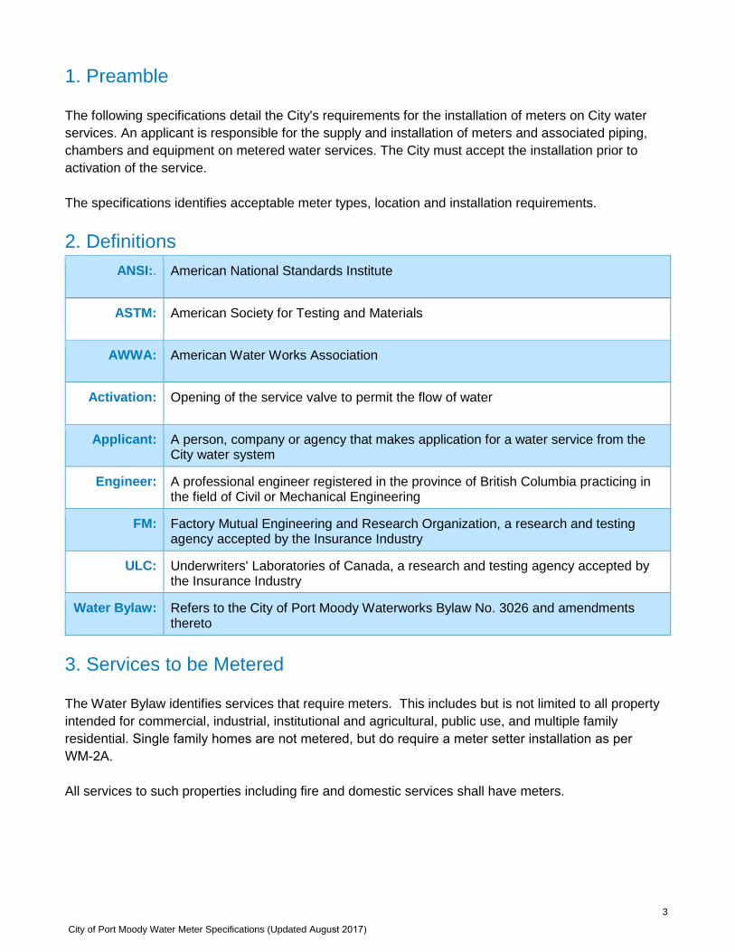
1. Preamble
The following specifications detail the City's requirements for the installation of meters on City water services. An applicant is responsible for the supply and installation of meters and associated piping, chambers and equipment on metered water services. The City must accept the installation prior to activation of the service.
The specifications identifies acceptable meter types, location and installation requirements.
2. DefinitionsANSI:. American National Standards Institute
ASTM: American Society for Testing and Materials
AWWA: American Water Works Association
Activation: Opening of the service valve to permit the flow of water
Applicant: A person, company or agency that makes application for a water service from the City water system
Engineer: A professional engineer registered in the province of British Columbia practicing in the field of Civil or Mechanical Engineering
FM: Factory Mutual Engineering and Research Organization, a research and testing agency accepted by the Insurance Industry
ULC: Underwriters' Laboratories of Canada, a research and testing agency accepted by the Insurance Industry
Water Bylaw: Refers to the City of Port Moody Waterworks Bylaw No. 3026 and amendments thereto
3. Services to be Metered
The Water Bylaw identifies services that require meters. This includes but is not limited to all property intended for commercial, industrial, institutional and agricultural, public use, and multiple family residential. Single family homes are not metered, but do require a meter setter installation as per WM-2A.
All services to such properties including fire and domestic services shall have meters.
City of Port Moody Water Meter Specifications (Updated August 2017)
City of Port Moody Water Meter Specifications (Updated August 2017) 4
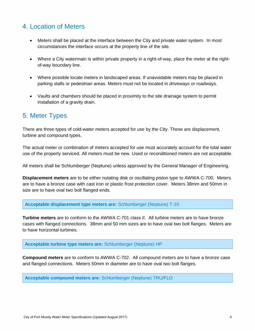
4. Location of Meters
• Meters shall be placed at the interface between the City and private water system. In most circumstances the interface occurs at the property line of the site.
• Where a City watermain is within private property in a right-of-way, place the meter at the right-of-way boundary line.
• Where possible locate meters in landscaped areas. If unavoidable meters may be placed in parking stalls or pedestrian areas. Meters must not be located in driveways or roadways.
• Vaults and chambers should be placed in proximity to the site drainage system to permit installation of a gravity drain.
5. Meter Types
There are three types of cold-water meters accepted for use by the City. These are displacement, turbine and compound types.
The actual meter or combination of meters accepted for use must accurately account for the total water use of the property serviced. All meters must be new. Used or reconditioned meters are not acceptable.
All meters shall be Schlumberger (Neptune) unless approved by the General Manager of Engineering.
Displacement meters are to be either nutating disk or oscillating piston type to AWWA C-700. Meters are to have a bronze case with cast iron or plastic frost protection cover. Meters 38mm and 50mm in size are to have oval two bolt flanged ends.
Acceptable displacement type meters are: Schlumberger (Neptune) T-10
Turbine meters are to conform to the AWWA C-701 class II. All turbine meters are to have bronze cases with flanged connections. 38mm and 50 mm sizes are to have oval two bolt flanges. Meters are to have horizontal turbines.
Acceptable turbine type meters are: Schlumberger (Neptune) HP
Compound meters are to conform to AWWA C-702. All compound meters are to have a bronze case and flanged connections. Meters 50mm in diameter are to have oval two bolt flanges.
Acceptable compound meters are: Schlumberger (Neptune) TRU/FLO
5
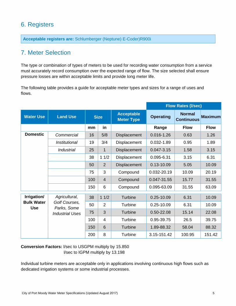
6. Registers
Acceptable registers are: Schlumberger (Neptune) E-Coder)R900i
7. Meter Selection
The type or combination of types of meters to be used for recording water consumption from a service must accurately record consumption over the expected range of flow. The size selected shall ensure pressure losses are within acceptable limits and provide long meter life.
The following table provides a guide for acceptable meter types and sizes for a range of uses and flows.
Flow Rates (l/sec)
Water Use Land Use Size Acceptable Meter Type Operating Normal
Continuous Maximum
mm in Range Flow Flow Domestic Commercial 16 5/8 Displacement 0.016-1.26 0.63 1.26
Institutional 19 3/4 Displacement 0.032-1.89 0.95 1.89
Industrial 25 1 Displacement 0.047-3.15 1.58 3.15
38 1 1/2 Displacement 0.095-6.31 3.15 6.31
50 2 Displacement 0.13-10.09 5.05 10.09
75 3 Compound 0.032-20.19 10.09 20.19
100 4 Compound 0.047-31.55 15.77 31.55
150 6 Compound 0.095-63.09 31.55 63.09
Irrigation/ Bulk Water
Use
Agricultural, Golf Courses, Parks, Some
Industrial Uses
38 1 1/2 Turbine 0.25-10.09 6.31 10.09
50 2 Turbine 0.25-10.09 6.31 10.09
75 3 Turbine 0.50-22.08 15.14 22.08
100 4 Turbine 0.95-39.75 26.5 39.75
150 6 Turbine 1.89-88.32 58.04 88.32
200 8 Turbine 3.15-151.42 100.95 151.42
Conversion Factors: l/sec to USGPM multiply by 15.850 l/sec to IGPM multiply by 13.198
Individual turbine meters are acceptable only in applications involving continuous high flows such as dedicated irrigation systems or some industrial processes.
City of Port Moody Water Meter Specifications (Updated August 2017)
City of Port Moody Water Meter Specifications (Updated August 2017) 6
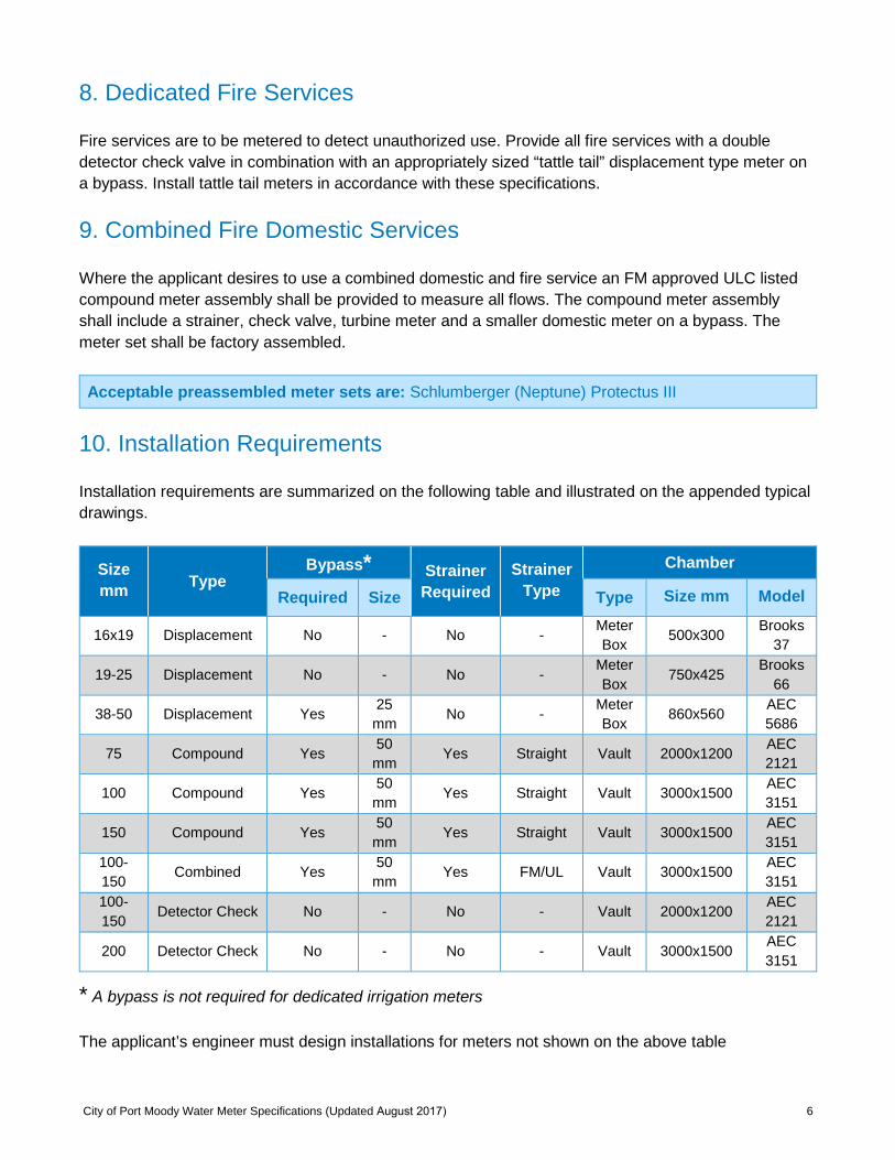
8. Dedicated Fire Services
Fire services are to be metered to detect unauthorized use. Provide all fire services with a double detector check valve in combination with an appropriately sized “tattle tail” displacement type meter on a bypass. Install tattle tail meters in accordance with these specifications.
9. Combined Fire Domestic Services
Where the applicant desires to use a combined domestic and fire service an FM approved ULC listed compound meter assembly shall be provided to measure all flows. The compound meter assembly shall include a strainer, check valve, turbine meter and a smaller domestic meter on a bypass. The meter set shall be factory assembled.
Acceptable preassembled meter sets are: Schlumberger (Neptune) Protectus III
10. Installation Requirements
Installation requirements are summarized on the following table and illustrated on the appended typical drawings.
Size mm Type
Bypass* Strainer Required
Strainer Type
Chamber
Required Size Type Size mm Model
16x19 Displacement No - No - Meter Box 500x300 Brooks
37
19-25 Displacement No - No - Meter Box 750x425
Brooks 66
38-50 Displacement Yes 25 mm No - Meter
Box 860x560 AEC 5686
75 Compound Yes 50 mm Yes Straight Vault 2000x1200 AEC
2121
100 Compound Yes 50 mm Yes Straight Vault 3000x1500 AEC
3151
150 Compound Yes 50 mm Yes Straight Vault 3000x1500 AEC
3151 100-150 Combined Yes 50
mm Yes FM/UL Vault 3000x1500 AEC 3151
100-150 Detector Check No - No - Vault 2000x1200 AEC
2121
200 Detector Check No - No - Vault 3000x1500 AEC 3151
* A bypass is not required for dedicated irrigation meters
The applicant’s engineer must design installations for meters not shown on the above table
7
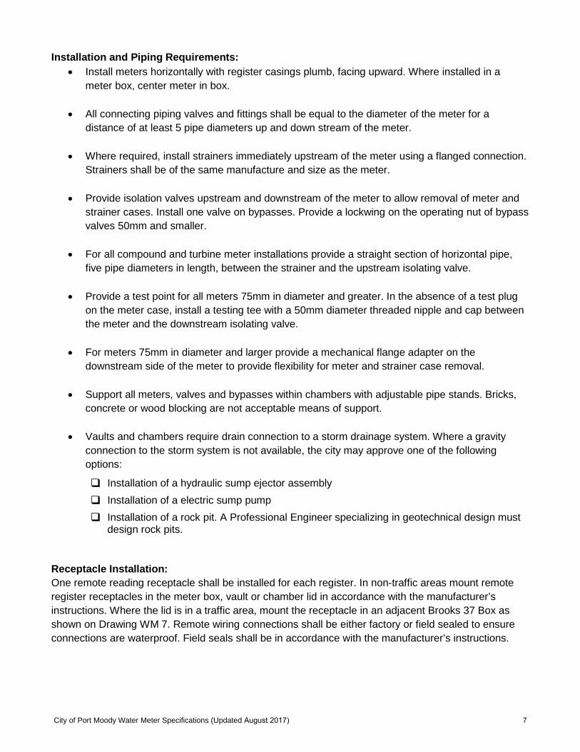
Installation and Piping Requirements: • Install meters horizontally with register casings plumb, facing upward. Where installed in a
meter box, center meter in box.
• All connecting piping valves and fittings shall be equal to the diameter of the meter for adistance of at least 5 pipe diameters up and down stream of the meter.
• Where required, install strainers immediately upstream of the meter using a flanged connection.Strainers shall be of the same manufacture and size as the meter.
• Provide isolation valves upstream and downstream of the meter to allow removal of meter andstrainer cases. Install one valve on bypasses. Provide a lockwing on the operating nut of bypassvalves 50mm and smaller.
• For all compound and turbine meter installations provide a straight section of horizontal pipe,five pipe diameters in length, between the strainer and the upstream isolating valve.
• Provide a test point for all meters 75mm in diameter and greater. In the absence of a test plugon the meter case, install a testing tee with a 50mm diameter threaded nipple and cap betweenthe meter and the downstream isolating valve.
• For meters 75mm in diameter and larger provide a mechanical flange adapter on thedownstream side of the meter to provide flexibility for meter and strainer case removal.
• Support all meters, valves and bypasses within chambers with adjustable pipe stands. Bricks,concrete or wood blocking are not acceptable means of support.
• Vaults and chambers require drain connection to a storm drainage system. Where a gravityconnection to the storm system is not available, the city may approve one of the followingoptions:
Installation of a hydraulic sump ejector assembly
Installation of a electric sump pump
Installation of a rock pit. A Professional Engineer specializing in geotechnical design mustdesign rock pits.
Receptacle Installation: One remote reading receptacle shall be installed for each register. In non-traffic areas mount remote register receptacles in the meter box, vault or chamber lid in accordance with the manufacturer’s instructions. Where the lid is in a traffic area, mount the receptacle in an adjacent Brooks 37 Box as shown on Drawing WM 7. Remote wiring connections shall be either factory or field sealed to ensure connections are waterproof. Field seals shall be in accordance with the manufacturer’s instructions.
City of Port Moody Water Meter Specifications (Updated August 2017)
City of Port Moody Water Meter Specifications (Updated August 2017) 8
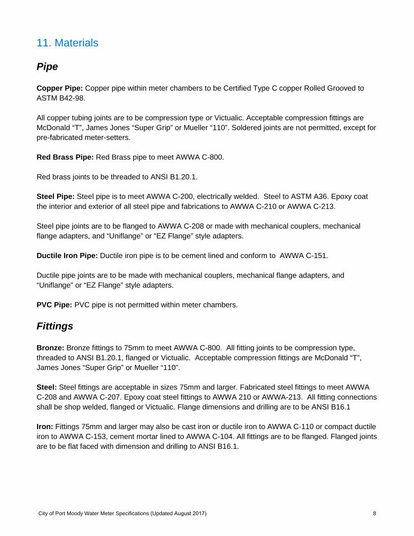
11. Materials
Pipe
Copper Pipe: Copper pipe within meter chambers to be Certified Type C copper Rolled Grooved to ASTM B42-98.
All copper tubing joints are to be compression type or Victualic. Acceptable compression fittings are McDonald “T”, James Jones “Super Grip” or Mueller “110”. Soldered joints are not permitted, except for pre-fabricated meter-setters.
Red Brass Pipe: Red Brass pipe to meet AWWA C-800.
Red brass joints to be threaded to ANSI B1.20.1.
Steel Pipe: Steel pipe is to meet AWWA C-200, electrically welded. Steel to ASTM A36. Epoxy coat the interior and exterior of all steel pipe and fabrications to AWWA C-210 or AWWA C-213.
Steel pipe joints are to be flanged to AWWA C-208 or made with mechanical couplers, mechanical flange adapters, and “Uniflange” or “EZ Flange” style adapters.
Ductile Iron Pipe: Ductile iron pipe is to be cement lined and conform to AWWA C-151.
Ductile pipe joints are to be made with mechanical couplers, mechanical flange adapters, and “Uniflange” or “EZ Flange” style adapters.
PVC Pipe: PVC pipe is not permitted within meter chambers.
Fittings
Bronze: Bronze fittings to 75mm to meet AWWA C-800. All fitting joints to be compression type, threaded to ANSI B1.20.1, flanged or Victualic. Acceptable compression fittings are McDonald “T”, James Jones “Super Grip” or Mueller “110”.
Steel: Steel fittings are acceptable in sizes 75mm and larger. Fabricated steel fittings to meet AWWA C-208 and AWWA C-207. Epoxy coat steel fittings to AWWA 210 or AWWA-213. All fitting connectionsshall be shop welded, flanged or Victualic. Flange dimensions and drilling are to be ANSI B16.1
Iron: Fittings 75mm and larger may also be cast iron or ductile iron to AWWA C-110 or compact ductile iron to AWWA C-153, cement mortar lined to AWWA C-104. All fittings are to be flanged. Flanged joints are to be flat faced with dimension and drilling to ANSI B16.1.
City of Port Moody Water Meter Specifications (Updated August 2017) 9
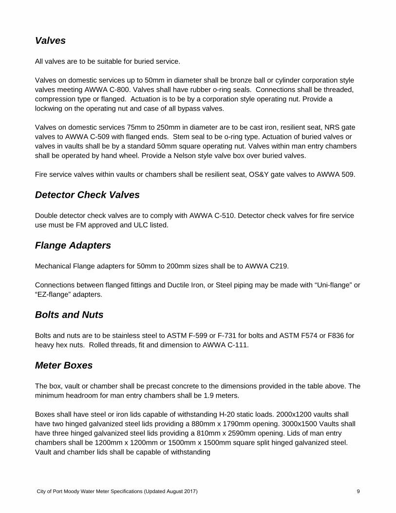
Valves
All valves are to be suitable for buried service.
Valves on domestic services up to 50mm in diameter shall be bronze ball or cylinder corporation style valves meeting AWWA C-800. Valves shall have rubber o-ring seals. Connections shall be threaded, compression type or flanged. Actuation is to be by a corporation style operating nut. Provide a lockwing on the operating nut and case of all bypass valves.
Valves on domestic services 75mm to 250mm in diameter are to be cast iron, resilient seat, NRS gate valves to AWWA C-509 with flanged ends. Stem seal to be o-ring type. Actuation of buried valves or valves in vaults shall be by a standard 50mm square operating nut. Valves within man entry chambers shall be operated by hand wheel. Provide a Nelson style valve box over buried valves.
Fire service valves within vaults or chambers shall be resilient seat, OS&Y gate valves to AWWA 509.
Detector Check Valves
Double detector check valves are to comply with AWWA C-510. Detector check valves for fire service use must be FM approved and ULC listed.
Flange Adapters
Mechanical Flange adapters for 50mm to 200mm sizes shall be to AWWA C219.
Connections between flanged fittings and Ductile Iron, or Steel piping may be made with “Uni-flange” or “EZ-flange” adapters.
Bolts and Nuts
Bolts and nuts are to be stainless steel to ASTM F-599 or F-731 for bolts and ASTM F574 or F836 for heavy hex nuts. Rolled threads, fit and dimension to AWWA C-111.
Meter Boxes
The box, vault or chamber shall be precast concrete to the dimensions provided in the table above. The minimum headroom for man entry chambers shall be 1.9 meters.
Boxes shall have steel or iron lids capable of withstanding H-20 static loads. 2000x1200 vaults shall have two hinged galvanized steel lids providing a 880mm x 1790mm opening. 3000x1500 Vaults shall have three hinged galvanized steel lids providing a 810mm x 2590mm opening. Lids of man entry chambers shall be 1200mm x 1200mm or 1500mm x 1500mm square split hinged galvanized steel. Vault and chamber lids shall be capable of withstanding
City of Port Moody Water Meter Specifications (Updated August 2017) 10
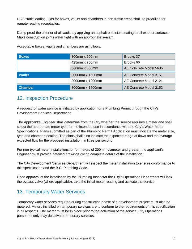
H-20 static loading. Lids for boxes, vaults and chambers in non-traffic areas shall be predrilled forremote reading receptacles.
Damp proof the exterior of all vaults by applying an asphalt emulsion coating to all exterior surfaces. Make construction joints water tight with an appropriate sealant.
Acceptable boxes, vaults and chambers are as follows:
Boxes 300mm x 500mm Brooks 37
425mm x 750mm Brooks 66
560mm x 860mm AE Concrete Model 5686
Vaults 3000mm x 1500mm AE Concrete Model 3151
2000mm x 1200mm AE Concrete Model 2121
Chamber 3000mm x 1500mm AE Concrete Model 3152
12. Inspection Procedure
A request for water service is initiated by application for a Plumbing Permit through the City’s Development Services Department.
The Applicant’s Engineer shall determine from the City whether the service requires a meter and shall select the appropriate meter type for the intended use in accordance with the City's Water Meter Specifications. Plans submitted as part of the Plumbing Permit Application must indicate the meter size, type and chamber location. The plans shall also indicate the expected range of flows and the average expected flow for the proposed installation, in litres per second.
For non-typical meter installations, or for meters of 200mm diameter and greater, the applicant’s Engineer must provide detailed drawings giving complete details of the installation.
The City Development Services Department will inspect the meter installation to ensure conformance to this specification and the B.C. Plumbing Code.
Upon approval of the installation by the Plumbing Inspector the City’s Operations Department will lock the bypass valve (where applicable), take the initial meter reading and activate the service.
13. Temporary Water Services
Temporary water services required during construction phase of a development project must also be metered. Meters installed on temporary services are to conform to the requirements of this specification in all respects. The meter must be in place prior to the activation of the service. City Operations personnel only may deactivate temporary services.
City of Port Moody Water Meter Specifications (Updated August 2017) 11
14. Water Meter SpecificationDetailed Drawings
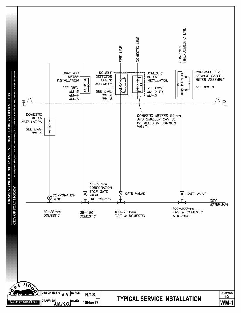
DOMESTIC METER
INSTALLATION
SEE DWG.
fr_ L\ __
WM-3 WM-4 WM-5
DOMESTIC METER
INSTALLATION
SEE DWG. WM-2
CORPORATION STOP
19-25mmDOMESTIC
Lu 2: :J
Lu (..)2: i== :J !fl Lu ::!E 0::: 0 G: a
DOUBLE r-- -------- ---, DOMESTICDETECTOR
I I METER CHECK I I INSTALLATION
ASSEMBLY I I I I SEE DWG.
SEE DWG. I I WM-2 TOWM-6 L
-- --------�-.J WM-5WM-8
----- --- -----
Lu 2: :J
(..)i== !fl
�::!E 2: 0_a CD',.
::!EW oQ; (..) LL.
COMBINED FIRE SERVICE RATED METER ASSEMBLY
SEE WM-9
_ _____ _D fr_
DOMESTIC METERS 50mm AND SMALLER CAN BE INSTALLED IN COMMON
VAULT.
38-SOmmCORPORATIONSTOP GATEVALVE100-150mm
38-150DOMESTIC
GATE VALVE
100-200mmFIRE & DOMESTIC
GATE VALVE
100-200mmFIRE & DOMESTICALTERNATE
CITY WATERMAIN
:..c- . M (J
DRAWING
., 0
-'��� DESIGNEDBY: A.M. SCALE: N.T.S. "'""""'Al ",..""·�City of the Arts DRAWN ev:
I DATE: 1ONov17 J.M./K.G.
I Tl"'l\,AL "Cl'{Yl\,E INSTALLATION WM-1
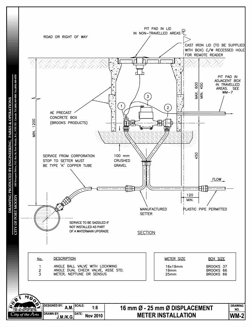
ROAD OR RIGHT OF WAY
PIT PAD IN LID IN NON-TRAVELLED AREAS Fr_
�T IRON LID (TO BE SUPPLIED
I WITH BOX) C/W RECESSED HOLEFOR REMOTE READER
)/ )/ )/ )/ )/ )/ )/ )/ )/ ..
�: '. ... · )/ )/ )/ " »' »' »' »' »' »' »' � � :·/:�--�""'e:=;::T"���-. � �-{.�. »'« «<«<«
0 0 N
/ / // / // / // / //, //, //, //, )/. :�:<� }/ I � � I
AE PRECAST CONCRETE BOX (BROOKS PRODUCTS)
SERVICE FROM CORPORATION STOP TO SETTER MUST BE TYPE 'K' COPPER TUBE
, . \: I
100 mm CRUSHED GRAVEL
.:;. I ,· . .
Oo 0 lf) co """
><z.<( -::E ::E
0 lf)
� � I
PIT PAD IN
ADJACENT BOX IN TRAVELLED AREAS. SEE
WM-7
FLOW
MANUFACTURED SETTER
FLASTIC PIPE PERMITTED
1 2 3
DESCRIPTION
ANGLE BALL VALVE WITH LOCKWING ANGLE DUAL CHECK VALVE, ASSE STD. METER, NEPTUNE OR SENSUS
SECTION
METER SIZE
16x19mm 19mm 25mm
BOX SIZE
BROOKS 37 BROOKS 66 BROOKS 66
�"1 �() ���,'\-r--------.......... ----,-----------,--------------------,------1��� oEslGNEoev:
A.M. scALE:
1:s 16 mm 0 - 25 mm 0 DISPLACEMENT 0���NG
City of the Arts DRAWN BY: DATE: Nov2010 METER INSTALLATION J.M./K.G. WM-2
SERVICE TO BE SADDLED IF NOT INSTALLED AS PART OF A WATERMAIN UPGRADE
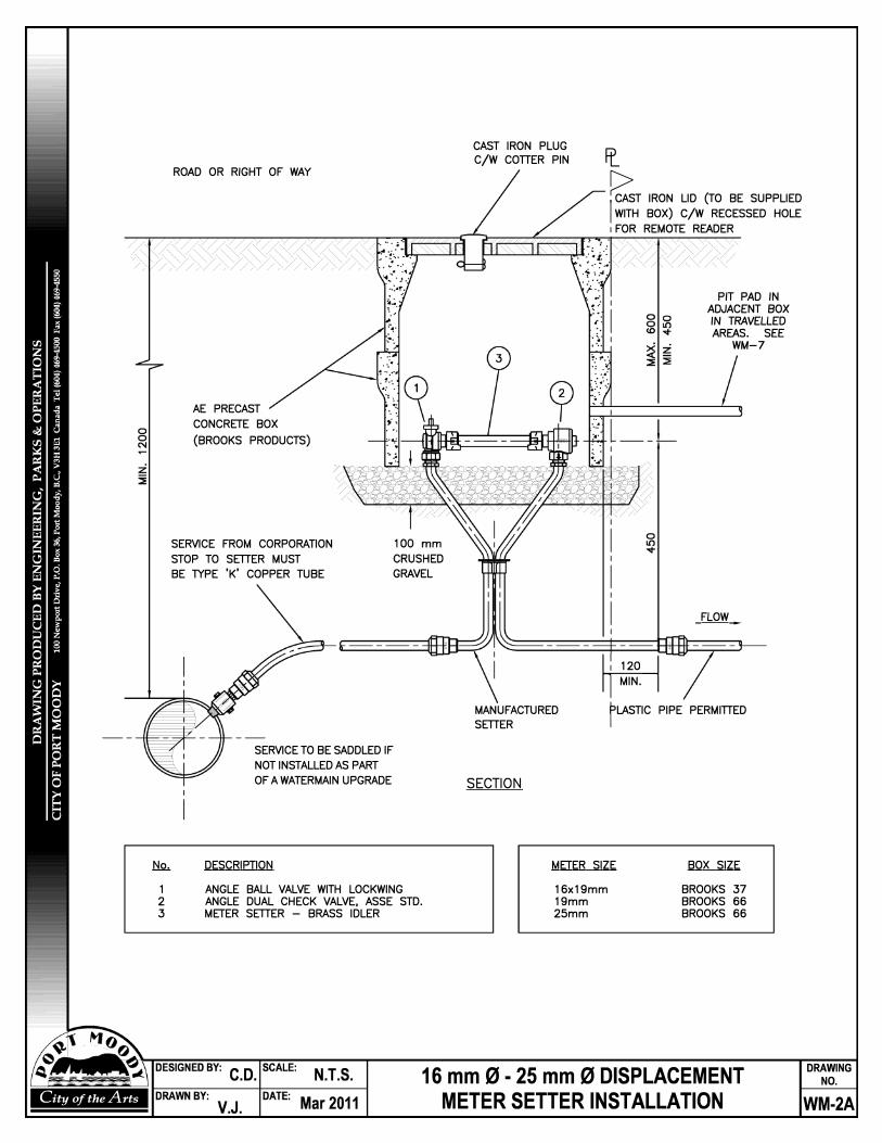
0 0 C'I
City of the Arts
N2..
1 2
3
ROAD OR RIGHT OF WAY
AE PRECAST CONCRETE BOX (BROOKS PRODUCTS)
SERVICE FROM CORPORATION STOP TO SETTER MUST
/
CAST IRON PLUG Ci> C/W COTTER PIN I L
� IRON LID (TO BE SUPPLIED I WITH BOX) C/W RECESSED HOLE 1FOR REMOTE READER
0 Ill
PIT PAD IN ADJACENT BOX IN TRAVELLED AREAS. SEE
WM-7
BE TYPE 'K' COPPER TUBE GRAVEL
DESCRIPTION
ANGLE BALL VALVE WITH LOCKWING ANGLE DUAL CHECK VALVE, ASSE STD. METER SETTER - BRASS IDLER
FLOW
� 11 MIN. I
MANUFACTURED SETTER FLASTIC PIPE PERMITTED
SECTION
METER SIZE
16x19mm
19mm
25mm
BOX SIZE
BROOKS 37 BROOKS 66
BROOKS 66
16 mm 0 - 25 mm 0 DISPLACEMENT
METER SETTER INSTALLATION
DRAWING NO.
WM-2A
SERVICE TO BE SADDLED IF NOT INSTALLED AS PART OF A WATERMAIN UPGRADE