Embed Size (px)
Citation preview
Cisco Systems This document is exclusive property of Cisco Systems, Inc. Permission is granted to print and copy this document for non-commercial distribution and exclusive use by instructors in the CCNA 3: Switching Basics and Intermediate Routing course as part of an official Cisco Networking Academy
Cisco Ststems
Lab 1.1.4 Calculating VLSM Subnets

60 hosts 12 hosts 12 hosts
Objective
Use variable-length subnet mask (VLSM) to support more efficient use of the assigned IP addresses and to reduce the amount of routing information at the top level.
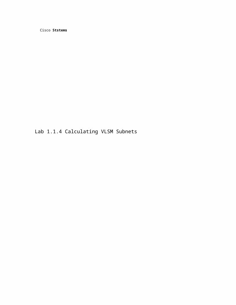
Background/Preparation A class C address of 192.168.10.0/24 has been allocated.
Perth, Sydney, and Singapore have a WAN connection to Kuala Lumpur.
• Perth requires 60 hosts.
• Kuala Lumpur requires 28 hosts.
• Sydney and Singapore each require 12 hosts.
To calculate VLSM subnets and the respective hosts allocate the largest requirements first from the address range. Requirements levels should be listed from the largest to the smallest.
In this example Perth requires 60 hosts. Use 6 bits since 2 6 -2 = 62 usable host addresses. Thus 2 bits will be used from the 4 th octet to represent the extended-network-prefix of/26 and the remaining 6 bits will be used for host addresses.
1 -5 CCNA3: Switching Basics and Intermediate Routing v 3.1 -Lab 1.1.4 Copyright © 2003, Cisco Systems, Inc.
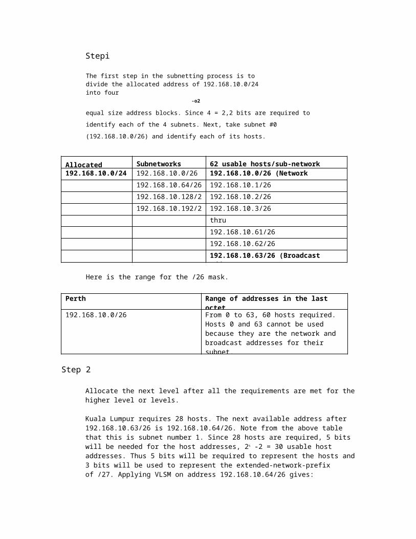
Stepi
The first step in the subnetting process is to divide the allocated address of 192.168.10.0/24 into four
-o2
equal size address blocks. Since 4 = 2,2 bits are required to identify each of the 4 subnets.
Next, take subnet #0 (192.168.10.0/26) and identify each of its hosts.
Allocated Address Subnetworks 62 usable hosts/sub-network (subnet #0) 192.168.10.0/24 192.168.10.0/26 192.168.10.0/26 (Network Address)
192.168.10.64/26 192.168.10.1/26
192.168.10.128/26 192.168.10.2/26
192.168.10.192/26 192.168.10.3/26
thru
192.168.10.61/26
192.168.10.62/26
192.168.10.63/26 (Broadcast Address)
Here is the range for the /26 mask.
Perth Range of addresses in the last octet
192.168.10.0/26 From 0 to 63, 60 hosts required. Hosts 0 and 63 cannot be used because they are the network and broadcast addresses for their subnet.
Step 2
Allocate the next level after all the requirements are met for the higher level or levels.
Kuala Lumpur requires 28 hosts. The next available address after 192.168.10.63/26 is 192.168.10.64/26. Note from the above table that this is subnet number 1. Since 28 hosts are required, 5 bits will be needed for the host addresses, 25 -2 = 30 usable host addresses. Thus 5 bits will be required to represent the hosts and 3 bits will be used to represent the extended-network-prefix of /27. Applying VLSM on address 192.168.10.64/26 gives:
Sub-network #1 Sub-sub-networks 30 usable hosts
192.168.10.64/27 (Network Address)
192.168.10.64/26 192.168.10.64/27 192.168.10.65/27
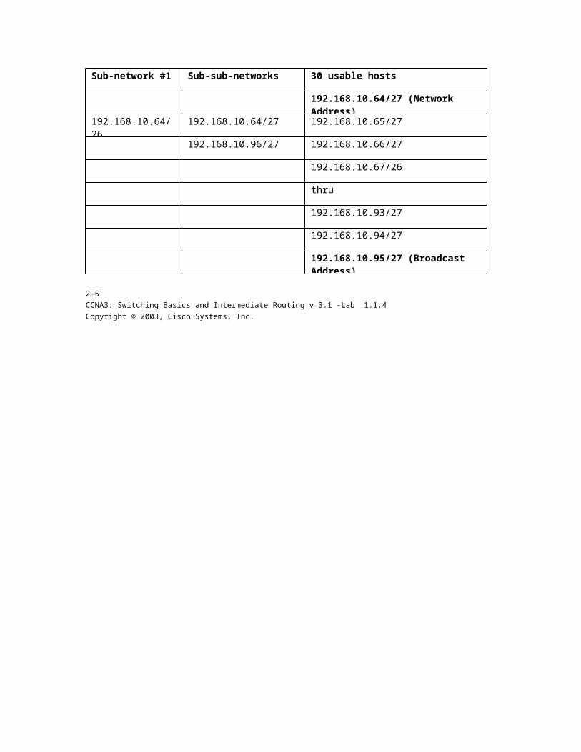
192.168.10.96/27 192.168.10.66/27
192.168.10.67/26
thru
192.168.10.93/27
192.168.10.94/27
192.168.10.95/27 (Broadcast Address)
2-5 CCNA3: Switching Basics and Intermediate Routing v 3.1 -Lab 1.1.4 Copyright © 2003, Cisco Systems, Inc.

Here is the range for the 121 mask.
Kuala Lumpur
Range of addresses in the last octet
192.168.10.64/27 From 64 to 95, 28 hosts required. Hosts 64 and 95 cannot be used because they are the network and broadcast addresses for their subnet. Thirty usable addresses are available in this range for the hosts.
Step 3
Now Sydney and Singapore require 12 hosts each. The next available address starts from 192.168.10.96/27. Note from Table 2 that this is the next subnet available. Since 12 hosts are required, 4 bits will be needed for the host addresses, 24 = 16, 16 -2 = 14 usable addresses. Thus 4 bits are required to represent the hosts and 4 bits for the extended-network-prefix of/28. Applying VLSM on address 192.168.10.96/27 gives:
Subnetwork Sub-sub-networks 14 usable hosts
192.168.10.96/27 192.168.10.96/28 192.168.10.96/28 (Network Address)
192.168.10.112/28 192.168.10.97/28
192.168.10.98/28
192.168.10.99/28
thru
192.168.10.109/28
192.168.10.110/28
192.168.10.111/28 (Broadcast Address)
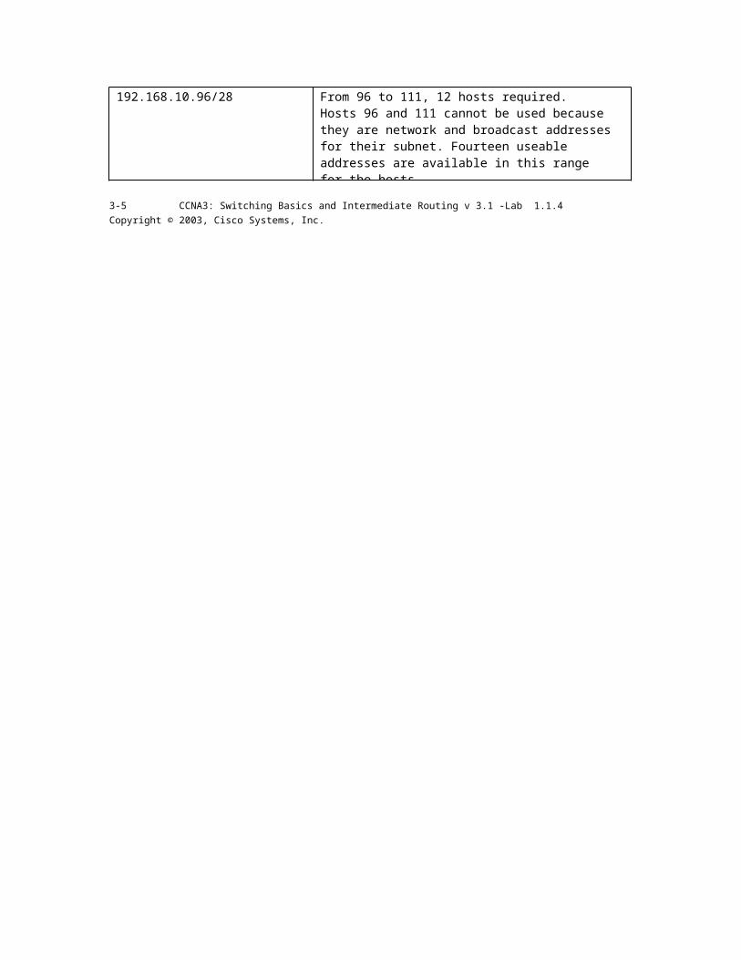
Here is the range for the /28 mask.
Sydney Range of addresses in the last octet
192.168.10.96/28 From 96 to 111, 12 hosts required. Hosts 96 and 111 cannot be used because they are network and broadcast addresses for their subnet. Fourteen useable addresses are available in this range for the hosts.
3-5 CCNA3: Switching Basics and Intermediate Routing v 3.1 -Lab 1.1.4 Copyright © 2003, Cisco Systems, Inc.

Step 4
Since Singapore also requires 12 hosts, the next set of host addresses can be derived from the next available subnet (192.168.10.112/28).
Sub
14 usable hosts
192.168.10.96/28 192.168.10.112/28 (Network Address)
192.168.10.112/28 192.168.10.113/28
192.168.10.128/28 192.168.10.114/28
192.168.10.224/28 192.168.10.115/28
Thru
192.168.10.240/28 192.168.10.125/28
192.168.10.126/28
192.168.10.127/28 (Broadcast Address)
Here is the range for the /28 mask.
Singapore Range of addresses in the last octet
192.168.10.112/28 From 112 to 127, 12 hosts required. Hosts 112 and 127 cannot be used because they are network and broadcast addresses for their subnet. Fourteen usable addresses are available in this range for the hosts.
4-5 CCNA3: Switching Basics and Intermediate Routing v 3.1 -Lab 1.1.4 Copyright © 2003, Cisco Systems, Inc.
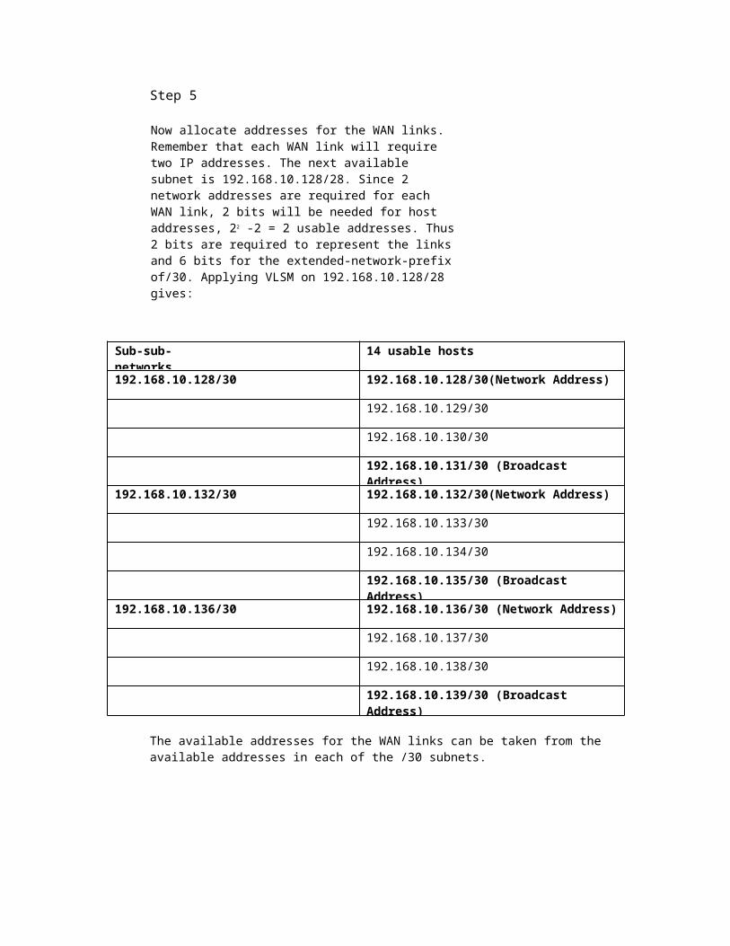
Step 5
Now allocate addresses for the WAN links. Remember that each WAN link will require two IP addresses. The next available subnet is 192.168.10.128/28. Since 2 network addresses are required for each WAN link, 2 bits will be needed for host addresses, 22 -2 = 2 usable addresses. Thus 2 bits are required to represent the links and 6 bits for the extended-network-prefix of/30. Applying VLSM on 192.168.10.128/28 gives:
Sub-sub-networks
14 usable hosts
192.168.10.128/30 192.168.10.128/30(Network Address)
192.168.10.129/30
192.168.10.130/30
192.168.10.131/30 (Broadcast Address)
192.168.10.132/30 192.168.10.132/30(Network Address)
192.168.10.133/30
192.168.10.134/30
192.168.10.135/30 (Broadcast Address)
192.168.10.136/30 192.168.10.136/30 (Network Address)
192.168.10.137/30
192.168.10.138/30
192.168.10.139/30 (Broadcast Address)
The available addresses for the WAN links can be taken from the available addresses in each of the /30 subnets.
5-5 CCNA3: Switching Basics and Intermediate Routing v 3.1 -Lab 1.1.4 Copyright © 2003, Cisco Systems, Inc.
Cisco Ststems
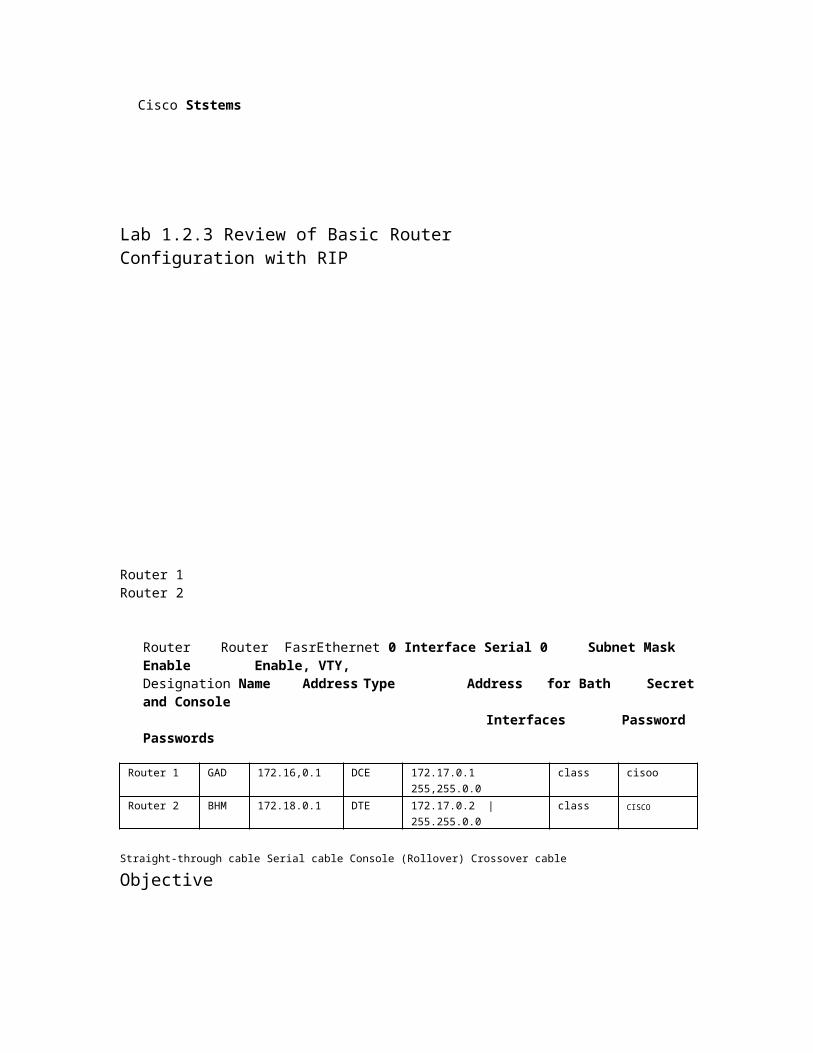
Lab 1.2.3 Review of Basic Router Configuration with RIP
Router 1 Router 2
Router Router FasrEthernet 0 Interface Serial 0 Subnet Mask Enable Enable, VTY, Designation Name Address Type Address for Bath Secret and Console
Interfaces Password Passwords
Router 1 GAD 172.16,0.1 DCE 172.17.0.1 255,255.0.0 class cisoo Router 2 BHM 172.18.0.1 DTE 172.17.0.2 | 255.255.0.0 class CISCO
Straight-through cable Serial cable Console (Rollover) Crossover cable
Objective
• Cable and configure workstations and routers
• Setup IP addressing scheme using Class B networks
• Configure Routing Information Protocol (RIP) on routers
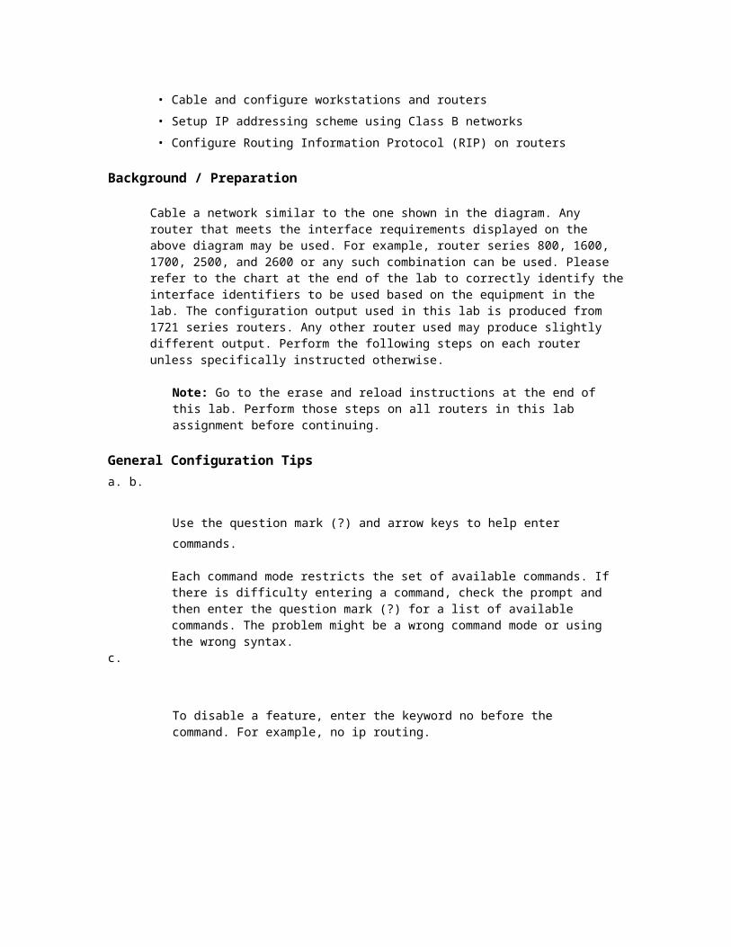
Background / Preparation
Cable a network similar to the one shown in the diagram. Any router that meets the interface requirements displayed on the above diagram may be used. For example, router series 800, 1600, 1700, 2500, and 2600 or any such combination can be used. Please refer to the chart at the end of the lab to correctly identify the interface identifiers to be used based on the equipment in the lab. The configuration output used in this lab is produced from 1721 series routers. Any other router used may produce slightly different output. Perform the following steps on each router unless specifically instructed otherwise.
Note: Go to the erase and reload instructions at the end of this lab. Perform those steps on all routers in this lab assignment before continuing.
General Configuration Tips a. b.
Use the question mark (?) and arrow keys to help enter commands.
Each command mode restricts the set of available commands. If there is difficulty entering a command, check the prompt and then enter the question mark (?) for a list of available commands. The problem might be a wrong command mode or using the wrong syntax.
c.
To disable a feature, enter the keyword no before the command. For example, no ip routing.
1-10 CCNA3: Switching Basics and Intermediate Routing v 3.1 -Lab 1.2.3 Copyright © 2003, Cisco Systems, Inc.

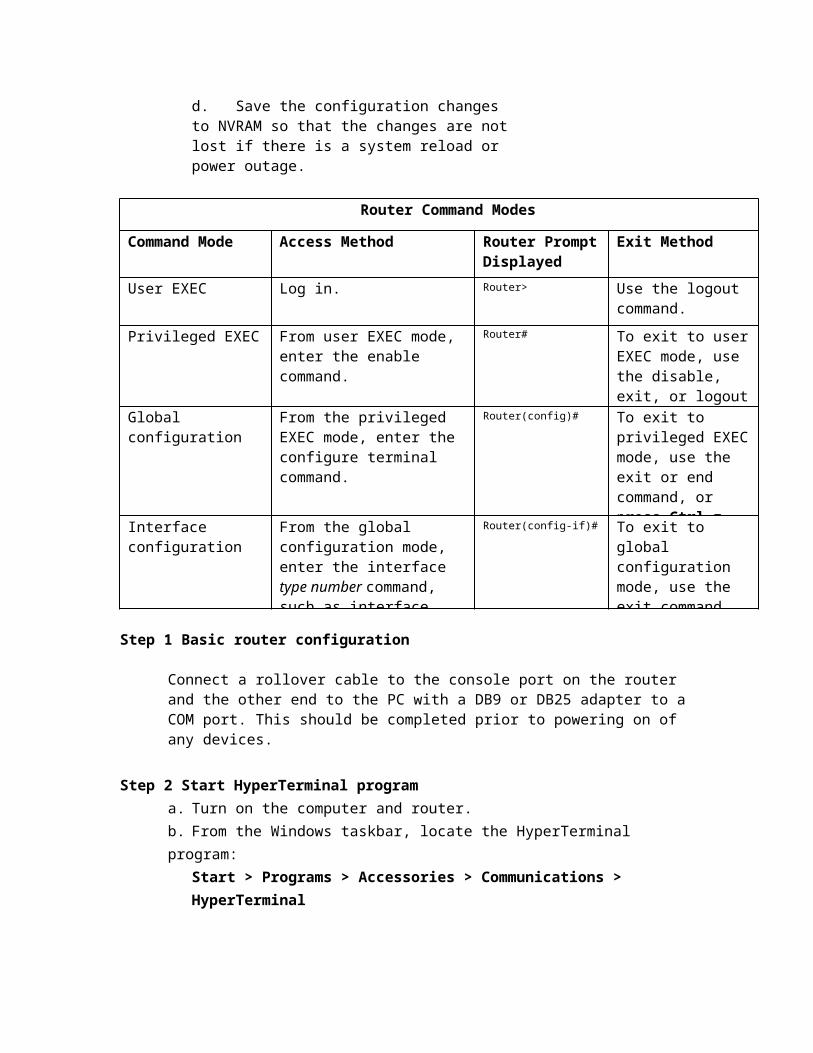
d. Save the configuration changes to NVRAM so that the changes are not lost if there is a system reload or power outage.
Router Command Modes
Command Mode Access Method Router Prompt Displayed
Exit Method
User EXEC Log in. Router> Use the logout command.
Privileged EXEC From user EXEC mode, enter the enable command.
Router# To exit to user EXEC mode, use the disable, exit, or logout command.
Global configuration From the privileged EXEC mode, enter the configure terminal command.
Router(config)# To exit to privileged EXEC mode, use the exit or end command, or press Ctrl-z.
Interface configuration
From the global configuration mode, enter the interface type number command, such as interface serial 0.
Router(config-if)# To exit to global configuration mode, use the exit command.
Step 1 Basic router configuration
Connect a rollover cable to the console port on the router and the other end to the PC with a DB9 or DB25 adapter to a COM port. This should be completed prior to powering on of any devices.
Step 2 Start HyperTerminal program a. Turn on the computer and router. b. From the Windows taskbar, locate the HyperTerminal program:
Start > Programs > Accessories > Communications > HyperTerminal
2-10 CCNA3: Switching Basics and Intermediate Routing v 3.1 -Lab 1.2.3
Copyright © 2003, Cisco Systems, Inc.
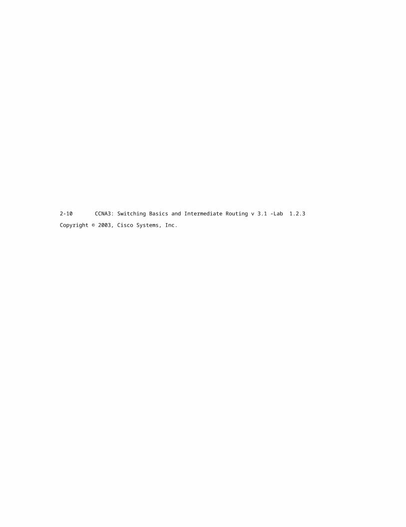
Step 3 Name the HyperTerminal Session


a. At the "Connection Description" popup, enter a name in the connection Name: field and select OK.
Connection Description
U New Connection
Enter a name and choose an icon for
the connection: Name:
Step 4 Specify the computer connecting interface

a. At the "Connect To" popup, use the drop down arrow in the Connect using: field to select COM1 and select OK.
Connect To
mark
Enter details for the phone number that you want to dial:
Country/regio
| U nited S tates of America (1)
dArea code: 1205
Phone number:
Connect using:
|
SHMBMMHMHHMI
d
OK |
Cancel I
Step 5 Specify the interface connection properties a. At the "COM1 Properties" popup, use the drop down arrows to select:
Bits per second: 9600 Data bits: 8 Parity: None Stop bits: 1 Flow control: None
b. Then select OK.
3-10 CCNA3: Switching Basics and Intermediate Routing v 3.1 -Lab 1.2.3 Copyright © 2003, Cisco Systems, Inc.

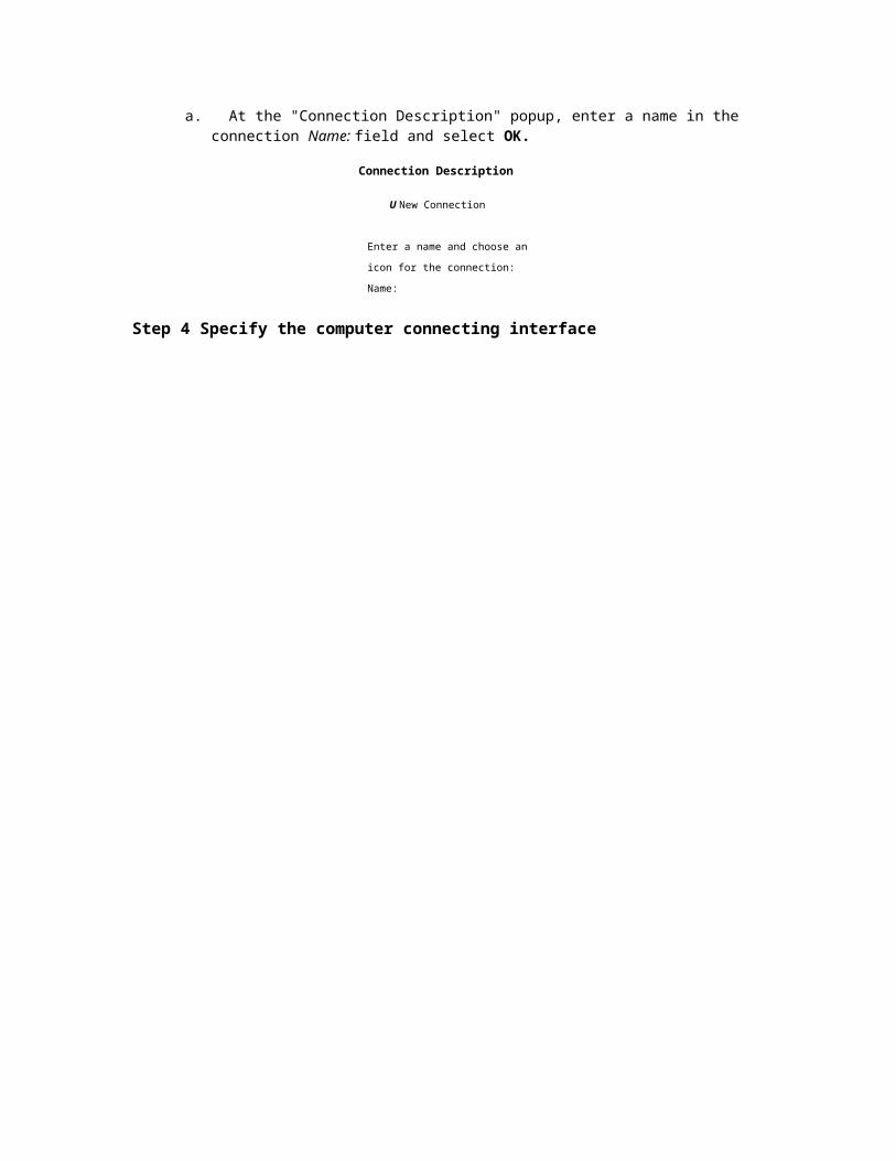
c. When the HyperTerminal session window comes up, turn on the router or if router is already on, press the Enter key. There should be a response from the router.
Cisco -HyperTerminal
-|p|x|
File Edit View Call Transfer Help
nnected 0:00:07 |vT100 19500 BNl
d
If the router responds, then the connection has been successfully completed.
Step 6 Closing the Session a. To end the console session from a HyperTerminal session, select:
File > Exit
b. When the HyperTerminal disconnect warning popup appears, select Yes.
4-10 CCNA3: Switching Basics and Intermediate Routing v 3.1 -Lab 1.2.3 Copyright © 2003, Cisco Systems, Inc.
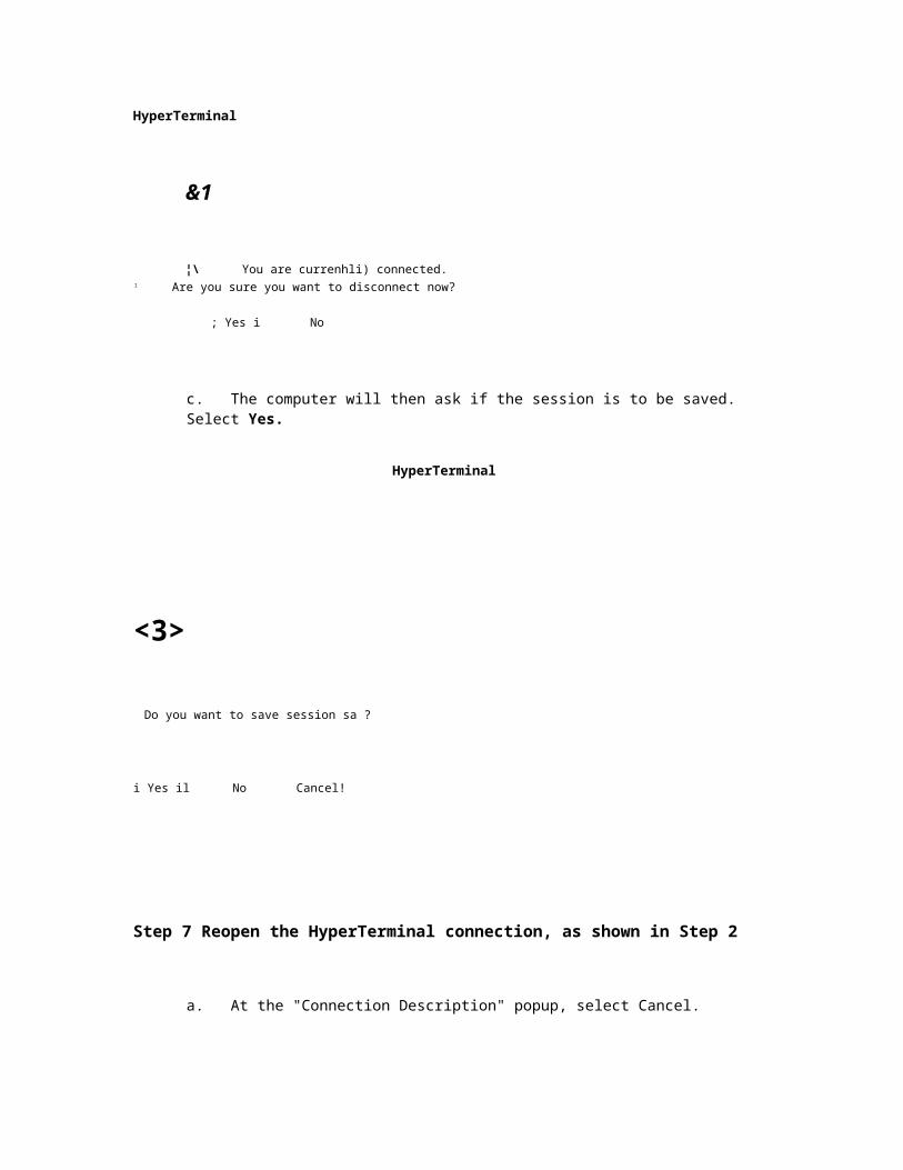
HyperTerminal
&1
¦\ You are currenhli) connected. 1 Are you sure you want to disconnect now?
; Yes i No
c. The computer will then ask if the session is to be saved. Select Yes.
HyperTerminal
<3>
Do you want to save session sa ?
i Yes il No Cancel!
Step 7 Reopen the HyperTerminal connection, as shown in Step 2
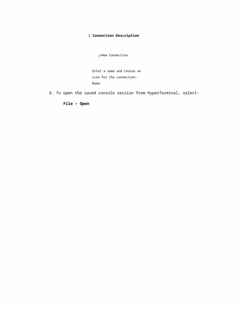
a. At the "Connection Description" popup, select Cancel.
I Connection Description
y New Connection
Enter a name and choose an icon for
the connection: Name:
b. To open the saved console session from HyperTerminal, select:
File > Open

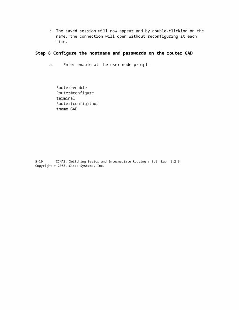
c. The saved session will now appear and by double-clicking on the name, the connection will open without reconfiguring it each time.
Step 8 Configure the hostname and passwords on the router GAD
a. Enter enable at the user mode prompt.
Router>enable Router#configure terminal Router(config)#hostname GAD
5-10 CCNA3: Switching Basics and Intermediate Routing v 3.1 -Lab 1.2.3 Copyright © 2003, Cisco Systems, Inc.
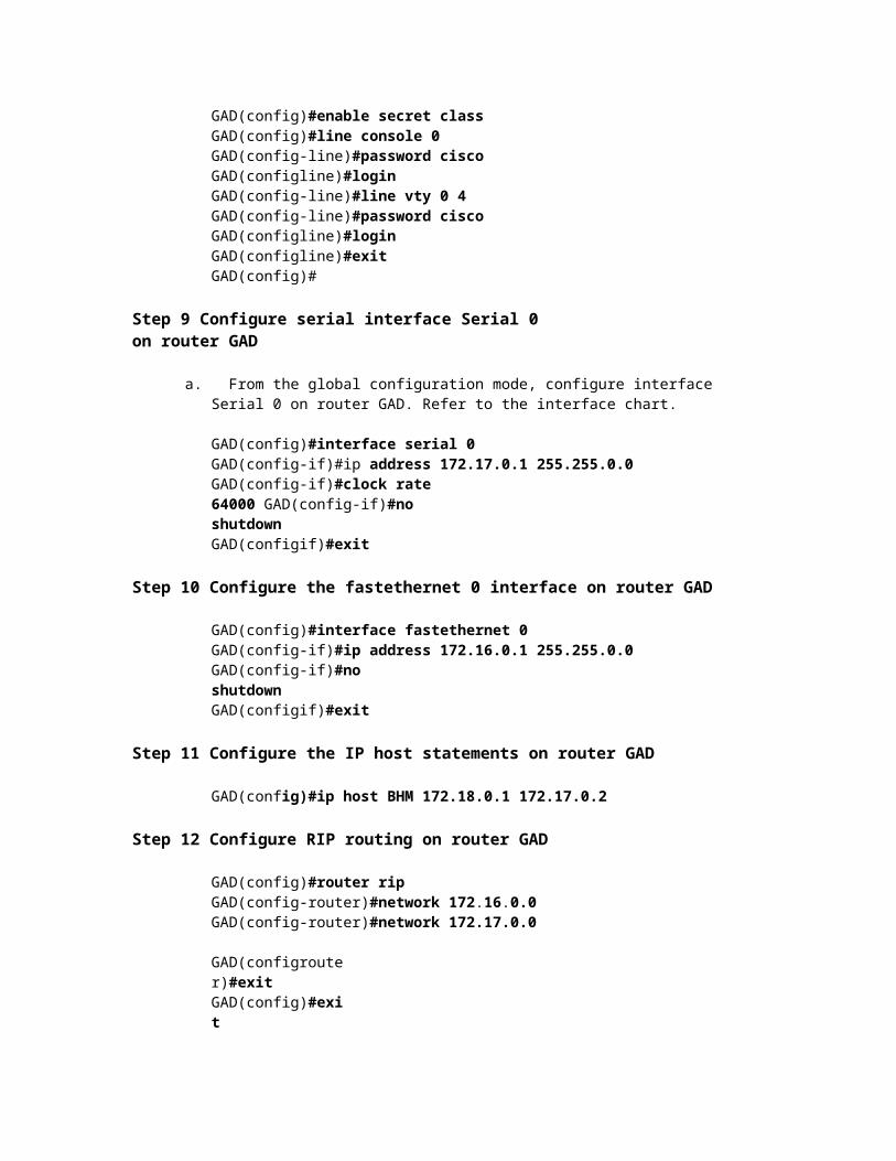
GAD(config)#enable secret class GAD(config)#line console 0 GAD(config-line)#password cisco GAD(configline)#login GAD(config-line)#line vty 0 4 GAD(config-line)#password cisco GAD(configline)#login GAD(configline)#exit GAD(config)#
Step 9 Configure serial interface Serial 0 on router GAD
a. From the global configuration mode, configure interface Serial 0 on router GAD. Refer to the interface chart.
GAD(config)#interface serial 0 GAD(config-if)#ip address 172.17.0.1 255.255.0.0 GAD(config-if)#clock rate 64000 GAD(config-if)#no shutdown GAD(configif)#exit
Step 10 Configure the fastethernet 0 interface on router GAD
GAD(config)#interface fastethernet 0 GAD(config-if)#ip address 172.16.0.1 255.255.0.0 GAD(config-if)#no shutdown GAD(configif)#exit
Step 11 Configure the IP host statements on router GAD
GAD(config)#ip host BHM 172.18.0.1 172.17.0.2
Step 12 Configure RIP routing on router GAD
GAD(config)#router rip GAD(config-router)#network 172.16.0.0 GAD(config-router)#network 172.17.0.0 GAD(configrouter)#exit GAD(config)#exit
Step 13 Save the GAD router configuration
GAD#copy running-config startup-config Destination filename [startup-config]?[Enter]
Step 14 Configure hostname and passwords on the router BHM
a. Enter enable at the user mode prompt.
6-10 CCNA3: Switching Basics and Intermediate Routing v3.1 -Lab 1.2.3 Copyright © 2003, Cisco Systems, Inc.

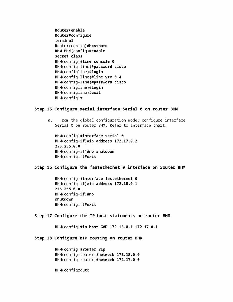
Router>enable Router#configure terminal Router(config)#hostname BHM BHM(config)#enable secret class BHM(config)#line console 0 BHM(config-line)#password cisco BHM(configline)#login BHM(config-line)#line vty 0 4 BHM(config-line)#password cisco BHM(configline)#login BHM(configline)#exit BHM(config)#
Step 15 Configure serial interface Serial 0 on router BHM
a. From the global configuration mode, configure interface Serial 0 on router BHM. Refer to interface chart.
BHM(config)#interface serial 0 BHM(config-if)#ip address 172.17.0.2 255.255.0.0 BHM(config-if)#no shutdown BHM(configif)#exit
Step 16 Configure the fastethernet 0 interface on router BHM
BHM(config)#interface fastethernet 0 BHM(config-if)#ip address 172.18.0.1 255.255.0.0 BHM(config-if)#no shutdown BHM(configif)#exit
Step 17 Configure the IP host statements on router BHM
BHM(config)#ip host GAD 172.16.0.1 172.17.0.1
Step 18 Configure RIP routing on router BHM
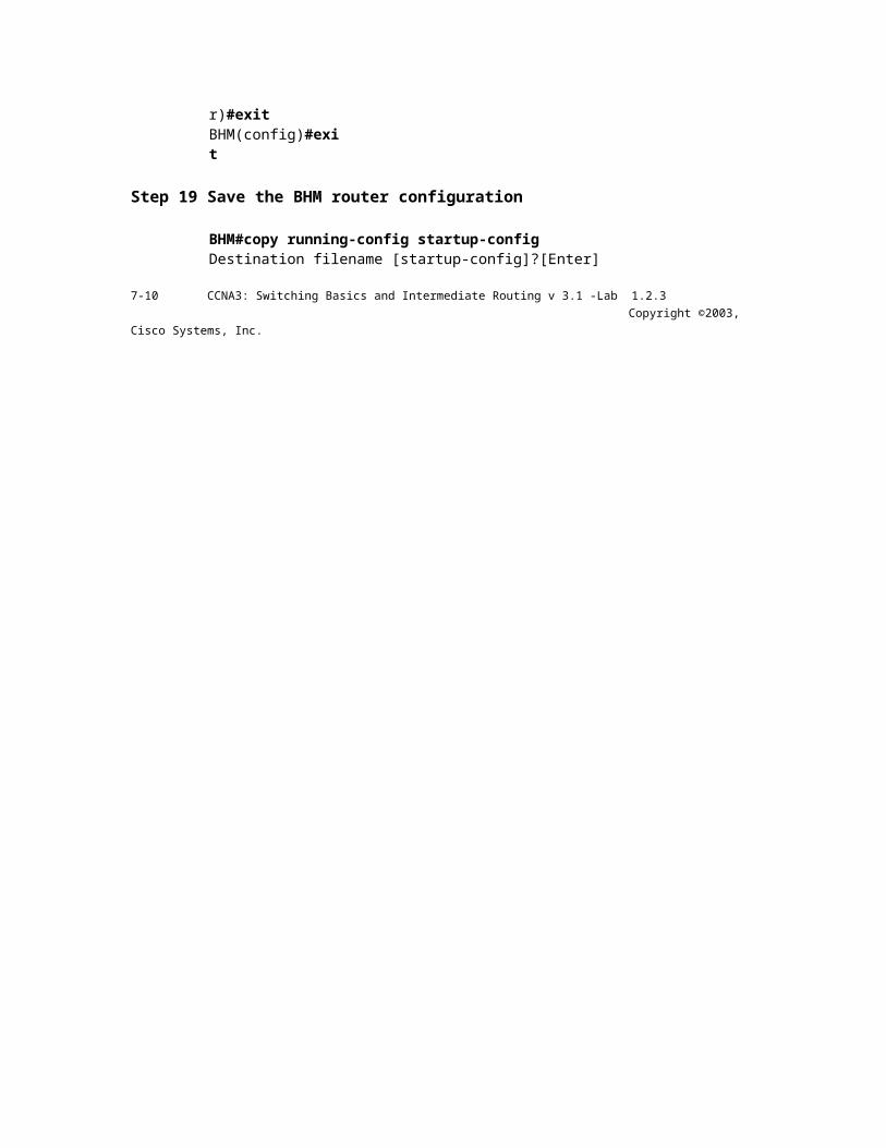
BHM(config)#router rip BHM(config-router)#network 172.18.0.0 BHM(config-router)#network 172.17.0.0 BHM(configrouter)#exit BHM(config)#exit
Step 19 Save the BHM router configuration
BHM#copy running-config startup-config Destination filename [startup-config]?[Enter]
7-10 CCNA3: Switching Basics and Intermediate Routing v 3.1 -Lab 1.2.3 Copyright ©2003, Cisco Systems, Inc.
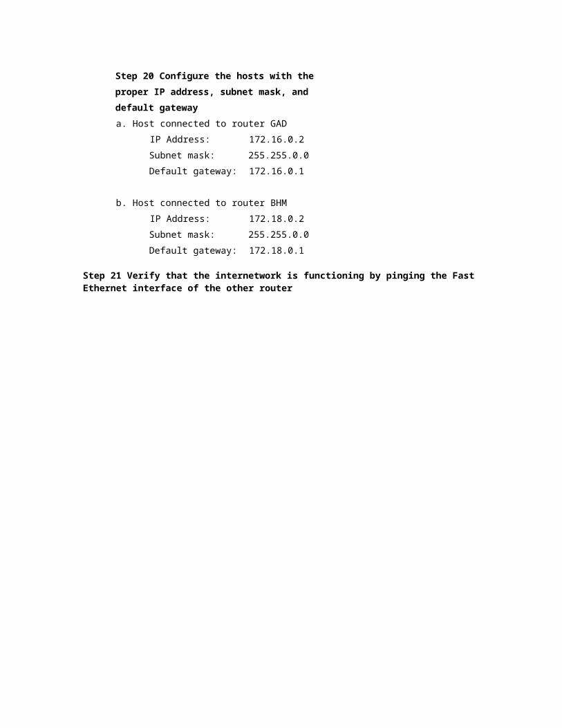
Step 20 Configure the hosts with the proper IP address, subnet mask, and default gateway a. Host connected to router GAD
IP Address: 172.16.0.2
Subnet mask: 255.255.0.0
Default gateway: 172.16.0.1
b. Host connected to router BHM
IP Address: 172.18.0.2
Subnet mask: 255.255.0.0
Default gateway: 172.18.0.1
Step 21 Verify that the internetwork is functioning by pinging the Fast Ethernet interface of the other router

a. From the host attached to GAD, ping the BHM router Fast Ethernet interface. Was the ping successful?


b. From the host attached to BHM, ping the GAD router Fast Ethernet interface. Was the ping successful?
c. If the answer is no for either question, troubleshoot the router configurations to find the error. Then do the pings again until the answer to both questions is yes. Then ping all interfaces in the network.
Step 22 Show the routing tables for each router a. From the enable privileged EXEC mode:
Examine the routing table entries, using the show ip route command on each router.
b. What are the entries in the GAD routing table?
c. What are the entries in the BHM routing table?
Once the previous steps are completed, logoff by typing exit, and turn the router off. Then remove and store the cables and adapter.
8-10 CCNA3: Switching Basics and Intermediate Routing v 3.1 -Lab 1.2.3 Copyright ©2003, Cisco Systems, Inc.
Erasing and reloading the router Enter into the privileged EXEC mode by typing enable.
Router>enable
If prompted for a password, enter class. If that does not work, ask the instructor for assistance. At the privileged EXEC mode, enter the command erase startup-config.
Router#erase startup-config The responding line prompt will be:
Erasing the nvram filesystem will remove all files! Continue? [confirm]
Press Enter to confirm. The response should be:
Erase of nvram: complete Now at the privileged EXEC mode, enter the command reload.
Router#reload The responding line prompt will be:
System configuration has been modified. Save? [yes/no]: Type n and then press Enter. The responding line prompt will be:
Proceed with reload?
[confirm] Press Enter to confirm. In the
first line of the response will be:
Reload requested by console. After
the router has reloaded the line prompt will
be:
Would you like to enter the initial configuration dialog? [yes/no]: Type
n and then press Enter. The responding line prompt will be:
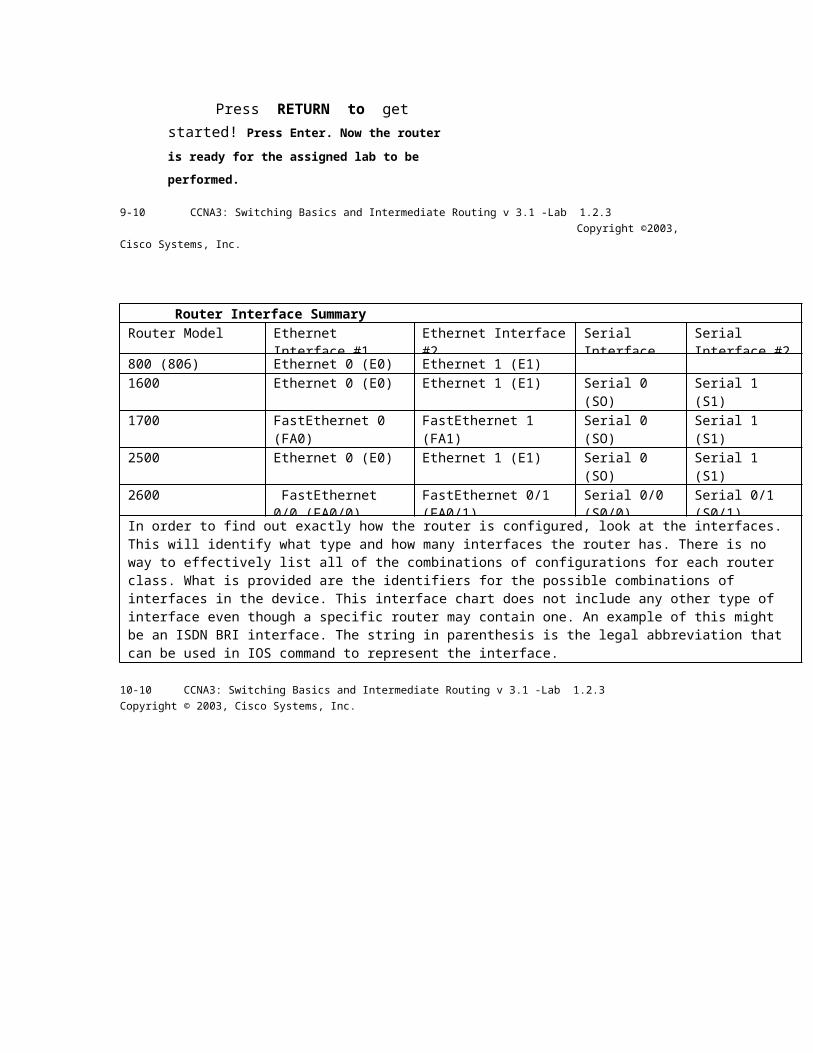
Press RETURN to get started!
Press Enter. Now the router is ready for the
assigned lab to be performed.
9-10 CCNA3: Switching Basics and Intermediate Routing v 3.1 -Lab 1.2.3 Copyright ©2003, Cisco Systems, Inc.
Router Interface Summary Router Model Ethernet Interface #1 Ethernet Interface #2 Serial Interface
#1 Serial Interface #2
800 (806) Ethernet 0 (E0) Ethernet 1 (E1) 1600 Ethernet 0 (E0) Ethernet 1 (E1) Serial 0 (SO) Serial 1 (S1) 1700 FastEthernet 0 (FA0) FastEthernet 1 (FA1) Serial 0 (SO) Serial 1 (S1) 2500 Ethernet 0 (E0) Ethernet 1 (E1) Serial 0 (SO) Serial 1 (S1) 2600 FastEthernet 0/0
(FA0/0) FastEthernet 0/1 (FA0/1)
Serial 0/0 (S0/0)
Serial 0/1 (S0/1)
In order to find out exactly how the router is configured, look at the interfaces. This will identify what type and how many interfaces the router has. There is no way to effectively list all of the combinations of configurations for each router class. What is provided are the identifiers for the possible combinations of interfaces in the device. This interface chart does not include any other type of interface even though a specific router may contain one. An example of this might be an ISDN BRI interface. The string in parenthesis is the legal abbreviation that can be used in IOS command to represent the interface.
10-10 CCNA3: Switching Basics and Intermediate Routing v 3.1 -Lab 1.2.3 Copyright © 2003, Cisco Systems, Inc.
Cisco Systems
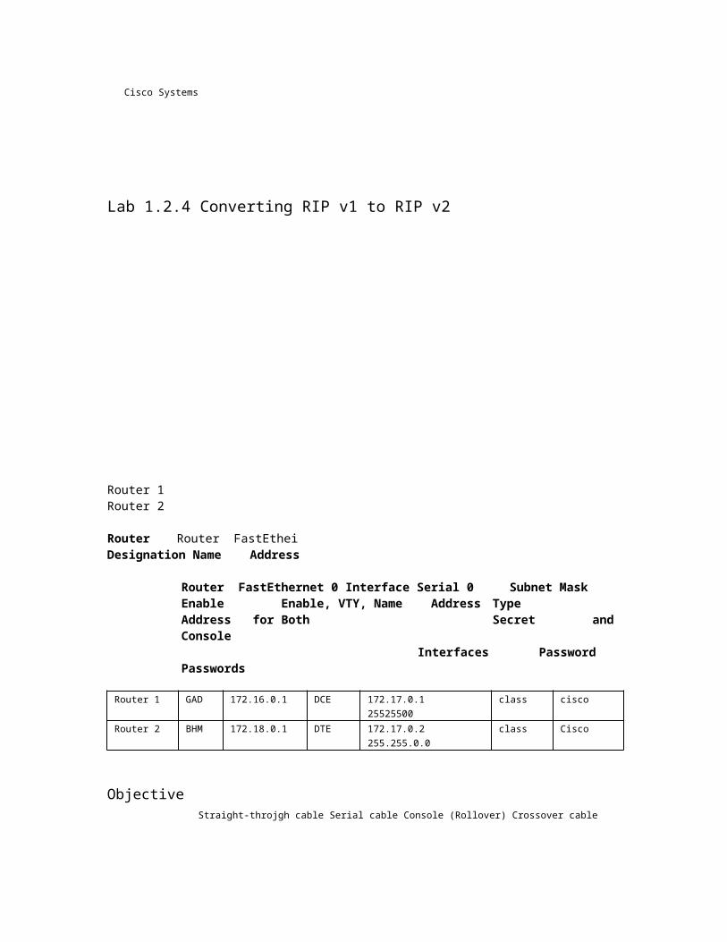
Lab 1.2.4 Converting RIP v1 to RIP v2
Router 1 Router 2
Router Router FastEthei Designation Name Address
Router FastEthernet 0 Interface Serial 0 Subnet Mask Enable Enable, VTY, Name Address Type Address for Both Secret and Console
Interfaces Password Passwords
Router 1 GAD 172.16.0.1 DCE 172.17.0.1 25525500 class cisco Router 2 BHM 172.18.0.1 DTE 172.17.0.2 255.255.0.0 class Cisco
Objective Straight-throjgh cable Serial cable Console (Rollover) Crossover cable
Configure RIP v1 on routers. Convert to RIP v2 on routers.
Background/Preparation
Cable a network similar to the shown in the diagram. Any router that meets the interface requirements displayed on the above diagram may be used. For example, router series 800, 1600, 1700, 2500 and 2600 or any such combination can be used. Please refer to the chart at the end of the lab to correctly identify the interface identifiers to be used based on the equipment in the lab. The configuration output used in this lab is produced from 1721 series routers. Any other router used may produce slightly different output. Perform the following steps on each router unless specifically instructed otherwise.
Start a HyperTerminal session as performed in the Establishing a HyperTerminal session lab.
Note: Go to the erase and reload instructions at the end of this lab. Perform those steps on all routers in this lab assignment before continuing.
Step 1 Configure the routers
On the routers, configure the hostnames as well as the console, virtual terminal, and enable passwords. Next configure the serial IP address and clock rate and the Fast Ethernet IP address interfaces. Finally configure IP host names. If there are problems performing the basic configuration, refer to the "Review of Basic Router Configuration with RIP" lab. Optional interface descriptions and message of the day banners may also be configured. Be sure to save the configurations just created.
Step 2 Configure the routing protocol on the GAD router
Go to the proper command mode and configure RIP routing on the GAD router according to the chart.
1 -4 CCNA 3: Switching Basics and Intermediate Routing v 3.1 -Lab 1.2.4 Copyright © 2003, Cisco Systems, Inc.
Step 3 Save the GAD router configuration
Any time that changes are correctly made to the running configuration, they should be saved to the startup configuration. Otherwise, if the router is reloaded or power cycled, the changes that are not saved in the startup configuration will be lost.
Step 4 Configure the routing protocol on the BHM router
Go to the proper command mode and configure RIP routing on the BHM router according to the chart.
Step 5 Save the BHM router configuration
Step 6 Configure the hosts with the proper IP address, subnet mask, and default gateway
Step 7 Verify that the internetwork is functioning by pinging the FastEthernet interface of the other router

a. From the host attached to GAD, ping the other host attached to the BHM router. Was the ping successful?


b. From the host attached to BHM, ping the other host attached to the GAD router. Was the ping successful?


c. If the answer is no for either question, troubleshootthe router configurations to find the error. Then do the pings again until the answer to both questions is yes.
Step 8 Enable RIP version 2 routing
a. Enable version 2 of the RIP routing protocol on both of the routers GAD and BHM.
GAD(config)#router rip GAD(config-router)#version 2 GAD(configrouter)#exit GAD(config)#exit
BHM(config)#router rip BHM(config-router)#version 2 BHM(configrouter)#exit BHM(config)#exit
Step 9 Ping all of the interfaces on the network from each host
a. Were all of the interfaces still able to be pinged?
b. If not, troubleshoot the network and ping again.
Once the previous steps are completed, logoff by typing exit, and turn the router off. Then remove and store the cables and adapter.
2 -4 CCNA 3: Switching Basics and Intermediate Routing v 3.1 -Lab 1.2.4 Copyright © 2003, Cisco Systems, Inc.

Erasing and reloading the router Enter into the privileged EXEC mode by typing enable.
Router>enable
If prompted fora password, enter class. If that does not work, ask the instructor for
assistance. At the privileged EXEC mode, enter the command erase startup-config.
Router#erase startup-config
The responding line prompt will be:
Erasing the nvram filesystem will remove all files! Continue? [confirm]
Press Enter to confirm. The response should be:
Erase of nvram: complete
Now at the privileged EXEC mode, enter the command reload.
Router(config)#reload
The responding line prompt will be:
System configuration has been modified. Save? [yes/no]:
Type n and then press
Enter. The responding
line prompt will be:
Proceed with reload? [confirm]
Press Enter to confirm.
In the first line of the response will be:
Reload requested by console.
After the router has reloaded the line prompt will be:
Would you like to enter the initial configuration dialog?
[yes/no]:
Type n and then press
Enter. The responding
line prompt will be:
Press RETURN to get started!
Press Enter.
Now the router is ready for the assigned lab to be performed.
3 -4 CCNA 3: Switching Basics and Intermediate Routing v 3.1 -Lab 1.2.4 Copyright © 2003, Cisco Systems, Inc.
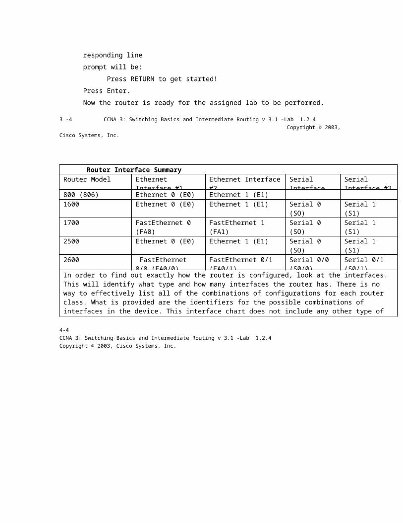
Router Interface Summary Router Model Ethernet Interface #1 Ethernet Interface #2 Serial Interface
#1 Serial Interface #2
800 (806) Ethernet 0 (E0) Ethernet 1 (E1) 1600 Ethernet 0 (E0) Ethernet 1 (E1) Serial 0 (SO) Serial 1 (S1) 1700 FastEthernet 0 (FA0) FastEthernet 1 (FA1) Serial 0 (SO) Serial 1 (S1) 2500 Ethernet 0 (E0) Ethernet 1 (E1) Serial 0 (SO) Serial 1 (S1) 2600 FastEthernet 0/0
(FA0/0) FastEthernet 0/1 (FA0/1)
Serial 0/0 (S0/0)
Serial 0/1 (S0/1)
In order to find out exactly how the router is configured, look at the interfaces. This will identify what type and how many interfaces the router has. There is no way to effectively list all of the combinations of configurations for each router class. What is provided are the identifiers for the possible combinations of interfaces in the device. This interface chart does not include any other type of interface even though a specific router may contain one. An example of this might be an ISDN BRI interface. The string in parenthesis is the legal abbreviation that can be used in IOS command to represent the interface.
4-4 CCNA 3: Switching Basics and Intermediate Routing v 3.1 -Lab 1.2.4 Copyright © 2003, Cisco Systems, Inc.

Cisco Systems
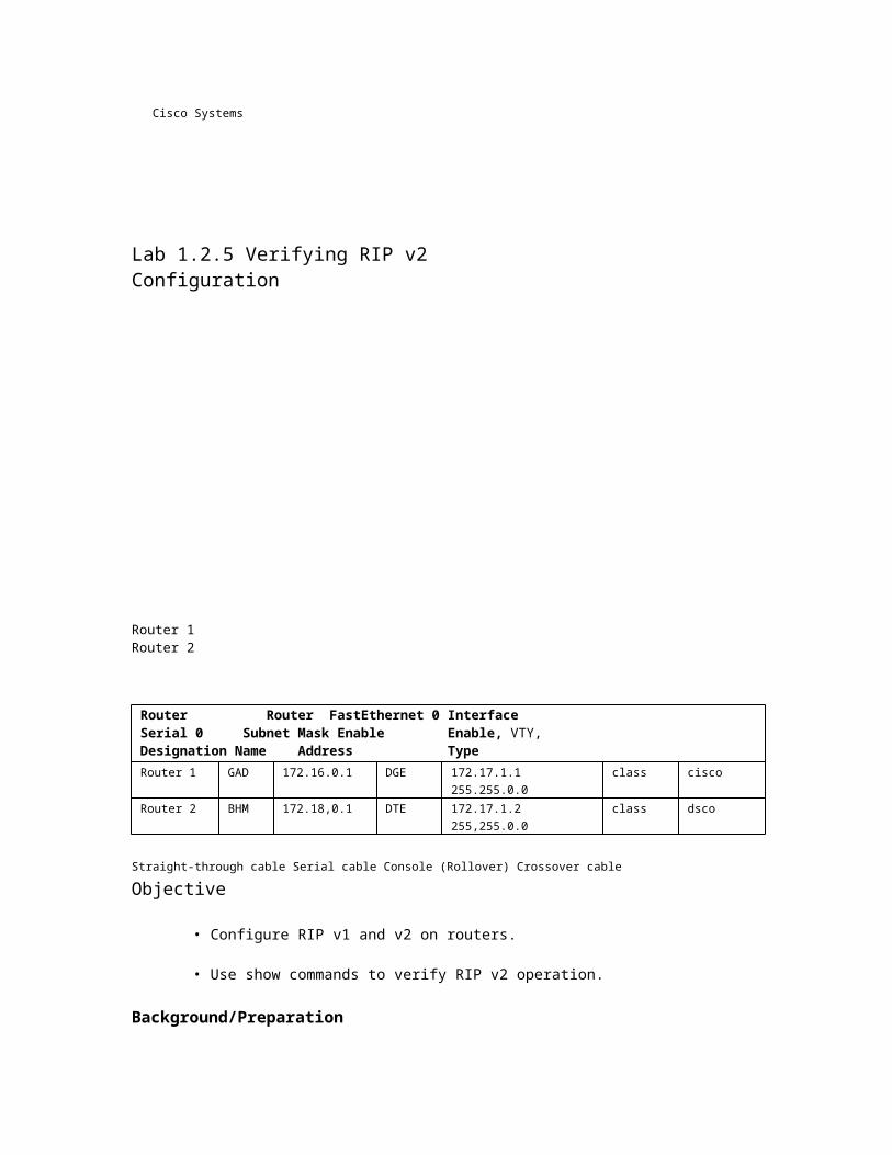
Lab 1.2.5 Verifying RIP v2 Configuration
Router 1 Router 2
Router Router FastEthernet 0 Interface Serial 0 Subnet Mask Enable Enable, VTY, Designation Name Address Type Address for Both Secret and Console Interfaces Password Passwords Router 1 GAD 172.16.0.1 DGE 172.17.1.1 255.255.0.0 class cisco Router 2 BHM 172.18,0.1 DTE 172.17.1.2 255,255.0.0 class dsco
Straight-through cable Serial cable Console (Rollover) Crossover cable
Objective
• Configure RIP v1 and v2 on routers.
• Use show commands to verify RIP v2 operation.
Background/Preparation
Cable a network similar to the one shown in the diagram. Any router that meets the interface requirements displayed on the above diagram may be used. For example, router series 800, 1600, 1700, 2500, and 2600 or any such combination can be used. Please refer to the chart at the end of the lab to correctly identify the interface identifiers to be used based on the equipment in the lab. The configuration output used in this lab is produced from 1721 series routers. Any other router used may produce slightly different
output. Perform the following steps on each router unless specifically instructed otherwise.
Start a HyperTerminal session as performed in the Establishing a HyperTerminal session lab.
Note: Go to the erase and reload instructions at the end of this lab. Perform those steps on all routers in this lab assignment before continuing.
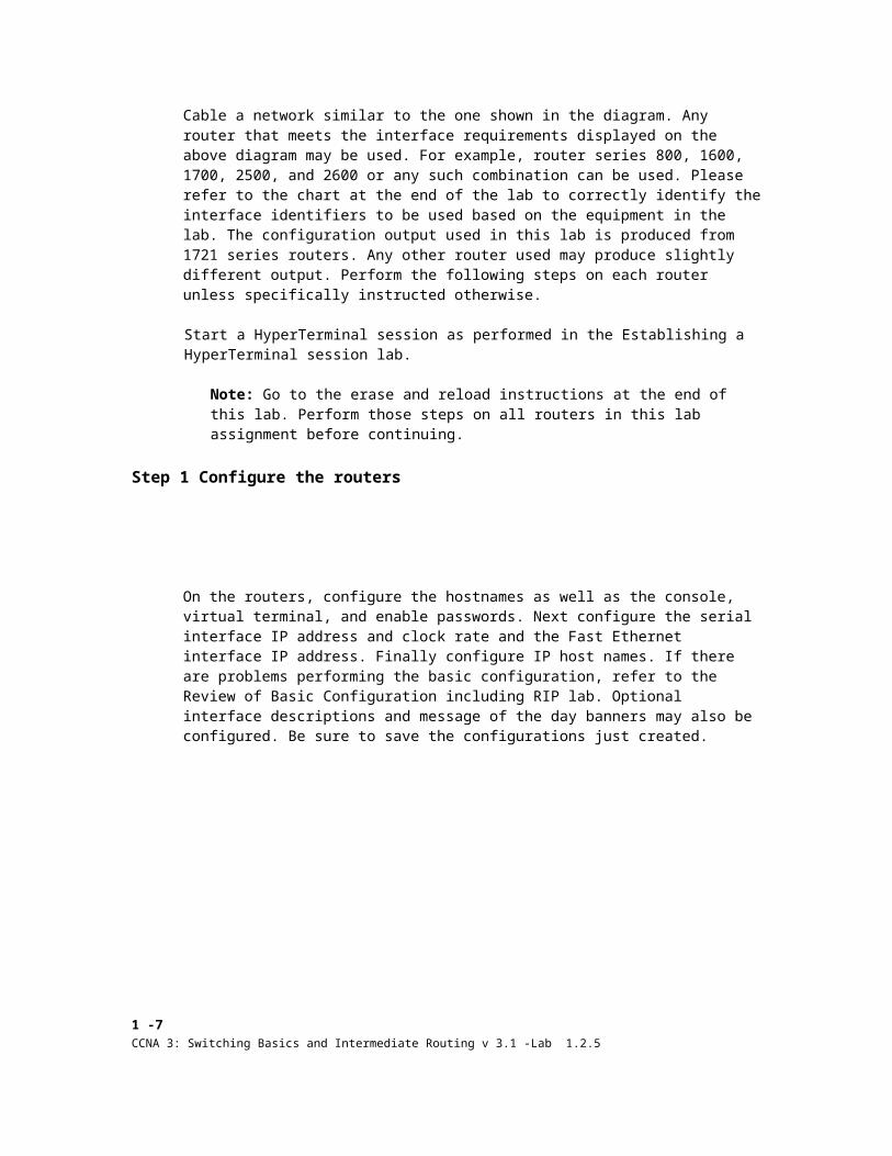
Step 1 Configure the routers
On the routers, configure the hostnames as well as the console, virtual terminal, and enable passwords. Next configure the serial interface IP address and clock rate and the Fast Ethernet interface IP address. Finally configure IP host names. If there are problems performing the basic configuration, refer to the Review of Basic Configuration including RIP lab. Optional interface descriptions and message of the day banners may also be configured. Be sure to save the configurations just created.
1 -7 CCNA 3: Switching Basics and Intermediate Routing v 3.1 -Lab 1.2.5 Copyright © 2003, Cisco Systems, Inc.
Step 2 Configure the routing protocol on the GAD router
Go to the correct command mode and configure RIP routing on the GAD router according to the chart.
Step 3 Save the GAD router configuration
Any time that changes are correctly made to the running configuration, they should be saved to the startup configuration. Otherwise, if the router is reloaded or power cycled, the changes that are not saved in the startup configuration will be lost.
Step 4 Configure the routing protocol on the BHM router
Go to the correct command mode and configure RIP routing on the BHM router according to the chart.
Step 5 Save the BHM router configuration
Step 6 Configure the hosts with the proper IP address, subnet mask, and default gateway
Step 7 Verify that the internetwork is functioning by pinging the FastEthernet interface of the other router

a. From the host attached to the GAD, ping the other host attached to the BHM router. Was the ping successful?

b. From the host attached to the BHM, ping the other host attached to the GAD router. Was the ping successful?


c. If the answer is no for either question, troubleshootthe router configurations to find the error. Then do the pings again until the answer to both questions is yes.
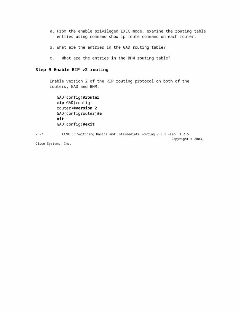
Step 8 Show the routing tables for each router


a. From the enable privileged EXEC mode, examine the routing table entries using command show ip route command on each router.
b. What are the entries in the GAD routing table?
c. What are the entries in the BHM routing table?
Step 9 Enable RIP v2 routing
Enable version 2 of the RIP routing protocol on both of the routers, GAD and BHM.
GAD(config)#router rip GAD(config-router)#version 2 GAD(configrouter)#exit GAD(config)#exit
2 -7 CCNA 3: Switching Basics and Intermediate Routing v 3.1 -Lab 1.2.5 Copyright © 2003, Cisco Systems, Inc.

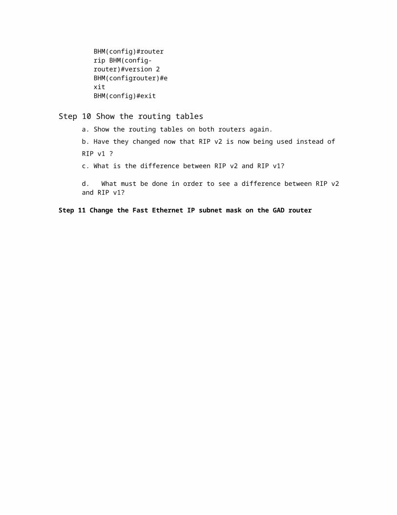
BHM(config)#router rip BHM(config-router)#version 2 BHM(configrouter)#exit BHM(config)#exit
Step 10 Show the routing tables a. Show the routing tables on both routers again.
b. Have they changed now that RIP v2 is now being used instead of RIP v1 ?
c. What is the difference between RIP v2 and RIP v1?
d. What must be done in order to see a difference between RIP v2 and RIP v1?
Step 11 Change the Fast Ethernet IP subnet mask on the GAD router

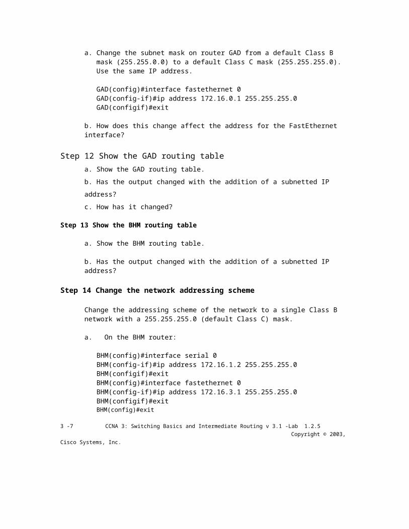
a. Change the subnet mask on router GAD from a default Class B mask (255.255.0.0) to a default Class C mask (255.255.255.0). Use the same IP address.
GAD(config)#interface fastethernet 0 GAD(config-if)#ip address 172.16.0.1 255.255.255.0 GAD(configif)#exit
b. How does this change affect the address for the FastEthernet interface?
Step 12 Show the GAD routing table a. Show the GAD routing table.
b. Has the output changed with the addition of a subnetted IP address?
c. How has it changed?
Step 13 Show the BHM routing table
a. Show the BHM routing table.
b. Has the output changed with the addition of a subnetted IP address?
Step 14 Change the network addressing scheme
Change the addressing scheme of the network to a single Class B network with a 255.255.255.0 (default Class C) mask.
a. On the BHM router:
BHM(config)#interface serial 0 BHM(config-if)#ip address 172.16.1.2 255.255.255.0 BHM(configif)#exit BHM(config)#interface fastethernet 0 BHM(config-if)#ip address 172.16.3.1 255.255.255.0 BHM(configif)#exit BHM(config)#exit
3 -7 CCNA 3: Switching Basics and Intermediate Routing v 3.1 -Lab 1.2.5 Copyright © 2003, Cisco Systems, Inc.
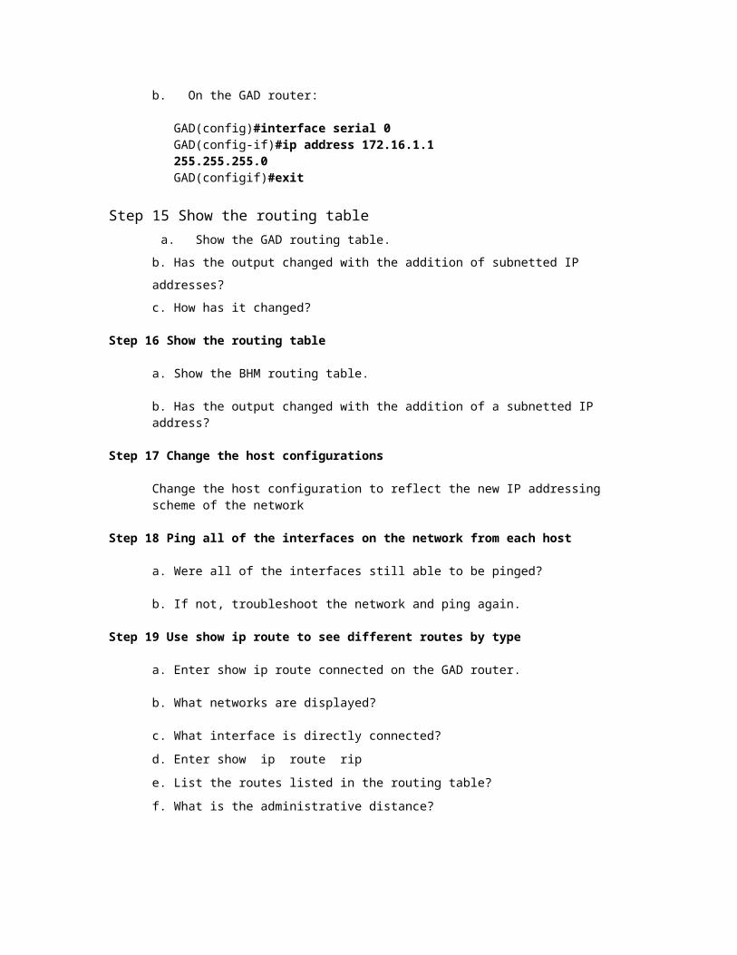
b. On the GAD router:
GAD(config)#interface serial 0 GAD(config-if)#ip address 172.16.1.1 255.255.255.0 GAD(configif)#exit
Step 15 Show the routing table a. Show the GAD routing table.
b. Has the output changed with the addition of subnetted IP addresses?
c. How has it changed?
Step 16 Show the routing table
a. Show the BHM routing table.
b. Has the output changed with the addition of a subnetted IP address?
Step 17 Change the host configurations
Change the host configuration to reflect the new IP addressing scheme of the network
Step 18 Ping all of the interfaces on the network from each host
a. Were all of the interfaces still able to be pinged?
b. If not, troubleshoot the network and ping again.
Step 19 Use show ip route to see different routes by type
a. Enter show ip route connected on the GAD router.
b. What networks are displayed?
c. What interface is directly connected?
d. Enter show ip route rip
e. List the routes listed in the routing table?
f. What is the administrative distance?
g. Enter show ip route connected on the BHM router,
h. What networks are displayed?
i. What interface is directly connected?
j. Enter show ip route rip
k. List the routes listed in the routing table?
Step 20 Use the show IP protocol command

a. Enter show ip protocol on the GAD router.
b. When will the routes be flushed?
c. What is the default distance listed for RIP?
4 -7 CCNA 3: Switching Basics and Intermediate Routing v 3.1 -Lab 1.2.5 Copyright © 2003, Cisco Systems, Inc.
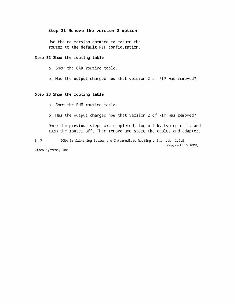
Step 21 Remove the version 2 option
Use the no version command to return the router to the default RIP configuration.
Step 22 Show the routing table
a. Show the GAD routing table.
b. Has the output changed now that version 2 of RIP was removed?
Step 23 Show the routing table
a. Show the BHM routing table.
b. Has the output changed now that version 2 of RIP was removed?
Once the previous steps are completed, log off by typing exit, and turn the router off. Then remove and store the cables and adapter.
5 -7 CCNA 3: Switching Basics and Intermediate Routing v 3.1 -Lab 1.2.5 Copyright © 2003, Cisco Systems, Inc.
Erasing and reloading the router Enter into the privileged EXEC mode by typing enable.
Router>enable
If prompted fora password, enter class. If that does not work, ask the instructor for
assistance. At the privileged EXEC mode, enter the command erase startup-config.
Router#erase startup-config
The responding line prompt will be:
Erasing the nvram filesystem will remove all files! Continue? [confirm]
Press Enter to confirm. The response should be:
Erase of nvram: complete
Now at the privileged EXEC mode, enter the command reload.
Router(config)#reload
The responding line prompt will be:
System configuration has been modified. Save? [yes/no]:
Type n and then press
Enter. The responding
line prompt will be:
Proceed with reload? [confirm]
Press Enter to confirm.
In the first line of the response will be:
Reload requested by console.
After the router has reloaded the line prompt will be:
Would you like to enter the initial configuration dialog?
[yes/no]:
Type n and then press
Enter. The responding
line prompt will be:
Press RETURN to get started!
Press Enter.

Now the router is ready for the assigned lab to be performed.
6 -7 CCNA 3: Switching Basics and Intermediate Routing v 3.1 -Lab 1.2.5 Copyright © 2003, Cisco Systems, Inc.
Router Interface Summary Router Model Ethernet Interface #1 Ethernet Interface #2 Serial Interface
#1 Serial Interface #2
800 (806) Ethernet 0 (E0) Ethernet 1 (E1) 1600 Ethernet 0 (E0) Ethernet 1 (E1) Serial 0 (SO) Serial 1 (S1) 1700 FastEthernet 0 (FA0) FastEthernet 1 (FA1) Serial 0 (SO) Serial 1 (S1) 2500 Ethernet 0 (E0) Ethernet 1 (E1) Serial 0 (SO) Serial 1 (S1) 2600 FastEthernet 0/0
(FA0/0) FastEthernet 0/1 (FA0/1)
Serial 0/0 (S0/0)
Serial 0/1 (S0/1)
In order to find out exactly how the router is configured, look at the interfaces. This will identify what type and how many interfaces the router has. There is no way to effectively list all of the combinations of configurations for each router class. What is provided are the identifiers for the possible combinations of interfaces in the device. This interface chart does not include any other type of interface even though a specific router may contain one. An example of this might be an ISDN BRI interface. The string in parenthesis is the legal abbreviation that can be used in IOS command to represent the interface.
7-7 CCNA 3: Switching Basics and Intermediate Routing v 3.1 -Lab 1.2.5 Copyright © 2003, Cisco Systems, Inc.
Cisco Ststems
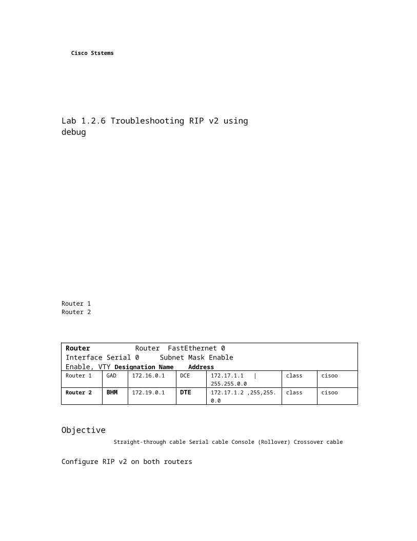
Lab 1.2.6 Troubleshooting RIP v2 using debug
Router 1 Router 2
Router Router FastEthernet 0 Interface Serial 0 Subnet Mask Enable Enable, VTY Designation Name Address Type Address for Both Secret and Console Interfaces Password Passwords Router 1 GAD 172.16.0.1 DCE 172.17.1.1 | 255.255.0.0 class cisoo Router 2 BHM 172.19.0.1 DTE 172.17.1.2 ,255,255.0.0 class cisoo
Objective Straight-through cable Serial cable Console (Rollover) Crossover cable
Configure RIP v2 on both routers
• Use debug commands to verify proper RIP operation and analyze data transmitted between routers.
Background/Preparation
Cable a network similar to the one shown in the diagram. Any router that meets the interface requirements displayed on the above diagram may be used. For example, router series 800, 1600, 1700, 2500, and 2600 or any such combination can be used. Please refer to the chart at the end of the lab to correctly identify the interface identifiers to be used based on the equipment in the lab. The configuration output used in this lab is produced from 1721 series routers. Any other router used may produce slightly different output. Perform the following steps on each router unless specifically instructed otherwise.
Start a HyperTerminal session as performed in the Establishing a HyperTerminal session lab.
Note: Go to the erase and reload instructions at the end of this lab. Perform those steps on all routers in this lab assignment before continuing.
Step 1 Configure the routers
On the routers, configure the hostnames as well as the console, virtual terminal, and enable passwords. Next configure the serial interface IP address and clock rate and the Fast Ethernet interface IP address. Finally configure IP host names. If there are problems performing the basic configuration, refer to the Review of Basic Configuration including RIP lab. Optional interface descriptions and message of the day banners may also be configured. Be sure to save the configurations just created.
1 -6 CCNA3: Switching Basics and Intermediate Routing v 3.1 -Lab 1.2.6 Copyright © 2003, Cisco Systems, Inc.

Step 2 Configure the routing protocol on the GAD router
Go to the proper command mode and configure RIP routing on the GAD router according to the chart.
Step 3 Save the GAD router configuration
Any time that changes are correctly made to the running configuration, they should be saved to the startup configuration. Otherwise if the router is reloaded or power cycled, the changes that are not in the startup configuration will be lost.
Step 4 Configure the routing protocol on the BHM router
Go to the proper command mode and configure RIP routing on the BHM router according to the chart.
Step 5 Save the BHM router configuration
Step 6 Configure the hosts with the proper IP address, subnet mask, and default gateway
Step 7 Verify that the internetwork is functioning by pinging the FastEthernet interface of the other router
a. From the host attached to the GAD, ping the other host attached to the BHM router. Was the ping successful?
b. From the host attached to the BHM, ping the other host attached to the GAD router. Was the ping successful?

c. If the answer is no for either question, troubleshoot the router configurations to find the error. Then do the pings again until the answer to both questions is yes.
Step 8 Show the debug IP options
a. At the privileged EXEC mode type debug ip ?.
b. Which routing protocols can use debug commands?
Step 9 Show the debug IP RIP options
a. At the privileged EXEC mode type debug ip rip ?.
b. How many options are available for debug ip rip ??
Step 10 Show the RIP routing updates
a. From the enable privileged EXEC mode, examine the routing table entries using command debug ip rip command on each router.
b. What are the three operations that take place listed in the rip debug statements?
c. Turn off debugging by typing either no debug ip riporundebug all.
Step 11 Enable RIP Version 2 Routing
Enable version 2 of the RIP routing protocol on the GAD router only.
2 -6 CCNA 3: Switching Basics and Intermediate Routing v 3.1 -Lab 1.2.6 Copyright © 2003, Cisco Systems, Inc.

Step 12 Start the debug function again on the
GAD router
a. Does a problem occur now that we have RIP v2 on the GAD router?
b. What is the problem?
Step 13 Clear the routing table


a. Instead of waiting for the routes to time out, type clear ip route *. Then type show ip route.
b. What has happened to the routing table?
c. Will it be updated to include RIP routes if the debug output says the update is ignored?
Step 14 Start the debug RIP function
a. Start the debug RIP function on the BHM router again by typing debug ip rip.
b. Does a problem occur now that RIP v2 is on the GAD router?
c. What is the problem?
Step 15 Clear the routing table
a. Instead of waiting for the routes to time out, type clear ip route *. Then type show ip route.
b. What has happened to the routing table?
c. Does a problem occur now that RIP v2 is on the GAD router?_
d. Turn off debugging by typing either no debug ip riporundebug all.
Step 16 Enable RIP version 2 routing
Enable version 2 of the RIP routing protocol on the BHM router.
Step 17 Use the debug function to see packet traffic on a router
a. Use the debug function to see packet traffic on the GAD router by typing debug ip packet at the privileged EXEC mode.
b. When an RIP update is sent how many source addresses are used?
c. Why are multiple source addresses used?
d. What is the source address used?
e. Why is this address used?
Step 18 Start the debug RIP database function on the BHM router

a. Start the RIP database debugging by typing debug ip rip database, then clear the routing table by typing clear ip route *.
b. Are the old routes in the table deleted?
c. Are new routes added back into the table?
d. What does the last entry in the debug output say?
e. Turn off debugging by typing either no debug ip riporundebug all.
3 -6 CCNA 3: Switching Basics and Intermediate Routing v 3.1 -Lab 1.2.6 Copyright © 2003, Cisco Systems, Inc.

Step 19 Use the debug events function to see routing updates

a. Use the debug function to see routing updates by typing debug ip rip events in privileged EXEC mode on the BHM router.
b. What interfaces are the routing updates sent on?
c. How many routes are in the routing updates being sent?
Once the previous steps are completed, log off by typing exit, and turn the router off. Then remove and store the cables and adapter.
4 -6 CCNA 3: Switching Basics and Intermediate Routing v 3.1 -Lab 1.2.6 Copyright © 2003, Cisco Systems, Inc.

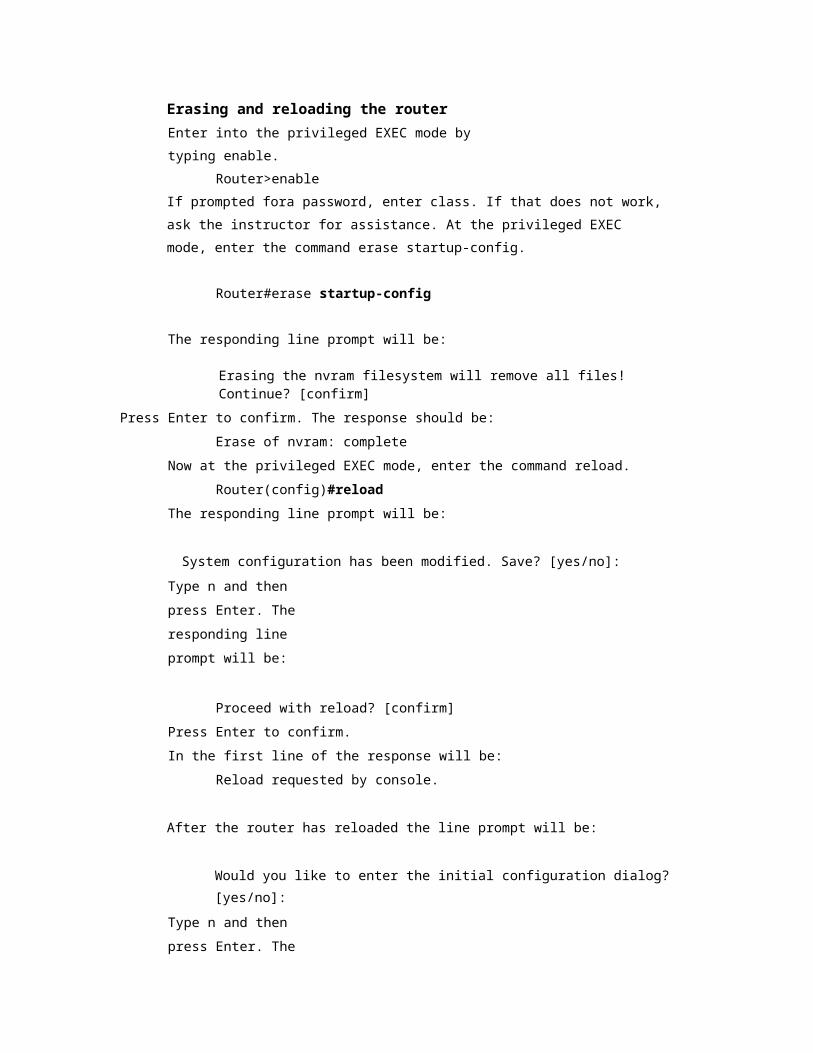
Erasing and reloading the router Enter into the privileged EXEC mode by typing enable.
Router>enable
If prompted for a password, enter class. If that does not work, ask the instructor for assistance. At the privileged EXEC mode, enter the command erase startup-config.
Router#erase startup-config The responding line prompt will be:
Erasing the nvram filesystem will remove all files! Continue? [confirm]
Press Enter to confirm. The response should be:
Erase of nvram: complete Now at the privileged EXEC mode, enter the command reload.
Router#reload The responding line prompt will be:
System configuration has been modified. Save? [yes/no]: Type n and then press Enter. The responding line prompt will be:
Proceed with reload?
[confirm] Press Enter to confirm. In the
first line of the response will be:
Reload requested by console. After
the router has reloaded the line prompt will
be:
Would you like to enter the initial configuration dialog? [yes/no]: Type
n and then press Enter. The responding line prompt will be:
Press RETURN to get started!
Press Enter. Now the router is ready for the
assigned lab to be performed.
5 -6 CCNA 3: Switching Basics and Intermediate Routing v 3.1 -Lab 1.2.6 Copyright © 2003, Cisco Systems, Inc.
Router Interface Summary

Router Model Ethernet Interface #1 Ethernet Interface #2 Serial Interface #1
Serial Interface #2
800 (806) Ethernet 0 (E0) Ethernet 1 (E1) 1600 Ethernet 0 (E0) Ethernet 1 (E1) Serial 0 (SO) Serial 1 (S1) 1700 FastEthernet 0 (FA0) FastEthernet 1 (FA1) Serial 0 (SO) Serial 1 (S1) 2500 Ethernet 0 (E0) Ethernet 1 (E1) Serial 0 (SO) Serial 1 (S1) 2600 FastEthernet 0/0
(FA0/0) FastEthernet 0/1 (FA0/1)
Serial 0/0 (S0/0)
Serial 0/1 (S0/1)
In order to find out exactly how the router is configured, look at the interfaces. This will identify what type and how many interfaces the router has. There is no way to effectively list all of the combinations of configurations for each router class. What is provided are the identifiers for the possible combinations of interfaces in the device. This interface chart does not include any other type of interface even though a specific router may contain one. An example of this might be an ISDN BRI interface. The string in parenthesis is the legal abbreviation that can be used in IOS command to represent the interface.
6-6 CCNA3: Switching Basics and Intermediate Routing v 3.1 -Lab 1.2.6 Copyright © 2003, Cisco Systems, Inc.

ClSCJ StSTEHS