Embed Size (px)
Citation preview
San Francisco • Paris • Düsseldorf • Soest • London
CCDP
™
: Cisco
®
Internetwork Design Study Guide
Robert Padjen with Todd Lammle

Associate Publisher: Neil EddeContracts and Licensing Manager: Kristine O’CallaghanAcquisitions & Developmental Editor: Linda LeeAssociate Developmental Editor: Dann McDormanEditors: Linda Recktenwald and Emily K. Wolman Project Editor: Julie SakaueTechnical Editors: David Rajala and Lance SkokBook Designer: Bill GibsonGraphic Illustrator: Tony JonickElectronic Publishing Specialist: Nila NicholsProject Team Leader: Shannon MurphyProofreaders: Patrick J. Peterson, Dave Nash, Alison Moncrieff, and Laurie O’ConnellIndexer: Ted LauxCD Coordinator: Kara SchwartzCD Technician: Keith McNeilCover Designer: Archer DesignCover Illustrator/Photographer: Tony Stone Images
SYBEX and the SYBEX logo are trademarks of SYBEX Inc. in the USA and other countries.
Screen reproductions produced with Collage Complete.Collage Complete is a trademark of Inner Media Inc.
The CD interface was created using Macromedia Director, © 1994, 1997-1999 Macromedia Inc. For more information on Macromedia and Macromedia Director, visit http://www.macromedia.com.
This study guide and/or material is not sponsored by, endorsed by or affiliated with Cisco Systems, Inc. Cisco®, Cisco Sys-tems®, CCDA™, CCNA™, CCDP™, CCNP™, CCIE™, CCSI™, the Cisco Systems logo and the CCIE logo are trademarks or registered trademarks of Cisco Systems, Inc. in the United States and certain other countries. All other trademarks are trademarks of their respective owners.
TRADEMARKS: SYBEX has attempted throughout this book to distinguish proprietary trademarks from descriptive terms by following the capitalization style used by the manufacturer.
The author and publisher have made their best efforts to prepare this book, and the content is based upon final release soft-ware whenever possible. Portions of the manuscript may be based upon pre-release versions supplied by software manu-facturer(s). The author and the publisher make no representation or warranties of any kind with regard to the completeness or accuracy of the contents herein and accept no liability of any kind including but not limited to performance, merchant-ability, fitness for any particular purpose, or any losses or damages of any kind caused or alleged to be caused directly or indirectly from this book.
Copyright © 2000 SYBEX Inc., 1151 Marina Village Parkway, Alameda, CA 94501. World rights reserved. No part of this publication may be stored in a retrieval system, transmitted, or reproduced in any way, including but not limited to photo-copy, photograph, magnetic, or other record, without the prior agreement and written permission of the publisher.
Library of Congress Card Number: 99-69764
ISBN: 0-7821-2639-1
Manufactured in the United States of America
10 9 8 7 6 5 4 3 2 1
Software License Agreement: Terms and Conditions
The media and/or any online materials accompanying this book that are available now or in the future contain pro-grams and/or text files (the “Software”) to be used in connec-tion with the book. SYBEX hereby grants to you a license to use the Software, subject to the terms that follow. Your pur-chase, acceptance, or use of the Software will constitute your acceptance of such terms.The Software compilation is the property of SYBEX unless otherwise indicated and is protected by copyright to SYBEX or other copyright owner(s) as indicated in the media files (the “Owner(s)”). You are hereby granted a single-user license to use the Software for your personal, noncommercial use only. You may not reproduce, sell, distribute, publish, circulate, or commercially exploit the Software, or any por-tion thereof, without the written consent of SYBEX and the specific copyright owner(s) of any component software included on this media.In the event that the Software or components include specific license requirements or end-user agreements, statements of condition, disclaimers, limitations or warranties (“End-User License”), those End-User Licenses supersede the terms and conditions herein as to that particular Software component. Your purchase, acceptance, or use of the Software will con-stitute your acceptance of such End-User Licenses.By purchase, use or acceptance of the Software you further agree to comply with all export laws and regulations of the United States as such laws and regulations may exist from time to time.
Software Support
Components of the supplemental Software and any offers associated with them may be supported by the specific Owner(s) of that material but they are not supported by SYBEX. Information regarding any available support may be obtained from the Owner(s) using the information provided in the appropriate read.me files or listed elsewhere on the media.Should the manufacturer(s) or other Owner(s) cease to offer support or decline to honor any offer, SYBEX bears no responsibility. This notice concerning support for the Soft-ware is provided for your information only. SYBEX is not the agent or principal of the Owner(s), and SYBEX is in no way responsible for providing any support for the Software, nor is it liable or responsible for any support provided, or not pro-vided, by the Owner(s).
Warranty
SYBEX warrants the enclosed media to be free of physical defects for a period of ninety (90) days after purchase. The Software is not available from SYBEX in any other form or media than that enclosed herein or posted to
www.sybex.com
. If you discover a defect in the media during this warranty period, you may obtain a replacement of identical format at
no charge by sending the defective media, postage prepaid, with proof of purchase to:
SYBEX Inc.Customer Service Department1151 Marina Village ParkwayAlameda, CA 94501(510) 523-8233Fax: (510) 523-2373e-mail: [email protected]: HTTP://WWW.SYBEX.COM
After the 90-day period, you can obtain replacement media of identical format by sending us the defective disk, proof of purchase, and a check or money order for $10, payable to SYBEX.
Disclaimer
SYBEX makes no warranty or representation, either expressed or implied, with respect to the Software or its con-tents, quality, performance, merchantability, or fitness for a particular purpose. In no event will SYBEX, its distributors, or dealers be liable to you or any other party for direct, indi-rect, special, incidental, consequential, or other damages arising out of the use of or inability to use the Software or its contents even if advised of the possibility of such damage. In the event that the Software includes an online update feature, SYBEX further disclaims any obligation to provide this fea-ture for any specific duration other than the initial posting.The exclusion of implied warranties is not permitted by some states. Therefore, the above exclusion may not apply to you. This warranty provides you with specific legal rights; there may be other rights that you may have that vary from state to state. The pricing of the book with the Software by SYBEX reflects the allocation of risk and limitations on liability con-tained in this agreement of Terms and Conditions.
Shareware Distribution
This Software may contain various programs that are distrib-uted as shareware. Copyright laws apply to both shareware and ordinary commercial software, and the copyright Owner(s) retains all rights. If you try a shareware program and continue using it, you are expected to register it. Individ-ual programs differ on details of trial periods, registration, and payment. Please observe the requirements stated in appropriate files.
Copy Protection
The Software in whole or in part may or may not be copy-protected or encrypted. However, in all cases, reselling or redistributing these files without authorization is expressly forbidden except as specifically provided for by the Owner(s) therein.

Acknowledgments
I
want to thank my family for their patience and assistance in this effort.
Kris, I love you, it's as simple as that.Eddie and Tyler, you're both fascinating and I learn more from each of
you each day. I love you both very much.I also need to thank:
�
Bob Collins
�
Sean Stinson, Deb McMahon, Theran Lee, and the Schwabies
�
George, Steve, Milind, and the rest of the Cisco kids
While there are times where I don’t know if I should thank him or kick him, I need to acknowledge Todd for making my life even more of a hectic event.
Thanks to all of the copy editors and technical editors—there were a lot. A special note of thanks to Dave, who kept me on my toes and challenged me to the point of irritation, and Emily, who may have persuaded me to never go down to Australia. It’s a better book because of all of the editors, and I am grateful for their insight and diligence. I also want to thank Julie, Linda R., Lance S., Dann, Neil, and Linda L. for their assistance.
Then, of course, there is the whole Production crew—Shannon M., Nila N., Tony J., Keith M., Kara S., Patrick P., Dave N., Alison M., and Laurie O. Without them, this book would be nothing but a bunch of files.
Introduction
T
his book is intended to help you continue on your exciting new path toward obtaining your CCDP and CCIE certification. Before reading this book, it is important to have at least studied the Sybex
CCNA Study Guide.
You can take the tests in any order, but the CCNA exam should probably be your first test. It would also be beneficial to have read the Sybex
ACRC Study Guide
. Many questions in the CID exam build upon the CCNA and ACRC material. We’ve done everything possible to make sure that you can pass the CID exam by reading this book and practicing with Cisco routers and switches. Note that compared to most other Cisco certifications, the CID exam is more theoretical. Practical experience will help you, especially in regard to Chapters 3, 4, 5, 6, 7, and 10. You’ll benefit from hands-on experience in the other chapters, but to a lesser degree.
Cisco—A Brief History
Many readers may already be familiar with Cisco and what it does. How-ever, the story of the company’s creation and evolution is quite interesting.
In the early 1980s, Len and Sandy Bosack worked in different computer departments at Stanford University and started cisco Systems (notice the small
c
)
.
They were having trouble getting their individual systems to com-municate (like some married people), so they created a gateway server in their living room to make it easier for their disparate computers in two dif-ferent departments to communicate using the IP protocol.
In 1984, Cisco Systems was founded with a small commercial gateway server product that changed networking forever. Some people think that the name was intended to be San Francisco Systems, but that the paper got ripped on the way to the incorporation lawyers—who knows? But in 1992, the company name was changed to Cisco Systems, Inc.
The first product it marketed was called the Advanced Gateway Server (AGS). Then came the Mid-Range Gateway Server (MGS), the Compact Gateway Server (CGS), the Integrated Gateway Server (IGS), and the AGS+. Cisco calls these “the old alphabet soup products.”
In 1993, Cisco came out with the then-amazing 4000 router, and later created the even more amazing 7000, 2000, and 3000 series routers. While the product line has grown beyond the technologies found in these plat-forms, the products still owe a substantial debt of gratitude to these early
xx
Introduction
systems. Today’s GSR product can forward millions more packets than the 7000, for example. Cisco Systems has since become an unrivaled worldwide leader in networking for the Internet. Its networking solutions can easily connect users who work from diverse devices on disparate networks. Cisco products make it simple for people to access and transfer information with-out regard to differences in time, place, or platform.
Cisco Systems’ big picture is that it provides end-to-end networking solu-tions that customers can use to build an efficient, unified information infra-structure of their own or to connect to someone else’s. This is an important piece in the Internet/networking-industry puzzle because a common archi-tecture that delivers consistent network services to all users is now a func-tional imperative. Because Cisco Systems offers such a broad range of networking and Internet services and capabilities, users needing regular access to their local network or the Internet can do so unhindered, making Cisco’s wares indispensable. The company has also challenged the industry by acquiring and integrating other technologies into its own.
Cisco answers users’ need for access with a wide range of hardware prod-ucts that are used to form information networks using the Cisco Internet Operating System (IOS) software. This software provides network services, paving the way for networked technical support and professional services to maintain and optimize all network operations.
Along with the Cisco IOS, one of the services Cisco created to help sup-port the vast amount of hardware it has engineered is the Cisco Certified Internetworking Expert (CCIE) program, which was designed specifically to equip people to manage effectively the vast quantity of installed Cisco net-works. The business plan is simple: If you want to sell more Cisco equipment and have more Cisco networks installed, you must ensure that the networks you installed run properly.
However, having a fabulous product line isn’t all it takes to guarantee the huge success that Cisco enjoys—lots of companies with great products are now defunct. If you have complicated products designed to solve compli-cated problems, you need knowledgeable people who are fully capable of installing, managing, and troubleshooting them. That part isn’t easy, so Cisco began the CCIE program to equip people to support these complicated networks. This program, known colloquially as the Doctorate of Network-ing, has also been very successful, primarily due to its stringent standards. Cisco continuously monitors the program, changing it as it sees fit, to make sure that it remains pertinent and accurately reflects the demands of today’s internetworking business environments.
Introduction
xxi
Building upon the highly successful CCIE program, Cisco Career Certifi-cations permit you to become certified at various levels of technical profi-ciency, spanning the disciplines of network design and support. So, whether you’re beginning a career, changing careers, securing your present position, or seeking to refine and promote your position, this is the book for you!
Cisco’s Network Support Certifications
Cisco has created new certifications that will help you get the coveted CCIE, as well as aid prospective employers in measuring skill levels. Before these new certifications, you took only one test and were then faced with the lab, which made it difficult to succeed. With these new certifications that offer a better approach to preparing for that almighty lab, Cisco has opened doors that few were allowed through before. So, what are these new certifications, and how do they help you get your CCIE?
Cisco Certified Network Associate (CCNA)
The CCNA certification is the first in the new line of Cisco certifications, and it is a precursor to all current Cisco network support certifications. With the new certification programs, Cisco has created a type of stepping-stone approach to CCIE certification. Now, you can become a Cisco Certified Net-work Associate for the meager cost of the Sybex
CCNA Study Guide,
plus $100 for the test. And you don’t have to stop there—you can choose to con-tinue with your studies and achieve a higher certification called the Cisco Certified Network Professional (CCNP). Someone with a CCNP has all the skills and knowledge required to attempt the CCIE lab. However, because no textbook can take the place of practical experience, we’ll discuss what else you need to be ready for the CCIE lab shortly.
Why Become a CCNA?
Cisco has created the certification process, not unlike those of Microsoft or Novell, to give administrators a set of skills and to equip prospective employers with a way to measure skills or match certain criteria. Becoming a CCNA can be the initial step of a successful journey toward a new, highly reward-ing, and sustainable career.
The CCNA program was created to provide a solid introduction not only to the Cisco Internet Operating System (IOS) and Cisco hardware, but to internetworking in general. This program can provide some help in
xxii
Introduction
understanding networking areas that are not exclusively Cisco’s. At this point in the certification process, it’s not unrealistic to imagine that future network managers—even those without Cisco equipment—could easily require Cisco certifications for their job applicants.
If you make it through the CCNA and are still interested in Cisco and internetworking, you’re headed down a path to certain success.
To meet the CCNA certification skill level, you must be able to do the following:
�
Install, configure, and operate simple-routed LAN, routed WAN, and switched LAN and LANE networks.
�
Understand and be able to configure IP, IGRP, IPX, Serial, AppleTalk, Frame Relay, IP RIP, VLANs, IPX RIP, Ethernet, and access lists.
�
Install and/or configure a network.
�
Optimize WAN through Internet-access solutions that reduce band-width and WAN costs, using features such as filtering with access lists, bandwidth on demand (BOD), and dial-on-demand routing (DDR).
�
Provide remote access by integrating dial-up connectivity with tradi-tional remote LAN-to-LAN access, as well as supporting the higher levels of performance required for new applications such as Internet commerce, multimedia, etc.
How Do You Become a CCNA?
The first step is to pass one “little” test and poof—you’re a CCNA! (Don’t you wish it were that easy?) True, it’s just one test, but you still have to pos-sess enough knowledge to understand (and read between the lines—trust us) what the test writers are saying.
We can’t say this enough—it’s critical that you have some hands-on expe-rience with Cisco routers. If you can get hold of some 2500 routers, you’re set. But in case you can’t, we’ve worked hard to provide hundreds of config-uration examples throughout the Sybex
CCNA Study Guide
book to help network administrators (or people who want to become network adminis-trators) learn what they need to know to pass the CCNA exam.
One way to get the hands-on router experience you’ll need in the real world is to attend one of the seminars offered by GlobalNet System Solu-tions, Inc. Please check
www.lammle.com
for more information and free router giveaways every month! Cyberstate University also provides hands-on
Introduction
xxiii
Cisco router courses over the Internet using the Sybex Cisco Certification series books. Go to
www.cyberstateu.com
for more information. In addi-tion, Keystone Learning Systems (
www.klscorp.com
) offers the popular Cisco video certification series, featuring Todd Lammle.
For online access to Cisco equipment, readers should take a look at
www.virtualrack.com
.It can also be helpful to take an Introduction to Cisco Router Configura-
tion (ICRC) course at an authorized Cisco Education Center, but you should understand that this class doesn’t meet all of the test objectives. If you decide to take the course, reading the Sybex
CCNA Study Guide
, in conjunction with the hands-on course, will give you the knowledge that you need for certification.
A Cisco router simulator that allows you to practice your routing skills for preparation of your Cisco exams is available at
www.routersim.com.
For additional practice exams for all Cisco certification courses, please visit
www.boson.com
.
Cisco Certified Network Professional (CCNP)
This Cisco certification has opened up many opportunities for the individual wishing to become Cisco-certified, but who is lacking the training, the exper-tise, or the bucks to pass the notorious and often-failed two-day Cisco torture lab. The new Cisco certification will truly provide exciting new opportunities for the CNE and MCSE who just don’t know how to advance to a higher level.
So, you’re thinking, “Great, what do I do after I pass the CCNA exam?” Well, if you want to become a CCIE in Routing and Switching (the most pop-ular certification), understand that there’s more than one path to that much-coveted CCIE certification. The first way is to continue studying and become a CCNP. That means four more tests—and the CCNA certification—to you.
The CCNP program will prepare you to understand and comprehensively tackle the internetworking issues of today and beyond—not just those lim-ited to the Cisco world. You will undergo an immense metamorphosis, vastly increasing your knowledge and skills through the process of obtaining these certifications.
Remember that you don’t need to be a CCNP or even a CCNA to take the CCIE lab, but it’s extremely helpful if you already have these certifications.
xxiv
Introduction
What Are the CCNP Certification Skills?
Cisco demands a certain level of proficiency for its CCNP certification. In addition to those skills required for the CCNA, these skills include the following:
�
Installing, configuring, operating, and troubleshooting complex routed LAN, routed WAN, and switched LAN networks, and Dial Access Services.
�
Understanding complex networks, such as IP, IGRP, IPX, Async Routing, AppleTalk, extended access lists, IP RIP, route redistribu-tion, IPX RIP, route summarization, OSPF, VLSM, BGP, Serial, IGRP, Frame Relay, ISDN, ISL, X.25, DDR, PSTN, PPP, VLANs, Ethernet, ATM LAN emulation, access lists, 802.10, FDDI, and transparent and translational bridging.
To meet the Cisco Certified Network Professional requirements, you must be able to perform the following:
�
Install and/or configure a network to increase bandwidth, quicken network response times, and improve reliability and quality of service.
�
Maximize performance through campus LANs, routed WANs, and remote access.
�
Improve network security.
�
Create a global intranet.
�
Provide access security to campus switches and routers.
�
Provide increased switching and routing bandwidth—end-to-end resiliency services.
�
Provide custom queuing and routed priority services.
How Do You Become a CCNP?
After becoming a CCNA, the four exams you must take to get your CCNP are as follows:
�
Exam 640-503:
Routing continues to build on the fundamentals learned in the ICND course. It focuses on large multiprotocol inter-networks and how to manage them with access lists, queuing, tunnel-ing, route distribution, route summarization, and dial-on-demand.
Introduction
xxv
�
Exam 640-504:
Switching tests your understanding of configuring, monitoring, and troubleshooting the Cisco 1900 and 5000 Catalyst switching products.
�
Exam 640-505:
Remote Access tests your knowledge of installing, configuring, monitoring, and troubleshooting Cisco ISDN and dial-up access products.
�
Exam 640-506:
Support tests you on the troubleshooting information you learned in the other Cisco courses.
If you hate tests, you can take fewer of them by signing up for the CCNA exam and the Support exam, and then taking just one more long exam called the Foundation R/S exam (640-509). Doing this also gives you your CCNP—but beware, it’s a really long test that fuses all the material listed previously into one exam. Good luck! However, by taking this exam, you get three tests for the price of two, which saves you $100 (if you pass). Some people think it’s easier to take the Foundation R/S exam because you can leverage the areas in
which you score higher against the areas in which you score lower.
Remember that test objectives and tests can change at any time without notice. Always check the Cisco Web site for the most up-to-date information
(
www.cisco.com
).
Cisco Certified Internetwork Expert (CCIE)
You’ve become a CCNP, and now you’ve fixed your sights on getting your CCIE in Routing and Switching—what do you do next? Cisco recommends that before you take the lab, you take test 640-025, Cisco Internetwork Design (CID), and the Cisco authorized course called Installing and Main-taining Cisco Routers (IMCR). By the way, no Prometric test for IMCR exists at the time of this writing, and Cisco recommends a
minimum
of two years of on-the-job experience before taking the CCIE lab. After jumping those hurdles, you then have to pass the CCIE-R/S Exam Qualification (exam 350-001) before taking the actual lab.
xxvi
Introduction
To become a CCIE, Cisco recommends the following:
1.
Attend all the recommended courses at an authorized Cisco training center and pony up around $15,000–$20,000, depending on your cor-porate discount.
2.
Pass the Drake/Prometric exam ($200 per exam—so let’s hope you’ll pass it the first time).
3.
Pass the two-day, hands-on lab at Cisco. This costs $1,000 per lab, which many people fail two or more times. (Some never make it through!) Also, because you can take the exam only in San Jose, Cal-ifornia; Research Triangle Park, North Carolina; Sydney, Australia; Halifax, Nova Scotia; Tokyo, Japan; or Brussels, Belgium, you might need to add travel costs to this figure.
The CCIE Skills
The CCIE Router and Switching exam includes the advanced technical skills that are required to maintain optimum network performance and reliability, as well as advanced skills in supporting diverse networks that use disparate technologies. CCIEs have no problems getting a job. These experts are basi-cally inundated with offers to work for six-figure salaries! But that’s because it isn’t easy to attain the level of capability that is mandatory for Cisco’s CCIE. For example, a CCIE will have the following skills down pat:
�
Installing, configuring, operating, and troubleshooting complex routed LAN, routed WAN, switched LAN, and ATM LANE net-works, and Dial Access Services.
�
Diagnosing and resolving network faults.
�
Using packet/frame analysis and Cisco debugging tools.
�
Documenting and reporting the problem-solving processes used.
�
Having general LAN/WAN knowledge, including data encapsulation and layering; windowing and flow control and their relation to delay; error detection and recovery; link-state, distance-vector, and switch-ing algorithms; and management, monitoring, and fault isolation.
�
Having knowledge of a variety of corporate technologies—including major services provided by Desktop, WAN, and Internet groups—as well as the functions, addressing structures, and routing, switching, and bridging implications of each of their protocols.
Introduction
xxvii
�
Having knowledge of Cisco-specific technologies, including router/ switch platforms, architectures, and applications; communication servers; protocol translation and applications; configuration com-mands and system/network impact; and LAN/WAN interfaces, capa-bilities, and applications.
Cisco’s Network Design Certifications
In addition to the Network Support certifications, Cisco has created another certification track for network designers. The two certifications within this track are the Cisco Certified Design Associate and Cisco Certified Design Professional certifications. If you’re reaching for the CCIE stars, we highly recommend the CCNP and CCDP certifications before attempting the lab (or attempting to advance your career).
These certifications will give you the knowledge to design routed LAN, routed WAN, and switched LAN and ATM LANE networks.
Cisco Certified Design Associate (CCDA)
To become a CCDA, you must pass the DCN (Designing Cisco Networks) test (640-441). To pass this test, you must understand how to do the following:
�
Design simple routed LAN, routed WAN, and switched LAN and ATM LANE networks.
�
Use network-layer addressing.
�
Filter with access lists.
�
Use and propagate VLAN.
�
Size networks.
The Sybex
CCDA Study Guide
is the most cost-effective way to study for and
pass your CCDA exam.
Cisco Certified Design Professional (CCDP)
It is surprising that the Cisco’s CCDP track has not garnered the response of the other certifications. It is also ironic, because many of the higher paying
xxviii
Introduction
jobs in networking focus on design. In addition, the other certifications, including the CCIE, tend to focus more on laboratory scenarios and problem resolution, while the CCDP and CID exams look more at problem preven-tion. It is important to note that Cisco highly recommends the CID exami-nation for people planning to take the CCIE written exam.
What Are the CCDP Certification Skills?
CCDP builds upon the concepts introduced at the CCDA level, but adds the following skills:
�
Designing complex routed LAN, routed WAN, and switched LAN and ATM LANE networks.
�
Building upon the base level of the CCDA technical knowledge.
CCDPs must also demonstrate proficiency in the following:
�
Network-layer addressing in a hierarchical environment.
�
Traffic management with access lists.
�
Hierarchical network design.
�
VLAN use and propagation.
�
Performance considerations, including required hardware and soft-ware, switching engines, memory, cost, and minimization.
How Do You Become a CCDP?
Attaining your CCDP certification is a fairly straightforward process, although Cisco provides two different testing options once a candidate passes the CCDA examination (640-441), which covers the basics of design-ing Cisco networks, and the CCNA (640-507). Applicants may then take a single Foundation Exam (640-509) or the three individual exams that the Foundation Exam replaces: Routing, Switching, and Remote Access (640-503, 640-504, and 640-505, respectively). The Foundation Exam will save you some money if you pass, but it is a much longer test that encompasses the material presented in the three other examinations. Note that the CCNP requires these same tests, except for the CCDA.
Following these two certifications and the noted exams, applicants must pass only the CID examination (640-025) to earn their CCDP. In the pro-cess, applicants will have earned three different certifications. Furthermore, many of the tests are applicable to the CCNP certification track.
Introduction
xxix
What Does This Book Cover?
This book covers everything you need to pass the CCDP: Cisco Internetwork Design exam. In concert with the objectives, the exam is designed to test your knowledge of theoretical network design criteria and the practical applica-tion of that material. Each chapter begins with a list of the CCDP: CID test objectives covered.
Chapter 1 provides an introduction to network design and presents the design models that are used in the industry, including the hierarchical model. The benefits and detriments of these models are discussed.
The tools used in network designs are introduced in Chapter 2. These include switches, routers, hubs, and repeaters.
Chapter 3 addresses the IP protocol and the many challenges that can con-front the network designer, including variable-length subnet masks and IP address conservation.
The various IP routing protocols are presented in Chapter 4, including IGRP, EIGRP, and OSPF. This chapter is augmented with information on ODR and new routing techniques that are becoming important for the modern network designer.
Chapter 5 presents AppleTalk networking, including the benefits and det-riments of the protocol. It is important to note that while the AppleTalk pro-tocol is losing market share in production networks, it is still covered in the CID exam.
Chapter 6 focuses on Novell networking and the IPX protocol. Like AppleTalk, IPX provides the designer with many benefits. The protocol is also being slowly phased out in favor of IP, but, like AppleTalk, it is still part of the CID examination.
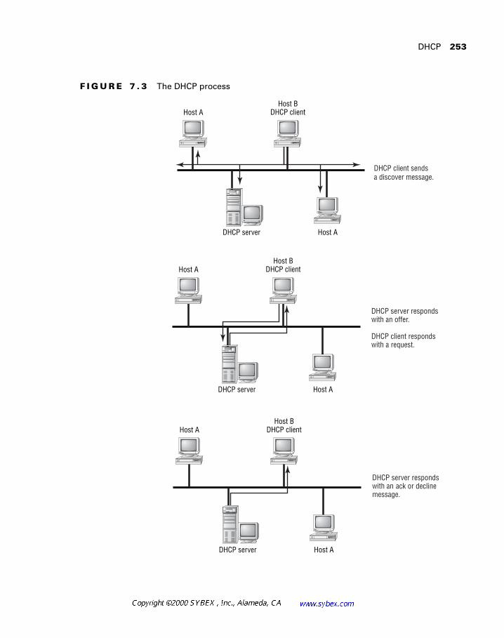
Windows networking and the NetBIOS protocol are presented in Chapter 7. This popular operating system requires knowledge of address and name management (DHCP, WINS, and DNS), in addition to an understanding of the protocols that can transport NetBIOS packets, including IPX, IP, and NetBEUI. The issue of broadcasts in desktop protocols is also covered in this chapter.
Chapter 8 presents the wide-area network (WAN) technologies, including SMDS, Frame Relay, and ATM. This presentation focuses on the character-istics of each technology.
Chapter 9 addresses the remote-access technologies, including asynchro-nous dial-up, ISDN, and X.25. In addition, this chapter adds to the Cisco objectives by including DSL and cable-modem technologies.
xxx
Introduction
SNA networking and mainframes are covered in Chapter 10. This chapter introduces the ways to integrate SNA networks into modern, large-scale routed environments, using technologies including STUN, RSRB, DSLW+, and APPN.
Chapter 11 focuses on security as a component of network design. This includes the placement and use of firewalls and access lists in the network.
Chapter 12 summarizes the text and provides an overview of the network management.
Chapter 13 departs from the somewhat dated CID exam objectives and introduces a few of the more current issues and challenges facing modern network designers. This section covers IP multicast, VPN technology, and encryption.
Within each chapter there are a number of sidebars titled “Network Design in the Real World.” This material may either augment the main text or present additional information that can assist the network designer in applying the material. Each chapter ends with review questions that are spe-cifically designed to help you retain the knowledge presented.
We’ve included an objective map on the inside front cover of this book that helps you find all the information relevant to each objective in this book. Keep in mind that all of the actual exam objectives covered in a particular chapter
are listed at the beginning of that chapter.
Where Do You Take the Exam?
You may take the exams at any of the more than 800 Sylvan Prometric Authorized Testing Centers around the world. For the location of a test-ing center near you, call (800) 755-3926, or go to their Web site at
www.2test.com
. Outside of the United States and Canada, contact your local Sylvan Prometric Registration Center.
To register for a Cisco Certified Network Professional exam:
1.
Determine the number of the exam you want to take. (The CID exam number is 640-025.)
2. Register with the nearest Sylvan Prometric Registration Center. At this point, you will be asked to pay in advance for the exam. At the time of this writing, the exams are $100 each and must be taken within one

Introduction xxxi
year of payment. You can schedule exams up to six weeks in advance or as soon as one working day prior to the day you wish to take it. If you need to cancel or reschedule your exam appointment, contact Syl-van Prometric at least 24 hours in advance. Same-day registration isn’t available for the Cisco tests.
3. When you schedule the exam, you’ll get instructions regarding all appointment and cancellation procedures, the ID requirements, and information about the testing-center location.
Tips for Taking Your CID Exam
The CCDP CID test contains about 100 questions to be completed in 90 minutes. You must schedule a test at least 24 hours in advance (unlike the Novell or Microsoft exams), and you aren’t allowed to take more than one Cisco exam per day.
Unlike Microsoft or Novell tests, the exam has answer choices that are really similar in syntax—although some syntax is dead wrong, it is usually just subtly wrong. Some other syntax choices may be right, but they’re shown in the wrong order. Cisco does split hairs and is not at all averse to giving you classic trick questions.
Also, never forget that the right answer is the Cisco answer. In many cases, more than one appropriate answer is presented, but the correct answer is the one that Cisco recommends.
Here are some general tips for exam success:
� Arrive early at the exam center, so you can relax and review your study materials.
� Read the questions carefully. Don’t just jump to conclusions. Make sure that you’re clear about exactly what each question asks.
� Don’t leave any questions unanswered. They count against you.
� When answering multiple-choice questions that you’re not sure about, use a process of elimination to get rid of the obviously incorrect answers first. Doing this greatly improves your odds if you need to make an educated guess.
� As of this writing, the CID exam permits skipping questions and reviewing previous answers. However, this is changing on all Cisco exams, and so you should prepare as though this option will not be available.

xxxii Introduction
After you complete an exam, you’ll get immediate, online notification of your pass or fail status, a printed Examination Score Report that indicates your pass or fail status, and your exam results by section. (The test admin-istrator will give you the printed score report.) Test scores are automatically forwarded to Cisco within five working days after you take the test, so you don’t need to send your score to them. If you pass the exam, you’ll receive confirmation from Cisco, typically within two to four weeks.
Appendix C lists a number of additional Web sites that can further assist you with research and test questions.
How to Use This Book
This book can provide a solid foundation for the serious effort of preparing for the Cisco Certified Network Professional CID (Cisco Internetwork Design) exam. To best benefit from this book, use the following study method:
1. Study each chapter carefully, making sure that you fully understand the information and the test objectives listed at the beginning of each chapter.
2. Answer the review questions related to that chapter. (The answers are in Appendix A.)
3. Note the questions that confuse you, and study those sections of the book again.
4. Before taking the exam, try your hand at the practice exams that are included on the CD that comes with this book. They’ll give you a com-plete overview of what you can expect to see on the real thing. Note that the CD contains questions not included in the book.
5. Remember to use the products on the CD that is included with this book. Visio, EtherPeek, and the EdgeTest exam-preparation soft-ware have all been specifically picked to help you study for and pass your exam.
To learn all the material covered in this book, you’ll have to apply your-self regularly and with discipline. Try to set aside the same time period

Introduction xxxiii
every day to study, and select a comfortable and quiet place to do so. If you work hard, you will be surprised at how quickly you learn this material. All the best!
What’s on the CD?
We worked hard to provide some really great tools to help you with your cer-tification process. All of the following components should be loaded on your workstation when studying for the test.
The EdgeTest for Cisco CID Test Preparation Software
Provided by EdgeTek Learning Systems, this test-preparation software pre-pares you to pass the Cisco Internetwork Design exam. To find more test-simulation software for all Cisco and NT exams, look for the exam link on www.lammle.com.
AG Group NetTools and EtherPeek
Two AG Group products appear on the CD that accompanies this book: EtherPeek for Windows demonstration software (which requires a serial number) and the freeware version of AG NetTools. EtherPeek is a full-featured, affordable packet and network analyzer. AG NetTools is an interface- and menu-driven IP tool compilation.
The serial numbers are included in the readme file located on the CD. You can find out more information about AG Group and purchase the license for EtherPeek and other products at www.aggroup.com.
How to Contact the Authors
To reach Robert Padjen, send him e-mail at [email protected]. Robert provides consulting services to a wide variety of clients, including Charles Schwab and the California State Automobile Association.
You can reach Todd Lammle through GlobalNet Training Solutions, Inc. (www.lammle.com)—his Training and Systems Integration Company in Colorado—or e-mail him at [email protected].

Assessment Test
1. A LANE installation requires what three components?
2. In modern networks, SNA is a disadvantage because of what limitation?
3. The native, non-routable encapsulation for NetBIOS is _______.
4. The FEP runs VTAM. True or false?
5. Switches operate at ______ of the OSI model.
6. ATM uses ________ in AAL 5 encapsulation.
7. Clients locate the server in Novell networks by sending a _________ request.
8. Most network management tools use ______ to communicate with devices.
9. The address 127.50.0.14 is part of what class?
10. The formula for determining the number of circuits needed for a full-mesh topology is ______________.
11. A remote gateway provides support for ________ application/applications.
12. An IP network with a mask of 255.255.255.252 supports how many hosts per subnet?
13. ISDN BRI provides _________.
14. The RIF is part of a/an ____________ frame.
15. Local acknowledgment provides _______________ system response for remote nodes.

Assessment Test xxxv
16. OSPF is a _______________ protocol.
17. AppleTalk networks automatically define the node number. The administrator or designer assigns a _____________ to define the net-work number.
18. EIGRP does not support variable length subnet masks. True or false?
19. It is most practical to establish a remote ________ configuration so that all services are available to remote users.
20. RSRB allows SNA traffic to traverse non-____________ segments.
21. Networks with a core, access, and distribution layer are called _______.
22. Multilink Multichassis PPP uses what proprietary protocol?
23. Hub-and-spoke networks could also be called ________.
24. What datagrams are typically forwarded with the ip helper-address command?
25. Type 20 packets are used for what function?
26. A user operates a session running on a remote workstation or server from home as if they were physically there. What is this called?
27. What is Cisco’s product for IPX-to-IP gateway services called?
28. What is the routing protocol of the Internet?
29. What is a link with 2B and 1D channels called?
30. Multicast addresses are part of what class?
31. Information about logical groupings in AppleTalk is contained in __________.

xxxvi Assessment Test
32. What are L2TP, IPSec, and L2F typically used for?
33. TACACS+ and RADIUS provide what services?
34. What is an FEP?
35. For voice, video, and data integration, designers should use which WAN protocol?
36. What is the default administrative distance for OSPF?
37. Network monitoring relies on what protocol?
38. What is a connection via dial-up, ISDN, or another technology that places a remote workstation on the corporate network as if they were directly connected called?
39. What does HSRP provide the designer?
40. VLSM is supported in which of the following routing protocols?
A. EIGRP
B. IGRP
C. RIP v2
D. RIP v1
E. OSPF

Assessment Test xxxvii
Answers to Assessment Test
1. LES, LEC, and BUS. See Chapter 8.
2. It is not routable. In addition, it is very sensitive to delay. See Chapter 10.
3. NetBEUI. See Chapter 7.
4. False. See Chapter 10.
5. Layer 2. See Chapter 2.
6. 53-byte cells, 48 of which are used for user data. See Chapter 8.
7. Get Nearest Server. See Chapter 6.
8. SNMP. See Chapter 12.
9. None. This network is reserved for the loopback function. See Chapter 3.
10. N * (N–1) / 2. See Chapter 8.
11. A single. See Chapter 9.
12. Two. See Chapter 3.
13. Two B channels of 64Kbps each and one D channel of 16Kbps. See Chapter 9.
14. Token Ring. See Chapter 10.
15. Improved. See Chapter 10.
16. Link-state. See Chapter 4.
17. Cable-range. See Chapter 5.

xxxviii Assessment Test
18. False. See Chapter 4.
19. Node. See Chapter 9.
20. Token Ring. See Chapter 10.
21. Hierarchical. See Chapter 1.
22. Stackgroup Bidding Protocol (SGBP). See Chapter 9.
23. Star. See Chapter 1.
24. DHCP, although this command also forwards seven additional datagrams. See Chapter 7.
25. NetBIOS over IPX. See Chapter 6.
26. Remote control. See Chapter 9.
27. IP eXchange. See Chapter 6.
28. BGP. See Chapter 4.
29. ISDN BRI. See Chapter 9.
30. Class D. See Chapter 13.
31. Zone Information Protocol (ZIP) packets. See Chapter 5.
32. VPNs. See Chapter 9.
33. Centralized authentication. See Chapter 11.
34. A front-end processor for a mainframe. See Chapter 10.
35. ATM. See Chapter 8.
36. 110. See Chapter 4.
37. SNMP. RMON would also be applicable. See Chapter 12.

Assessment Test xxxix
38. Remote node. See Chapter 9.
39. Router redundancy. See Chapter 4.
40. A, C, E. See Chapter 3.
Chapter
1
Introduction to Network Design
CISCO INTERNETWORK DESIGN EXAM OBJECTIVES COVERED IN THIS CHAPTER:
�
Demonstrate an understanding of the steps for designing
internetwork solutions.
�
Analyze a client’s business and technical requirements and
select appropriate internetwork technologies and topologies.
�
Construct an internetwork design that meets a client’s
objectives for internetwork functionality, performance,
and cost.
�
Define the goals of internetwork design.
�
Define the issues facing designers.
�
List resources for further information.
�
Identify the origin of design models used in the course.
�
Define the hierarchical model.
N
etwork design is one of the more interesting facets of com-puting. While there are many disciplines in information technology, includ-ing help desk, application development, project management, workstation support, and server administration, network design is the only one that directly benefits from all these other disciplines. It incorporates elements of many disciplines into a single function. Network designers frequently find that daily challenges require a certain amount of knowledge regarding all of the other IT disciplines.
The network designer is responsible for solving the needs of the business with the technology of the day. This requires knowledge of protocols, oper-ating systems, departmental divisions in the enterprise, and a host of other areas. The majority of network design projects require strong communica-tion skills, leadership, and research and organizational talents. Project man-agement experience can also greatly benefit the process, as most network design efforts will require scheduling and budgeting with internal and exter-nal resources, including vendors, corporate departments, service providers, and the other support and deployment organizations within the enterprise.
This text will both provide an introduction to network design and serve as a reference guide for future projects. Its primary purpose is to present the objectives for the CCDP: Cisco Internetwork Design examination and to prepare readers to pass this certification test. However, it would be unfortu-nate to read this book only in the context of passing the exam. A thorough understanding of network design not only assists administrators in trouble-shooting, but enables them to permanently correct recurrent problems in the network. An additional perk is the satisfaction that comes with seeing a net-work that you designed and deployed—especially a year later when only minor modifications have been needed and all of those were part of your original network design plan.
Overview of Network Design
3
Having said that, it is important to note that in “real world” network designs virtually no individual does all the work. Vendors, business leaders, and other administrators all will, and should, play a significant role in the design process. This is obviously true when planning server-based services, such as DHCP (Dynamic Host Configuration Protocol). Though many beau-tiful network designs have been conceived without consideration and con-sultation of the user community, the end result is an expensive “It should have worked!” After reading this text, and specifically this chapter, no one should ever make this mistake.
Overview of Network Design
I
t has been stated that network design is 50 percent technology, 50 per-cent diplomacy, and 50 percent magic. While written examinations will likely ignore the last item, mastery of the first two is critical in exam preparation.
In actuality, network design is simply the implementation of a technical solution to solve a nontechnical problem. Contrary to expectations, network design is not as basic as configuring a router, although we will address this critical component. Rather, as presented in this first chapter, network design is a multifaceted effort to balance various constraints with objectives.
Network design encompasses three separate areas: conception, imple-mentation, and review. This chapter will elaborate on these areas and expand the scope of each. It’s important to remember that each phase is unique and requires separate attention. The final phase of network design—review—is perhaps more important than any other phase, as it provides valuable information for future network designs and lessons for other projects. Readers should consider how they might design networks deployed with the technology referenced in this text—the easiest methodology is to establish a list of metrics from which to make a comparison. Designers who meet the original metrics for the project usually find that the network is suc-cessful in meeting the customer’s needs.
Each design, whether the simple addition of a subnet or the complete implementation of a new international enterprise network, must address the same goals: scalability, adaptability, cost control, manageability, predict-ability, simplicity of troubleshooting, and ease of implementation. A good design will both address current needs while effectively accommodating
4
Chapter 1 �
Introduction to Network Design
future needs. However, two constraints limit most designs’ ability to address these goals: time and money. Typical network technology lasts only 24 to 60 months, while cabling and other equipment may be
expected
to remain for over 15 years. The most significant constraint, though, will almost always be financial.
The actual expected life of a cable plant is subject to some debate. Many net-works are already coming close to the 15-year mark on the data side, and the voice side already has upwards of 60 years. The trend has been for copper cable to have some built-in longevity, and such efforts as Digital Subscriber Line (DSL), Category 5E, and Gigabit Ethernet over copper are solid evidence that corporations will continue to regard this copper infrastructure as a long-
term investment.
With that said, let’s focus on some of the theory behind network designs.
Network Design Goals
N
etwork designers should strive to address a number of objectives in their designs. Readers should focus on these goals and consider how they might relate to the typical corporate environment. (Later in this chapter, we will more fully explore the importance of the business relationship.) In addi-tion, designers should pay specific attention to the relationships between the design goals, noting that addressing one goal will frequently require com-promising another. Let’s look at these goals in detail.
Scalability
Scalability refers to an implementation’s ability to address the needs of an increasing number of users. For example, a device with only two interfaces will likely not provide as much service and, therefore, not be as scalable as a device with 20. Twenty interfaces will likely cost a great deal more and will undoubtedly require greater amounts of rack space, and so scalability is often governed by another goal—controlling costs. Architects are often chal-lenged to maintain
future-proof
designs while maintaining the budget.
Network Design Goals
5
Factors that augment scalability include high-capacity backbones, switch-ing technology, and modular designs. Additional considerations regarding scalability include the number of devices in the network, CPU utilization, and memory availability. For example, a network with one router is likely to be less scalable than a network with three, even if the three routers are sub-stantially smaller than the one.
Adaptability
While similar to scalability, adaptability need not address an increase in the number of users. An adaptable network is one that can accommodate new services without significant changes to the existing structure, for example, adding voice services into the data network. Designers should consider Asyn-chronous Transfer Mode (ATM) where the potential for this adaptive step exists. For example, the possibility of adding voice service later would negate the use of Fiber Distributed Data Interface (FDDI) in the initial network design. Making this determination requires a certain amount of strategic planning, rather than a purely short-term tactical approach, and could there-fore make a network more efficient and cost-effective. However, this section is not intended to advocate the use of any specific technology, but rather to show the benefits of an adaptable network.
Adaptability is one aspect of network design where using a matrix is ben-eficial. A matrix is a weighted set of criteria, designed to remove subjectivity from the decision-making process. Before reviewing vendors and products, a designer will typically work with managers, executives, and others to con-struct a matrix, assigning a weight to each item. While a complete matrix should include support and cost, a simple matrix could include only the adaptability issues. For example, the use of variable-length subnet masks might be weighted with a five (on a scale from one to five), while support for SNMP (Simple Network Management Protocol) v.3 might only garner a weight of one. Under these conditions, the matrix may point to a router that can support Enhanced Interior Gateway Routing Protocol (EIGRP) or Open Shortest Path First (OSPF) over one with a higher level of manageability, assuming that there is some mutual exclusivity.
6
Chapter 1 �
Introduction to Network Design
Cost Control
Financial considerations often overshadow most other design goal elements. If costs were not an issue, everyone would purchase OC-192 SONET (Syn-chronous Optical Network) rings for their users with new equipment installed every three months. Clearly this is not the “real world.” The net-work designer’s role is often similar to that of a magician—both must fre-quently pull rabbits from their hats, but the network designer has the added responsibility of balancing dollars with functions. Therefore, the designer is confronted with the same cost constraints as all other components of a busi-ness. The fundamental issue at this point must be how to cope with this lim-itation without sacrificing usability. There are a number of methods used in modern network design to address this problem.
First, many companies have a network budget linked to the IT (Informa-tion Technology) department. This budget is typically associated with such basic, general services as baseline costs—wiring, general desktop connectiv-ity, and corporate access to services such as the Internet. There is typically also a second source of funding for the IT department from project-related work. This work comes in the form of departmental requests for service beyond the scope of general service. It may involve setting up a workgroup server or lab environment, or it may involve finding a remote-access solution so that the executives can use a newer technology—DSL, for example. These projects are frequently paid for by the requesting department and not IT. In such cases, the requesting department may even cover costs that are not immediately related to its project. In the DSL project, for example, few com-panies would argue with the logic of setting up a larger scalable installation to address the needs of the few executives using the first generation of the ser-vice. It may be possible to have the requesting department fund all or part of a more-expensive piece of equipment to avoid a fork-lift upgrade in the future. (A fork-lift upgrade is one that requires the complete replacement of a large component—a chassis, for example.) Even if IT may need to fund a portion of the project, this is usually easier than funding the entire effort.
Second, a good network design will include factors that lend themselves to scalability and modularity. For example, long-range (strategic) needs may prompt the conversion of an entire network to new technologies, while immediate needs encompass only a small portion of such a project. By addressing tactical needs with an eye toward the strategic, the network designer can accomplish two worthy goals—a reduction in costs and the cre-ation of an efficient network. In reality, the costs may not be reduced; in fact,
Network Design Goals
7
the costs will likely rise. However, such costs will be amortized over a longer period of time, thus making each component appear cost effective. Such an undertaking is best approached by informing management of the schedule and long-range plan. Budgets frequently open up when a long-term plan is presented, and designers always want to avoid having a budget cut because a precedent was set by spending too little in the previous year.
The third approach to balancing network cost with usability is to buy cheaper components. A brief word of advice: avoid this approach at all costs. The net impact is that additional resources are required for support, which erodes any apparent savings.
The last approach is to use a billing model. Under this model, all pur-chases are pooled and then paid for by the other departments. This method can be quite limiting or quite fair, depending on its implementation. Such a model does away with the problem caused by concurrent usage but may leave the IT group with no budget of their own.
Concurrent Usage
Concurrent usage is an interesting concept in network design, as it ignores most other concerns. Imagine that the IT department has a single spare slot on its router and another department (Department A) wants a new subnet. One approach would be to have Department A purchase the router card and complete the project. However, this approach fails to consider the next request. A month later, another department (Department B) wants the same special deal on a new network segment, but, alas, there are no open slots. Department B would need to pay for a new router, power supplies, rack space, wiring, maintenance, and so forth. Department A may have paid $2,000 for their segment, but Department B will likely generate a bill for ten times that figure. Of course, Department C, making their request after Department B, would benefit from Department B’s generosity—their new segment would cost only $2,000, since there would now be a number of open slots.
Another solution is to fund all network projects from a separate ledger—no department owns the interface or equipment under this model. Unfortu-nately, this solution often leads to additional requests—it is always easier to spend someone else’s money. Bear in mind that this solution focuses only on the technical costs. If the designer is asked to spend 30 hours a week for six months on a single department’s effort, there will likely be additional expenses.
8
Chapter 1 �
Introduction to Network Design
With all of these approaches, the goal is to obtain the largest amount of funding for the network (within the constraints of needs) and then to stretch that budget accordingly. There will likely be points in the design that have longer amortization schedules than others, and this will help to make the budget go further. For example, many corporations plan for the cable plant to last over fifteen years (an optimistic figure in some cases), so you shouldn’t skimp on cabling materials or installation. Such expenses can be amortized over a number of years, thus making them appear more cost effective. Plus, a few pennies saved here will likely cost a great deal more in the long run. Ultimately, it’s best to try and work with the business and the corporate cul-ture to establish a fair method for dealing with the cost factors.
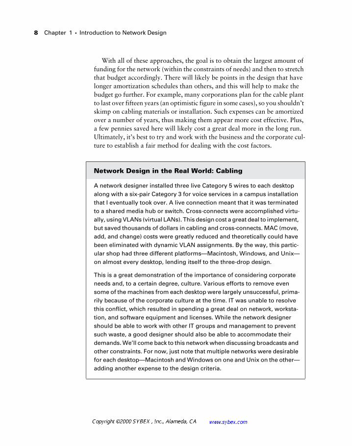
Network Design in the Real World: Cabling
A network designer installed three live Category 5 wires to each desktop along with a six-pair Category 3 for voice services in a campus installation that I eventually took over. A live connection meant that it was terminated to a shared media hub or switch. Cross-connects were accomplished virtu-ally, using VLANs (virtual LANs). This design cost a great deal to implement, but saved thousands of dollars in cabling and cross-connects. MAC (move, add, and change) costs were greatly reduced and theoretically could have been eliminated with dynamic VLAN assignments. By the way, this partic-ular shop had three different platforms—Macintosh, Windows, and Unix—on almost every desktop, lending itself to the three-drop design.
This is a great demonstration of the importance of considering corporate needs and, to a certain degree, culture. Various efforts to remove even some of the machines from each desktop were largely unsuccessful, prima-rily because of the corporate culture at the time. IT was unable to resolve this conflict, which resulted in spending a great deal on network, worksta-tion, and software equipment and licenses. While the network designer should be able to work with other IT groups and management to prevent such waste, a good designer should also be able to accommodate their demands. We’ll come back to this network when discussing broadcasts and other constraints. For now, just note that multiple networks were desirable for each desktop—Macintosh and Windows on one and Unix on the other—adding another expense to the design criteria.
Network Design Goals
9
The Bottom Line
It helps to have a bit of accounting experience or at least a relationship with the Accounting department when calculating network design costs. Forgoing options such as leasing, there are a couple of ways to assess the cost of a net-work design.
Basically, costs will appear in two general categories. The first is initial costs—those costs that appear once, typically at the beginning of the pur-chasing process. For example, the acquisition of a router or switch would likely be an initial cost. Initial costs are important for a number of reasons. However, these costs can be a bit misleading. Larger corporations will incor-porate an amortization on equipment based on the projected lifespan of the device. Thus, a router may actually be entered as a cost over 30 months instead of just one month. This variance can greatly impact the budgets of both the network and the corporation. It’s important to consult with the Accounting group in your organization so that you understand how such costs are treated.
The second category is recurring costs. These costs frequently relate to cir-cuits and maintenance contracts and are typically paid on a monthly or annual basis. These costs can frequently overshadow the initial costs—a $100,000 router is cheap compared to a monthly $50,000 telecommunica-tions bill. Consider that the monthly cost for a $100,000 router is only 18 percent of the cost for a $50,000-a-month circuit after the first year—and that router will have residual value for years beyond.
A significant amount of this material is written in the context of large corpora-tions and enterprise-class businesses. In reality, the concepts hold true for even
the smallest companies.
Additional Design Goals
While Cisco typically refers to the three goals of network design, our discus-sion would be incomplete if the list was not augmented. In addition to scal-ability, adaptability, and cost control, designers must be familiar with predictability, ease of implementation, manageability, and troubleshooting. These goals integrate well with the three-tier model and will be presented in greater detail in the section, “The Three-Tier (Hierarchical) Network Model,” later in this chapter.
10
Chapter 1 �
Introduction to Network Design
Scalability refers to the ability to add additional nodes and bandwidth to the network, and its characteristics typically interrelate with those of pre-dictability. Predictable networks provide the administrator with a clear traf-fic flow for data and, combined with baselining and monitoring, solid capacity-planning information.
A well-designed network is easily implemented. This characteristic also applies to modular designs, but it does not have to. Implementations typi-cally work best when the developer draws upon prior experience and intro-duces the design in phases. Prior to deploying any new design, the developer should test it in a lab or discuss the installation with others in the field. The adage “Why reinvent the wheel?” is particularly valuable here.
The last network design goal encompasses the recurrent demand for diag-nostics. Unfortunately, even the best designs fail, and sometimes these fail-ures are the result of the design itself. A good design should focus on solid documentation and be as straightforward as possible. For example, a design that uses network address translation (NAT) when it is not required would likely be more difficult to fix in a crisis than one without NAT. Designers should refrain from adding features just because they are available and focus on simplicity of design.
Troubleshooting capabilities can be enhanced by placing monitoring tools in the network. Protocol analyzers and remote monitoring (RMON) probes should be available for rapid dispatch if permanent installations are not an option at critical points in the network, including the core and distri-bution layers. This chapter will later define the core and distribution layers, in addition to the hierarchical model. For now, simply consider the core and distribution layers as the backbone of the network.
Network Design Models
A
t this point, most readers preparing for the CID examination are undoubtedly well versed in the OSI (Open Systems Interconnection) model for network protocols.
If you need additional information regarding the OSI model and its relation-ship to the networking protocols, please consult one of the many texts on the
subject, including the Sybex Network Press publications.
The Flat Network Model
11
This model (the OSI model) explains the functions and relationships of the individual protocols. Similarly, a number of other network design mod-els have been established. Most of these models now focus on a single three-tier methodology. This approach preserves many of the criteria necessary for effective network design and will be presented later in this chapter.
Recall that the OSI model provides benefits in troubleshooting because each layer of the model serves a specific function. For example, the network layer, Layer 3, is charged with logical routing functions. The transport layer, Layer 4, is atop Layer 3 and provides additional services. In the TCP/IP world, Layer 3 is served by IP, and Layer 4 is served by TCP (Transmission Control Protocol) or UDP (User Datagram Protocol).
As a humorous aside, some network designers have added two additional lay-ers to the OSI model—Layer 8, which refers to the political layer, and Layer 9, which represents the financial one. These layers are particularly appropriate
in the context of this chapter.
In the same manner, the network design models provide an overview of the function and abilities of each theoretical network design. The most com-mon large network design, the three-tier approach, further defines functions for each tier. To move from one tier to another, packets should traverse the intermediate tier. Note that in this model the definitions are nowhere near as precise as they are in the OSI model, but the model should be adhered to as closely as possible.
This section will first present some of the alternatives to the OSI model and end with a detailed examination of the three-tier model. The caveats and guidelines for the three-tier approach will be examined in more detail than the other approaches, but readers and designers should consider the positive and negative impacts of each design.
The Flat Network Model
T
he flat network may assume many forms, and it is likely that most readers are very comfortable with this design. In fact, most networks develop from this model.
12
Chapter 1 �
Introduction to Network Design
A flat network contains no routers or Layer 3 awareness (Layer 3 of the OSI model). The network is one large broadcast domain. This does not pre-clude the incorporation of switches or bridges to isolate the collision domain boundaries and, depending upon the protocols in use, it could support up to a few hundred stations. Unfortunately though, this design rarely scales to support the demands of most networks in terms of users, flexibility, and security.
Performance may be only one concern. Typically, the need for access lists (ACLs) and other benefits at Layer 3 in the OSI model will require the incor-poration of routers. The flat network model fails to address many of the important factors in network design—the most significant of which is scal-ability. Consider the impact of a single network interface card (NIC) sending a broadcast onto the network. At Layer 2, this broadcast would reach all sta-tions. Should the NIC experience a fault where it continued to send broad-casts as fast as possible, the entire network would fail.
The Star Network Model
T
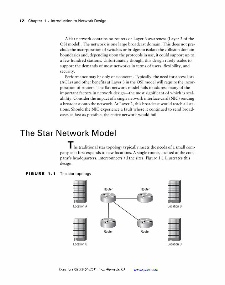
he traditional star topology typically meets the needs of a small com-pany as it first expands to new locations. A single router, located at the com-pany’s headquarters, interconnects all the sites. Figure 1.1 illustrates this design.
F I G U R E 1 . 1
The star topology
Location A Location B
Location C Location D
Router Router
Router Router
The Ring Network Model
13
The following list encompasses both the positive and negative aspects of such a topology, but the negative aspects should be somewhat obvious:
�
Low scalability
�
Single point of failure
�
Low cost
�
Easy setup and administration
Star topologies are experiencing a resurgence with the deployment of pri-vate remote networks, including Digital Subscriber Line (DSL) and Frame Relay solutions. While the entire network will likely mesh into another model, the remote portion of the network will use the star topology. Note that the star topology is also called the hub-and-spoke model.
The Ring Network Model
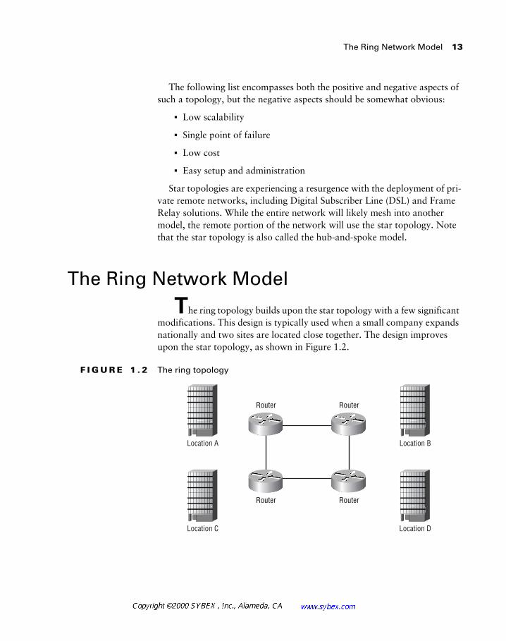
T
he ring topology builds upon the star topology with a few significant modifications. This design is typically used when a small company expands nationally and two sites are located close together. The design improves upon the star topology, as shown in Figure 1.2.
F I G U R E 1 . 2
The ring topology
Location A Location B
Location C Location D
Router Router
Router Router
14
Chapter 1 �
Introduction to Network Design
As you can see, the ring design eliminates one of the main negative aspects of the star topology. In the ring model, a single circuit failure will not dis-connect any location from the enterprise network. However, the ring topol-ogy fails to address these other considerations:
�
Low scalability
�
No single point of failure
�
Higher cost
�
Complex setup and configuration
�
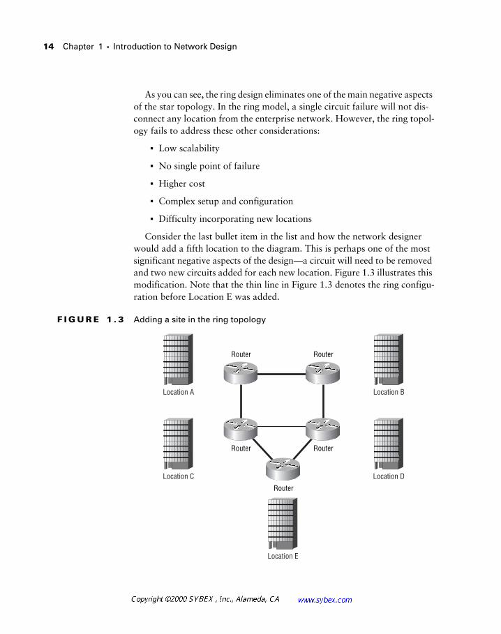
Difficulty incorporating new locations
Consider the last bullet item in the list and how the network designer would add a fifth location to the diagram. This is perhaps one of the most significant negative aspects of the design—a circuit will need to be removed and two new circuits added for each new location. Figure 1.3 illustrates this modification. Note that the thin line in Figure 1.3 denotes the ring configu-ration before Location E was added.
F I G U R E 1 . 3
Adding a site in the ring topology
Location A Location B
Location C Location D
Location E
Router Router
Router Router
Router
The Mesh Network Model
15
While the ring topology addresses the redundancy portion of the network design criteria, it fails to do so in an efficient manner. Therefore, its use is not recommended.
The Mesh Network Model
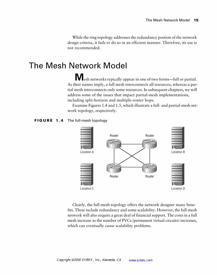
M
esh networks typically appear in one of two forms—full or partial. As their names imply, a full mesh interconnects all resources, whereas a par-tial mesh interconnects only some resources. In subsequent chapters, we will address some of the issues that impact partial-mesh implementations, including split-horizon and multiple-router hops.
Examine Figures 1.4 and 1.5, which illustrate a full- and partial-mesh net-work topology, respectively.
F I G U R E 1 . 4
The full-mesh topology
Clearly, the full-mesh topology offers the network designer many bene-fits. These include redundancy and some scalability. However, the full-mesh network will also require a great deal of financial support. The costs in a full mesh increase as the number of PVCs (permanent virtual circuits) increases, which can eventually cause scalability problems.
Location A Location B
Location C Location D
Router Router
Router Router
16
Chapter 1 �
Introduction to Network Design
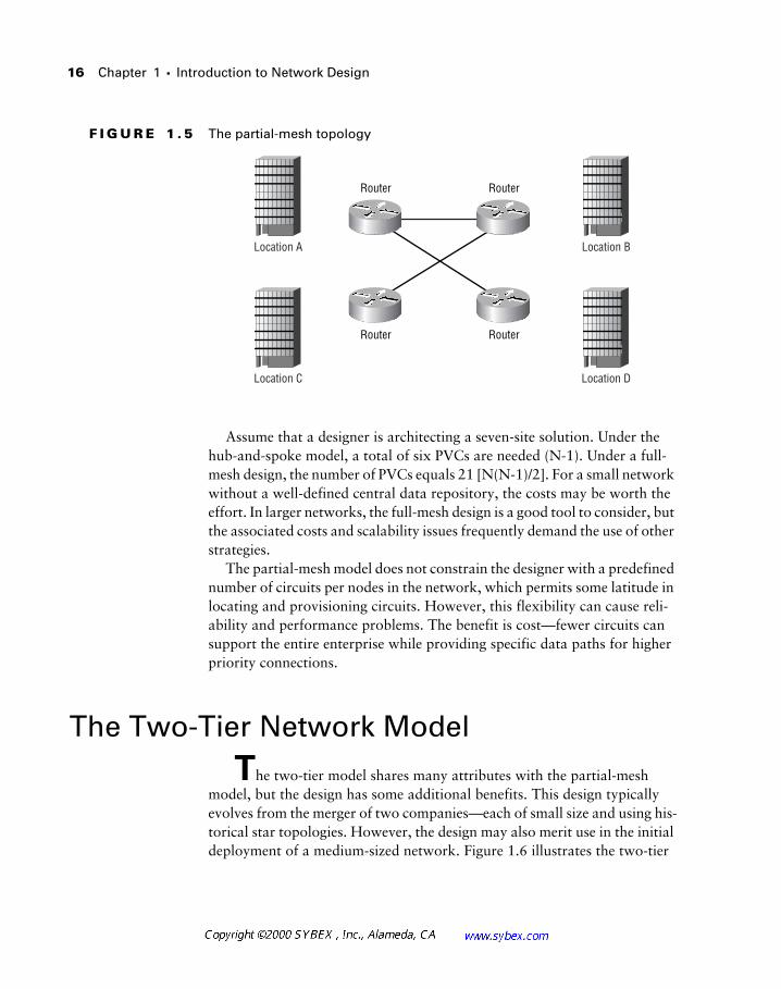
F I G U R E 1 . 5
The partial-mesh topology
Assume that a designer is architecting a seven-site solution. Under the hub-and-spoke model, a total of six PVCs are needed (N-1). Under a full-mesh design, the number of PVCs equals 21 [N(N-1)/2]. For a small network without a well-defined central data repository, the costs may be worth the effort. In larger networks, the full-mesh design is a good tool to consider, but the associated costs and scalability issues frequently demand the use of other strategies.
The partial-mesh model does not constrain the designer with a predefined number of circuits per nodes in the network, which permits some latitude in locating and provisioning circuits. However, this flexibility can cause reli-ability and performance problems. The benefit is cost—fewer circuits can support the entire enterprise while providing specific data paths for higher priority connections.
The Two-Tier Network Model
T
he two-tier model shares many attributes with the partial-mesh model, but the design has some additional benefits. This design typically evolves from the merger of two companies—each of small size and using his-torical star topologies. However, the design may also merit use in the initial deployment of a medium-sized network. Figure 1.6 illustrates the two-tier
Location A Location B
Location C Location D
Router Router
Router Router
The Three-Tier (Hierarchical) Network Model 17
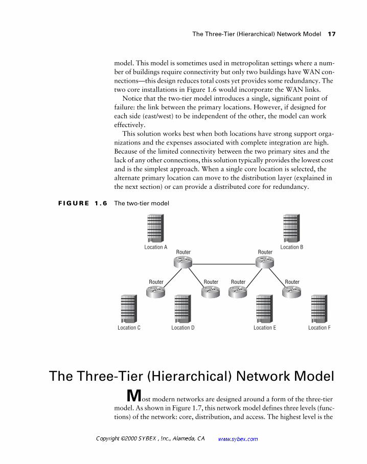
model. This model is sometimes used in metropolitan settings where a num-ber of buildings require connectivity but only two buildings have WAN con-nections—this design reduces total costs yet provides some redundancy. The two core installations in Figure 1.6 would incorporate the WAN links.
Notice that the two-tier model introduces a single, significant point of failure: the link between the primary locations. However, if designed for each side (east/west) to be independent of the other, the model can work effectively.
This solution works best when both locations have strong support orga-nizations and the expenses associated with complete integration are high. Because of the limited connectivity between the two primary sites and the lack of any other connections, this solution typically provides the lowest cost and is the simplest approach. When a single core location is selected, the alternate primary location can move to the distribution layer (explained in the next section) or can provide a distributed core for redundancy.
F I G U R E 1 . 6 The two-tier model
The Three-Tier (Hierarchical) Network Model
Most modern networks are designed around a form of the three-tier model. As shown in Figure 1.7, this network model defines three levels (func-tions) of the network: core, distribution, and access. The highest level is the
Location C
Location A
Location D Location E
Location B
Location F
Router Router
Router Router
RouterRouter
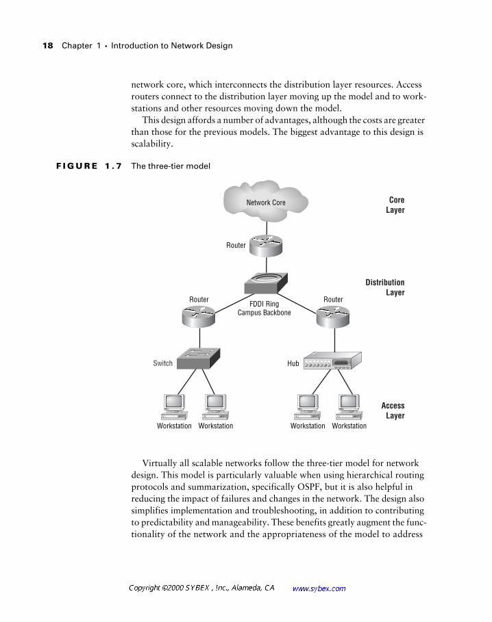
18 Chapter 1 � Introduction to Network Design
network core, which interconnects the distribution layer resources. Access routers connect to the distribution layer moving up the model and to work-stations and other resources moving down the model.
This design affords a number of advantages, although the costs are greater than those for the previous models. The biggest advantage to this design is scalability.
F I G U R E 1 . 7 The three-tier model
Virtually all scalable networks follow the three-tier model for network design. This model is particularly valuable when using hierarchical routing protocols and summarization, specifically OSPF, but it is also helpful in reducing the impact of failures and changes in the network. The design also simplifies implementation and troubleshooting, in addition to contributing to predictability and manageability. These benefits greatly augment the func-tionality of the network and the appropriateness of the model to address
Switch
Network Core
FDDI RingCampus Backbone
Workstation Workstation Workstation Workstation
Hub
AccessLayer
CoreLayer
DistributionLayer
Router
Router Router
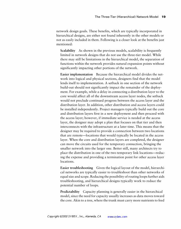
The Three-Tier (Hierarchical) Network Model 19
network design goals. These benefits, which are typically incorporated in hierarchical designs, are either not found inherently in the other models or not as easily included in them. Following is a closer look at the benefits just mentioned:
Scalability As shown in the previous models, scalability is frequently limited in network designs that do not use the three-tier model. While there may still be limitations in the hierarchical model, the separation of functions within the network provides natural expansion points without significantly impacting other portions of the network.
Easier implementation Because the hierarchical model divides the net-work into logical and physical sections, designers find that the model lends itself to implementation. A setback in one section of the network build-out should not significantly impact the remainder of the deploy-ment. For example, while a delay in connecting a distribution layer to the core would affect all of the downstream access layer nodes, the setback would not preclude continued progress between the access layer and the distribution layer. In addition, other distribution and access layers could be installed independently. Project managers typically build out the core and distribution layers first in a new deployment and then proceed with the access layer; however, if immediate service is needed at the access layer, the designer may adopt a plan that focuses on that tier and then interconnects with the infrastructure at a later time. This means that the designer may be required to provide a connection between two locations that are remote—locations that would typically be located in the access layer. When the core and distribution layers are completed, the designer can move the circuits used for the temporary connection, bringing the smaller network into the larger one. Better still, many architects try to place the distribution in one of the two temporary link locations—reduc-ing the expense and providing a termination point for other access layer locations.
Easier troubleshooting Given the logical layout of the model, hierarchi-cal networks are typically easier to troubleshoot than other networks of equal size and scope. Reducing the possibility of routing loops further aids troubleshooting, and hierarchical designs typically work to reduce the potential number of loops.
Predictability Capacity planning is generally easier in the hierarchical model, since the need for capacity usually increases as data moves toward the core. Akin to a tree, where the trunk must carry more nutrients to feed
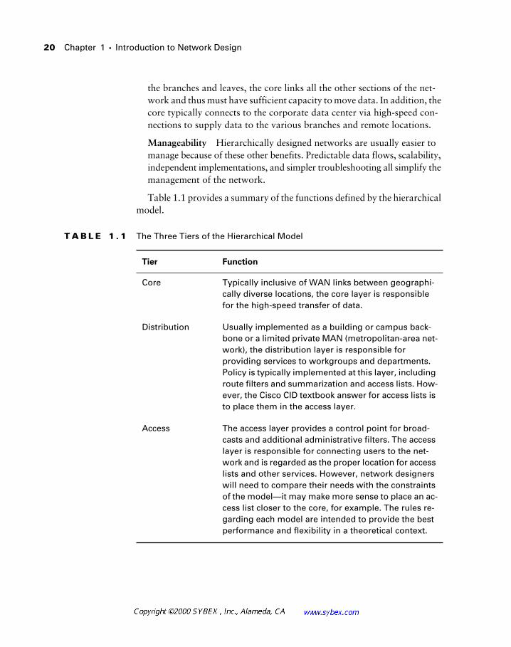
20 Chapter 1 � Introduction to Network Design
the branches and leaves, the core links all the other sections of the net-work and thus must have sufficient capacity to move data. In addition, the core typically connects to the corporate data center via high-speed con-nections to supply data to the various branches and remote locations.
Manageability Hierarchically designed networks are usually easier to manage because of these other benefits. Predictable data flows, scalability, independent implementations, and simpler troubleshooting all simplify the management of the network.
Table 1.1 provides a summary of the functions defined by the hierarchical model.
T A B L E 1 . 1 The Three Tiers of the Hierarchical Model
Tier Function
Core Typically inclusive of WAN links between geographi-cally diverse locations, the core layer is responsible for the high-speed transfer of data.
Distribution Usually implemented as a building or campus back-bone or a limited private MAN (metropolitan-area net-work), the distribution layer is responsible for providing services to workgroups and departments. Policy is typically implemented at this layer, including route filters and summarization and access lists. How-ever, the Cisco CID textbook answer for access lists is to place them in the access layer.
Access The access layer provides a control point for broad-casts and additional administrative filters. The access layer is responsible for connecting users to the net-work and is regarded as the proper location for access lists and other services. However, network designers will need to compare their needs with the constraints of the model—it may make more sense to place an ac-cess list closer to the core, for example. The rules re-garding each model are intended to provide the best performance and flexibility in a theoretical context.
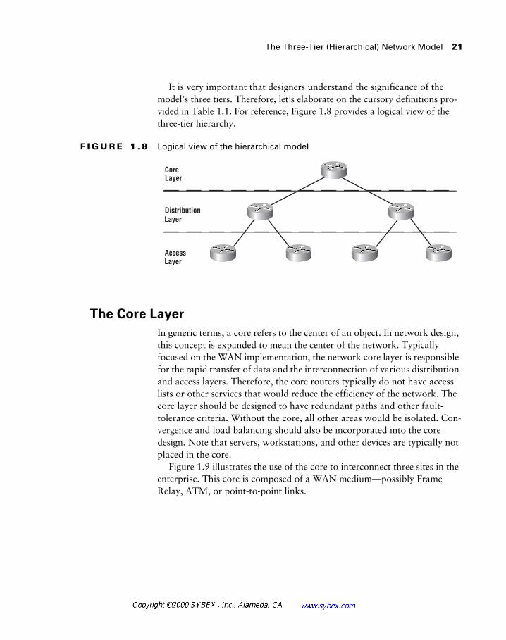
The Three-Tier (Hierarchical) Network Model
21
It is very important that designers understand the significance of the model’s three tiers. Therefore, let’s elaborate on the cursory definitions pro-vided in Table 1.1. For reference, Figure 1.8 provides a logical view of the three-tier hierarchy.
F I G U R E 1 . 8
Logical view of the hierarchical model
The Core Layer
In generic terms, a core refers to the center of an object. In network design, this concept is expanded to mean the center of the network. Typically focused on the WAN implementation, the network core layer is responsible for the rapid transfer of data and the interconnection of various distribution and access layers. Therefore, the core routers typically do not have access lists or other services that would reduce the efficiency of the network. The core layer should be designed to have redundant paths and other fault-tolerance criteria. Without the core, all other areas would be isolated. Con-vergence and load balancing should also be incorporated into the core design. Note that servers, workstations, and other devices are typically not placed in the core.
Figure 1.9 illustrates the use of the core to interconnect three sites in the enterprise. This core is composed of a WAN medium—possibly Frame Relay, ATM, or point-to-point links.
Core
Access
DistributionLayer
Layer
Layer
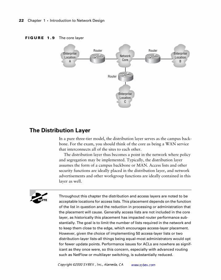
22 Chapter 1 � Introduction to Network Design
F I G U R E 1 . 9 The core layer
The Distribution Layer
In a pure three-tier model, the distribution layer serves as the campus back-bone. For the exam, you should think of the core as being a WAN service that interconnects all of the sites to each other.
The distribution layer thus becomes a point in the network where policy and segregation may be implemented. Typically, the distribution layer assumes the form of a campus backbone or MAN. Access lists and other security functions are ideally placed in the distribution layer, and network advertisements and other workgroup functions are ideally contained in this layer as well.
Throughout this chapter the distribution and access layers are noted to be acceptable locations for access lists. This placement depends on the function of the list in question and the reduction in processing or administration that the placement will cause. Generally access lists are not included in the core layer, as historically this placement has impacted router performance sub-stantially. The goal is to limit the number of lists required in the network and to keep them close to the edge, which encourages access-layer placement. However, given the choice of implementing 50 access-layer lists or two distribution-layer lists-all things being equal-most administrators would opt for fewer update points. Performance issues for ACLs are nowhere as signif-icant as they once were, so this concern, especially with advanced routing such as NetFlow or multilayer switching, is substantially reduced.
Router Router
Router
NetworkCore
EnterpriseLocation
C
EnterpriseLocation
B
EnterpriseLocation
A
The Three-Tier (Hierarchical) Network Model 23
For the purposes of the CID exam, the proper placement of access lists is the access layer. For production networks, it is acceptable, and sometimes desir-able, to place them in the distribution layer. For the CCNA/CCDA small-to-medium business examination, the proper placement of the access lists is always the distribution layer, which is different than the CID recommendation.
For example, it would be appropriate for a SAP (Service Advertising Pro-tocol) filter to block Novell announcements of printer services at the distri-bution layer because it is unlikely that users outside of the distribution layer would need access to them. The textbook answer, however, is to place access lists at the access layer of the model.
Route summarization and the logical organization of resources are also well aligned with the distribution layer. A strong design would encompass some logical method of summarizing the routes in the distribution layer. Fig-ure 1.10 displays the IP (Internet Protocol) addressing and DNS (Domain Name Service) names for two distribution layers attached to the core. Note how 10.11.0.0/16 and 10.12.0.0/16 are divided at each router. Thus, routing tables in the core need only focus on one route, as opposed to the numerous routes that might be incorporated into the distribution area. In the same manner, the DNS subdomains are aligned with each distribution layer, which, along with IP addressing standards, will greatly augment the effi-ciency of the troubleshooting process. Troubleshooting is simplified when administrators can quickly identify the location and scope of a network out-age—a benefit of addressing standards. In addition, route summarization, a concept presented in Chapter 4, can help avoid recalculations of the routing table that might lead to problems on lower-end routers.
The final advantage of using this distribution layer design in the three-tier model is that it will greatly simplify OSPF configurations. The network core becomes a natural area 0, while each distribution router becomes an area border router between area 0 and other areas.
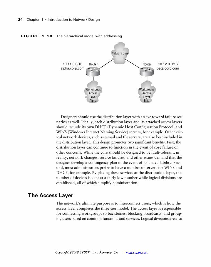
24 Chapter 1 � Introduction to Network Design
F I G U R E 1 . 1 0 The hierarchical model with addressing
Designers should use the distribution layer with an eye toward failure sce-narios as well. Ideally, each distribution layer and its attached access layers should include its own DHCP (Dynamic Host Configuration Protocol) and WINS (Windows Internet Naming Service) servers, for example. Other crit-ical network devices, such as e-mail and file servers, are also best included in the distribution layer. This design promotes two significant benefits. First, the distribution layer can continue to function in the event of core failure or other concerns. While the core should be designed to be fault-tolerant, in reality, network changes, service failures, and other issues demand that the designer develop a contingency plan in the event of its unavailability. Sec-ond, most administrators prefer to have a number of servers for WINS and DHCP, for example. By placing these services at the distribution layer, the number of devices is kept at a fairly low number while logical divisions are established, all of which simplify administration.
The Access Layer
The network’s ultimate purpose is to interconnect users, which is how the access layer completes the three-tier model. The access layer is responsible for connecting workgroups to backbones, blocking broadcasts, and group-ing users based on common functions and services. Logical divisions are also
10.11.0.0/16alpha.corp.com
10.12.0.0/16beta.corp.com
Router Router
Network Core
WorkgroupsAccessLayerAlpha
WorkgroupsAccessLayerBeta
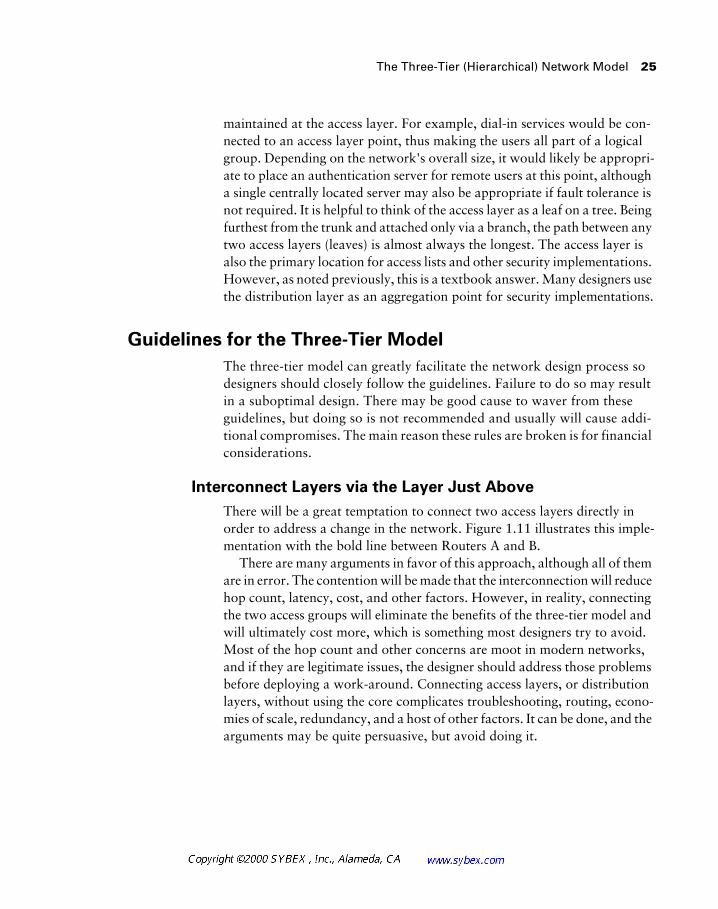
The Three-Tier (Hierarchical) Network Model 25
maintained at the access layer. For example, dial-in services would be con-nected to an access layer point, thus making the users all part of a logical group. Depending on the network's overall size, it would likely be appropri-ate to place an authentication server for remote users at this point, although a single centrally located server may also be appropriate if fault tolerance is not required. It is helpful to think of the access layer as a leaf on a tree. Being furthest from the trunk and attached only via a branch, the path between any two access layers (leaves) is almost always the longest. The access layer is also the primary location for access lists and other security implementations. However, as noted previously, this is a textbook answer. Many designers use the distribution layer as an aggregation point for security implementations.
Guidelines for the Three-Tier Model
The three-tier model can greatly facilitate the network design process so designers should closely follow the guidelines. Failure to do so may result in a suboptimal design. There may be good cause to waver from these guidelines, but doing so is not recommended and usually will cause addi-tional compromises. The main reason these rules are broken is for financial considerations.
Interconnect Layers via the Layer Just Above
There will be a great temptation to connect two access layers directly in order to address a change in the network. Figure 1.11 illustrates this imple-mentation with the bold line between Routers A and B.
There are many arguments in favor of this approach, although all of them are in error. The contention will be made that the interconnection will reduce hop count, latency, cost, and other factors. However, in reality, connecting the two access groups will eliminate the benefits of the three-tier model and will ultimately cost more, which is something most designers try to avoid. Most of the hop count and other concerns are moot in modern networks, and if they are legitimate issues, the designer should address those problems before deploying a work-around. Connecting access layers, or distribution layers, without using the core complicates troubleshooting, routing, econo-mies of scale, redundancy, and a host of other factors. It can be done, and the arguments may be quite persuasive, but avoid doing it.
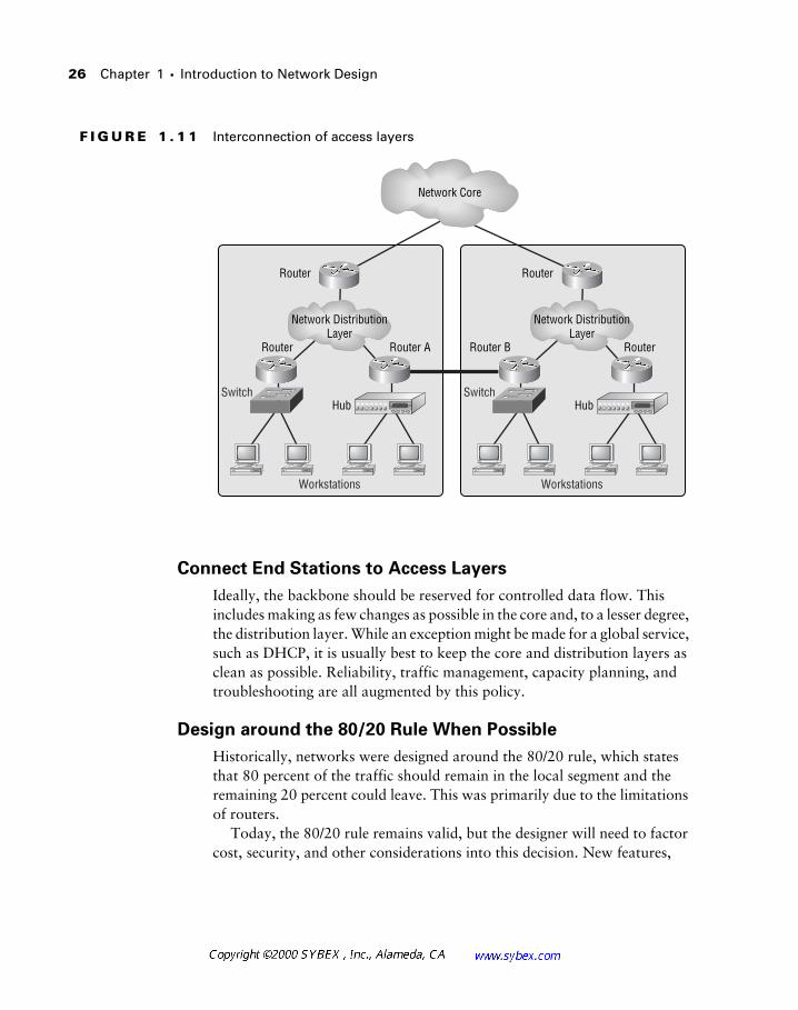
26 Chapter 1 � Introduction to Network Design
F I G U R E 1 . 1 1 Interconnection of access layers
Connect End Stations to Access Layers
Ideally, the backbone should be reserved for controlled data flow. This includes making as few changes as possible in the core and, to a lesser degree, the distribution layer. While an exception might be made for a global service, such as DHCP, it is usually best to keep the core and distribution layers as clean as possible. Reliability, traffic management, capacity planning, and troubleshooting are all augmented by this policy.
Design around the 80/20 Rule When Possible
Historically, networks were designed around the 80/20 rule, which states that 80 percent of the traffic should remain in the local segment and the remaining 20 percent could leave. This was primarily due to the limitations of routers.
Today, the 80/20 rule remains valid, but the designer will need to factor cost, security, and other considerations into this decision. New features,
Switch
Network DistributionLayer
Hub
Workstations
Switch
Network DistributionLayer
Hub
Workstations
Router
Router Router A
Router
Router B Router
Network Core
The Three-Tier (Hierarchical) Network Model 27
including route once/switch many technologies and server farms have altered the 80/20 rule in many designs. The Internet and other remote services have also impacted these criteria. While it is preferable to keep traffic locally bound, in modern networks it is much more difficult to do so, and the ben-efits are not as great as before.
While the 80/20 rule does remain a good guideline, it is important to note that most modern networks are confronted with traffic models that follow the corollary of the 80/20 rule. The 20/80 rule acknowledges that 80 percent of the traffic is off the local subnet in most modern networks. This is the result of centralized server farms, database servers, and the Internet. Design-ers should keep this fact in mind when designing the network—some instal-lations are already bordering on a 5/95 ratio. It is conceivable that less than five percent of the traffic will remain on the local subnet in the near term as bandwidth availability increases.
Make Each Layer Represent a Layer 3 Boundary
This is possibly one of the easier guidelines to understand, as routers are included at each layer in the model and these routers divide Layer 3 bound-aries. Therefore, this rule takes on a default status. It also relates to the policy of not linking various layers without using the layer just above in that switches (Layer 2 devices) should not be used to interconnect access layer
Network Design in the Real World: Outsourcing
In 1998 and 1999, the networking industry saw an explosion of outsourcing efforts to move responsibility for the data center away from the enterprise. The intent was to reduce costs and allow the organization to focus on their core business. While some of these efforts were less than successful, there is little doubt that contracting and outsourcing will remain acceptable strat-egies for many companies.
The need for high-speed connections is one consequence of off-site data cen-ters. A number of companies place their file servers in a remote, outsourced location, moving all of their data away from the user community. It is likely that this trend, should it continue, will take data off not only the user subnet (the origin of the 80/20 rule), but the local campus network as well.
28 Chapter 1 � Introduction to Network Design
groups. Later in this text the issues of spanning tree and Layer 3 designs will be presented—they relate well to this policy.
Note that this guideline also incorporates a separation of the broadcast and collision domains. Network design model layers cannot be isolated by only collision domains—a function of Layer 2 devices, including bridges and switches. The layers must also be isolated via routers, which define the bor-ders of the broadcast domain.
Implement Features at the Appropriate Layer
This guideline is one of the most difficult to enforce, yet it is one of the most important. Included in this policy is the recommendation that access lists remain outside of the core layer. While Cisco has greatly improved the per-formance of their router products, access lists and other services still impose a substantial burden on resources (depending on router type and features). By keeping these functions at a deeper layer of the model, the designer should be able to maintain performance for the majority of packets. Each design will require some interpretation of this guideline—there clearly may be excep-tions where a feature must be deployed at a specific point in the network.
Network Design Issues
All good network designs will address at least one of the following questions. Excellent designs will answer all of them:
� What problem are we trying to solve?
� What future needs do we anticipate?
� What is the projected lifespan of this network?
What Problem?
New networks are typically deployed to solve a business problem. Since there is no legacy network, there are few issues regarding the existing infra-structure to address. Existing networks confronted by a potential upgrade are typically designed to resolve at least one of the problems discussed below, under “Considerations of Network Design.”
Considerations of Network Design 29
Future Needs?
It is unlikely that anyone with the ability to accurately predict the future would use such ability to design networks. Ignorance is a likely enemy of efforts to add longevity to the network design. An assessment of future needs will incorporate a number of areas that will help augment the lifespan of the network, but success is frequently found in “gut feelings” and overspending.
Network Lifespan?
Many would classify this topic as part of the future needs assessment; how-ever, it should be viewed as a separate component. The lifespan of the net-work should also not be viewed in terms of a single span of time. For example, copper and fiber installations should be planned with at least a 10-year horizon, whereas network core devices that remain static for more than 36 months are rare. Given these variations, it is important to balance the costs of each network component with the likelihood that it will be replaced quickly. Building in expandability and upgradability will affect the lifespan of a network installed today. Designers should always consider how they might expand their designs to accommodate additional users or services before committing to a strategy.
Considerations of Network Design
The network design considerations addressed in this section are the solutions to the network design issues addressed earlier. For example, the first network design consideration below addresses excessive broadcasts. The designer will need to understand the concept of broadcasts in the net-work, how they are impacting the existing network, how they may increase in the future, and how broadcasts may be dealt with in the lifespan of the network.
Excessive Broadcasts
Recall that broadcasts are used in networking to dispatch a packet to all sta-tions on the network. This may be in the form of an Address Resolution Pro-tocol (ARP) query or a NetBIOS name query, for example. All stations will
30 Chapter 1 � Introduction to Network Design
listen and accept broadcast packets for processing by an upper-layer pro-cess—the broadcast itself is a Layer 2 process.
While the broadcast packet is no larger than any other packet on the media, it is received by all stations. This results in every station halting the local process to address the packet that has been forwarded from the net-work interface card. This added processing is very inefficient and, for the majority of stations, unnecessary.
A general network design guideline says that 100 broadcasts per second will reduce the available CPU on a Pentium 90 processor by two percent. Note that this figure does not compare the percentage of broadcasts on the network to user data (typically unicast). While most modern networks are now using much more powerful processors and larger amounts of band-width per workstation, broadcasts are still an area warranting control by the network designer and administrator.
There are two methods for controlling broadcasts in the network. Routers control the broadcast domain. Thus, a router could be used to divide a single network into two smaller ones. This would theoretically reduce the number of broadcasts per segment by 50 percent. This technique would also affect bandwidth and media contention, so it might be the correct solution. How-ever, it’s now much easier to use a router to reduce broadcasts. In reality, the total number of broadcasts will almost always increase when using two net-works instead of one. This is due to the nature of the upper-layer protocols. For example, a single network could use a single Service Advertising Proto-col (SAP) packet (Novell), whereas a dual network installation will require at least two. The number of broadcasts per network will decrease, but not by 50 percent.
Another method for controlling broadcasts is to remove them at the source—typically servers and, to a lesser extent, workstations. This is one aspect of network design that greatly benefits from the designer having a detailed knowledge of both protocols and operating systems. For example, Apple computer has offered an IP-based solution for its traditional Apple-Talk networks for a long time. Implementation of this service would greatly reduce the number of broadcasts in the network for a number of reasons, including the elimination of an entire protocol and AppleTalk’s intensive use of broadcasts. Assuming that most workstations are also running IP for Internet connectivity, this design could easily be incorporated into the net-work. Removing AppleTalk provides two benefits—a reduction in back-ground broadcasts compared with IP and in the amount of overhead demanded by the network.
Considerations of Network Design 31
Contention for the Media
Media contention is frequently associated with 10Mbps Ethernet, where a large number of stations are waiting for access to the physical layer and a large number of collisions are likely to occur. However, media contention can also occur in FDDI and Token Ring. While both of these technologies negate the possibility of collision, each station must wait for receipt of the token before transmitting. This can cause significant delays.
Historically, access to the media was controlled by installing additional router ports and hubs. Installing new routers may result in network-wide IP readdressing, which may have a large up-front cost factor. While installing these routers reduced the number of stations on the segment, it did not elim-inate contention issues; rather, it reduced the impact and frequency of them. With the advent of switching technology in the network, designers were offered the opportunity to virtually eliminate contention at a low cost. Dis-counting buffering issues and other advanced considerations, a full-duplex connection presents no contention points. This is a marked improvement that may be implemented with no change to the user workstation (with the possible exception of a full-duplex-capable network card). Designers should consider the use of switching technologies to resolve media-contention issues.
Security
Security is one of the overlooked components of network design. Typically, the security procedures and equipment are added to the network well into the implementation phase. This usually results in a less-secure configuration that demands compromises. For example, access lists are one component of net-work security. Assuming a hierarchical design, if the network designers were to use bit boundaries to define security domains, a single access-list wildcard mask could be used in different areas of the network. In addition, extranet (non-internal) connections could be placed in a secure, centralized location, freeing greater bandwidth for the rest of the enterprise. This design contrasts with installations where these connections are distributed throughout the network. While centralization may lead to more significant outages, it is often easier to administer resources in a protected, central location close to the support organization.
32 Chapter 1 � Introduction to Network Design
Consider for a moment a fairly benign network design decision. A com-pany elects to deploy an ATM WAN for a new network upgrade. The net-work requires some security, because the data is privileged and involves financial information. Rather than isolating extranet connections, the com-pany decides to place these less-secure links on the same physical interface as their internal connections. While this setup can work, think about the limi-tations that such a design would impose on security. The designer would be unable to restrict the PVC before the circuit entered the core router, thus making the only line of defense a subinterface access list. Denial-of-service attacks and other intrusion techniques would be much more likely than if the extranet PVC were isolated from the enterprise network by a separate router and a firewall.
Having identified security as a design consideration, the designer must evaluate the role of the network in the security model. There is little question that firewalls and bastion hosts (a bastion host is a secure public presence—it may be the firewall itself or a server in the transition area between the pub-lic and private networks, also called a DMZ) are part of the network, but some schools of thought argue that the network, in and of itself, is not a secu-rity device. While there are compelling arguments to support the stance that the network is not a security solution, most designers take a simpler view of security. In practical terms, anything that can protect the data in the net-work—be it a lock on a door, an access list, or the use of fiber instead of cop-per—is part of an overall solution and should be considered in the design of the network.
Some of the tools available to the network architect are:
� Fiber links
� Firewalls
� Access lists
� Bastion hosts
� Encryption
� Authentication, including CHAP (Challenge Handshake Authentica-tion Protocol)
� Accounting
� Secure physical media, including data rooms and cables
� Auditing tools
Considerations of Network Design 33
All available tools should be considered when formulating a design. By including them in the initial phases, appropriate budgetary and technology allocations may be made.
A complete presentation of network security and design considerations for architects is presented in Chapter 11.
Addressing
Addressing issues frequently involve the IP protocol, which uses user-defined addresses. Many networks evolved without regard to the strategic impor-tance of the infrastructure. In addition, corporations occasionally acquire another organization, resulting in the duplication of network addresses even with careful planning. Whatever the cause, readdressing IP addresses is a sig-nificant process in the life of the network. And while DHCP, NAT, and dynamic DNS can reduce the impact, there will likely be a point where some determined effort is necessary.
Subsequent chapters will discuss the art of network readdressing; how-ever, there are a few points that should be presented here. First, plan for con-nectivity to other companies and the Internet. Second, consider the impact of readdressing on the corporation’s servers and workstations and have a plan in mind on how to deploy any remedial effort. Third, know the limitations of the various tools that would be used in readdressing, including the fact that NAT cannot cope with NetBIOS traffic—an important function of the Windows and OS/2 operating systems. Chapter 7 presents the NetBIOS pro-tocol in detail. In addition, designers will need to consider the use of RFC 1918 addresses—a collection of addresses specifically reserved from appear-ing on the Internet. Finally, consider the impact of the classful network address and the routing protocols that you might need.
Don’t be concerned if some of the issues presented here are new. In later chapters they will be presented in greater detail.
Bandwidth
There are two schools of thought regarding bandwidth in network design. The first believes that the network is built to withstand peaks and then some. Historically, this has resulted in throwing bandwidth at poor application
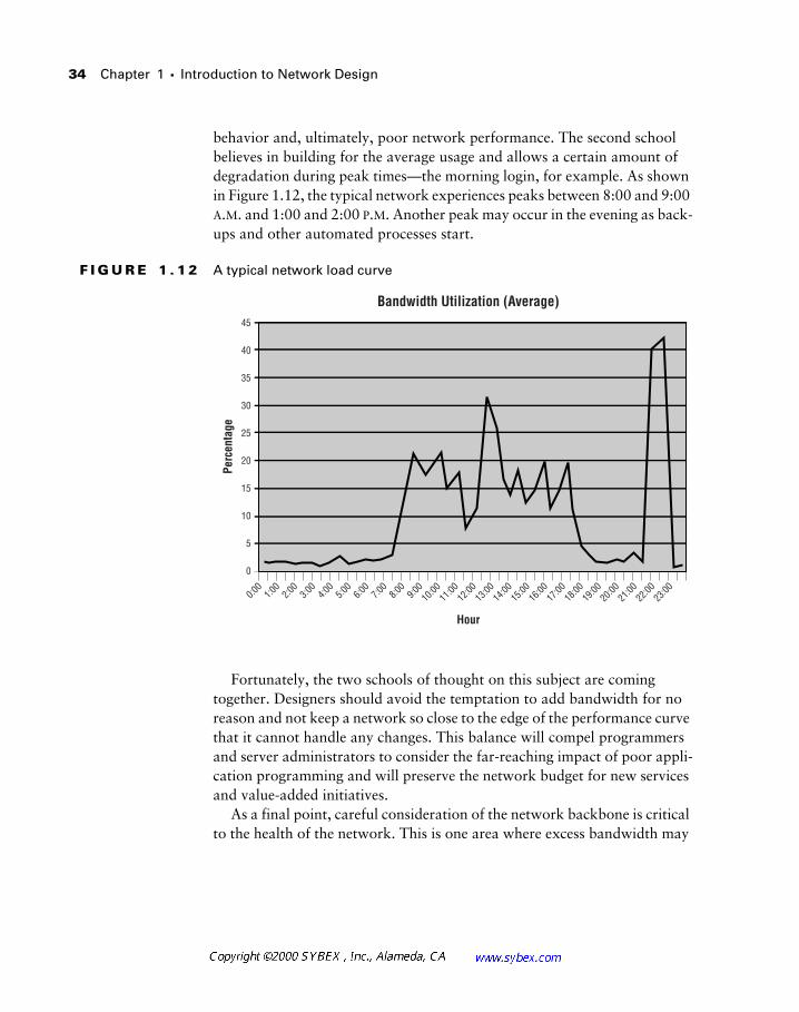
34 Chapter 1 � Introduction to Network Design
behavior and, ultimately, poor network performance. The second school believes in building for the average usage and allows a certain amount of degradation during peak times—the morning login, for example. As shown in Figure 1.12, the typical network experiences peaks between 8:00 and 9:00 A.M. and 1:00 and 2:00 P.M. Another peak may occur in the evening as back-ups and other automated processes start.
F I G U R E 1 . 1 2 A typical network load curve
Fortunately, the two schools of thought on this subject are coming together. Designers should avoid the temptation to add bandwidth for no reason and not keep a network so close to the edge of the performance curve that it cannot handle any changes. This balance will compel programmers and server administrators to consider the far-reaching impact of poor appli-cation programming and will preserve the network budget for new services and value-added initiatives.
As a final point, careful consideration of the network backbone is critical to the health of the network. This is one area where excess bandwidth may
0
0:00
1:00
2:00
3:00
4:00
5:00
6:00
7:00
8:00
9:00
10:00
11:00
12:00
13:00
14:00
15:00
16:00
17:00
18:00
19:00
21:00
23:00
20:00
22:00
5
10
15
20
25
30
35
40
45
Perc
enta
ge
Hour
Bandwidth Utilization (Average)
Considerations of Network Design 35
be the perfect solution, but only if consideration is given to cost and over-head. For example, many companies jumped on the ATM LANE (LAN Emulation) platform for backbone technology in the late 1990s. While a good solution, LANE greatly adds to the cost of the network and the over-head associated with it. Gigabit Ethernet and other technologies may pro-vide better solutions, equal or greater bandwidth, and lower cost. Of course, if voice and other services geared toward ATM are needed, the effort may be warranted.
New Payloads
Networks are frequently called upon to supply services beyond those origi-nally anticipated. Not that long ago, video and voice over data networks (LAN systems) were costly and lacked sufficient business drivers for imple-mentation. As the technology advances, more and more firms are exploring these services.
In addition, there may be enhancements to existing systems that greatly add to the network’s burden. Consider a simple database that contains the names and addresses of a company’s customers. Each record might average 2,000 characters—less than 10,000 bits, including overhead. When the data-base is enhanced to include digital images of the customers and their homes in addition to a transcript of their previous five calls, it is easy to see the potential impact. What was 2,000 characters may exceed 2 million, possibly resulting in millions of bits per transaction. No protocol was added to the network nor were additional users placed in the switch, but the impact would greatly tax even the best designs.
Configuration Simplification
One of the most significant costs in the network results from the move, add, and change (MAC) process. This process refers to the effort involved in installing new users onto the network or changing their installation. The MAC process also includes the relocation of users and their systems.
Various studies have been conducted to measure the true cost of MAC efforts, directly related to both the network costs and the lost productivity of the workers affected. Given that employees may earn $50 an hour on aver-age, a half-day move of even 20 employees will cost $4,000 in lost produc-tivity, not including the impact on non-moved workers. Add the cost of
36 Chapter 1 � Introduction to Network Design
wiring, configuring, installing, and relocating workstations and other sys-tems, and the cost jumps significantly. With the average worker moving 1.1 times per year (according to some surveys from 1997), it is easy to see how this minor cost would quickly impact the finances of the company.
To address these costs, vendors have added features to simplify and accel-erate the MAC process. These may include the use of VLAN/ELAN tech-nology (Virtual LANs/Emulated LANs) and DHCP, for example. DHCP is a dynamic method for assigning IP addresses to workstations. The designer should consider these features in any new design and use any cost savings to help offset the initial costs against the recurring costs.
Protocol Scalability
Protocol scalability refers to a protocol’s ability to service increasingly larger numbers of nodes and users. As an example, IP is capable of servicing mil-lions of users with careful planning and design. AppleTalk, in contrast, does not scale well due to the chatty nature of the protocol and its use of broad-casts and announcements to inform all devices in the network about all other resources. IPX/Novell and NetBIOS share these limitations. Keep in mind that scalable protocols are frequently routable—they contain a Layer 3 address that routers can use for logical grouping. This address further groups and segments systems for efficiency.
Business Relationships
If there is one aspect of network design that overshadows all others, it would have to be the integration of the business objective with the implementation.
Consider these scenarios for a moment. A network is designed to carry data—data that is increasingly critical to a business. In addition, this busi-ness funds the network equipment and implementation. A similar scenario may involve a small home network. In preparing for a Cisco examination, an administrator creates a small lab with the objective of passing the test. Or the home user wishes to establish a LAN for sharing a printer and some files. On a grander scale, an international corporation uses networks to exchange data with business partners and workgroups alike. In each scenario, each of these groups is choosing to spend money on a network in the hope that the initial costs will be offset by the improvements in productivity or increased sales. Business types refer to this as “opportunity cost,” and network designers should use this term as well.
Considerations of Network Design 37
There are really two types of business relationships that involve network designers. The first presents itself in the form of the requester. The requester may be the administrator—perhaps a technical benefit has been identified with respect to changing routing protocols. It is more likely that the request originates with the business itself, however. Such a request might appear in the form of a need to transfer billing information to a financial clearinghouse or configuring a system to permit salespeople to access their e-mail on the road. Whatever the request, the components of implementation remain fairly consistent. Cost, compatibility, security, supportability, and scalability all enter into the equation, and each of these will impact different business units differently.
There have been many incredible network designs presented to CIOs and presidents of large corporations. Of all these designs, only a handful are actually implemented. Only those network designs that reflect an under-standing of a company’s business needs and objectives are worthy of imple-mentation—at least from a textbook perspective. For example, consider a simple request for a connection to the Internet. From a technical perspective, a design using OC-48 might be just as valid as a connection using ISDN (Integrated Services Digital Network) or ADSL (Asymmetric Digital Sub-scriber Line). Yet few would consider placing a 100,000-person company on a single ISDN BRI (Basic Rate Interface) or purchasing a SONET ring for a small school. Designing a network without an understanding of the objec-tive(s) is folly at best.
So, what is a business relationship and how does it fit into the design of a network or the preparation for an examination? Well, the truth is that this is a hard question to prepare for, even though network designers are con-fronted with this challenge each and every day. This is why such a seemingly simple topic requires so much attention.
A business relationship ideally begins before a project is conceived and involves a bit of cooperation. Many companies place an information special-ist in at least one departmental meeting each week to ask questions at the same time the business challenge is addressed. This also affords the oppor-tunity to provide as much warning as possible to the network, server, and workstation groups (assuming that they are different). The relationship may take on an informal tone—there is nothing wrong with obtaining informa-tion about the Marketing department’s newest effort during the company volleyball game, as an example. The objective remains the same: to provide as much assistance to the business as early in the process as possible.
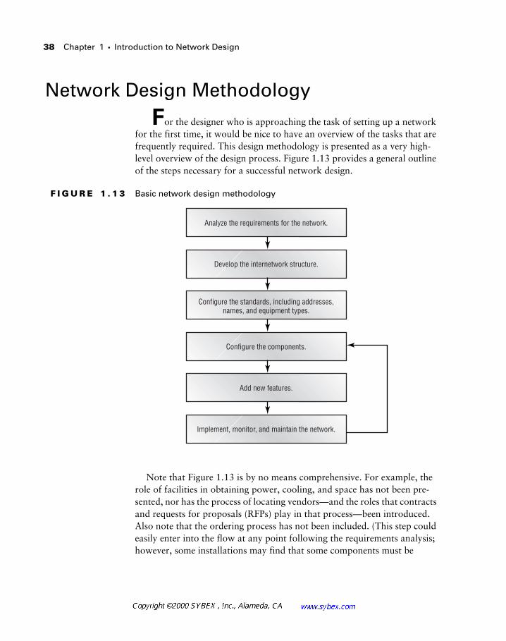
38 Chapter 1 � Introduction to Network Design
Network Design Methodology
For the designer who is approaching the task of setting up a network for the first time, it would be nice to have an overview of the tasks that are frequently required. This design methodology is presented as a very high-level overview of the design process. Figure 1.13 provides a general outline of the steps necessary for a successful network design.
F I G U R E 1 . 1 3 Basic network design methodology
Note that Figure 1.13 is by no means comprehensive. For example, the role of facilities in obtaining power, cooling, and space has not been pre-sented, nor has the process of locating vendors—and the roles that contracts and requests for proposals (RFPs) play in that process—been introduced. Also note that the ordering process has not been included. (This step could easily enter into the flow at any point following the requirements analysis; however, some installations may find that some components must be
Analyze the requirements for the network.
Develop the internetwork structure.
Configure the standards, including addresses,names, and equipment types.
Configure the components.
Add new features.
Implement, monitor, and maintain the network.
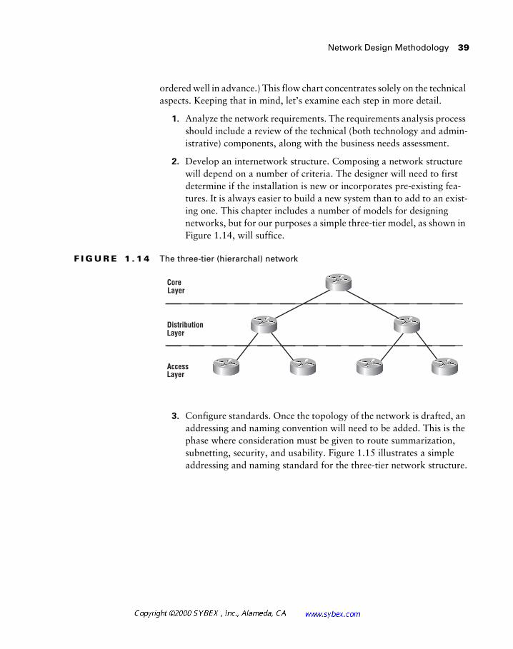
Network Design Methodology 39
ordered well in advance.) This flow chart concentrates solely on the technical aspects. Keeping that in mind, let’s examine each step in more detail.
1. Analyze the network requirements. The requirements analysis process should include a review of the technical (both technology and admin-istrative) components, along with the business needs assessment.
2. Develop an internetwork structure. Composing a network structure will depend on a number of criteria. The designer will need to first determine if the installation is new or incorporates pre-existing fea-tures. It is always easier to build a new system than to add to an exist-ing one. This chapter includes a number of models for designing networks, but for our purposes a simple three-tier model, as shown in Figure 1.14, will suffice.
F I G U R E 1 . 1 4 The three-tier (hierarchal) network
3. Configure standards. Once the topology of the network is drafted, an addressing and naming convention will need to be added. This is the phase where consideration must be given to route summarization, subnetting, security, and usability. Figure 1.15 illustrates a simple addressing and naming standard for the three-tier network structure.
Core
Access
Distribution
Layer
Layer
Layer
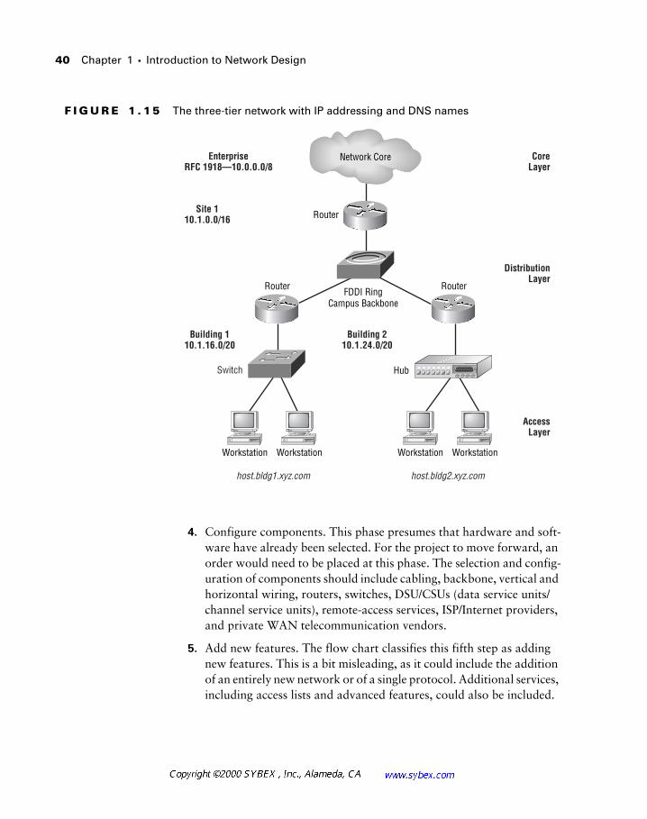
40 Chapter 1 � Introduction to Network Design
F I G U R E 1 . 1 5 The three-tier network with IP addressing and DNS names
4. Configure components. This phase presumes that hardware and soft-ware have already been selected. For the project to move forward, an order would need to be placed at this phase. The selection and config-uration of components should include cabling, backbone, vertical and horizontal wiring, routers, switches, DSU/CSUs (data service units/channel service units), remote-access services, ISP/Internet providers, and private WAN telecommunication vendors.
5. Add new features. The flow chart classifies this fifth step as adding new features. This is a bit misleading, as it could include the addition of an entirely new network or of a single protocol. Additional services, including access lists and advanced features, could also be included.
Switch
Network Core
FDDI RingCampus Backbone
Workstation Workstation Workstation Workstation
Hub
AccessLayer
DistributionLayer
Building 210.1.24.0/20
Building 110.1.16.0/20
Site 110.1.0.0/16
EnterpriseRFC 1918—10.0.0.0/8
CoreLayer
host.bldg1.xyz.com host.bldg2.xyz.com
Router
Router Router
Designing with a Client 41
6. Implement, monitor, and maintain the network. The final step is really a recurrent phase of the network design process. Whether the network is completely new or simply modified, a required step in the project is a review of the initial design requirements, a review of the health of the network, and general administration. Only by reviewing the project (including the nontechnical portions) can a team gain valuable infor-mation that will eventually simplify the next effort and identify future needs for the current project.
Designing with a Client
Let’s walk through a simple network design process. Do not be con-cerned if you are unfamiliar with the specific technologies noted in this sce-nario—the actual details are unimportant. However, a good designer should always have a list of technologies to research and learn, and you may wish to add the unfamiliar components to your list.
The Sales department has requested a DSL-based solution for their team. One of the senior sales executives has read articles touting the benefits of DSL, which has led to this request. Users will want access to corporate data and the Internet at high speeds. In addition, users may be at home, at a cli-ent’s site, or in a hotel. The budget for the project is undefined; however, you are told that there will be funding for whatever it takes.
Stop for a moment and consider the different factors and issues associated with this request. List some of the questions that should be answered.
Here is a short list of preliminary questions:
� How much data will actually be transferred?
� Does the data require security/encryption?
� How often will the user be at home? At a client’s site? At a hotel?
� What protocols are to be used?
� How many users will there be?
Note that some of these questions will not have an answer, or the answer will be vague.
42 Chapter 1 � Introduction to Network Design
The designer will have to make some interesting decisions at this point. The requirement for high-speed access from client sites and hotels is one issue. DSL requires a pre-installed connection. It is not widely available, unlike POTS (plain old telephone service), and is either configured as private (similar to Frame Relay in which companies share switches and other com-ponents, while PVCs keep traffic isolated) or public, which usually connects to an ISP and the Internet. An immediate red flag would be the lack of DSL availability in remote locations. Note that the request specified DSL. Why? Is it because the technology is needed or because it is perceived as newer, bet-ter, and faster?
Depending on the answers, it may still make sense to use DSL for the home. However, the design will still fail to address the hotel and customer sites. Perhaps a VPN (Virtual Private Network) solution with POTS, ISDN, and DSL technologies would work. This solution may include outsourcing or partnering with an ISP (Internet Service Provider) in order to implement the design. Note that at no point in the process have routing protocols, hard-ware components, support, or actual costs been discussed. These factors should be considered once the objectives for the project have been defined.
Network Design in the Real World: Nontechnical Solutions
Network designers should not be afraid to suggest nontechnical solutions in response to requests. For example, consider a request to install a Frame Relay T1 for a connection to another company. There will be a large data transfer every month of approximately 100Mb. The data is not time sensi-tive, and no additional data is anticipated (i.e., neither the frequency of the data nor the volume of data is expected to increase.)
References and Other Sources 43
References and Other Sources
Rather than list a number of references in this section, the authors have decided to provide in Appendix C a listing of reference materials, RFCs (requests for comments), and books to augment the development of network design skills. However, even the material placed in Appendix C will quickly become dated. Therefore, it is recommended that readers use the appendix as a preliminary reference point and then continue on with research at the local library or bookstore or on the Internet.
Readers will find the following types of information in Appendix C.
� Development group Web sites
� Employment search Web sites
� Vendor Web sites
� Relevant RFC numbers
This problem begs a nontechnical solution, especially since the costs for a technical solution, even for Frame Relay, would be very high. As a variation on SneakerNet, why not propose FedExNet? (SneakerNet was one of the most popular network technologies ever used—users simply walked flop-pies and files to recipients.) It is important to consider the alternatives—in this case the requirements did not mandate a technical solution, just a solu-tion. A CD-ROM or tape would easily contain the data, and, at current tariffs, the cost would be less than 1/20th the technical solution. It may not appear as glamorous, but it is secure and reliable. Note these last two points when considering an Internet-based solution, which would also be cheaper than private Frame Relay.
This chapter has already touched upon cost as a significant factor in net-work design, and the majority of these costs are associated with the tele-communications tariff. The tariff is the billing agreement used, and, like home phone service, most providers charge a higher tariff for long-distance and international calls than they do for local ones. Designers should always consider the distance sensitivity and costs associated with their solutions—Frame Relay is typically cheaper than a leased line, for example.
44 Chapter 1 � Introduction to Network Design
Summary
This chapter presented a great deal of material regarding the theories and models used in network design. This information will serve as the foun-dation for later chapters, which will introduce more technical material. While later chapters will focus less attention on the business relationships, always keep the importance of these nontechnical factors in mind when con-sidering technical solutions.
Having completed this chapter, readers should:
� Understand that technology is only one portion of the network design process.
� Be able to describe the benefits of the three-tier model.
� Know the definitions of scalability and adaptability.
� Realize that costs in network design have different meanings and impacts on the business.
� Understand that most good network designs are a collaborative effort.
� Know the primary network design issues:
� What is the problem?
� What future needs are anticipated?
� What is the network’s projected lifespan?
� Be familiar with the considerations of a network design, including those listed below:
� Excessive broadcasts
� Media contention
� Security
� Addressing
� Bandwidth
� New payloads
� Configuration simplification

Summary 45
� Protocol scalability
� Business relationships
� Know the network design methodology.
� Be able to define the role of each layer of the three-tier model.
� Understand the limitations of the three-tier model.
46 Chapter 1 � Introduction to Network Design
Review Questions
1. A small, four-location network might use which of the following net-work designs?
A. A star topology
B. A ring topology
C. A full-mesh topology
D. A star/mesh topology
E. A mesh/ring topology
2. Which of the following are considerations of a good network design?
A. Security
B. Control of broadcasts
C. Bandwidth
D. Media contention
E. All of the above
3. Place the following in chronological order:
A. Develop an internetwork structure
B. Analyze the network requirements
C. Add new features
D. Implement, monitor, and maintain the network
E. Configure standards
4. Why do network designers use the three-tier model?
A. It lends itself to scalable network designs.
B. It costs less to implement three-tier networks.
C. Without three tiers, networks cannot be secured.
D. Business considerations are impossible to integrate without three tiers.

Review Questions 47
5. Which of the following are types of costs?
A. Recurring
B. Episodic
C. Initial
D. Dollar-cost-averaged
6. The network core is designed to:
A. Provide a single point of failure.
B. Provide a central, reliable, and secure area for the transfer of pack-ets from one region to another.
C. Use Layer 2 technology only.
D. Use Layer 3 technology only.
7. Access lists should not be included in:
A. The core.
B. The distribution layer.
C. The access layer.
D. All of the above.
8. When designing DNS domains, which layer lends itself to being the root?
A. The core
B. The distribution layer
C. The access layer
D. DNS domains do not map to network layers.

48 Chapter 1 � Introduction to Network Design
9. Which of the following pieces of information would be important to a network designer at the beginning of the project?
A. The number of users who will use the network
B. The amount of data to be transferred and the types of applications that will be involved
C. The budget for the project
D. The expected lifespan of the network
E. All of the above
10. To implement a full-mesh Frame Relay network for seven locations, the designer would need how many PVCs?
A. 7
B. 6
C. 49
D. 21
11. A designer is specifically addressing a high percentage of broadcasts as a problem in the network. Which of the following would serve as a solution to this problem?
A. Switching
B. Bridging
C. Routing
D. Removal of EIGRP
12. An audit of the network indicates that bandwidth utilization is high on a number of segments. The designer might use which of the following to resolve the problem?
A. Switching
B. Increase in bandwidth
C. Reduction in the number of workstations per segment
D. All of the above
Review Questions 49
13. Access lists might be found at which of the following three-tier model layers?
A. The core layer
B. The distribution layer
C. The access layer
D. The extranet layer
14. The 80/20 rule states which of the following?
A. That 80 percent of the traffic should leave the local subnet.
B. That 20 percent of the traffic should be in the form of broadcasts.
C. That 20 percent of the traffic should remain local.
D. That 20 percent of the traffic should leave the local subnet.
15. Which of the following would not be included as a good network design criteria?
A. Low cost
B. Adaptiveness
C. VLSM
D. Scalablility
16. The network design strives to simplify the move-add-change (MAC) process. Thus, the designer should consider which of the following?
A. DHCP
B. Dynamic VLANs
C. EIGRP
D. OSPF
50 Chapter 1 � Introduction to Network Design
17. Which of the following is the most common trade-off in network design?
A. Size versus features
B. Features versus redundancy
C. Cost versus availability
D. Future capabilities versus scalability
18. Please rate the following designs based on their inherent redundancy.
A. Full mesh
B. Partial mesh
C. Hierarchical
D. Star
19. Hierarchical networks do NOT include which of the following?
A. Three tiers divided with Layer 3 devices
B. Enhanced scalability
C. Easier troubleshooting
D. Fewest hops between end points
20. Based on the model and network characteristics specified in each answer, which would use the greatest number of circuits?
A. Using the mesh model, the network is fully meshed and contains seven sites and a total of seven routers.
B. Using the hierarchical model, there are two access layers per dis-tribution layer with two distribution layer routers and one core and a total of seven routers.
C. Using a ring topology, the network contains seven sites and a total of seven routers.
D. Using a star (hub-and-spoke) topology, the network contains seven sites and a total of seven routers.

Answers to Review Questions 51
Answers to Review Questions
1. A, B, C.
2. E.
3. B, A, E, C, D.
4. A.
5. A, C.
While expenses may appear suddenly, a good design and budget should plan for these as recurring costs.
6. B.
7. A.
The core should be used only for the rapid transfer of data.
8. A.
This question requires a bit of thought, and it is unlikely that it would appear on the exam. The context is that upper layers often can relate to lower layers. While the entire DNS domain could be in all points in the three-tier model, it is likely that the design would break these into subdomains at the distribution tier.
9. E.
10. D.
11. C.
Designers should also consider server and workstation tuning as pos-sible solutions. Recall that Layer 2 does not divide the broadcast domain.
12. D.
13. C.
14. D.

52 Chapter 1 � Introduction to Network Design
15. C.
VLSM is typically part of a good network design, but it is not a criteria for a design.
16. A, B.
17. C.
Cost is always a limiting factor for the network designer.
18. A, B, C, D.
19. D.
A simple hierarchical design would incorporate at least four hops between access layers. A full mesh might keep this number down to one.
20. A.
The math works as follows: A=21, B=6, C=7, and D=6.
Chapter
2
Network Design Technologies
CISCO INTERNETWORK DESIGN EXAM OBJECTIVES COVERED IN THIS CHAPTER:
�
List common reasons that customers invest in a campus LAN
design project.
�
Examine statements made by a client and distinguish the
relevant issues that will affect the choice of campus LAN design
solutions.
�
Define switches, virtual LANs, and LAN emulation.
�
Examine a client’s requirements and construct an appropriate
switched campus LAN solution.
�
Define routing functions and benefits.
�
Examine a client’s requirements and construct an appropriate
campus LAN design solution that includes switches and
routers.
�
Examine a client’s requirements and construct an appropriate
ATM design solution.
�
Construct designs using ATM technology for high-performance
workgroups and high-performance backbones.
�
Upgrade internetwork designs as the role of ATM evolves.
The first chapter of this book focused on the many nontechni-cal facets of network design. This chapter will depart from the nontechnical components and begin to develop the technical components.
The technical components of networking include many different ele-ments. All of these elements require consideration by the network designer in virtually every design. Decisions made in one area can quickly force compro-mises in another area that may not be fully anticipated. While a full expla-nation of some of the common issues is beyond the scope of this text (and the exam), the text will take some steps to identify and address these issues.
The network design technologies include the components of the first three OSI model layers. Repeaters, hubs, switches, and routers all work in differ-ent ways to integrate within the infrastructure. Designers must understand the differences between these devices and their functions. They must also consider newer technologies and more complex systems. These may include ATM, ATM LANE, FastEtherChannel (FEC), GigEtherChannel (GEC), and VLAN (virtual LAN) trunking. Some vendors are beginning to deploy Layer 5 switching technology—a development that may alter design models in future years.
Network Technologies in Local Area Networks
As defined in Chapter 1, most networks are deployed to meet the needs of the business. Businesses that invest in campus LAN projects typi-cally benefit from the collaborative advantages that result from these expen-ditures. Reduced costs also promote the deployment of a LAN—imagine if companies bought stand-alone printers for each desktop, for example. The net result would be substantial added expense and a single tactical solution that could not resolve subsequent issues.
Network Technologies in Local Area Networks 55
At times it seems as if the technology that drives networks is constantly changing. However, it might be simpler to think of the process as more evo-lutionary. For example, switches are simply an extension from bridges and other technologies to their predecessors.
The importance of understanding the customer needs was presented in Chapter 1, along with a number of high-level criteria for integrating the busi-ness needs with the network design. The designer will need to take these cri-teria and apply technology appropriate to both the current requirements and to a logical growth path that works to preserve the investment.
In the first presentations of network design using switches, vendors advo-cated the transport of VLANs across the backbone. Recall that VLANs, or virtual LANs, are logical groupings of the broadcast domain. The logic was that workgroups could be physically isolated while retaining the benefits of operating at Layer 2. This design was primarily based on the fact that rout-ers, or any Layer 3 processing, would be slower than switching packets from end to end. Given the evolution of the technologies, vendors now advocate the sole use of Layer 3 processing in the core.
Before dismissing the use of Layer 2 in the core, consider both the posi-tives and negatives of such use. Layer 2 provides a secure environment wherein all traffic is local. Connections between nodes require neither pro-cessing by a router nor the conversions that are performed in routing. The number of router interfaces can be lower and the configuration of the net-work is simplified. All of these benefits gave administrators cause to pursue the design model in the mid-1990s.
However, as the technology advanced and Layer 3 processing moved closer to wire speeds, it became less advantageous from a performance per-spective to avoid routers. The benefits of broadcast control and geographic isolation became more attractive to designers, and while it could still cost more to create additional VLANs, integration of Layer 3 into the switching fabric eroded this disadvantage as well.
Within the context of the current exam, switches are purely Layer 2 devices, and the integration of routing and other technologies is out of scope unless explicitly referenced.
Designers should also consider business needs when evaluating technolo-gies and the subsequent changes in direction that occur. While vendors profit substantially from the purchase of new equipment, the business may not
56 Chapter 2 � Network Design Technologies
share in the benefits from the upgrade. The corporation is interested in reli-able economic growth, and the network is typically the mechanism by which business is performed—it rarely is the business itself. Consider this in a dif-ferent perspective. Corporation X makes hockey sticks. It doesn’t matter whether the network is using EIGRP on FastEthernet with HSRP (Hot Standby Router Protocol). It does matter whether the network operates dur-ing the two shifts that manufacture the product and during the end-of-month financial reports. Upgrading to ATM may sound desirable, but if the net-work is stable on Ethernet and isn’t growing, upgrading is unlikely to garner a return on investment.
In the same context, the designer should focus on the specific problem at hand and work to resolve it within any existing constraints. With new designs, it becomes more important to anticipate potential problems, which is the mark of an excellent designer. Cisco categorizes network problems into three specific areas: media, protocols, and transport. While these parameters may be oversimplified, they should help novice designers iden-tify and resolve the issues that will confront them.
Media The media category relates to problems with available band-width. Typically, this refers to too high a demand on the network as opposed to a problem with the media itself. Designers would likely use switches and segmentation to address this category of problem, although links of greater bandwidth would also be practical.
Protocols Protocol issues include scalability problems. Many of the chapters in this text will discuss the problems with certain protocols due to their use of broadcasts. This usage may lead to congestion and perfor-mance problems, which would not be resolved with media modifications per se. Protocol issues are typically resolved with migrations to the Inter-net Protocol (IP), although some tuning within the original protocol can provide relief as well. IP is suggested primarily because of current trends in the market and advances that have increased its scalability.
Transport Transport problems typically involve the introduction of voice and video services in the network. These services require more con-sistent latency than traditional data services. As a result, transport prob-lems are typically resolved with recent Ethernet QoS (quality of service) enhancements or ATM switches. Transport issues may seem similar to media problems, but there is a difference. The transport category incor-porates new time-sensitive services, whereas the media category is tar-geted more toward increased demand.
Network Technologies in Local Area Networks 57
LAN Technologies
In modern network design, there are five common technologies, as enumer-ated below. Each provides unique benefits and shortcomings in terms of scal-ability and cost. However, many corporations also consider user familiarity and supportability along with these factors.
Ethernet Includes FastEthernet, GigabitEthernet, and enhancements still under development to increase theoretical bandwidth. Ethernet is the most frequently deployed networking technology. Many network designs have included switched-to-the-desktop Ethernet, which increases avail-able bandwidth without requiring a change at the workstation.
Token Ring Token Ring is a very powerful networking technology that was frequently deployed in large financial institutions that started with mainframe systems. However, it never met with the success of Ethernet—primarily because of the expense involved. Token Ring adapters were always significantly more expensive than Ethernet NICs (network inter-face cards), and many firms based their decisions on financial consider-ations. In later years, Ethernet was enhanced to FastEthernet and switching was added. This overcame many of Token Ring’s positive attributes and placed it at a significant disadvantage in terms of performance (16MB early-release Token Ring versus 100MB full-duplex Ethernet).
FDDI Fiber Distributed Data Interface and its copper equivalent, CDDI, were very popular for campus backbones and high-speed server connec-tions. Cost has prevented FDDI from migrating to the desktop, and advances in Ethernet technology have eroded a significant portion of the FDDI market share.
ATM Asynchronous Transfer Mode was the technology to kill all other technologies. It is listed here as ATM, as opposed to ATM LANE, dis-cussed below. In this context it is not considered a LAN technology, but ATM is frequently considered along with ATM LANE in LAN designs. There is no question that ATM will expand as a powerful tool in wide area network design and that many companies will first accomplish the integration of voice, video, and data using this technology. However, ven-dors are beginning to map IP and other transports directly onto fiber—especially using the dense wavelength division multiplexing (DWDM) that has matured in the past few years. This technology may ultimately remove ATM from the landscape. Note that some large campus installations use ATM to replace FDDI rings—a design that does not include LANE.
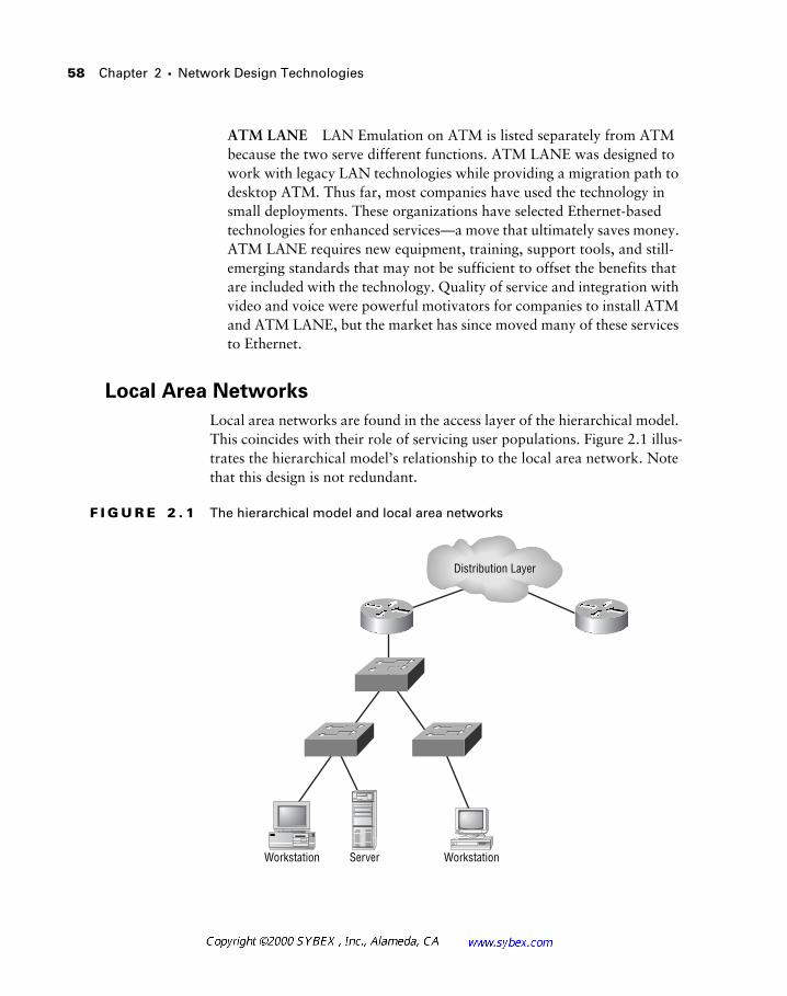
58 Chapter 2 � Network Design Technologies
ATM LANE LAN Emulation on ATM is listed separately from ATM because the two serve different functions. ATM LANE was designed to work with legacy LAN technologies while providing a migration path to desktop ATM. Thus far, most companies have used the technology in small deployments. These organizations have selected Ethernet-based technologies for enhanced services—a move that ultimately saves money. ATM LANE requires new equipment, training, support tools, and still-emerging standards that may not be sufficient to offset the benefits that are included with the technology. Quality of service and integration with video and voice were powerful motivators for companies to install ATM and ATM LANE, but the market has since moved many of these services to Ethernet.
Local Area Networks
Local area networks are found in the access layer of the hierarchical model. This coincides with their role of servicing user populations. Figure 2.1 illus-trates the hierarchical model’s relationship to the local area network. Note that this design is not redundant.
F I G U R E 2 . 1 The hierarchical model and local area networks
Distribution Layer
Workstation Server Workstation
Network Technologies in Local Area Networks 59
Designers require a number of components in the design and administra-tion of the LAN. These include cabling, routers, and concentrators (hubs or switches).
Within this text, routers are considered to be the only Layer 3 devices, while switches operate at Layer 2. This is consistent with the current exam objec-tives; however, modern switching products now address Layers 3 and 4, while development is in progress to expand awareness to Layer 5. This will improve caching and QoS functionality. Some consider these new switches to be little more than marketing hype, but there is little doubt that increased knowledge regarding the content of data will augment security and prioritiza-tion of flows. This text will not enter the debate of switch versus router—it will simply define switching as a Layer 2 function and routing as a Layer 3 func-tion. Note that some hierarchical models use Layer 2 switches as the access layer, with the first router at the distribution layer.
Cabling
Designers often ignore cabling in the network design process, although up to 70 percent of network problems can be attributed to cabling issues. Respon-sibility for infrastructure is left to facilities staff or other organizations, espe-cially within large corporations. This is certainly not the best methodology for effective network deployments. The cable plant is the single most impor-tant factor in the proper maintenance of the network and, as noted in Chap-ter 1, the cable plant has the longest life cycle of any network component.
Most LAN infrastructures continue to use copper-based cable for the desktop and fiber for riser distribution. Placing fiber at the desktop is slowly becoming popular, and with the introduction of RJ-45-style (MT-RJ) con-nectors, the space required for these installations is not an issue. Designers should be familiar with the certified maximum distances that are permitted for the various media. The specifications incorporated into the physical media standard for each protocol virtually guarantee successful connectivity. While such values are more than rules of thumb, they are easy to incorporate into network designs and insulate the designer from having to understand the detailed electrical criteria involved in twisted-pair wiring and fiber optics. Table 2.1 notes the physical media distance limitations.
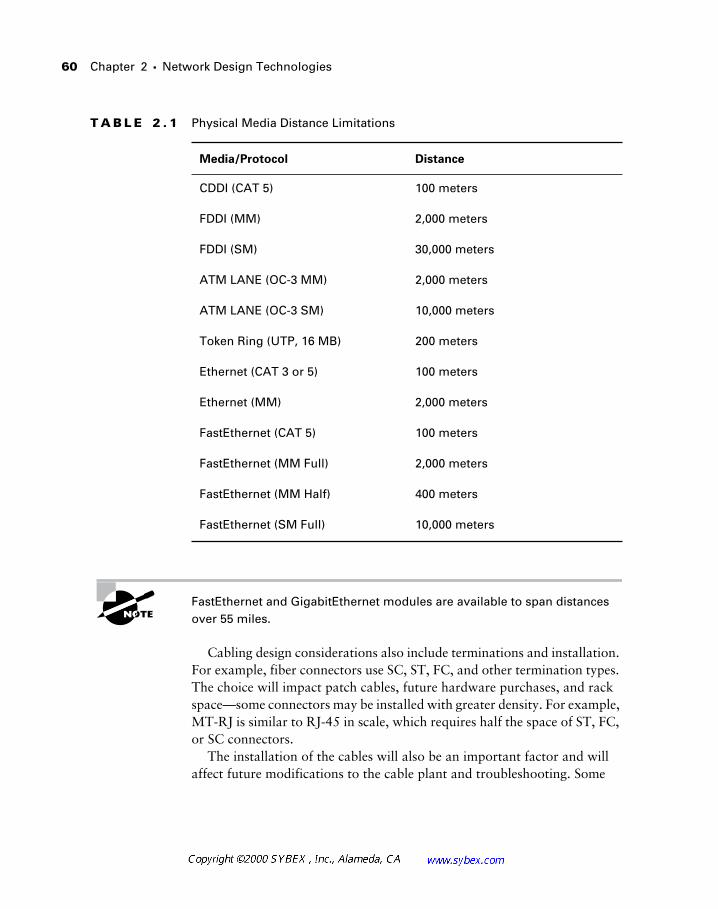
60 Chapter 2 � Network Design Technologies
FastEthernet and GigabitEthernet modules are available to span distances over 55 miles.
Cabling design considerations also include terminations and installation. For example, fiber connectors use SC, ST, FC, and other termination types. The choice will impact patch cables, future hardware purchases, and rack space—some connectors may be installed with greater density. For example, MT-RJ is similar to RJ-45 in scale, which requires half the space of ST, FC, or SC connectors.
The installation of the cables will also be an important factor and will affect future modifications to the cable plant and troubleshooting. Some
T A B L E 2 . 1 Physical Media Distance Limitations
Media/Protocol Distance
CDDI (CAT 5) 100 meters
FDDI (MM) 2,000 meters
FDDI (SM) 30,000 meters
ATM LANE (OC-3 MM) 2,000 meters
ATM LANE (OC-3 SM) 10,000 meters
Token Ring (UTP, 16 MB) 200 meters
Ethernet (CAT 3 or 5) 100 meters
Ethernet (MM) 2,000 meters
FastEthernet (CAT 5) 100 meters
FastEthernet (MM Full) 2,000 meters
FastEthernet (MM Half) 400 meters
FastEthernet (SM Full) 10,000 meters
Network Technologies in Local Area Networks 61
companies require a “home run” from the panel to the station. This type of installation uses a single, continuous wire. In contrast, other organizations install riser cable that terminates to a frame in the closet. These terminations cross-connect to the stations. This type of installation is often cheaper and permits additional flexibility. In either configuration, punch-down work and other maintenance should occur at a single point whenever possible. It is also extremely important to document what is installed.
Professional cable installers should be used whenever possible. A good cable installer will have both the equipment and training required to adhere to the standards and to properly install and dress the cables. A good cable installa-tion should be capable of service for up to 15 years and is a significant expense.
Network Design in the Real World: Cabling
A recent trend in data installations is to use Category 5E, 6, or 7 copper wire to the desktop. These installations operate on the premise that the greater electrical characteristics of this wire will provide a future-proof migration path as newer technologies and greater bandwidths to the desktop become commonplace. Given the upcoming 10Gbps Ethernet standard and the resulting 1000-fold increase in theoretical bandwidth (2000-fold with full-duplex technology), it is clear that higher capacity links to the desktop will be in networking’s future.
On the other hand, fiber proponents will be quick to point out the advan-tages of augmenting copper installations with glass or forgoing copper altogether. Today, this method still adds a significant premium to the instal-lation and material costs, but it may yield a less-expensive solution in the long term.
At this point, it is too difficult to provide a long-term recommendation—each installation is different and each company unique. Factors to consider include current applications and services, a lease versus ownership of the facility, and the company’s budget.
62 Chapter 2 � Network Design Technologies
Routers
Routers are perhaps the most significant tool in the network designer’s rep-ertoire of dealing with broadcasts in the enterprise. As noted in Chapter 1, it would be ideal to reduce the number of broadcasts in the network at the source, but this is not an option under most circumstances.
Unlike Layer 2 devices, routers block broadcasts from leaving the net-work segment. In other words, routers define the broadcast domain. This is an important consideration, as few protocols will scale beyond 200 nodes per broadcast domain—thus, routers are usually needed in inefficient multi-protocol networks of over 200 nodes.
There are other benefits to routers as well. Routers convert between dif-ferent media—for example, FDDI and Ethernet. The Catalyst switch (along with most other multiprotocol switches on the market) will also perform this function, but many designers still consider the use of a router to be superior when performing a media conversion. Routers also impose a logical struc-ture on the network, which is frequently necessary when designing large environments. Lastly, routers are very useful for implementing policies regarding access. Access control lists (ACLs) may be used to block access to certain devices in the network or to filter informational packets regarding services (an IPX SAP access list, for example).
One recommendation that is easily made, however, is that you personally interview all cable installers before hiring them. Make sure that a foreman is assigned to your project, in addition to a project manager. Ask for refer-rals and check them. Also, look for certifications—not only because they are required (by law or insurance policy), but also because they help to ensure a consistent installation.
Also, make certain that you have a qualified person review the installation before you sign off on it. That person should look for kinks in the cable that have been straightened, improper labeling, poor or missing documenta-tion, compressed bundles (use Velcro tie-wraps, not nylon), and untwisted terminations. It does little good to buy Category 7 cable and find that the installer left an inch of space between the panel and the twists.
As previously noted, cable problems can be some of the most difficult to troubleshoot. While equipment and installations have improved, this caveat still holds true.
Network Technologies in Local Area Networks 63
While the performance of routers has improved significantly in the past few years, any device at Layer 3 must perform additional processing on each packet in order to function. Therefore, the downside of routers is usually their latency and packets-per-second (PPS) performance. Newer routing technologies use network data-flow-based switching and other techniques to route only the first packets and then switch the remainder of the flow.
Bridges and Switches
Switches build upon the same technology as bridges, but during their evolu-tion switches have added features to their offerings. In addition, switches fre-quently operate at “wire speed,” i.e., any amount of data entering the port will be processed and forwarded without the need to discard the frame. This is a substantial improvement from the first generation of bridges, in which a burst of frames could quickly saturate the buffers.
Network Design in the Real World: Routers
During the late 1990s, router technology changed substantially. This advancement is best seen in the Catalyst 6500 series (with the Multilayer Switch Feature Card), Catalyst 8500 series switches, and the 12000 GSR series router products from Cisco.
Each of these Layer 3 devices departs from the traditional bus technologies found in the 7500 series routers (which are still mainstream core products) and uses forms of a non-blocking “switch” fabric between the line cards. In addition, the 12000 GSR (Giga Switch Router) provides some insight into the future of network routing—all traffic on the backplane is converted into cells and each line card maintains its own processor and routing table. (Note that these cells are not ATM cells). The 12000 product is intended to terminate OC-12 and OC-48 connections in the core—predominately in ISP (Internet Service Provider) installations. However, it wasn’t that long ago that ISPs were the only ones using BGP. Today, more and more large com-panies are moving to the Internet design model for their private networks. Predictably, the GSR and routers developed from this technology will find their way into the data center.
64 Chapter 2 � Network Design Technologies
One of the keys to obtaining performance from a switch is the proper design of the network. Resources, or those devices that service many users, should be provided with the fastest ports available on the switch. Stated another way, it would be poor design to put a file server on a 10MB interface servicing 100MB workstations. The greatest bandwidth should always be allocated to servers and trunk links.
Technically, switches are defined within Layer 2 of the OSI model, and Cisco continues to use this definition. However, as noted in the previous sec-tion, modern switches are greatly expanding upon the definition of their original role. For the purposes of this discussion, switches forward frames based only on the MAC layer address.
Switches are also responsible for maintaining VLAN information and may isolate ports based on the end-station MAC address, its Layer 3 address (although forwarding decisions are still based at Layer 2), or the physical port itself.
Most switches operate in one of two forwarding modes. Cut-through switches forward frames as soon as the destination address is seen. No CRC (cyclical redundancy check) is performed, and latency is consistent regard-less of frame size. This configuration can permit the forwarding of corrupted frames. The second forwarding mode is called store-and-forward. The entire frame is read into memory, and the CRC is performed before the switch for-wards the frame. This prevents corrupted frames from being forwarded, but latency is variable and greater than with cut-through switching.
Although switches are defined in the main text, designers should consider the “real-world” state of the technology. Layer 3 switching routers are capable of handling basic LAN-based Layer 3 functions, including routing and media conversion. Newer switching products are adding Layers 4 and 5 to their for-warding and processing lookups. This high-speed LAN-optimized routing technology is particularly important when considering load-balancing and queuing, because additional information regarding the packet flow can greatly increase the efficiency of the overall network capacity.
Network Technologies in Local Area Networks 65
Summary of Routing and Switching
This overview of the LAN technologies provides the designer additional information about routing and switching technologies. This information is crucial to understanding the methods for designing scalable networks. Designers should consider the differences in broadcast and collision control and should also take note of loop prevention.
Hubs and repeaters Hubs and repeaters work at Layer 1 of the OSI ref-erence model. No filtering or blocking occurs, and they are used to extend cable length.
Bridges and switches Bridges and switches limit the collision domain but not the broadcast domain. Bridges and switches control loops with the Spanning-Tree Protocol (STP). Switches are considered high-speed, multi-port transparent bridges, with advanced features. These advanced fea-tures include broadcast suppression and VLAN trunking. Bridges and switches both operate at Layer 2 (the MAC layer). Switches also incorpo-rate bandwidth flexibility—for example, a LAN using a hub shares all bandwidth among the stations. Thus, 10 stations must contend for a sin-gle 10Mbps network. Installation of a switch immediately provides each station with a dedicated 10Mbps, or a total theoretical bandwidth of 100Mbps. The limitation moves to the switch’s backplane and buffers. In the same context, a shared FDDI ring operating at 100Mbps can be replaced with an ATM switch operating at OC-3 speeds (155Mbps). Each port has a dedicated link. Many designers divide shared media by the number of devices—thus, 10 stations on an FDDI ring will each receive 10Mbps. This is a simplified method for estimating performance increases.
Routers Routers operate at Layer 3, limiting the collision and broadcast domains. Loops are handled within the routing protocol, using mecha-nisms such as split-horizon and time-to-live counters. Routers require logical addressing.
Nodes
Network design can be a precise exercise in which the designer knows exactly how much data will be sent across the network and when these trans-missions will occur. Unfortunately, such accuracy would be short-lived and extremely time-consuming to obtain. General guidelines are actually just a means of simplifying the technical process while maintaining sufficient accuracy.
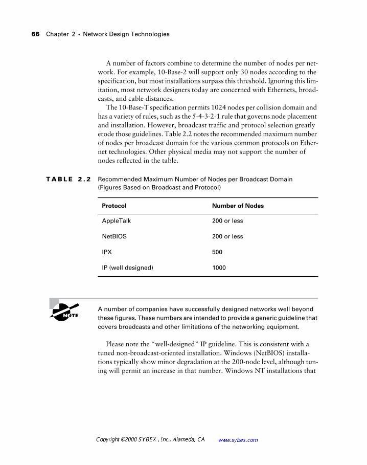
66 Chapter 2 � Network Design Technologies
A number of factors combine to determine the number of nodes per net-work. For example, 10-Base-2 will support only 30 nodes according to the specification, but most installations surpass this threshold. Ignoring this lim-itation, most network designers today are concerned with Ethernets, broad-casts, and cable distances.
The 10-Base-T specification permits 1024 nodes per collision domain and has a variety of rules, such as the 5-4-3-2-1 rule that governs node placement and installation. However, broadcast traffic and protocol selection greatly erode those guidelines. Table 2.2 notes the recommended maximum number of nodes per broadcast domain for the various common protocols on Ether-net technologies. Other physical media may not support the number of nodes reflected in the table.
A number of companies have successfully designed networks well beyond these figures. These numbers are intended to provide a generic guideline that covers broadcasts and other limitations of the networking equipment.
Please note the “well-designed” IP guideline. This is consistent with a tuned non-broadcast-oriented installation. Windows (NetBIOS) installa-tions typically show minor degradation at the 200-node level, although tun-ing will permit an increase in that number. Windows NT installations that
T A B L E 2 . 2 Recommended Maximum Number of Nodes per Broadcast Domain (Figures Based on Broadcast and Protocol)
Protocol Number of Nodes
AppleTalk 200 or less
NetBIOS 200 or less
IPX 500
IP (well designed) 1000
Network Technologies in Local Area Networks 67
utilize WINS as opposed to broadcast-based server discovery typically scale very well. When combining protocols, it is best to use the smaller number and include a factor for the added broadcasts and other traffic. For example, an installation with both Windows and Macintosh systems would best be kept to approximately 150 nodes. An installation with Novell and Unix might be capable of 400 nodes, although an analysis of RIP/SAP traffic and other criteria is likely warranted.
The 5-4-3-2-1 rule was used in the design of 10MB Ethernet networks with repeaters. It is not applicable with switches and faster Ethernet installations. The rule stated that Ethernet networks could have the following: five seg-ments, four repeaters, three populated, two unpopulated, and one network. This rule was a guide to prevent collisions and contention problems that would pass through repeaters.
Trunking in Network Design
A powerful tool for the modern network designer is trunking technology, which combines multiple VLANs onto a single physical circuit. This design permits a single interface to support numerous networks—reducing costs and making more ports available for user connectivity. Trunks may be used between switches and routers, as shown in the following figures, or between switches. Switch-to-switch installations are more common, although this trend is changing. Designers should also note that trunking technology is available on network interface cards for server connections. This design may be used to provide a local presence from one server onto a number of subnets without using multiple NICs. Consider Figure 2.2, which illustrates a non-trunked VLAN installation.
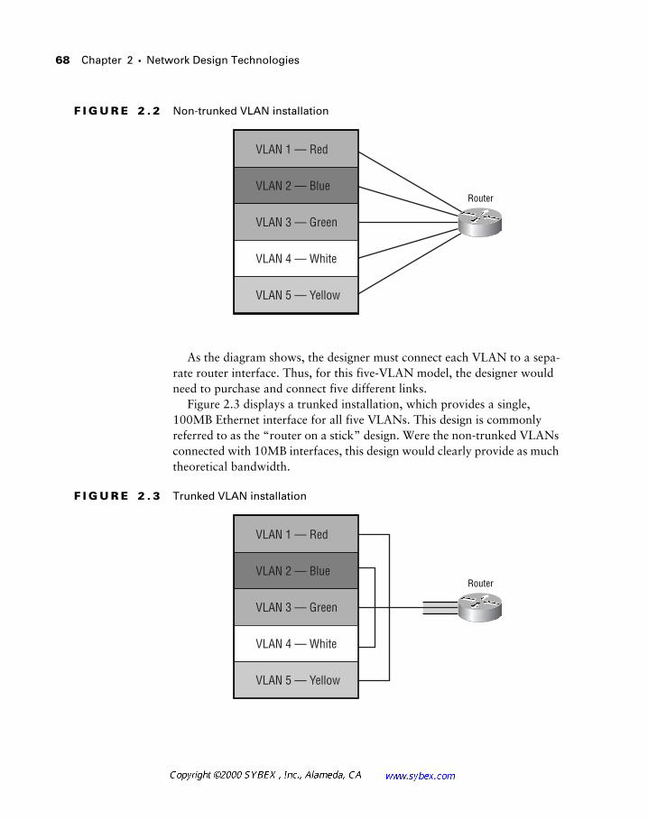
68 Chapter 2 � Network Design Technologies
F I G U R E 2 . 2 Non-trunked VLAN installation
As the diagram shows, the designer must connect each VLAN to a sepa-rate router interface. Thus, for this five-VLAN model, the designer would need to purchase and connect five different links.
Figure 2.3 displays a trunked installation, which provides a single, 100MB Ethernet interface for all five VLANs. This design is commonly referred to as the “router on a stick” design. Were the non-trunked VLANs connected with 10MB interfaces, this design would clearly provide as much theoretical bandwidth.
F I G U R E 2 . 3 Trunked VLAN installation
Router
VLAN 1 — Red
VLAN 2 — Blue
VLAN 3 — Green
VLAN 4 — White
VLAN 5 — Yellow
Router
VLAN 1 — Red
VLAN 2 — Blue
VLAN 3 — Green
VLAN 4 — White
VLAN 5 — Yellow
Network Technologies in Local Area Networks 69
However, many administrators and designers would fret about taking five 100MB interfaces and reducing them to a single 100MB trunk. While their concern is clearly justified, each installation is different. Fortunately, there is a compromise solution that can provide ample bandwidth and retain some of the benefits found in trunking.
Cisco has introduced EtherChannel technologies into the switch and router platforms. This configuration disables the spanning tree and binds up to four links to provide four times the bandwidth to the trunk. This solution works well in practice for a number of reasons, including:
� It is rare for all VLANs to require bandwidth concurrently in produc-tion networks. This fact allows for substantial oversubscription of the trunk without providing underutilized bandwidth.
� EtherChannel links may continue to provide connectivity following a single link failure, which can be an additional benefit in fault-tolerant designs. Normally, this addresses potential port failures on the router.
� The creation of new VLANs frequently requires the designer to order hardware to support the VLAN. Extra hardware is not a factor when combining trunking with channeling.
� Newer network designs make use of multilayer switching—including Layer 3 path-selection switching. These technologies significantly reduce the number of packets requiring the router, as they are routed once and switched for subsequent packets.
EtherChannel technology is independent of trunking technology, and the two may be combined. The concept is that two or more channels may be used to provide additional bandwidth for a single VLAN or trunk—thus, the link between two switches could operate at up to 400Mbps full-duplex (bonding four 100Mbps full-duplex links). The following sections describe the various trunking protocols.
ISL
The Inter-Switch Link (ISL) protocol adds a 30-byte encapsulation header to each frame. This encapsulation tags the frame as belonging to a specific VLAN. ISL is proprietary to Cisco, and while other vendors (including Intel) have licensed the technology, it is slowly losing market share to the ratified IEEE 802.1q standard. ISL provides a great deal of information in its head-ers, including a second CRC in the encapsulation. ISL trunks can be
70 Chapter 2 � Network Design Technologies
deployed between routers and switches, switches and switches, and servers and switches or routers.
It is likely that Cisco will migrate away from the ISL protocol in favor of 802.1q. Designers should consider this factor when evaluating the protocol. Such a migration, should it occur, will likely take many years to come to fruition.
802.1q
The IEEE 802.1q standard provides a low-overhead method for tagging frames. Since it is an open standard, most designers select 802.1q when using non-Cisco equipment or to avoid committing to a single vendor. The 802.1q specification adds four octets of header to each frame. This header identifies the frame’s VLAN membership, but it does not include a CRC checksum for validation of the header. This is not a significant issue in most reliable net-works. The reduced header, compared to ISL, and lack of CRC greatly diminishes the overhead associated with this trunking technology.
Both ISL and 802.1q may cause incorrectly configured network devices to report giants (oversized frames). These “giant” frames are beyond the spec-ified number of octets, as per the Ethernet standard. It is important to under-stand that both the ISL and 802.1q specifications increase the maximum number of bytes allowed—in contrast to traditional Ethernet.
802.10
FDDI may be used as a trunking medium in VLAN networks by incorporat-ing the 802.10 protocol, which was originally developed to provide Layer 2 security. However, the use of the Security Association Identifier, or SAID, permits assignment of a VLAN ID. SAID provides for 4.29 billion VLANs.
The 802.10 encapsulation consists of a MAC header followed by a clear header. The clear header is not encrypted and consists of the 802.10 LSAP, or Link State Access Protocol (LSAPs are defined by the IEEE and occupy the LLC portion of the frame, comprising the destination service access point, source service access point, and control byte), the SAID, and an optional Management Defined Field, or MDF. The standard provides for a protected
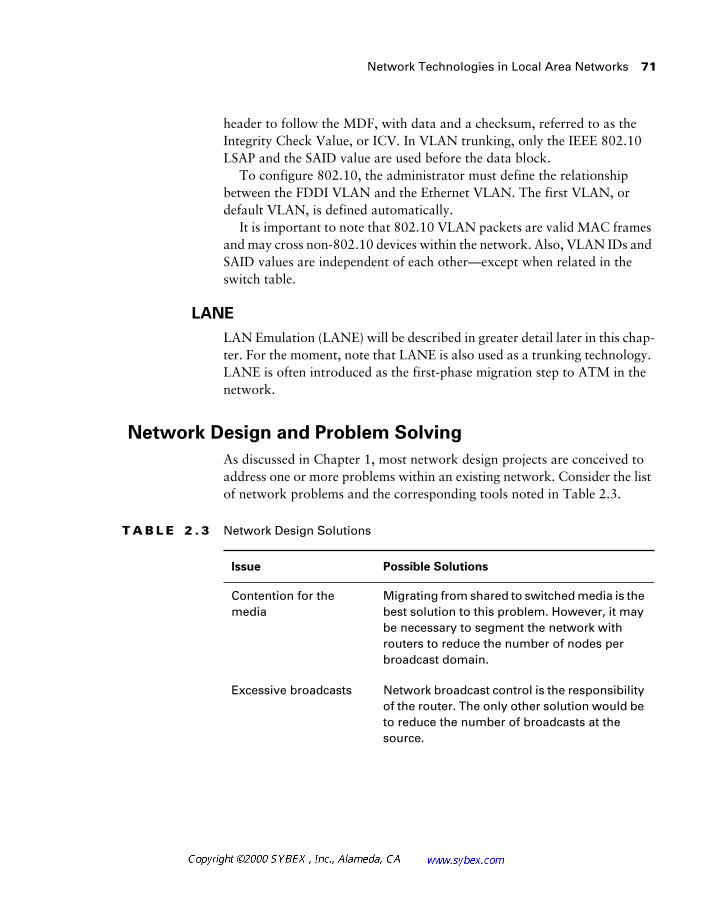
Network Technologies in Local Area Networks 71
header to follow the MDF, with data and a checksum, referred to as the Integrity Check Value, or ICV. In VLAN trunking, only the IEEE 802.10 LSAP and the SAID value are used before the data block.
To configure 802.10, the administrator must define the relationship between the FDDI VLAN and the Ethernet VLAN. The first VLAN, or default VLAN, is defined automatically.
It is important to note that 802.10 VLAN packets are valid MAC frames and may cross non-802.10 devices within the network. Also, VLAN IDs and SAID values are independent of each other—except when related in the switch table.
LANE
LAN Emulation (LANE) will be described in greater detail later in this chap-ter. For the moment, note that LANE is also used as a trunking technology. LANE is often introduced as the first-phase migration step to ATM in the network.
Network Design and Problem Solving
As discussed in Chapter 1, most network design projects are conceived to address one or more problems within an existing network. Consider the list of network problems and the corresponding tools noted in Table 2.3.
T A B L E 2 . 3 Network Design Solutions
Issue Possible Solutions
Contention for the media
Migrating from shared to switched media is the best solution to this problem. However, it may be necessary to segment the network with routers to reduce the number of nodes per broadcast domain.
Excessive broadcasts Network broadcast control is the responsibility of the router. The only other solution would be to reduce the number of broadcasts at the source.
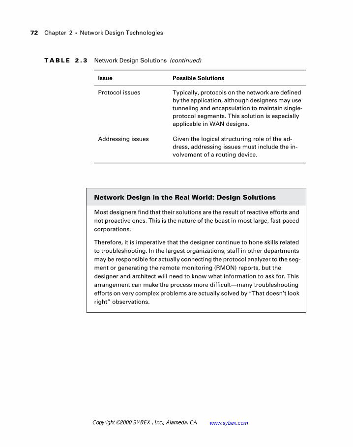
72
Chapter 2 �
Network Design Technologies
Protocol issues Typically, protocols on the network are defined by the application, although designers may use tunneling and encapsulation to maintain single-protocol segments. This solution is especially applicable in WAN designs.
Addressing issues Given the logical structuring role of the ad-dress, addressing issues must include the in-volvement of a routing device.
Network Design in the Real World: Design Solutions
Most designers find that their solutions are the result of reactive efforts and not proactive ones. This is the nature of the beast in most large, fast-paced corporations.
Therefore, it is imperative that the designer continue to hone skills related to troubleshooting. In the largest organizations, staff in other departments may be responsible for actually connecting the protocol analyzer to the seg-ment or generating the remote monitoring (RMON) reports, but the designer and architect will need to know what information to ask for. This arrangement can make the process more difficult—many troubleshooting efforts on very complex problems are actually solved by “That doesn’t look right” observations.
T A B L E 2 . 3
Network Design Solutions
(continued)
Issue Possible Solutions
Physical Topologies 73
Physical Topologies
The physical layout of the network is sometimes dissimilar to the logical and simple layout suggested by the hierarchical model. Consider-ation must be given to access, cabling, distances, shielding, and space.
Most installations use two distinct components for the intra-building con-figuration. These are defined as horizontal and vertical systems.
Vertical systems are typically backbone services and move up through the building. These services are usually run on fiber media, which is capable of greater bandwidth and is less susceptible to electromagnetic interference.
Horizontal systems are almost always copper, but this trend is changing as more desktops are wired for fiber. These installations usually start at a wir-ing closet and are fed under the floor or in plenum (ceiling). The wiring closet will typically contain a switch or hub that links the vertical connections.
The typical network installation will have a single main distribution point for the network. This location would terminate all the vertical runs and all the telecommunications services from outside the building.
One of the best ways to avoid this situation is to generate reports that a lay person can understand. A number of products are available—my favorite is Concord Network Health, although there are others, including Cisco’s RMON tools. The designer can post the resulting reports on a Web site so that users can see the status of the network whenever they wish.
A fear that non-network designers will start to second-guess every issue in the reports is natural, and it will happen from some people. However, the reports can also provide the needed visibility to upper management to jus-tify funding and resources. Most networks hide the problems, so they never get fixed. If you need to be convinced that disclosure is a positive step, take a look at Cisco’s Web site, www.cisco.com. The vast majority of bugs in Cisco’s software are documented and disclosed publicly. Granted, such problems can be embarrassing to the company, but the result over the past few years has been an incredible increase in market share and a vast improvement in the overall product line. Improved service should be the goal of every IT department.
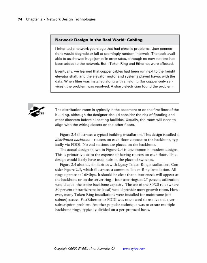
74 Chapter 2 � Network Design Technologies
The distribution room is typically in the basement or on the first floor of the building, although the designer should consider the risk of flooding and other disasters before allocating facilities. Usually, the room will need to align with the wiring closets on the other floors.
Figure 2.4 illustrates a typical building installation. This design is called a distributed backbone—routers on each floor connect to the backbone, typ-ically via FDDI. No end stations are placed on the backbone.
The actual design shown in Figure 2.4 is uncommon in modern designs. This is primarily due to the expense of having routers on each floor. This design would likely have used hubs in the place of switches.
Figure 2.4 also has similarities with legacy Token-Ring installations. Con-sider Figure 2.5, which illustrates a common Token-Ring installation. All rings operate at 16Mbps. It should be clear that a bottleneck will appear at the backbone or on the server ring—four user rings at 25 percent utilization would equal the entire backbone capacity. The use of the 80/20 rule (where 80 percent of traffic remains local) would provide more growth room. How-ever, many Token Ring installations were installed for mainframe (off-subnet) access. FastEthernet or FDDI was often used to resolve this over-subscription problem. Another popular technique was to create multiple backbone rings, typically divided on a per-protocol basis.
Network Design in the Real World: Cabling
I inherited a network years ago that had chronic problems. User connec-tions would degrade or fail at seemingly random intervals. The tools avail-able to us showed huge jumps in error rates, although no new stations had been added to the network. Both Token Ring and Ethernet were affected.
Eventually, we learned that copper cables had been run next to the freight elevator shaft, and the elevator motor and systems played havoc with the data. When fiber was installed along with shielding (for copper-only ser-vices), the problem was resolved. A sharp electrician found the problem.
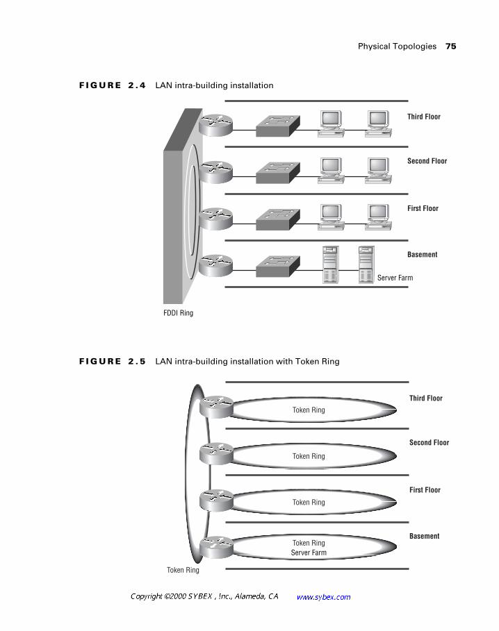
Physical Topologies 75
F I G U R E 2 . 4 LAN intra-building installation
F I G U R E 2 . 5 LAN intra-building installation with Token Ring
FDDI Ring
Third Floor
Second Floor
First Floor
Basement
Server Farm
Third Floor
Second Floor
First Floor
BasementToken Ring
Token Ring
Token Ring
Token Ring
Token Ring
Server Farm
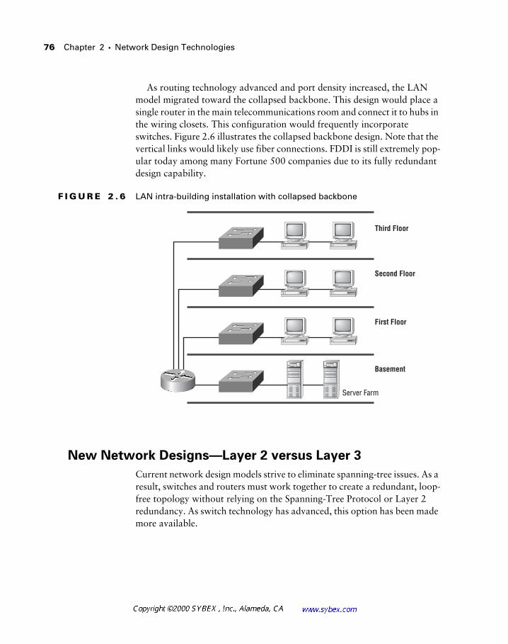
76 Chapter 2 � Network Design Technologies
As routing technology advanced and port density increased, the LAN model migrated toward the collapsed backbone. This design would place a single router in the main telecommunications room and connect it to hubs in the wiring closets. This configuration would frequently incorporate switches. Figure 2.6 illustrates the collapsed backbone design. Note that the vertical links would likely use fiber connections. FDDI is still extremely pop-ular today among many Fortune 500 companies due to its fully redundant design capability.
F I G U R E 2 . 6 LAN intra-building installation with collapsed backbone
New Network Designs—Layer 2 versus Layer 3
Current network design models strive to eliminate spanning-tree issues. As a result, switches and routers must work together to create a redundant, loop-free topology without relying on the Spanning-Tree Protocol or Layer 2 redundancy. As switch technology has advanced, this option has been made more available.
Third Floor
Second Floor
First Floor
Basement
Server Farm
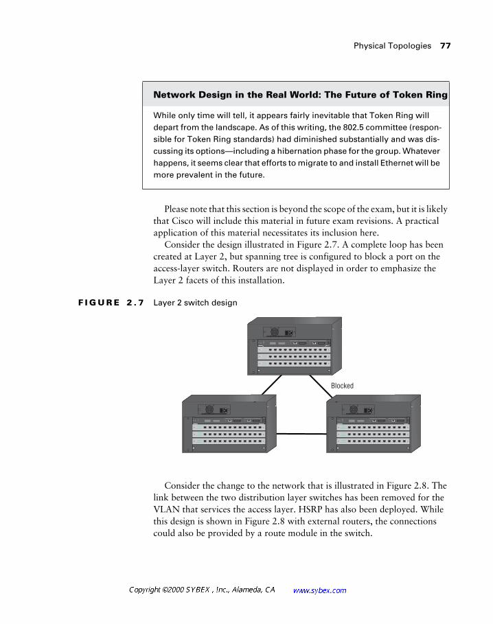
Physical Topologies 77
Please note that this section is beyond the scope of the exam, but it is likely that Cisco will include this material in future exam revisions. A practical application of this material necessitates its inclusion here.
Consider the design illustrated in Figure 2.7. A complete loop has been created at Layer 2, but spanning tree is configured to block a port on the access-layer switch. Routers are not displayed in order to emphasize the Layer 2 facets of this installation.
F I G U R E 2 . 7 Layer 2 switch design
Consider the change to the network that is illustrated in Figure 2.8. The link between the two distribution layer switches has been removed for the VLAN that services the access layer. HSRP has also been deployed. While this design is shown in Figure 2.8 with external routers, the connections could also be provided by a route module in the switch.
Network Design in the Real World: The Future of Token Ring
While only time will tell, it appears fairly inevitable that Token Ring will depart from the landscape. As of this writing, the 802.5 committee (respon-sible for Token Ring standards) had diminished substantially and was dis-cussing its options—including a hibernation phase for the group. Whatever happens, it seems clear that efforts to migrate to and install Ethernet will be more prevalent in the future.
Blocked
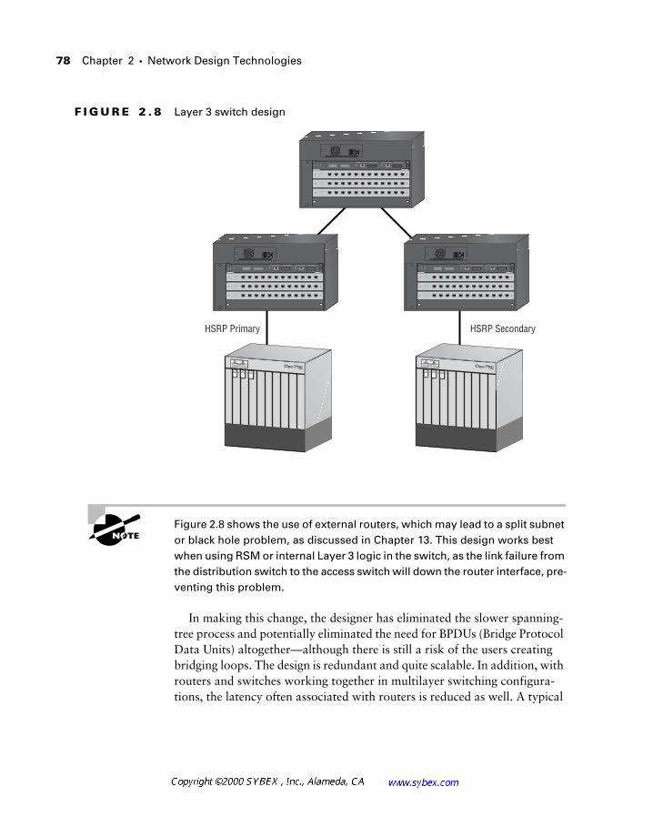
78 Chapter 2 � Network Design Technologies
F I G U R E 2 . 8 Layer 3 switch design
Figure 2.8 shows the use of external routers, which may lead to a split subnet or black hole problem, as discussed in Chapter 13. This design works best when using RSM or internal Layer 3 logic in the switch, as the link failure from the distribution switch to the access switch will down the router interface, pre-venting this problem.
In making this change, the designer has eliminated the slower spanning-tree process and potentially eliminated the need for BPDUs (Bridge Protocol Data Units) altogether—although there is still a risk of the users creating bridging loops. The design is redundant and quite scalable. In addition, with routers and switches working together in multilayer switching configura-tions, the latency often associated with routers is reduced as well. A typical
HSRP Primary HSRP Secondary
Physical Topologies 79
installation using this design model would place a single transit VLAN between the switches. Such a design would still avoid a Layer 2 loop while maintaining a through switch connection. Designers should consider the expected network behavior during both normal and failed scenarios when architecting any configuration.
Designers should not disable the Spanning-Tree Protocol unless they can ensure a loop-free topology.
Network Design in the Real World: Spanning Tree
Spanning tree is perhaps one of the most difficult considerations in network design. This is not due to the protocol or function per se, but rather the need for designers to consider the Layer 2 topology when incorporating Layer 3 functions, including HSRP. It is easy to create an efficient Layer 2 architec-ture and a separate Layer 3 design, but the two ultimately must map together to be manageable and practical. One technique is to make the HSRP primary for the VLAN root bridge. However, there are other tech-niques, including defining multiple default gateways on each host or using proxy ARP.
As of this writing, a new committee was meeting to design a new, faster Spanning-Tree Protocol. This protocol will likely reduce the shortcomings of the original specification, which was never designed to support today’s higher speed networks. However, as presented in the main text, the real issue is whether to design loops into the Layer 2 network at all.
At present, one school of thought on the subject is to avoid loops whenever possible and use Layer 3 routing to provide redundancy—technologies such as HSRP and MPLS (Multiprotocol Label Switching) allow fault toler-ance and switching of Layer 3 packets. The other school of thought believes that spanning tree is still useful but that new features must be added to make it work in today’s networks. Cisco has a number of features that work toward this option, including PortFast and UplinkFast.
80
Chapter 2 �
Network Design Technologies
The Role of ATM
Asynchronous Transfer Mode (ATM) has been the networking technology of the 1990s. Merging the historical divisions between data, voice, and video, ATM was designed and marketed to replace all other technologies in both local and wide area networks.
At the end of the 1990s, it appeared clear that replacement of existing net-works would not occur. Rather, another evolution—merging ATM with leg-acy technologies such as Ethernet—will likely color network design theories into the next century.
However, even with the introduction of 10Gbps Ethernet, there are still situations in which ATM can and should be deployed. Such situations include both LAN and WAN environments.
ATM operates via fixed-length cells. This design contrasts with the variable-length frames found in Ethernet and other technologies. Fixed-length cells provide consistent buffering and latency—allowing integration between voice (constant bit rate) and data (variable bit rate). ATM operates over per-manent virtual circuits and switched virtual circuits.
PortFast is used on switch ports that connect to a single workstation. Under this scenario, the port cannot participate in a loop, so the port should not have to go through a listening-and-learning mode. The port should also not go into blocking—there is no loop potential at this point in the network. It is important to note that this does not disable spanning tree—it simply acti-vates the port faster than the 30-second listening/learning process would require. This feature is recommended for workstations (some of which can fail authentication to the network while the port is blocked). However, a major caveat must be added—the port cannot be connected to a hub or switch. This rule will prevent the loop creation that spanning tree was designed to prevent.
The second feature, UplinkFast, was designed to activate the blocked link quickly in the event of primary failure. Again, there are drawbacks to this feature, but when properly implemented it can greatly extend the function-ality of Layer 2 loops and loop protection.
Physical Topologies 81
As noted previously, ATM uses a fixed-length cell transport mechanism. These cells, at 53 bytes, are substantially smaller than the frame sizes used by Ethernet, Token Ring, and FDDI. In order to migrate between frames and cells, ATM devices perform segmentation and reassembly (SAR). The SAR function frequently became a bottleneck in older switches; however, this overhead is a minor factor today. Designers should discuss SAR processing (cells/frames per second) with their vendors before selecting a product.
ATM is often used in modern network design for WAN links and the inte-gration of voice and data circuits. This type of installation is similar to multi-plexing. In the LAN environment, ATM and ATM LANE installations are frequently used for high-speed campus backbones. This design provides a migration path for pushing ATM toward the desktop. ATM is one option for designers wishing to replace aging FDDI rings.
ATM in the LAN with LANE
LAN deployments of ATM almost always take advantage of LANE, or LAN Emulation, to integrate legacy topologies with ATM. It is unlikely that any organization would allocate sufficient funds to replace their entire existing infrastructure without some migration phase.
LANE was covered in some detail in Sybex’s Cisco LAN Switching Course Study Guide. This section will present an overview of that material for those preparing for the CID exam before the CLSC exam.
LANE makes use of at least three separate logical processes: the LAN Emulation Client (LEC), the LAN Emulation Server (LES), and the broad-cast and unknown server (BUS). A fourth resource is optional but recom-mended. The use of the LAN Emulation Configuration Server (LECS) can greatly simplify the administrative effort needed to deploy LANE.
LAN Emulation Client
The LAN Emulation Client, or LEC, is responsible for data forwarding, address resolution, control functions, and the mapping of MAC addresses to ATM addresses.
LECs are devices that implement the LANE protocol; they may be ATM-equipped workstations, routers, or switches. It is common for an LEC to be a single element on a switch serving numerous Ethernet or Token-Ring
82 Chapter 2 � Network Design Technologies
ports. To the ATM network, it appears that the single ATM LEC is request-ing data—in actuality, the LEC is simply a proxy for the individual requests from the legacy nodes.
LAN Emulation Server
The LAN Emulation Server, or LES, is unique to each ELAN (emulated LAN). The LES is responsible for managing the ELAN and providing trans-parency to the LECs.
Given the interdependency of the LES and BUS services, most references use the term LES/BUS pair to denote the server providing these services.
Broadcast and Unknown Server
Broadcasts and multicasts are quite common in the traditional LAN envi-ronment. Since all stations, even in Ethernet-switched installations, receive all frames destined for a MAC address containing all ones, this process works quite well and serves many upper-layer protocols, including the Address Resolution Protocol, for example.
However, ATM requires that a point-to-point virtual circuit serve all con-nections. This requirement precludes the traditional media-sharing capabil-ities of Ethernet and Token Ring. To resolve this function, the ATM Forum LAN Emulation committee included in the specification a broadcast and unknown server, or BUS. Each ELAN must have its own BUS, which is responsible for resolving all broadcasts and packets that are addressed for unknown, or unregistered, stations. Under the original LANE 1.0 specifica-tion with Cisco ATM devices, without SSRP (Simple Server Redundancy Protocol), only one BUS is permitted per ELAN. Other vendors invented their own redundancy options to augment the specification. SSRP is a pro-prietary method of allowing redundancy in ATM LANE by permitting dual LECS and LES/BUS pairs.
Cisco’s implementation of LANE places the BUS on the same device as the LES. This design will likely change in the future, since it is inconsistent with other vendors’ offerings.
Physical Topologies 83
LAN Emulation Configuration Server
While the LAN Emulation Configuration Server, or LECS, is not required in LANE, administrators frequently find that configuration is greatly simplified when it is employed.
The LECS is similar to Dynamic Host Configuration Protocol (DHCP) servers in the IP world. The workstation queries a server for all information that is needed to participate in the network. With DHCP, this is limited to IP address, default gateway, and DNS/WINS (Domain Name Service/Windows Internet Naming Service) servers, depending on implementation. In ATM, the LECS provides the address information for the LES and BUS to the LEC.
The Initial LANE Connection Sequence
The best way to understand the four components of ATM LANE is to visu-alize the initial startup sequence. This sequence is illustrated in Figure 2.9.
As shown, the client (LEC) must connect with the LES in order to join the ELAN. Most installations make use of the LECS; therefore, the LEC con-nects with the LECS to learn the address of the LES. Note that the LEC could also be configured with the address of the LES for its ELAN, or it could use the well-known address for the LECS. The well-known address is part of the LANE specification and is used when another method is unavailable.
Once the LEC connects with the LES and joins the ELAN, another con-nection is established with the BUS. Both of these VCs (virtual circuits) are maintained, but the LECS connection may be dropped. The LES typically maintains a connection to the LECS.
The CLSC Study Guide from Sybex provides more detail regarding ATM LANE and the Catalyst 5500 platform, including the LS1010.
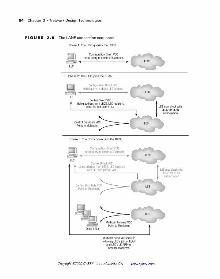
84 Chapter 2 � Network Design Technologies
F I G U R E 2 . 9 The LANE connection sequence
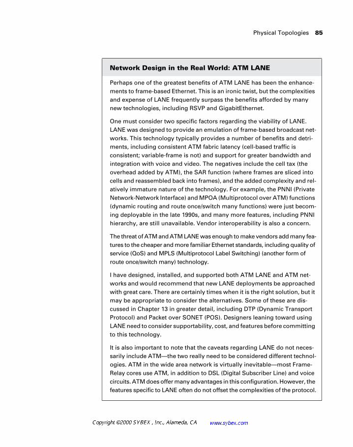
Physical Topologies 85
Network Design in the Real World: ATM LANE
Perhaps one of the greatest benefits of ATM LANE has been the enhance-ments to frame-based Ethernet. This is an ironic twist, but the complexities and expense of LANE frequently surpass the benefits afforded by many new technologies, including RSVP and GigabitEthernet.
One must consider two specific factors regarding the viability of LANE. LANE was designed to provide an emulation of frame-based broadcast net-works. This technology typically provides a number of benefits and detri-ments, including consistent ATM fabric latency (cell-based traffic is consistent; variable-frame is not) and support for greater bandwidth and integration with voice and video. The negatives include the cell tax (the overhead added by ATM), the SAR function (where frames are sliced into cells and reassembled back into frames), and the added complexity and rel-atively immature nature of the technology. For example, the PNNI (Private Network-Network Interface) and MPOA (Multiprotocol over ATM) functions (dynamic routing and route once/switch many functions) were just becom-ing deployable in the late 1990s, and many more features, including PNNI hierarchy, are still unavailable. Vendor interoperability is also a concern.
The threat of ATM and ATM LANE was enough to make vendors add many fea-tures to the cheaper and more familiar Ethernet standards, including quality of service (QoS) and MPLS (Multiprotocol Label Switching) (another form of route once/switch many) technology.
I have designed, installed, and supported both ATM LANE and ATM net-works and would recommend that new LANE deployments be approached with great care. There are certainly times when it is the right solution, but it may be appropriate to consider the alternatives. Some of these are dis-cussed in Chapter 13 in greater detail, including DTP (Dynamic Transport Protocol) and Packet over SONET (POS). Designers leaning toward using LANE need to consider supportability, cost, and features before committing to this technology.
It is also important to note that the caveats regarding LANE do not neces-sarily include ATM—the two really need to be considered different technol-ogies. ATM in the wide area network is virtually inevitable—most Frame-Relay cores use ATM, in addition to DSL (Digital Subscriber Line) and voice circuits. ATM does offer many advantages in this configuration. However, the features specific to LANE often do not offset the complexities of the protocol.
86 Chapter 2 � Network Design Technologies
Summary
This chapter discussed many of the tools and technologies used in the local area network to address problems typically faced by network designers. Newer technologies, such as ATM LANE, were covered, in addition to more traditional tools and technologies, including Ethernet routers and switches.
Specific attention was given to:
� LAN technologies
� Ethernet
� Token Ring
� FDDI
� ATM
� ATM LANE
� Interconnectivity tools
� Repeaters
� Hubs
� Switches
� Routers
� Problem categories
� Media
� Transport
� Protocols
� Trunking protocols
� ISL
� 802.1q
� 802.10
� LANE
Summary 87
The chapter defined key components in network design, including the interconnectivity tools in frame-based networks. It also presented the ATM components: LECS, LEC, LES, and BUS. Finally, it reviewed building topol-ogies, including distributed and collapsed backbones.
Much of the text in the following chapters will focus more on Layers 2 and 3 of the OSI model, so readers will become comfortable with the various functions of hardware in the network and the limitations.
88 Chapter 2 � Network Design Technologies
Review Questions
1. Broadcasts are controlled by which of the following devices?
A. Bridges
B. Repeaters
C. Routers
D. Switches
2. Routers perform which of the following functions?
A. Access control
B. Logical structure
C. Media conversions
D. None of the above
3. Which of the following devices operate at Layer 2 of the OSI model?
A. Routers
B. Gateways
C. Switches
D. Bridges
4. Which of the following is true regarding cut-through switching?
A. The frame is forwarded following verification of the CRC.
B. The frame is forwarded following verification of the HEC.
C. The frame is forwarded upon receipt of the header destination address.
D. The frame is forwarded out every port on the switch.
Review Questions 89
5. Which of the following is true regarding store-and-forward switching?
A. The frame is forwarded following verification of the CRC.
B. The frame is forwarded following verification of the HEC.
C. The frame is forwarded upon receipt of the header destination address.
D. The frame is forwarded out every port on the switch.
6. Negating overhead and conversions, the designer chooses to replace the legacy FDDI ring with an ATM switch attached via OC-3. Assum-ing a backbone of 10 devices, no overhead, and equal distributions, the increase in available bandwidth per device is:
A. 55Mbps
B. 100Mbps
C. 145Mbps
D. 1Gbps
E. 1.54Gbps
7. An Ethernet switch:
A. Defines the collision domain
B. Defines the broadcast domain
C. Defines both the broadcast and collision domains
D. Sends all broadcasts to the BUS (broadcast and unknown server)
8. Which of the following would be a reason to not span a VLAN across the WAN?
A. VLANs define broadcast domains, and all VLAN broadcasts would have to traverse the WAN, which typically uses slow links.
B. Reduced costs, since fewer router interfaces are required.
C. Easier addressing during moves.
D. Non-routed workgroup traffic across geographically removed locations.
90 Chapter 2 � Network Design Technologies
9. Which of the following are considered WAN design issues?
A. Bandwidth
B. Cost
C. Service availability
D. Protocol support
E. Remote access
F. All of the above
10. The Cisco IOS offers some benefits to designers regarding WAN deployments. These benefits do not include which of the following?
A. Compression
B. Filters
C. HTTP proxy
D. On-demand bandwidth
E. Efficient routing protocols, including EIGRP, NLSP, and static routes
11. Which of the following reasons might influence a designer to use a single WAN protocol?
A. Easier configuration
B. More-difficult configuration
C. More-difficult troubleshooting
D. Increased traffic
12. Which of the following is not an open standard?
A. 802.10
B. 802.3
C. 802.1q
D. ISL

Review Questions 91
13. Which of the following would be valid technical reasons to readdress the IP network?
A. Implementation of VLSM
B. Implementation of HSRP
C. Implementation of EIGRP
D. Implementation of OSPF
14. A distributed backbone typically:
A. Contains a single router in the data center
B. Is completely flat within the building or campus
C. Contains multiple routers, typically with one per floor or area
D. Requires the use of ATM LANE, version 2.0
15. ATM uses:
A. 53-byte cells
B. 53-byte frames
C. Variable-length cells
D. Variable-length frames
16. Which of the following is optional in ATM LANE?
A. LEC
B. LES
C. BUS
D. LECS
92 Chapter 2 � Network Design Technologies
17. Which function is used to convert frames to cells?
A. LES
B. LEC
C. LECS
D. SAR
18. Excessive broadcasts are typically resolved with (select three):
A. Switches
B. Tuning of the network protocol
C. Replacement of the network protocol
D. Routers
19. Transport issues differ from media issues in that:
A. Media issues relate to Layer 1, while transport issues relate to Layer 3.
B. Media issues involve voice and video, while transport issues are related to increased demand by existing services.
C. Transport issues incorporate voice and video services, while media issues are limited to the offered load on the network.
D. None of the above.
20. Addressing issues are the responsibility of:
A. Hubs
B. Servers
C. Switches
D. Routers

Answers to Review Questions 93
Answers to Review Questions
1. C.
2. A, B, C.
3. C, D.
4. C.
5. A.
6. C.
FDDI operates at 100Mbps. With 10 shared stations, each station receives 10Mbps. OC-3 switched offers 155Mbps per station.
7. A.
8. A.
9. F.
10. C.
11. A.
12. D.
13. A.
While not covered until Chapter 4, readdressing for OSPF and EIGRP is common, making C and D correct as well.
14. C.
15. A.
16. D.
17. D.
18. B, C, D.
Routers are a poor choice for resolving excessive broadcasts, although they can divide the broadcast domain. Switches may offer broadcast suppression, but this feature is more appropriate for broadcast storms than for normal broadcast traffic.
Chapter
3TCP/IP Network Design
CISCO INTERNETWORK DESIGN EXAM OBJECTIVES COVERED IN THIS CHAPTER:
� Choose the appropriate IP addressing scheme based on
technical requirements.
� Identify IP addressing issues and how to work around them.
Due in large part to the explosive growth of the Internet, the IP protocol has easily surpassed IPX, AppleTalk, DECNet, and all other desktop protocols in modern network design. The IP protocol has proven itself as a multivendor, scalable standard that supports mainframe, desktop, and server applications.
The roots of IP are well developed in the Unix arena. However, many con-sider its release into the Windows environment, with incorporated services like WINS (Windows Internet Naming Service) and DHCP (Dynamic Host Configuration Protocol), to be its actual migration to the desktop. Others believe that the Internet alone was responsible for its popularity and that Microsoft and other vendors caught up to the emerging standard.
There is little doubt that modern designers and administrators will have to develop and support networks that use IP, regardless of which theory is correct.
This chapter presents many of the issues in IP design that confront net-work designers, including:
� Address assignments
� Subnet masks
� Address summarization
In order to understand the design criteria for IP networks, let’s define some of the terminology. The terms shown below are important not only from a vocabulary perspective, but also from a conceptual one. Most of these concepts incorporate repetitive themes in IP.
Classful A classful routing protocol does not include subnet informa-tion in its updates. Therefore, routers will make decisions based on either the class of IP address or on the subnet mask applied to the receiving inter-face. In classful networks, the network mask for each major network should be the same throughout the network. Recall from previous expla-nations (presuming that readers have obtained CCNA-level experience, if
97
not certification) that the subnet mask defines the bits in the IP address that are to be used for defining the subnet and host ranges. A binary 1 in the subnet mask defines the network portion of the address, while a binary 0 defines the host portion. Routing is based on the network por-tion of the address.
If concepts such as subnet masks and IP addresses are unfamiliar, you may wish to obtain and study the Sybex CCNA Study Guide.
Classless Classless routing protocols include subnet mask information in their updates.
Major network The concept of a major network is analogous to the concept of a natural mask and relates to the class of the address, which will be defined later in this chapter. For example, the major network for address 10.12.12.40 would be 10.0.0.0.
Subnet mask A subnet is a logical division of addresses within a major network, defined by borrowing bits from the host portion of the address.
Variable-length subnet mask Variable-length subnet masks (VLSM) provide the designer with address flexibility. For example, the designer could allocate two hosts to a point-to-point link, while expanding the mask to permit 500 hosts on a user subnet. VLSM support is provided by classless routing protocols, including EIGRP and OSPF. RIP and IGRP require all subnets to be equally sized and contiguous. As a general rule, link-state protocols and hybrid protocols (such as EIGRP) support VLSM. RIP v2 also supports variable subnets.
Discontiguous subnets A discontiguous subnet is a major network that appears on two sides of another major network. Classful routing proto-cols cannot support this configuration, and the designer is well advised to avoid this situation whenever possible. Should another solution be neces-sary, the designer may employ secondary interfaces or tunnels to link the two parts of the disjoined networks, or convert to a classless routing pro-tocol. It is important to note that each of these solutions comes with some costs, including greater overhead, more difficult troubleshooting, and more difficult administration.
98 Chapter 3 � TCP/IP Network Design
The automatic summarization feature found in EIGRP can create problems with discontiguous subnets. Therefore, many sources recommend disabling this feature. It is included for easier integration and migration with IGRP.
Secondaries A secondary address permits two or more IP subnets to appear on the same physical interface. Secondaries may be used to link discontiguous subnets, as noted previously, or to support other objectives. These objectives include migration to larger subnet masks without con-verting to a classless routing protocol (support for VLSM) or instances where local routing is appropriate. It is important to note that local rout-ing is no longer considered an acceptable practice—the use of switches and trunking technologies is recommended. Trunking is a concept that permits logical isolation of multiple subnets on a physical media by mark-ing each frame with a tag. Examples of trunking include Inter Switch Link (ISL) and 802.1q.
IP Addresses
Unlike most other protocols, IP demands careful planning by the designer before address allocation. In subsequent chapters, the address for-mats of IPX and AppleTalk will be presented in greater detail; however, both of these protocols permit the designer to assign only the network portion of the address. IP places the responsibility for assigning the host portion of the address on the administrator. Please note that the host assignment must also be unique for each network.
It is easy to forget that the IP addressing scheme was originally developed for a handful of networks and hosts. Early adopters would have been hard-pressed to predict the millions of devices in use today. As written, the initial IP addressing model incorporated the concept of class, or a way to define the scope of a network based on a parameter defined within the address itself. This strategy made sense in the early days of the Internet because the routing protocols were very limited and address conservation was unnecessary. However, in the present time, it has led to a crisis and shortage of available addresses—particularly in the largest address class.
IP Addresses 99
RFC 760, the original IP specification, did not refer to classes. RFC 791 incor-porated the term classful addressing.
As reflected in Table 3.1, there are five IP address classes. The high-order bits in the first octet determine this arrangement—thus, any address with the first bits equal to 10 in the first octet belong to Class B. The bit value is sig-nificant in determining the major class of the network. Note that the high-order bits in Table 3.1 reflect the binary representation of the number—for example, 00000001 in binary equals 1 in decimal. Without changing the first bit from a 0 to a 1, the highest number that can be represented is 127; how-ever, this is reserved and not part of the Class A space, shown in the first col-umn. The decimal range of the numbers available with the shown high-order bits is presented in the third column.
As a result, the designer should be able to identify that the address 131.192.210.13 is in Class B and that, using the natural mask, the network por-tion of this address is 131.192.0.0. Notice that the address class is independent of the subnet mask—the mask modifies only the subnet (or supernet) parame-ters. A supernet is created by inverting the subnet mask to take bits from the nat-ural network portion of the address. Thus, a supernet of 192.168.2.0 and 192.168.3.0 would be presented as 192.168.2.0 255.255.254.0, rather than the natural mask of 255.255.255.0.
T A B L E 3 . 1 IP Address Classes
Class High-Order Bits First Byte in Decimal
A 0 1-126
B 10 128-191
C 110 192-223
D 1110 224-239
E 1111 240-254
100 Chapter 3 � TCP/IP Network Design
IP Network Classes
The IP protocol, version 4, was designed around the concept of network classes in order to provide a natural boundary that all routers could use. This was slightly better than the flatter area-code model used by the telephone company, wherein each area may contain only 10 million numbers and each sub-area is limited to 10 thousand numbers.
Examples using phone numbers are based on the North American numbering plan. Countries based on other numbering plans typically share the charac-teristics of this model but may not provide the same number of available addresses.
The early designers of the Internet realized that some sites may need thou-sands of subnets, or prefix (sub) areas. Others, they reasoned, might need only one or two. This strategy evolved into the five address classes noted in Table 3.1, which have the following characteristics.
Class A Addresses
Class A addresses contain a 0 in the first bit of the first octet. These IP addresses are presented as 0-126 in the first octet. Designers like Class A address blocks because they allow the most flexibility and largest range of addresses, particularly when classful routing protocols are in use. How-ever, assignments in Class A also waste a huge number of addresses—addresses that go unused. This single factor has led to the development of IP v6 and other techniques to extend the life of IP v4, including CIDR (Classless Internet Domain Routing), RFC 1918 addresses, and network address translation (NAT).
The network address 127.0.0.0 is reserved for the loopback function. This fea-ture is used for diagnostic purposes and typically encompasses the single address of 127.0.0.1. However, any address in the range is reserved for the function.
IP Addresses 101
Class B Addresses
Class B addresses contain a 1 in the first bit of the first octet and a 0 in the second bit of the first octet. These IP addresses are presented as 128-191 in the first octet. The benefit to Class B addresses becomes clear in larger organizations. These addresses provide a broad block of addresses for the organization while attempting to reduce the waste caused by Class A block sizes—few organiza-tions need the volume of addresses provided by Class A blocks.
Class C Addresses
Class C addresses contain a 1 and a 1 in the first two bits of the first octet and a 0 in the third bit of the first octet and range from 192 to 223 in decimal nota-tion. Up to 254 hosts may be assigned within the class, assuming that the entire subnet is equal to the major network. Under the current addressing alloca-tions, Class C address blocks are easier to obtain than Class A or B allocations but are very limited for most organizations. Therefore, companies generally receive a block of contiguous Class C blocks, which are summarized as a supernet. This is also referred to as CIDR.
Class D Addresses
Class D addresses are reserved for IP multicast. Additional information regarding multicast is presented in Chapter 13.
Class E Addresses
Class E is reserved for future use and is currently undefined.
Subnetting in IP
The idea of subnetting in IP is perhaps the concept most misunderstood by new administrators and designers. Unlike AppleTalk and IPX, IP addresses are assigned at both the network and host levels. In AppleTalk and IPX, the administrator or designer need only assign the network-level address. An interesting twist on these protocol characteristics is that the control that IP offers designers can also be a hindrance in that more must be manually con-figured. This manual process requires decisions and sets limitations that are not present in AppleTalk or IPX.
As will be described in Chapter 6, IPX addresses are a combination of the MAC (Media Access Control) layer address (hardware address) and the IPX network number, which is assigned by the administrator on the router. A vir-tually unlimited number of hosts may become members of an IPX network.
102 Chapter 3 � TCP/IP Network Design
AppleTalk is slightly more limited in that the administrator or designer assigns a cable range. Each range supports over 250 hosts, as described in Chapter 5. While this assignment requires additional planning, there is gen-erally little need to conserve addresses in AppleTalk as there is with IP. Therefore, no penalty is associated with allocating cable ranges that will sup-port thousands of hosts—the implementation of which is highly unadvised.
The IP protocol suffers from both the manual assignment noted previ-ously and a shortage of legal addresses. Later in this chapter, one solution to this problem will be presented—the use of private addresses. However, con-servation of address space can also become a concern with private addresses.
Network Design in the Real World: Addressing
It would be hard to believe that a corporation with only a few hundred rout-ers could use all of its addresses in a three-year timeframe, but it does hap-pen. The most significant contributor to the exhaustion of addresses is the lack of VLSM support. Being forced to use a consistent mask for all addresses quickly leads to hundreds of addresses being unallocated on point-to-point links and other small segments.
One such network used all of its upper two private address spaces (RFC 1918 is defined later in the chapter) and all of its public Class C address blocks. When each of the few hundred routers contained at least three inter-faces, and many included 10 to 20, the addresses became exhausted. Sec-ondaries and poor documentation further added to the problem.
Ultimately, a complete readdressing strategy was needed, and encom-passed in this plan was a change of routing protocol to support VLSM. This required a great deal of resources and a large expense—ideally, having a VLSM-aware protocol would have prevented the problem.
You may point out that VLSM-aware protocols are relatively new and some of these networks are relatively old. That is true. And many of these net-works needed additional addresses that were assigned via secondaries. This eventually led to bigger problems since troubleshooting and docu-mentation were greatly affected. Today, no organization should continue to use secondaries and non-VLSM-aware protocols as a strategic direction. The penalties of not migrating in terms of hidden costs are too great to ignore in the long run.
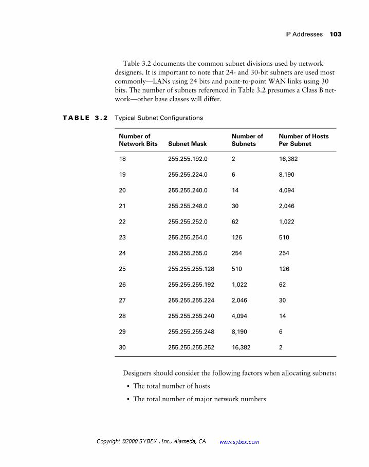
IP Addresses 103
Table 3.2 documents the common subnet divisions used by network designers. It is important to note that 24- and 30-bit subnets are used most commonly—LANs using 24 bits and point-to-point WAN links using 30 bits. The number of subnets referenced in Table 3.2 presumes a Class B net-work—other base classes will differ.
Designers should consider the following factors when allocating subnets:
� The total number of hosts
� The total number of major network numbers
T A B L E 3 . 2 Typical Subnet Configurations
Number of
Network Bits Subnet Mask
Number of
Subnets
Number of Hosts
Per Subnet
18 255.255.192.0 2 16,382
19 255.255.224.0 6 8,190
20 255.255.240.0 14 4,094
21 255.255.248.0 30 2,046
22 255.255.252.0 62 1,022
23 255.255.254.0 126 510
24 255.255.255.0 254 254
25 255.255.255.128 510 126
26 255.255.255.192 1,022 62
27 255.255.255.224 2,046 30
28 255.255.255.240 4,094 14
29 255.255.255.248 8,190 6
30 255.255.255.252 16,382 2
104 Chapter 3 � TCP/IP Network Design
� The allocation of hosts
� The number of point-to-point links
� The number of extranet and secure segments
� The availability of VLSM-aware protocols
� The need for non-VLSM subnets to remain contiguous
� The use of static routes and distribution lists to control routes
� The use of public and private address space
� The desire to summarize addresses at the distribution or access layers
Network masks may be written in various formats. The mask 255.255.255.0 may be written as /24, to reflect the number of ones in the mask.
Address Assignments
Today, network design requires a thorough understanding of TCP/IP addressing in order to be successful. Most of this requirement is facilitated by the explosive growth of the Internet (and its use of the IP protocol); however, the IP protocol also scales well, which generates benefits when it is used in the private network.
Unlike AppleTalk and IPX, IP addressing and routing benefits from sum-marization and other design criteria that are not available in the other pro-tocols’ addressing schemas. IP permits efficient and logical addressing based on various criteria—unfortunately, most current networks evolved, rather than planned, their addressing schemes, effectively negating any benefits that may have been available from the protocol itself.
The design of IP addresses in the network requires the organization to make a number of decisions. These decisions concern:
� The use of public or private address space
� The use of variable-length subnet masks
� The use of address summarization
� The use of automatic address assignment
Public and Private Addresses 105
� The existence of addresses already in the network
� The translation of addresses
Designers are also typically responsible for allocating addresses in DHCP pools—a mechanism that permits dynamic addressing in IP networks. This greatly simplifies the administration requirements at the workstation and is covered in greater detail in Chapter 7.
One of the keys to a strong network design is the use of consistent addresses in the network. For example, most designers allocate a block of addresses for network devices at the beginning or end of the address range. This arrange-ment accomplishes two goals: First, the identification of a device is greatly simplified, and second, access lists and other security mechanisms can be defined consistently.
Public and Private Addresses
The Internet connects a wide array of networks, with each requiring a methodology of uniquely identifying each device in the network. As such a methodology, IP addresses must be unique between devices.
Unlike the burned-in address (MAC) found on a network adapter, the IP address is assigned and is used to create a logical confederation of devices. These groupings are then used to distribute information to other devices in the network. This scenario is typically referred to as routing.
The IP address itself is likely familiar to most readers, so just consider the following as beneficial review. IP addresses, in version 4, are 32-bit values written in dotted decimal notation. For example, an IP address might appear as 10.100.100.9. This address must be unique within the network, and the address may be assigned either manually or dynamically via a process such as DHCP.
All devices contain an address (subnet) mask in addition to the IP address. This mask is applied to the address to identify the scope of the logical group-ing. The mask is also 32 bits long.
Consider that the designer wishes to create a medium-sized IP network. The mask could be 255.255.255.0, which when applied to the address 10.100.100.9 yields a grouping of 256 addresses. The first address and the last are reserved, and the resulting mask permits 254 hosts. Note that the network portion of the address was defined by the ones portion of the mask—the 255 decimal notation. The zero notation signified eight zero bits, or the number of unique hosts within that network—equal to the same dec-imal number as two to the eighth power. In the same manner, the designer
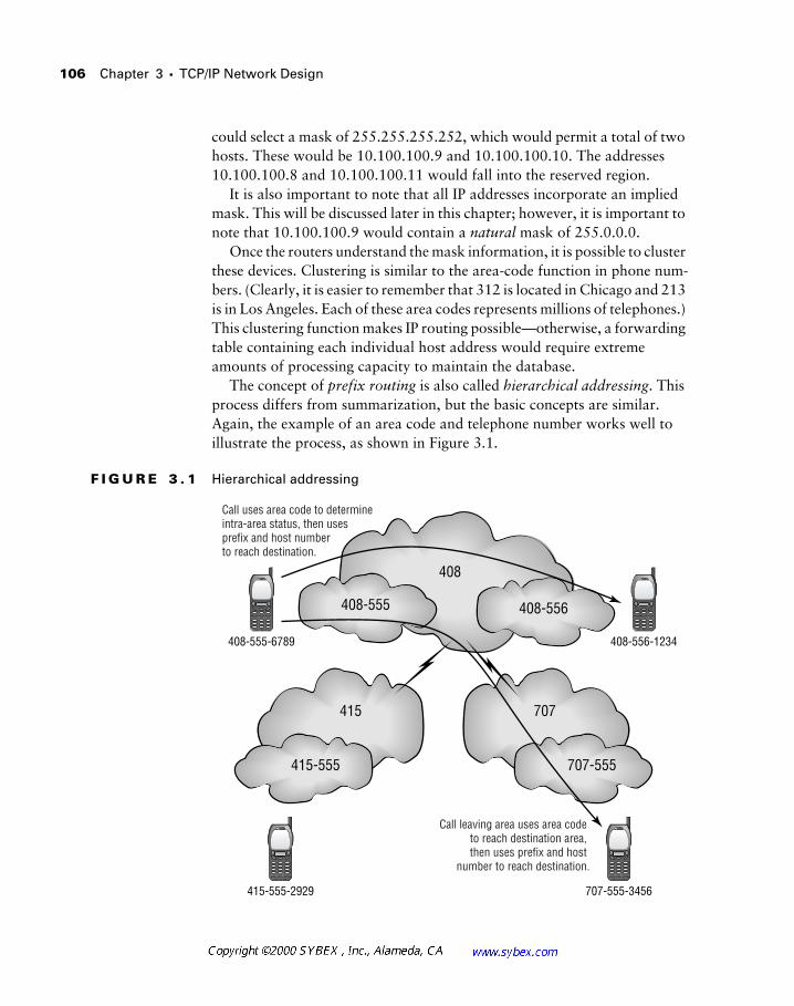
106 Chapter 3 � TCP/IP Network Design
could select a mask of 255.255.255.252, which would permit a total of two hosts. These would be 10.100.100.9 and 10.100.100.10. The addresses 10.100.100.8 and 10.100.100.11 would fall into the reserved region.
It is also important to note that all IP addresses incorporate an implied mask. This will be discussed later in this chapter; however, it is important to note that 10.100.100.9 would contain a natural mask of 255.0.0.0.
Once the routers understand the mask information, it is possible to cluster these devices. Clustering is similar to the area-code function in phone num-bers. (Clearly, it is easier to remember that 312 is located in Chicago and 213 is in Los Angeles. Each of these area codes represents millions of telephones.) This clustering function makes IP routing possible—otherwise, a forwarding table containing each individual host address would require extreme amounts of processing capacity to maintain the database.
The concept of prefix routing is also called hierarchical addressing. This process differs from summarization, but the basic concepts are similar. Again, the example of an area code and telephone number works well to illustrate the process, as shown in Figure 3.1.
F I G U R E 3 . 1 Hierarchical addressing
707-555415-555
707
408-555-6789 408-556-1234
415-555-2929 707-555-3456
408
408-555 408-556
415
Call uses area code to determine intra-area status, then uses prefix and host number to reach destination.
Call leaving area uses area code to reach destination area, then uses prefix and host
number to reach destination.
Public and Private Addresses 107
Designers should note that traditional classful routing would typically combine the area code and prefix numbers in route determination. Address assignments making use of summarization more closely mirror the telephone company model—using the area code to reach an area and then using the prefix, followed by the host number.
In addition to assigning an address and network, the designer must also choose which addresses to use. There are four possible methods for accom-plishing this:
� Use legal, public addresses assigned to the Internet Service Provider (ISP).
� Use legal, public addresses assigned to the organization.
� Use legal, public addresses that belong to another organization—a choice that precludes full connectivity to the Internet.
� Use private addresses that do not propagate across the Internet.
Private Addresses—RFC 1918/RFC 1597
RFC 1918, one of the most-used RFCs (requests for comments), defines the private, reserved IP address space. Addresses in this space can be quite con-venient, as the designer need not register with any authority. In addition, addresses assigned by the ISP belong to the ISP—should the corporation wish to change providers, it will also need to readdress all its devices.
RFC 1918 replaced RFC 1597; however, each basically defines the same policy. Under these RFCs, the public Internet will never assign or transport specific blocks of addresses, which are thus reserved for the private use of organizations. These addresses are shown in Table 3.3.
T A B L E 3 . 3 RFC 1918 Addresses
Address Available Allocation
10.0.0.0 1 Class A network
172.16.0.0 through 172.31.0.0 16 Class B networks
192.168.0.0 through 192.168.255.0 255 Class C networks
108 Chapter 3 � TCP/IP Network Design
This presentation will focus on IP v4. Designers should consider IP v6, a newer addressing scheme that uses 128 bits.
These address ranges provide the designer with an allocation in each of the IP classes—Classes A, B, and C, which will be defined in greater detail later in this chapter. The primary advantage to this approach is that the designer may assign addresses based on Class A or B address space. This option rarely exists for most small and medium-sized organizations.
Another advantage to RFC 1918 addresses is that they imply a degree of security. If the address cannot be routed on the Internet, it is very difficult for a remote attacker to reach the internal network. This is clearly oversimpli-fied, as it would likewise be impossible for the internal devices to reach legal addresses on the Internet. Actually, designers use proxies, or devices that represent the internal network resources, in order to reach the public Inter-net. These proxies typically present themselves in firewalls; however, it is possible to translate only the address information or provide non-secure proxy services. The translation of address information is called NAT, or net-work address translation, which is presented in Chapter 11.
Public Addresses
Differing from the private addresses, public addresses are assigned and unique throughout the Internet. Unfortunately, under IP v4 and the methods used to assign addresses, there is a shortage of address space, especially in the larger network allocations—Classes A and B.
There should be little surprise that the advantages of RFC 1918 addresses are the disadvantages of public addresses, given the binary nature of select-ing public or private address space. The corollary is also true.
The most significant negative of private addresses is that they are private. Anyone in any company can select any of them to use as they see fit. Some would argue that the benefits of returning IP addresses to the public pool to address the negatives are worth the complexities, including address transla-tion and proxying Internet connections. However, consider the impact when two corporations not using RFC 1918 addresses merge in the context of the following:
� NAT and proxies are not needed.
� Protocols that do not support NAT, including NetBIOS, can traverse the network without difficulty.
The Function of the Router 109
� Designers are assured that their addresses are unique. This may become an issue following the merger of two companies that selected addresses under RFC 1918.
� Troubleshooting is simplified because Layer 3 addresses do not change during a host-to-host connection.
When corporations merge, they ultimately will merge data centers and resources to reduce operating costs. This will typically require readdressing for at least one of the two merged organizations if there is overlap. In addi-tion, it is atypical for two design teams to allocate addresses exactly the same way. For example, architect one may place routers at the top of the address range, while architect two may prefer the bottom. Both ways are valid, but upon integration this minor difference may cause problems for support staffs and administrators.
The Function of the Router
The router is designed to isolate the broadcast domain and divide net-works on logical boundaries—a function of the OSI model’s Layer 3. This differs from switches and bridges, which operate at Layer 2, and repeaters and hubs, which operate at Layer 1.
Today’s routers provide many additional features for the network archi-tect, including security, encryption, and service quality. However, the role of the router remains unchanged—to forward packets based on logical addresses. In network design, this is considered routing.
Routing
The router provides two different functions in the network beyond the sim-ple isolation of the broadcast domain. First, the router is responsible for determining paths for packets to traverse. This function is addressed by the routing protocol in use and is considered overhead. The dynamic updates between routers are part of this function.
The second function of the router is packet switching. This is the act of forwarding a packet based upon the path-determination process. Switching encompasses the following:
� Entry of the packet into the router.
110 Chapter 3 � TCP/IP Network Design
� Obtaining the address information that will be needed for forwarding the packet. (In ATM, or Asynchronous Transfer Mode, it is the cell’s VPI/VCI, or virtual path identifier/virtual channel identifier.)
� Determining the destination based on the address information.
� Modifying the header and checksum information as necessary.
� Transmitting the packet/frame/cell toward its destination.
While the router may also handle additional services, this list describes the functional steps required by the forwarding process. In addition to the for-warding of packets based on the Layer 3 logical address, the router is also required to determine the routes to those destinations—a process that relies on the administrative distance function described in the next section. How-ever, routing, or more accurately, administration of the router, requires designers to consider many factors. Addressing, routing protocols, access lists, encryption, route maps (manipulation of the routing tables), and router security will only demand more attention in future years. Paths will also incorporate mobile IP and VPN (Virtual Private Network) technologies as the concept of an 80/20 rule migrates through 20/80 and toward 2/98. This means that virtually no traffic will remain local to the subnet, and as a result, the demands on administrators to work with other service providers will also increase.
If the router does not have a local interface in the major network and it receives a routing update with a classful protocol, the router will presume the natural mask. The natural mask for Class A is 255.0.0.0; for Class B it is 255.255.0.0; and for Class C it is 255.255.255.0. Readers should make sure that they understand how to identify an address’ class and what the natural mask would be before continuing. This subject is covered in greater detail in the CCNA and ICRC preparation materials.
Administrative Distance
A router performs its function by determining the best method to reach a destination—a function that relies on the routing table and metrics. Metrics will be reviewed in greater detail in Chapter 4, but for now the metric of hops used in the IP RIP protocol will be our basis. You may recall that IP RIP adds a hop to each route when it passes through a router. Therefore, a source router can compare two or more routes to the same destination and typically presumes that the lowest hop count determined by the routing protocol will
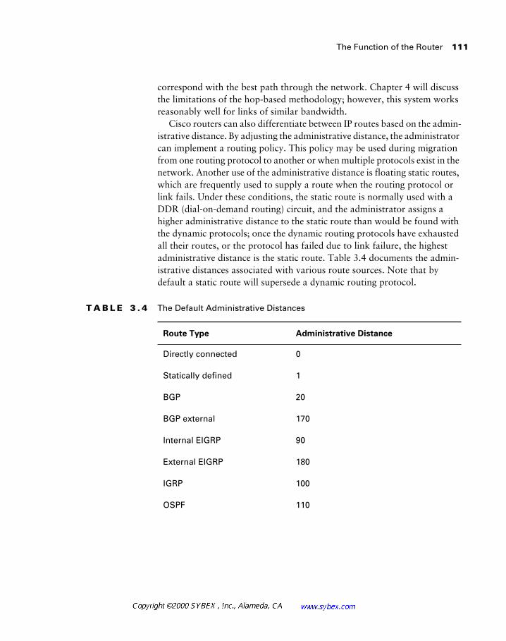
The Function of the Router 111
correspond with the best path through the network. Chapter 4 will discuss the limitations of the hop-based methodology; however, this system works reasonably well for links of similar bandwidth.
Cisco routers can also differentiate between IP routes based on the admin-istrative distance. By adjusting the administrative distance, the administrator can implement a routing policy. This policy may be used during migration from one routing protocol to another or when multiple protocols exist in the network. Another use of the administrative distance is floating static routes, which are frequently used to supply a route when the routing protocol or link fails. Under these conditions, the static route is normally used with a DDR (dial-on-demand routing) circuit, and the administrator assigns a higher administrative distance to the static route than would be found with the dynamic protocols; once the dynamic routing protocols have exhausted all their routes, or the protocol has failed due to link failure, the highest administrative distance is the static route. Table 3.4 documents the admin-istrative distances associated with various route sources. Note that by default a static route will supersede a dynamic routing protocol.
T A B L E 3 . 4 The Default Administrative Distances
Route Type Administrative Distance
Directly connected 0
Statically defined 1
BGP 20
BGP external 170
Internal EIGRP 90
External EIGRP 180
IGRP 100
OSPF 110
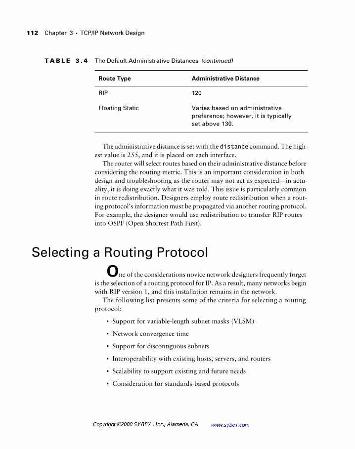
112 Chapter 3 � TCP/IP Network Design
The administrative distance is set with the distance command. The high-est value is 255, and it is placed on each interface.
The router will select routes based on their administrative distance before considering the routing metric. This is an important consideration in both design and troubleshooting as the router may not act as expected—in actu-ality, it is doing exactly what it was told. This issue is particularly common in route redistribution. Designers employ route redistribution when a rout-ing protocol’s information must be propagated via another routing protocol. For example, the designer would use redistribution to transfer RIP routes into OSPF (Open Shortest Path First).
Selecting a Routing Protocol
One of the considerations novice network designers frequently forget is the selection of a routing protocol for IP. As a result, many networks begin with RIP version 1, and this installation remains in the network.
The following list presents some of the criteria for selecting a routing protocol:
� Support for variable-length subnet masks (VLSM)
� Network convergence time
� Support for discontiguous subnets
� Interoperability with existing hosts, servers, and routers
� Scalability to support existing and future needs
� Consideration for standards-based protocols
RIP 120
Floating Static Varies based on administrative preference; however, it is typically set above 130.
T A B L E 3 . 4 The Default Administrative Distances (continued)
Route Type Administrative Distance
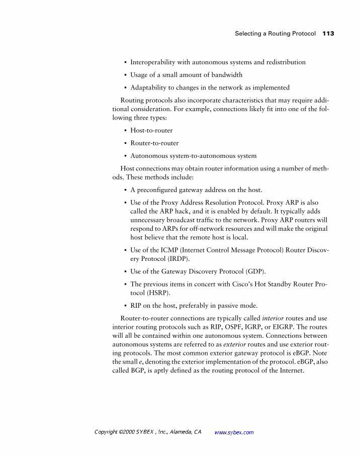
Selecting a Routing Protocol 113
� Interoperability with autonomous systems and redistribution
� Usage of a small amount of bandwidth
� Adaptability to changes in the network as implemented
Routing protocols also incorporate characteristics that may require addi-tional consideration. For example, connections likely fit into one of the fol-lowing three types:
� Host-to-router
� Router-to-router
� Autonomous system-to-autonomous system
Host connections may obtain router information using a number of meth-ods. These methods include:
� A preconfigured gateway address on the host.
� Use of the Proxy Address Resolution Protocol. Proxy ARP is also called the ARP hack, and it is enabled by default. It typically adds unnecessary broadcast traffic to the network. Proxy ARP routers will respond to ARPs for off-network resources and will make the original host believe that the remote host is local.
� Use of the ICMP (Internet Control Message Protocol) Router Discov-ery Protocol (IRDP).
� Use of the Gateway Discovery Protocol (GDP).
� The previous items in concert with Cisco’s Hot Standby Router Pro-tocol (HSRP).
� RIP on the host, preferably in passive mode.
Router-to-router connections are typically called interior routes and use interior routing protocols such as RIP, OSPF, IGRP, or EIGRP. The routes will all be contained within one autonomous system. Connections between autonomous systems are referred to as exterior routes and use exterior rout-ing protocols. The most common exterior gateway protocol is eBGP. Note the small e, denoting the exterior implementation of the protocol. eBGP, also called BGP, is aptly defined as the routing protocol of the Internet.
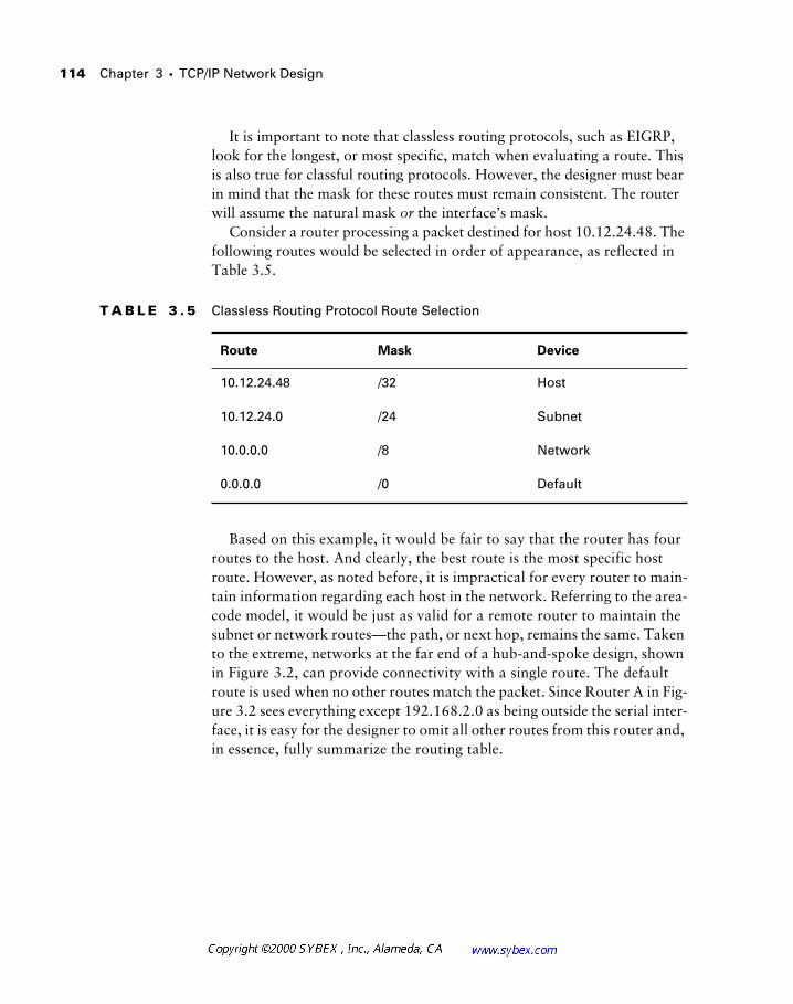
114 Chapter 3 � TCP/IP Network Design
It is important to note that classless routing protocols, such as EIGRP, look for the longest, or most specific, match when evaluating a route. This is also true for classful routing protocols. However, the designer must bear in mind that the mask for these routes must remain consistent. The router will assume the natural mask or the interface’s mask.
Consider a router processing a packet destined for host 10.12.24.48. The following routes would be selected in order of appearance, as reflected in Table 3.5.
Based on this example, it would be fair to say that the router has four routes to the host. And clearly, the best route is the most specific host route. However, as noted before, it is impractical for every router to main-tain information regarding each host in the network. Referring to the area-code model, it would be just as valid for a remote router to maintain the subnet or network routes—the path, or next hop, remains the same. Taken to the extreme, networks at the far end of a hub-and-spoke design, shown in Figure 3.2, can provide connectivity with a single route. The default route is used when no other routes match the packet. Since Router A in Fig-ure 3.2 sees everything except 192.168.2.0 as being outside the serial inter-face, it is easy for the designer to omit all other routes from this router and, in essence, fully summarize the routing table.
T A B L E 3 . 5 Classless Routing Protocol Route Selection
Route Mask Device
10.12.24.48 /32 Host
10.12.24.0 /24 Subnet
10.0.0.0 /8 Network
0.0.0.0 /0 Default
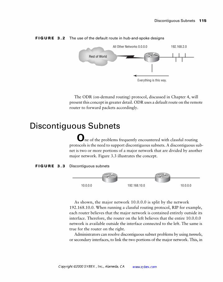
Discontiguous Subnets 115
F I G U R E 3 . 2 The use of the default route in hub-and-spoke designs
The ODR (on-demand routing) protocol, discussed in Chapter 4, will present this concept in greater detail. ODR uses a default route on the remote router to forward packets accordingly.
Discontiguous Subnets
One of the problems frequently encountered with classful routing protocols is the need to support discontiguous subnets. A discontiguous sub-net is two or more portions of a major network that are divided by another major network. Figure 3.3 illustrates the concept.
F I G U R E 3 . 3 Discontiguous subnets
As shown, the major network 10.0.0.0 is split by the network 192.168.10.0. When running a classful routing protocol, RIP for example, each router believes that the major network is contained entirely outside its interface. Therefore, the router on the left believes that the entire 10.0.0.0 network is available outside the interface connected to the left. The same is true for the router on the right.
Administrators can resolve discontiguous subnet problems by using tunnels, or secondary interfaces, to link the two portions of the major network. This, in
192.168.2.0All Other Networks 0.0.0.0
Everything is this way.
Rest of World
10.0.0.010.0.0.0 192.168.10.0
116 Chapter 3 � TCP/IP Network Design
effect, makes the two networks contiguous. A better solution is to use a classless routing protocol that can summarize and accurately maintain information regarding the two halves of the network. This also avails VLSM and other fea-tures to the network and typically simplifies administration.
Discontiguous networks can be addressed with static mappings and other techniques; however, this can lead to black holes. This concept is presented in Chapter 13; briefly however, a black hole may leave a network unreach-able under various failure scenarios.
Address Summarization
Address summarization provides a powerful function in IP networks. Under normal circumstances, each subnet would require a routing entry on every router in order to get packets to their destination. Thus, a collection of 32 subnets would require 32 routes on every router.
However, the router is concerned only with the path to the destination. As noted previously, a single default route could provide this path. While this configuration seriously limits redundancy and scalability in the network, it is a reasonable solution.
The compromise approach incorporates address summarization. Summa-rization can present hundreds of routes as a single entry in the routing table. This reduces memory demands and can prevent the need to recalculate a route should only a portion of the summarized network fail. For example, if 10.0.0.0 is available only via the FDDI (Fiber Distributed Date Interface) ring, it makes little difference if 10.12.24.0 is unavailable because the admin-istrator shut down its interface.
Consider the following block of network addresses:
� 192.168.4.0
� 192.168.5.0
� 192.168.6.0
� 192.168.7.0
Each of these addresses would typically be deployed with the natural Class C mask—255.255.255.0. This would result in four route entries and
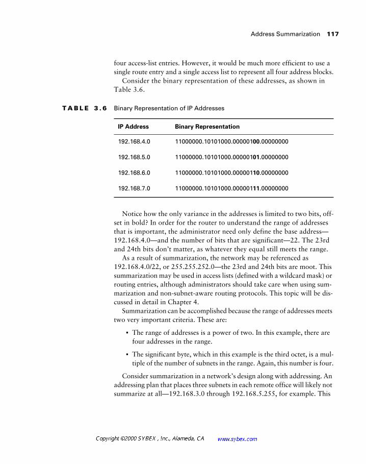
Address Summarization 117
four access-list entries. However, it would be much more efficient to use a single route entry and a single access list to represent all four address blocks.
Consider the binary representation of these addresses, as shown in Table 3.6.
Notice how the only variance in the addresses is limited to two bits, off-set in bold? In order for the router to understand the range of addresses that is important, the administrator need only define the base address—192.168.4.0—and the number of bits that are significant—22. The 23rd and 24th bits don’t matter, as whatever they equal still meets the range.
As a result of summarization, the network may be referenced as 192.168.4.0/22, or 255.255.252.0—the 23rd and 24th bits are moot. This summarization may be used in access lists (defined with a wildcard mask) or routing entries, although administrators should take care when using sum-marization and non-subnet-aware routing protocols. This topic will be dis-cussed in detail in Chapter 4.
Summarization can be accomplished because the range of addresses meets two very important criteria. These are:
� The range of addresses is a power of two. In this example, there are four addresses in the range.
� The significant byte, which in this example is the third octet, is a mul-tiple of the number of subnets in the range. Again, this number is four.
Consider summarization in a network’s design along with addressing. An addressing plan that places three subnets in each remote office will likely not summarize at all—192.168.3.0 through 192.168.5.255, for example. This
T A B L E 3 . 6 Binary Representation of IP Addresses
IP Address Binary Representation
192.168.4.0 11000000.10101000.00000100.00000000
192.168.5.0 11000000.10101000.00000101.00000000
192.168.6.0 11000000.10101000.00000110.00000000
192.168.7.0 11000000.10101000.00000111.00000000
118 Chapter 3 � TCP/IP Network Design
leads to inefficiencies that are too important to ignore if the network is to scale, and as a result it is generally preferable to skip addresses in the assign-ment process so that each range provides for growth and evenness. It is not uncommon to assign eight 254-host networks to a fairly small office, although it is practical to do so only when using RFC 1918 address space.
Beyond the academic presentation of summarization, designers will find in subsequent chapters and their designs that summarization is imperative to the configuration of a hierarchical network. Without effective summariza-tion, the network cannot scale and becomes difficult to administer.
Load Balancing in IP
The router’s physical design and its interfaces allow for a variety of switching processes on the router. This frees up the processor to focus on other tasks, instead of looking up the source and destination information for every packet that enters the router. Network designers should consider the options available to them in the processing of IP packets at Layer 3. This sec-tion will define and contrast the various methods Cisco routers use to handle forwarding.
Process Switching
Process switching is the slowest and most processor-intensive of the routing types. When a packet arrives on an interface to be forwarded, it is copied to the router’s process buffer, and the router performs a lookup on the Layer 3 address. Using the route table, an exit interface is associated with the desti-nation address. The processor encapsulates and forwards the packet with the new information to the exit interface. Subsequent packets bound for the same destination address follow the same path as the first packet.
The repeated lookups performed by the router’s processor and the pro-cessor’s relatively slow performance eventually create a bottleneck and greatly reduce the capacity of the router. This becomes even more significant as the bandwidth and number of interfaces increase and as the routing pro-tocols demand more processor resources.
Load Balancing in IP 119
Fast Switching
Fast switching is an improvement over process switching. The first packet of a new session is copied to the interface processor buffer. The packet is then copied to the CxBus (or other backplane technology as appropriate to the platform) and sent to the switch processor. A check is made against other switching caches (for example, silicon or autonomous) for an existing entry.
Fast switching is then used because no entries exist within the more effi-cient caches. The packet header is copied and sent to the route processor, where the fast-switching cache resides. Assuming that an entry exists in the cache, the packet is encapsulated for fast switching and sent back to the switch processor. Then the packet is copied to the buffer on the outgoing interface processor, and ultimately it is sent out the destination interface.
Fast switching is on by default for lower-end routers like the 4000/2500 series and may be used on higher-end routers as well. It is important to note that diagnostic processes sometimes require reverting to process switching. Fast-switched packets will not traverse the route processor, which provides the method by which packets are displayed during debugging. Fast switching may also be inappropriate when bringing traffic from high-speed interfaces to slower ones—this is one area where designers must understand not only the bandwidth potential of their links, but also the actual flow of traffic.
Fast switching guarantees that packets will be processed within 16 pro-cessor cycles. Unlike process-switched packets, the router’s processor will not be interrupted to facilitate forwarding.
Autonomous Switching
Autonomous switching is comparable to fast switching. When a packet arrives on the interface processor, it checks the switching cache closest to it—the caches that reside on other processor boards. The packet is encapsulated for autonomous switching and sent back to the interface processor. The packet header is not sent to the route processor. Autonomous switching is available only on AGS+ and Cisco 7000 series routers that have high-speed controller interface cards.
Silicon Switching
Silicon switching is available only on the Cisco 7000 with an SSP (Silicon Switch Processor). Silicon-switched packets are compared to the silicon-switching cache
120 Chapter 3 � TCP/IP Network Design
on the SSE (Silicon Switching Engine). The SSP is a dedicated switch processor that offloads the switching process from the route processor, providing a fast-switching solution. Designers should note that packets must still traverse the backplane of the router to get to the SSP, and then return to the exit interface. NetFlow switching (defined below) and multilayer switching are more efficient than silicon switching.
Optimum Switching
Optimum switching follows the same procedure as the other switching algorithms. When a new packet enters the interface, it is compared to the optimum-switching cache, rewritten, and sent to the chosen exit interface. Other packets associated with the same session then follow the same path. All processing is carried out on the interface processor, including the CRC (cyclical redundancy check). Optimum switching is faster than both fast switching and NetFlow switching, unless you have implemented several access lists.
Optimum switching replaces fast switching on high-end routers. As with fast switching, optimum switching must be turned off in order to view pack-ets while troubleshooting a network problem. Optimum switching is the default on 7200 and 7500 routers.
Distributed Switching
Distributed switching occurs on the VIP (Versatile Interface Processor) cards, which have a switching processor onboard, so it’s very efficient. All required processing is done right on the VIP processor, which maintains a copy of the router’s routing cache. With this arrangement, even the first packet needn’t be sent to the route processor to initialize the switching path, as it must with the other switching algorithms. Router efficiency increases as more VIP cards are added.
It is important to note that access lists cannot be accommodated with dis-tributed switching.
NetFlow Switching
NetFlow switching is both an administrative tool and a performance-enhancement tool that provides support for access lists while increasing the volume of packets that can be forwarded per second. It collects detailed data
Load Balancing in IP 121
for use with circuit accounting and application-utilization information. Because of all the additional data that NetFlow collects (and may export), expect an increase in router overhead—possibly as much as a five-percent increase in CPU utilization.
NetFlow switching can be configured on most interface types and can be used in a switched environment. ATM, LAN, and VLAN (virtual LAN) tech-nologies all support NetFlow switching.
NetFlow switching does much more than just switching—it also gathers statistical data, including protocol, port, and user information. All of this is stored in the NetFlow switching cache, according to the individual flow that’s defined by the packet information (destination address, source address, protocol, source and destination port, and incoming interface).
The data can be sent to a network management station to be stored and processed. The NetFlow switching process is very efficient: An incoming packet is processed by the fast- or optimum-switching process, and then all path and packet information is copied to the NetFlow cache. The remaining packets that belong to the flow are compared to the NetFlow cache and for-warded accordingly.
The first packet that’s copied to the NetFlow cache contains all security and routing information, and if an access list is applied to an interface, the first packet is matched against it. If it matches the access-list criteria, the cache is flagged so that the remaining packets in the flow can be switched without being compared to the list. (This is very effective when a large amount of access-list processing is required.)
NetFlow switching can also be configured on VIP interfaces. For each of these forwarding processes, designers should consider the
impact of access lists. At present, NetFlow typically provides the best per-formance when access lists are needed. A recent study mentioned in an article by Peter Morrissey in Network Computing demonstrated a 700 percent per-formance benefit when using NetFlow and a 200-line access list. Perfor-mance benefits are lower with shorter lists; however, with anything beyond a single-line access list, NetFlow will yield better performance than optimal switching.
Cisco Express Forwarding
Cisco Express Forwarding (CEF) is a switching function, designed for high-end backbone routers. It functions on Layer 3 of the OSI model, and its big-gest asset is the capability to remain stable in a large network. However, it’s
122 Chapter 3 � TCP/IP Network Design
also more efficient than both the fast- and optimum-switching defaults. CEF is wonderfully stable in large environments because it doesn’t rely on cached information. Instead of using a CEF cache, it refers to the Forwarding Infor-mation Base (FIB), which consists of information duplicated from the IP route table. Every time the routing information changes, the changes are propagated to the FIB. Thus, instead of comparing old cache information, a packet looks to the FIB for its forwarding information.
CEF stores the Layer 2 MAC addresses of connected routers (or next-hop) in the adjacency table. Even though CEF features advanced capabilities, you should consider several restrictions before implementing CEF on a router. According to the document “Cisco Express Forwarding,” available from the Cisco Web page Cisco Connection Online, system requirements are quite high. The processor should have at least 128MB of RAM, and the line cards should have 32MB each. CEF takes the place of VIP distributed- and fast-switching on VIP interfaces. The following features aren’t supported by CEF:
� ATM DXI
� Token Ring
� Multipoint PPP
� Access lists on the GSR (Giga Switch Router)
� Policy routing
� NAT
� SMDS
Nevertheless, CEF does many things—even load balancing is possible through the FIB. If there are multiple paths to the same destination, the IP route table knows about them all. This information is also copied to the FIB, which CEF consults for its switching decisions.
Load balancing can be configured in two different modes. The first mode is load balancing based on the destination (called per-destination load balancing); the second mode is based on the packet (called per-packet load balancing). Per-destination load balancing is on by default and must be turned off to enable per-packet load balancing.
Accounting may also be configured for CEF, which furnishes you with detailed statistics about CEF traffic. You can make two specifications when collecting CEF statistics:
Summary 123
� To collect information on traffic that’s forwarded to a specific destination
� To collect statistics for traffic that’s forwarded through a specific destination
CEF was designed for large networks—if reliable and redundant switch-ing paths are necessary, CEF is certainly preferred. However, there are sig-nificant hardware requirements, and some Cisco IOS features may not be available.
Cisco routers may support concurrent load balancing when routing IP. However, this feature is dependent on the switching mechanism in use. Up to six paths may be balanced in the current releases of the IOS, dependent on the routing protocol in use.
Autonomous and silicon switching have been updated with optimum, distrib-uted, and NetFlow. However, from a load-balancing perspective, they operate in the same manner as their replacements. Autonomous and silicon-switched packets will be load-balanced by destination.
Summary
This chapter presented a wide array of material on the IP protocol and on some of the criteria for selecting an IP routing protocol. The next chapter will build upon this material and provide greater depth regarding the options available to designers regarding IP routing protocols.
Readers should feel comfortable with the following concepts:
� IP address structures
� IP address classes
� IP address summarization
� The implications of RFC 1918/RFC 1597
� The methods used by the router to forward packets
124 Chapter 3 � TCP/IP Network Design
� The role of the router and its additional features
� The problems associated with discontiguous subnets and the benefits of VLSM-aware protocols
Designers should also be prepared to integrate this material into the fol-lowing chapter, which details the IP routing protocols, and subsequent ones, which address non-IP-based protocols and the issues that confront designers in typical networks.
Review Questions 125
Review Questions
1. Which of the following are methods used to assign IP addresses?
A. Manual configuration
B. WINS
C. DHCP
D. BootP
E. NFS
2. The designer’s major issues when designing for IP networks are:
A. Routing
B. Addressing
C. Security
D. Naming
E. All of the above
3. When selecting a routing protocol, the designer would NOT consider which of the following?
A. Convergence time
B. Addressing flexibility
C. CDP packets
D. Support across vendors/platforms
E. Resource utilization
F. Topology of the network
126 Chapter 3 � TCP/IP Network Design
4. Which of the following would be reasons to summarize routes?
A. Reduction in the size of the routing table
B. Increase in the size of the routing table
C. Redundancy
D. Load balancing
5. The designer configures the network to present the routes from the distribution layer to the core as 10.11.0.0/16. This is an example of:
A. DHCP
B. Route summarization
C. BootP
D. CDP
6. To support VLSM and route summarization, a routing protocol must be:
A. Classful
B. Classless
C. Dynamic
D. Enhanced
7. A classful routing protocol will:
A. Not support VLSM
B. Route on the first octet bits and their significance
C. Not include subnet information in routing updates
D. All of the above
E. None of the above
Review Questions 127
8. A classless routing protocol will:
A. Not support VLSM
B. Route on the first octet bits and their significance
C. Not include subnet information in routing updates
D. All of the above
E. None of the above
9. The natural mask for address 148.241.14.56 would be which of the following?
A. 255.0.0.0
B. 255.255.0.0
C. 255.255.255.0
D. Cannot be determined with the information provided
10. A routing update using a classful routing protocol (assuming no net-work member interfaces on the receiving router) for 10.11.1.0/24 would appear as which of the following?
A. 10.0.0.0
B. 10.11.0.0
C. 10.11.1.0
D. Cannot be determined with the information provided.
11. The summary address 192.168.8.0/22 represents:
A. 192.168.0.0 to 192.168.7.255
B. 192.168.0.0 to 192.168.255.255
C. 192.168.8.0 to 192.168.11.255
D. Class C address space cannot be summarized

128 Chapter 3 � TCP/IP Network Design
12. Which summarization best covers 162.15.4.0 through 162.15.7.0?
A. 162.15.7.0/24
B. 162.15.7.0/22
C. 162.15.0.0.22
D. 162.15.4.0/22
13. To summarize the addresses from 162.110.84.0 to 162.110.87.255, the designer would best use:
A. 162.110.87.0 255.255.252.0
B. 162.110.84.0 255.255.255.0
C. 162.110.87.255 255.255.255.255
D. 162.110.84.0 255.255.252.0
14. The address 121.45.11.40 is:
A. Class A
B. Class B
C. Class C
D. Class D
15. The address 127.60.80.12 is:
A. Class A
B. Class B
C. Class C
D. None of the above
16. One disadvantage of classful routing protocols, including RIP and IGRP, is:
A. All interfaces must be of the same type.
B. All interfaces must use the same network mask.
C. All interfaces must use the natural mask.
D. All interfaces must be within the same subnet.

Review Questions 129
17. Secondary interfaces do not provide:
A. A means to link discontiguous subnets
B. A method for adding hosts to a physical media
C. Trunking via ISL or 802.1q
D. Support for local routing
18. Which of the following would be the best reason to use registered pub-lic address space?
A. To avoid addressing problems should the corporation merge with another organization
B. To obtain Class C address space
C. To simplify NAT processes
D. None of the above
19. Each Class C network could support:
A. Two hosts
B. 16 hosts
C. 64 hosts
D. 254 hosts
20. Which of the following routes would the router most likely use?
A. A route to the subnet
B. A route to the host
C. A route to the network
D. A default route

130 Chapter 3 � TCP/IP Network Design
Answers to Review Questions
1. A, C, D.
DHCP and BootP are dynamic assignment methods.
2. E.
3. C.
4. A.
5. B.
6. B.
7. D.
8. E.
9. B.
10. A.
11. C.
12. D.
13. D.
14. A.
15. D.
16. B.
17. C.
18. A.
19. D.
20. B.
Chapter
4The IP Routing Protocols
CISCO INTERNETWORK DESIGN EXAM OBJECTIVES COVERED IN THIS CHAPTER:
� Choose the appropriate IP routing protocol and features based
on convergence, overhead, and topology.
� Identify IP routing pathologies and issues and how to
avoid them.
� Use modular design and summarization features to design
scalable Open Shortest Path First (OSPF) internetworks.
� Allocate IP addresses in contiguous blocks so that OSPF
summarization can be used.
� Determine IGRP convergence time for various internetwork
configurations.
� Use IGRP for path determination in IP internetworks.
� Use Enhanced IGRP for path determination in internetworks
that support IP, IPX, and AppleTalk.
With the explosive growth of the Internet, the IP protocol has become a de facto standard for virtually all networks. As such, the pro-tocol is continuing to undergo rapid development, and that development includes enhancements in terms of routing protocol features and general net-work design. This chapter will focus specifically on the IP routing protocols and how to consider each for integration into a network design.
Readers will likely note a number of recurrent themes in this presenta-tion—the features of each protocol and the convergence time characteristics. Whenever a network topology changes, it is the job of the routing protocol to reroute traffic and determine the new best paths for data flow on the inter-network. (The amount of time required to complete this process in the event of any change is referred to as convergence time.) These are two of the most significant factors in selecting a routing protocol. Additional factors include familiarity, support, and availability.
IP Routing Protocols
In the previous chapter, the Internet Protocol (IP) and the criteria for designing networks using IP were addressed. This chapter will build upon those concepts by adding the dynamic IP routing protocols including RIP, RIP version 2, IGRP, EIGRP, OSPF, ODR, BGP, and IS-IS.
Dynamic routing protocols were developed to circumvent the deficits found in static routing. This chapter will present network design with static routes, in addition to the IP routing protocols listed in Table 4.1. Please note that each of these protocols will be presented in greater detail later in this
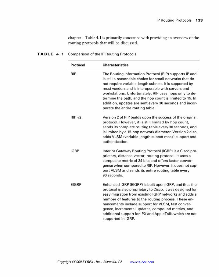
IP Routing Protocols 133
chapter—Table 4.1 is primarily concerned with providing an overview of the routing protocols that will be discussed.
T A B L E 4 . 1 Comparison of the IP Routing Protocols
Protocol Characteristics
RIP The Routing Information Protocol (RIP) supports IP and is still a reasonable choice for small networks that do not require variable-length subnets. It is supported by most vendors and is interoperable with servers and workstations. Unfortunately, RIP uses hops only to de-termine the path, and the hop count is limited to 15. In addition, updates are sent every 30 seconds and incor-porate the entire routing table.
RIP v2 Version 2 of RIP builds upon the success of the original protocol. However, it is still limited by hop count, sends its complete routing table every 30 seconds, and is limited by a 15-hop network diameter. Version 2 also adds VLSM (variable-length subnet mask) support and authentication.
IGRP Interior Gateway Routing Protocol (IGRP) is a Cisco pro-prietary, distance-vector, routing protocol. It uses a composite metric of 24 bits and offers faster conver-gence when compared to RIP. However, it does not sup-port VLSM and sends its entire routing table every 90 seconds.
EIGRP Enhanced IGRP (EIGRP) is built upon IGRP, and thus the protocol is also proprietary to Cisco. It was designed for easy migration from existing IGRP networks and adds a number of features to the routing process. These en-hancements include support for VLSM, fast conver-gence, incremental updates, compound metrics, and additional support for IPX and AppleTalk, which are not supported in IGRP.
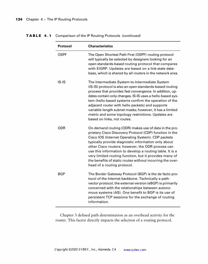
134 Chapter 4 � The IP Routing Protocols
Chapter 3 defined path determination as an overhead activity for the router. This factor directly impacts the selection of a routing protocol.
OSPF The Open Shortest Path First (OSPF) routing protocol will typically be selected by designers looking for an open standards-based routing protocol that compares with EIGRP. Updates are based on a link-state data-base, which is shared by all routers in the network area.
IS-IS The Intermediate System-to-Intermediate System (IS-IS) protocol is also an open standards-based routing process that provides fast convergence. In addition, up-dates contain only changes. IS-IS uses a hello-based sys-tem (hello-based systems confirm the operation of the adjacent router with hello packets) and supports variable-length subnet masks; however, it has a limited metric and some topology restrictions. Updates are based on links, not routes.
ODR On-demand routing (ODR) makes use of data in the pro-prietary Cisco Discovery Protocol (CDP) function in the Cisco IOS (Internet Operating System). CDP packets typically provide diagnostic information only about other Cisco routers; however, the ODR process can use this information to develop a routing table. It is a very limited routing function, but it provides many of the benefits of static routes without incurring the over-head of a routing protocol.
BGP The Border Gateway Protocol (BGP) is the de facto pro-tocol of the Internet backbone. Technically a path-vector protocol, the external version (eBGP) is primarily concerned with the relationships between autono-mous systems (AS). One benefit to BGP is its use of persistent TCP sessions for the exchange of routing information.
T A B L E 4 . 1 Comparison of the IP Routing Protocols (continued)
Protocol Characteristics
IP Routing Protocols 135
Designers should consider the different resources that are needed to imple-ment a routing protocol, including router CPU, router memory, link band-width, support staff familiarity, and protocol features, which include support for VLSM, summarization, and convergence.
Designers should ask themselves the following questions when selecting a routing protocol:
� Under what conditions are routing updates sent?
� This relates to timers, events, or both.
� What is transmitted during a routing update?
� Some protocols send only the changes to the routing table during an update. Other protocols send the entire routing table.
� How are routing updates propagated?
� Some routing protocols send updates and information only to adjacent neighbors, while others send information to a cluster of routers (an area) or to an autonomous system.
� How long does the convergence process take?
� The time required to converge all routing tables in the internet-work depends upon many factors. Re-convergence occurs when a path that is used suddenly becomes unavailable. Dynamic routing protocols make every effort to locate an alternative route to the destination. Some protocols, like EIGRP, calculate alternative paths before the failure, which facilitates rapid convergence. Other protocols require significant amounts of time to distribute informa-tion regarding the failure and calculate the alternative path.
Routers also combine various methods for learning routes. These meth-ods should be designed to work together to establish the most efficient rout-ing throughout the network. In addition to the technical considerations, designers should also consider cost in defining efficiency.
The router may obtain route information from any or all of the following sources:
� Connected interfaces
� Static routing entries
� Information learned from dynamic routing protocols
136 Chapter 4 � The IP Routing Protocols
� Redistribution between routing protocols
� ARP, Inverse ARP, and ICMP redirects
� Manipulation of the previous methods via access lists and other filters
Designers should also consider what methods are available to trigger fail-ure updates. Local interfaces can be detected via keepalives, including ATM OAM (operation, administration, and maintenance) cells, and the carrier-detect lead.
Network Design with Static Routing
Before presenting the dynamic routing protocols, it is appropriate to provide an overview of static routes. Static routes refer in the generic to those routes that are manually entered by the network administrator into the router’s configuration file. These routes may be used in at least one of three typical situations.
� The administrator needs to define a default route for packets to leave the network.
� The administrator requires a route that takes effect upon failure of the dynamic routing process. This is called a floating-static route.
� A dynamic routing protocol is not available or desirable. This may be for security, bandwidth, or compatibility concerns. Frequently, static routes are used to reduce overhead on single-point, low-bandwidth circuits.
There are a couple of deficits with static routes, however. First, the routes are static—as the name suggests. This means that failures in the network topology cannot be detected and circumvented automatically. Second, the administrator must manually populate the routing table and maintain the entries whenever a change to the network is made.
Cisco routers automatically support proxy ARP on most interfaces. The proxy ARP function will spoof off-network resources with the router’s MAC (Media Access Control) address, and the router will take the responsibility of forwarding packets to the final end node. This behavior permits the estab-lishment of routes based on interfaces as opposed to the IP address. For example, the route may be through router 192.168.5.1, but the administra-tor can reference the route as being out interface Ethernet 0/0.
Network Design with Static Routing 137
Because of security, diagnostic, and performance concerns, it is recom-mended that administrators not use the proxy ARP function and that it be disabled on all interfaces. While it is possible to find network administrators with little or no experience with one of the more advanced dynamic routing protocols, it is very unlikely that an administrator will not have experience with static routes. This static route experience may be to define a default route off the network or to define routes in areas where a dynamic routing protocol would be undesirable, including those in secure arenas and between companies.
Static routes offer the administrator a high degree of control over the net-work and consume no bandwidth for routing updates, making them advan-tageous on limited-bandwidth or low-reliability links. So, given the benefits of static routes—familiarity, controllability, and efficiency—why would a designer choose to not use static routes?
The answer typically is that designers do use static routes and, in fact, may use them quite often in the overall network design. However, the scalability of the network is greatly limited if the entire network is designed using static routes. This chapter will address the benefits of the dynamic routing proto-cols later, but for now will define these benefits as load balancing, redun-dancy, and scalability.
Network Design in the Real World: A Production Design Consideration
Before addressing the details of each routing protocol, it is important to establish a context that brings us back to design. The specifics of each rout-ing protocol could easily consume an entire text on their own, and there are many solid treatments on each. However, for the exam objectives, it is only necessary to have a cursory understanding of each protocol—a level of detail that would be insufficient in production networks.
Therefore, this sidebar includes a scenario to illustrate a simple design chal-lenge related to the selection of a routing protocol. The deployed solution is provided, so do not consider this to be a test. Rather, review this at a high level—the specific details of each protocol are provided only as a matrix for this solution set. In your network designs, you will likely add much more detail in terms of cost, complexity, supportability, and availability.
138 Chapter 4 � The IP Routing Protocols
A large financial institution recently deployed a 70+-router network using all static routes. Clearly, it is possible to route a large number of networks using static routes; however, the design is severely limited, particularly in terms of administrative overhead. The network is a hub-and-spoke design with limited bandwidth and single routes throughout. The institution also desired that the network support different subnet masks, although the ini-tial design was based on two hosts per subnet (a /30 mask). Given these conditions, consider the choices available to the designers and whether you would agree with the solution deployed. The routing options for a hub-and-spoke network are as follows:
RIP No support for VLSM. Efficient, but consumes bandwidth.
RIP v2 Supports VLSM and is efficient, but is unfamiliar to this organiza-tion and consumes bandwidth.
OSPF While a strong choice from a number of perspectives, the design team was concerned about router CPU utilization and potential design issues should the enterprise convert to OSPF. The protocol supports VLSM and is fairly efficient regarding bandwidth utilization. Guidelines vary, but most experts recommend fewer than 50 OSPF neighbors (contrasting with EIGRP’s recommendation of 30—partly the result of memory requirements and partly the benefit of link-state protocols), so this design would be push-ing that constraint.
EIGRP While supported on the more advanced routers used for the pilot, EIGRP was not supported on the CBOS (Cisco Broadband Operating Sys-tem) routers (600 series) that were preferred for cost reasons. In addition, EIGRP isn’t well suited to hub-and-spoke designs and may have problems with low memory/CPU routers with as few as 12 neighbors. A good protocol overall, EIGRP is not well suited to this design.
IGRP IGRP would not support VLSM, and it was not supported by the CBOS routers.
Static Static routes consume no bandwidth and use a minimal amount of CPU. In addition, the use of static routes will support variable-length subnet masks (in a manner of speaking). The downside is that static routes must be configured by the administrator.
Network Design with RIP 139
Network Design with RIP
The Routing Information Protocol (RIP) is an amazing protocol. Few things in computing have lasted as long—and with as few changes (not counting RIP v2). However, IP RIP is a very limited (by today’s standards) distance-vector protocol capable of serving networks with up to 15 hops. It is classful, which means that the protocol does not include subnet mask information—therefore, route summarization and VLSM functions are not available.
In actuality, RIP and the other classful routing protocols do summarize—unfortunately, it is on the classful boundary, which was discussed in Chapter 3. Therefore, summarization with a classful protocol is typically a deterent.
RIP v2 builds upon the original RIP specification and adds a number of features, the most significant of which is the sharing of subnet mask infor-mation. Thus, RIP v2 supports VLSM. Figure 4.1 illustrates the packet for-mats for both RIP and RIP v2. Note that there are many similarities between the two in order to facilitate interoperability.
Following a review of the above material, the only viable choices were RIP v2 and static routes. RIP v2 was considered, but the number of remote con-figuration steps and the bandwidth consumption issues were sufficient to put it in second place.
Notice some of the themes used in selecting a routing protocol: link band-width, router CPU utilization, router memory, support for VLSM, redundant paths, load balancing, availability, and support staff familiarity. These will be important factors in your designs.
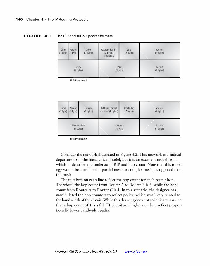
140 Chapter 4 � The IP Routing Protocols
F I G U R E 4 . 1 The RIP and RIP v2 packet formats
Consider the network illustrated in Figure 4.2. This network is a radical departure from the hierarchical model, but it is an excellent model from which to describe and understand RIP and hop count. Note that this topol-ogy would be considered a partial mesh or complex mesh, as opposed to a full mesh.
The numbers on each line reflect the hop count for each router hop. Therefore, the hop count from Router A to Router B is 3, while the hop count from Router A to Router C is 1. In this scenario, the designer has manipulated the hop counters to reflect policy, which was likely related to the bandwidth of the circuit. While this drawing does not so indicate, assume that a hop count of 1 is a full T1 circuit and higher numbers reflect propor-tionally lower bandwidth paths.
Cmd(1 byte)
Version(1 byte)
Zero(2 bytes)
Address Family(2 bytes)
IP equals 2
Zero(2 bytes)
Zero(2 bytes)
Zero(2 bytes)
IP RIP version 1
Address(4 bytes)
Metric(4 bytes)
Cmd(1 byte)
Version(1 byte)
Unused(2 bytes)
Address FormatIdentifier (2 bytes)
Route Tag(2 bytes)
Next Hop(4 bytes)
Subnet Mask(4 bytes)
IP RIP version 2
Address(4 bytes)
Metric(4 bytes)
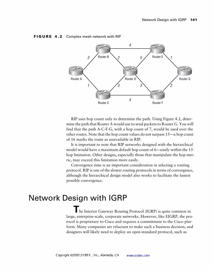
Network Design with IGRP 141
F I G U R E 4 . 2 Complex mesh network with RIP
RIP uses hop count only to determine the path. Using Figure 4.2, deter-mine the path that Router A would use to send packets to Router G. You will find that the path A-C-F-G, with a hop count of 7, would be used over the other routes. Note that the hop count values do not surpass 15—a hop count of 16 marks the route as unavailable in RIP.
It is important to note that RIP networks designed with the hierarchical model would have a maximum default hop count of 6—easily within the 15-hop limitation. Other designs, especially those that manipulate the hop met-ric, may exceed this limitation more easily.
Convergence time is an important consideration in selecting a routing protocol. RIP is one of the slower routing protocols in terms of convergence, although the hierarchical design model also works to facilitate the fastest possible convergence.
Network Design with IGRP
The Interior Gateway Routing Protocol (IGRP) is quite common in large, enterprise-scale, corporate networks. However, like EIGRP, the pro-tocol is proprietary to Cisco and requires a commitment to the Cisco plat-form. Many companies are reluctant to make such a business decision, and designers will likely need to deploy an open-standard protocol, such as
1 3 3 2
3 2
4
4
5 1
Router A
Router B
Router D
Router E
Router C Router F
Router G
142 Chapter 4 � The IP Routing Protocols
OSPF. In addition, IGRP, and its successor, EIGRP, tolerate arbitrary topol-ogies better than OSPF—however, designers should strive to follow the hier-archical model in order to improve convergence and troubleshooting.
It is unlikely that a designer would select IGRP for a completely new net-work design, but it might still be warranted for reasons that will be presented in this section. It is much more likely that the use of IGRP will be based on previous deployments of the protocol and the required integration that the network will demand. A recent Cisco survey found IGRP and EIGRP in over 50 percent of networks.
IGRP is a more advanced protocol than RIP, which it was designed to replace. It is a distance-vector protocol that uses a 24-bit metric value to determine the best route, with a maximum of 254 hops (default value of 100 hops). This is greatly enhanced over RIP’s 15-hop-based metric. Other ben-efits include load balancing and path determination, where the protocol can select from multiple default networks. IGRP is also more tolerant of non-hierarchical topologies; unlike EIGRP, IGRP can support arbitrary topology configurations. However, both protocols operate better when deployed with a strong design. It is important to note that complex mesh configurations will impact convergence in both IGRP and EIGRP, but the redundancy ben-efits of these designs may offset the negatives.
As with RIP, IGRP transmits the entire routing table with each update, which by default occurs every 90 seconds (compared to RIP at every 30 sec-onds). These updates may contain 104 route entries (within a 1,500-byte packet), which is a clear improvement over IP RIP, which includes only 25 routes. Unfortunately, the entire routing table is sent each time. Of more importance in advanced networks, IGRP does not support VLSM and is classful. Finally, IGRP uses the concept of split-horizon to prevent routing loops. By default this feature is on. However, the architect may disable it to support point-to-multipoint installations.
Some texts state that split-horizon is disabled automatically with some topol-ogies, such as SMDS. This is incorrect. You should use the show ip interface command to check the current status of an interface.
Split-horizon is used to prevent routing loops by blocking the advertise-ment of a route out the interface that it was learned from. Poison reverse is a variation on this concept that sends the route back to the source, but with an illegal metric.
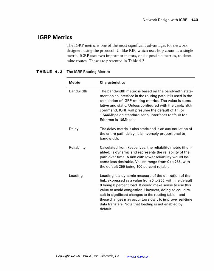
Network Design with IGRP 143
IGRP Metrics
The IGRP metric is one of the most significant advantages for network designers using the protocol. Unlike RIP, which uses hop count as a single metric, IGRP uses two important factors, of six possible metrics, to deter-mine routes. These are presented in Table 4.2.
T A B L E 4 . 2 The IGRP Routing Metrics
Metric Characteristics
Bandwidth The bandwidth metric is based on the bandwidth state-ment on an interface in the routing path. It is used in the calculation of IGRP routing metrics. The value is cumu-lative and static. Unless configured with the bandwidth command, IGRP will presume the default of T1, or 1.544Mbps on standard serial interfaces (default for Ethernet is 10Mbps).
Delay The delay metric is also static and is an accumulation of the entire path delay. It is inversely proportional to bandwidth.
Reliability Calculated from keepalives, the reliability metric (if en-abled) is dynamic and represents the reliability of the path over time. A link with lower reliability would be-come less desirable. Values range from 0 to 255, with the default 255 being 100 percent reliable.
Loading Loading is a dynamic measure of the utilization of the link, expressed as a value from 0 to 255, with the default 0 being 0 percent load. It would make sense to use this value to avoid congestion. However, doing so could re-sult in significant changes to the routing table—and these changes may occur too slowly to improve real-time data transfers. Note that loading is not enabled by default.
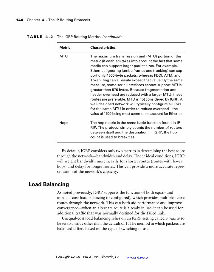
144 Chapter 4 � The IP Routing Protocols
By default, IGRP considers only two metrics in determining the best route through the network—bandwidth and delay. Under ideal conditions, IGRP will weight bandwidth more heavily for shorter routes (routes with fewer hops) and delay for longer routes. This can provide a more accurate repre-sentation of the network’s capacity.
Load Balancing
As noted previously, IGRP supports the function of both equal- and unequal-cost load balancing (if configured), which provides multiple active routes through the network. This can both aid performance and improve convergence—when an alternate route is already in use, it can be used for additional traffic that was normally destined for the failed link.
Unequal-cost load balancing relies on an IGRP setting called variance to be set to a value other than the default of 1. The method in which packets are balanced differs based on the type of switching in use.
MTU The maximum transmission unit (MTU) portion of the metric (if enabled) takes into account the fact that some media can support larger packet sizes. For example, Ethernet (ignoring jumbo frames and trunking) can sup-port only 1500-byte packets, whereas FDDI, ATM, and Token Ring can all easily exceed that value. By the same measure, some serial interfaces cannot support MTUs greater than 576 bytes. Because fragmentation and header overhead are reduced with a larger MTU, these routes are preferable. MTU is not considered by IGRP. A well-designed network will typically configure all links for the same MTU in order to reduce overhead—the value of 1500 being most common to account for Ethernet.
Hops The hop metric is the same basic function found in IP RIP. The protocol simply counts the number of routers between itself and the destination. In IGRP, the hop count is used to break ties.
T A B L E 4 . 2 The IGRP Routing Metrics (continued)
Metric Characteristics
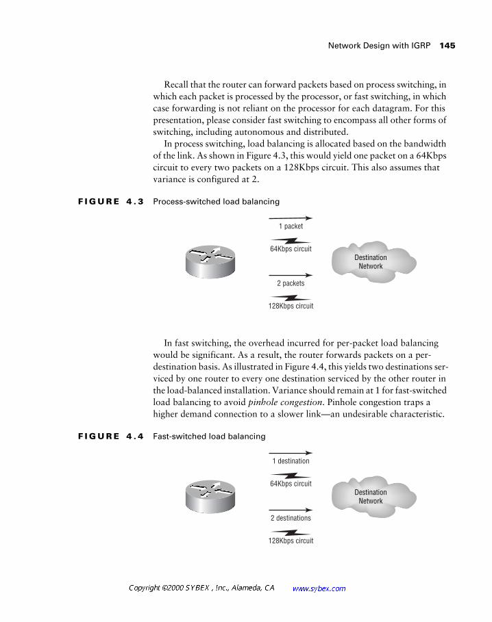
Network Design with IGRP 145
Recall that the router can forward packets based on process switching, in which each packet is processed by the processor, or fast switching, in which case forwarding is not reliant on the processor for each datagram. For this presentation, please consider fast switching to encompass all other forms of switching, including autonomous and distributed.
In process switching, load balancing is allocated based on the bandwidth of the link. As shown in Figure 4.3, this would yield one packet on a 64Kbps circuit to every two packets on a 128Kbps circuit. This also assumes that variance is configured at 2.
F I G U R E 4 . 3 Process-switched load balancing
In fast switching, the overhead incurred for per-packet load balancing would be significant. As a result, the router forwards packets on a per-destination basis. As illustrated in Figure 4.4, this yields two destinations ser-viced by one router to every one destination serviced by the other router in the load-balanced installation. Variance should remain at 1 for fast-switched load balancing to avoid pinhole congestion. Pinhole congestion traps a higher demand connection to a slower link—an undesirable characteristic.
F I G U R E 4 . 4 Fast-switched load balancing
1 packet
64Kbps circuit
2 packets
128Kbps circuit
DestinationNetwork
1 destination
64Kbps circuit
2 destinations
128Kbps circuit
DestinationNetwork
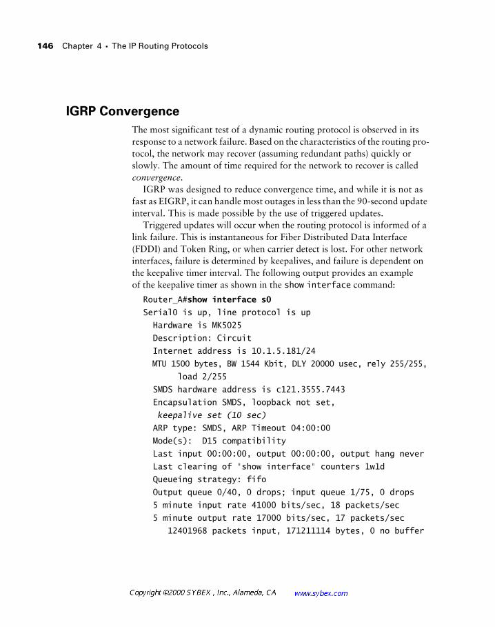
146 Chapter 4 � The IP Routing Protocols
IGRP Convergence
The most significant test of a dynamic routing protocol is observed in its response to a network failure. Based on the characteristics of the routing pro-tocol, the network may recover (assuming redundant paths) quickly or slowly. The amount of time required for the network to recover is called convergence.
IGRP was designed to reduce convergence time, and while it is not as fast as EIGRP, it can handle most outages in less than the 90-second update interval. This is made possible by the use of triggered updates.
Triggered updates will occur when the routing protocol is informed of a link failure. This is instantaneous for Fiber Distributed Data Interface (FDDI) and Token Ring, or when carrier detect is lost. For other network interfaces, failure is determined by keepalives, and failure is dependent on the keepalive timer interval. The following output provides an example of the keepalive timer as shown in the show interface command:
Router_A#show interface s0
Serial0 is up, line protocol is up
Hardware is MK5025
Description: Circuit
Internet address is 10.1.5.181/24
MTU 1500 bytes, BW 1544 Kbit, DLY 20000 usec, rely 255/255,
load 2/255
SMDS hardware address is c121.3555.7443
Encapsulation SMDS, loopback not set,
keepalive set (10 sec)
ARP type: SMDS, ARP Timeout 04:00:00
Mode(s): D15 compatibility
Last input 00:00:00, output 00:00:00, output hang never
Last clearing of "show interface" counters 1w1d
Queueing strategy: fifo
Output queue 0/40, 0 drops; input queue 1/75, 0 drops
5 minute input rate 41000 bits/sec, 18 packets/sec
5 minute output rate 17000 bits/sec, 17 packets/sec
12401968 packets input, 171211114 bytes, 0 no buffer
Network Design with IGRP 147
Received 0 broadcasts, 0 runts, 0 giants, 0 throttles
0 input errors, 0 CRC, 0 frame, 0 overrun, 0 ignored,
0 abort
10583498 packets output, 1920074976 bytes, 0 underruns
0 output errors, 0 collisions, 0 interface resets
0 output buffer failures, 0 output buffers swapped out
0 carrier transitions
Upon failure, IGRP will transmit a triggered update to notify its neighbors of the unreachable networks. The neighbors, or adjacent routers, will then trigger updates to their neighbors, ultimately leading to the information reaching all routers in the network. Each of these triggered updates occurs independently from the regular update, although the triggered update and the regular update may coincide. Holddown timers are also used to assist in the convergence process. By default, the holddown timer is equal to three times the update interval of IGRP, plus 10 seconds. This results in a default holddown time of 280 seconds, during which time the router will not respond to routes that have been poisoned, or advertised as unreachable. It is important to note that some designers eliminate the holddown timer on links with high bandwidth. Without the holddown function, it is possible to generate a significant amount of traffic during the convergence process. The command to manipulate this function is no metric holddown. Normally, if a higher metric route to a destination appears, it is poisoned to prevent loops.
Triggered updates are invoked on link-state changes only.
Designers should also note that the holddown timer does not dictate con-vergence times when load balancing is configured and that routes are flushed based on the flush timer. The flush timer is seven times the update interval, or 630 seconds, by default.
148 Chapter 4 � The IP Routing Protocols
Network Design with EIGRP
The Enhanced Interior Gateway Routing Protocol (EIGRP) is one of the more interesting protocols for the network designer to consider. First, the protocol is proprietary to Cisco, which will greatly limit the designer’s options in incorporating other vendors’ hardware. Second, the protocol offers many of the benefits found in OSPF without requiring a rigid design model. Unfortunately, it is this second item that frequently causes problems in EIGRP—designers and administrators use EIGRP without understanding it or planning for its use. This may be due to its position as a replacement for IGRP, which frequently adds the complexity of incorporating the legacy net-work into the design.
EIGRP is based on the distance-vector model, although it is quite advanced and shares components of link-state as well. The protocol supports variable-length subnet masks (VLSM), which can greatly assist the designer in IP address allocation. EIGRP works to prevent loops and speed conver-gence, both factors that assist the network architect. EIGRP also supports equal-cost load balancing, which can greatly augment the bandwidth and reliability of the network. Unequal-cost load balancing is also supported with the variance mechanism.
Network Design in the Real World: IGRP
In the financial and insurance industries, it seems as if every Cisco shop migrated to IGRP and has been cursed ever since. It is unfortunate that the protocol has garnered this reputation, as it is an improvement over IP RIP.
The majority of the problems associated with IGRP involve its lack of VLSM support. In addition, the proprietary nature of the protocol further limits its flexibility in the network.
Today, few networks are being designed around IGRP, and most companies have committed to migrations away from the protocol. There is little doubt that it will remain in use for some time, but EIGRP, OSPF, RIP v2, and other protocols will certainly replace it in the long run.
It is important to note that EIGRP configuration, discussed in the next sec-tion, is very similar to IGRP—an effort by Cisco to facilitate conversion.
Network Design with EIGRP 149
If there were a single negative factor with EIGRP, it would have to be its lack of documentation and use in the real world. This situation is quickly changing, but many companies have deployed IP EIGRP only to later remove it because of CPU, memory, and route-flapping issues. Once properly con-figured and designed, EIGRP quickly redeems itself, given its powerful fea-tures. One criterion towards this goal is to avoid using EIGRP in hub-and-spoke designs, as these configurations quickly demonstrate the protocol’s inability to scale and converge. This presentation of EIGRP will focus solely on IP EIGRP; it is important to note that EIGRP will support AppleTalk and IPX routing. However, separate tables are maintained for each of the three supported protocols, and each protocol uses separate hello messages, timers, and metrics.
In addition to the separate routing, topology, and neighbor tables main-tained on the router for each protocol, EIGRP uses reliable and unreliable transports to provide routing functions. The primary mechanism in EIGRP is the hello datagram, which is used to maintain verification that a router is still active. When a topology change event occurs in the network, the proto-col will establish a connection-oriented communications channel for the updates.
Many of the EIGRP commands and default behaviors are similar to IGRP in order to augment migration efforts. For example, EIGRP performs an auto-matic classful summarization like IGRP, although EIGRP adds VLSM support.
EIGRP Neighbors
One of the most limiting factors regarding EIGRP is the lack of detailed information about the protocol. A significant component of this is the neigh-bor relationship. Neighbor relationships are established between two routers running in the same EIGRP autonomous system (AS).
While the “Network Design in the Real World: EIGRP” sidebar provides additional tips regarding EIGRP, most designers would be well advised to consult with others who have deployed the protocol. Although EIGRP is extremely powerful, the reality is that little information is available regard-ing actual deployments. This can be a significant factor in deployments with high numbers of neighbors, poor addressing and design, and low memory and CPU availability on the routers. Many problems with EIGRP involve the number of neighbors, especially with the Route Switch Module (RSM) in the Catalyst product line. Unlike a router, the RSM typically terminates multiple
150 Chapter 4 � The IP Routing Protocols
networks and has many neighbors—more than are found in a typical instal-lation with routers. In addition, the RSM is relatively limited in terms of backplane connectivity (400Mbps) and processor (an RSP 2). Therefore, a high number of neighbors will affect an RSM before a comparable installa-tion with RSP 4s and a 7513 router—a factor that has impacted many EIGRP conversions.
The Diffusing Update Algorithm
The Diffusing Update Algorithm, or DUAL, is the route-determination pro-cess in EIGRP. It permits the routing process to determine whether a path advertised is looped or loop-free. In addition, routers using EIGRP can deter-mine alternative paths before receiving updates that link failure has occurred from other routers. The concept of always having a “second-best” route in memory greatly aids in reducing convergence time, which can increase the reliability of the network design.
The primary design criterion for EIGRP is the maintenance of a loop-free topology at all points in the route-calculation process. At the same time, EIGRP attempts to reduce the total amount of convergence time by main-taining alternate routes in memory, a factor that typically works against loop-free techniques. EIGRP maintains information about successors (the best possible route to a destination) and feasible successors (the second-best route to a destination) in order to reduce the amount of time involved in convergence.
Like OSPF, EIGRP uses a hello mechanism to monitor router availability. These messages are sent every five seconds and significantly differentiate EIGRP from other distance-vector protocols. Most distance-vector proto-cols rely on timers to detect route failure. The benefit of hello messages is the avoidance of black holes—routes that lead to nothing. It is also important to note that updates in EIGRP are sent only when necessary and only to those destinations that require them. This greatly reduces the overhead of the pro-tocol from a bandwidth perspective. In addition, these updates are sent reli-ably, which means that all updates are sequenced and acknowledged. This works to guarantee convergence assuming that all other factors, including router memory and processor, are working properly. The protocol used for EIGRP is the Reliable Transport Protocol (RTP), but, contrary to its name, it may transport unreliable messages as well.
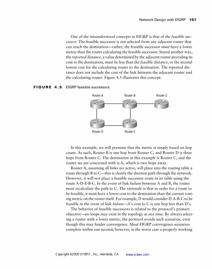
Network Design with EIGRP 151
One of the misunderstood concepts in EIGRP is that of the feasible suc-cessor. The feasible successor is not selected from any adjacent router that can reach the destination—rather, the feasible successor must have a lower metric than the router calculating the feasible successor. Stated another way, the reported distance, a value determined by the adjacent router providing its cost to the destination, must be less than the feasible distance, or the second-lowest cost for the calculating router to the destination. The reported dis-tance does not include the cost of the link between the adjacent router and the calculating router. Figure 4.5 illustrates this concept.
F I G U R E 4 . 5 EIGRP feasible successors
In this example, we will presume that the metric is simply based on hop count. As such, Router B is one hop from Router C, and Router D is three hops from Router C. The destination in this example is Router C, and the router we are concerned with is A, which is two hops away.
Router A, assuming all links are active, will place into the routing table a route through B to C—this is clearly the shortest path through the network. However, it will not place a feasible successor route in its table using the route A-D-E-B-C. In the event of link failure between A and B, the router must recalculate the path to C. The rationale is that in order for a route to be feasible, it must have a lower cost to the destination than the current rout-ing metric on the router itself. For example, D would consider D-A-B-C to be feasible in the event of link failure—A’s cost to C is one hop less than D’s.
The behavior of feasible successors is related to the protocol’s primary objective—no loops may exist in the topology at any time. By always select-ing a router with a lower metric, the protocol avoids such scenarios, even though this may hinder convergence. Most EIGRP convergence scenarios complete within one second; however, in the worst case a properly working
Router A Router B
Router D Router E
Router C
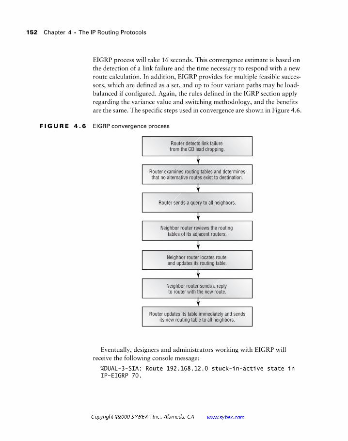
152 Chapter 4 � The IP Routing Protocols
EIGRP process will take 16 seconds. This convergence estimate is based on the detection of a link failure and the time necessary to respond with a new route calculation. In addition, EIGRP provides for multiple feasible succes-sors, which are defined as a set, and up to four variant paths may be load-balanced if configured. Again, the rules defined in the IGRP section apply regarding the variance value and switching methodology, and the benefits are the same. The specific steps used in convergence are shown in Figure 4.6.
F I G U R E 4 . 6 EIGRP convergence process
Eventually, designers and administrators working with EIGRP will receive the following console message:
%DUAL-3-SIA: Route 192.168.12.0 stuck-in-active state in IP-EIGRP 70.
Router detects link failure from the CD lead dropping.
Router examines routing tables and determinesthat no alternative routes exist to destination.
Router sends a query to all neighbors.
Neighbor router reviews the routing tables of its adjacent routers.
Neighbor router locates route and updates its routing table.
Neighbor router sends a reply to router with the new route.
Router updates its table immediately and sendsits new routing table to all neighbors.
Network Design with EIGRP 153
This message may result from one of two problems—the first is simply a lack of available memory on the router to calculate the route. A route that is unparsed (undergoing recomputation) is considered active, whereas a sta-ble route that has been placed in the tables is passive. The second possible cause is a lack of bandwidth on the link between the two routers—prevent-ing communications between them for route update transmission. One method for addressing this problem is to augment the available bandwidth EIGRP is allocated. By default, EIGRP cannot consume more than 50 per-cent of the link. Another technique that can help is route summarization.
Designers should keep in mind that EIGRP maintains not only its routing table but also the routing table of each adjacent router. This fact is signifi-cant in understanding the importance of summarization, small neighbor relationships, and the routing update mechanism. DUAL uses this additional information to determine the feasible successor, and this data determines whether a computation is required.
Administrators may wish to adjust the amount of bandwidth available to EIGRP with the ip bandwidth-percent eigrp command. This permits mod-ification of the default 50 percent utilization allowed, which may be neces-sary for slower links in order to speed convergence.
Route summarization in EIGRP is automatic across major network bound-aries, but many administrators disable this feature in order to take advantage of manual summarization on all boundaries and gain more control. For dis-contiguous subnets, this feature must be disabled. This powerful feature not only reduces the size of the routing table but also provides a strong motivator for readdressing projects. The best EIGRP designs yield very small core routing tables—divided at a very high level based on summarization.
A number of companies have migrated to the reserved addresses specified in RFC 1918 in order to reduce the public Internet addressing shortage under IP v4. Designers should give careful consideration to both IP v6 and the use of public IP addresses—a number of service providers are finding it difficult to provide Layer 3 solutions with private addresses.
Designers should also note that EIGRP can maintain six routes to a des-tination—a characteristic that can reduce convergence time, as the router simply moves packets to the remaining paths.
154 Chapter 4 � The IP Routing Protocols
Another feature of EIGRP that is often overlooked is mobile hosting. A mobile host is a host that is no longer on its natural subnet. The router will place an exception route to the host in the table—the more specific route superseding the subnet route. Clearly, this can reduce efficiency and greatly increase the size of the routing table. However, as wireless devices become more common in the enterprise, the demand for this feature will increase. This feature was added in IOS version 10.2.
Interrelationships with IGRP
EIGRP is built in part on the foundation laid by IGRP. Many designers migrate to EIGRP to add features to their networks while retaining some of the benefits of IGRP. Most conversions are promoted by the need for VLSM, although faster convergence and other benefits may also lead to the recom-mendation for conversion.
There are two methods for redistributing IGRP and EIGRP routes. The first is to assign the same autonomous system (AS) number to both the IGRP and EIGRP processes. The second method is similar to the technique used for other routing protocols—the administrator manually places a redistribution command into the routing process.
Of the two redistribution methods, most experienced designers lean toward the second, or manual redistribution. This solution affords a greater degree of control over the process, which frequently becomes desirable. For example, EIGRP, unlike IGRP, provides a method for identifying routes as internal or external. An external route is one that was learned from another routing process. IGRP contains no such mechanism, which may impact the administrative distance and other factors the router will use when selecting a route. Manual redistribution also affords the opportunity to use distribu-tion lists, route maps, and other techniques to control the routing process.
Designers should use some care when converting from IGRP to EIGRP. Perhaps the most significant design criterion is to select only a few routers to handle the redistribution—ideally, routers in the core or distribution layers.
EIGRP designs tend to be most successful when using the three-tier, hierar-chical model.
Network Design with EIGRP 155
This section has noted that designers typically select EIGRP as a replace-ment for IGRP without describing some of the reasons a designer would do so. Here is a list of advantages provided by EIGRP:
Low bandwidth consumption (stable network) When the network is stable, the protocol relies only on hello packets. This greatly reduces the amount of bandwidth needed for updates.
Efficient use of bandwidth during convergence When a change is made to the routing topology, EIGRP will enter a period of active convergence. During this time, the routers will attempt to rebuild their routing tables to account for the change—typically the failure of an interface. To conserve bandwidth, EIGRP will communicate only changes in the topological database to other routers in that AS, as opposed to communication of the entire routing table, which consumes a great deal of bandwidth, especially in larger networks.
Support for VLSM As noted previously, EIGRP supports variable-length subnet masks. This support, along with support for classless Inter-net domain routing (CIDR), can greatly assist the network designer by offering greater flexibility in IP addressing.
Designers should use some caution in deploying VLSM in the network. Ideally, there should be only two or three masks for the entire enterprise. These typically include /30 and /24. The reason for this is not specifically a routing protocol limitation, but rather a consideration for troubleshooting and other support issues. The concepts of VLSM and CIDR have been around for many years, but an understanding of both features, especially in the server and workstation arenas, is still wanting—network designers may find that their workstation support staffs are unfamiliar with these concepts and may find resistance to a readdressing effort. Remember that IP address-ing affects not only the network, but also all other devices in the network, including Dynamic Host Configuration Protocol (DHCP), workstations, and servers. In well-administered networks, the use of VLSM is transparent to end users. However, the lack of familiarity by administrators and users can cause problems—consider the impact on the network if end users changed their subnet mask to the default value because they found it to be wrong. The problem is not technical but educational. Fortunately, these con-cerns and issues are being quickly eliminated from the landscape as VLSM gains in popularity and designers become more familiar with it. Recall from
156 Chapter 4 � The IP Routing Protocols
Chapter 3 that VLSM helps designers construct efficient IP addressing schemes.
EIGRP and IGRP share the same composite routing metrics and mathe-matical weights; however, EIGRP supports metrics up to 32 bits. This differs from IGRP, which supports only 24 bits for the metric. EIGRP will automat-ically handle this issue, and after conversion metrics from either protocol are interchangeable.
Pay special attention to memory and CPU capacity on routers that will run EIGRP. The protocol can be very memory intensive, especially as the number of neighbors increases.
Network Design in the Real World: EIGRP
On the surface, it would appear that most Cisco-only networks should auto-matically use EIGRP. The protocol provides extremely fast convergence, relatively easy configuration, and variable-length subnetting.
Unfortunately, as with most things, it is not that simple to deploy EIGRP. The most significant problem frequently relates to memory and CPU; how-ever, other factors can hinder deployment.
The simplest recommendations for designers thinking of deploying EIGRP fall into four basic areas, as follows:
� Maximize the amount of memory available on each router and increase the capacity of each router as the number of neighbors increases. There are formulas that predict the amount of memory that an EIGRP installa-tion will require based on the number of neighbors and the number of routes, but these solutions are far from accurate. One installation I con-sulted on, after the deployment failed, had over 40MB of free router memory—the formula predicted that just over 1MB was sufficient. The deployment was ultimately removed, but it is important to note that the most critical issue involved the number of neighbors.
Network Design with EIGRP 157
External EIGRP Routes
One of the most unique features in EIGRP is the concept of an external route, which is how IGRP routes are tagged in EIGRP upon redistribution. Exter-nal routes are learned from one of the following:
� A static route injected into the protocol
� A route learned from redistribution from another EIGRP AS
� Routes learned from other protocols, including IGRP
All routes tagged as external are given a higher administrative distance than internal EIGRP routes. This effectively weights the internal routes for preference, which typically benefits the overall network. However, designers
� Limit the number of neighbors. This is easier said than done, especially when the network has evolved over time. One technique is to use pas-sive interfaces, although doing so significantly diminishes the overall benefits of EIGRP. Cisco recommends the use of ODR in hub-and-spoke designs, which can also reduce the number of neighbor relationships, but again, this reduces the overall benefits of EIGRP. The generic guide-lines recommend that EIGRP neighbors be kept to fewer than 30; how-ever, this is dependent on the amount of memory and the number of routes. Networks have failed with fewer neighbors, and a small number of networks have deployed over 70 neighbors successfully.
� Don’t use the automatic redistribution feature unless the network is very simple. Automatic redistribution is a feature Cisco provides in order to make IGRP-to-EIGRP migration easier. You configure this feature by set-ting the AS number to the same value in the two protocols. The auto-matic feature works well, but many administrators find that it does not afford enough control over the redistribution process, which may be necessary for the migration.
� Administrators and designs should disable automatic route summariza-tion and manually summarize routes whenever possible. Route summa-rization is an automatic process within the major network address, and it may require readdressing. However, summarization reduces the size of the routing table and can further enhance stability and convergence.
158 Chapter 4 � The IP Routing Protocols
will wish to monitor this characteristic to ascertain the appropriateness of the routing table and to avoid asymmetric routing, if desired. Asymmetric routing is a situation wherein the outbound packets traverse a different path than the inbound packets. Such a design can make troubleshooting more difficult.
When EIGRP tags a route as external, it includes additional information about the route in the topology table. This information includes the following:
� The router ID of the router that redistributed the route (EIGRP redis-tribution) and the AS number of that router
� The protocol used in the external network
� The metric or cost received with the route
� An external route tag that the administrator can use for filtering
IGRP does not provide an external route mechanism. Therefore, the protocol cannot differentiate between internally and externally learned routes.
Network Design with OSPF
The Open Shortest Path First (OSPF) protocol is perhaps one of the most difficult routing protocols to configure correctly. This is due to the pro-tocol’s feature set, which includes route summarization and the ability to use areas to logically divide various elements in the network. OSPF is a nonpro-prietary, link-state routing protocol for IP. It was developed to resolve some of the problems found with the RIP, including slow convergence, suscepti-bility to routing loops, and limited scalability. Given its nonproprietary nature, OSPF may be better suited for network designs than IGRP and EIGRP when non-Cisco equipment is a design criterion. Many educational networks use OSPF.
OSPF supports various network types, including point-to-point and broadcast/nonbroadcast multiaccess networks. Hellos are used to establish neighbor relationships under most circumstances; however, manual config-uration is needed for nonbroadcast multiaccess networks. The hello mecha-
Network Design with OSPF 159
nism communicates with the designated router in each area and will be presented in greater detail later in this chapter. These occur at 10-second intervals and do not incorporate the entire routing table. Every 30 minutes, OSPF will send a summary link-state database, regardless of link failure; the rest of the time only hellos will traverse the link. Link failure will cause addi-tional updates, and this process will be defined later as well.
OSPF uses the Dijkstra algorithm to calculate the shortest path for the network. In addition, OSPF supports VLSM and discontiguous subnets. Dis-contiguous subnets are subnets within a major network that are split by a different major network.
Apart from a VLSM-aware routing protocol, such as OSPF, discontiguous sub-nets are handled by the use of secondaries, or tunnels to link the two seg-ments of the major network.
From a design perspective, OSPF relates well with the textbook three-tier model. Consider the following guidelines and limitations of the protocol as they relate to the three-tier model:
Keep workstations and other devices off the backbone. In both mod-els, the core/backbone is a critical resource that should never contain non-network devices. In designing a small network, the designer may use OSPF with a single area—the special backbone area zero. Under these cir-cumstances, workstations and other devices will have to be included in this area. Under all other circumstances, designers will wish to keep the core as a secure transit area. This will reduce eavesdropping efforts and maintain a stable network. Note that OSPF backbones are best served when hosts are not placed in this backbone, a design criterion shared with the hierarchical model.
Maintain a simple backbone topology. As with the previous guideline, both OSPF and the three-tier model benefit from stable, simple backbones.
Limit each area to less than 100 routers and incorporate no more than 28 areas in the network. These Cisco recommendations for OSPF design match well with the demands of most networks designed under the three-tier model.
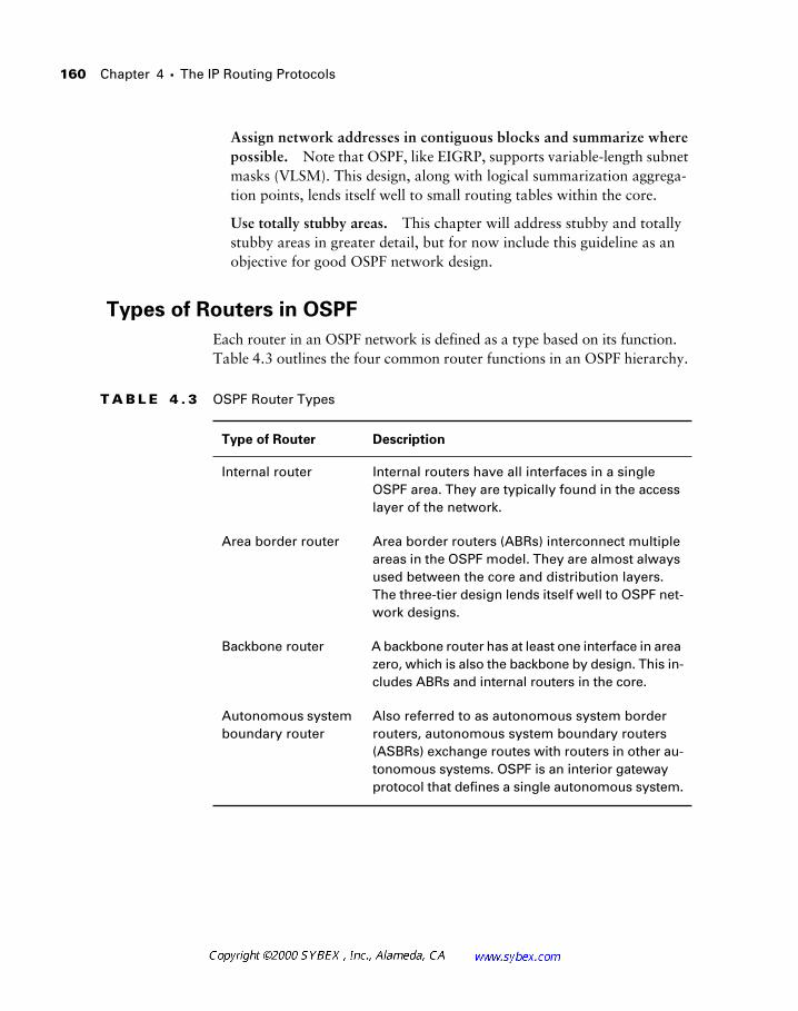
160 Chapter 4 � The IP Routing Protocols
Assign network addresses in contiguous blocks and summarize where possible. Note that OSPF, like EIGRP, supports variable-length subnet masks (VLSM). This design, along with logical summarization aggrega-tion points, lends itself well to small routing tables within the core.
Use totally stubby areas. This chapter will address stubby and totally stubby areas in greater detail, but for now include this guideline as an objective for good OSPF network design.
Types of Routers in OSPF
Each router in an OSPF network is defined as a type based on its function. Table 4.3 outlines the four common router functions in an OSPF hierarchy.
T A B L E 4 . 3 OSPF Router Types
Type of Router Description
Internal router Internal routers have all interfaces in a single OSPF area. They are typically found in the access layer of the network.
Area border router Area border routers (ABRs) interconnect multiple areas in the OSPF model. They are almost always used between the core and distribution layers. The three-tier design lends itself well to OSPF net-work designs.
Backbone router A backbone router has at least one interface in area zero, which is also the backbone by design. This in-cludes ABRs and internal routers in the core.
Autonomous system boundary router
Also referred to as autonomous system border routers, autonomous system boundary routers (ASBRs) exchange routes with routers in other au-tonomous systems. OSPF is an interior gateway protocol that defines a single autonomous system.
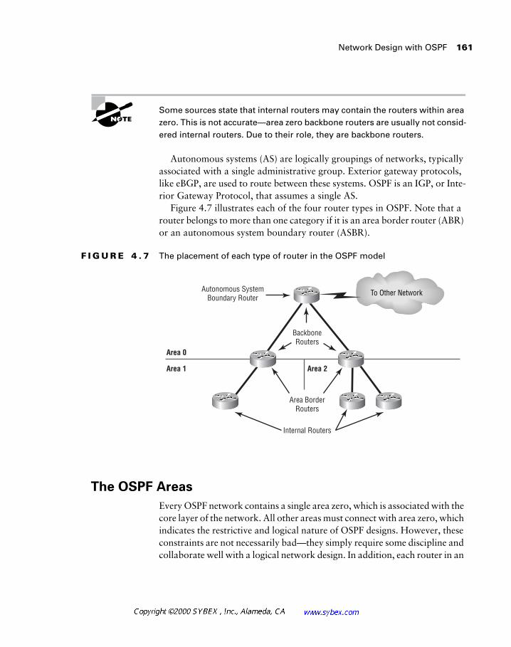
Network Design with OSPF 161
Some sources state that internal routers may contain the routers within area zero. This is not accurate—area zero backbone routers are usually not consid-ered internal routers. Due to their role, they are backbone routers.
Autonomous systems (AS) are logically groupings of networks, typically associated with a single administrative group. Exterior gateway protocols, like eBGP, are used to route between these systems. OSPF is an IGP, or Inte-rior Gateway Protocol, that assumes a single AS.
Figure 4.7 illustrates each of the four router types in OSPF. Note that a router belongs to more than one category if it is an area border router (ABR) or an autonomous system boundary router (ASBR).
F I G U R E 4 . 7 The placement of each type of router in the OSPF model
The OSPF Areas
Every OSPF network contains a single area zero, which is associated with the core layer of the network. All other areas must connect with area zero, which indicates the restrictive and logical nature of OSPF designs. However, these constraints are not necessarily bad—they simply require some discipline and collaborate well with a logical network design. In addition, each router in an
To Other Network
Area 1 Area 2
Area 0
BackboneRouters
Area BorderRouters
Internal Routers
Autonomous SystemBoundary Router
162 Chapter 4 � The IP Routing Protocols
area will have the same link-state database, which will incorporate informa-tion from all link-state advertisements (LSAs) for the area. Within the area, this information will incorporate specific links, and when learned from other areas and external (other AS) sources, this information will include specific links, summary links, and default links.
The concept of areas benefits the network greatly. For instance, conver-gence times can be greatly reduced by summarizing routes at the area border router. In addition, the requirement that all areas connect directly with area zero works to limit the depth of the entire network, which typically aids in the design and troubleshooting processes.
While it is preferable to keep all areas directly connected to area zero, it is pos-sible to attach an area to area zero through another OSPF area. This is called a virtual link. Designers should avoid using virtual links whenever possible.
Route summarization is a manual process within OSPF, and it requires a bit of planning. For established networks, it may require a complete readdressing of the network. Summarization works best when a large allo-cation of contiguous subnets is availed to each area. The summary link advertisement represents the block to the adjacent areas. It is important to note that large allocations may lead to wasted addresses. Therefore, many designers opt to use the Internet-reserved private address space, RFC 1918, when readdressing for OSPF deployments. The technique used to divide the address space is called bit splitting. This is effectively the same process used in subnetting and supernetting—a number of bits are used to define the significant bits, the bits used in defining the summarization.
It can be preferable to make each summarization area equal; however, sub-nets within the area can take advantage of VLSM functionality. Remember that VLSM address allocations are best limited to two or three masks.
The biggest advantage to summarization is the impact it has on both the routing table and convergence. Summarized routes may take the place of hundreds of specific routes. In addition, summarization can shield routers from flapping link overhead in a different area. This greatly increases the sta-bility of the network—areas outside of the flapping route do not recalculate
Network Design with OSPF 163
via the shortest path first (SPF) algorithm, nor do the routing tables change inside the shielded area.
Within each area, a single router is elected to be the designated router. The designated router, or DR, is selected by an election process that uses the highest IP address on the router. Most administrators use the loopback inter-face to override the highest IP address and manually manage the election of the DR. A Priority-ID may also be used to determine DR during election. It is preferable to use a router with the most memory and CPU capacity for the DR. In addition to the DR, a backup designated router (BDR) is also selected to provide redundancy in the event the primary router fails. The designated router provides an aggregation point for OSPF LSAs. Note that the com-mand ip ospf priority may be used to make a router the DR. Under these circumstances, the IP address is used in the event of a tie.
One last consideration for designers is the configuration of stubby areas and totally stubby areas. (Don’t laugh, that’s what they’re called.)
A stubby area consolidates external links and forwards summary LSAs, specific LSAs, and the default external link, which is analogous to the default route of 0.0.0.0.
The concept of a totally stubby area is Cisco IOS-specific. Only the default link is forwarded into the area by the area border router. The com-mand to configure this feature is area {N} stub no-summary. Because the totally stubby area receives only a default route, it is limited; however, it also works to control the total number of routes advertised into an area, which may benefit the designer in controlling routing propagation.
OSPF Link-State Advertisements
As a link-state protocol, OSPF relies on advertisements to announce infor-mation regarding the network. The link-state advertisements are given a sequence number and acknowledged, resulting in reliable information trans-fer. This feature aids in the fast convergence offered by the protocol. There are five primary types of OSPF link-state advertisements, as identified in Table 4.4.
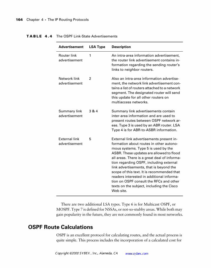
164 Chapter 4 � The IP Routing Protocols
There are two additional LSA types. Type 6 is for Multicast OSPF, or MOSPF. Type 7 is defined for NSSAs, or not-so-stubby areas. While both may gain popularity in the future, they are not commonly found in most networks.
OSPF Route Calculations
OSPF is an excellent protocol for calculating routes, and the actual process is quite simple. This process includes the incorporation of a calculated cost for
T A B L E 4 . 4 The OSPF Link-State Advertisements
Advertisement LSA Type Description
Router link advertisement
1 An intra-area information advertisement, the router link advertisement contains in-formation regarding the sending router’s links to neighbor routers.
Network link advertisement
2 Also an intra-area information advertise-ment, the network link advertisement con-tains a list of routers attached to a network segment. The designated router will send this update for all other routers on multiaccess networks.
Summary link advertisement
3 & 4 Summary link advertisements contain inter-area information and are used to present routes between OSPF network ar-eas. Type 3 is used by an ABR router. LSA Type 4 is for ABR-to-ASBR information.
External link advertisement
5 External link advertisements present in-formation about routes in other autono-mous systems. Type 5 is used by the ASBR. These updates are allowed to flood all areas. There is a great deal of informa-tion regarding OSPF, including external link advertisements, that is beyond the scope of this text. It is recommended that readers interested in additional informa-tion on OSPF consult the RFCs and other texts on the subject, including the Cisco Web site.
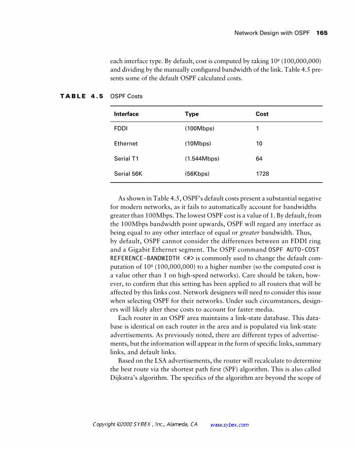
Network Design with OSPF 165
each interface type. By default, cost is computed by taking 108 (100,000,000) and dividing by the manually configured bandwidth of the link. Table 4.5 pre-sents some of the default OSPF calculated costs.
As shown in Table 4.5, OSPF’s default costs present a substantial negative for modern networks, as it fails to automatically account for bandwidths greater than 100Mbps. The lowest OSPF cost is a value of 1. By default, from the 100Mbps bandwidth point upwards, OSPF will regard any interface as being equal to any other interface of equal or greater bandwidth. Thus, by default, OSPF cannot consider the differences between an FDDI ring and a Gigabit Ethernet segment. The OSPF command OSPF AUTO-COST REFERENCE-BANDWIDTH <#> is commonly used to change the default com-putation of 108 (100,000,000) to a higher number (so the computed cost is a value other than 1 on high-speed networks). Care should be taken, how-ever, to confirm that this setting has been applied to all routers that will be affected by this links cost. Network designers will need to consider this issue when selecting OSPF for their networks. Under such circumstances, design-ers will likely alter these costs to account for faster media.
Each router in an OSPF area maintains a link-state database. This data-base is identical on each router in the area and is populated via link-state advertisements. As previously noted, there are different types of advertise-ments, but the information will appear in the form of specific links, summary links, and default links.
Based on the LSA advertisements, the router will recalculate to determine the best route via the shortest path first (SPF) algorithm. This is also called Dijkstra’s algorithm. The specifics of the algorithm are beyond the scope of
T A B L E 4 . 5 OSPF Costs
Interface Type Cost
FDDI (100Mbps) 1
Ethernet (10Mbps) 10
Serial T1 (1.544Mbps) 64
Serial 56K (56Kbps) 1728
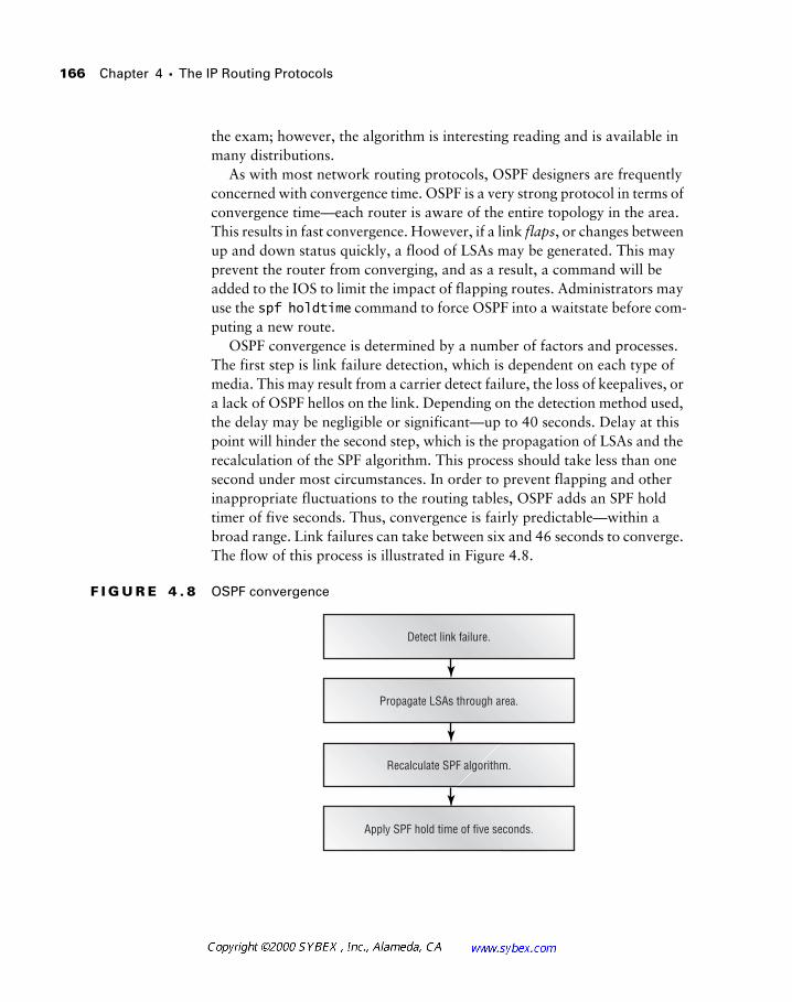
166 Chapter 4 � The IP Routing Protocols
the exam; however, the algorithm is interesting reading and is available in many distributions.
As with most network routing protocols, OSPF designers are frequently concerned with convergence time. OSPF is a very strong protocol in terms of convergence time—each router is aware of the entire topology in the area. This results in fast convergence. However, if a link flaps, or changes between up and down status quickly, a flood of LSAs may be generated. This may prevent the router from converging, and as a result, a command will be added to the IOS to limit the impact of flapping routes. Administrators may use the spf holdtime command to force OSPF into a waitstate before com-puting a new route.
OSPF convergence is determined by a number of factors and processes. The first step is link failure detection, which is dependent on each type of media. This may result from a carrier detect failure, the loss of keepalives, or a lack of OSPF hellos on the link. Depending on the detection method used, the delay may be negligible or significant—up to 40 seconds. Delay at this point will hinder the second step, which is the propagation of LSAs and the recalculation of the SPF algorithm. This process should take less than one second under most circumstances. In order to prevent flapping and other inappropriate fluctuations to the routing tables, OSPF adds an SPF hold timer of five seconds. Thus, convergence is fairly predictable—within a broad range. Link failures can take between six and 46 seconds to converge. The flow of this process is illustrated in Figure 4.8.
F I G U R E 4 . 8 OSPF convergence
Detect link failure.
Propagate LSAs through area.
Recalculate SPF algorithm.
Apply SPF hold time of five seconds.
Network Design with OSPF 167
Convergence time factors may be negated somewhat by load balancing. OSPF supports up to four equal-cost paths per destination, which can main-tain connectivity in the event of a single link failure. As with other routing protocols, designers should use the bandwidth command to accurately reflect the capacity of their links and optimize traffic flows.
Network Design in the Real World: OSPF
OSPF configuration, done properly, can be more difficult than other proto-cols, as noted in the main text. However, many of the design concepts man-dated by OSPF are well suited for other routing protocols. This is especially true for route summarization.
There are two common issues with OSPF implementations. The first is the over-simplified model. The placement of all routers in area zero is affection-ately called the over-simplified model. A surprising number of fairly large networks have deployed this model in the past, and many designers unfa-miliar with OSPF may be tempted to do the same. The problem with this deployment is that it does not scale, and ultimately many of the benefits integrated into OSPF will be lost. It is better to complicate a small network design slightly by anticipating its growth than to take this shortcut.
The second common problem in OSPF design is redundancy and, more importantly, diversity. One large ATM network we were deploying was orig-inally slated for OSPF; however, backup links frequently crossed local access and transport area (LATA) boundaries. Crossing a LATA typically increases the cost for a circuit—in our design this almost tripled the recur-rent costs. As a result, to provide the needed redundancy, we had to con-sider virtual links or abandon the structure of OSPF in favor of a less-demanding protocol.
Clearly this was an unacceptable solution, and so our original design with symmetric distribution layers in different geographic locations was too dif-ficult to implement with the area constraints mandated by OSPF. There were alternatives, including the use of virtual links; however, each was deemed suboptimal. The network was ultimately deployed with EIGRP, which still permitted summarization at the access layer, and many of the other features required by the project, including fast-convergence and VLSM support.
168 Chapter 4 � The IP Routing Protocols
Network Design with ODR
On-demand routing, or ODR, is perhaps one of the most interesting routing protocols available on the Cisco platform—perhaps because it is not a routing protocol at all.
At present, ODR is not incorporated into the CID exam or its objectives. How-ever, the protocol is very useful in simplifying small hub-and-spoke network routing, as it adds virtually no overhead.
It would be most accurate to describe ODR as a routing process. How-ever, the process relies on the Cisco Discovery Protocol (CDP). The CDP packets are a proprietary method for exchanging information between two Cisco devices. The majority of this information is used in troubleshooting and administration. For example, CiscoWorks and other SNMP/RMON (remote monitoring) tools now use the CDP information to assist in the dis-covery and map-building processes.
ODR adds another function to CDP. By listening to CDP packets in a sim-ple hub-and-spoke design, a master router (located at the hub) is able to learn about all the other routers in the network. The remote routers are con-figured with a single default route to the hub. This design does not provide many of the benefits of a formal routing protocol, but it will provide con-nectivity and status regarding the remote router interfaces without consuming additional bandwidth. Of course, CDP can be disabled—it is on by default. Figure 4.9 illustrates a typical ODR installation.
As of this writing, Cisco does not support CDP on ATM links. However, this feature and support for secondary interfaces are documented as available in IOS 12.0.
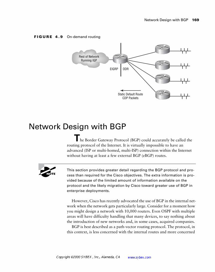
Network Design with BGP 169
F I G U R E 4 . 9 On-demand routing
Network Design with BGP
The Border Gateway Protocol (BGP) could accurately be called the routing protocol of the Internet. It is virtually impossible to have an advanced (ISP or multi-homed, multi-ISP) connection within the Internet without having at least a few external BGP (eBGP) routes.
This section provides greater detail regarding the BGP protocol and pro-cess than required for the Cisco objectives. The extra information is pro-vided because of the limited amount of information available on the protocol and the likely migration by Cisco toward greater use of BGP in enterprise deployments.
However, Cisco has recently advocated the use of BGP in the internal net-work when the network gets particularly large. Consider for a moment how you might design a network with 10,000 routers. Even OSPF with multiple areas will have difficulty handling that many devices, to say nothing about the introduction of new networks and, in some cases, acquired companies.
BGP is best described as a path-vector routing protocol. The protocol, in this context, is less concerned with the internal routes and more concerned
EIGRP ODR
Rest of NetworkRunning IGP
Static Default RouteCDP Packets
170 Chapter 4 � The IP Routing Protocols
with the relationships between autonomous systems. For this presentation, consider an AS to be synonymous with individual companies, although in actuality the term defines the administrative domain. BGP is also called an inter-autonomous system routing protocol.
Overall, BGP is a very powerful protocol—primarily due to two specific characteristics. First, the protocol removes the concept of network class and supports address summarization and supernetting like OSPF does. Second, BGP operates over TCP, which provides it with a more robust transport architecture than other routing protocols. Part of this function includes a graceful shutdown—errors and other messages are sent before the protocol shuts down whenever possible. BGP uses TCP port 179.
Another useful function in eBGP is the characteristic that governs its advertised routes. BGP will advertise to its peers only the routes that the BGP speaker uses, rather than routes only known from other announcements. Routes are further defined on a hop-by-hop basis.
There are three autonomous system types that designers considering BGP should understand:
Stub AS Provides a single exit point and is used for local traffic only. Local traffic is traffic that belongs to the AS.
Multi-homed AS A multi-homed AS provides multiple exit points for local traffic.
Transit AS A transit AS is used for both local and transit traffic. Transit traffic is traffic that is not destined for the autonomous system but uses that AS to reach another system. This type is typically used only in ISP environments.
BGP works by maintaining a direct transport layer connection between two systems and providing updates whenever changes occur. A full routing table is sent upon session establishment. Keepalive messages are sent period-ically to validate the integrity of the connection. These are sent, by default, at one-third the hold-time interval.
As of this writing, there are over 65,000 networks in the Internet routing table. This information is shown in the ip bgp summary that follows:
Inet_Rtr#show ip bgp summary
BGP table version is 17453706, main routing table version
17453706
65353 network entries and 101590 paths using 9735069 bytes
of memory
Network Design with BGP 171
14801 BGP path attribute entries using 1187400 bytes of
memory
3143 BGP filter-list cache entries using 50288 bytes of
memory
Dampening enabled. 57 history paths, 93 dampened paths
BGP activity 690913/625560 prefixes, 4454740/4353150 paths
4327988 prefixes revised.
Administrators are advised to use the loopback address on the router for all BGP traffic. Doing so can work to stabilize the routing process and maintain connectivity in the event of an interface failure. This stability is the result of the TCP session being established via the loopback interface—a link failure, given other paths, will not require re-establishment of the TCP session between BGP pairs.
Multi-homed BGP configurations can bias the exit point advertised by the eBGP peer. This is called the multi-exit discriminator, and it may be used to provide a fixed value—the lowest is preferred—or it may be based on the IGP metric, which is typically provided by OSPF. Note that this value does not propagate beyond the link.
Administrators may also use route maps to modify and influence the rout-ing tables. Route maps operate on a match-and-set model where conditions may be checked before the router applies the set. For example, the adminis-trator may wish to modify only routes from network 172.16.0.0. In this con-figuration, the route map would match 172.16.0.0 and then set the modified value. The administrator may wish to use this function to adjust the metric.
The following BGP configuration is provided as a sample of some of the commands used. In reality, BGP configurations can be very simple; however, most installations to the Internet require additional parameters that can cause difficulty. Notice how the specific IP address of each neighbor is pro-vided in the configuration and that the update-source for AS 65342 is defined as Loopback0. The route-map Filter has also been applied.
router bgp 65470
no synchronization
bgp dampening
network 10.9.14.0 mask 255.255.255.0
neighbor 192.168.19.33 remote-as 65391
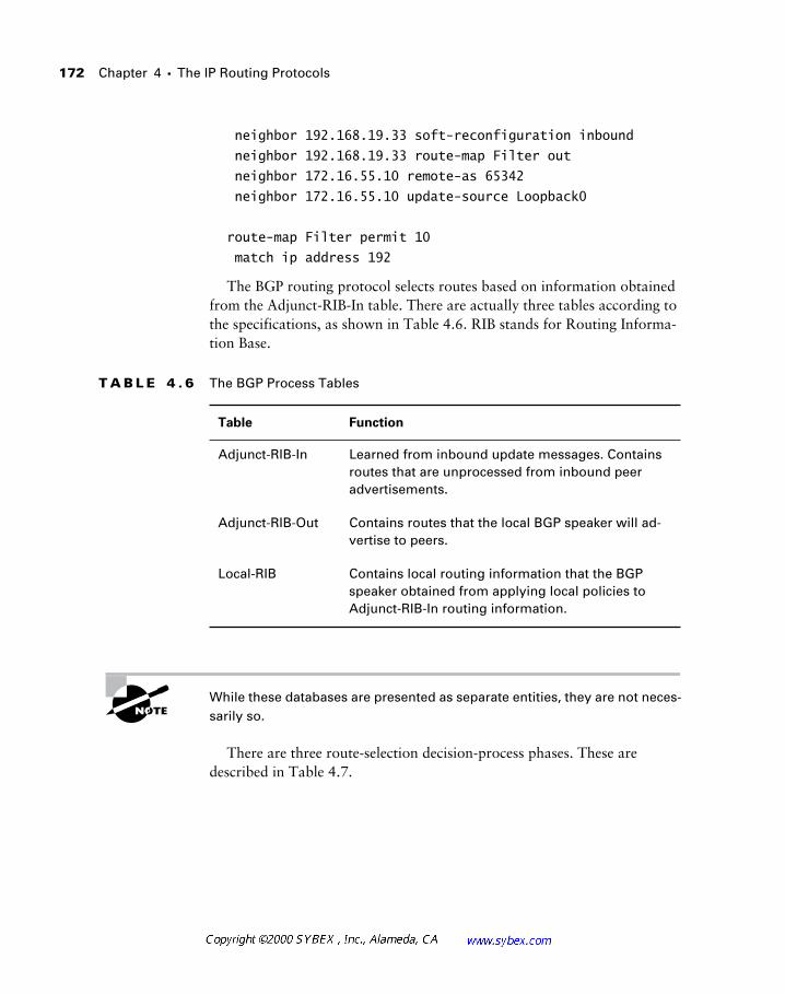
172 Chapter 4 � The IP Routing Protocols
neighbor 192.168.19.33 soft-reconfiguration inbound
neighbor 192.168.19.33 route-map Filter out
neighbor 172.16.55.10 remote-as 65342
neighbor 172.16.55.10 update-source Loopback0
route-map Filter permit 10
match ip address 192
The BGP routing protocol selects routes based on information obtained from the Adjunct-RIB-In table. There are actually three tables according to the specifications, as shown in Table 4.6. RIB stands for Routing Informa-tion Base.
While these databases are presented as separate entities, they are not neces-sarily so.
There are three route-selection decision-process phases. These are described in Table 4.7.
T A B L E 4 . 6 The BGP Process Tables
Table Function
Adjunct-RIB-In Learned from inbound update messages. Contains routes that are unprocessed from inbound peer advertisements.
Adjunct-RIB-Out Contains routes that the local BGP speaker will ad-vertise to peers.
Local-RIB Contains local routing information that the BGP speaker obtained from applying local policies to Adjunct-RIB-In routing information.
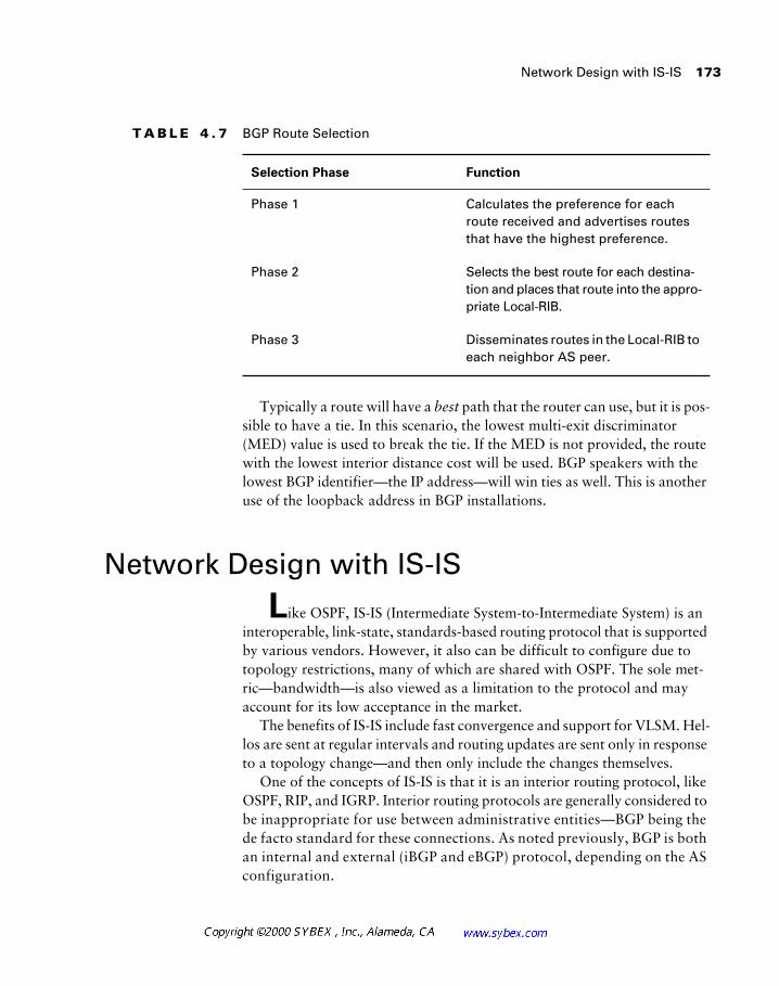
Network Design with IS-IS 173
Typically a route will have a best path that the router can use, but it is pos-sible to have a tie. In this scenario, the lowest multi-exit discriminator (MED) value is used to break the tie. If the MED is not provided, the route with the lowest interior distance cost will be used. BGP speakers with the lowest BGP identifier—the IP address—will win ties as well. This is another use of the loopback address in BGP installations.
Network Design with IS-IS
Like OSPF, IS-IS (Intermediate System-to-Intermediate System) is an interoperable, link-state, standards-based routing protocol that is supported by various vendors. However, it also can be difficult to configure due to topology restrictions, many of which are shared with OSPF. The sole met-ric—bandwidth—is also viewed as a limitation to the protocol and may account for its low acceptance in the market.
The benefits of IS-IS include fast convergence and support for VLSM. Hel-los are sent at regular intervals and routing updates are sent only in response to a topology change—and then only include the changes themselves.
One of the concepts of IS-IS is that it is an interior routing protocol, like OSPF, RIP, and IGRP. Interior routing protocols are generally considered to be inappropriate for use between administrative entities—BGP being the de facto standard for these connections. As noted previously, BGP is both an internal and external (iBGP and eBGP) protocol, depending on the AS configuration.
T A B L E 4 . 7 BGP Route Selection
Selection Phase Function
Phase 1 Calculates the preference for each route received and advertises routes that have the highest preference.
Phase 2 Selects the best route for each destina-tion and places that route into the appro-priate Local-RIB.
Phase 3 Disseminates routes in the Local-RIB to each neighbor AS peer.
174 Chapter 4 � The IP Routing Protocols
The exterior routing protocol, ES-IS, is used for exterior routing.
IS-IS makes use of a two-area structure, with area defined as layers. Layer 1 is used for intra-domain routing, whereas Layer 2 is used for inter-domain routing—Layer 2 linking two routing domains (areas) in the IS-IS syntax. Hierarchies are established as Layer 1 routers need only find a Layer 2 router for forwarding—similar to a border router in OSPF.
Metrics in IS-IS, by default, are comprised of a single path value—the maximum value of which is 1024. Individual links are limited to a maximum setting of 64. IS-IS also provides a limited quality-of-service function in its CLNP header, which can account for other link costs. CLNP stands for Con-nectionless Network Protocol, which was originally developed for the rout-ing of DECnet/OSI packets. The protocol has been modified to support IP. At the present time, there is little reason to select IS-IS—EIGRP and OSPF dominate the marketplace. The Cisco Web site provides additional informa-tion on the protocol, should you wish to study it further.
Summary
This chapter addressed the IP routing protocols and processes as they relate to network design. These protocols include the following:
� Static (actually not a protocol, but a process)
� RIP
� RIP v2
� OSPF
� IGRP
� EIGRP
� ODR (actually not a protocol, but a process)
� BGP
Summary 175
The chapter also identified some of the reasons IP routing might be better handled by one protocol than another. Incorporated into that decision were a number of criteria, including the following:
� Availability
� Scalability
� Ease of administration
� Bandwidth efficiency
� Router memory utilization
� Router CPU utilization
� Multi-vendor interoperability
� Adjacencies (number of neighbors)
� Support staff familiarity
In addition, the chapter addressed the proprietary IGRP routing protocol and presented features and options that the designer might wish to consider when deploying this routing protocol. Some of these issues included conver-gence and efficiency.
The presentation on OSPF discussed several of the advantages offered by this protocol, including its wide availability. In addition, designers should feel comfortable with a number of the implementation techniques used for successful OSPF designs, including the following:
� Route summarization, including address-allocation efficiencies
� Simple backbone designs with no hosts
� Fewer than 100 routers per area and fewer than 28 areas
The process by which convergence occurs was also described.

176 Chapter 4 � The IP Routing Protocols
Review Questions
1. IS-IS defines areas:
A. As Layer 1, which is intra-area, and Layer 2, which links two areas
B. As a single AS linked by multiple ABSRs
C. As multiple Layer 1 inter-area links
D. As Layer 2 intra-areas and Layer 1 transit areas.
2. Under IGRP, split horizon would be off, by default, for which of the following?
A. Token Ring
B. Ethernet
C. SMDS
D. FastEthernet
E. None of the above
3. IGRP will do which of the following?
A. Send hellos every 10 seconds.
B. Send hellos every two hours.
C. Send the entire routing table every 90 seconds.
D. Send only changes to the routing table every 90 seconds.
4. In IGRP, the default update timer is:
A. 30 seconds
B. 60 seconds
C. 90 seconds
D. 120 seconds
Review Questions 177
5. In IGRP, the default holddown timer is:
A. 30 seconds
B. 90 seconds
C. 270 seconds
D. 280 seconds
E. 300 seconds
6. By default, IGRP will use only which of the following to determine a route’s metric?
A. Bandwidth
B. Delay
C. Reliability
D. Loading
E. MTU
F. Hops
7. Which of the following would be a benefit in using static routes?
A. Low bandwidth utilization
B. 10-second updates
C. Automatic configuration
D. Load balancing
8. Which of the following routing protocols support VLSM?
A. RIP
B. RIP v2
C. OSPF
D. IGRP
E. EIGRP
178 Chapter 4 � The IP Routing Protocols
9. Which of the following is a benefit of VLSM?
A. Faster convergence with RIP
B. Faster convergence with OSPF
C. Faster convergence with IGRP
D. Efficient IP address assignment
10. Which of the following protocols uses a persistent TCP connection to communicate with neighbor routers?
A. OSPF
B. BGP
C. RIP
D. EIGRP
11. A virtual link is which of the following?
A. A conduit through area zero
B. A conduit through two EIGRP autonomous systems
C. A connection between an EIGRP AS and an OSPF area
D. A connection between a remote area and area zero via another area
12. True or false: IGRP uses triggered updates.
A. True
B. False
13. EIGRP can maintain how many routes per destination?
A. 1
B. 2
C. 4
D. 6
Review Questions 179
14. A discontiguous subnet is:
A. Two or more subnets from a major network divided by a different major network
B. A single summary route from a major network
C. Not permitted in OSPF
D. Permitted in OSPF, but not part of the link-state database
15. OSPF can load-balance, by default, how many routes?
A. 2
B. 4
C. 6
D. OSPF cannot load-balance.
16. The algorithm used by OSPF is called which of the following?
A. DUAL
B. SPF (Sequenced Packet Format)
C. Dijkstra’s
D. Radia
17. The OSPF link-state summary table is sent under which of the follow-ing circumstances?
A. Every 30 minutes
B. Every 90 seconds
C. Every 30 seconds
D. Every time there is a change in topology
180 Chapter 4 � The IP Routing Protocols
18. EIGRP will support discontiguous subnets; however, the administrator must:
A. Disable auto-summary
B. Use different AS numbers
C. Manually summarize routes
D. Use static routes, as EIGRP cannot support this function manually
19. Which of the following would not be considered an advantage of OSPF?
A. An open standard supported by many vendors
B. Quick convergence
C. Support for discontiguous subnets
D. Use of unicast frames for information exchange
E. Support for VLSM
20. Which of the following would likely not be configured by a corporate WAN designer?
A. Stub AS
B. Transit AS
C. Multi-homed AS
D. All of the above
21. IS-IS is:
A. A classless, distance-vector protocol suited to small networks
B. A classful, link-state protocol that scales to support large networks
C. An exterior routing protocol used in the Internet
D. A classless, link-state protocol that supports large networks
E. An interior routing protocol used to support small networks using ATM

Review Questions 181
22. Which of the following are link-state protocols?
A. RIP v2
B. OSPF
C. IS-IS
D. EIGRP
E. IGRP
23. Which best describes BGP?
A. Distance vector
B. Distance path
C. Link state
D. Path vector
E. Exterior link-state vectoring
24. While BGP was intended for Internet connectivity, many large net-works are advised to consider it:
A. As an exclusive IGP routing protocol
B. As an interconnecting routing protocol between different IGPs
C. Only in concert with IS-IS
D. Only for extranet connections
25. The BGP multi-exit discriminator:
A. May be a fixed value
B. May be based on an IGP metric
C. May be either A or B
D. Works only with OSPF

182 Chapter 4 � The IP Routing Protocols
Answers to Review Questions
1. A.
2. E.
3. C.
4. C.
5. D.
6. A, B.
7. A.
8. B, C, E.
9. D.
10. B.
11. D.
12. A.
13. D.
14. A.
15. B.
16. C.
17. A, D.
18. A.
19. D.
20. B.
21. D.
22. B, C.
23. D.
24. B.
25. C.
Chapter
5Designing AppleTalk Networks
CISCO INTERNETWORK DESIGN EXAM OBJECTIVES COVERED IN THIS CHAPTER:
� Use Enhanced IGRP for path determination in internetworks
that support IP, IPX, and AppleTalk.
� Examine a client’s requirements and construct an appropriate
AppleTalk design solution.
� Choose addressing and naming conventions to build
manageable and scalable AppleTalk internetworks.
� Use Cisco IOS ™ features to design scalable AppleTalk
internetworks.
The explosive growth of the Internet and the scalability of the Internet Protocol (IP) have greatly impacted current network designs. More specifically, their growth and popularity have affected deployments of most other network protocols, including easy-to-configure AppleTalk. In fact, the days of AppleTalk-only networks are virtually non-existent.
AppleTalk became popular because of the many benefits its design afforded. It was designed to negate the need to configure addresses, network masks, and default gateways on individual workstations and to handle naming and service updates automatically. These features greatly reduced the num-ber of administrative errors that could be introduced, and along with the early successes of the Macintosh, provided networks with many other advantages. Nonetheless, AppleTalk has become less popular because of its relatively poor scalability, which is due in large part to its reliance on broadcasts.
Recently, a number of relatively new services have been added to Apple-Talk to counteract some of the scalability problems found in the original protocol. These new services, plus the many benefits of AppleTalk and the resurgence of the Macintosh platform in recent years, make it important to address the issues that frequently confront network designers working with the protocol.
Designing for AppleTalk Networks
The design goal of any network is typically the same: provide a scal-able, logical platform from which users may complete tasks and other func-tions with a high degree of performance and reliability.
Designing for AppleTalk Networks 185
AppleTalk, as a protocol, can address many aspects of this goal in its native form. However, it falls short when it comes to scalability. This short-coming combined with the rise in popularity of IP-only segments in lieu of multiprotocol networks has made AppleTalk fall out of favor. While some older applications may still rely on traditional AppleTalk services, the most recent versions of AppleTalk and MacOS do support the exclusive use of IP. It is important to note, though, that AppleTalk is a separate protocol from IP, and there are no dependencies between them. The current CID examina-tion continues to focus on AppleTalk, and so readers preparing for the exam-ination should focus on this chapter in that context. With the release of System 8 and later, however, more and more production networks that use Macintosh systems are forgoing the AppleTalk protocol completely. This chapter is irrelevant to those installations and will only be of interest from a historical perspective or for those designers migrating from AppleTalk to IP.
Before beginning to design an AppleTalk network, it is important to eval-uate the validity of using AppleTalk in a new network installation. While the rest of this chapter is dedicated to designing and installing AppleTalk net-works, a designer must first address the conventional wisdom in modern network design, which, as was just mentioned, is to use a single protocol on the network where possible. While not without its shortcomings, that protocol is IP.
Once an AppleTalk network design is chosen, the designer will wish to focus on creating a design that is easy to use and maintain. This is especially true when deploying a network in an environment without a full-time tech-nical staff, such as would be found in smaller schools, for example. How-ever, these objectives are always a good idea regardless of venue—remember the adage, “Keep it simple.”
In addition, the designer will want to create an AppleTalk design that accomplishes as many of the following goals as possible:
� Reduce broadcast traffic.
� Maintain scalability.
� Make configuration easy, where possible.
� Use policy routing, where appropriate.
� Incorporate with non-AppleTalk protocols, where appropriate. This might include the use of AppleTalk tunnels or a numerically signifi-cant addressing scheme that conforms to IP, IPX, and AppleTalk.
186 Chapter 5 � Designing AppleTalk Networks
The designer should also keep in mind that AppleTalk is not a single pro-tocol, but rather a family of protocols that interoperate. These protocols include:
� AppleTalk Address Resolution Protocol (AARP)
� Routing Table Maintenance Protocol (RTMP)
� AppleTalk Echo Protocol (AEP)
� Name-Binding Protocol (NBP)
� AppleTalk Transaction Protocol (ATP)
� Zone Information Protocol (ZIP)
� Datagram Delivery Protocol (DDP)
� AppleTalk Data Stream Protocol (ADSP)
According to convention, this chapter will use the term AppleTalk. However, a protocol’s definition is actually based on its underlying physical media. Thus, the correct terms are EtherTalk, FDDITalk, and so forth.
The most important protocols will be presented in subsequent sections, but the remainder will only be discussed here briefly and will not be referred to again in this chapter. These less important protocols include AEP and ADSP. AEP is useful in troubleshooting and operates similarly to IP Ping. ADSP is a connection-oriented protocol that provides reliable full-duplex byte-stream services.
Figure 5.1 illustrates the relationship between AppleTalk and the OSI model. As with most protocols, there are no direct mappings between the theoretical OSI model and the actual divisions of the protocols themselves. However, based on the function each protocol serves, it is appropriate to place DDP and AARP into the network layer (Layer 3) and ZIP and NBP into the session and transport layers, respectively.
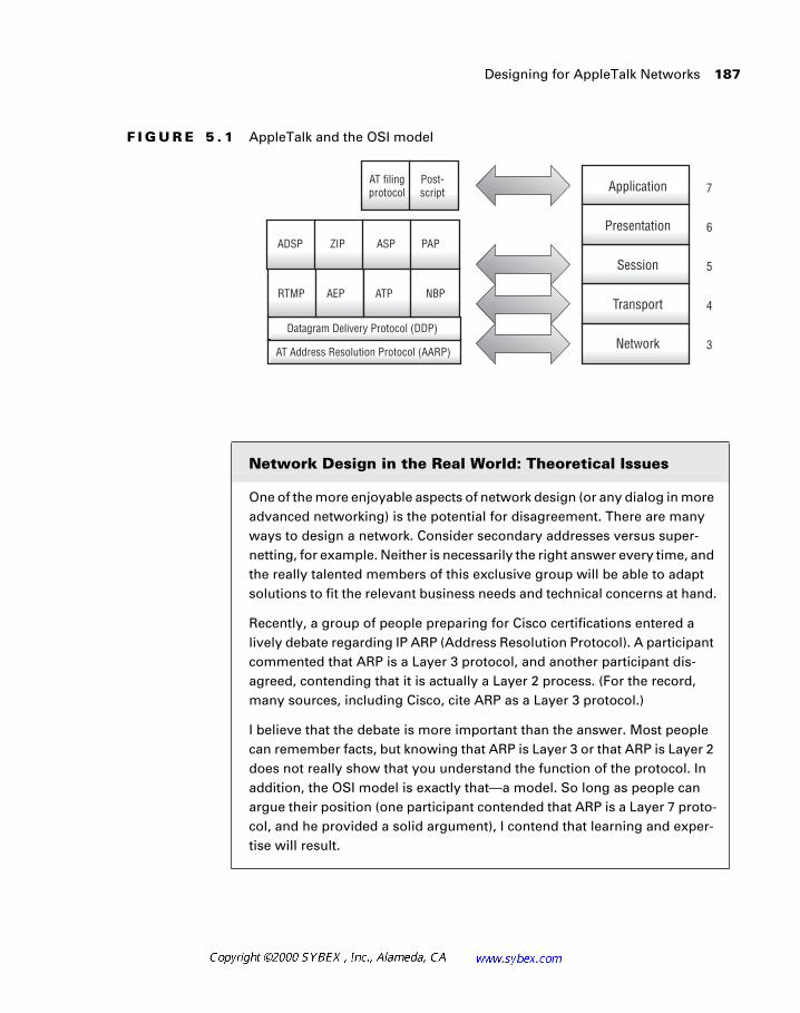
Designing for AppleTalk Networks 187
F I G U R E 5 . 1 AppleTalk and the OSI model
Network Design in the Real World: Theoretical Issues
One of the more enjoyable aspects of network design (or any dialog in more advanced networking) is the potential for disagreement. There are many ways to design a network. Consider secondary addresses versus super-netting, for example. Neither is necessarily the right answer every time, and the really talented members of this exclusive group will be able to adapt solutions to fit the relevant business needs and technical concerns at hand.
Recently, a group of people preparing for Cisco certifications entered a lively debate regarding IP ARP (Address Resolution Protocol). A participant commented that ARP is a Layer 3 protocol, and another participant dis-agreed, contending that it is actually a Layer 2 process. (For the record, many sources, including Cisco, cite ARP as a Layer 3 protocol.)
I believe that the debate is more important than the answer. Most people can remember facts, but knowing that ARP is Layer 3 or that ARP is Layer 2 does not really show that you understand the function of the protocol. In addition, the OSI model is exactly that—a model. So long as people can argue their position (one participant contended that ARP is a Layer 7 proto-col, and he provided a solid argument), I contend that learning and exper-tise will result.
188 Chapter 5 � Designing AppleTalk Networks
The following section provides additional information regarding the major AppleTalk protocols:
AppleTalk Address Resolution Protocol AARP performs two different functions in AppleTalk. First, it is responsible for mapping AppleTalk addresses to hardware addresses. This Layer 3 to Layer 2 mapping is similar to the ARP process in IP. Second, AARP handles the dynamic assignment of node addresses.
Datagram Delivery Protocol DDP provides unique addressing of all nodes on the AppleTalk internetwork and is responsible for connection-less delivery of datagrams between nodes. Also, DDP, in conjunction with AARP, provides the functions of Layer 3. DDP is responsible for connec-tivity to the upper-layer protocols, and AARP is tasked with connectivity to the lower layers.
Name-Binding Protocol NBP provides name-to-address resolution that is similar to DNS in TCP/IP. It also handles additional functions, includ-ing the population of names in the Chooser for resources on the network.
In the context of AppleTalk, Figure 5.1 illustrates the common relationship between AppleTalk protocols and the OSI model. Clearly, arguments could be raised that impact the actual placement of the protocols within the dia-gram. It is unlikely, though, that you will see a question worded on an exam as, “What Layer is X protocol?” However, you should be comfortable answer-ing such a question and defending your answer. Although the Cisco answer, for our purposes, is the right answer, that may not provide much comfort in a late-night troubleshooting session.
One additional note—surround yourself with as much talent as you can. Technology changes too fast to maintain expertise in every area all of the time. If you do this, you’re more likely to find a resource in your circle who is well-versed in the area in question. Today, for example, I discussed an Enhanced Interior Gateway Routing Protocol (EIGRP) migration for a large company with two colleagues. Everyone contributed, and all of us learned new things from the dialogue. Some of the lessons came from new ways to ask the questions rather than assuming the answer.
Designing for AppleTalk Networks 189
Routing Table Maintenance Protocol RTMP is AppleTalk’s default routing protocol. Updates are sent every 10 seconds, and routes are aged out of the table after 20 seconds, which can result in route flapping on congested segments as the RTMP updates are dropped.
Zone Information Protocol Zones are logical divisions of AppleTalk resources. ZIP maps zone names to network addresses. Although nodes belong to one zone, zones can span multiple physical networks.
When designing for the use of AppleTalk in most small- to medium-sized networks, the most significant issues will involve addressing and naming, which will be covered in this section. The next two sections will address those issues that frequently arise with larger networks—specifically, routing and scalability.
AppleTalk Addressing
The AppleTalk protocol was designed to limit the amount of technical expertise required to configure the workstation for operation on the net-work. As a result, the workstation has virtually no configuration options and obtains its address via a dynamic querying process.
In AppleTalk, the network administrator will assign a cable range, or block of addresses that the workstations will use. For our purposes, we will ignore the issues between AppleTalk phase one and phase two and assume the use of only phase two in this presentation. Recall that AppleTalk phase one does not permit cable ranges and allows for only 127 node addresses, as reflected in Table 5.1.
AppleTalk phase one is severely limited in scalability, and it is recommended that companies migrate to phase two if they have not already done so.
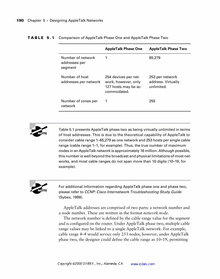
190 Chapter 5 � Designing AppleTalk Networks
Table 5.1 presents AppleTalk phase two as being virtually unlimited in terms of host addresses. This is due to the theoretical capability of AppleTalk to consider cable range 1–65,279 as one network and 253 hosts per single cable range (cable range 1–1, for example). Thus, the true number of maximum nodes in an AppleTalk network is approximately 16 million. Although possible, this number is well beyond the broadcast and physical limitations of most net-works, and most cable ranges do not span more than 10 digits (10–19, for example).
For additional information regarding AppleTalk phase one and phase two, please refer to CCNP: Cisco Internetwork Troubleshooting Study Guide (Sybex, 1999).
AppleTalk addresses are comprised of two parts: a network number and a node number. These are written in the format network.node.
The network number is defined by the cable range value for the segment and is configured on the router. Under AppleTalk phase two, multiple cable range values may be linked to a single AppleTalk network. For example, cable range 4–4 would service only 253 nodes; however, under AppleTalk phase two, the designer could define the cable range as 10–19, permitting
T A B L E 5 . 1 Comparison of AppleTalk Phase One and AppleTalk Phase Two
AppleTalk Phase One AppleTalk Phase Two
Number of network addresses per segment
1 65,279
Number of host addresses per network
254 devices per net-work, however, only 127 hosts may be ac-commodated.
253 per network address. Virtually unlimited.
Number of zones per network
1 255
Designing for AppleTalk Networks 191
hundreds of nodes. Note that these 10 cable ranges become a single log-ical network. This is comparable to expanding the mask in IP, but Apple-Talk networks do not share the concept of a separate net mask. For example, nodes on cable range 10–19 might appear as 14.91 and 17.132. In this case, both nodes are on the same network.
Cisco recommends that AppleTalk cable ranges follow some numerically significant schema, and more importantly, that administrators and designers document these numbers. Remember that the ranges cannot overlap and must remain unique within the network.
Some administrators assign network numbers based on the geography of the environment. A campus with five buildings might have four-digit cable range numbers. The first digit could relate to the building, the second to the floor within that building, and so on. Since there are over 64,000 network numbers available, the designer should be able to develop a numbering plan that is easy to understand, which will simplify troubleshooting.
As noted previously, the node number is a unique identifier of the device on the network. As a Layer 3 protocol, the network number is the routable portion of the address space—the node number is insignificant until the packet arrives on the local segment.
In addition to the network number and node number, there is a third sig-nificant parameter to the AppleTalk address: the socket number. Socket numbers in AppleTalk are very similar to socket numbers in TCP and UDP. They provide a specific interface on the node for communications. There-fore, the network-visible entries (NVEs) are identified by three addressing parameters: the 16-bit network number, the 8-bit node number, and the 8-bit socket number. Network-visible entries are network devices—a fancy term to describe a host, server, printer, or other element that might appear to the user.
AppleTalk Naming
One of the conveniences of AppleTalk is its use of names to identify resources within the network, which is not unlike the DNS and WINS (Win-dows Internet Naming Service) services in the IP world. However, unlike the two IP naming techniques, AppleTalk included naming in the initial protocol.
In fact, there are actually two names in the AppleTalk arena: the zone name and the resource name. Consider the zone name in the same manner
192 Chapter 5 � Designing AppleTalk Networks
you might think of a sub-domain name in the IP DNS structure. The main difference between the two naming schemes is that AppleTalk does not incorporate the idea of sub-domains and hierarchical structures. Alterna-tively, for those more familiar with Windows, AppleTalk is similar to the workgroup model. Resources are members of a grouping, but the grouping is only one of many equals—names in AppleTalk are flat. The DNS structure allows for names to traverse multiple layers—for example, the file server in Marketing in the fifth building in Dallas. AppleTalk designers are limited to using names such as Marketing or Marketing_Dallas for their structures.
From a design standpoint, zone names in AppleTalk are usually imple-mented with two parallel viewpoints in mind. The names need to be used by both the user community and the network administrators, and fortunately, in this instance, the solution will please both groups.
AppleTalk zone names are case sensitive. Nonetheless, there are instances when connectivity may appear to function correctly even though the router has the incorrect form of the name. Such an installation will eventually expe-rience some problem that will require resolution. Some designers use all lowercase names to avoid this issue.
Designers ideally will select zone names that reflect the departmental grouping related to each particular network, typically resulting in names like “Marketing” for the Marketing group and “Human Resources” for the Human Resources group. This naming scheme will help users locate the ser-vices provided by devices in each zone, and typically, these groups (depart-ments, like Human Resources) will be physically located in the same general area. Such a scheme will also further assist administrators, because trouble-shooting is simplified when the Marketing zone is no longer visible in the Chooser.
The Chooser is the service-selection tool in the Macintosh OS. It lists all zones in the network. Once the user selects a zone, all of the resources in that zone will be presented, and the user can select a resource within the zone.
One minor downside to the AppleTalk zone-naming scheme is that it relies on broadcasts to announce the presence of each zone. These names are propagated throughout the entire network, so a large network might have
Designing for AppleTalk Networks 193
hundreds of broadcasts every minute to cover all of the zones. In addition, each router summarizes all of the zones it knows about and advertises this information to the rest of the network, quickly adding to the load imposed by the process. Another minor downside is the somewhat limited number of zone names permitted in an AppleTalk network. The specification per-mits only 255 names, which could be a factor for the network designer to consider. In practice, designers should limit the number of zones to less than 100.
Do not place all WAN networks into a single zone. While AppleTalk supports multiple cable ranges per zone, it is best to limit each zone to a single cable range. Designers may wish to span a select number of zones for some service clusters.
Since the Chooser lists zone names in alphabetical order, most designers use a prefix of at least one “Z” when they want to move these zones to the bottom of the list. This tactic is very appropriate for WAN segments and other non-user-related zones.
Machine names in AppleTalk are generally a more difficult design issue, and many times they are omitted from the network design layer. This omis-sion is a double-edged sword, as a logical naming structure would greatly assist the inventory and troubleshooting processes. However, most Macin-tosh workstations are named for their users or another unique characteristic. For example, Apple names its routers for famous comedians and other fig-ures rather than using the perhaps more boring names Router_A and Router_B.
194 Chapter 5 � Designing AppleTalk Networks
The AppleTalk naming standard introduces a larger concept that has, as of yet, remained unaddressed in this text. The naming standard under any pro-tocol should be an important consideration for all network designers. While Daffy and Mickey might be cute names for routers, they fail to communicate their function or location. At the opposite extreme, router RC7500-B-ORD might clearly refer to Cisco router type 7500 at the second location (location B) in Chicago, but the name doesn’t exactly roll off the tongue, so to speak. Another danger with the more formal naming convention is that it might not scale as initially intended. For example, how would the designer name the router in the fifth Chicago location? ORD probably should not refer to routers in all five locations. (ORD stands for Orchard Field, the original name for Chicago O’Hare International airport.)
It is important for designers to compose naming conventions that provide unambiguous names for nodes. In AppleTalk, names are ultimately pre-sented in the format Node Name: Device Type@Zone. This format relates directly to the address information of the node, i.e., the zone name is the log-ical grouping of devices and the node name relates to a specific machine. The device type provides the socket information referenced earlier in this chapter. The device type might appear as Server:AFPServer@Sybex Sales. Cisco rec-ommends that user nodes be named for their user and that they be listed last name first to facilitate searching. Unlike some other platforms, Macintosh resources frequently serve as both client and server; therefore, there may be numerous device types for a particular resource.
The AppleTalk Chooser
The Chooser in Macintosh systems is similar to the Network Neighborhood in Windows networks. See Figure 5.2. Apple users utilize the Chooser to select files, print, and perform other services.
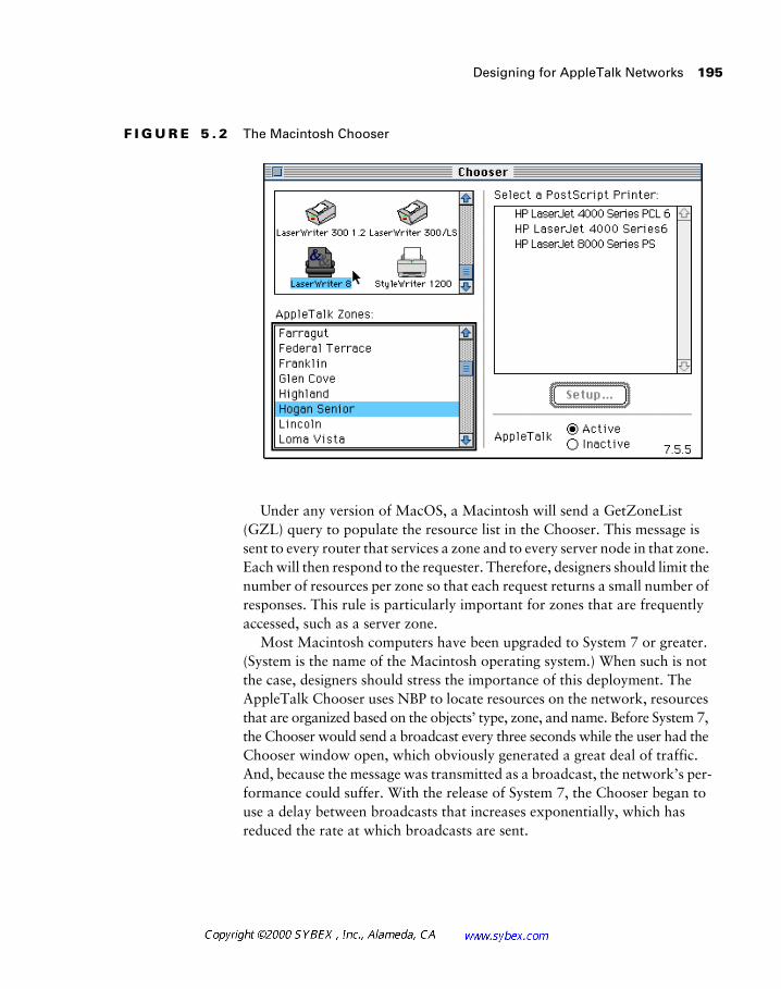
Designing for AppleTalk Networks 195
F I G U R E 5 . 2 The Macintosh Chooser
Under any version of MacOS, a Macintosh will send a GetZoneList (GZL) query to populate the resource list in the Chooser. This message is sent to every router that services a zone and to every server node in that zone. Each will then respond to the requester. Therefore, designers should limit the number of resources per zone so that each request returns a small number of responses. This rule is particularly important for zones that are frequently accessed, such as a server zone.
Most Macintosh computers have been upgraded to System 7 or greater. (System is the name of the Macintosh operating system.) When such is not the case, designers should stress the importance of this deployment. The AppleTalk Chooser uses NBP to locate resources on the network, resources that are organized based on the objects’ type, zone, and name. Before System 7, the Chooser would send a broadcast every three seconds while the user had the Chooser window open, which obviously generated a great deal of traffic. And, because the message was transmitted as a broadcast, the network’s per-formance could suffer. With the release of System 7, the Chooser began to use a delay between broadcasts that increases exponentially, which has reduced the rate at which broadcasts are sent.
196 Chapter 5 � Designing AppleTalk Networks
AppleTalk Routing Protocols
Dynamic routing within the AppleTalk environment may use a num-ber of protocols, which include AppleTalk RTMP, AppleTalk EIGRP (Enhanced Interior Gateway Routing Protocol), and AURP (AppleTalk Update-Based Routing Protocol). This section will introduce each of these along with information for designers to consider when selecting the appro-priate protocol for their environment.
While floating static routes are typically not incorporated into most AppleTalk designs, Cisco introduced the concept of floating static routes for AppleTalk in IOS version 11. This feature may be useful for designers when incorporating backup routes into the network.
AppleTalk RTMP
The default AppleTalk routing protocol is RTMP, which is very similar to the Routing Information Protocol (RIP) found in IP. Both protocols are limited to a hop count of 15, and AppleTalk always incorporates a split-horizon update mechanism. Unlike IP RIP, though, RTMP sends updates every 10 seconds. Updating so frequently significantly adds to the chatty rep-utation of the overall protocol. Updates appear in the form of “tuples,” which contain the cable range and hop count values.
The designer must consider a number of factors with RTMP. First, net-works are limited to 15 hops due to the requirements of the routing protocol. This limitation may not be a large concern, as a well-designed network should rarely need 15 hops between networks, but the limitation remains and is a factor in the design. Second, RTMP is very chatty, as noted before, and so the designer may wish to use another protocol to conserve bandwidth and resources. However, this option is not always available because work-stations and servers need to hear updates in order to operate on the network. Consequently, populated segments do not have RTMP disabled.
The designer should also consider the following with regard to AppleTalk RTMP packets:
� RTMP transmits every 10 seconds by default.
� An RTMP packet can contain up to 100 tuples.
� Each RTMP packet can be up to 600 bytes long (DDP).
� A tuple is created for each AppleTalk cable range.
AppleTalk Routing Protocols 197
By using this information, the designer may calculate the impact that rout-ing updates have on the network. This impact is especially important on low-speed WAN links, where bandwidth may be severely limited. It is clear that a large routing table, transmitted every 10 seconds in its entirety, would quickly consume a substantial percentage of the bandwidth on a 56Kbps circuit.
Partial-mesh networks are also thwarted by the demands of split-horizon updates in RTMP. As a result, designers will need to use full-mesh topologies or consider the other two routing protocols, AT EIGRP or AURP. The EIGRP version of AppleTalk is perhaps best suited to address this problem.
AppleTalk EIGRP
As with all of the EIGRP routing protocols, the AppleTalk EIGRP (AT EIGRP) is proprietary to Cisco and requires the administrator to commit to an all-Cisco solution. For some environments, this restriction does not pose a significant shortcoming, and the use of AT EIGRP can greatly enhance the scalability of the AppleTalk protocol.
Unlike EIGRP for the IP and IPX protocols, AT EIGRP does not use the same autonomous system (AS) or process identifier for all routers in the network. In fact, the AT EIGRP identifier must be different for each router in the network that will participate in AT EIGRP. This requirement is an important design and documentation consideration that should be incorporated into the addressing and naming convention. In addition, the number following the AT EIGRP com-mand, appletalk routing eigrp router-number, is not an AS number but a router-number, as shown.
As noted in the previous section, the default AppleTalk routing protocol, RTMP, does not scale well. This is due to its 15-hop-count limitation and its frequent broadcasts of the entire routing table. In addition, the required use of split-horizon updates can limit designs that use partial-mesh configura-tions. This limitation is negated with the use of AT EIGRP.
The exclusive use of AT EIGRP is most appropriate on WAN links. None-theless, it may also be used in the backbone and other transit segments that do not require RTMP updates. When enabling AT EIGRP, the router will automatically redistribute route information between AT EIGRP and RTMP. The most significant benefits to AT EIGRP are its conservation of
198 Chapter 5 � Designing AppleTalk Networks
bandwidth (updates occur only following a network change) and rapid con-vergence (under one second following a link failure). Of course, convergence times within the RTMP environment will be limited by that protocol.
It’s important to keep in mind that Apple devices cannot be placed in AT EIGRP-only segments because they must receive RTMP updates.
To calculate the metric in AT EIGRP, the router employs a simple formula that makes each hop appear as a 9,600bps link. The RTMP hop count infor-mation is preserved.
The formula used is as follows:AT EIGRP metric = number of hops × 25652400As noted in the AppleTalk RTMP section, RTMP is limited in partial-
mesh network designs because of the requirement that split-horizon must always be used. In AT EIGRP, this requirement no longer exists, and so RTMP may, therefore, be better suited for such designs as these. The com-mand to remove split-horizon from AT EIGRP networks is no appletalk eigrp-splithorizon.
AURP
No, someone didn’t just lose their lunch. AURP specifies a standard way of connecting AppleTalk networks over point-to-point lines, including dial-up modems and T1 lines. More importantly, it provides a specification for tun-neling AppleTalk through foreign network systems, such as TCP/IP, X.25, OSI, and DECnet.
AURP also reduces routing update traffic. As opposed to the default 10-second update interval of RTMP, AURP updates routing tables only when a network change occurs. These updates include changes only to the topology and not the entire routing table, which further reduces the volume of traffic on the WAN link. Another benefit to the protocol is that it is an open stan-dard under the Internet Engineering Task Force (IETF), which makes it well suited to multivendor environments. The same is not true with AT EIGRP.
Designers should remember the following when considering AURP:
� The protocol is standards based.
� AURP does not replace RTMP.
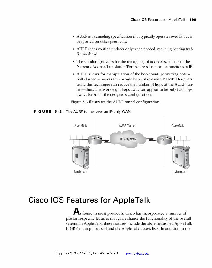
Cisco IOS Features for AppleTalk 199
� AURP is a tunneling specification that typically operates over IP but is supported on other protocols.
� AURP sends routing updates only when needed, reducing routing traf-fic overhead.
� The standard provides for the remapping of addresses, similar to the Network Address Translation/Port Address Translation functions in IP.
� AURP allows for manipulation of the hop count, permitting poten-tially larger networks than would be available with RTMP. Designers using this technique can reduce the number of hops at the AURP tun-nel—thus, a network eight hops away can appear to be only two hops away, based on the designer’s configuration.
Figure 5.3 illustrates the AURP tunnel configuration.
F I G U R E 5 . 3 The AURP tunnel over an IP-only WAN
Cisco IOS Features for AppleTalk
As found in most protocols, Cisco has incorporated a number of platform-specific features that can enhance the functionality of the overall system. In AppleTalk, these features include the aforementioned AppleTalk EIGRP routing protocol and the AppleTalk access lists. In addition to the
AppleTalk AppleTalkAURP Tunnel
Macintosh Macintosh
IP-only WAN
200 Chapter 5 � Designing AppleTalk Networks
typical Cisco access list, a number of protocol-specific access lists are avail-able to the designer, including ZIP filters and NBP filters. These will be pre-sented in this section.
AppleTalk Access Lists
AppleTalk access lists operate in much the same way as they do in IP or other routing protocols. Therefore, the administrator or designer may use them to create distribute lists that control RTMP packets and block cable ranges. They may also be used as part of a security model.
It is important to note that there are additional filters in AppleTalk that are specifically designed to handle certain restrictions in AppleTalk net-works. These are presented in this section, and the designer should use them when appropriate. For example, you should not use distribute lists to block zone information. Doing so may cause problems within the network. It is best to use the ZIP reply filter or the GetZoneList filter. All of these filters are based on AppleTalk access lists.
AppleTalk Zone Information
Zone Information Protocol (ZIP) packets advertise zone information to the network. This information must relate to the route, or routes, that corre-sponds to a particular zone. When ZIP advertises information about a route that does not have a corresponding zone, it can cause a ZIP storm. Cisco routers prevent ZIP storms by holding routing updates for networks that have not sent corresponding zone information. In so doing, the potential for ZIP storms is greatly reduced. Note that this feature greatly increases the sta-bility of the network, but it may slow the propagation of route information.
AppleTalk ZIP Reply Filters
Available since Cisco IOS 10.2, AppleTalk ZIP reply filters can be an effec-tive mechanism for blocking zone information at the router. This action may be warranted at a border router between two organizations, but AppleTalk is typically not shared between organizations. Rather, the function is used to
Cisco IOS Features for AppleTalk 201
control zone information between different divisions within the company—either on departmental or geographical boundaries. In all cases, this function is employed between administrative domains.
The ZIP reply filter does not affect RTMP updates between routers but does squelch the ZIP reply to the corresponding ZIP request, effectively hid-ing the zones from the opposing network. The network, or cable range, asso-ciated with that zone will also be removed from the routing table, since there is no associated zone name.
A separate function available to AppleTalk designers is the free-trade zone. This zone may be created between two organizations or two parts of the same domain. In both cases, networks on either side of the free-trade zone are blocked from the other.
The command that applies the ZIP reply filter is appletalk zip-reply-filter.
AppleTalk GetZoneList Filters and NBP Filters
It is possible to limit the zone information presented to a group of users with GetZoneList filters. This mechanism may be used to provide limited security or to simplify a portion of the network.
The administrator places the GetZoneList filter on the router that services the users. The filter must be placed on every cable range that user nodes use to access the network. This placement requirement limits the scalability of this function. The filter operates by responding to GetZoneList queries with a parsed version of the network zone list.
The NBP filters were introduced with version 11 of the IOS and are used to block specific services from hosts.
The commands that relate to GetZoneList and NBP filters as shown in Table 5.2.
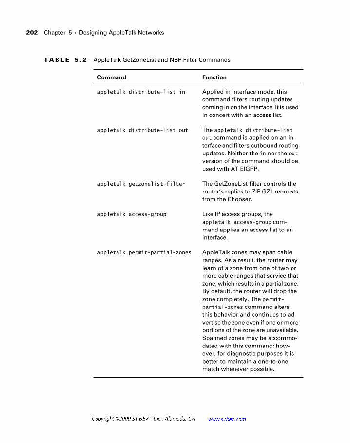
202 Chapter 5 � Designing AppleTalk Networks
T A B L E 5 . 2 AppleTalk GetZoneList and NBP Filter Commands
Command Function
appletalk distribute-list in Applied in interface mode, this command filters routing updates coming in on the interface. It is used in concert with an access list.
appletalk distribute-list out The appletalk distribute-list out command is applied on an in-terface and filters outbound routing updates. Neither the in nor the out version of the command should be used with AT EIGRP.
appletalk getzonelist-filter The GetZoneList filter controls the router’s replies to ZIP GZL requests from the Chooser.
appletalk access-group Like IP access groups, the appletalk access-group com-mand applies an access list to an interface.
appletalk permit-partial-zones AppleTalk zones may span cable ranges. As a result, the router may learn of a zone from one of two or more cable ranges that service that zone, which results in a partial zone. By default, the router will drop the zone completely. The permit-partial-zones command alters this behavior and continues to ad-vertise the zone even if one or more portions of the zone are unavailable. Spanned zones may be accommo-dated with this command; how-ever, for diagnostic purposes it is better to maintain a one-to-one match whenever possible.
Cisco IOS Features for AppleTalk 203
AppleTalk Tunnels with GRE
There are instances where the designer may wish to use a single protocol in the network backbone, and with increasing frequency that protocol is IP. However, if the corporation needs to connect two or more AppleTalk seg-ments using the backbone, this problem is resolved with AppleTalk tunnel-ing, wherein the AppleTalk packets are encapsulated in another protocol.
Tunneling is typically an encapsulation of one protocol inside another—in this specific instance, AppleTalk inside of IP. There are two tunneling encapsulations: Generic Routing Encapsulation (GRE) and Cayman. Cayman is used when connecting a Cisco router to a GatorBox, and GRE is used when connecting two Cisco routers. This section will focus only on GRE.
From a logical perspective, tunnels are point-to-point links. As such, each link requires the creation of a separate tunnel. Note that GRE tunnels are not AURP tunnels (although they are similar). GRE tunnels do not encompass a routing process like AURP, for example.
Designers should consider the negatives of using tunnels versus using two protocols on the backbone and configuring the AppleTalk protocol. The fol-lowing list should assist in this evaluation:
� With tunnels, performance is decreased.
� Tunnels require additional configuration.
� Tunnels add overhead to both packets and processor utilization.
� Tunnels permit maintenance of a single protocol in the backbone, which may simplify configuration and troubleshooting within the core.
� AppleTalk tunnels should be deployed in star topologies to connect isolated LANs.
� If tunnels are not used, designers should evaluate AT EIGRP in the core along with the deployment of AppleTalk.
204 Chapter 5 � Designing AppleTalk Networks
Network Design in the Real World: Tunnels
While tunnels are a possible way to solve many design problems, it seems as though most architects are migrating away from this solution. The pri-mary reasons for this involve training and supportability. The installation of a tunnel is fairly straight-forward; however, it becomes substantially more complex as the number of tunnels increases. In addition, diagnostic pro-cesses no longer follow the intraprotocol methodologies that many techni-cians learned and employed. Rather than troubleshooting an AppleTalk problem, the administrator must add a diagnostic step to troubleshoot the IP portion and confirm that fragmentation and routing for the IP protocol is functioning correctly. As a result, it’s best to consider the arguments for and against using tunnels and then establish a policy for your installation if you decide to go ahead with them—like potato chips, you can’t have just one tunnel.
Some of the issues you should consider include:
Documentation—Will your team update and maintain a complete listing of all tunnels and their functions?
Troubleshooting—Does the expertise exist in all layers of the organization to troubleshoot tunnels and their problems? This answer requires knowl-edge of both protocols in use (the encapsulation and the native) and the hops between the end points of the tunnel.
Solvability—Unrelated to AppleTalk, one environment that I’m familiar with used tunnels to address subnets that are not contiguous with Interior Gate-way Routing Protocol (IGRP). The ultimate solution was to migrate to EIGRP and complete an addressing project that seemed to extend forever. Most of the staff contended correctly that tunnels are a dirty patch to a chronic prob-lem and that the company needed to invest in the resources to directly address the root cause. Ultimately, the scope grew to incorporate the orig-inal fixes and the removal of over fifty tunnels.
Scalability—This is included here because it is one of the bastions of net-work design; however, it really reverts back to solvability. Does the use of a tunnel solve a problem that cannot be resolved any other way?
Cisco IOS Features for AppleTalk 205
Macintosh IP
Macintosh IP (MacIP) was an interesting protocol, albeit a short-lived one. Rather than providing an IP stack, MacIP acted, more accurately, as a proxy or gateway. While most modern installations use a fully compliant version of the IP stack for the Macintosh, MacIP software allowed IP connectivity over the lower-level DDP protocol and required the command appletalk macip for operability on Cisco routers.
MacIP was most frequently configured to support LocalTalk or Apple-Talk Remote Access (ARA). These installations required MacIP in order to permit clients access to IP resources. LocalTalk was a low-bandwidth net-working solution that preceded AppleTalk. ARA is still used in some instal-lations, and it was an efficient means of connecting Macintosh devices to the network via a modem.
Configuration of MacIP required the following:
� Packets between Macintosh clients and IP hosts had to pass through the router if the client was configured to use it as a MacIP server. This design could add overhead and an extra hop when the two nodes resided on the same subnet.
� Router memory usage increased proportionally to the total number of active MacIP clients, consuming approximately 80 bytes per client.
� In addition, the router had to be configured as follows:
� AppleTalk routing had to be enabled on at least one interface.
� At least one interface had to be configured for IP routing.
� The MacIP zone name configured had to be associated with a con-figured or seeded zone name.
� The MacIP server had to reside within the AppleTalk zone.
� An IP address specified to the MacIP server using the appletalk macip command had to be associated with a specific IP interface on the router. The IP address had to be one to which ARP could respond.
� Any access list for IP had to apply to MacIP sessions.
206 Chapter 5 � Designing AppleTalk Networks
AppleTalk Interoperability
This chapter has already addressed a number of AppleTalk interoper-ability issues, including tunneling and the AppleTalk version of EIGRP. However, there are a few other items to keep in mind.
First, while AppleTalk generates a significant number of broadcasts in the network, the impact of other protocols on AppleTalk-only nodes is greatly reduced. Stated another way, IP and IPX broadcasts are discarded by AppleTalk-only devices at an earlier point than broadcasts in other protocols. In fact, AppleTalk-only stacks will discard all packets from all other Layer 3 protocols.
Second, the number of broadcasts in AppleTalk will significantly impact other devices on the network. Both IP and IPX stacks will process AppleTalk broadcasts like any other broadcast. Therefore, adding IP to Macintosh sys-tems or running IPX- and IP-based PCs on segments with AppleTalk devices will greatly magnify the impact of broadcasts.
In most current networks, designers have removed, or are in the process of removing, AppleTalk. Where AppleTalk segments remain, the general guideline is to use less than 200 nodes to populate a segment.
Summary
The AppleTalk protocol is perhaps one of the most user-friendly net-working protocols ever developed. Unfortunately, the scalability limitations of the protocol and the impact of the Internet (with its implied dependence on IP) have restricted its usage.
In this context, this chapter addressed the issues that confront network designers using AppleTalk in both large and small networks and also sug-gested methods by which the designer might address the limitations of the RTMP protocol. This might include the use of AppleTalk EIGRP, access lists, and specific naming and addressing conventions.
In addition, this chapter addressed some of the enhancements to the AppleTalk protocol, including AURP and the efficiency of using MacOS ver-sion 7. Also, filters specific to AppleTalk were reviewed.
Readers should be fairly comfortable with the features and benefits of AURP and AT EIGRP as they relate to the default RTMP as well. The oper-ations of the Chooser in AppleTalk networks are also important concepts to understand.
Review Questions 207
Review Questions
1. Which of the following are limitations of the AppleTalk protocol?
A. No hierarchical addressing scheme
B. No hierarchical naming scheme
C. High dependence on broadcasts
D. All of the above
2. When using the AppleTalk version of EIGRP, what unique convention must be followed?
A. The same AS number must be used on all routers in the domain.
B. Different process numbers must be used on each router in the domain.
C. RTMP must have the same AS number as AT EIGRP.
D. There is no version of AppleTalk EIGRP.
3. To connect two AppleTalk networks across an IP-only backbone, the designer must use which of the following?
A. AppleTalk tunnels
B. ZIP—Zone over IP
C. AT CGMP
D. AppleTalk cannot traverse IP-only segments.
4. Which of the following would be a valid AppleTalk cable range?
A. 4–4
B. Marketing_Zone
C. 10.12
D. 4–10
208 Chapter 5 � Designing AppleTalk Networks
5. Which of the following might be used to block zone information from reaching another AppleTalk administration domain?
A. AppleTalk EIGRP
B. AppleTalk RTMP
C. AppleTalk ZIP reply filters
D. AURP
6. In order to reduce traffic on WAN links, designers should:
A. Use AT EIGRP with route summarization enabled.
B. Use AURP.
C. Use RTMP.
D. Use RTMP on the WAN and AURP on the LAN.
7. How many updates may be included in an RTMP packet?
A. 25
B. 50
C. 100
D. 256
8. In order to simplify troubleshooting AppleTalk networks, designers should:
A. Design cable ranges that are numerically significant
B. Use MacOS version 7 or greater
C. Use RTMP
D. Use AT EIGRP

Review Questions 209
9. Network designers should work with the workstation administrators to:
A. Configure WINS servers for AppleTalk segments
B. Disable the Chooser Scanning Protocol (CSP)
C. Use MacIP whenever possible
D. Upgrade all workstations to a minimum of System 7
10. True or false, AURP and AppleTalk GRE tunnels are the same.
A. True
B. False
11. Before System 7, the Chooser requested zone information how frequently?
A. Every 3 seconds
B. Every 5 seconds
C. Every 10 seconds
D. Every 60 seconds
12. Two devices are addressed as 4.5 and 7.9, respectively. Are they in the same network if the cable range is 1–9?
A. Yes
B. No
13. Which routing protocol sends updates only?
A. ZIP
B. RTMP
C. AURP
D. None of the above
210 Chapter 5 � Designing AppleTalk Networks
14. Which of the following is true regarding MacIP?
A. It is a compliant IP stack for interoperating with non-Macintosh systems.
B. It provides TN3270 emulation.
C. It is faster than TCP/IP for file transfers.
D. It is similar to a proxy service.
15. Which of the following is a reason to use tunnels for AppleTalk?
A. Additional overhead and processing
B. Transport of AppleTalk over IP-only networks
C. Additional security
D. Compatibility with CDP
16. Node number 231 is on cable range 50–59. Which of the following is a possible AppleTalk address?
A. 50.59
B. 231.51
C. 50–59
D. 56.231
17. Cisco recommends that nodes follow which naming convention?
A. User name, last name first
B. User name, first name first
C. Same as AppleTalk address
D. Named for famous people
Review Questions 211
18. AppleTalk network numbers should:
A. Be assigned sequentially
B. Always start with a one
C. Relate to a location, possibly using a site, building, and floor office model
D. Be the same for all WAN segments
19. Which of the following is not true regarding MacIP?
A. It requires at least one IP network.
B. It requires at least one AppleTalk network.
C. The MacIP server must be in the AppleTalk network.
D. It operates only with AppleTalk Remote Access (ARA).
20. AppleTalk tunnels are best configured in:
A. Star configurations
B. Ring configurations
C. Hierarchical configurations
D. None of the above. Tunnels are available only on point-to-point serial links.
212 Chapter 5 � Designing AppleTalk Networks
Answers to Review Questions
1. D.
2. B.
3. A.
4. A, D.
5. C.
6. B.
7. C.
8. A.
9. D.
10. B.
11. A.
12. A.
13. C.
14. D.
15. B.
Some designers may note that tunnels can be encrypted, thus aug-menting security. However, enhanced security is not a primary reason to use tunnels for AppleTalk in this context.
16. D.
17. A.
18. C.
19. D.
20. A.
Chapter
6Designing Networks with Novell and IPX
CISCO INTERNETWORK DESIGN EXAM OBJECTIVES COVERED IN THIS CHAPTER:
� Use Enhanced IGRP for path determination in internetworks
that support IP, IPX, and AppleTalk.
� Examine a client’s requirements and construct an appropriate
IPX design solution.
� Choose the appropriate routing protocol for an IPX
internetwork.
� Design scalable and manageable IPX internetworks by
controlling RIP and SAP traffic.
For many years, Novell’s IPX protocol commanded a signifi-cant share of the networking market. However, like AppleTalk, Novell’s IPX protocol is being replaced with TCP/IP in most modern networks.
As with AppleTalk, IPX was designed to simplify administrative functions and avoid some of the manual, complex tasks that were required by admin-istrators and designers. For example, IPX does not incorporate the concept of subnets, which negates the need for calculating subnet masks or pre-limiting the number of hosts that will be supported by the network. This is both a positive and a negative—administrators need to configure the net-work address only once and all workstations will automatically learn this information. However, this automation adds to the total overhead.
This chapter will address many of the common issues that arise when designing IPX networks, and it will also provide some direction to creating a scalable design.
The IPX Protocol
As noted at the beginning of this chapter, Novell’s IPX protocol was designed to simplify the configuration of the network. While this chapter will document some of the penalties that came from these features, it is important for designers to be aware of how these features differ from IP and how they may benefit from using IPX. Table 6.1 compares the IP and IPX protocols.
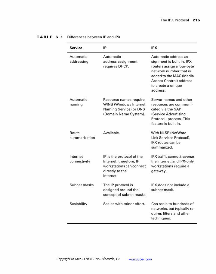
The IPX Protocol 215
T A B L E 6 . 1 Differences between IP and IPX
Service IP IPX
Automatic addressing
Automatic address assignment requires DHCP.
Automatic address as-signment is built in. IPX routers assign a four-byte network number that is added to the MAC (Media Access Control) address to create a unique address.
Automatic naming
Resource names require WINS (Windows Internet Naming Service) or DNS (Domain Name System).
Server names and other resources are communi-cated via the SAP (Service Advertising Protocol) process. This feature is built in.
Route summarization
Available. With NLSP (NetWare Link Services Protocol), IPX routes can be summarized.
Internet connectivity
IP is the protocol of the Internet; therefore, IP workstations can connect directly to the Internet.
IPX traffic cannot traverse the Internet, and IPX-only workstations require a gateway.
Subnet masks The IP protocol is designed around the concept of subnet masks.
IPX does not include a subnet mask.
Scalability Scales with minor effort. Can scale to hundreds of networks, but typically re-quires filters and other techniques.
216 Chapter 6 � Designing Networks with Novell and IPX
In modern network design, it is increasingly unlikely for designers to select IPX because of Novell’s support for IP and the growth of the Internet. Many designers prefer to use a single network protocol when possible, and the most-supported protocol is IP. However, legacy networks may incorpo-rate large installations of IPX, and there are still applications that may war-rant its deployment.
This chapter will focus on the IPX protocol on Novell servers, but it is important to note that Novell also supports NFS (Network File System) for Unix systems and AFP (AppleTalk File Protocol) for Apple systems on the server. This is in addition to the native NCP (NetWare Core Protocol) run-ning on IPX. Novell also supports gateway services for mainframes with its SAA (Systems Application Architecture) gateway product.
Cisco and Novell recommend that individual IPX networks contain no more than 500 nodes. This limitation results from the broadcast traffic inherent in IPX designs. In practice, this value is fairly high—most IPX envi-ronments experience degradation at the 200-to-300-node level.
In production networks, do not use the broadcast percentage to evaluate the health of the network. Broadcasts-per-second values provide a clearer indica-tion of how the broadcasts are affecting the users.
Also, note that Cisco routers typically require the configuration of an IPX internal network number for NLSP and other services within the Novell environment. As with other network numbers, the internal network number must be unique within the internetwork.
IPX RIP and SAP
Novell IPX employs a routing protocol similar to IP RIP, which is transmit-ted every 60 seconds (as opposed to every 30 seconds) and may contain up to 50 different network entries per update packet. The network diameter is still limited to 15 hops when using IPX RIP, the same as with IP RIP.
While there are many similarities between IP RIP and IPX RIP, please note that they are different routing protocols.
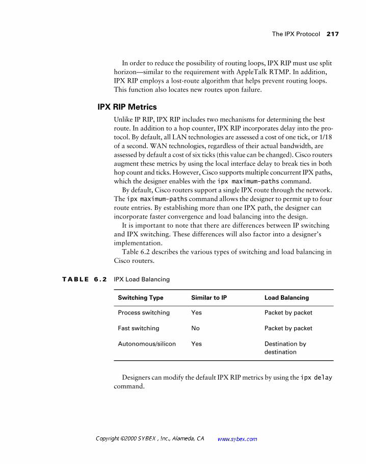
The IPX Protocol 217
In order to reduce the possibility of routing loops, IPX RIP must use split horizon—similar to the requirement with AppleTalk RTMP. In addition, IPX RIP employs a lost-route algorithm that helps prevent routing loops. This function also locates new routes upon failure.
IPX RIP Metrics
Unlike IP RIP, IPX RIP includes two mechanisms for determining the best route. In addition to a hop counter, IPX RIP incorporates delay into the pro-tocol. By default, all LAN technologies are assessed a cost of one tick, or 1/18 of a second. WAN technologies, regardless of their actual bandwidth, are assessed by default a cost of six ticks (this value can be changed). Cisco routers augment these metrics by using the local interface delay to break ties in both hop count and ticks. However, Cisco supports multiple concurrent IPX paths, which the designer enables with the ipx maximum-paths command.
By default, Cisco routers support a single IPX route through the network. The ipx maximum-paths command allows the designer to permit up to four route entries. By establishing more than one IPX path, the designer can incorporate faster convergence and load balancing into the design.
It is important to note that there are differences between IP switching and IPX switching. These differences will also factor into a designer’s implementation.
Table 6.2 describes the various types of switching and load balancing in Cisco routers.
Designers can modify the default IPX RIP metrics by using the ipx delay command.
T A B L E 6 . 2 IPX Load Balancing
Switching Type Similar to IP Load Balancing
Process switching Yes Packet by packet
Fast switching No Packet by packet
Autonomous/silicon Yes Destination by destination
218 Chapter 6 � Designing Networks with Novell and IPX
Do not infer from Table 6.2 that IPX cannot be fast-switched—it can. Its behav-ior is different from the characteristics of IP fast switching. Also note that some versions of the IOS, including 11.2(12), have problems with IPX fast switching, and administrators should upgrade their routers as applicable.
Controlling IPX SAP Traffic
The Service Advertising Protocol, or SAP, is responsible for the distribu-tion of information regarding file, print, and other services provided by the network.
For the network designer, the SAP process can be both a help and a hin-drance. The most significant problem with SAPs is their reliance on broad-casts, which in turn limits scalability.
However, it is not the broadcast update mechanism that hinders scalabil-ity with SAP. The issue is the method used to create the updates. Each router and server in the network recalculates SAP traffic. This information is then retransmitted as a complete SAP table, which should be consistent through-out the network. Rather than sending information about just the services that that server provides, the device sends information about all services that all devices provide. Also, separate SAP entries are created for each service, so a NetWare server with three printers, file sharing, and four database entries would create eight SAP entries—requiring two SAP packets.
Each SAP update is transmitted at 60-second intervals, and each update packet contains up to seven services. The designer can readily see how the addition of a single service on the network would add to the SAP traffic when repeated by 1,000 routers and servers, for example.
It is important for the network designer to consider filtering IPX SAP traf-fic even when the network is quite small—possibly as small as 20 networks. The use of IPX SAP access lists can provide security and scalability features to the network. As with most network policies, SAP access lists are best deployed at the distribution layer of the hierarchical model.
Table 6.3 shows the three different locations where administrators may employ SAP access lists.
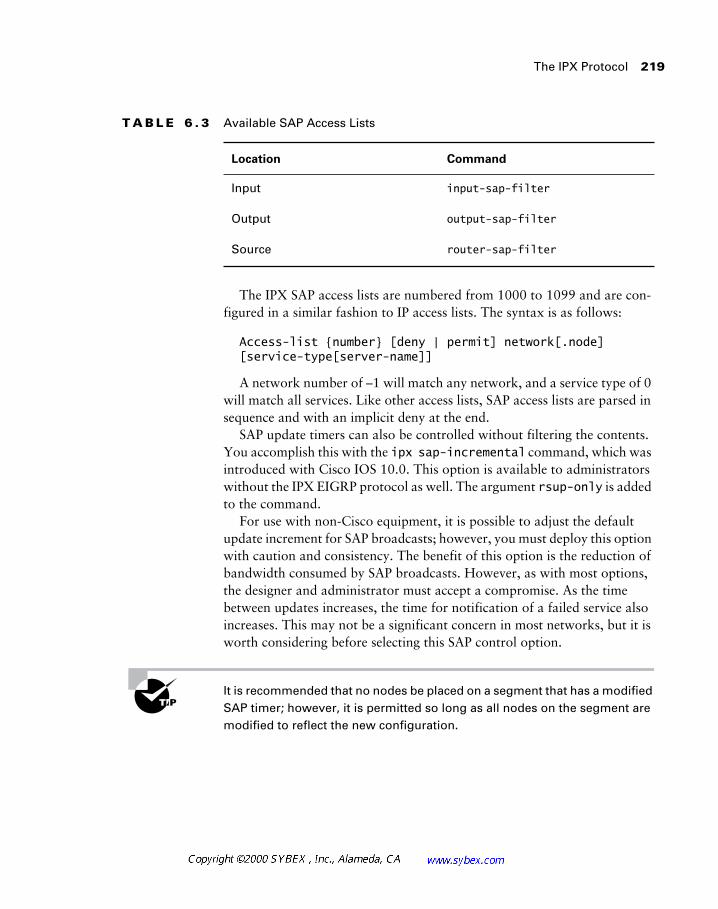
The IPX Protocol 219
The IPX SAP access lists are numbered from 1000 to 1099 and are con-figured in a similar fashion to IP access lists. The syntax is as follows:
Access-list {number} [deny | permit] network[.node] [service-type[server-name]]
A network number of –1 will match any network, and a service type of 0 will match all services. Like other access lists, SAP access lists are parsed in sequence and with an implicit deny at the end.
SAP update timers can also be controlled without filtering the contents. You accomplish this with the ipx sap-incremental command, which was introduced with Cisco IOS 10.0. This option is available to administrators without the IPX EIGRP protocol as well. The argument rsup-only is added to the command.
For use with non-Cisco equipment, it is possible to adjust the default update increment for SAP broadcasts; however, you must deploy this option with caution and consistency. The benefit of this option is the reduction of bandwidth consumed by SAP broadcasts. However, as with most options, the designer and administrator must accept a compromise. As the time between updates increases, the time for notification of a failed service also increases. This may not be a significant concern in most networks, but it is worth considering before selecting this SAP control option.
It is recommended that no nodes be placed on a segment that has a modified SAP timer; however, it is permitted so long as all nodes on the segment are modified to reflect the new configuration.
T A B L E 6 . 3 Available SAP Access Lists
Location Command
Input input-sap-filter
Output output-sap-filter
Source router-sap-filter
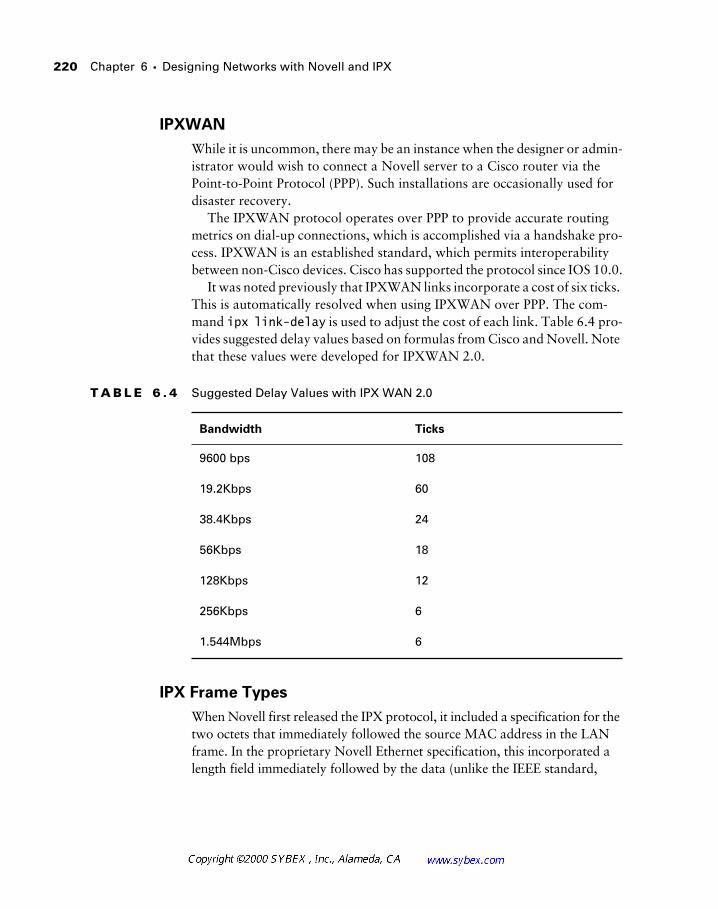
220 Chapter 6 � Designing Networks with Novell and IPX
IPXWAN
While it is uncommon, there may be an instance when the designer or admin-istrator would wish to connect a Novell server to a Cisco router via the Point-to-Point Protocol (PPP). Such installations are occasionally used for disaster recovery.
The IPXWAN protocol operates over PPP to provide accurate routing metrics on dial-up connections, which is accomplished via a handshake pro-cess. IPXWAN is an established standard, which permits interoperability between non-Cisco devices. Cisco has supported the protocol since IOS 10.0.
It was noted previously that IPXWAN links incorporate a cost of six ticks. This is automatically resolved when using IPXWAN over PPP. The com-mand ipx link-delay is used to adjust the cost of each link. Table 6.4 pro-vides suggested delay values based on formulas from Cisco and Novell. Note that these values were developed for IPXWAN 2.0.
IPX Frame Types
When Novell first released the IPX protocol, it included a specification for the two octets that immediately followed the source MAC address in the LAN frame. In the proprietary Novell Ethernet specification, this incorporated a length field immediately followed by the data (unlike the IEEE standard,
T A B L E 6 . 4 Suggested Delay Values with IPX WAN 2.0
Bandwidth Ticks
9600 bps 108
19.2Kbps 60
38.4Kbps 24
56Kbps 18
128Kbps 12
256Kbps 6
1.544Mbps 6
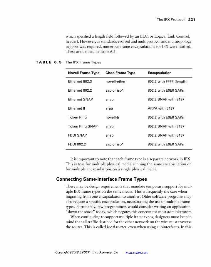
The IPX Protocol 221
which specified a length field followed by an LLC, or Logical Link Control, header). However, as standards evolved and multiprotocol and multitopology support was required, numerous frame encapsulations for IPX were ratified. These are defined in Table 6.5.
It is important to note that each frame type is a separate network in IPX. This is true for multiple physical media running the same encapsulation or for multiple encapsulations on a single physical media.
Connecting Same-Interface Frame Types
There may be design requirements that mandate temporary support for mul-tiple IPX frame types on the same media. This is frequently the case when migrating from one encapsulation to another. Older software programs may also require a specific encapsulation, necessitating the use of multiple frame types. Fortunately, few programmers would consider writing an application “down the stack” today, which negates this concern for most administrators.
When configuring to support multiple frame types, designers must keep in mind that all traffic destined for the other network on the wire must traverse the router. This is called local router, even when using subinterfaces. In this
T A B L E 6 . 5 The IPX Frame Types
Novell Frame Type Cisco Frame Type Encapsulation
Ethernet 802.3 novell-ether 802.3 with FFFF (length)
Ethernet 802.2 sap or iso1 802.2 with E0E0 SAPs
Ethernet SNAP snap 802.2 SNAP with 8137
Ethernet II arpa ARPA with 8137
Token Ring novell-tr 802.2 with E0E0 SAPs
Token Ring SNAP snap 802.2 SNAP with 8137
FDDI SNAP snap 802.2 SNAP with 8137
FDDI 802.2 sap or iso1 802.2 with E0E0 SAPs
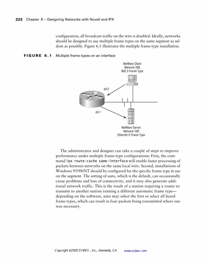
222 Chapter 6 � Designing Networks with Novell and IPX
configuration, all broadcast traffic on the wire is doubled. Ideally, networks should be designed to use multiple frame types on the same segment as sel-dom as possible. Figure 6.1 illustrates the multiple frame-type installation.
F I G U R E 6 . 1 Multiple frame types on an interface
The administrator and designer can take a couple of steps to improve performance under multiple frame-type configurations: First, the com-mand ipx route-cache same-interface will enable faster processing of packets between networks on the same local wire. Second, installations of Windows 95/98/NT should be configured for the specific frame type in use on the segment. The setting of auto, which is the default, can occasionally cause problems and loss of connectivity, and it may also generate addi-tional network traffic. This is the result of a station requiring a router to transmit to another station running a different automatic frame type—depending on the software, auto may select the first or select all heard frame types, which can result in four packets being transmitted where one was necessary.
NetWare ClientNetwork 200
802.3 Frame Type
NetWare ServerNetwork 100
Ethernet II Frame Type
e0.1
e0.2
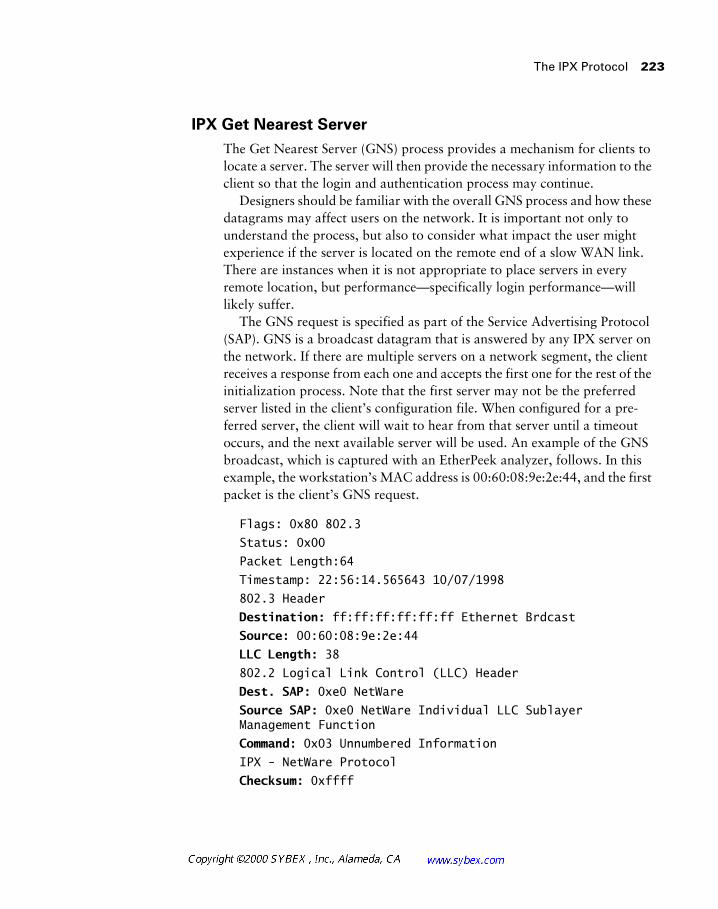
The IPX Protocol 223
IPX Get Nearest Server
The Get Nearest Server (GNS) process provides a mechanism for clients to locate a server. The server will then provide the necessary information to the client so that the login and authentication process may continue.
Designers should be familiar with the overall GNS process and how these datagrams may affect users on the network. It is important not only to understand the process, but also to consider what impact the user might experience if the server is located on the remote end of a slow WAN link. There are instances when it is not appropriate to place servers in every remote location, but performance—specifically login performance—will likely suffer.
The GNS request is specified as part of the Service Advertising Protocol (SAP). GNS is a broadcast datagram that is answered by any IPX server on the network. If there are multiple servers on a network segment, the client receives a response from each one and accepts the first one for the rest of the initialization process. Note that the first server may not be the preferred server listed in the client’s configuration file. When configured for a pre-ferred server, the client will wait to hear from that server until a timeout occurs, and the next available server will be used. An example of the GNS broadcast, which is captured with an EtherPeek analyzer, follows. In this example, the workstation’s MAC address is 00:60:08:9e:2e:44, and the first packet is the client’s GNS request.
Flags: 0x80 802.3
Status: 0x00
Packet Length:64
Timestamp: 22:56:14.565643 10/07/1998
802.3 Header
Destination: ff:ff:ff:ff:ff:ff Ethernet Brdcast
Source: 00:60:08:9e:2e:44
LLC Length: 38
802.2 Logical Link Control (LLC) Header
Dest. SAP: 0xe0 NetWare
Source SAP: 0xe0 NetWare Individual LLC Sublayer Management Function
Command: 0x03 Unnumbered Information
IPX - NetWare Protocol
Checksum: 0xffff
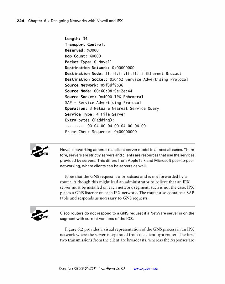
224 Chapter 6 � Designing Networks with Novell and IPX
Length: 34
Transport Control:
Reserved: %0000
Hop Count: %0000
Packet Type: 0 Novell
Destination Network: 0x00000000
Destination Node: ff:ff:ff:ff:ff:ff Ethernet Brdcast
Destination Socket: 0x0452 Service Advertising Protocol
Source Network: 0xf3df9b36
Source Node: 00:60:08:9e:2e:44
Source Socket: 0x4000 IPX Ephemeral
SAP - Service Advertising Protocol
Operation: 3 NetWare Nearest Service Query
Service Type: 4 File Server
Extra bytes (Padding):
......... 00 04 00 04 00 04 00 04 00
Frame Check Sequence: 0x00000000
Novell networking adheres to a client-server model in almost all cases. There-fore, servers are strictly servers and clients are resources that use the services provided by servers. This differs from AppleTalk and Microsoft peer-to-peer networking, where clients can be servers as well.
Note that the GNS request is a broadcast and is not forwarded by a router. Although this might lead an administrator to believe that an IPX server must be installed on each network segment, such is not the case. IPX places a GNS listener on each IPX network. The router also contains a SAP table and responds as necessary to GNS requests.
Cisco routers do not respond to a GNS request if a NetWare server is on the segment with current versions of the IOS.
Figure 6.2 provides a visual representation of the GNS process in an IPX network where the server is separated from the client by a router. The first two transmissions from the client are broadcasts, whereas the responses are
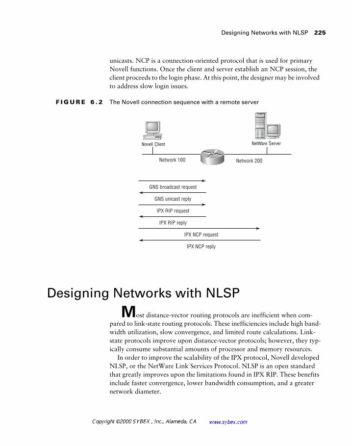
Designing Networks with NLSP 225
unicasts. NCP is a connection-oriented protocol that is used for primary Novell functions. Once the client and server establish an NCP session, the client proceeds to the login phase. At this point, the designer may be involved to address slow login issues.
F I G U R E 6 . 2 The Novell connection sequence with a remote server
Designing Networks with NLSP
Most distance-vector routing protocols are inefficient when com-pared to link-state routing protocols. These inefficiencies include high band-width utilization, slow convergence, and limited route calculations. Link-state protocols improve upon distance-vector protocols; however, they typ-ically consume substantial amounts of processor and memory resources.
In order to improve the scalability of the IPX protocol, Novell developed NLSP, or the NetWare Link Services Protocol. NLSP is an open standard that greatly improves upon the limitations found in IPX RIP. These benefits include faster convergence, lower bandwidth consumption, and a greater network diameter.
C S
226 Chapter 6 � Designing Networks with Novell and IPX
Networks that use both IPX RIP and NLSP are limited to the 15-hop diameter imposed by IPX RIP. It is possible to adjust the hop count during redistribu-tion; however, this can be confusing in a troubleshooting scenario and should only be used with clear documentation and training.
Unlike IPX EIGRP, NLSP is available on servers, which can permit its use on populated segments. This factor can facilitate migration to an all-NLSP network, which would allow for a greater network diameter.
In addition, NLSP supports route aggregation, a service not supported by IPX EIGRP or IPX RIP. This option can greatly reduce the size of the IPX routing table.
Network architects should limit the number of routing nodes per NLSP area when designing their networks. The recommended limit is approxi-mately 400 nodes; however, a more accurate impact definition may be found with the formula n*log(n).
NLSP is also best deployed with each area contained in a geographic region—a single campus, for example. Large, international IPX networks should not place all routers in a single area.
Incorporating NLSP into a network design is made easier by the auto-matic redistribution mechanism on Cisco routers. Routers running both IPX RIP and NLSP will automatically learn of the other process’s routes, and the implementation will automatically limit the likelihood of routing loops. Note that this may lead to suboptimal routing, and designers should verify the routing table following implementation to confirm that the paths selected are, in fact, the most desirable.
Some administrators are leery of deploying NLSP because they believe that readdressing will be required. Readdressing is necessary only to create logical areas for summarization. If the network resides in a single area, readdressing will not be required.
This leads to a design consideration for new networks, of course. Designers should strive to create logical addressing schemes even when not designing for NLSP, for two reasons. First, a logical addressing scheme will greatly assist in address assignments and troubleshooting. Second, the use of logical address-ing will avail route summarization options in the future should the network expand beyond the initially conceived boundaries.
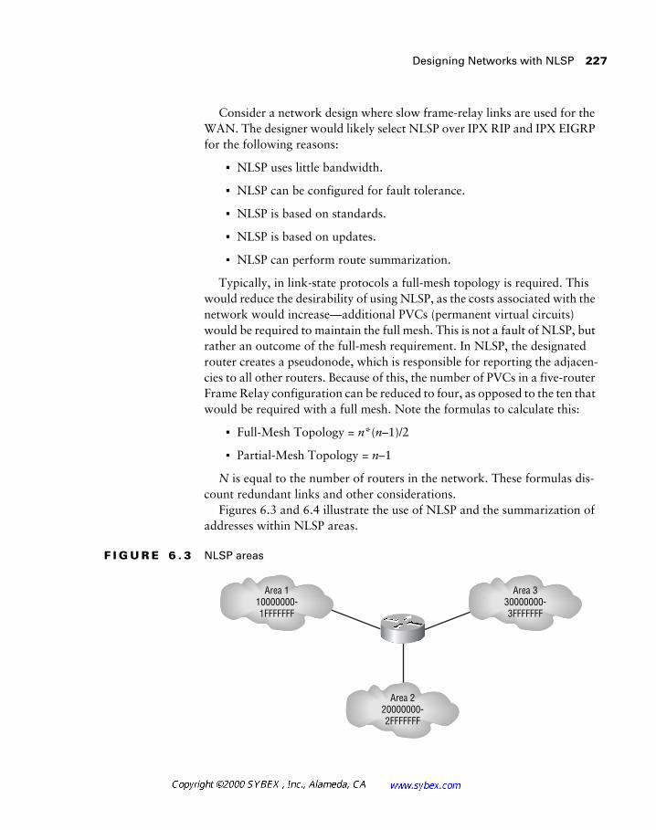
Designing Networks with NLSP 227
Consider a network design where slow frame-relay links are used for the WAN. The designer would likely select NLSP over IPX RIP and IPX EIGRP for the following reasons:
� NLSP uses little bandwidth.
� NLSP can be configured for fault tolerance.
� NLSP is based on standards.
� NLSP is based on updates.
� NLSP can perform route summarization.
Typically, in link-state protocols a full-mesh topology is required. This would reduce the desirability of using NLSP, as the costs associated with the network would increase—additional PVCs (permanent virtual circuits) would be required to maintain the full mesh. This is not a fault of NLSP, but rather an outcome of the full-mesh requirement. In NLSP, the designated router creates a pseudonode, which is responsible for reporting the adjacen-cies to all other routers. Because of this, the number of PVCs in a five-router Frame Relay configuration can be reduced to four, as opposed to the ten that would be required with a full mesh. Note the formulas to calculate this:
� Full-Mesh Topology = n*(n–1)/2
� Partial-Mesh Topology = n–1
N is equal to the number of routers in the network. These formulas dis-count redundant links and other considerations.
Figures 6.3 and 6.4 illustrate the use of NLSP and the summarization of addresses within NLSP areas.
F I G U R E 6 . 3 NLSP areas
Area 110000000-1FFFFFFF
Area 330000000-3FFFFFFF
Area 220000000-2FFFFFFF
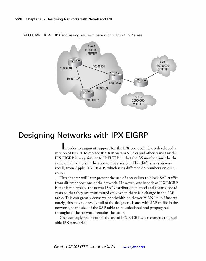
228 Chapter 6 � Designing Networks with Novell and IPX
F I G U R E 6 . 4 IPX addressing and summarization within NLSP areas
Designing Networks with IPX EIGRP
In order to augment support for the IPX protocol, Cisco developed a version of EIGRP to replace IPX RIP on WAN links and other transit media. IPX EIGRP is very similar to IP EIGRP in that the AS number must be the same on all routers in the autonomous system. This differs, as you may recall, from AppleTalk EIGRP, which uses different AS numbers on each router.
This chapter will later present the use of access lists to block SAP traffic from different portions of the network. However, one benefit of IPX EIGRP is that it can replace the normal SAP distribution method and control broad-casts so that they are transmitted only when there is a change in the SAP table. This can greatly conserve bandwidth on slower WAN links. Unfortu-nately, this may not resolve all of the designer’s issues with SAP traffic in the network, as the size of the SAP table to be calculated and propagated throughout the network remains the same.
Cisco strongly recommends the use of IPX EIGRP when constructing scal-able IPX networks.
Area 330000000-3FFFFFFF
Area 220000000-2FFFFFFF
Area 110000000-1FFFFFFF
10000101
10000102
10000103
10000003
10000002
10000001
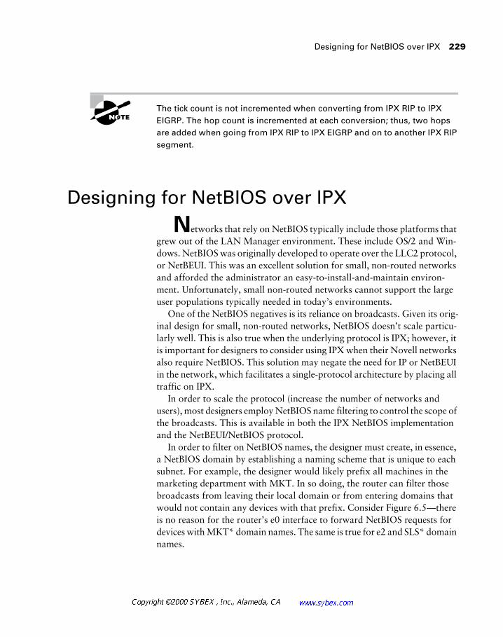
Designing for NetBIOS over IPX 229
The tick count is not incremented when converting from IPX RIP to IPX EIGRP. The hop count is incremented at each conversion; thus, two hops are added when going from IPX RIP to IPX EIGRP and on to another IPX RIP segment.
Designing for NetBIOS over IPX
Networks that rely on NetBIOS typically include those platforms that grew out of the LAN Manager environment. These include OS/2 and Win-dows. NetBIOS was originally developed to operate over the LLC2 protocol, or NetBEUI. This was an excellent solution for small, non-routed networks and afforded the administrator an easy-to-install-and-maintain environ-ment. Unfortunately, small non-routed networks cannot support the large user populations typically needed in today’s environments.
One of the NetBIOS negatives is its reliance on broadcasts. Given its orig-inal design for small, non-routed networks, NetBIOS doesn’t scale particu-larly well. This is also true when the underlying protocol is IPX; however, it is important for designers to consider using IPX when their Novell networks also require NetBIOS. This solution may negate the need for IP or NetBEUI in the network, which facilitates a single-protocol architecture by placing all traffic on IPX.
In order to scale the protocol (increase the number of networks and users), most designers employ NetBIOS name filtering to control the scope of the broadcasts. This is available in both the IPX NetBIOS implementation and the NetBEUI/NetBIOS protocol.
In order to filter on NetBIOS names, the designer must create, in essence, a NetBIOS domain by establishing a naming scheme that is unique to each subnet. For example, the designer would likely prefix all machines in the marketing department with MKT. In so doing, the router can filter those broadcasts from leaving their local domain or from entering domains that would not contain any devices with that prefix. Consider Figure 6.5—there is no reason for the router’s e0 interface to forward NetBIOS requests for devices with MKT* domain names. The same is true for e2 and SLS* domain names.
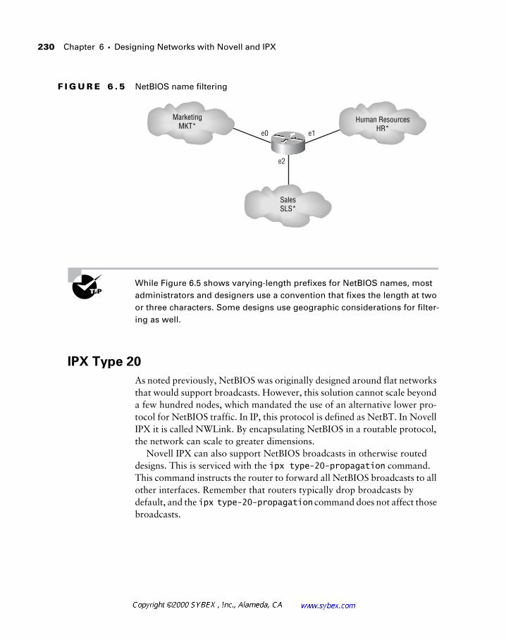
230 Chapter 6 � Designing Networks with Novell and IPX
F I G U R E 6 . 5 NetBIOS name filtering
While Figure 6.5 shows varying-length prefixes for NetBIOS names, most administrators and designers use a convention that fixes the length at two or three characters. Some designs use geographic considerations for filter-ing as well.
IPX Type 20
As noted previously, NetBIOS was originally designed around flat networks that would support broadcasts. However, this solution cannot scale beyond a few hundred nodes, which mandated the use of an alternative lower pro-tocol for NetBIOS traffic. In IP, this protocol is defined as NetBT. In Novell IPX it is called NWLink. By encapsulating NetBIOS in a routable protocol, the network can scale to greater dimensions.
Novell IPX can also support NetBIOS broadcasts in otherwise routed designs. This is serviced with the ipx type-20-propagation command. This command instructs the router to forward all NetBIOS broadcasts to all other interfaces. Remember that routers typically drop broadcasts by default, and the ipx type-20-propagation command does not affect those broadcasts.
MarketingMKT*
Human ResourcesHR*
SalesSLS*
e0 e1
e2
IP eXchange Gateway 231
The NetBIOS protocol is fundamental to Windows networking. It will be pre-sented in greater detail, as it relates to Windows, in Chapter 7. Please note that Windows 2000 and Active Directory promise to remove the dependency on NetBIOS from the Windows environment.
IPX Access Lists
Cisco routers support filtering based on a number of protocols, including IPX. In the Novell environment, the designer may choose to employ access lists for security or scalability reasons.
One of the most common reasons for deploying IPX access lists concerns the propagation of SAP traffic. These service advertisements can quickly impact overall network performance, especially on slower WAN links. Con-sider for a moment the SAP traffic generated by servers in Tokyo. While the data center in Sydney may need to receive these updates, it is unlikely that the Chicago office will need access to files and printers in the Tokyo office. By employing SAP filters, the designer can reduce the size of the Chicago office’s SAP table. Administrators should note that input filters will block SAPs from the local table, while output filters will block the transmission of the SAP entry—the local router will remain aware of the advertised service.
IP eXchange Gateway
The IP eXchange gateway product, now owned by Cisco, was designed to provide access to the Internet and other IP-based resources without installing an IP stack on every client workstation in the Novell environment.
Unfortunately, the simplified workstation administration was offset by the slower performance of gateway translation and the installation of client software for the IP eXchange product. In addition, a server running either Novell or Windows NT was required for the translation, which introduced a single point of failure and added administration.
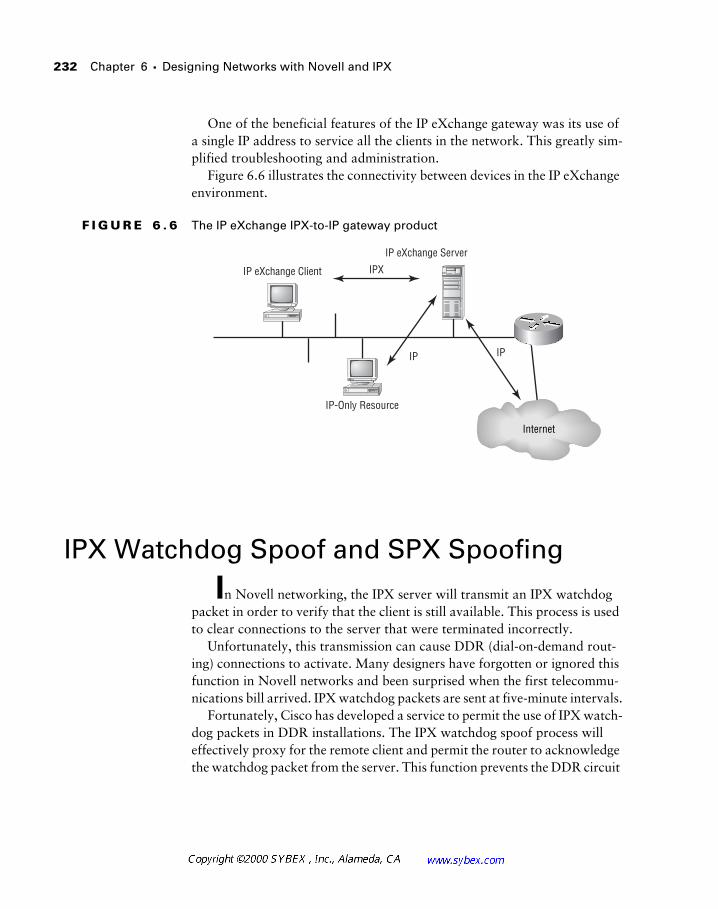
232 Chapter 6 � Designing Networks with Novell and IPX
One of the beneficial features of the IP eXchange gateway was its use of a single IP address to service all the clients in the network. This greatly sim-plified troubleshooting and administration.
Figure 6.6 illustrates the connectivity between devices in the IP eXchange environment.
F I G U R E 6 . 6 The IP eXchange IPX-to-IP gateway product
IPX Watchdog Spoof and SPX Spoofing
In Novell networking, the IPX server will transmit an IPX watchdog packet in order to verify that the client is still available. This process is used to clear connections to the server that were terminated incorrectly.
Unfortunately, this transmission can cause DDR (dial-on-demand rout-ing) connections to activate. Many designers have forgotten or ignored this function in Novell networks and been surprised when the first telecommu-nications bill arrived. IPX watchdog packets are sent at five-minute intervals.
Fortunately, Cisco has developed a service to permit the use of IPX watch-dog packets in DDR installations. The IPX watchdog spoof process will effectively proxy for the remote client and permit the router to acknowledge the watchdog packet from the server. This function prevents the DDR circuit
IP-Only Resource
IP eXchange Client
IP eXchange Server
IPX
IP IP
Internet
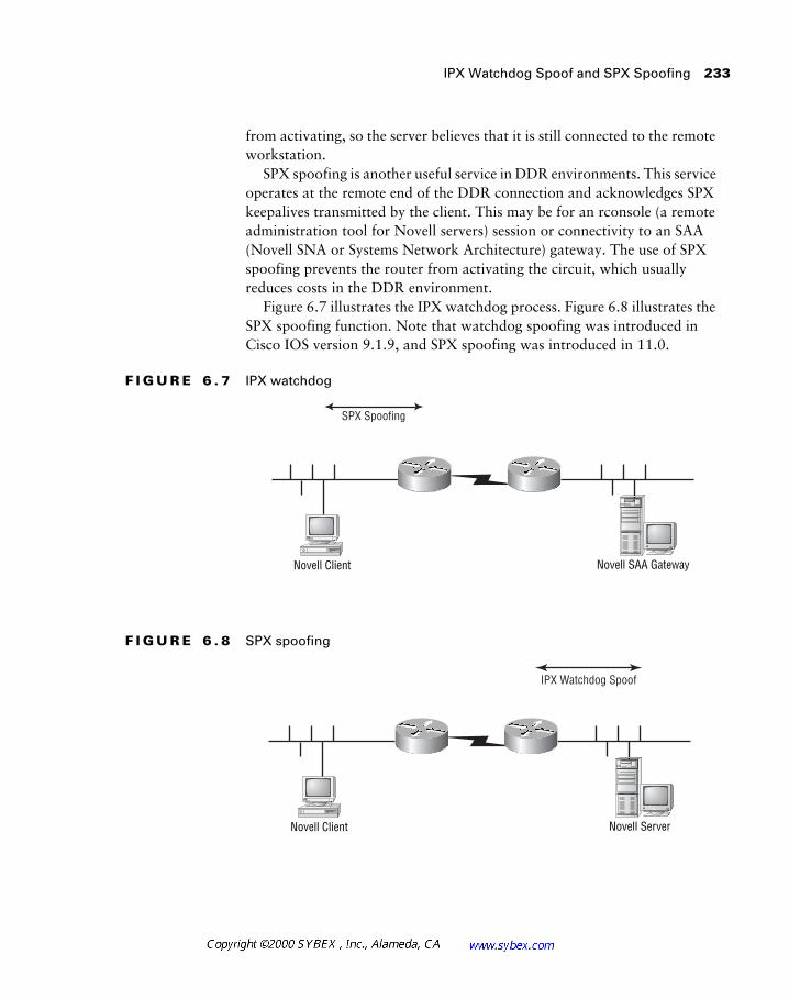
IPX Watchdog Spoof and SPX Spoofing 233
from activating, so the server believes that it is still connected to the remote workstation.
SPX spoofing is another useful service in DDR environments. This service operates at the remote end of the DDR connection and acknowledges SPX keepalives transmitted by the client. This may be for an rconsole (a remote administration tool for Novell servers) session or connectivity to an SAA (Novell SNA or Systems Network Architecture) gateway. The use of SPX spoofing prevents the router from activating the circuit, which usually reduces costs in the DDR environment.
Figure 6.7 illustrates the IPX watchdog process. Figure 6.8 illustrates the SPX spoofing function. Note that watchdog spoofing was introduced in Cisco IOS version 9.1.9, and SPX spoofing was introduced in 11.0.
F I G U R E 6 . 7 IPX watchdog
F I G U R E 6 . 8 SPX spoofing
SPX Spoofing
Novell SAA GatewayNovell Client
IPX Watchdog Spoof
Novell ServerNovell Client
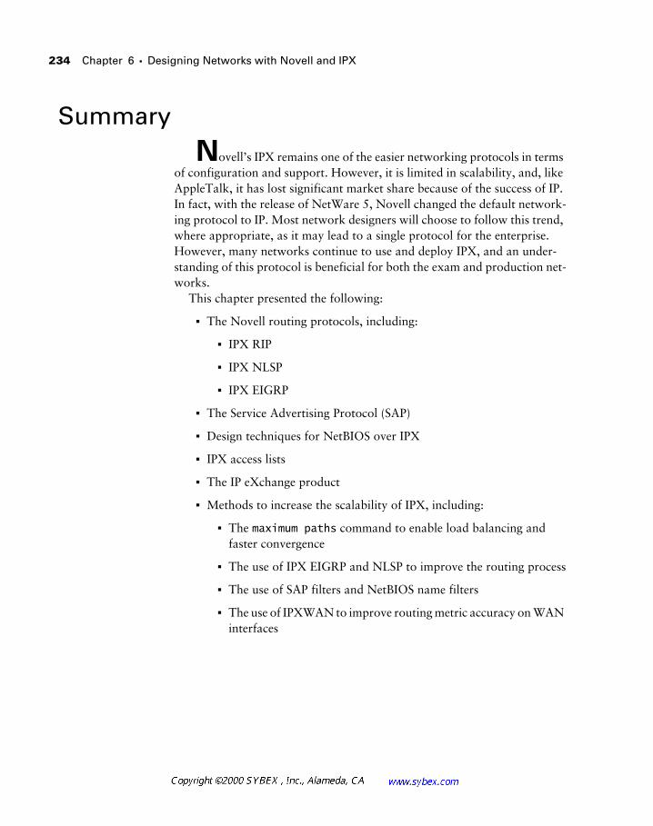
234 Chapter 6 � Designing Networks with Novell and IPX
Summary
Novell’s IPX remains one of the easier networking protocols in terms of configuration and support. However, it is limited in scalability, and, like AppleTalk, it has lost significant market share because of the success of IP. In fact, with the release of NetWare 5, Novell changed the default network-ing protocol to IP. Most network designers will choose to follow this trend, where appropriate, as it may lead to a single protocol for the enterprise. However, many networks continue to use and deploy IPX, and an under-standing of this protocol is beneficial for both the exam and production net-works.
This chapter presented the following:
� The Novell routing protocols, including:
� IPX RIP
� IPX NLSP
� IPX EIGRP
� The Service Advertising Protocol (SAP)
� Design techniques for NetBIOS over IPX
� IPX access lists
� The IP eXchange product
� Methods to increase the scalability of IPX, including:
� The maximum paths command to enable load balancing and faster convergence
� The use of IPX EIGRP and NLSP to improve the routing process
� The use of SAP filters and NetBIOS name filters
� The use of IPXWAN to improve routing metric accuracy on WAN interfaces
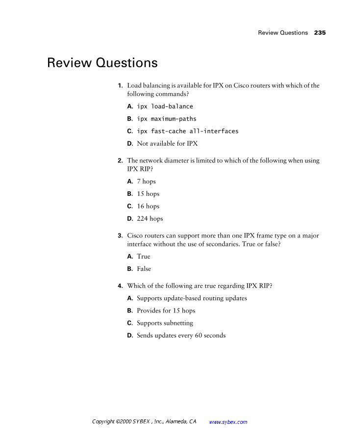
Review Questions 235
Review Questions
1. Load balancing is available for IPX on Cisco routers with which of the following commands?
A. ipx load-balance
B. ipx maximum-paths
C. ipx fast-cache all-interfaces
D. Not available for IPX
2. The network diameter is limited to which of the following when using IPX RIP?
A. 7 hops
B. 15 hops
C. 16 hops
D. 224 hops
3. Cisco routers can support more than one IPX frame type on a major interface without the use of secondaries. True or false?
A. True
B. False
4. Which of the following are true regarding IPX RIP?
A. Supports update-based routing updates
B. Provides for 15 hops
C. Supports subnetting
D. Sends updates every 60 seconds
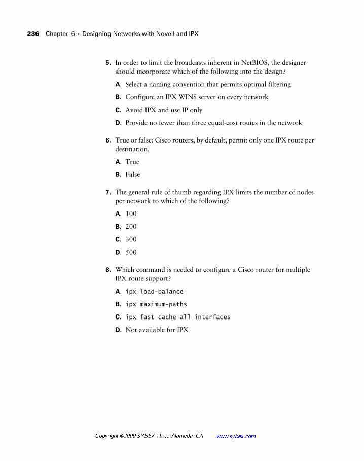
236 Chapter 6 � Designing Networks with Novell and IPX
5. In order to limit the broadcasts inherent in NetBIOS, the designer should incorporate which of the following into the design?
A. Select a naming convention that permits optimal filtering
B. Configure an IPX WINS server on every network
C. Avoid IPX and use IP only
D. Provide no fewer than three equal-cost routes in the network
6. True or false: Cisco routers, by default, permit only one IPX route per destination.
A. True
B. False
7. The general rule of thumb regarding IPX limits the number of nodes per network to which of the following?
A. 100
B. 200
C. 300
D. 500
8. Which command is needed to configure a Cisco router for multiple IPX route support?
A. ipx load-balance
B. ipx maximum-paths
C. ipx fast-cache all-interfaces
D. Not available for IPX
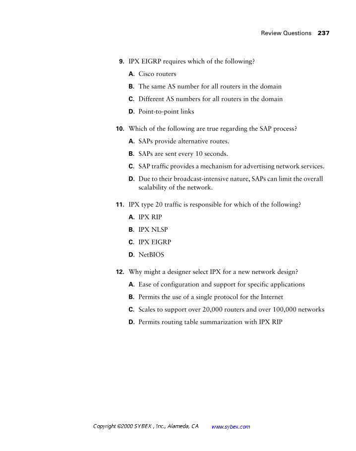
Review Questions 237
9. IPX EIGRP requires which of the following?
A. Cisco routers
B. The same AS number for all routers in the domain
C. Different AS numbers for all routers in the domain
D. Point-to-point links
10. Which of the following are true regarding the SAP process?
A. SAPs provide alternative routes.
B. SAPs are sent every 10 seconds.
C. SAP traffic provides a mechanism for advertising network services.
D. Due to their broadcast-intensive nature, SAPs can limit the overall scalability of the network.
11. IPX type 20 traffic is responsible for which of the following?
A. IPX RIP
B. IPX NLSP
C. IPX EIGRP
D. NetBIOS
12. Why might a designer select IPX for a new network design?
A. Ease of configuration and support for specific applications
B. Permits the use of a single protocol for the Internet
C. Scales to support over 20,000 routers and over 100,000 networks
D. Permits routing table summarization with IPX RIP
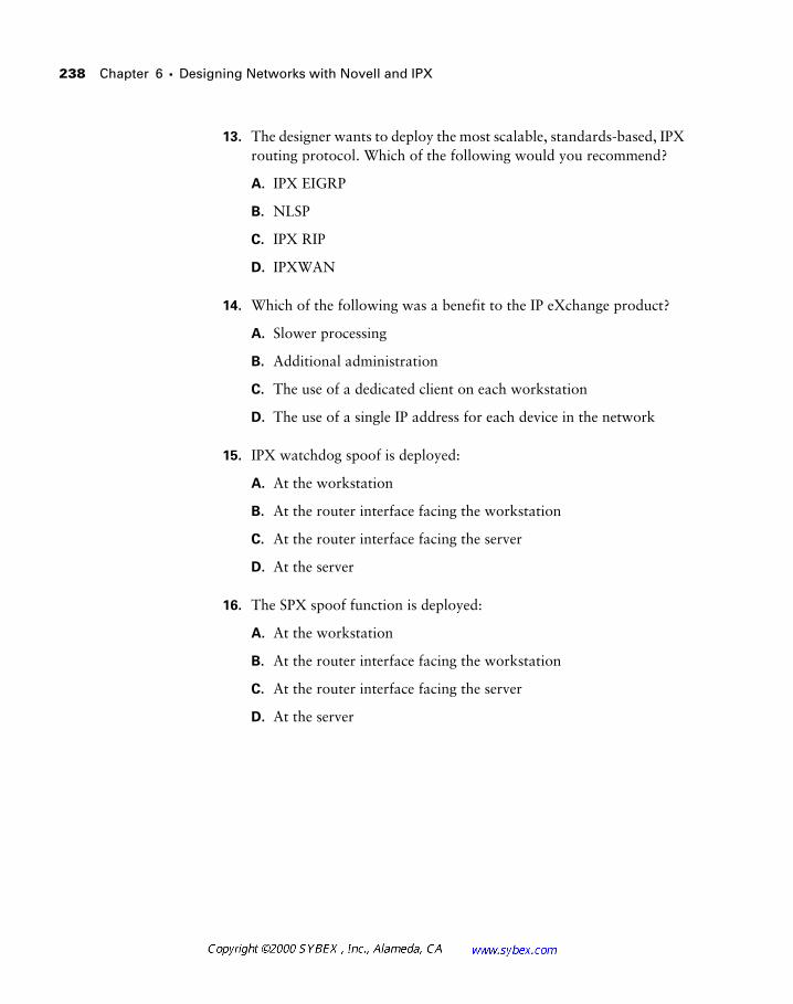
238 Chapter 6 � Designing Networks with Novell and IPX
13. The designer wants to deploy the most scalable, standards-based, IPX routing protocol. Which of the following would you recommend?
A. IPX EIGRP
B. NLSP
C. IPX RIP
D. IPXWAN
14. Which of the following was a benefit to the IP eXchange product?
A. Slower processing
B. Additional administration
C. The use of a dedicated client on each workstation
D. The use of a single IP address for each device in the network
15. IPX watchdog spoof is deployed:
A. At the workstation
B. At the router interface facing the workstation
C. At the router interface facing the server
D. At the server
16. The SPX spoof function is deployed:
A. At the workstation
B. At the router interface facing the workstation
C. At the router interface facing the server
D. At the server
Review Questions 239
17. Which of the following is not true regarding NLSP?
A. NLSP supports summarization.
B. NLSP is a link-state protocol.
C. NLSP is a distance-vector protocol.
D. NLSP is not a replacement for IPX RIP.
18. Why would a designer wish to use IPX watchdog spoofing and SPX spoofing?
A. To prevent activation of DDR circuits
B. To filter SAP broadcasts
C. To make sure DDR circuits do not disconnect
D. To encapsulate these packets across WAN links
19. The delay for GNS queries on a serverless segment is (assume version 11.2 of the IOS for this question)?
A. 500 ms
B. 1 second
C. 0 ms
D. Variable depending on the LAN media
20. The router may be configured to:
A. Respond to GNS queries in a round-robin fashion.
B. Respond to GNS queries when there is a server on the local segment.
C. Encapsulate GNS queries for transport to a central server.
D. The router does not respond to GNS queries. This is a server function.
240 Chapter 6 � Designing Networks with Novell and IPX
Answers to Review Questions
1. B.
2. B.
3. B.
The administrator must use subinterfaces or secondaries.
4. B, D.
5. A.
6. A.
7. D.
8. B.
9. A, B.
10. C, D.
11. D.
12. A.
13. B.
This is one of the few times when the Cisco solution isn’t the requested one. IPX EIGRP is not an open standard and requires the use of all Cisco routers.
14. D.
15. C.
16. B.
17. C.
18. A.
19. C.
20. A.
Chapter
7Designing for Windows Networking
CISCO INTERNETWORK DESIGN EXAM OBJECTIVES COVERED IN THIS CHAPTER:
� Examine a client’s requirements and construct an appropriate
NetBIOS design solution.
� Design a source-route-bridged internetwork that provides
connectivity for NetBIOS applications and controls NetBIOS
explorer traffic.
As the most popular desktop operating environment, Windows holds a substantial position of prominence in modern network designs. Yet this chapter truly encompasses a great deal more than just networking with Windows-based systems and the design criteria for these environments. It also incorporates information regarding the other major desktop pro-tocols—AppleTalk and IPX—as they relate to each other and as they com-pare to Windows-based systems.
This chapter also discusses the NetBIOS protocol, the foundation of the Windows-based operating systems. NetBIOS-based networks are found in the following operating systems/environments:
� Microsoft LAN Manager
� OS/2 LAN Manager
� MS-DOS with the LAN Manager Client
� Windows for Workgroups
� Windows 95/98
� Windows NT/2000
Also identified in this chapter is the importance of the interoperation of NetBIOS with other protocols. For example, NetBIOS, as a foundation for Windows-based networks, was originally designed to operate over NetBEUI, a non-routable protocol. Both IPX and TCP/IP have been enhanced to sup-port NetBIOS encapsulation, greatly enhancing the protocol’s incorporation into modern large-scale networks and providing designers with a means to support NetBIOS without NetBEUI.
Desktop Protocols 243
Desktop Protocols
As mentioned in previous chapters, all of the desktop protocols were designed around the client/server model (although Macintosh and Windows platforms could service both functions). This design includes the use of LANs with multiple hosts and typically operates as a single broadcast domain. The client is responsible for locating the server—the GNS process in IPX, for example—and the protocols rely on broadcasts, which adds sub-stantially to the network load.
Unlike NetBEUI, the original underlying protocol for NetBIOS, the other common desktop protocols use routable Layer 3 structures. In Novell net-works, these are NCP and SPX packets on top of IPX packets; in Macintosh environments, these are the protocols that comprise AppleTalk. As such, desktop protocols are defined at Layer 3 and above in reference to the OSI model. Most designers work with the desktop protocols as suites rather than addressing the facets of each individual protocol in the stack. This works from an architecture standpoint, as the protocols were designed to operate together, and most desktop issues may be isolated to the access layer of the hierarchical model.
Broadcasts
The issue of broadcasts in designs has been raised throughout this book. This is predominately due to the client workstation impact of broadcasts and the overhead on the individual processors caused by receipt of those datagrams. This is not an issue with unicasts, where the destination station performs all processing required by the upper-layer protocols. However, in broadcasts, all nodes in the broadcast domain must process the packet, and the majority of the nodes will discard the information, resulting in waste.
Broadcasts may be measured using two methods: broadcasts per second and broadcasts as a percentage. A good metric is dependent on the number of broadcasts per second—100 being a recommended guideline. Unfortunately, most networkers learned a long time ago that 10 percent broadcast traffic was a threshold and that networks were healthy so long as traffic remained
244 Chapter 7 � Designing for Windows Networking
below that value. Yet in practice, using a percentage as a metric is too limited for a number of reasons:
� As theoretical data rates increase, the percentage method permits an increase in the number of broadcasts.
� The percentage method does not consider the true impact of broad-casts in the network. For example, bandwidth is not a concern until collisions, contention, buffering, and other factors are surpassed—none of which relates to broadcasts directly.
� Broadcasts require the host processor to parse the datagram before the packet can be discarded. Since most broadcasts are not destined for a specific host, this is unnecessary overhead.
� The processing of broadcasts can quickly consume processing cycles on the host. At approximately 100 broadcasts per second, a Pentium 90 host is using up to two percent of its processor. While faster pro-cessors will also affect this figure, the load from broadcasts does not remain linear. There may be sufficient processor capacity available, but why make it do unnecessary work?
Windows Networks
The NetBIOS protocol is traditionally mapped to the session layer of the OSI model. It relies on names and name queries to locate resources within the network. Thus, network designers should keep the following in mind when architecting Windows-based networks:
� NetBIOS can operate over three lower-layer transports: NetBEUI, NWLink (NetBIOS over IPX), and NetBT (NetBIOS over TCP/IP; commonly referred to as NBT). NetBEUI is not routable.
� Most scalable NetBIOS designs require the use of filters. This man-dates a naming convention that lends itself to access lists.
� Cisco routers avail name caching and proxying as enhanced options in NetBIOS networks. Designers should consider these features.
Windows Networks 245
Workgroups and Domains
Groups of computers in Windows-based networks may be organized in one of two logical clusters: workgroups and domains. These groupings are not unlike the zone function in AppleTalk, but there are a few differences.
The basic grouping of machines is a workgroup. Workgroups may be cre-ated by any set of workstations, and the cluster does not participate in any authentication or central administration process. Each machine in a work-group may permit access to its resources, and any machine may join the workgroup. Thus the security level in workgroups is quite low, and the model is only suited to small organizations when administration is shared among all the users.
Domains, more formal groupings of computers than workgroups, signif-icantly change the level of security offered to the organization. First, domains are administered via a Primary Domain Controller (PDC). There can be only one PDC for the domain, and it is authoritative for that domain. To provide redundancy, the PDC may be supported by any number of Backup Domain Controllers (BDCs). In practice, most organizations deploy only one or two BDCs in their configurations, although it may be warranted to deploy more. BDCs are typically installed in remote locations to speed local login and authentication while retaining a centralized administrative model.
Windows Domains
The domain concept establishes the authentication and security administra-tion model for Windows-based networks. However, there are times when scalability or administrative concerns warrant the use of more than a single domain controller.
There are several domain models that are employed in modern Windows networks. They range from the relatively simple single domain, which is best suited to smaller organizations, to the multiple master domain model, which is typically used in large, multinational organizations.
Single domain A single domain model is best used for small to medium-sized environments with a single administrative scope.
Global domain The global domain model incorporates numerous domains that are administered by different organizations, typically within the same corporation. In this configuration, all domains trust all other domains.
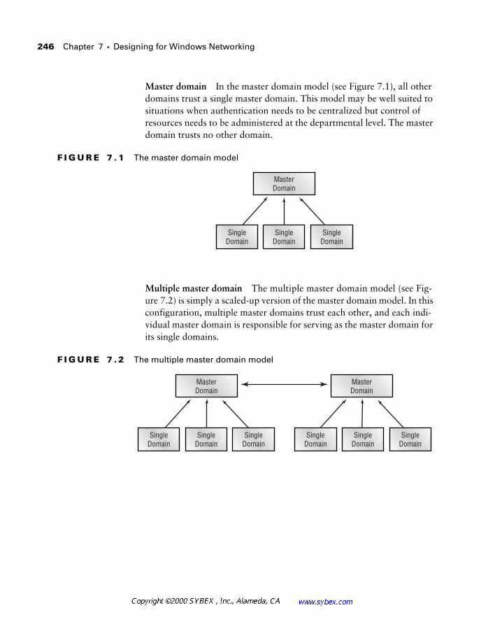
246 Chapter 7 � Designing for Windows Networking
Master domain In the master domain model (see Figure 7.1), all other domains trust a single master domain. This model may be well suited to situations when authentication needs to be centralized but control of resources needs to be administered at the departmental level. The master domain trusts no other domain.
F I G U R E 7 . 1 The master domain model
Multiple master domain The multiple master domain model (see Fig-ure 7.2) is simply a scaled-up version of the master domain model. In this configuration, multiple master domains trust each other, and each indi-vidual master domain is responsible for serving as the master domain for its single domains.
F I G U R E 7 . 2 The multiple master domain model
SingleDomain
SingleDomain
SingleDomain
MasterDomain
MasterDomain
SingleDomain
SingleDomain
SingleDomain
SingleDomain
SingleDomain
SingleDomain
MasterDomain
Windows Networks 247
Name Resolution Services
Computers are quite comfortable operating with numerical values of signif-icant length. Humans, on the other hand, typically appreciate text-based information and names. For example, we could certainly address everyone by a unique identification number—a Social Security number in the United States, for example. Thus, people would address me as 123-45-6789, and I would never turn around when someone said “Rob” at a party. Unfortu-nately, I have a difficult time remembering my own Social Security number, let alone those of my friends, family, and colleagues. (Of course, I sometimes forget names too, but I’d prefer not to dwell on that.)
In the computing environment, this idea holds true. I could certainly ask you to connect to the Web site at 10.62.70.133, but that would be harder to remember and would communicate no information regarding the content of the site. Yet if I were to say, “Connect to www.sybex.com,” you would have an immediate trigger for remembering the site name and likely would asso-ciate it with this book.
All that said, a name resolution service provides users with a simple mech-anism for names to associate with computer-related identification—typically an address operating at Layer 3 of the OSI model. As detailed in the next sec-tions, the common name resolution services in Windows networking—LMHOSTS, WINS, and DNS—are each unique, though they provide similar functions.
LMHOSTS
The first generation of name resolution services for NetBIOS involved the LMHOSTS file. This file was manually maintained and static, and it resolved host names in the LAN Manager (LM) environment. The file could be main-tained on each host and typically listed only a few critical resources, includ-ing off-subnet domain controllers.
The LMHOSTS file could also reside on the Primary Domain Controller. In this configuration, the clients would query the PDC for information. Unfortunately, this configuration required a great deal of manual effort, and maintenance of the file was only possible for small networks. Therefore, this configuration is not recommended as a modern solution.
248 Chapter 7 � Designing for Windows Networking
WINS
Designers need to remember that Windows-based networking was originally designed for small, single-network environments. This meant that broad-casts were an acceptable method for registering and locating services. How-ever, in modern routed networks, broadcasts are not permitted to cross Layer 3 boundaries. In addition, addressing of IP resources migrated from static assignments to dynamic ones, which simplified administration at the host and worked to prevent the waste of IP v4 addresses.
It became fairly clear that the LMHOSTS file would not scale to support significant networks. Each machine was tasked with maintaining its own file, and administrators either frequently scheduled downloads to keep the information on each workstation current or they had to maintain an LMHOSTS file on the PDC that was referenced by each workstation in the network.
To provide a dynamic method for registering NetBIOS names and asso-ciating them with IP addresses, Microsoft developed the Windows Internet Name Service (WINS). The service provides the following benefits:
� Clients on different subnets can register with a central repository for name resolution.
� Dynamic host address assignment (DHCP, or Dynamic Host Con-figuration Protocol) can be used while preserving name resolution services.
� Broadcasts can be reduced significantly.
� NetBIOS names can be mapped to IP addresses.
Though WINS allows for broadcasts to be reduced significantly, by default the clients will still broadcast name information for compatibility with older systems. Broadcasts should be disabled whenever possible. While beyond the scope of this book, interested readers should consult Microsoft’s docu-mentation regarding B-nodes, P-nodes, and H-nodes.
Windows Networks 249
The WINS mechanism requires that the workstation know the address of the WINS server. This may be manually configured on the client, but it is typ-ically provided in concert with DHCP. With the specific IP address of the WINS server, the client may communicate using unicast packets.
DHCP is described in greater detail later in this chapter.
The WINS server may also be accessed via a subnet broadcast mechanism, and designers may wish to consider using the WINS Relay function to for-ward WINS datagrams. This installation effectively proxies the WINS server onto the local subnet but, due to the extra administration and cost factors, is seldom used. Recall that proxies add additional overhead and latency
Finally, there may be multiple WINS servers on the network for redun-dancy and scalability. These servers interconnect via a replication process. Under this configuration, the client is configured (locally or via DHCP) with multiple WINS server addresses. Upon bootup, the client registers with a WINS server; if a server in the list is unavailable, the client attempts a con-nection with another in the list. This configuration is particularly common in international networks, as the latency and cost of sending name information across the WAN is quite high (albeit quickly becoming cheaper). However, performance for the end user is substantially greater with a local name res-olution resource.
In a campus configuration, WINS servers may be deployed at the distri-bution layer in order to provide redundancy. The challenge for most design-ers is to limit the number of servers—and like most other things, simpler is better. Two or three WINS servers should not prove to be a significant problem regarding replication overhead and administration. However, some early deployments opted for a WINS server per domain or per department. Such a design quickly falls into the “bad thing” category.
DNS and Dynamic DNS
The Domain Name Service (DNS) was originally developed to provide name resolution for Unix hosts and their IP addresses. It was fundamentally easier to telnet to Cygnus, a server, than it was to telnet to 192.168.67.219. In BIND, or the DNS daemon process in Unix, administrators manually and
250 Chapter 7 � Designing for Windows Networking
statically entered name and IP address information. The static nature of DNS is also its most significant negative, as the administrator must manually establish and maintain each entry. This precludes the use of DNS in DHCP environments, where the address is assigned dynamically.
A fairly new enhancement to DNS has emerged within the past year—Dynamic DNS (DDNS). The DDNS specification is compatible with tradi-tional DNS, but information regarding addresses and host names is learned dynamically. This makes DNS compatible with DHCP, which is a significant enhancement in the address assignment arena.
In Windows NT, it is also possible to configure the interchange of WINS information into the DNS structure. This permits non-Windows-based systems—Unix hosts, primarily—to use name references. Most large net-work designs create a sub-domain for names learned via this method. Thus, an existing Unix DNS structure is maintained for company.com, for example, while a sub-domain of wins.company.com is referenced for the dynamic entries. In addition, Windows clients may use DNS information for name resolution.
A number of third-party programs are available to integrate WINS, DHCP, and DNS/DDNS functions. Yet as the enterprise grows, many administrators find that the integrated applications are not powerful enough. Some applications worth considering include NetID and Meta IP from Nortel and Checkpoint, respectively.
DHCP
The Dynamic Host Configuration Protocol (DHCP) is actually an open standard that is used by Unix and Macintosh clients as well as Windows-based systems. However, the protocol attained mainstream, corporate recognition when the server module was incorporated into Windows NT.
DHCP 251
DHCP allows a host to learn its IP address dynamically. This process is termed a lease, as the address assigned belongs to the host for an adminis-tratively defined time. By default, on Windows implementations this assign-ment is for 72 hours.
DHCP leases are discussed in the following section.
From a router perspective, DHCP requires one of two components—a DHCP server on the local subnet or a method for forwarding the broadcast across the router. DHCP requests are broadcasts, so the designer needs a DHCP server presence on each segment in the network. This clearly would not scale well and is impractical in most network designs; however, this would provide addressing information to the clients.
The alternative is to provide a little help to DHCP. This is accomplished with the IP helper address, a statically defined address on each router inter-face that is connected to the local segment requiring the help, which in turn points to the DHCP server. Broadcast requests for addresses are sent to the helper address as unicasts or directed broadcasts, significantly reducing overall broadcast traffic. Most DHCP implementations, including Microsoft’s, can provide a great deal of information to the client as well, including time servers, default gateways, and other address-based services.
When designing for DHCP, most architects and administrators consider the following:
� DHCP lease length
� DHCP server redundancy
� Address assignments
Cisco routers can provide limited DHCP services; however, most installations make use of a dedicated server.
252 Chapter 7 � Designing for Windows Networking
DHCP Lease Length
The length of the DHCP lease governs the amount of time a host “owns” the address. In order for the host to continue using the address, it must renew with the server before the lease expires. Designers must consider the over-head of this renewal traffic and the impact of failed or unavailable DHCP servers. In general, fixed configurations are appropriate venues for long leases, and short leases are applicable in more dynamic installations.
Consider a fully functioning network with a hundred workstations and a lease length of five minutes. This is an extreme example (DHCP typically sends a renewal request at an interval equal to one-half of the lease timer), but the overhead incurred would be 6000 requests per hour for just IP addresses. This is a high amount of overhead for information that should not change under normal circumstances. In addition, when a lease expires, the host must release its IP address. Without a DHCP server, it would be unable to communicate on the network for want of an address.
The alternative to a short lease is to make the lease very long. Consider the impact of a lease equal to 60 days. Should the hosts remain on a local subnet with very few changes, this would substantially reduce the volume of traffic. However, this would not be appropriate for a hotelling installation. Hotelling is a concept introduced years ago where notebook users would check into a cubicle for a day or even a week. DHCP is a great solution for such an instal-lation as the MAC addresses are constantly changing, but a long lease time would be inappropriate here. Consider a scenario where each visitor con-nects once per quarter, or every 90 days. And, for this example, presume that there are 800 users of the service, and the pool is a standard Class C network of 254 host addresses. If the lease were long—90 days for this example—only the first 250 users would be able to obtain an address. Clearly, this is not appropriate to the type of installation—an important consideration for the designer.
As mentioned earlier, the default DHCP lease renewal interval is 72 hours. This results in renewal requests every 36 hours (typically, this process begins at 50 percent of the lease period). For reference, the mechanism by which DHCP obtains an address is illustrated in Figure 7.3. Note that DHCP uses a system of discovery to locate the DHCP server—a phase that makes use of the helper function. Once the DHCP server is found, the offer is returned to the workstation, and the request is acknowledged or declined.
254 Chapter 7 � Designing for Windows Networking
DHCP Server Redundancy
Given the critical function of the DHCP server, most designers place at least two of them in a network, thus providing DHCP server redundancy. This design offers benefits similar to the redundant WINS servers discussed pre-viously in this chapter. Depending on the implementation, these DHCP servers may or may not be able to share address assignment information. Multiple helper addresses may be placed on each interface on a Cisco router.
Many designers break the DHCP scope when working with DHCP ser-vers that are not capable of automatic redundancy. Recall from the discussion on IP addressing that designers frequently reserve a small number of addresses at the beginning of the address range for routers, switches, and other network equipment. In a single DHCP server installation, the scope would expand from this initial address reservation, whereas dual DHCP servers would take this scope and divide it to provide two ranges of addresses for the same subnet. For example, Table 7.1 documents a single DHCP server scope definition, where the server does not support redundancy.
All of the addresses in Table 7.1 are naturally subnetted.
In a redundant DHCP installation, many administrators will configure their servers as shown in the example in Table 7.2.
T A B L E 7 . 1 An Example of a Non-Redundant, Single DHCP Server
Scope Function Address Range
Administration 192.168.1.1 to 192.168.1.31
Users 192.168.1.32 to 192.168.1.254
DHCP 255
The configuration shown in Table 7.2 would support 95 users under the worst-case single failure. Given this information, designers should consider the network mask in use, the number of users per subnet, expansion, VLSM, and other factors before selecting a DHCP redundancy method.
As presented earlier in this chapter, modifications to the lease renewal interval can be used to reduce the impact of a DHCP server failure.
Older DHCP clients required access to the DHCP server on each boot before they could use the address previously assigned, even if the lease interval was still valid. This behavior has been changed in newer releases of the client soft-ware, and the workstation can use the assigned address up to the end of the lease.
Address Assignments
Certain network devices do not lend themselves to dynamic address assign-ment. Routers, switches, managed hubs, servers, and printers all fall into this category. Many networks opt to define an address block for these devices at the beginning or end of the subnet. For example, possibly all host addresses from .1 to .31 are omitted from the DHCP scope for manual assignment. This assumes that no network mask on populated segments uses less than /24 (255.255.255.0), which is a consideration when compos-ing a number scheme.
T A B L E 7 . 2 An Example of Redundant, Non-Aware DHCP Servers
Scope Function Address Range
Administration 192.168.1.1 to 192.168.1.31
Users, Server A 192.168.1.32 to 192.168.1.127
Users, Server B 192.168.1.128 to 192.168.1.254
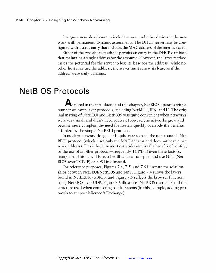
256 Chapter 7 � Designing for Windows Networking
Designers may also choose to include servers and other devices in the net-work with permanent, dynamic assignments. The DHCP server may be con-figured with a static entry that includes the MAC address of the interface card.
Either of the two above methods permits an entry in the DHCP database that maintains a single address for the resource. However, the latter method raises the potential for the server to lose its lease for the address. While no other host may use the address, the server must renew its lease as if the address were truly dynamic.
NetBIOS Protocols
As noted in the introduction of this chapter, NetBIOS operates with a number of lower-layer protocols, including NetBEUI, IPX, and IP. The orig-inal mating of NetBEUI and NetBIOS was quite convenient when networks were very small and didn’t need routers. However, as networks grew and became more complex, the need for routers quickly overrode the benefits afforded by the simple NetBEUI protocol.
In modern network designs, it is quite rare to need the non-routable Net-BEUI protocol (which uses only the MAC address and does not have a net-work address). This is because most networks require the benefits of routing or the use of another protocol—frequently TCP/IP. Given these factors, many installations will forego NetBEUI as a transport and use NBT (Net-BIOS over TCP/IP) or NWLink instead.
For reference purposes, Figures 7.4, 7.5, and 7.6 illustrate the relation-ships between NetBEUI/NetBIOS and NBT. Figure 7.4 shows the layers found in NetBEUI/NetBIOS, and Figure 7.5 reflects the browser function using NetBIOS over UDP. Figure 7.6 illustrates NetBIOS over TCP and the structure used when connecting to file systems (in this example, adding pro-tocols to support Microsoft Exchange).
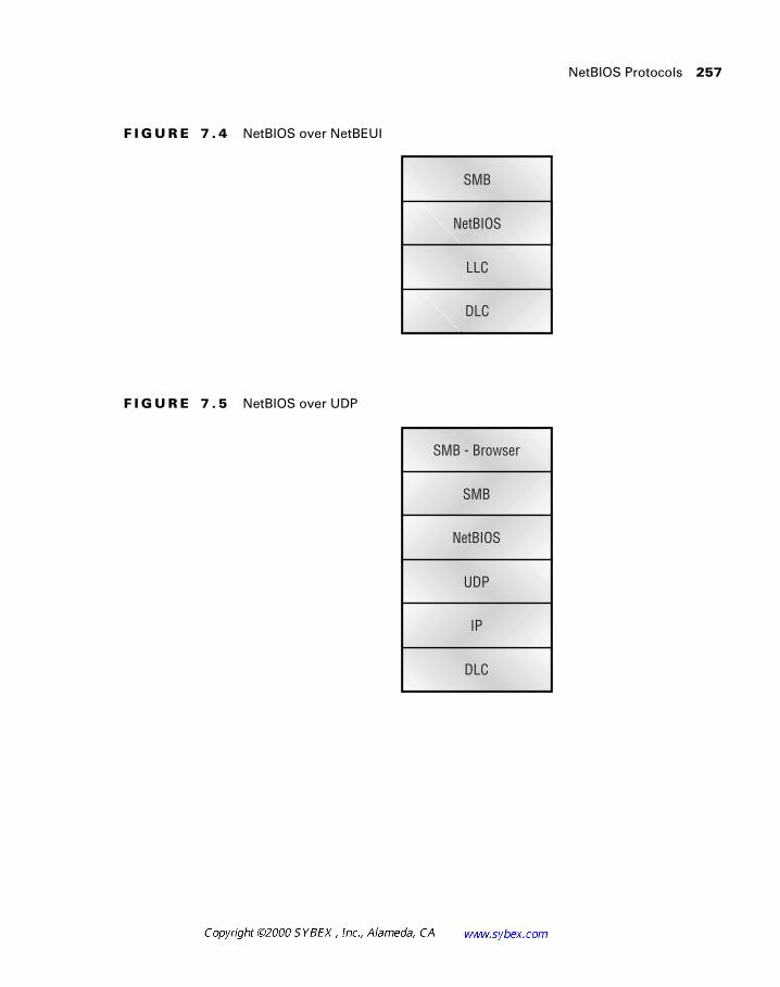
NetBIOS Protocols 257
F I G U R E 7 . 4 NetBIOS over NetBEUI
F I G U R E 7 . 5 NetBIOS over UDP
SMB
NetBIOS
LLC
DLC
SMB - Browser
SMB
NetBIOS
UDP
DLC
IP
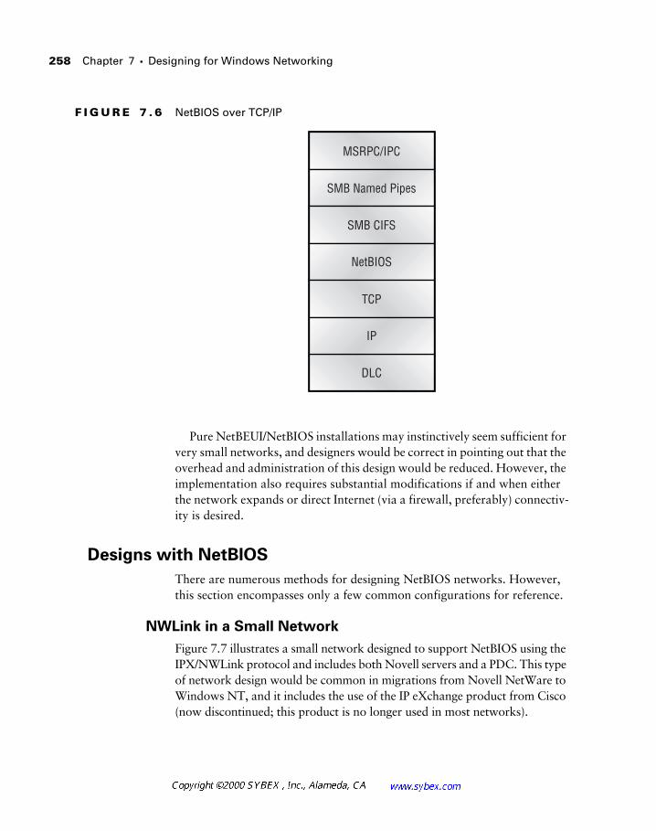
258 Chapter 7 � Designing for Windows Networking
F I G U R E 7 . 6 NetBIOS over TCP/IP
Pure NetBEUI/NetBIOS installations may instinctively seem sufficient for very small networks, and designers would be correct in pointing out that the overhead and administration of this design would be reduced. However, the implementation also requires substantial modifications if and when either the network expands or direct Internet (via a firewall, preferably) connectiv-ity is desired.
Designs with NetBIOS
There are numerous methods for designing NetBIOS networks. However, this section encompasses only a few common configurations for reference.
NWLink in a Small Network
Figure 7.7 illustrates a small network designed to support NetBIOS using the IPX/NWLink protocol and includes both Novell servers and a PDC. This type of network design would be common in migrations from Novell NetWare to Windows NT, and it includes the use of the IP eXchange product from Cisco (now discontinued; this product is no longer used in most networks).
MSRPC/IPC
SMB Named Pipes
SMB CIFS
NetBIOS
TCP
DLC
IP
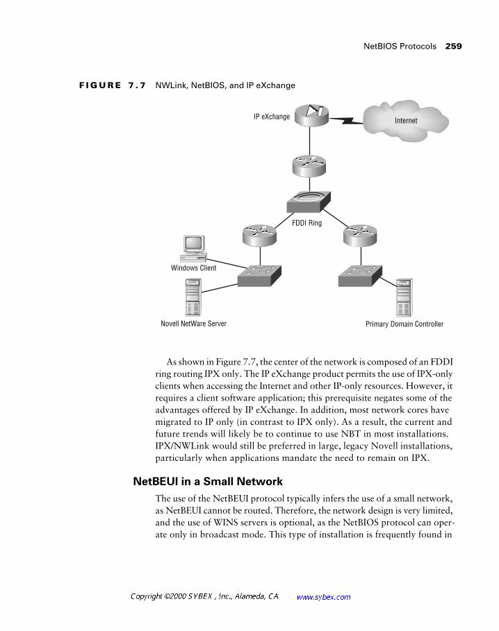
NetBIOS Protocols 259
F I G U R E 7 . 7 NWLink, NetBIOS, and IP eXchange
As shown in Figure 7.7, the center of the network is composed of an FDDI ring routing IPX only. The IP eXchange product permits the use of IPX-only clients when accessing the Internet and other IP-only resources. However, it requires a client software application; this prerequisite negates some of the advantages offered by IP eXchange. In addition, most network cores have migrated to IP only (in contrast to IPX only). As a result, the current and future trends will likely be to continue to use NBT in most installations. IPX/NWLink would still be preferred in large, legacy Novell installations, particularly when applications mandate the need to remain on IPX.
NetBEUI in a Small Network
The use of the NetBEUI protocol typically infers the use of a small network, as NetBEUI cannot be routed. Therefore, the network design is very limited, and the use of WINS servers is optional, as the NetBIOS protocol can oper-ate only in broadcast mode. This type of installation is frequently found in
Windows Client
Novell NetWare Server
IP eXchange
Primary Domain Controller
FDDI Ring
Internet
260 Chapter 7 � Designing for Windows Networking
schools and small offices, although basic home networks also may use only NetBEUI/NetBIOS.
In these networks, a single station is elected the Browse Master. All other stations advertise their presence on the network with a broadcast and use a broadcast to locate resources. The election of the Browse Master is also han-dled via broadcasts, and the network can support several backup Browse Masters. Remember that this type of network was deployed frequently in peer-to-peer environments, not in client/server installations (for which the broadcast model works well).
NBT in a Large Network
The IP protocol exploded onto the Windows networking scene with the growth of the Internet. However, the protocol offers benefits beyond access to the world’s largest network.
The IP protocol is one of the most scalable. New features are being added to the protocol every month, and should the designer wish, it is possible to use IP with up to 1000 hosts on a subnet. However, this design requires spe-cific attention to broadcasts and bandwidth.
Network designers frequently select the IP protocol for Windows instal-lations in modern network design. The obvious benefit is standardization on a single protocol that is supported on all desktop platforms. With NBT, the circle is complete, and Windows-based systems can also operate.
Many of the other topics in this chapter relate to NBT, including WINS and DHCP. Figure 7.8 illustrates one possible example of an NBT network installation for a multinational firm. Note that most firms would include BDC installations and multiple WINS servers.
Designers should note that the SAMBA utility is available for Unix hosts to provide SMB (Server Message Block) services to Windows-based systems. This permits file and print sharing (functions that use the SMB protocol) with-out the need for the NFS and LPD Unix applications on Windows.
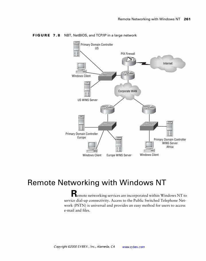
Remote Networking with Windows NT 261
F I G U R E 7 . 8 NBT, NetBIOS, and TCP/IP in a large network
Remote Networking with Windows NT
Remote networking services are incorporated within Windows NT to service dial-up connectivity. Access to the Public Switched Telephone Net-work (PSTN) is universal and provides an easy method for users to access e-mail and files.
PIX Firewall
Windows Client
Windows Client
Windows ClientEurope WINS Server
Primary Domain ControllerWINS Server
Africa
Primary Domain ControllerEurope
Primary Domain ControllerUS
US WINS Server
Internet
Corporate WAN
262 Chapter 7 � Designing for Windows Networking
Microsoft’s Windows NT Remote Access Server (RAS) is built upon the Point-to-Point Protocol (PPP), which provides support for multiple upper-layer protocols, including those identified in Table 7.3.
Cisco products will also support these encapsulations when running IOS ver-sion 11.1 or greater.
Summary
This chapter addressed a number of issues related to the common desktop protocols—NetBIOS, AppleTalk, and IPX—and introduced net-working with Windows, the most common desktop environment.
T A B L E 7 . 3 PPP-Supported Protocols and Their RAS Names
Upper-Layer Protocol RAS Notation
TCP/IP IPCP
IPX IPXCP
NetBEUI NBFCP
Network Design in the Real World: Remote Access
From an administrative perspective, designers should discourage the use of a single server for RAS and traditional file and print functions. While Microsoft scaled RAS to 256 connections on the Alpha platform, it may be even better to consider a dedicated, hardware-based remote access solu-tion, such as the Cisco AS5x00 product line. Security, manageability, and scalability should drive this decision process, yet many RAS installations begin with cost and rapid deployment as driving factors.
Summary 263
Windows networking incorporates a number of standards and proprietary-based services, including WINS, DHCP, DNS, DDNS, NBT, NWLink, and domains, which are important for the designer to understand and consider when architecting the network.
This chapter discussed the following topics:
� The negatives of broadcasts in network designs
� The differences between workgroups and domains
� The use of the LMHOSTS file in NetBIOS networks
� The use of WINS servers in a network and their ability to reduce broadcast traffic in support of NetBIOS systems
� The integration of DNS and DDNS with WINS and NetBIOS networks
� The use of DHCP for address assignment
� The control of DHCP scopes to allocate permanent, manually assigned addresses to servers and routers
� Considerations for selecting a routable protocol for NetBIOS encapsulation
� The functionality of the Browse Master
� The RAS application and the underlying protocol support
In most modern networks, designers need to focus on the Windows envi-ronment more than Novell and AppleTalk. However, understanding the mechanisms by which each of the desktop protocols operates will greatly facilitate troubleshooting and support considerations. In addition, designers are frequently called upon to support multiple platform installations or to migrate from AppleTalk and IPX to IP.
While not addressed in this chapter, cost and history also are factors in NetBIOS/Windows network design. The battles between Novell and Microsoft have been effectively rendered moot, and the best outcome from this history is a realization that the best tool for the job makes the most sense.
The issue of thin Windows clients (terminals that display only applica-tions served from a multiuser server) is also outside the scope of this chapter.
264 Chapter 7 � Designing for Windows Networking
In short, much progress has been made in the technology of these tools in recent years. Designers should carefully measure the traffic loads generated by these devices, particularly during traditional peak traffic periods. Thin cli-ents can greatly simplify administrative issues, but it is important to ensure that sufficient capacity to store all data on the server is available, and that all mouse/keyboard and video updates are transmitted efficiently across the net-work—such datagrams consume a surprising amount of bandwidth.
Review Questions 265
Review Questions
1. Designers planning to use WINS must:
A. Plan to install a WINS server on every subnet
B. Manually enter all IP and NetBIOS name information
C. Also configure a DHCP server
D. Consider the need for multiple WINS servers
2. The LMHOSTS process:
A. Is suited to small networks only
B. Is recommended for large networks only
C. Requires the use of DHCP
D. Dynamically learns PDC and BDC information
3. NetBIOS over IPX is called:
A. NBT
B. NetBEUI
C. NWLink
D. NetBIOS does not operate over IPX
4. Broadcasts:
A. Are fine so long as they consume less than ten percent of bandwidth
B. Are unnecessary with desktop protocols
C. Should be reduced whenever possible to reduce unnecessary processing and conserve bandwidth
D. Should be regarded the same as unicasts
266 Chapter 7 � Designing for Windows Networking
5. Which of the following protocols may not be routed?
A. NetBEUI
B. IPX
C. IP
D. NWLink
6. The IP eXchange product provides designers of Windows-based networks:
A. The ability to configure the PDC on NetWare servers
B. The ability to configure up to three BDCs to run on three different NetWare servers
C. The ability to provide IP connectivity without loading IP on each client
D. IPX HRSP
7. Microsoft’s RAS product:
A. Provides DHCP services
B. Uses the PPP protocol
C. Supports IP only
D. Cannot run on an NT server
8. Traditionally, DNS was unable:
A. To dynamically interoperate with DHCP
B. To translate names to IP addresses
C. To operate in Unix environments
D. To accept manual mappings
Review Questions 267
9. A designer needs to create a network with 2000 Windows work-stations and servers while providing access to the Internet and Unix servers. The best solution would include:
A. IP eXchange and NWLink
B. NBT and IPX
C. NBT, WINS, DHCP, and TCP/IP
D. NetBEUI and Cisco GSR routers
10. Broadcasts are controlled:
A. With switches
B. With routers
C. With hubs
D. With repeaters
11. Designers attempt to reduce broadcasts for which of the following reasons?
A. Broadcasts require unnecessary processing by the workstations.
B. Broadcasts consume four times the bandwidth of data.
C. Broadcasts are not necessary in LAN protocols.
D. Broadcasts cannot operate in NBMA topologies.
12. In order to reduce bandwidth requirements on the WAN link, the designer might:
A. Place the DHCP server at the remote site and keep the lease timers short
B. Place the DHCP server at the remote site and lengthen the lease timers
C. Centralize the DHCP server and use the default DHCP timers
D. Use multiple DHCP servers with short timers
268 Chapter 7 � Designing for Windows Networking
13. A network contains 27 subnets. How many DHCP servers are required for dynamic address assignment?
A. One
B. Two—one configured as a BDC
C. 27
D. Cannot answer from the information provided
14. How do hosts locate the WINS server?
A. Using a multicast to 224.0.0.17
B. Using a unicast to an administratively defined address
C. Using the IP helper service
D. Using the DHCP server as a relay
15. Which of the following is true?
A. Cisco routers may function as WINS servers.
B. Cisco routers may function as DHCP servers.
C. Cisco routers may function as both WINS and DHCP servers.
D. None of the above.
16. NetBIOS networks should be designed:
A. Using only network masks of /24 (255.255.255.0)
B. With naming conventions that reflect the owner of the workstation
C. With numerical naming only
D. With naming conventions that begin with an easily filtered prefix

Review Questions 269
17. Which of the following limitations exist in DHCP?
A. DHCP cannot exist in WINS networks.
B. DHCP can assign addresses only to Windows-based machines.
C. Only one DHCP server can exist in the network.
D. None of the above.
18. Servers should always have the same IP address for administrative purposes. Therefore:
A. The DHCP scope should include a reservation block of addresses in the subnet for servers or should not include the address range.
B. DHCP cannot be used in the subnet.
C. Servers must all use the address 0.0.0.0 for all datagrams.
D. WINS must be used.
19. The master domain:
A. Trusts all single domains
B. Is trusted by all single domains in the group
C. Shares a bi-directional trust with all single domains
D. Can be the only domain in the corporation
20. The LAN services browser mechanism is replaced by:
A. DHCP
B. DDNS
C. WINS
D. LMHOSTS

270 Chapter 7 � Designing for Windows Networking
Answers to Review Questions
1. D.
2. A.
3. C.
4. C.
5. A.
6. C.
7. B.
8. A.
9. C.
10. B.
11. A.
12. B.
13. A.
14. B.
15. B.
16. D.
17. D.
18. A.
19. B.
20. C.
Chapter
8Designing for the WAN
CISCO INTERNETWORK DESIGN EXAM OBJECTIVES COVERED IN THIS CHAPTER:
� List common concerns that customers have about WAN
designs.
� Examine statements made by a customer and distinguish
issues that affect the choice of WAN designs.
� Design core WAN connectivity to maximize availability and
optimize utilization of resources.
� Design a full- or partial-mesh Frame Relay nonbroadcast
multiaccess (NBMA) core for full or partial connectivity.
� Choose a scalable topology for NBMA Frame Relay.
� Use subinterface Frame Relay configurations to design robust
core WANs.
Network designers frequently need to connect geographically distant locations with relatively high-speed links. Unfortunately, costs gen-erally increase as the available bandwidth increases, and thus the designer is compelled to find the best solution in terms of cost, performance, scalability, and availability.
There are a number of ways to connect networks across large geograph-ical areas. In the earliest networks, this required the use of expensive leased lines or slow dial-up connections—both of which were limited in terms of bandwidth compared to modern, cheaper solutions. Today’s offerings, which are substantially cheaper on a per-megabyte basis, include Frame Relay, ATM (Asynchronous Transfer Mode), and SMDS (Switched Multi-megabit Data Service). Each of these technologies relies on the reliability of modern fiber-optic and copper networks and scales to support at least DS-3 (45Mbps) bandwidth—ATM is currently available in OC-48 and OC-192 (optical carrier) offerings, yielding up to 10Gbps of bandwidth.
This chapter does not focus so much on the increasing performance of modern WAN technologies, such as DWDM (dense wavelength division multiplexing), which multiplies the number of signals that can traverse a fiber, or the issues surrounding OC-192 and OC-48 networks. Rather, each of these technologies (Frame Relay, ATM, and SMDS) is presented in detail, and the differences between frame-based and cell-based transports are dis-cussed. Additionally, this chapter focuses on the general concepts of wide area networking technologies. Beyond nontechnical concerns such as cost, this chapter reviews more technological factors, including scalability, reli-ability, and latency.
While SMDS is included in the CID exam objectives, its availability has waned in recent years. Standard ATM services have effectively replaced such instal-lations, while Frame Relay has always held a substantial market share. SMDS did not fail due to technology—in fact, it was a very good protocol. Rather, it required additional expertise and expensive equipment compared to the alternatives. Many providers never offered the technology.
Wide Area Network Technologies 273
Wide Area Network Technologies
The design goals—and technologies—of a wide area network (WAN) are slightly different than those for local area network (LAN) installations. For example, it is fairly simple to add an extra connection in a LAN, while in a WAN this may take 90 days or more. Also, in a LAN, most designers are concerned with port density and broadcast control, while in a WAN, band-width and cost are frequently the foremost concern. Further, the interactions with outside vendors required in a WAN can alter significantly the issues involved in the design.
There are two categories of WAN design technology in use today: dedi-cated services and switched services. Dedicated services include the tradi-tional leased T1 and T3 services. They are called dedicated services because only one connectionpoint, which follows a pre-determined path, exists within the circuit. This connection may be transported over shared media within the provider’s network; however, the full amount of bandwidth will always be allocated (dedicated) for the specific connection.
Readers may notice a lack of emphasis on dedicated services in this chapter. This is primarily due to the text’s focus on the Cisco exam objectives and the actual test. However, it is also presumed that most CCDP candidates are famil-iar with the basic concepts of these connections from their experience or the CCDA, CCNA, and CCNP materials. If the concepts of time division multiplexing, inverse multiplexing, and the serial protocols (HDLC, PPP) are unfamiliar, please make sure that you review this material before continuing your certi-fication efforts. While the test does not ask questions outside the constraints of the objectives, it presumes a certain foundation.
Switched services include circuit, packet, and cell-switched connections; ISDN, telephone service (POTS), X.25, Frame Relay, ATM, and SMDS. Switched services typically incorporate charges for distance and bandwidth used, but this is dependent on the specific tariff in use. Most telecommuni-cations services are charged based on a tariff— a set, regulated price struc-ture that includes parameters for installation and administration processes.
There are two benefits of switched technologies. First, in the case of dynamic circuits, the designer can establish a connection to any other eligible recipient. For example, both POTS and ISDN connections can be established with a simple access number—the connection into the network is sufficient,
274 Chapter 8 � Designing for the WAN
and there is no requirement to define each possible link ahead of time. Sec-ond, switched services typically share bandwidth better within the cloud. As this chapter’s discussion turns to committed information rates (CIR—Frame Relay) and SCR (Sustained Cell Rate—ATM), you will see that the network can logically adapt to the requirements of the users and allow bursts of traffic within the constraints of total capacity.
When reviewing the WAN technologies and designs presented in this chapter, it is important to consider the following issues: reliability, latency, cost, and traffic flows and traffic types. Most network designers focus ulti-mately on cost as the most important design consideration; however, reli-ability may require additional expense. Latency, various traffic flows, and traffic types are supported with most modern technologies and thus lose some importance in modern designs. Of course, this text ignores some of the older and more limited protocols in WAN design, such as BiSYNC and dig-ital data system (DDS) circuits—two areas in which these issues deserve more prominence.
Reliability
Unlike LAN connections, WAN links tend to be a bit unstable and often are unreliable. This may be due to fiber cuts, equipment failure, or misconfigura-tion by the service provider. Unfortunately, it is difficult to add reliability to
Network Design in the Real World: SONET
Private SONET rings (Synchronous Optical Networks), wireless, and certain point-to-point technologies are outside the scope of Cisco’s exam objec-tives. However, these solutions are frequently selected for an array of rea-sons, including facilities, security, and cost. The most scalable installations, at the lowest cost, frequently use Frame Relay and, to an increasing degree, ATM. Wireless technologies are well suited to temporary installations and areas where wire-based services are unavailable, although this alternative has gained favor as a means to reduce dependency on the carriers. SONET offers high reliability and is a fundamental transport technology in the car-rier world. Packet over SONET (PoS) and Dynamic Packet Transport (DPT) can both operate over these rings.
Wide Area Network Technologies 275
WAN installations simply by selecting a different technology. For example, Frame Relay is just as susceptible to a fiber cut as ATM; in fact, ATM trans-ports most Frame-Relay installations in the provider’s core network.
Since reliability is a physical-layer concern, augmented by the higher lay-ers, designers typically have to think of the physical layer first. For example, fiber cuts can be circumvented by wireless technologies, yet these are some-times degraded by snow, rain, or fog. To augment reliability from a physical context, the designer needs to consider the available options, many of which are beyond the scope of this text. (Consult with your vendors for the most current information regarding WAN options.)
However, it is possible to add a degree of reliability to the network with the selection of a WAN technology. This chapter addresses some forms of redundancy for network designers to consider. Frame Relay and ATM, with their ability to service multiple connections from a single port, typically pro-vide more reliability than point-to-point connections—should one virtual link fail, the other should still be available (presuming the lack of a port or local loop failure).
Latency
Latency, the delay introduced by network equipment, has become a minor concern in most designs as protocols have migrated toward delay tolerance in the data arena. However, with voice and video integration on data net-works, even today’s wire-speed offerings may require the attention once afforded time-sensitive protocols on slower links; this would include SNAP (Sub-Network Access Protocol), used in mainframe connectivity. Modern network designs can address these issues with queuing, low-latency hard-ware, cell-based technologies like ATM, and prioritization. One of the ben-efits afforded by ATM is a consistent latency within the network.
The latency category frequently incorporates throughput and delay fac-tors. Compared to LANs, most wide area links are very slow, and perfor-mance suffers as a result. Designers should work with application developers and server administrators to tune the network to address this limitation. Pos-sible solutions include compression and prioritization (queuing), yet these functions can degrade performance more than the link if not deployed cor-rectly. Designers should also make use of static routes or quiet routing pro-tocols and employ other techniques, such as IPX watchdog spoofing
276 Chapter 8 � Designing for the WAN
(discussed in Chapter 6), to control overhead traffic. Under the best circum-stances, designers should focus on moving limited amounts of data between servers on very slow WAN links whenever possible.
Cost
WAN networking costs typically exceed those for a LAN. There are a num-ber of reasons for this; the most significant factor is the recurring costs that exist in WAN networks. Unlike the LAN, where the company owns the con-nections between routers, the WAN infrastructure is owned by the tele-communications provider. As a result, the provider leases its fiber or copper cables. This differs from LAN installations, where the company purchases and installs its own cable. The initial cost of establishing a WAN may be greater, but the lack of recurring costs quickly reduces the amortized impact.
The technologies used to reduce WAN costs—Frame Relay, ATM, and SDMS—are presented throughout this chapter. Yet in short, Frame Relay
Network Design in the Real World: WAN Technologies and Latency
Historically, WAN access was provided by telecommunications service pro-viders on circuits originally provisioned for voice services. The system of T1 and E1 channels was mapped directly to the number of voice channel time slots afforded (24 for T1, 30 for E1). The technologies presented in this chap-ter are based upon these solutions.
Recently, however, advances in laser technology and the availability of fiber optics has provided designers with new solutions, including the option to use GigabitEthernet in some wide area solutions. While limited to approx-imately 55 miles, this connectivity works well in a metropolitan installation. Microwave and wireless laser solutions are also available to designers who wish to reduce the cost and installation time of traditional remote access.
In the context of latency, all of these options provide a more consistent transport infrastructure. Rather than converting from Ethernet to Frame Relay and back to Ethernet, the designer can install fairly long connections and maintain Ethernet throughout. This lack of conversion can substantially reduce the complexity of the installation and the latency.
Wide Area Network Technologies 277
provides the greatest savings per megabit. ATM is quickly providing savings in WAN costs, but this is based more on the integration of voice and data than on lower tariffs.
Though not discussed in this book, both MAN-based Ethernet and DSL, a shorter-range technology, appear to further reduce WAN costs.
Point-to-point circuits generally represent the highest cost in the WAN. This is because, unlike Frame Relay, the bandwidth is dedicated, which can oversubscribe and group users based on actual usage. Oversubscribing is the intentional configuration of more theoretical bandwidth on a circuit than it could accommodate. This is similar to providing 10 phones for 100 people—if, on average, only seven concurrent phone calls occur, there is sufficient capacity, even though the system is oversubscribed overall. The risk of 20 callers is very real, but the savings of not providing 100 lines is substantial.
Traffic Flows and Traffic Types
Compared to local area networks, some WANs provide limited protocol support. This may be for simplification, but in most cases this results from the desire to conserve the bandwidth that typically is needed to support additional protocols. The designer can consider encapsulation and other methodologies, including conversion and isolation, to remove or omit pro-tocols from the WAN. Many designers are converting from AppleTalk and IPX to IP.
Previous chapters have addressed the concept of tunneling in the context of AppleTalk and other protocols. However, the general concepts and con-cerns regarding tunnels are universal. The most significant issue with tunnels is performance, though troubleshooting is also a major issue that can be complicated by encapsulation.
Like other networking technologies, serial connections require a protocol to transmit information from one side of a link to another. The selection of an encapsulation, in addition to the use of tunnels and the type of traffic tra-versing the link, can impact performance and manageability. The encapsu-lations for data over serial lines are:
� SDLC
� Cisco’s HDLC
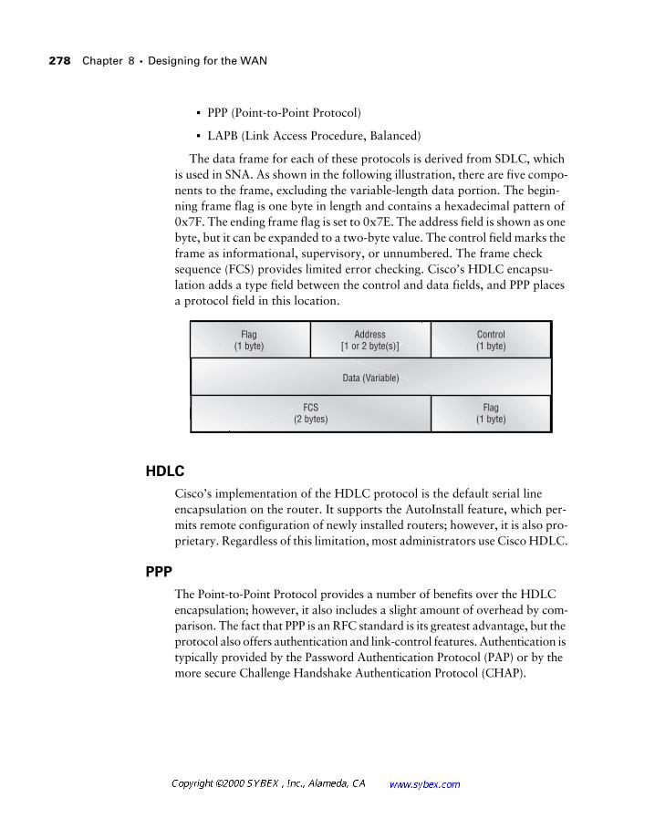
278 Chapter 8 � Designing for the WAN
� PPP (Point-to-Point Protocol)
� LAPB (Link Access Procedure, Balanced)
The data frame for each of these protocols is derived from SDLC, which is used in SNA. As shown in the following illustration, there are five compo-nents to the frame, excluding the variable-length data portion. The begin-ning frame flag is one byte in length and contains a hexadecimal pattern of 0x7F. The ending frame flag is set to 0x7E. The address field is shown as one byte, but it can be expanded to a two-byte value. The control field marks the frame as informational, supervisory, or unnumbered. The frame check sequence (FCS) provides limited error checking. Cisco’s HDLC encapsu-lation adds a type field between the control and data fields, and PPP places a protocol field in this location.
HDLC
Cisco’s implementation of the HDLC protocol is the default serial line encapsulation on the router. It supports the AutoInstall feature, which per-mits remote configuration of newly installed routers; however, it is also pro-prietary. Regardless of this limitation, most administrators use Cisco HDLC.
PPP
The Point-to-Point Protocol provides a number of benefits over the HDLC encapsulation; however, it also includes a slight amount of overhead by com-parison. The fact that PPP is an RFC standard is its greatest advantage, but the protocol also offers authentication and link-control features. Authentication is typically provided by the Password Authentication Protocol (PAP) or by the more secure Challenge Handshake Authentication Protocol (CHAP).
Data (Variable)
Flag(1 byte)
Control(1 byte)
Address[1 or 2 byte(s)]
Flag(1 byte)
FCS(2 bytes)
Network Design with Frame Relay 279
LAPB
Link Access Procedure, Balanced is a reliable encapsulation for serial con-nections. It provides the data-link layer for X.25, but it may be used without that protocol. LAPB features link compression and excellent error correc-tion, which makes it well suited to unreliable analog media. Because of this overhead, LAPB tends to be slower than other encapsulations.
One of the configuration options in LAPB is modulo, or the sequence number. Initial implementations of LAPB supported only eight sequence numbers—modulo 8, which quickly resulted in a windowing delay for higher speed connections. (Modulo 128 was developed to address this limi-tation.) Designers should make certain that the same value is used on both sides of the link.
Network Design with Frame Relay
Frame Relay networks offer the network designer many benefits that do not exist in point-to-point, leased-line transports. These include:
� Distance-insensitive billing
� Multiple destinations per physical interface
� The ability for data to burst above the tariffed data rate
Most vendors offer Frame Relay under a fairly simple tariff, or cost struc-ture, based on the reserved capacity of the virtual circuit. Leased lines charge on a per-mile basis, and the bandwidth charge is equal to the total capacity of the circuit. As a result, Frame Relay connections can be significantly less expensive, especially when traversing hundreds of miles.
Circuit costs are recurring and thus can quickly overshadow any installation and capital expenditures.
Frame Relay is also considered a burstable technology. This refers to the difference between reserved bandwidth and total potential bandwidth avail-able. Consider a point-to-point circuit—the network will transport only as much data as the circuit will provide, and unused bandwidth will remain
280 Chapter 8 � Designing for the WAN
unused because the connection is dedicated. Frame Relay circuits are typi-cally provisioned with a bandwidth reservation lower than the capacity of the link—256Kbps on a T1, for example. Vendors combine virtual circuits so that the remaining bandwidth is utilized, but if the physical media has unused bandwidth, any of the virtual circuits can burst beyond their alloca-tion and temporarily increase their available bandwidth.
Frame Relay circuits are typically provisioned with two distinct band-width parameters, unlike standard HDLC or switched-56 circuits, which are provisioned with the data rate equal to the port speed. In addition to the physical capacity of the circuit, Frame Relay incorporates a committed infor-mation rate, or CIR.
The CIR function varies with different telecommunications vendors, though most use the value to represent a guaranteed available bandwidth to the customer. This may be calculated on a per-second or per-minute basis, but the net result is that customers can reserve bandwidth at a lower level than the capacity of the local loop connection. For example, a CIR of 768Kbps on a T1 would offer at least 768Kbps to the customer and provide a burst up to 1.5Mbps for a short duration.
Different vendors implement bursting differently, including the concept of zero CIR, where no bandwidth is reserved. Designers should fully understand their vendor’s implementation before provisioning circuits.
Frame Relay connections use permanent virtual circuits (PVCs) to specify connections from one node to another. These PVCs are identified by a DLCI, or data link connection identifier. Frame Relay switches forward frames based solely on the DLCI in the header of each frame.
Switched virtual circuits (SVCs) are available in Frame Relay, yet most ven-dors do not support this configuration. As a result, this chapter discusses PVC-based Frame Relay connections only. PVCs and SVCs are discussed in more detail later in this chapter.
The Frame Relay switch simply takes one port/DLCI connection and for-wards it to another port/DLCI connection. In this context, the term “port” refers to the physical interface, and “DLCI” refers to the logical Frame Relay interface. DLCIs only have local significance, and while vendors typically
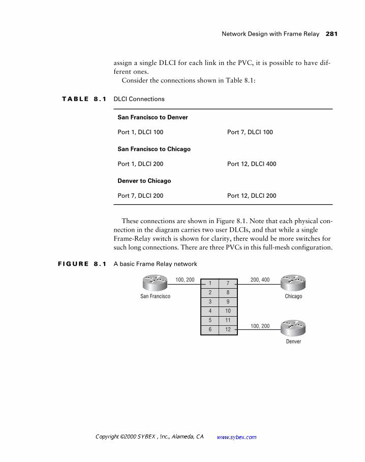
Network Design with Frame Relay 281
assign a single DLCI for each link in the PVC, it is possible to have dif-ferent ones.
Consider the connections shown in Table 8.1:
These connections are shown in Figure 8.1. Note that each physical con-nection in the diagram carries two user DLCIs, and that while a single Frame-Relay switch is shown for clarity, there would be more switches for such long connections. There are three PVCs in this full-mesh configuration.
F I G U R E 8 . 1 A basic Frame Relay network
T A B L E 8 . 1 DLCI Connections
San Francisco to Denver
Port 1, DLCI 100 Port 7, DLCI 100
San Francisco to Chicago
Port 1, DLCI 200 Port 12, DLCI 400
Denver to Chicago
Port 7, DLCI 200 Port 12, DLCI 200
ChicagoSan Francisco
Denver
1
2
3
4
5
6
7
8
9
10
11
12
100, 200 200, 400
100, 200
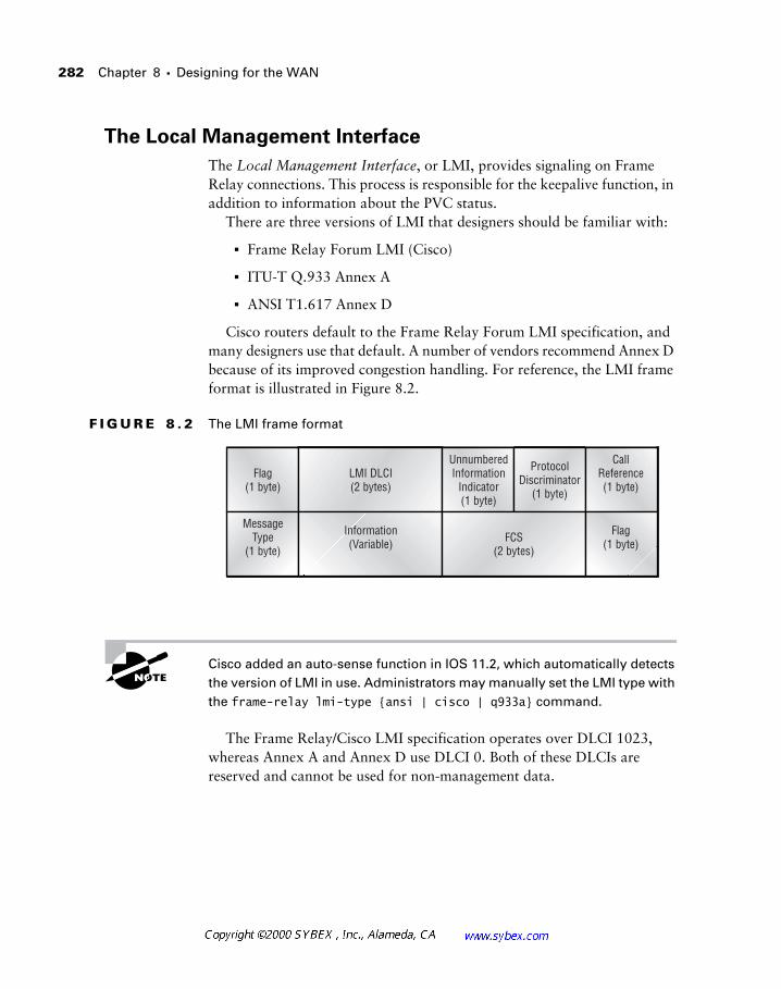
282 Chapter 8 � Designing for the WAN
The Local Management Interface
The Local Management Interface, or LMI, provides signaling on Frame Relay connections. This process is responsible for the keepalive function, in addition to information about the PVC status.
There are three versions of LMI that designers should be familiar with:
� Frame Relay Forum LMI (Cisco)
� ITU-T Q.933 Annex A
� ANSI T1.617 Annex D
Cisco routers default to the Frame Relay Forum LMI specification, and many designers use that default. A number of vendors recommend Annex D because of its improved congestion handling. For reference, the LMI frame format is illustrated in Figure 8.2.
F I G U R E 8 . 2 The LMI frame format
Cisco added an auto-sense function in IOS 11.2, which automatically detects the version of LMI in use. Administrators may manually set the LMI type with the frame-relay lmi-type {ansi | cisco | q933a} command.
The Frame Relay/Cisco LMI specification operates over DLCI 1023, whereas Annex A and Annex D use DLCI 0. Both of these DLCIs are reserved and cannot be used for non-management data.
UnnumberedInformation
Indicator(1 byte)
ProtocolDiscriminator
(1 byte)
CallReference(1 byte)
LMI DLCI(2 bytes)
Flag(1 byte)
Flag(1 byte)FCS
(2 bytes)
Information(Variable)
MessageType
(1 byte)
Network Design with Frame Relay 283
The Frame Relay Standard—RFC 1490
The use of standards-based protocols and technology is recommended whenever vendor operability is a concern. Standards-based systems also tend to garner better diagnostic support, including documentation.
Frame Relay is described in RFC 1490, which documents its support for both bridged and routed traffic. The RFC also documents the Inverse ARP function. Inverse ARP provides a mechanism for dynamically mapping upper-layer protocols to the appropriate lower-layer address. This function is enabled by default and can greatly simplify router configuration.
Frame Relay Address Mapping
As with other Layer 3 protocols, Frame Relay requires a mechanism for asso-ciating the network address with the data link address. This appears in the form of an address mapping.
Many network designers manually enter the mapping statements into the router, which can facilitate troubleshooting. The commands, which are entered on an interface level, note the protocol, the remote address, the DLCI, and, in these examples, the broadcast keyword.
frame-relay map ipx 200.0000.30a0.831d 200 broadcast
frame-relay map ip 10.11.200.2 200 broadcast
Note that each Layer 3 protocol is mapped separately to a DLCI.
Nonbroadcast Multiaccess
One of the more advanced concepts in WAN design involves the concept of nonbroadcast multiaccess (NBMA) technologies. Unlike LAN protocols, WAN installations were originally designed around simple point-to-point connections. Addressing was unnecessary, and in the most basic installa-tions, a connection required only one device to be DTE and the other DCE. Such connections are often used to link to routers together without the ben-efit of a DSU/CSU (data service unit/channel service unit).
Nonbroadcast multiaccess networks acknowledge the limitations of most WANs in comparison to local area networks. The typical wide area network does not lend itself well to broadcasts. This reflects the nonbroadcast portion of NBMA. The multiaccess portion acknowledges that some WAN technol-ogies provide more than one destination—recall that the first WAN links were simple point-to-point configurations.
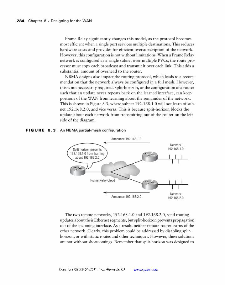
284 Chapter 8 � Designing for the WAN
Frame Relay significantly changes this model, as the protocol becomes most efficient when a single port services multiple destinations. This reduces hardware costs and provides for efficient oversubscription of the network. However, this configuration is not without limitations. When a Frame Relay network is configured as a single subnet over multiple PVCs, the route pro-cessor must copy each broadcast and transmit it over each link. This adds a substantial amount of overhead to the router.
NBMA designs also impact the routing protocol, which leads to a recom-mendation that the network always be configured in a full mesh. However, this is not necessarily required. Split-horizon, or the configuration of a router such that an update never repeats back on the learned interface, can keep portions of the WAN from learning about the remainder of the network. This is shown in Figure 8.3, where subnet 192.168.1.0 will not learn of sub-net 192.168.2.0, and vice versa. This is because split-horizon blocks the update about each network from transmitting out of the router on the left side of the diagram.
F I G U R E 8 . 3 An NBMA partial-mesh configuration
The two remote networks, 192.168.1.0 and 192.168.2.0, send routing updates about their Ethernet segments, but split-horizon prevents propagation out of the incoming interface. As a result, neither remote router learns of the other network. Clearly, this problem could be addressed by disabling split-horizon, or with static routes and other techniques. However, these solutions are not without shortcomings. Remember that split-horizon was designed to
Frame Relay Cloud
Announce 192.168.2.0Network
192.168.2.0
Network192.168.1.0
Announce 192.168.1.0
Split horizon prevents192.168.1.0 from learning
about 192.168.2.0
Network Design with Frame Relay 285
prevent routing loops; disabling this function will again subject the network to this possibility. The other solutions require a substantial amount of manual intervention and administration—steps that are unnecessary. The next section describes yet another alternative—a means to keep split-horizon enabled and provide full routing in a partial-mesh configuration.
Frame Relay with Point-to-Point Subinterfaces
The preferred method for designing large Frame Relay networks is to use point-to-point subinterfaces. This overcomes the limitations in split-horizon routing that cause problems in NBMA designs. However, each PVC becomes a separate subnet, which can require larger routing tables. Good Frame Relay designs will take advantage of VLSM and route summarization when deploying subinterface configurations.
Subinterface configurations can use either a full-mesh topology or a partial-mesh design. Most partial-mesh installations are designed around a hub-and-spoke topology.
Most administrators consider the number of PVCs, subnets, and hops required for their chosen topology. The formula for calculating the number of PVCs in a full-mesh design is N*(N–1)/2, where N is equal to the number of nodes. Clearly, a partial-mesh point-to-point installation requires the fewest PVCs, yet it adds a hop in each spoke-to-spoke connection. Point-to-point designs also require the greatest number of subnets, which may be a concern in some networks.
Full-mesh designs are not recommended for OSPF (Open Shortest Path First). Hub-and-spoke topologies are not recommended for EIGRP (Enhanced Interior Gateway Routing Protocol), discussed in Chapter 4. These guidelines are based on the characteristics of each protocol.
Redundancy through Dial-on-Demand Routing
As with most WAN installations, network designers attempt to maintain connectivity options under all circumstances with remote locations. This serves two scenarios—the first is basic connectivity for the remote users, many of whom require access to corporate data in order to be productive.
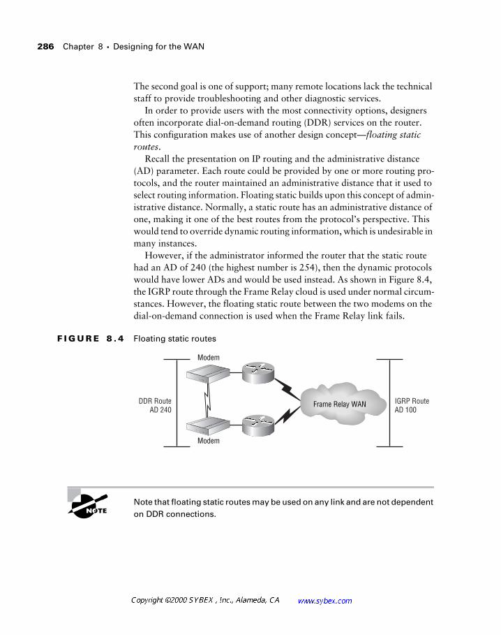
286 Chapter 8 � Designing for the WAN
The second goal is one of support; many remote locations lack the technical staff to provide troubleshooting and other diagnostic services.
In order to provide users with the most connectivity options, designers often incorporate dial-on-demand routing (DDR) services on the router. This configuration makes use of another design concept—floating static routes.
Recall the presentation on IP routing and the administrative distance (AD) parameter. Each route could be provided by one or more routing pro-tocols, and the router maintained an administrative distance that it used to select routing information. Floating static builds upon this concept of admin-istrative distance. Normally, a static route has an administrative distance of one, making it one of the best routes from the protocol’s perspective. This would tend to override dynamic routing information, which is undesirable in many instances.
However, if the administrator informed the router that the static route had an AD of 240 (the highest number is 254), then the dynamic protocols would have lower ADs and would be used instead. As shown in Figure 8.4, the IGRP route through the Frame Relay cloud is used under normal circum-stances. However, the floating static route between the two modems on the dial-on-demand connection is used when the Frame Relay link fails.
F I G U R E 8 . 4 Floating static routes
Note that floating static routes may be used on any link and are not dependent on DDR connections.
DDR RouteAD 240
IGRP RouteAD 100
Frame Relay WAN
Modem
Modem
Network Design with ATM 287
Backup Interfaces
An alternative to floating static routes is the backup interface. Under this configuration, the router is instructed to bring up a link if the interface goes down. The backup interface is associated with the primary interface. While this configuration has merits, the use of floating static routes typically works better in Frame Relay configurations. This addresses the concern of failed PVCs—the link may remain up/up (interface is up/line protocol is up); how-ever, a switch failure in the cloud will collapse the PVC.
The Local Management Interface was designed to prevent this type of failure, yet there are specific scenarios that LMI cannot detect.
Since the router has no method for detecting this failure (unlike ATM OAM cells, discussed later in this chapter), it continues to believe that the interface is valid. The routing protocol may eventually record the fact that the link is unavailable, but this requires the use of a routing protocol, which adds overhead.
Network Design with ATM
Asynchronous Transfer Mode technology was developed to combine video, voice, and data in the network. The ATM Forum, a working group of vendors, developed a cell-based system for transporting these types of infor-mation. Cells are fixed in length, and therefore latency and delay can be determined and controlled accurately.
ATM provides many services for the network designer and should be considered in any wide area network design. This is especially true when con-sidering the integration of voice and data. An emerging trend in networking is to focus on the services that are provided by the network and not the meth-odology employed. This technique simplifies the business-to-technology modeling process. Business-to-technology modeling is a process that incor-porates the concepts presented in Chapter 1, where the business demands and needs are integrated into the technology and its abilities.
When selecting ATM as a WAN technology, there are two interesting issues that warrant careful consideration. First, every conversion from cell to
288 Chapter 8 � Designing for the WAN
frame requires processing and adds a small amount of latency. This is an important factor to consider when choosing a partial-mesh topology. The second consideration is vendor availability, especially with new features. For example, vendors deployed only IMA technology in mid-1999. Inverse multi-plexing for ATM (IMA) is a major feature for network designers to consider since it provides a middle ground between T1 and DS-3 circuits. In many locations, IMA is the only way to provide greater than T1 bandwidth in remote locations—IMA bonds multiple T1s into a single data conduit.
Virtual Path and Virtual Circuit Identifiers
Every ATM cell contains a virtual path identifier (VPI) and a virtual circuit identifier (VCI). These values are combined, depending on the switch con-figuration, to create unique conduit information for the cell. This is very sim-ilar to the DLCI in Frame Relay, although the difference between path and circuit does not apply in ATM. Frame Relay understands only the equivalent concept of circuit.
The virtual path identifier encompasses a large number of virtual circuit identifiers. A four-line roadway tunnel is one way to visualize this. Each lane is analogous to the VCI, and the tunnel itself is the VPI. The lanes can diverge at either end of the tunnel, but within the tunnel they are fixed to the single path.
Network Design in the Real-World: The Benefits of ATM
As networks have advanced, the lines between voice and data have blurred significantly. From a historical perspective, voice services and data have operated over separate circuits. When the two were integrated, it was via time division multiplexing (TDM), which maintained distinct channels for each service. Asynchronous Transfer Mode (ATM) allows for the true inte-gration of these services, in addition to video, so Cisco recommends that designers use ATM whenever possible. Thus far the marketplace has con-tinued to use Frame Relay and other technologies, yet providers are devel-oping better tariffs and offerings to make ATM more attractive. Vendors are also providing ATM in more regions and with more equipment options.
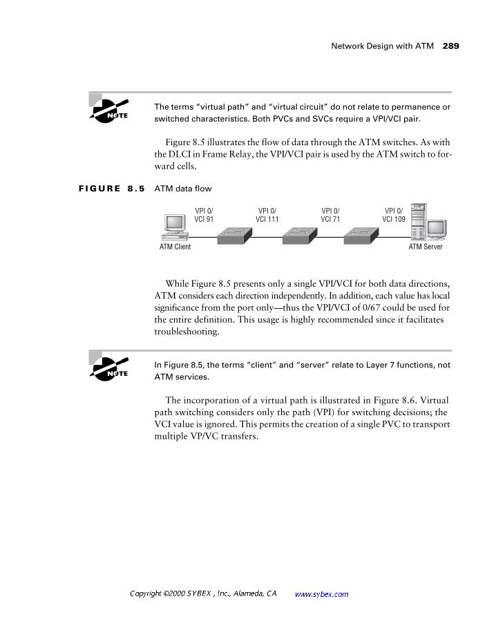
Network Design with ATM 289
The terms “virtual path” and “virtual circuit” do not relate to permanence or switched characteristics. Both PVCs and SVCs require a VPI/VCI pair.
Figure 8.5 illustrates the flow of data through the ATM switches. As with the DLCI in Frame Relay, the VPI/VCI pair is used by the ATM switch to for-ward cells.
F I G U R E 8 . 5 ATM data flow
While Figure 8.5 presents only a single VPI/VCI for both data directions, ATM considers each direction independently. In addition, each value has local significance from the port only—thus the VPI/VCI of 0/67 could be used for the entire definition. This usage is highly recommended since it facilitates troubleshooting.
In Figure 8.5, the terms “client” and “server” relate to Layer 7 functions, not ATM services.
The incorporation of a virtual path is illustrated in Figure 8.6. Virtual path switching considers only the path (VPI) for switching decisions; the VCI value is ignored. This permits the creation of a single PVC to transport multiple VP/VC transfers.
ATM ServerATM Client
VPI 0/VCI 91
VPI 0/VCI 111
VPI 0/VCI 71
VPI 0/VCI 109
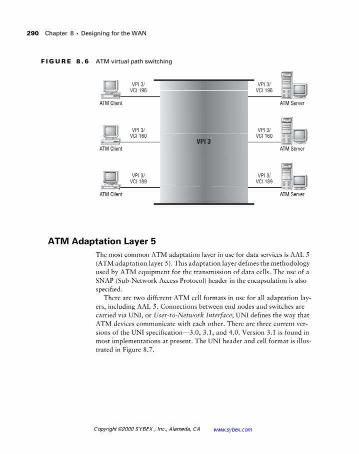
290 Chapter 8 � Designing for the WAN
F I G U R E 8 . 6 ATM virtual path switching
ATM Adaptation Layer 5
The most common ATM adaptation layer in use for data services is AAL 5 (ATM adaptation layer 5). This adaptation layer defines the methodology used by ATM equipment for the transmission of data cells. The use of a SNAP (Sub-Network Access Protocol) header in the encapsulation is also specified.
There are two different ATM cell formats in use for all adaptation lay-ers, including AAL 5. Connections between end nodes and switches are carried via UNI, or User-to-Network Interface; UNI defines the way that ATM devices communicate with each other. There are three current ver-sions of the UNI specification—3.0, 3.1, and 4.0. Version 3.1 is found in most implementations at present. The UNI header and cell format is illus-trated in Figure 8.7.
ATM ServerATM Client
VPI 3/VCI 196
VPI 3/VCI 196
ATM ServerATM Client
VPI 3/VCI 160
VPI 3/VCI 160
ATM ServerATM Client
VPI 3/VCI 189
VPI 3/VCI 189
VPI 3
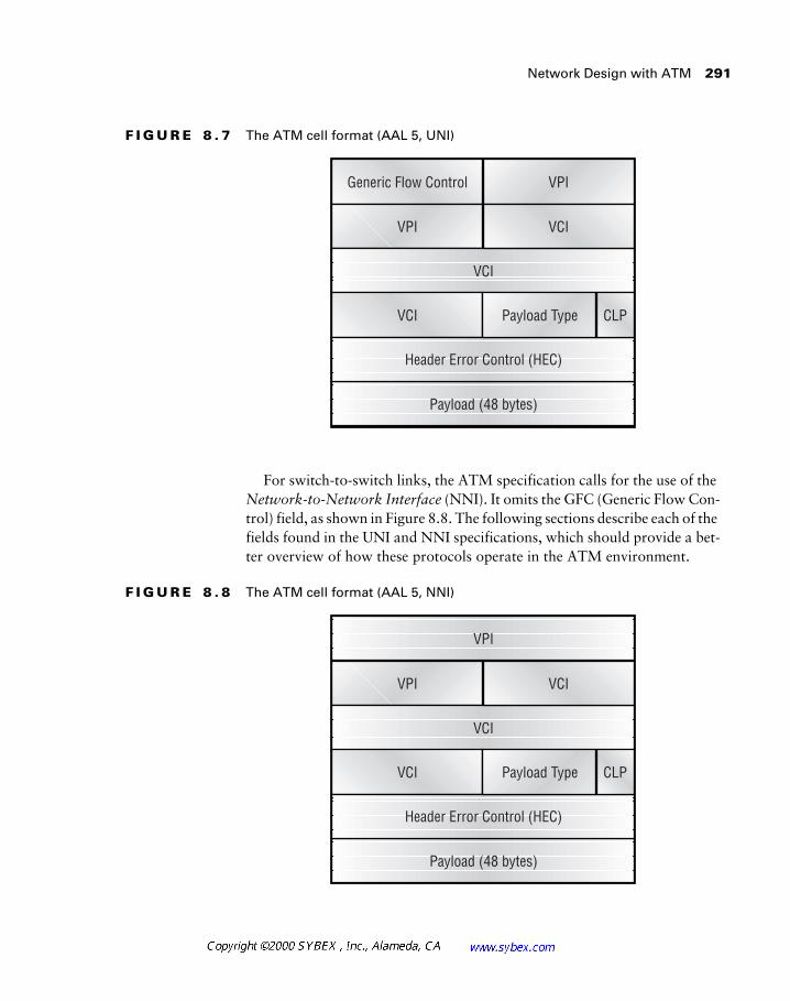
Network Design with ATM 291
F I G U R E 8 . 7 The ATM cell format (AAL 5, UNI)
For switch-to-switch links, the ATM specification calls for the use of the Network-to-Network Interface (NNI). It omits the GFC (Generic Flow Con-trol) field, as shown in Figure 8.8. The following sections describe each of the fields found in the UNI and NNI specifications, which should provide a bet-ter overview of how these protocols operate in the ATM environment.
F I G U R E 8 . 8 The ATM cell format (AAL 5, NNI)
Generic Flow Control
VPI
VCI
VCI
Payload (48 bytes)
VPI
VCI
Payload Type CLP
Header Error Control (HEC)
VPI
VCI
VPI
VCI
Payload (48 bytes)
VCI
Payload Type CLP
Header Error Control (HEC)
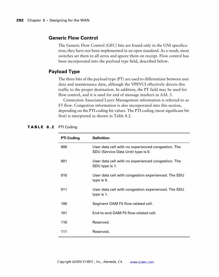
292 Chapter 8 � Designing for the WAN
Generic Flow Control
The Generic Flow Control (GFC) bits are found only in the UNI specifica-tion; they have not been implemented in an open standard. As a result, most switches set them to all zeros and ignore them on receipt. Flow control has been incorporated into the payload type field, described below.
Payload Type
The three bits of the payload type (PT) are used to differentiate between user data and maintenance data, although the VPI/VCI effectively directs this traffic to the proper destination. In addition, the PT field may be used for flow control, and it is used for end of message markers in AAL 5.
Connection Associated Layer Management information is referred to as F5 flow. Congestion information is also incorporated into this section, depending on the PTI coding bit values. The PTI coding (most significant bit first) is interpreted as shown in Table 8.2.
T A B L E 8 . 2 PTI Coding
PTI Coding Definition
000 User data cell with no experienced congestion. The SDU (Service Data Unit) type is 0.
001 User data cell with no experienced congestion. The SDU type is 1.
010 User data cell with congestion experienced. The SDU type is 0.
011 User data cell with congestion experienced. The SDU type is 1.
100 Segment OAM F5 flow-related cell.
101 End-to-end OAM F5 flow-related cell.
110 Reserved.
111 Reserved.
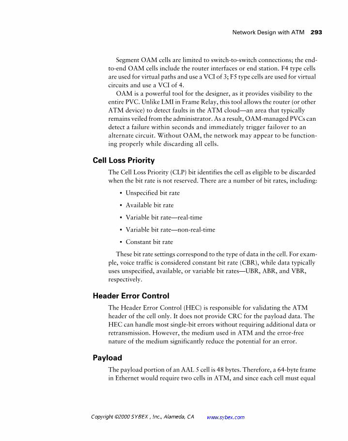
Network Design with ATM 293
Segment OAM cells are limited to switch-to-switch connections; the end-to-end OAM cells include the router interfaces or end station. F4 type cells are used for virtual paths and use a VCI of 3; F5 type cells are used for virtual circuits and use a VCI of 4.
OAM is a powerful tool for the designer, as it provides visibility to the entire PVC. Unlike LMI in Frame Relay, this tool allows the router (or other ATM device) to detect faults in the ATM cloud—an area that typically remains veiled from the administrator. As a result, OAM-managed PVCs can detect a failure within seconds and immediately trigger failover to an alternate circuit. Without OAM, the network may appear to be function-ing properly while discarding all cells.
Cell Loss Priority
The Cell Loss Priority (CLP) bit identifies the cell as eligible to be discarded when the bit rate is not reserved. There are a number of bit rates, including:
� Unspecified bit rate
� Available bit rate
� Variable bit rate—real-time
� Variable bit rate—non-real-time
� Constant bit rate
These bit rate settings correspond to the type of data in the cell. For exam-ple, voice traffic is considered constant bit rate (CBR), while data typically uses unspecified, available, or variable bit rates—UBR, ABR, and VBR, respectively.
Header Error Control
The Header Error Control (HEC) is responsible for validating the ATM header of the cell only. It does not provide CRC for the payload data. The HEC can handle most single-bit errors without requiring additional data or retransmission. However, the medium used in ATM and the error-free nature of the medium significantly reduce the potential for an error.
Payload
The payload portion of an AAL 5 cell is 48 bytes. Therefore, a 64-byte frame in Ethernet would require two cells in ATM, and since each cell must equal
294 Chapter 8 � Designing for the WAN
53 bytes, the ATM cell is padded. This leads to some concerns in the net-working arena that there is too much overhead in ATM when linking frame-based networks.
Designers should note that ATM does not provide error checking on the payload section of the cell; it leaves that responsibility to the upper-layer protocols.
Permanent Virtual Circuits
The simplest ATM designs make use of permanent virtual circuits (PVCs). In advance of the anticipated need, an administrator defines these virtual con-nections. This is identical to PVCs in Frame Relay.
The advantage to PVCs is that there is no signaling required for call setup, and all circuits are available for data at all times. Unfortunately, this also requires manual configuration of the circuits—a step that can become cum-bersome as the network increases in size. Traditionally, the administrator must manually configure each VPI/VCI path statement at each switch in the
Network Design in the Real World: Other ATM Adaptation Layers
There are five adaptation layers in the ATM specifications, although layers 3 and 4 are generally regarded as a single layer. AAL 1 is typically used for voice traffic, while AAL 2 is rarely used at all.
Due to their similarities, AAL 3 and 4 are frequently listed as AAL 3/4. Unlike AAL 5, AAL 3/4 incorporates a message identifier, a sequence number, and a cyclical redundancy check in each cell. This reduces the payload portion of the cell to 44 bytes.
Because of this overhead, there are some advantages to AAL 3/4. Receivers can reassemble cells based on the message identifier and the sequence number, which permits reconciliation of out-of-sequence frames. While this overhead is beneficial for connectionless configurations, it also results in a significant performance penalty. In addition to the added cell tax, or the overhead per cell, the segmentation and reassembly process is substan-tially more involved, which can lead to further delay. As a result, AAL 3/4 is not as popular as AAL 5.
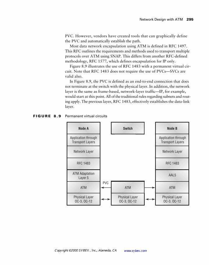
Network Design with ATM 295
PVC. However, vendors have created tools that can graphically define the PVC and automatically establish the path.
Most data network encapsulation using ATM is defined in RFC 1497. This RFC outlines the requirements and methods used to transport multiple protocols over ATM using SNAP. This differs from another RFC-defined methodology, RFC 1577, which defines encapsulation for IP only.
Figure 8.9 illustrates the use of RFC 1483 with a permanent virtual cir-cuit. Note that RFC 1483 does not require the use of PVCs—SVCs are valid also.
In Figure 8.9, the PVC is defined as an end-to-end connection that does not terminate at the switch with the physical layer. In addition, the network layer is the same as frame-based, network-layer traffic—IP, for example, would start at this point. All of the traditional rules regarding subnets and rout-ing apply. The previous layer, RFC 1483, effectively establishes the data-link layer.
F I G U R E 8 . 9 Permanent virtual circuits
Node A
Application throughTransport Layers
Application throughTransport Layers
PVC
RFC 1483
ATM AdaptationLayer 5
ATM
Physical LayerOC-3, OC-12
Switch
ATM
Physical LayerOC-3, OC-12
Node B
ATM
Physical LayerOC-3, OC-12
RFC 1483
Network Layer Network Layer
AAL5
296 Chapter 8 � Designing for the WAN
On Cisco routers, the network is associated with the PVC on a subinterface level, and designs are point-to-point.
As with Frame Relay, ATM PVCs are typically configured with two band-width parameters. The maximum cell rate is referred to as the Peak Cell Rate (PCR), while the amount of bandwidth available for data is called the Sus-tained Cell Rate (SCR). The SCR is analogous to the CIR in Frame Relay (discussed earlier in this chapter), and under the FRF.8 specifications, the two are somewhat interchangeable. (The FRF.8 and FRF.5 specifications define the methods by which ATM and Frame Relay traffic are interchanged.)
Switched Virtual Circuits
Unlike permanent virtual circuits, switched virtual circuits (SVCs) are not established in advance. Rather, the switches are responsible for dynamically establishing the circuit through the network. In most other ways, SVCs are identical to PVCs. For example, SVCs may be used for nonbroadcast multi-access network designs (point-to-multipoint) or point-to-point configurations.
Figure 8.10 illustrates the components involved in establishing a switched virtual circuit. The Q.2931 standard is used for signaling information between the switch and ATM clients, which are labeled NSAP (Network Ser-vice Access Point) A and NSAP B. The signaling between single end nodes is called UNI; switches signal each other with NNI, as described previously.
The illustration in Figure 8.10 also includes the SSCOP layer, or Service-Specific Convergence Protocol. This protocol is responsible for reassembling the cells on the signaling channel. This is different from the segmentation and reassembly process in AAL 5—the cells serviced by SSCOP are usually mes-sages used in the management of the ATM network and not user data.
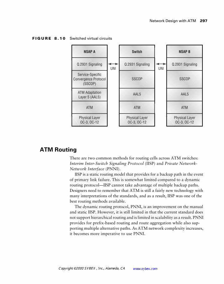
Network Design with ATM 297
F I G U R E 8 . 1 0 Switched virtual circuits
ATM Routing
There are two common methods for routing cells across ATM switches: Interim Inter-Switch Signaling Protocol (IISP) and Private Network-Network Interface (PNNI).
IISP is a static routing model that provides for a backup path in the event of primary link failure. This is somewhat limited compared to a dynamic routing protocol—IISP cannot take advantage of multiple backup paths. Designers need to remember that ATM is still a fairly new technology with many interpretations of the standards, and as a result, IISP was one of the best routing methods available.
The dynamic routing protocol, PNNI, is an improvement on the manual and static IISP. However, it is still limited in that the current standard does not support hierarchical routing and is limited in scalability as a result. PNNI provides for prefix-based routing and route aggregation while also sup-porting multiple alternative paths. As ATM network complexity increases, it becomes more imperative to use PNNI.
NSAP A
Q.2931 SignalingUNI UNI
Service-SpecificConvergence Protocol
(SSCOP)
ATM AdaptationLayer 5 (AAL5)
ATM
Physical LayerOC-3, OC-12
Switch
Q.2931 Signaling
SSCOP
AAL5
ATM
Physical LayerOC-3, OC-12
NSAP B
Q.2931 Signaling
ATM
Physical LayerOC-3, OC-12
SSCOP
AAL5
298 Chapter 8 � Designing for the WAN
Both routing protocols support e.164 addresses, which are used in public ATM networks, and NSAP addresses, which are used in private installations. NSAP addressing is the 20-octet addressing format, while e.164 is a 10-digit number similar to phone numbers in North America. Some e.164 addresses have additional bits/digits, as shown later in the SMDS section.
The design models for ATM are very similar to those used in traditional networks. For example, configurations may follow the hierarchical model or operate in a start topology. Most ATM tariffs are quite expensive at present; however, substantial discounts may be found in local installations. Unlike most other network technologies, it is very important to avoid congestion in ATM networks. This is due to the impact of a single lost cell on the data flow—a lost cell may require 20 cells to repeat the frame. All 20 cells will be retransmitted even though only one cell was lost to congestion. This adds to the original congestion problem and results in greater data loss.
Cisco’s StrataCom Switches
In the years following the acquisition of StrataCom, Cisco struggled with developing and marketing this powerful product. As of this writing, pundits continue to criticize the product and the strategic direction presented by the company regarding this system. Nonetheless, the platform is still competing with alternative offerings, including Nortel’s Passport. The criticisms of the past may return should Cisco falter in its current efforts to link the product with the rest of the company’s offerings or should Cisco fail to add addi-tional features to bring it in line with the competition.
However, in recent months the product has successfully competed against rivals and, more important in this context, the CID exam contains a number of questions regarding this platform. It is very important to note that the cur-rent exam objectives do not explicitly note the StrataCom product line.
The StrataCom product line provides a number of network services. These include the following:
� Cell-based trunk links are provided with either standard 53-byte ATM cells or the 24-byte FastPacket cell configurations. FastPacket cells are proprietary.
� Dial-up services are provided with the Intelligent Network Server (INS). This independent processing system supports dial-up Frame Relay, voice-switched circuits, and ATM SVCs.
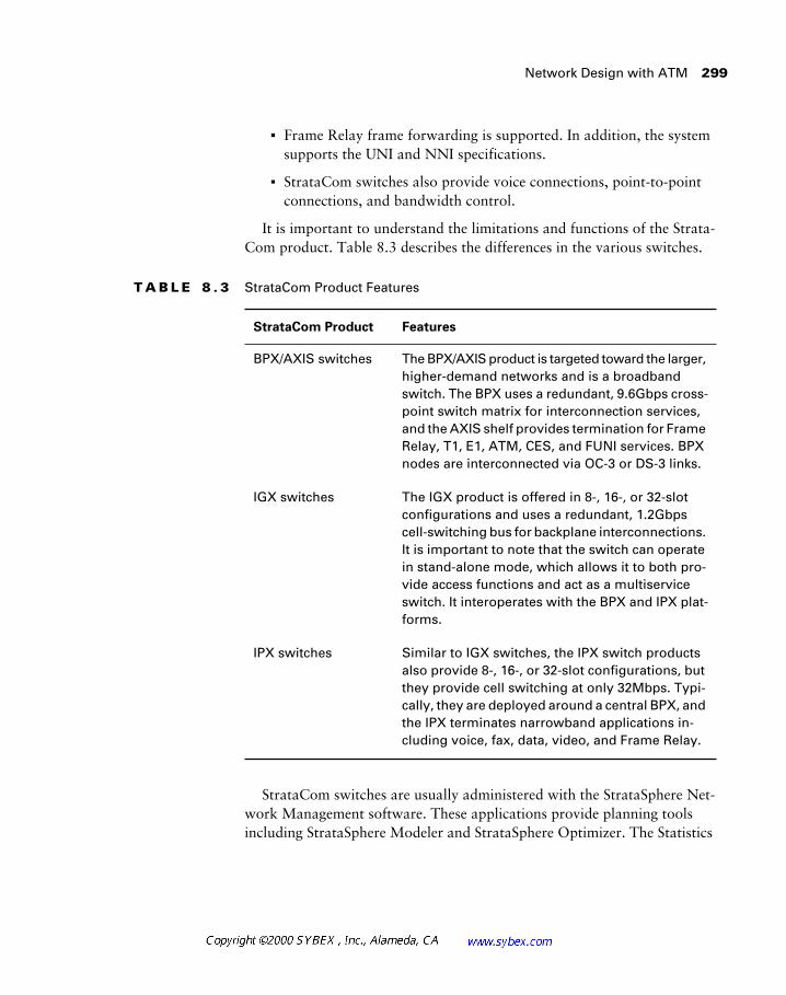
Network Design with ATM 299
� Frame Relay frame forwarding is supported. In addition, the system supports the UNI and NNI specifications.
� StrataCom switches also provide voice connections, point-to-point connections, and bandwidth control.
It is important to understand the limitations and functions of the Strata-Com product. Table 8.3 describes the differences in the various switches.
StrataCom switches are usually administered with the StrataSphere Net-work Management software. These applications provide planning tools including StrataSphere Modeler and StrataSphere Optimizer. The Statistics
T A B L E 8 . 3 StrataCom Product Features
StrataCom Product Features
BPX/AXIS switches The BPX/AXIS product is targeted toward the larger, higher-demand networks and is a broadband switch. The BPX uses a redundant, 9.6Gbps cross-point switch matrix for interconnection services, and the AXIS shelf provides termination for Frame Relay, T1, E1, ATM, CES, and FUNI services. BPX nodes are interconnected via OC-3 or DS-3 links.
IGX switches The IGX product is offered in 8-, 16-, or 32-slot configurations and uses a redundant, 1.2Gbps cell-switching bus for backplane interconnections. It is important to note that the switch can operate in stand-alone mode, which allows it to both pro-vide access functions and act as a multiservice switch. It interoperates with the BPX and IPX plat-forms.
IPX switches Similar to IGX switches, the IPX switch products also provide 8-, 16-, or 32-slot configurations, but they provide cell switching at only 32Mbps. Typi-cally, they are deployed around a central BPX, and the IPX terminates narrowband applications in-cluding voice, fax, data, video, and Frame Relay.
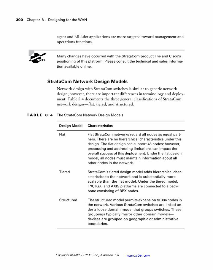
300 Chapter 8 � Designing for the WAN
agent and BILLder applications are more targeted toward management and operations functions.
Many changes have occurred with the StrataCom product line and Cisco’s positioning of this platform. Please consult the technical and sales informa-tion available online.
StrataCom Network Design Models
Network design with StrataCom switches is similar to generic network design; however, there are important differences in terminology and deploy-ment. Table 8.4 documents the three general classifications of StrataCom network designs—flat, tiered, and structured.
T A B L E 8 . 4 The StrataCom Network Design Models
Design Model Characteristics
Flat Flat StrataCom networks regard all nodes as equal part-ners. There are no hierarchical characteristics under this design. The flat design can support 48 nodes; however, processing and addressing limitations can impact the overall success of this deployment. Under the flat design model, all nodes must maintain information about all other nodes in the network.
Tiered StrataCom’s tiered design model adds hierarchical char-acteristics to the network and is substantially more scalable than the flat model. Under the tiered model, IPX, IGX, and AXIS platforms are connected to a back-bone consisting of BPX nodes.
Structured The structured model permits expansion to 384 nodes in the network. Various StrataCom switches are linked un-der a loose domain model that groups switches. These groupings typically mirror other domain models—devices are grouped on geographic or administrative boundaries.
Network Design with SMDS 301
Network Design with SMDS
Switched Multimegabit Data Service (SMDS) was designed to provide the performance characteristics and connectivity features of local area networks in the WAN. This was accomplished by using a connectionless, on-demand transport based on the 802.6 MAN standard. However, the under-lying structure of SMDS is cell-based ATM, and it uses ATM AAL 3/4. Recall that data ATM networks use AAL 5 in most installations.
It is unfortunate that SMDS technology did not succeed. The protocol offered network designers many benefits. For example, changes were very simple, and additional nodes could be added quickly. In addition, all inter-faces in the same SMDS region were addressed in the same subnet, and all stations had direct, connectionless access to every other node. However, SMDS never received widespread adoption, and many carriers avoided the technology in favor of Frame Relay or ATM. Customers also avoided the technology, though this was primarily due to the high cost of equipment and low availability. Today it is virtually impossible to order SMDS—ven-dors will direct you to ATM or Frame Relay.
While configured as a connectionless topology, SMDS offered a reason-able degree of security for corporations. Addresses were entered into screen-ing and validation tables to permit connectivity between nodes. This isolated each company logically within the switch, yet inter-company SMDS commu-nications could be enabled with a minor table modification.
Broadcasts from the source router would reach all other routers—the packet automatically being forwarded by the SMDS switch to all routers in the network. This was accomplished with group addressing. SMDS addresses in North America were assigned like traditional analog phone numbers; however, they were prefixed with a C or an E. C addresses are for individual nodes, and E addresses are used within a group for the group address. The group address for an SMDS network in Chicago might appear as e131.2555.1212, for example. Packets sent to the group address are for-warded to all nodes in the subnet (as defined in the SMDS switch). This sim-plified processing on the source router—recall that in Frame Relay, the router repeated the broadcast for each PVC.
302
Chapter 8 �
Designing for the WAN
The router sends only one copy of the packet to the group address. The net-work/switch is responsible for distributing and repeating that packet to all members of the group. The network/switch will not transmit the packet back
to the sender, even though the sender is a member of the group.
SMDS required the use of an SMDSU (SMDS Unit) or SDSU (SMDS Data Service Unit). Since SMDS never attained the volume found with Frame Relay and other WAN technologies, it is understandable that these DSUs would have a higher cost.
SMDS supports a number of upper-layer protocols, including:
�
IP
�
IPX
�
AppleTalk
�
CLNS
�
XNS
�
DECNet
�
Vines
�
Transparent bridging
This wide array of protocol support was one of the advantages of SMDS. For example, IP could use the multicast function in SMDS to per-form ARPs, which saved a great deal of time normally required for manual configuration.
The following output demonstrates a typical SMDS interface configura-tion. Note that both static and multicast entries are present—the adminis-trator could rely on multicasts to the group address for all traffic, yet in this instance static entries for each element were chosen to reduce queries and to facilitate troubleshooting. Also note that both IP and IPX are configured for this SMDS group.
interface Serial1/1
description SMDS Interface
ip address 10.1.2.1 255.255.255.0
encapsulation smds
Summary 303
smds address c141.5555.1234
no smds dxi-mode
smds static-map ip 10.1.2.11 c141.5555.1111
smds static-map ip 10.1.2.20 c141.5555.1120
smds static-map ipx 100.0000.3048.e909 c141.5555.1120
smds multicast IP e141.5555.0001 10.1.2.0 255.255.255.0
smds multicast ARP e141.5555.0001 10.1.2.0 255.255.255.0
smds multicast NOVELL e141.5555.0001
smds enable-arp
ipx network 100
ipx output-sap-filter 1000
As with other WAN technologies, SMDS should be evaluated on availability, equipment, and cost factors. Note that many vendors, including Pacific Bell/Southwest Bell, will no longer provision SMDS for new installations.
Summary
This chapter provided a substantial background into three different WAN technologies: Frame Relay, ATM, and SMDS. It also provided an overview of dedicated leased lines, which are also common in WAN design. As with most factors in network design, architects need to be familiar with the scalability and costs associated with their designs while considering the business factors and services that are required.
Specifically, readers should come away from this chapter with a comfort-able understanding of the following:
� The WAN design factors
� Serial line encapsulations
� Frame Relay
� LMI
� Frame Relay PVCs
304 Chapter 8 � Designing for the WAN
� Inverse ARP
� Nonbroadcast multiaccess networks
� ATM
� Cisco’s StrataCom product line
� Switched virtual circuits
� Permanent virtual circuits
� The AAL 5 specification
� The ATM cell format
� SMDS
The next chapter builds upon some of these concepts as it addresses the remote access technologies, including ISDN and X.25. Generally, these ser-vices are of lower bandwidth than ATM and Frame Relay.
Review Questions
305
Review Questions
1.
In a flat configuration, the StrataCom switch can support how many ports?
A.
12
B.
24
C.
48
D.
192
2.
Which product would be most appropriate for terminating low-bandwidth user services?
A.
IPX
B.
IGX
C.
BPX
D.
eIPX
3.
Which WAN technology is best suited for integrating voice, video, and data?
A.
Frame Relay
B.
SMDS
C.
ATM
D.
ISDN
4.
Which of the following WAN technologies is being phased out?
A.
ATM
B.
SMDS
C.
Frame Relay
D.
T1

306 Chapter 8 � Designing for the WAN
5. A cell in ATM AAL 5 is:
A. 48 bytes long
B. 53 bytes long
C. Variable in length, but never more than 48 bytes long
D. Variable in length, up to a maximum of 1514 bytes
6. The payload section of an AAL 3/4 cell is:
A. 5 bytes
B. 44 bytes
C. 48 bytes
D. 53 bytes
7. The header in AAL 5 is:
A. 5 bytes
B. 9 bytes
C. 48 bytes
D. 53 bytes
8. Which of the following is not true of an ATM cell formatted within the AAL 5 specification?
A. It operates with PVC and SVC circuits.
B. It provides 48 bytes per cell for payload.
C. It provides 5 bytes per cell for header.
D. It provides a checksum for the cell payload.

Review Questions 307
9. In AAL 5, error checking includes:
A. The ATM header
B. The ATM payload
C. Both the ATM header and the ATM payload
D. Neither the ATM header nor the ATM payload
10. Frame Relay provides a better pricing model for designers because of which features?
A. Single destination per physical interface and per-mile charges
B. Multiple destinations per physical interface and per-mile charges
C. Multiple destinations per physical interface and distance-insensitive charges
D. Single destination per physical interface and distance-insensitive charges
11. The BPX switch employs which of the following?
A. A 1.2Gbps frame-based backplane
B. A 3.6Gbps backplane link via the Phoenix ASIC
C. A redundant 1.2Gbps cell-switching bus
D. A redundant 9.6Gbps crosspoint switch matrix
12. StrataCom switches do not provide which of the following services?
A. ATM
B. Video
C. FDDI
D. Voice

308 Chapter 8 � Designing for the WAN
13. Rather than disabling split-horizon, the designer of a Frame Relay net-work could design:
A. A full mesh with separate subnets for each PVC
B. A partial mesh with separate subnets for each PVC
C. A full mesh with a single subnet
D. A partial mesh with a single subnet
14. Which of the following is not an encapsulation for Frame Relay?
A. AAL5SNAP
B. Frame Relay Forum LMI
C. ITU-T Q.933 Annex A
D. ANSI T1.617 Annex D
15. Inverse ARP performs which function?
A. Dynamic addressing of router interfaces
B. Dynamic mapping of Layer 3 addresses
C. Frame Relay control signaling
D. ATM LANE address mapping
16. NNI cells do not contain which of the following?
A. VPI
B. VCI
C. GFC
D. HEC
17. The AAL 3/4 specification provides more user bandwidth than AAL 5. True or false?
A. True
B. False
Review Questions 309
18. The structured design model for StrataCom switches employs which concept?
A. Hierarchical domain model that supports up to 384 nodes
B. Full-mesh model that supports up to 384 nodes
C. Hierarchical domain model that supports up to 64 nodes
D. Partial-mesh model that supports up to 64 nodes
19. DLCIs must be the same throughout the entire PVC. True or false?
A. True
B. False
20. Generic Flow Control provides which of the following features?
A. Congestion control
B. Buffering control
C. Path determination for congestion control
D. None of the above

310 Chapter 8 � Designing for the WAN
Answers to Review Questions
1. C.
2. A.
3. C.
4. B.
5. B.
6. B.
7. A.
8. D.
9. A.
10. C.
11. D.
12. C.
13. B.
14. A.
15. B.
16. C.
17. B.
18. A.
19. B.
20. D.
Chapter
9Remote Access Network Design
CISCO INTERNETWORK DESIGN EXAM OBJECTIVES COVERED IN THIS CHAPTER:
� Design scalable internetwork WAN nonbroadcast multi-
access X.25.
� Design scalable, robust internetwork WAN with X.25
subinterface configuration.
� Use X.25 switching to provide X.25 service over an integrated IP
backbone.
� Explain ISDN services.
� Examine a customer’s requirements and recommend
appropriate ISDN solutions.
� Construct an ISDN design that conserves bandwidth and is cost
effective.
� Examine a client’s requirements and recommend appropriate
point-to-point and asynchronous WAN solutions.
� Choose appropriate link encapsulation for point-to-point
circuits.
While the technologies presented in this chapter are differ-ent from the WAN systems discussed in Chapter 8, readers should find some similarities between them. All WAN systems ultimately introduce factors that are not present in LAN designs—sometimes these factors are significant. Consider the fact that most WAN solutions reduce the amount of control availed to the administrator. This loss of control may be due to a partnership with a telecommunications provider or to end-user activity. Either factor can greatly complicate troubleshooting and support.
Another common factor in remote access and WAN solutions is perfor-mance. While it is possible to obtain OC-48 SONET (Synchronous Optical Network) rings (yielding over 2Gbps) for WAN connectivity, these solutions are also very costly (up to and exceeding $30,000 a month, depending on distance). Remote-access solutions typically utilize significantly slower con-nection methods, including X.25, ISDN, and standard telephone services (PSTN/POTS or Public Switched Telephone Network/plain old telephone service). Therefore, designers should work with users and application sup-port staff to minimize the demands on the remote access solution, thereby providing the greatest performance for users.
This chapter will address X.25 and ISDN technologies in detail. It will also present the various ways remote users access the corporate network, including remote gateways, remote control, and remote nodes.
This chapter will include a section on xDSL technologies as well. While xDSL is not on the current CID examination, the quick growth of this trans-port technology will certainly play a role in future network designs.
Network Design with X.25 313
Network Design with X.25
The X.25 protocol was intended to address the connectivity demands of low-bandwidth, poor-quality connections. As a result, the protocol con-tains a significant amount of overhead related to error-checking that is typi-cally unnecessary in modern networks. However, it is also a widely available protocol, so network designers may likely need to integrate legacy X.25 into more modern network designs. The protocol remains quite prevalent in some countries and in the telecommunications industry as well. Companies with networks outside the US and Japan should consider X.25 for lower cost, lower bandwidth connections, especially as a transport for IP traffic—however, X.25 will transport most protocols.
The basic tenet of X.25 is that the protocol should be reliable. Therefore, the protocol is based on LAPB (Link Access Procedure, Balanced), which provides flow control and reliable transport at the data-link layer. One fea-ture in X.25 is the use of channels, which are effectively logical virtual cir-cuits. As indicated previously, compared to other protocols, including Frame Relay, X.25 has very low throughput and high latency—a characteristic of packet-relay transports. While most X.25 implementations connect to a public network, a significant number of private systems exist. These are fre-quently found in telecommunications and financial environments, although ISDN, xDSL, and low-bandwidth Frame Relay are slowly eroding this mar-ket share.
In a Cisco-based network design, the X.25 protocol is used to create WAN links where the carrier provides the DCE (data circuit-terminating equipment) and the router takes on the role of the DTE (data terminal equip-ment). However, the router can be configured as the DCE when necessary. Connections are established by defining an X.121 address in the router. X.121 addresses are comprised of a four-digit Data Network Identification Code (DNIC) and a National Terminal Number (NTN), which may be up to 10 digits in length. It is important to note that most X.25 services are billed on a per-packet basis, so most designers use static routes and filters to limit the traffic on the network.
Most designers without X.25 experience typically have some Frame Relay expertise. This expertise is beneficial, as Frame Relay compares with X.25 from an overall topology perspective. The network core can be con-figured via X.25, but it is generally recommended that a full-mesh design
314 Chapter 9 � Remote Access Network Design
be implemented. In addition, careful consideration should be given to over-subscription, as bandwidth is limited. Designers also need to consider X.25 under the same guidelines as any NBMA (nonbroadcast multiaccess) con-figuration, which was covered in the Frame Relay section of the previous chapter.
Cisco introduced subinterface support for X.25 in IOS version 10.0. This eliminated the NBMA factors of partial-mesh connectivity and split-horizon, so the designer can provide full connectivity with a partial-mesh configura-tion. As with other subinterfaces, each link is a different network.
The router can also provide the functions of an X.25 switch via its serial ports. This allows connectivity between two packet assembler/disassembler (PAD) devices. Unfortunately, X.25 and LAPB are the only protocols sup-ported on the link, which precludes other encapsulations. Both PVC (perma-nent virtual circuit) and SVC (switched virtual circuit) links are supported.
Network Design with ISDN
Integrated Services Digital Network (ISDN) technology was developed in large part from the conversion to digital networks from analog switches by the telephone companies in North America, which at the time was AT&T for the United States. This conversion, which started in the 1960s, resulted in the following features:
� Clearer, cleaner signals.
� Compressible voice, resulting in better trunking utilization.
� Longer distances between switching devices.
� Value-added features, including caller ID and three-way calling.
� Greater bandwidth—a single connection to the telephone company can service more than one phone number.
� Elimination of load coils and amplifiers in the network.
ISDN was originally conceived as a means to move the digital network into the home, where a single ISDN connection would provide two standard phone lines and digital services for data. This migration from the analog phone would continue to use the existing copper wire plant while adding ser-vices that would ultimately increase revenues.
Network Design with ISDN 315
Unfortunately, users failed to accept ISDN in the numbers desired. This was especially true in the United States, where installation problems, service availability, and pricing all combined to hinder acceptance.
Standard ISDN service is popular for videoconferencing and as a residen-tial connection to the Internet. Cable modems and xDSL technologies will probably replace this market in the 21st century, however.
Most ISDN installations in remote locations use the Basic Rate Interface (BRI), offering users two B channels for user data and a single D channel (16Kbps) for signaling. This provides a total bandwidth of 144Kbps; how-ever, each B channel is only 64Kbps, for a total user bandwidth of 128Kbps.
ISDN BRI is really a 192Kbps circuit; the remaining bandwidth of 48Kbps is overhead. The physical frame in ISDN BRI is 48 bits, and the circuit sends 4,000 frames per second.
Host connections typically terminate with ISDN PRI (Primary Rate Inter-face) services, which use T1 circuits. This provides 23 B channels, and all sig-naling occurs on the D channel. Each channel is 64Kbps, for a total data rate of 1.535Mbps. The remaining bandwidth is overhead.
Designers should carefully review the costs associated with ISDN before committing to the technology. Since most tariffs are based on per-minute billing, bills in the thousands of dollars per month are not uncommon when improper configurations are deployed. This factor is the largest neg-ative regarding ISDN for telecommuting. Users will also notice that con-nections require a few seconds to be established—ISDN is not an always-on technology.
A D-channel-based service, called always-on ISDN, is available from some vendors. This provides up to 9.6Kbps for user data and can be used as a replacement for X.25 networks.
Communications over ISDN may use the Point-to-Point Protocol (PPP) where desired. PPP provides many additional services, including security via the Challenge Handshake Authentication Protocol (CHAP). PPP is an open standard defined in RFC 1661, and the PPP protocol, through the Link Con-trol Protocol (LCP), performs initial configuration. Multilink PPP may be used for B channel aggregation as well.
316 Chapter 9 � Remote Access Network Design
Multilink PPP (MP) performs a number of functions, but it primarily is responsible for the segmentation and sequencing of packets across multiple channels. This bonds the two B channels for a total of 128Kbps of user data, but it does not allow each channel to cross multiple chassis. The protocol is defined in RFC 1717, and it adds four bytes of overhead to each packet on the link. Network designers may find this function useful in videoconferenc-ing applications; however, it is also applicable for remote data connectivity.
The Multilink Multichassis PPP protocol (MMP) is another protocol that combines B channels. MMP operates across multiple routers and access serv-ers and is more scalable than the standard Multilink Protocol. Various B channels can span numerous chassis, allowing for larger, more scalable access farms and better redundancy options, since the failure of a single switch may not result in the loss of a session. When additional capacity is needed for a cluster, an administrator need add only another peer access device.
MMP relies on an MMP process server to reassemble the calls. One pos-sible implementation of this would include a 4700 router fronted with multiple AS5200s. The AS5200s combine to create a logical federation called stack-group peers, and these peers use the Stackgroup Bidding Protocol (SGBP) to elect a process server. SGBP is a proprietary protocol. Although MMP may be used similarly to MP, the multichassis nature of the protocol allows for greater scalability and aggregate bandwidth. The SGBP process selects resources based on previously existing sessions and processor load.
ISDN may also be used for L2F (Layer 2 Forwarding Protocol), PPTP (Point-to-Point Tunneling Protocol), and L2TP (Layer 2 Tunneling Protocol) tunnels, which are described in Chapter 11. These secure conduits are ideal for Internet connectivity; however, they may also be used in private net-works. One application for tunnels includes telecommuting—rather than having all users call a central, long-distance number, they can call a local point-of-presence and pay for a local call. The point-of-presence may be pri-vate and be maintained by the corporation or an ISP on the Internet. This concept is used for Virtual Private Network (VPN) solutions.
Remote Access
Over the years, users have demanded access to corporate LANs from their homes, hotel rooms, and customer sites. These requirements depart sig-nificantly from the fairly comfortable and controlled structure of the local area network.
Remote Access 317
In fact, many companies have decided to address remote connectivity with VPNs or with a combination of services that are outsourced to a pro-vider. Outsourcing is a good way to control costs, although the costs are gen-erally higher than with internally administered remote access solutions. This setup works in most corporations because hiring full-time personnel is very costly. Frequently, outsourced solutions can also decrease communications costs, which are recurring and can quickly overrun the best budgets, as the major telecommunications providers maintain points-of-presence in virtu-ally all calling areas. For the corporate user, the call into the remote-access system is a local one rather than a long-distance or 800 call, each of which costs the corporation substantially more.
Network designers need a thorough understanding of the remote connec-tivity options for either outsourcing or corporate-provided solutions. These solutions incorporate remote nodes, remote gateways, and remote control. However, this text will also incorporate remote users and their requirements into the mix.
It is important to note that most of these solutions are still deployed on standard telephone services, although some deployments use ISDN. Within the first few years of the 21st century, it is likely that cable modem and xDSL solutions will also be incorporated into remote-access deployments, and these technologies will likely replace ISDN and POTS.
Designers need to realize the limitations that come with any of these trans-port technologies. For example, standard telephone services are slow, but they are also universally available. Solutions based on DSL are fast and com-paratively cheap compared to ISDN and analog dial-up (based on band-width), but they must be pre-installed and are fixed in location at the remote end. While this makes the higher speed solution less attractive to remote users who travel, it would be an ideal solution for an at-home telecommuter.
Remote Gateway
Remote gateways are designed to solve a single remote access need, and as a result they can be fairly inexpensive. The most common remote gateways are used for e-mail, but they can be configured to provide other services as well. A remote gateway is a remote-access device that services a single application.
The key to remote gateway solutions is that they generally do not scale because the remote gateway device typically processes the application in addition to the remote session. Therefore, the designer may address a single
318 Chapter 9 � Remote Access Network Design
need quickly without building in scalability. As a result, the designer select-ing remote gateway technology would likely purchase separate modems and phone lines for each gateway deployment—resulting in an expensive long-term solution as more and more gateway services are added.
Remote Control
The concept of remote control has been a powerful tool for diagnostics and troubleshooting for years. Under remote control, a machine is operated from a remote location. Everything that can be done locally on the machine is avail-able to the remote user via the application. (PCAnyWhere is one popular remote-control solution.) As a result, technical support staff have been able to use this resource to fix workstation problems—a solution much more efficient than the “please click on the button and tell me what it says” approach, which requires training in addition to research and troubleshooting.
For the network designer deploying a remote access solution, the process is reversed. The host machine is located in the data center and typically con-tains a fixed configuration that provides access to most of the applications that would be available to local users on a local workstation. This configu-ration is sometimes used with thin-client deployments as well. A thin-client is a workstation that relies on a server for most processing; applications on a thin-client are typically very small as well. A fat-client maintains more of the processing and servicing on the workstation.
For remote users, this solution offers some powerful advantages. First, the configuration and support issues are virtually limited to the server system. The remote user need only be concerned with the remote-control client. Sec-ond, the remote user can access all of the applications that are available on the host without installing the application. Third, performance for some applications is increased with remote control. For example, consider a large database query. This might require the transfer of 10 megabytes of data across the phone line. Remote-control solutions would limit the data flow to a screenful of data at a time—a fraction of that figure.
All of these advantages cannot be without disadvantages. The most sig-nificant is that users must be connected to the remote-control host to access applications and data. So a worker using remote control for eight hours a day pays for a connection for the full eight-hour day. The modem and other equipment at the hosting site are also reserved for that user. In addition, performance is limited to the speed of the connection and the compression
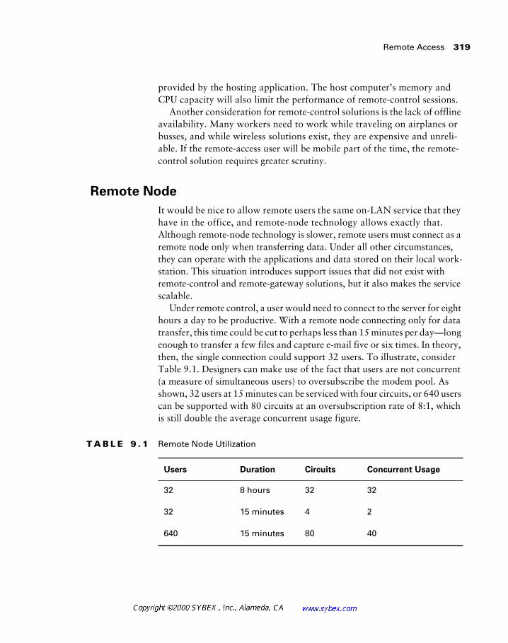
Remote Access 319
provided by the hosting application. The host computer’s memory and CPU capacity will also limit the performance of remote-control sessions.
Another consideration for remote-control solutions is the lack of offline availability. Many workers need to work while traveling on airplanes or busses, and while wireless solutions exist, they are expensive and unreli-able. If the remote-access user will be mobile part of the time, the remote-control solution requires greater scrutiny.
Remote Node
It would be nice to allow remote users the same on-LAN service that they have in the office, and remote-node technology allows exactly that. Although remote-node technology is slower, remote users must connect as a remote node only when transferring data. Under all other circumstances, they can operate with the applications and data stored on their local work-station. This situation introduces support issues that did not exist with remote-control and remote-gateway solutions, but it also makes the service scalable.
Under remote control, a user would need to connect to the server for eight hours a day to be productive. With a remote node connecting only for data transfer, this time could be cut to perhaps less than 15 minutes per day—long enough to transfer a few files and capture e-mail five or six times. In theory, then, the single connection could support 32 users. To illustrate, consider Table 9.1. Designers can make use of the fact that users are not concurrent (a measure of simultaneous users) to oversubscribe the modem pool. As shown, 32 users at 15 minutes can be serviced with four circuits, or 640 users can be supported with 80 circuits at an oversubscription rate of 8:1, which is still double the average concurrent usage figure.
T A B L E 9 . 1 Remote Node Utilization
Users Duration Circuits Concurrent Usage
32 8 hours 32 32
32 15 minutes 4 2
640 15 minutes 80 40
320 Chapter 9 � Remote Access Network Design
This clearly reduces the costs associated with remote access. Because the LAN connection is slow—the workstation thinks that the modem is a LAN adapter—applications and other static data should be stored locally.
Remote-node solutions are sometimes considered more secure than other remote-access methods, and Cisco supports this position. However, once a node connects, it is capable of running any software on the client worksta-tion, including hacking tools and other applications that may not adhere to corporate policy. Remote gateways, by serving a single function, and remote-control hosts, by placing applications under administrative control, may be more secure solutions.
Given the flexibility of remote-node solutions and the scalability afforded by them, most designers in modern remote solutions will opt for this solution first. If remote control is necessary, it can be combined with remote node by simply attaching to the remote-control host over the network session estab-lished as a node. This hybrid solution can provide the bandwidth savings sometimes available with remote control without making it the only connec-tion method.
Remote Users
So far, this chapter has merely touched upon remote users and their needs. However, it is important to expand upon their requirements. After all, the entire reason to deploy remote access is to provide services to users.
Remote users typically fall into one of three general categories:
� Occasional users, who may telecommute or need mobile access infrequently.
� Telecommuters, frequent users who telecommute from a fixed loca-tion. This would include small office/home office (SOHO) users with small LANs in their home.
� Mobile users, frequent users who travel a significant amount of time. This usage pattern often applies to the corporate sales force, some-times called “road warriors.”
Cisco recommends different hardware solutions for each of these catego-ries; however, all are predicated on the deployment of remote-node solu-tions. Let’s look at the various hardware solutions.
Remote Access 321
Low-Density Solutions
Cisco recommends the use of its 2509/2511 series routers for small user pools. This solution would address the needs of eight to 16 users and use external modems to provide a modem bank. Note that this solution is ana-log, which means that v.90/56k is not supported. This will limit users to 28.8 or 33.6Kbps.
Fixed-Location Solutions
Cisco positions its 760/770 ISDN router platform for the remote user oper-ating from a fixed location. This solution incorporates ISDN, which may significantly add to the access costs; however, it also provides greater band-width than a dial-up solution. As of this writing, it appears that Cisco is departing from the 760/770 platform in favor of newer 800 series systems. For actual deployments, designers should consult with their local Cisco representative.
One of the benefits to an ISDN-based SOHO solution is the use of a single line for voice and data. The installation may be configured to use both B channels (ISDN BRI) for data-only transmissions. A voice call can use either of the two channels, and this configuration will still provide data connectivity.
On the hosting side of ISDN connections, the designer has a number of options. Multiple ISDN BRI circuits may be terminated to Cisco’s 4000 series router. However, this solution would service only a few connections. Deployment of the 4000 or 7000 series routers with ISDN PRI connections could support a larger population of users. An alternative Cisco solution is the 3600 platform; however, this platform was unavailable when the current exam was developed.
Some recommendations in this book suggest using end-of-life or discontin-ued equipment. This is due to the age of the examination objectives and is reflective of the current examination. Please consult Cisco’s Web site for the most recent information.
High-Density Solutions
Cisco also offers the AS5200, which may be used for termination of ISDN and analog phone connections and can provide service for fixed-location
322 Chapter 9 � Remote Access Network Design
users. This platform yields the greatest flexibility of these solutions. Both the AS5100 (discontinued) and AS5200/AS5300/AS5800 products offer inte-grated modems, which may benefit administrators concerned with rack space. Integrated solutions typically benefit from lower total costs as well.
High-density solutions may also benefit large pools of mobile users. The smallest AS5200 configuration is typically 24 digital modems. Mobile user pools would not be served well with the 4000 or 7000 platform.
Both the 4000/4000M and 7000/7010 models are classified end-of-life at this writing. Please check the Cisco Web site for current information.
Network Design with DSL Technologies
Digital Subscriber Line (DSL) technologies were developed to be the “magic bullet” of the telecommunications industry. Primarily designed to add bandwidth to the home without installing fiber optics, the xDSL proto-cols have the potential to provide 52Mbps over already installed copper wire—a marked increase in performance. This feat is accomplished with spe-cial encoding of the digital signal. At present, DSL technologies are being used as a replacement for ISDN and analog ISP connections. However, as DSL technologies are accepted into the home and office, it is likely that they will be used for primary and backup data transfer and for high-demand ser-vices such as live video.
DSL technologies and cable modems are not included as an exam objective at present. This section is provided only as optional material for those readers interested in this technology.
The various DSL technologies, referred to in the generic as xDSL, provide for varying amounts of upstream and downstream bandwidth based on the equipment in use and the distances between that equipment. As a result of its distance sensitivity, xDSL typically must terminate within three miles of the central office, but access technologies may be employed to extend the range. Access products connect a remote termination device to the central office via
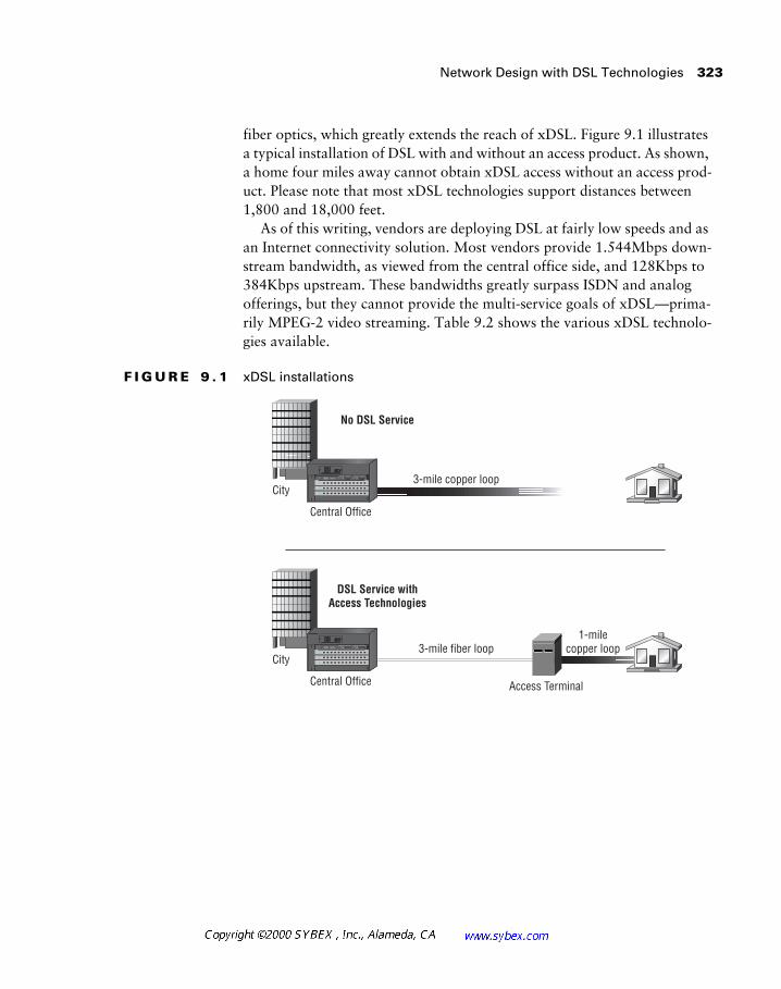
Network Design with DSL Technologies 323
fiber optics, which greatly extends the reach of xDSL. Figure 9.1 illustrates a typical installation of DSL with and without an access product. As shown, a home four miles away cannot obtain xDSL access without an access prod-uct. Please note that most xDSL technologies support distances between 1,800 and 18,000 feet.
As of this writing, vendors are deploying DSL at fairly low speeds and as an Internet connectivity solution. Most vendors provide 1.544Mbps down-stream bandwidth, as viewed from the central office side, and 128Kbps to 384Kbps upstream. These bandwidths greatly surpass ISDN and analog offerings, but they cannot provide the multi-service goals of xDSL—prima-rily MPEG-2 video streaming. Table 9.2 shows the various xDSL technolo-gies available.
F I G U R E 9 . 1 xDSL installations
City
City
Central Office
3-mile copper loop
1-milecopper loop
No DSL Service
Central Office Access Terminal
3-mile fiber loop
DSL Service withAccess Technologies
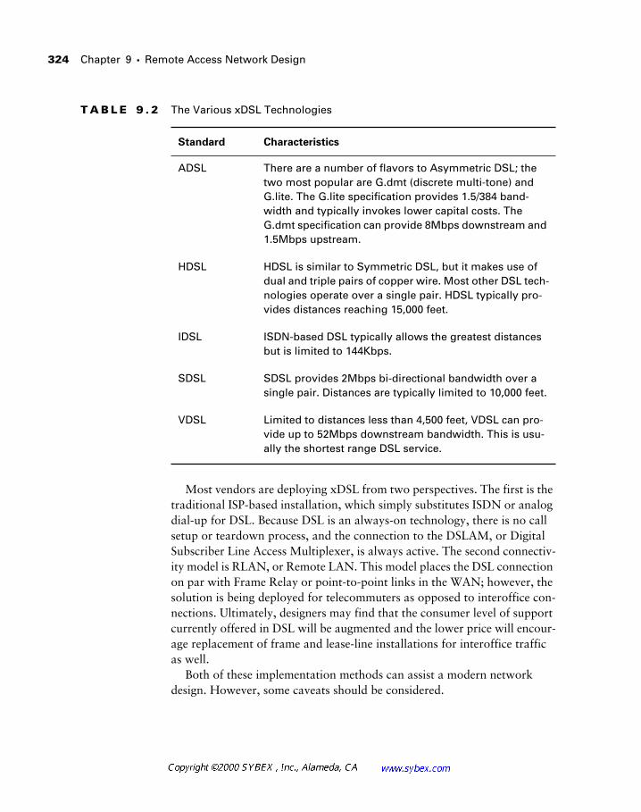
324
Chapter 9 �
Remote Access Network Design
Most vendors are deploying xDSL from two perspectives. The first is the traditional ISP-based installation, which simply substitutes ISDN or analog dial-up for DSL. Because DSL is an always-on technology, there is no call setup or teardown process, and the connection to the DSLAM, or Digital Subscriber Line Access Multiplexer, is always active. The second connectiv-ity model is RLAN, or Remote LAN. This model places the DSL connection on par with Frame Relay or point-to-point links in the WAN; however, the solution is being deployed for telecommuters as opposed to interoffice con-nections. Ultimately, designers may find that the consumer level of support currently offered in DSL will be augmented and the lower price will encour-age replacement of frame and lease-line installations for interoffice traffic as well.
Both of these implementation methods can assist a modern network design. However, some caveats should be considered.
T A B L E 9 . 2
The Various xDSL Technologies
Standard Characteristics
ADSL There are a number of flavors to Asymmetric DSL; the two most popular are G.dmt (discrete multi-tone) and G.lite. The G.lite specification provides 1.5/384 band-width and typically invokes lower capital costs. The G.dmt specification can provide 8Mbps downstream and 1.5Mbps upstream.
HDSL HDSL is similar to Symmetric DSL, but it makes use of dual and triple pairs of copper wire. Most other DSL tech-nologies operate over a single pair. HDSL typically pro-vides distances reaching 15,000 feet.
IDSL ISDN-based DSL typically allows the greatest distances but is limited to 144Kbps.
SDSL SDSL provides 2Mbps bi-directional bandwidth over a single pair. Distances are typically limited to 10,000 feet.
VDSL Limited to distances less than 4,500 feet, VDSL can pro-vide up to 52Mbps downstream bandwidth. This is usu-ally the shortest range DSL service.
Network Design with DSL Technologies 325
At present, most DSL vendors offer a single PVC with DSL installations. This limits connectivity options and makes redundancy difficult. A second PVC could provide a link to another head-end (distribution layer aggrega-tion point), and most vendors have multiple DSLAMs in the central office. An SVC-based solution would also assist in designing fault-tolerance.
Another concern with current DSL installations is that most products do not offer security solutions. The RLAN model greatly reduces this risk because the links are isolated at Layer 2, but all connectivity must be pro-vided by the head-end. This includes Internet connectivity. For Internet connections to an ISP, the risk is significantly greater, especially when con-sidering the bandwidth available for an attack and the use of static IP addresses or address pools. A number of significant attacks have already occurred as a result of these issues, and while they should not deter the use of the technology, the risks should be addressed with firewall technology.
A third consideration in DSL is the installation delay compared to other technologies. Vendors are moving towards splitterless hardware so that the telephone company does not have to install a splitter in the home. The split-ter divides the traditional phone signals from the data stream and provides a jack for standard telephones—DSL transports data and voice over the same twisted-pair wiring used for standard analog phone service. At present, installations require weeks to complete in order to validate the circuit to the home and install the splitter.
Cable Modems
It would be unfair to present the DSL technologies without providing some space for cable modems. Cable modems operate over the same cable system that provides television services using the same coax cable that is already used in the home. Most installations will provide two cables, one for the tele-vision and one for the data converter, but the signaling and system are the same. This is accomplished by allocating a television channel to data ser-vices. Bandwidth varies with the installation; however, 2Mbps in each direc-tion is not uncommon.
Detractors of cable modem technology are quick to point out that these installations are shared bandwidth, similar to Ethernet, which results in con-tention for the wire among neighbors. This design also introduces a security risk in that network analysis is possible, although vendors are working to address this concern. This issue does not exist in DSL, as the local loop con-nection to the home is switched. Traffic is not integrated until it reaches the
326 Chapter 9 � Remote Access Network Design
central office, and the switch will only forward traffic destined for the end station based on the MAC address. Cable modems are a shared technol-ogy—similar to 802.2 Ethernet versus 10-Base-T. Along the same lines, a cable modem is really a broadband Ethernet bridge.
Network designers may wish to consider cable modems as part of a VPN deployment, as the technology will not lend itself to the RLAN-type (Remote LAN-type) designs availed in DSL. Recall that an RLAN requires Layer 2 isolation—a service not offered by cable modem providers at present. This may change in the future if channels can be isolated to specific users. This may be especially true in very remote rural areas, where cable is available and DSL is not.
Summary
Remote connectivity has become increasingly important in modern networks as various organizations expand their requirements. These require-ments frequently include the need for data to be available at locations out-side of the traditional corporate office. Such sites may include retail sales outlets, employee homes, hotel rooms, and customer locations.
This chapter presented two of the more traditional remote-access technol-ogies—ISDN and X.25. Both have been used heavily to provide point-of-sale access to corporate data, including credit card verification and inventory sys-tems. While deployments are waning in the shadow of low-speed, low-cost Frame Relay and xDSL solutions, designers and administrators will have to work with these older technologies for the foreseeable future.
In addition to the specific remote-access technologies incorporated into the exam objectives, this chapter also addressed the various design models for providing remote connectivity to telecommuters and other remote staff. These included:
� Remote gateway
� Remote control
� Remote node
The chapter also discussed some of the needs frequently addressed in remote access solutions and the technology Cisco recommends to meet these challenges.
Review Questions 327
Review Questions
1. A remote gateway:
A. Provides access to a single application or service
B. Provides access to a display-only connection
C. Places the remote workstation on a slower extension of the LAN
D. None of the above
2. Remote-control solutions:
A. Are very limited because they allow access to only one application
B. Are very limited because there must be a connection in order to access applications and data
C. Cannot be used for remote access
D. Always consume more bandwidth than other remote-access solutions
3. Deployment of remote node systems:
A. Is extremely costly and serves a single function, which impacts scalability
B. Allows administrators to control all applications at a central source
C. Requires the use of fixed locations for remote users
D. Provides an effective connection to the LAN, although it is usually slower
4. The designer needs to provide 10 remote users with dial-in access. Cisco recommends that this design use:
A. The 2500 series platform with internal modems
B. The 2500 series platform with external modems
C. The 760 series router
D. The 7000 series router with the AS5200 modem bank
328 Chapter 9 � Remote Access Network Design
5. Because of billing and low-bandwidth factors, designers should incor-porate which of the following into their X.25 designs?
A. Full-mesh configurations
B. PVC installations only
C. Traffic filters and static routes
D. Traffic filters only, as static routes are not available in Cisco’s X.25 implementation
6. Which of the following is not true regarding X.25?
A. Provides high reliability
B. Provides high bandwidth
C. Cannot provide DCE functionality
D. Cannot provide DTE functionality
7. The X.25 protocol relates to which layer of the OSI model?
A. Application
B. Session
C. Data link
D. Network
8. True or false: A Cisco router cannot provide X.25 switching services.
A. True
B. False
9. Which of the following is not an encryption technology for tunnels on ISDN?
A. L2F
B. CDP
C. PPTP
D. L2TP

Review Questions 329
10. ISDN PRI provides which of the following?
A. Two B channels and one D channel for a total of 144Kbps
B. 23 B channels and one D channel on a T1
C. 24 B channels on a T1
D. 12 B channels for data and 12 B channels for voice on a T1
11. A service that provides a LAN-equivalent, albeit slower, connection to the corporate network is called:
A. Remote gateway
B. Remote control
C. Remote network
D. Remote node
12. The network architect does not wish to deploy a full-mesh X.25 net-work. The best solution would be to do which of the following?
A. Select another protocol, as X.25 must be configured in a full mesh.
B. Use subinterfaces.
C. Use the X.121 specification.
D. Use the LAPB protocol and tunnel X.25 in PPP.
13. Cable modems are most similar to which of the following technologies?
A. X.25
B. Frame Relay
C. ATM
D. Ethernet
14. True or false: MMP is an open standard.
A. True
B. False
330 Chapter 9 � Remote Access Network Design
15. A benefit of ISDN in the home office is:
A. Greater bandwidth than any other technology
B. Low cost
C. Data and voice services on the same BRI
D. Always-on service
16. A dial-in server that provides access to the company’s e-mail system is typically part of:
A. A remote-node solution
B. A remote-control solution
C. A remote-gateway solution
17. Multilink Multichassis PPP operates:
A. Between two devices, connecting a single BRI circuit between them
B. Between a single remote device and two local devices, terminating a data channel on one server and a control channel on the other
C. Across multiple routers and access servers
D. With ISDN PRI only
18. Compared to Frame Relay, X.25 has:
A. Higher latency
B. Higher bandwidth
C. Less overhead
D. Less international support
19. True or false: Both Frame Relay and X.25 support subinterfaces.
A. True
B. False

Review Questions 331
20. ISDN BRI provides how much B channel bandwidth for the user?
A. 64Kbps
B. 128Kbps
C. 144Kbps
D. 1.544Mbps

332 Chapter 9 � Remote Access Network Design
Answers to Review Questions
1. A.
2. B.
3. D.
4. B.
5. C.
6. B.
7. D.
8. B.
9. B.
10. B.
11. D.
12. B.
13. D.
14. B.
15. C.
16. C.
17. C.
18. A.
19. A.
20. B.
Chapter
10Designing for Mainframe Connectivity
CISCO INTERNETWORK DESIGN EXAM OBJECTIVES COVERED IN THIS CHAPTER:
� Discuss the hierarchical and connection-oriented nature
of SNA.
� Describe the use of gateways to attach Token Ring devices to
an SNA network.
� Explain how LLC2 and SDLC sessions are established.
� Describe reasons for integrating SNA technology with
internetworking technology.
� Examine a client’s requirements and recommend SNA
internetworking solutions.
� Construct SNA designs that replace legacy communications
equipment with multiprotocol routers.
� Build redundancy into SNA internetworks.
� Design remote source-route bridged SNA internetworks in full-
and partial-mesh configurations.
� Choose the appropriate place to do priority queuing or custom
queuing for SNA.
One can easily imagine the mainframe sharing a line from author Samuel Clemens (Mark Twain)—“The report of my death was an exaggeration.” For years, experts predicted the demise of the heavy iron, and while servers have definitely impacted sales of these traditional necessities, it is clear that mainframes will exist in modern networks for some time.
The mainframe was initially designed to be a central processing point in the corporation, sharing resources with hundreds of users on dumb termi-nals—workstations that could not function without a host. This chapter will focus more on SNA and the evolution from front-end processors and cluster controllers to 3270 terminal emulators than on the mechanics of dumb ter-minals and the intricacies of the protocol itself. This includes the integration of the mainframe into the modern network design.
Mainframe Overview
It’s best to begin at the beginning, and in mainframe networks that requires an understanding of the traditional dumb-terminal configuration and the protocols that were, and still are, used.
As shown in Figure 10.1, traditional mainframe networks typically incor-porate four basic components. These include the host, a front-end processor (FEP), a cluster controller, and dumb terminals. Such installations commu-nicate using SNA. The FEP is responsible for handling all user communica-tions, which frees the host for processing. Under this configuration, the FEP runs the Network Control Program (NCP) and the host typically runs the Virtual Telecommunications Access Method (VTAM) program.
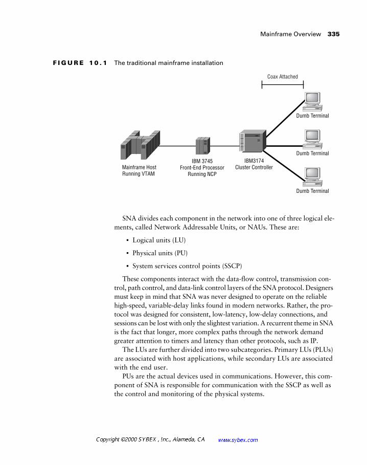
Mainframe Overview 335
F I G U R E 1 0 . 1 The traditional mainframe installation
SNA divides each component in the network into one of three logical ele-ments, called Network Addressable Units, or NAUs. These are:
� Logical units (LU)
� Physical units (PU)
� System services control points (SSCP)
These components interact with the data-flow control, transmission con-trol, path control, and data-link control layers of the SNA protocol. Designers must keep in mind that SNA was never designed to operate on the reliable high-speed, variable-delay links found in modern networks. Rather, the pro-tocol was designed for consistent, low-latency, low-delay connections, and sessions can be lost with only the slightest variation. A recurrent theme in SNA is the fact that longer, more complex paths through the network demand greater attention to timers and latency than other protocols, such as IP.
The LUs are further divided into two subcategories. Primary LUs (PLUs) are associated with host applications, while secondary LUs are associated with the end user.
PUs are the actual devices used in communications. However, this com-ponent of SNA is responsible for communication with the SSCP as well as the control and monitoring of the physical systems.
Coax Attached
IBM3174Cluster Controller
IBM 3745Front-End Processor
Running NCPMainframe HostRunning VTAM
Dumb Terminal
Dumb Terminal
Dumb Terminal
336
Chapter 10 �
Designing for Mainframe Connectivity
The SSCP is part of the VTAM program on the host system. It is respon-sible for controlling all sessions with the mainframe. These sessions may be divided into domains, creating logical groupings of devices.
SNA is generally considered a hierarchical networking technology. This is more due to the control placed on the domain by the host than the physical and logical design of the topology. The host computer, which is usually the mainframe, groups PLUs and the various host systems. These systems are usually referred to by their individual names, including CICS (Customer Information Control System) and TSO—which are both applications that run in regions on the mainframe. VTAM and SSCP are found at a lower layer of the hierarchy—VTAM and SSCP map closer to an operating system than to applications. One of the benefits of mainframe systems is the isolation between different operations in the machine.
The physical layer of the mainframe is called the
channel
. This is typically an ESCON (Enterprise System Connect) connection; however, bus and tag is also used. ESCON connections operate at 17MBps (megabytes per second), which is greater than Fast Ethernet in the non-mainframe environment. While they are not as fast as the SuperHPPI (High Performance Parallel Inter-face, capable of 800 MBps) standard and other high-bandwidth technologies, designers must keep in mind that ESCON connections are very efficient and that mainframe data typically involves very small, 2-thousand-byte trans-fers. While large file transfers do occur, they usually use tape and other high-capacity media.
The FEP is a Type 4 node in SNA, contrasted with the Type 5 designation given the host. This function is typically provided with a 3745 communica-tion controller, which can connect to the network via a Token Ring adapter, or TIC (Token Ring interface coupler). The Type 4 device connects to clus-ter controllers (devices that provide sessions to dumb terminals) or logical units via SDLC or Token Ring. Ultimately, connections are established between two logical units, which require connections to be established between the SSCP-LU and SSCP-PU. The LU is a logical unit, whereas the PU is a physical unit.
Over its evolution, mainframe access has changed substantially from the dumb terminal (3270) and cluster controller days. Gateways once provided the connections between PCs and the mainframe, allowing corporations to remove the dumb terminals from the desktop. As this technology evolved, companies began providing gateway services through Web browsers to reduce the costs and maintenance associated with client installations. The mainframe administrator would create a sysgen, or system generation
Mainframe Overview 337
macro. This defined the Token Ring gateway as a switched major node. Depending on the configuration, the gateway could be configured as a PU Type 2 device or as an LU.
In addition, software and hardware for the PC also allowed the elimina-tion of the gateway—the PC could directly connect to the host. While this added administration tasks for the administrator, it also improved the per-formance of the 3270 connection—the gateway and the necessary conver-sions were no longer a bottleneck. This solution was better suited for advanced users with a demand for more complex services than the gateway and thin-client approach. Many companies (who have not converted to TCP/IP-based hosts) still provide gateway services, which are a suitable compro-mise for the majority of users, providing reasonable performance with sim-plified client administration.
As SNA evolved, numerous protocols have been developed to transport it across modern networks. These technologies include SDLC tunneling (STUN, or serial tunneling), remote source-route bridging, data-link switching, and SDLC-to-LLC2 conversions. LLC2 stands for Logical Link Control, version 2, and is a common framing transport. In addition, Cisco has announced a new technology—SNASw (Systems Network Architecture Switching Services). This continuing development toward support for SNA is a likely indication that the protocol will remain significant in the near term.
It is important to remember that SNA is not a routable protocol (OSI defini-tion), even though the term “SNA routing” is scattered throughout this text and the IBM documentation. Through the use of the Routing Information Field and other techniques, the source station can control the bridged paths used by Token Ring.
The Routing Information Field
The Routing Information Field, or RIF, is a Token Ring-specific function that allows the workstation to find a single path through the bridged net-work. You may recall from previous texts that there are numerous types of bridging, the most common of which is transparent bridging. Transparent bridging relies on each bridge to maintain a table showing which MAC addresses are available for each interface.
338 Chapter 10 � Designing for Mainframe Connectivity
Token Ring frames provide for a field to store the path information—removing the need for the bridges in the network to store this information. Workstations (or other source devices) begin sessions by sending an explorer packet into the network. This packet is flooded throughout the network, and each bridge will append routing information to the RIF of the packet. The first packet received by the destination will be returned with the populated RIF—providing step-by-step instructions for future packets. This mecha-nism not only provides for routing in a bridged environment, but also can provide limited load balancing because the first packet received likely took the shortest path with the least delay.
One of the negatives of source-route bridging is the mechanism that pop-ulates the RIF. This is provided by the explorer packet, which is the flood referred to in the previous paragraph. This packet is replicated to traverse every ring in the network for each new connection between two stations. On a large network, this may result in a substantial amount of multicast traffic, and many designers rely on proxy services to populate the RIF without the need to flood the network. Proxy explorer functions are provided on Cisco routers and operate by remembering previous RIF information—the first connection to a station still floods, but all subsequent connections from that ring can use the proxy information to provide the route.
The RIF is stored in the format ring-bridge-ring, where each ring and bridge is assigned a unique number. These numbers can augment trouble-shooting since the administrator can look at the RIF to help find the trou-blesome component.
It is important to note that Ethernet and other protocols do not support the concept of a RIF. When transiting these topologies, the network will either encapsulate the frame or rely on transparent bridging.
Network Design with SDLC Tunneling
SDLC tunneling (STUN) provides for the encapsulation of SNA traf-fic in three different configurations. The first is called serial direct, wherein the serial ports on the router are directly connected to local controllers. The controllers then connect to terminals. The other two configurations, HDLC and TCP/IP, are considerably more advanced than serial direct.
HDLC (High-Level Data Link Control) encapsulation is used between routers and offers the best performance for traffic over a serial connection.
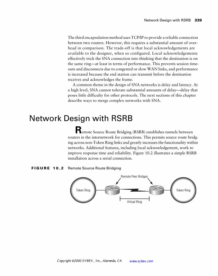
Network Design with RSRB 339
The third encapsulation method uses TCP/IP to provide a reliable connection between two routers. However, this requires a substantial amount of over-head in comparison. The trade-off is that local acknowledgements are available to the designer, when so configured. Local acknowledgements effectively trick the SNA connection into thinking that the destination is on the same ring—at least in terms of performance. This prevents session time-outs and disconnects due to congested or slow WAN links, and performance is increased because the end station can transmit before the destination receives and acknowledges the frame.
A common theme in the design of SNA networks is delay and latency. At a high level, SNA cannot tolerate substantial amounts of delay—delay that poses little difficulty for other protocols. The next sections of this chapter describe ways to merge complex networks with SNA.
Network Design with RSRB
Remote Source Route Bridging (RSRB) establishes tunnels between routers in the internetwork for connections. This permits source route bridg-ing across non-Token Ring links and greatly increases the functionality within networks. Additional features, including local acknowledgement, work to improve response time and reliability. Figure 10.2 illustrates a simple RSRB installation across a serial connection.
F I G U R E 1 0 . 2 Remote Source Route Bridging
Remote Peer Bridges
Virtual Ring
Token RingToken Ring
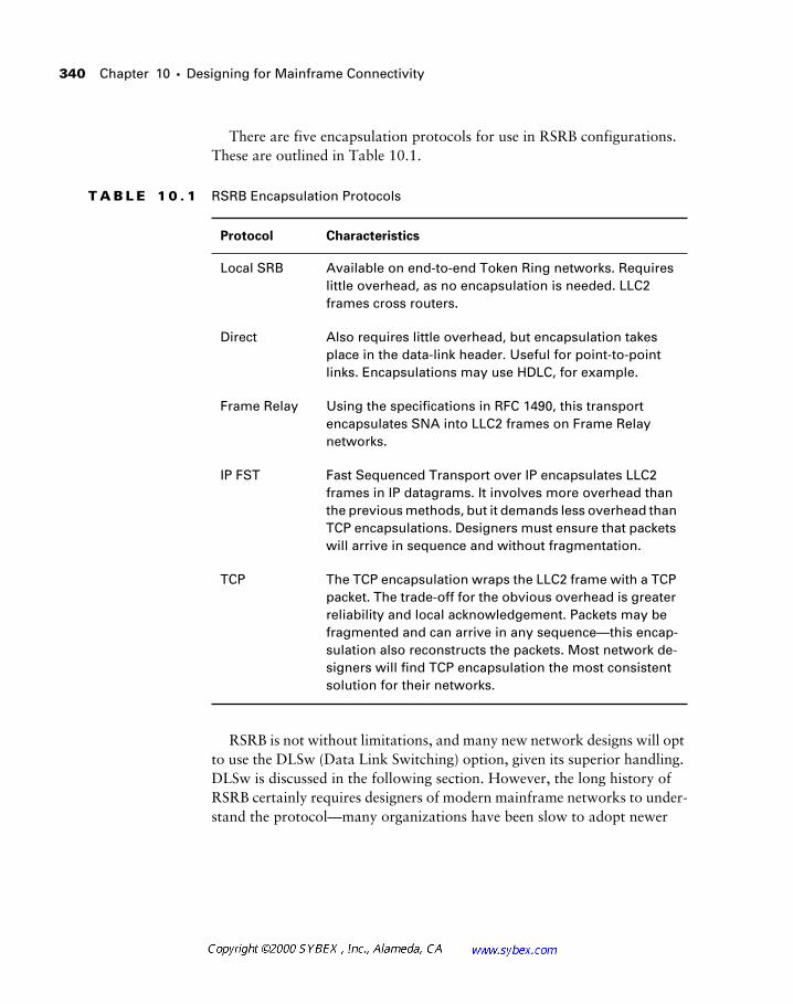
340
Chapter 10 �
Designing for Mainframe Connectivity
There are five encapsulation protocols for use in RSRB configurations. These are outlined in Table 10.1.
RSRB is not without limitations, and many new network designs will opt to use the DLSw (Data Link Switching) option, given its superior handling. DLSw is discussed in the following section. However, the long history of RSRB certainly requires designers of modern mainframe networks to under-stand the protocol—many organizations have been slow to adopt newer
T A B L E 1 0 . 1
RSRB Encapsulation Protocols
Protocol Characteristics
Local SRB Available on end-to-end Token Ring networks. Requires little overhead, as no encapsulation is needed. LLC2 frames cross routers.
Direct Also requires little overhead, but encapsulation takes place in the data-link header. Useful for point-to-point links. Encapsulations may use HDLC, for example.
Frame Relay Using the specifications in RFC 1490, this transport encapsulates SNA into LLC2 frames on Frame Relay networks.
IP FST Fast Sequenced Transport over IP encapsulates LLC2 frames in IP datagrams. It involves more overhead than the previous methods, but it demands less overhead than TCP encapsulations. Designers must ensure that packets will arrive in sequence and without fragmentation.
TCP The TCP encapsulation wraps the LLC2 frame with a TCP packet. The trade-off for the obvious overhead is greater reliability and local acknowledgement. Packets may be fragmented and can arrive in any sequence—this encap-sulation also reconstructs the packets. Most network de-signers will find TCP encapsulation the most consistent solution for their networks.
Network Design with DLSw 341
methodologies because of the lack of perceived benefits that come with upgrading and the required training and support demands. In the context of most organizations, which appear to be moving away from SNA, the strate-gic benefits of changing are dubious at best.
The steps to configure RSRB differ slightly for each encapsulation type; however, the primary steps are similar. A sample configuration for TCP encapsulation is shown in the following output. Note that the virtual ring is given the number 406 and has two remote peers and that the Marketing Seg-ment on Token Ring 4/0 is linked to the virtual ring via the source-bridge command.
source-bridge ring-group 406
source-bridge remote-peer 406 tcp 10.100.105.254
source-bridge remote-peer 406 tcp 10.1.1.1
interface TokenRing4/0
description Marketing Segment
ip address 192.168.19.1 255.255.255.0
no ip directed-broadcast
no keepalive
early-token-release
ring-speed 16
source-bridge 226 3 406
source-bridge spanning
source-bridge proxy-explorer
Network Design with DLSw
DLSw was developed to address some of the shortcomings in RSRB, and it is gaining popularity, but many organizations are resisting a changeover. This was likely the result of Year 2000 preparations and other new deployments that demand resources from organizations. In the con-text of network design, an entire chapter could be written regarding the proper installation and configuration of DLSw. However, for the purposes of the exam objectives, readers should be concerned only with a high-level understanding of the protocol itself. Consult RFC 1795 for additional information.
342 Chapter 10 � Designing for Mainframe Connectivity
DLSw provides many features to the network designer. These include:
� Supports LLC2 termination, which eliminates the need for keepalives to cross WAN links. This feature provides functionality similar to local acknowledgement and also avoids timeouts, which are a signifi-cant concern to designers with the time-sensitive SNA protocol. The local router acknowledges frames.
� Supports SNA traffic over TCP, which adds reliability to the transport across WAN links.
� Supports NetBIOS over TCP; however, few implementations use this function.
� Provides for termination of the RIF (Routing Information Field). In RSRB, the RIF is incorporated into the WAN cloud. This feature limits SRB to seven hops. In DLSw, the RIF field is terminated in a virtual ring, which is the connection between two DLSw peer routers. This permits 13-hop installations; however, administrators should be cau-tioned that the RIF will be incomplete for troubleshooting. The great-est benefit to this feature is that explorer packets are contained on each side of the cloud, reducing traffic and preserving bandwidth.
� Permits load balancing and allows for backup peer routers.
� Is an open standard, and as such, it allows designers to interconnect different router brands.
In addition, Cisco offers enhanced DLSw features (referred to as DLSw+), including:
� Peer groups
� Border and on-demand peers
� Backward compatibility with STUN and RSRB
Of these enhanced features, designers may find backward compatibility useful in migrations from STUN or RSRB to DLSw, which is generally regarded as the superior methodology. Peer groups can also assist the design. Routers within a peer group work to permit “any-to-any” connectivity, but peer groups also can simplify configuration and optimize explorer packet processing.
Peer routers also can provide the designer with load balancing. When con-figured, the router will use a round-robin method to balance sessions on a
Redundancy as a Design Consideration 343
connection basis. This requires equal-cost paths. If load balancing is not enabled, the router will use a single preferred path for all explorer packets.
The following output provides a sample DLSw configuration, where the ring group has been defined and the router has been configured as a local peer in the group. This configuration uses its loopback address in order to circumvent interface failures.
source-bridge ring-group 9
dlsw local-peer peer-id 10.12.24.1 (loopback)
dlsw remote-peer 0 tcp 10.14.10.1
dlsw remote-peer 0 tcp 10.10.18.1
dlsw bridge-group 9
It is very unlikely that the loopback interface will fail—unlike the physical inter-faces. (Cisco defines the loopback as never failing, but sometimes an admin-istrator will inadvertently delete the interface or remove its address.) Use of the loopback can greatly enhance the reliability and supportability of the router. The loopback notation in the previous output reflects the IP address of the router’s loopback interface—LO0. This is administratively assigned, as opposed to the traditional IP loopback of 127.0.0.1.
Redundancy as a Design Consideration
The critical nature of mainframes in modern networks mandates the use of redundant links for connectivity. In IP-based mainframe installations, this function frequently incorporates the use of VIPA, or virtual IP addressing. In SNA environments, other techniques are used.
One of the most fundamental redundancy techniques in SNA designs is to install dual front-end processors (FEP). Given the critical nature of the FEP in the network, this is a reasonable precaution.
When dual FEPs are configured, they use the same locally administered address (LAA). The client, when sending an explorer packet, will connect to the first FEP that responds via the RIF.
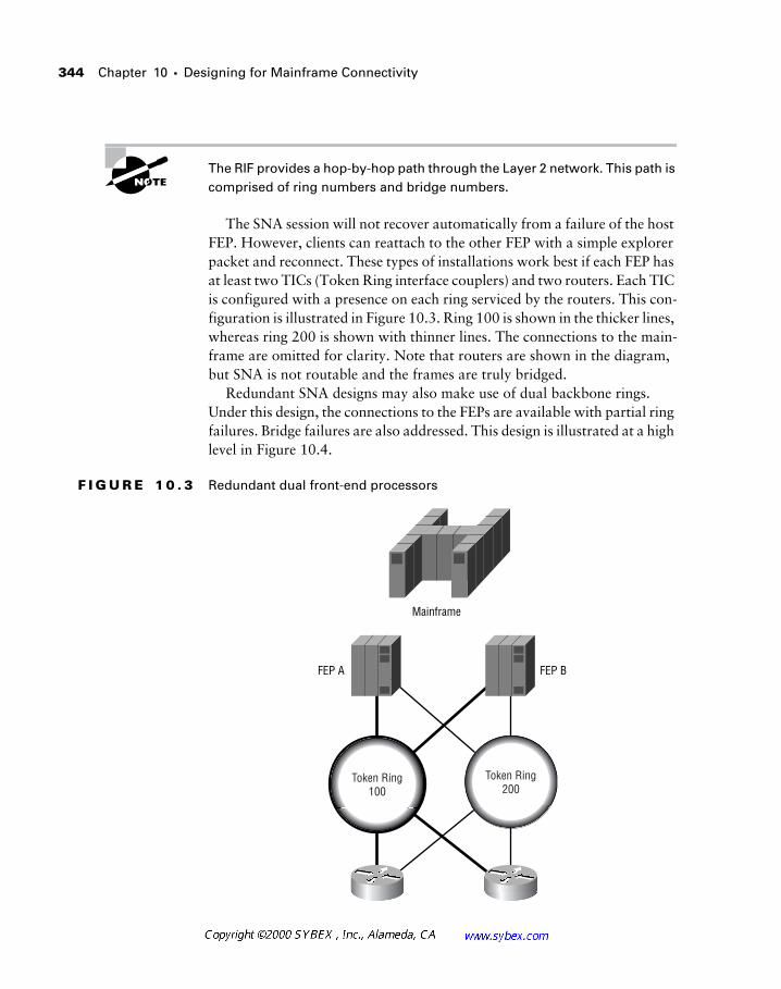
344 Chapter 10 � Designing for Mainframe Connectivity
The RIF provides a hop-by-hop path through the Layer 2 network. This path is comprised of ring numbers and bridge numbers.
The SNA session will not recover automatically from a failure of the host FEP. However, clients can reattach to the other FEP with a simple explorer packet and reconnect. These types of installations work best if each FEP has at least two TICs (Token Ring interface couplers) and two routers. Each TIC is configured with a presence on each ring serviced by the routers. This con-figuration is illustrated in Figure 10.3. Ring 100 is shown in the thicker lines, whereas ring 200 is shown with thinner lines. The connections to the main-frame are omitted for clarity. Note that routers are shown in the diagram, but SNA is not routable and the frames are truly bridged.
Redundant SNA designs may also make use of dual backbone rings. Under this design, the connections to the FEPs are available with partial ring failures. Bridge failures are also addressed. This design is illustrated at a high level in Figure 10.4.
F I G U R E 1 0 . 3 Redundant dual front-end processors
FEP A FEP B
Mainframe
Token Ring200
Token Ring100
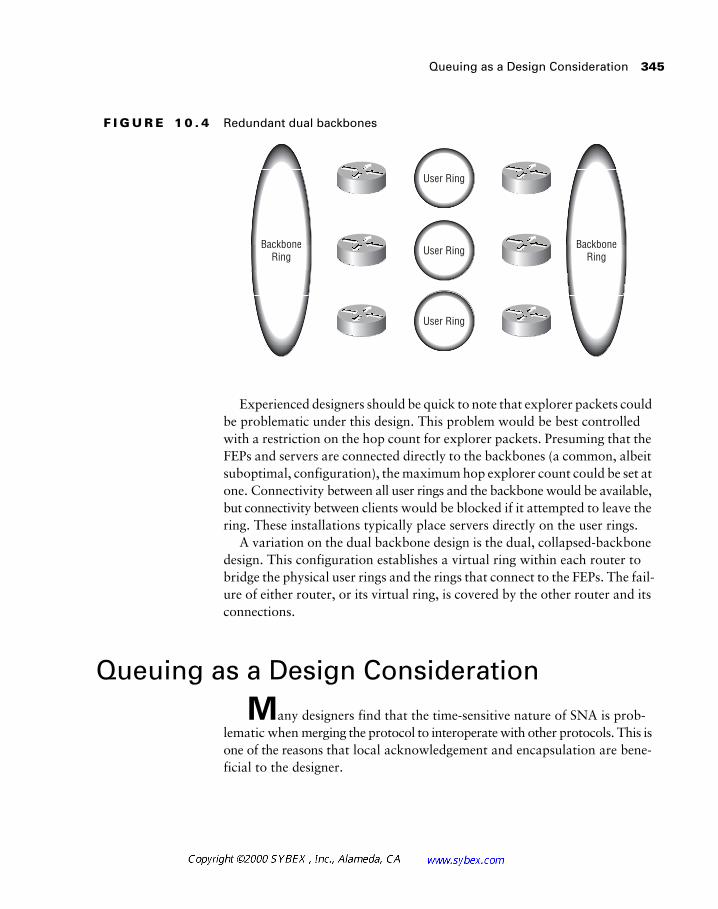
Queuing as a Design Consideration 345
F I G U R E 1 0 . 4 Redundant dual backbones
Experienced designers should be quick to note that explorer packets could be problematic under this design. This problem would be best controlled with a restriction on the hop count for explorer packets. Presuming that the FEPs and servers are connected directly to the backbones (a common, albeit suboptimal, configuration), the maximum hop explorer count could be set at one. Connectivity between all user rings and the backbone would be available, but connectivity between clients would be blocked if it attempted to leave the ring. These installations typically place servers directly on the user rings.
A variation on the dual backbone design is the dual, collapsed-backbone design. This configuration establishes a virtual ring within each router to bridge the physical user rings and the rings that connect to the FEPs. The fail-ure of either router, or its virtual ring, is covered by the other router and its connections.
Queuing as a Design Consideration
Many designers find that the time-sensitive nature of SNA is prob-lematic when merging the protocol to interoperate with other protocols. This is one of the reasons that local acknowledgement and encapsulation are bene-ficial to the designer.
User Ring
User RingBackboneRing
BackboneRing
User Ring
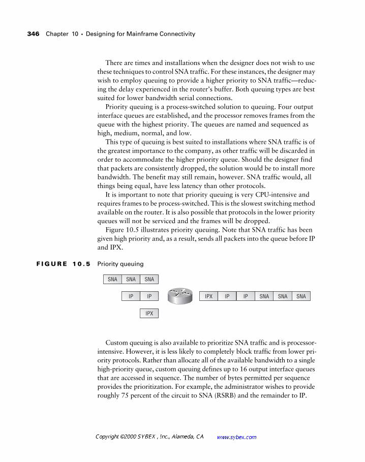
346 Chapter 10 � Designing for Mainframe Connectivity
There are times and installations when the designer does not wish to use these techniques to control SNA traffic. For these instances, the designer may wish to employ queuing to provide a higher priority to SNA traffic—reduc-ing the delay experienced in the router’s buffer. Both queuing types are best suited for lower bandwidth serial connections.
Priority queuing is a process-switched solution to queuing. Four output interface queues are established, and the processor removes frames from the queue with the highest priority. The queues are named and sequenced as high, medium, normal, and low.
This type of queuing is best suited to installations where SNA traffic is of the greatest importance to the company, as other traffic will be discarded in order to accommodate the higher priority queue. Should the designer find that packets are consistently dropped, the solution would be to install more bandwidth. The benefit may still remain, however. SNA traffic would, all things being equal, have less latency than other protocols.
It is important to note that priority queuing is very CPU-intensive and requires frames to be process-switched. This is the slowest switching method available on the router. It is also possible that protocols in the lower priority queues will not be serviced and the frames will be dropped.
Figure 10.5 illustrates priority queuing. Note that SNA traffic has been given high priority and, as a result, sends all packets into the queue before IP and IPX.
F I G U R E 1 0 . 5 Priority queuing
Custom queuing is also available to prioritize SNA traffic and is processor-intensive. However, it is less likely to completely block traffic from lower pri-ority protocols. Rather than allocate all of the available bandwidth to a single high-priority queue, custom queuing defines up to 16 output interface queues that are accessed in sequence. The number of bytes permitted per sequence provides the prioritization. For example, the administrator wishes to provide roughly 75 percent of the circuit to SNA (RSRB) and the remainder to IP.
SNA SNA SNA
SNA SNA SNAIP IP IPX IP IP
IPX
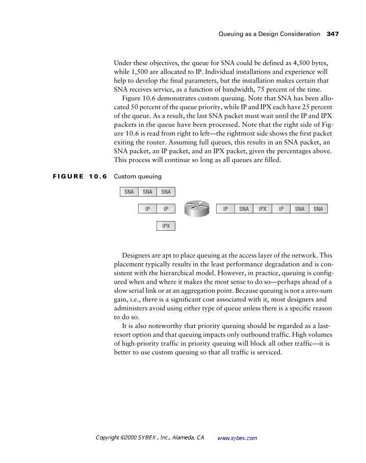
Queuing as a Design Consideration 347
Under these objectives, the queue for SNA could be defined as 4,500 bytes, while 1,500 are allocated to IP. Individual installations and experience will help to develop the final parameters, but the installation makes certain that SNA receives service, as a function of bandwidth, 75 percent of the time.
Figure 10.6 demonstrates custom queuing. Note that SNA has been allo-cated 50 percent of the queue priority, while IP and IPX each have 25 percent of the queue. As a result, the last SNA packet must wait until the IP and IPX packets in the queue have been processed. Note that the right side of Fig-ure 10.6 is read from right to left—the rightmost side shows the first packet exiting the router. Assuming full queues, this results in an SNA packet, an SNA packet, an IP packet, and an IPX packet, given the percentages above. This process will continue so long as all queues are filled.
F I G U R E 1 0 . 6 Custom queuing
Designers are apt to place queuing at the access layer of the network. This placement typically results in the least performance degradation and is con-sistent with the hierarchical model. However, in practice, queuing is config-ured when and where it makes the most sense to do so—perhaps ahead of a slow serial link or at an aggregation point. Because queuing is not a zero-sum gain, i.e., there is a significant cost associated with it, most designers and administers avoid using either type of queue unless there is a specific reason to do so.
It is also noteworthy that priority queuing should be regarded as a last-resort option and that queuing impacts only outbound traffic. High volumes of high-priority traffic in priority queuing will block all other traffic—it is better to use custom queuing so that all traffic is serviced.
SNA SNA SNA
IP SNA SNAIP IP IP SNA IPX
IPX
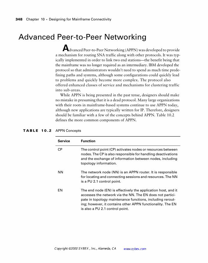
348 Chapter 10 � Designing for Mainframe Connectivity
Advanced Peer-to-Peer Networking
Advanced Peer-to-Peer Networking (APPN) was developed to provide a mechanism for routing SNA traffic along with other protocols. It was typ-ically implemented in order to link two end stations—the benefit being that the mainframe was no longer required as an intermediary. IBM developed the protocol so that administrators wouldn’t need to spend as much time prede-fining paths and systems, although some configurations could quickly lead to problems and quickly become more complex. The protocol also offered enhanced classes of service and mechanisms for clustering traffic into sub-areas.
While APPN is being presented in the past tense, designers should make no mistake in presuming that it is a dead protocol. Many large organizations with their roots in mainframe-based systems continue to use APPN today, although new applications are typically written for IP. Therefore, designers should be familiar with a few of the concepts behind APPN. Table 10.2 defines the more common components of APPN.
T A B L E 1 0 . 2 APPN Concepts
Service Function
CP The control point (CP) activates nodes or resources between nodes. The CP is also responsible for handling deactivations and the exchange of information between nodes, including topology information.
NN The network node (NN) is an APPN router. It is responsible for locating and connecting sessions and resources. The NN is a PU 2.1 control point.
EN The end node (EN) is effectively the application host, and it accesses the network via the NN. The EN does not partici-pate in topology maintenance functions, including rerout-ing; however, it contains other APPN functionality. The EN is also a PU 2.1 control point.
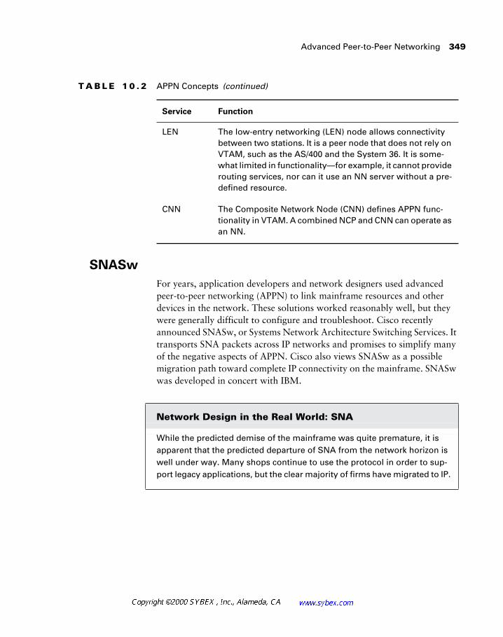
Advanced Peer-to-Peer Networking 349
SNASw
For years, application developers and network designers used advanced peer-to-peer networking (APPN) to link mainframe resources and other devices in the network. These solutions worked reasonably well, but they were generally difficult to configure and troubleshoot. Cisco recently announced SNASw, or Systems Network Architecture Switching Services. It transports SNA packets across IP networks and promises to simplify many of the negative aspects of APPN. Cisco also views SNASw as a possible migration path toward complete IP connectivity on the mainframe. SNASw was developed in concert with IBM.
LEN The low-entry networking (LEN) node allows connectivity between two stations. It is a peer node that does not rely on VTAM, such as the AS/400 and the System 36. It is some-what limited in functionality—for example, it cannot provide routing services, nor can it use an NN server without a pre-defined resource.
CNN The Composite Network Node (CNN) defines APPN func-tionality in VTAM. A combined NCP and CNN can operate as an NN.
Network Design in the Real World: SNA
While the predicted demise of the mainframe was quite premature, it is apparent that the predicted departure of SNA from the network horizon is well under way. Many shops continue to use the protocol in order to sup-port legacy applications, but the clear majority of firms have migrated to IP.
T A B L E 1 0 . 2 APPN Concepts (continued)
Service Function
350 Chapter 10 � Designing for Mainframe Connectivity
Summary
This chapter addressed many of the issues that involve mainframe con-nectivity in modern network design. These issues included an overview of the encapsulation methods available for SNA traffic and the frequent need for redundancy in these installations.
This chapter also addressed the common design criteria and options asso-ciated with mainframe installations and the SNA protocol, including:
� RSRB
� DLSw
� APPN
� Redundancy
� Queuing
Due to both the history of RSRB and its foundation in the other protocols, designers are encouraged to make certain that they feel comfortable with RSRB from a practical perspective as well as an exam perspective. Even in organizations that have migrated to newer protocols, the concepts embed-ded in RSRB offer a strong foundation for the designer and administrator.
One of the critical features in IP-based mainframe connectivity is redun-dancy. One option in this vein is VIPA, or virtual IP addressing. In a VIPA installation, a subnet is created within the host itself, and two distinct sub-nets are attached to the virtual subnet—typically via the Cisco Channel Interface Processor (CIP) and ESCON connections, which greatly improve the performance of the connection between the routed network and the mainframe. However, there are other options. VIPA provides for router, CIP, ESCON interface, and ESCON connection failures, as the virtual subnet is available via the alternative path. Note that the alternative path is not used just for backup—VIPA can facilitate load balancing as well.
Designers should plan for these implementations with care, noting that the mainframe IP stack typically does not support advanced or proprietary rout-ing protocols. Therefore, it is likely that static routes or RIP redistribution will be necessary on the router.
The router may also front-end TN3270 connections to the mainframe. This removes some of the processing overhead required for terminal access.
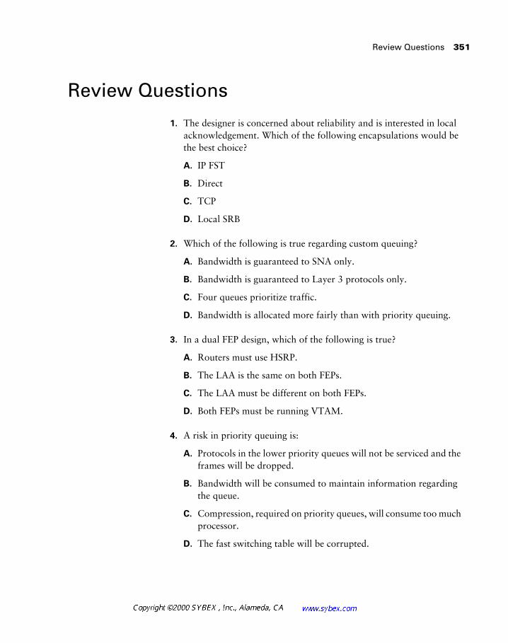
Review Questions 351
Review Questions
1. The designer is concerned about reliability and is interested in local acknowledgement. Which of the following encapsulations would be the best choice?
A. IP FST
B. Direct
C. TCP
D. Local SRB
2. Which of the following is true regarding custom queuing?
A. Bandwidth is guaranteed to SNA only.
B. Bandwidth is guaranteed to Layer 3 protocols only.
C. Four queues prioritize traffic.
D. Bandwidth is allocated more fairly than with priority queuing.
3. In a dual FEP design, which of the following is true?
A. Routers must use HSRP.
B. The LAA is the same on both FEPs.
C. The LAA must be different on both FEPs.
D. Both FEPs must be running VTAM.
4. A risk in priority queuing is:
A. Protocols in the lower priority queues will not be serviced and the frames will be dropped.
B. Bandwidth will be consumed to maintain information regarding the queue.
C. Compression, required on priority queues, will consume too much processor.
D. The fast switching table will be corrupted.
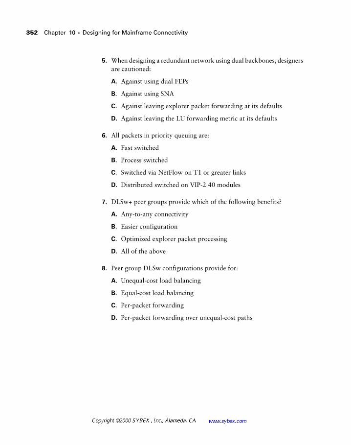
352 Chapter 10 � Designing for Mainframe Connectivity
5. When designing a redundant network using dual backbones, designers are cautioned:
A. Against using dual FEPs
B. Against using SNA
C. Against leaving explorer packet forwarding at its defaults
D. Against leaving the LU forwarding metric at its defaults
6. All packets in priority queuing are:
A. Fast switched
B. Process switched
C. Switched via NetFlow on T1 or greater links
D. Distributed switched on VIP-2 40 modules
7. DLSw+ peer groups provide which of the following benefits?
A. Any-to-any connectivity
B. Easier configuration
C. Optimized explorer packet processing
D. All of the above
8. Peer group DLSw configurations provide for:
A. Unequal-cost load balancing
B. Equal-cost load balancing
C. Per-packet forwarding
D. Per-packet forwarding over unequal-cost paths
Review Questions 353
9. STUN local acknowledgement provides which of the following benefits?
A. Prevention of application timeouts
B. Packet conversion
C. Compression
D. Encryption
10. An LAA is:
A. An SNA DLSw address
B. A locally administered IP address
C. A locally administered MAC address
D. Stored on the TIC only
11. True or false: Dual FEPs can use the same LAA.
A. True
B. False
12. True or false: The odds of packet loss are greater for lower priority packets with priority queuing than with custom queuing.
A. True
B. False
13. The RIF field:
A. Marks a frame as modified by DLSw
B. Marks a frame as discard eligible
C. Provides a hop-by-hop path through the bridged network
D. Provides a hop-by-hop path through the routed network

354 Chapter 10 � Designing for Mainframe Connectivity
14. Local acknowledgement is available with which of the following encapsulations?
A. STUN
B. RSRB
C. DLSw
D. All of the above
15. Which of the following techniques may be used to provide redundancy in mainframe installations?
A. Dual front-end processors
B. Dual backbone rings
C. Dual Token Ring interface cards
D. All of the above
16. SSCP is part of which of the following?
A. TIC
B. FEP
C. VTAM
D. PU
17. APPN provides which function?
A. End station-to-end station connectivity, sans host
B. SNA routing
C. SNA encapsulation
D. A and B
E. A and C
Review Questions 355
18. A Cisco router can terminate physical mainframe connections:
A. Via the channel interface processor
B. Via the PA FE-ISL adapter
C. Only via TCP/IP
D. By forcing DTR high on all serial connections, including ESCON
19. True or false: Ethernet contains a RIF.
A. True
B. False
20. Priority queuing might be used by the network designer:
A. To provide basic service quality to SNA packets
B. To compress data in order to conserve bandwidth
C. To add an encryption algorithm to the packet flow
D. To intentionally discard packets based on packet type

356 Chapter 10 � Designing for Mainframe Connectivity
Answers to Review Questions
1. C.
2. D.
3. B.
4. A.
5. C.
6. B.
7. D.
8. B.
9. A.
10. C.
11. A.
12. A.
13. C.
14. D.
15. D.
16. C.
17. D.
18. A.
19. B.
20. A.
Chapter
11Designing Secure Networks
CISCO INTERNETWORK DESIGN EXAM OBJECTIVES COVERED IN THIS CHAPTER:
� Examine a client’s security requirements and recommend
firewalls and gateways.
� Design a firewall system using packet-filtered routers and
bastion hosts.
� Choose protocols to be filtered on routers in the firewall.
As touched upon in Chapter 1, security is a component of net-work design that overshadows every other facet of the network. Thus, it is imperative to consider data security from the onset of any design. While it is possible to add security to a strong network design, this tactic typically incorporates compromises. These compromises start with the security model itself and ultimately lead to significant changes in the overall network design.
Since every network is different, it is up to each designer to evaluate the security needs of their own networks. Also important to consider are the net-work’s interrelationships with other components, including routing proto-cols, operating systems, and physical security. Physical security is as important as the logical components designers typically consider—the best access list is void if the hacker can physically access the router, for example.
Primarily, this chapter focuses on the generic, conceptual level of network security. Don’t make the mistake of considering this chapter a comprehen-sive dissertation on the subject. It would be easy to compose a complete text on network security, and many authors have. Yet for the exam, this presen-tation provides sufficient information and yields some additional elements to help apply this material in a production network. For example, one specific area that warrants more treatment than is required for the CID exam is interoperability between firewalls and Cisco routers. Readers may wish to explore the issues surrounding this topic and consider how it applies to the Cisco-centric view. For instance, most firewalls do not support EIGRP. This automatically results in a requirement to use static routes or a redistribution of EIGRP into a more universally supported routing protocol—typically RIP or OSPF. This fact could significantly alter a security design.
Understanding Security Threats 359
The majority of this text addresses the concept of TCP/IP security, which clearly does not present a complete security solution. However, many of the ideas pre-sented herein are applicable to the broader demands of data protection.
Understanding Security Threats
In order to understand the data security component of networking, it is important to view threats to the network as internal or external. An internal threat is one that uses privileged information to gain access from the outside or an attack that starts from an internal, trusted network. An external threat is one that uses an untrusted access point, such as the Internet, to gain access to the corporate network.
Some attacks may use a combination of internal and external means to gain access to data. For example, a fired employee may use his internal knowledge of the network to gain access via an outside connection. According to security experts, most attacks involve at least some inside information or access.
Corporations must realize that data security is an interesting legal prob-lem. Many countries have not developed adequate regulations to make hack-ing a crime. Unfortunately, this results in little recourse when an attack is successful. While the legal system is catching up to the incredible pace of change, it is preferable to prevent as many attacks as possible and to capture as much information as possible.
This text uses “hacking” in a generic context to encompass all types of unau-thorized entry into computer systems, including phreaking (phone hacking) and cracking.
360 Chapter 11 � Designing Secure Networks
Designing for Network Security
All security models must start with a policy—a statement of what will and will not be permitted within the network. The best way to approach this is with a security document that clearly spells out the terms of the policy. This may be very detailed, spelling out each and every element of the policy, or it may be intentionally vague, simply framing the general authorizations. Unfortunately, few organizations actually take the time to compose such a document, and when it is written, it remains fairly static—meaning that it outlines a historical policy, rather than one that keeps up with the ever-changing landscape.
As if the lack of documentation wasn’t discouraging enough, many archi-tects and managers find that the senior business management will not sign even the most basic of security documents. This typically results from fear—either a lack of understanding or the desire to not take responsibility should the network be compromised. This places any and all technical solutions at grave risk.
When the business has not predefined the expectations of the security solution, it cannot succeed. In addition, each time a specific business desires to add new services, there will need to be a new evaluation of the request and risk—a time-consuming and politically charged proposition.
Rather than dwell on the importance of good company politics in security designs, this section addresses other single points in perimeter protection, including:
� Firewalls
� The Cisco PIX (Packet Internetwork Exchange)
� Access lists
In addition to physical security, complete security models must also include server and workstation operating system security. This chapter approaches this with discussions of encryption, host security, and authenti-cation and authorization.
Perimeter security, establishing a border around the trusted network, typically uses a firewall to thwart attacks. The purpose of the firewall is to implement policy and provide the administrator with a single point from which to control access. An important consideration for the designer is to not make this a single point-of-failure in the installation. Figure 11.1
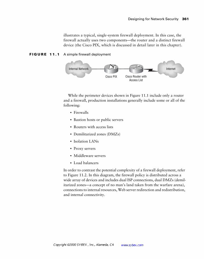
Designing for Network Security 361
illustrates a typical, single-system firewall deployment. In this case, the firewall actually uses two components—the router and a distinct firewall device (the Cisco PIX, which is discussed in detail later in this chapter).
F I G U R E 1 1 . 1 A simple firewall deployment
While the perimeter devices shown in Figure 11.1 include only a router and a firewall, production installations generally include some or all of the following:
� Firewalls
� Bastion hosts or public servers
� Routers with access lists
� Demilitarized zones (DMZs)
� Isolation LANs
� Proxy servers
� Middleware servers
� Load balancers
In order to contrast the potential complexity of a firewall deployment, refer to Figure 11.2. In this diagram, the firewall policy is distributed across a wide array of devices and includes dual ISP connections, dual DMZs (demil-itarized zones—a concept of no man’s land taken from the warfare arena), connections to internal resources, Web server redirection and redistribution, and internal connectivity.
Cisco PIX
InternetInternal Network
Cisco Router withAccess List
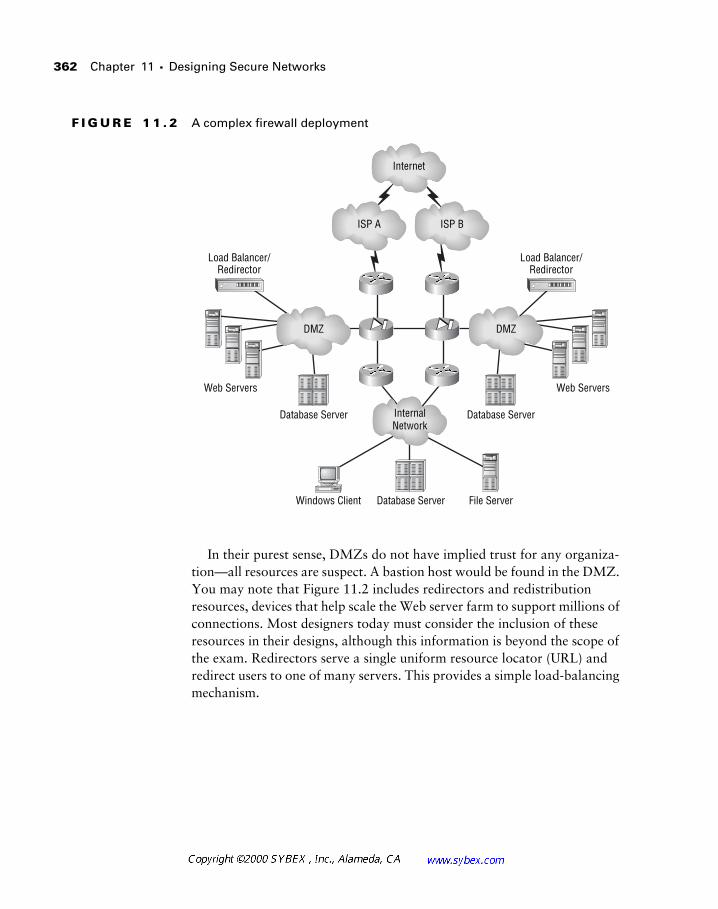
362 Chapter 11 � Designing Secure Networks
F I G U R E 1 1 . 2 A complex firewall deployment
In their purest sense, DMZs do not have implied trust for any organiza-tion—all resources are suspect. A bastion host would be found in the DMZ. You may note that Figure 11.2 includes redirectors and redistribution resources, devices that help scale the Web server farm to support millions of connections. Most designers today must consider the inclusion of these resources in their designs, although this information is beyond the scope of the exam. Redirectors serve a single uniform resource locator (URL) and redirect users to one of many servers. This provides a simple load-balancing mechanism.
Windows Client File Server
Web Servers Web Servers
Database Server
Database Server Database ServerInternalNetwork
DMZ DMZ
ISP A ISP B
Internet
Load Balancer/Redirector
Load Balancer/Redirector
Designing for Network Security 363
It may not be readily apparent, but the security offered by the network in Fig-ure 11.2 is poor at best. The illustration is not intended to show a good design, but rather one that uses various components.
Implementing a Security Policy
There is more to implementing a security policy than purchasing and install-ing a firewall, even if the deployment is limited to this single mechanism. The implementation needs to include the policy itself, the acquisition and config-uration of the various components, and installation, testing, and auditing.
An effective security policy, which provides a road map for the actual security deployment, should include the following elements:
A simple, fault-tolerant design This design does not necessarily require redundant systems, but should include solid hardware components and battery backup systems. In addition, if the staff is familiar with Unix, it makes little sense to implement an NT-based firewall. The reverse is also true. The exception to this rule is performance and inherent security; many NT firewalls lag behind their Unix counterparts in terms of perfor-mance. Note that dedicated hardware platforms, including Cisco’s PIX, are also an option. However, new hardware often requires additional training.
Expense relative to the required security It makes little sense to spend $500,000 to secure $40,000 worth of information. However, designers must include the cost of downtime and lost productivity in their calcula-tions. In addition, it is hard to quantify raw data costs; sometimes planners need to use another determination metric, such as market capitalization, to bolster their case. This guideline also relates to the amount of security required—most expensive solutions provide many features that would go unused in smaller organizations.
Understanding what data should be accessible by outsiders This step should be part of the initial security document described in the beginning of this chapter, though a more thorough understanding will be required. In addition, it is appropriate to consider access methodologies including private circuits, encryption, and single-use authentication.
364 Chapter 11 � Designing Secure Networks
Strong monitoring and logging features The best firewall solutions are worthless if the administrator is not warned of an attack or breach. This part of the security policy may directly relate to the cost of the solution, though not necessarily. Available to the administrator are several afford-able options, which may consist of little more than syslog (system log) output. More expensive solutions typically provide filtering and other fea-tures to reduce the volume of messages requiring the administrator’s attention.
It may be appropriate to hire a dedicated specialist to address your firm’s security needs. This person may be an employee reassigned from another position, a new hire, or a consultant. Consultants may yield the cheapest deployment given their experience with different organizations and equip-ment. If you hire a consultant, make sure that they warrant the trust that your firm will be placing in them and that everything they do is documented. It is always a good idea to conduct a thorough background review, as well as to check references. Non-disclosure agreements are also helpful, though it may be difficult to provide sufficient legal proof of breach for this to fully protect the organization.
Always have a second person trained on the security systems and technology. People leave jobs and fall ill—either way, there will be a lack of support.
Detecting and Addressing Attacks
The best security plans include an auditable and verifiable component. It is one thing to prevent the attack in the first place, but if the administrator can-not ascertain that all attacks have been unsuccessful, there is a significant risk to the corporation.
Logging is one of the best methods for capturing the techniques used in an attack and for determining which resources were compromised. However, administrators must realize that truly skilled hackers can easily hide their activity or purge the logs if they are improperly stored. Thus, logs should always be written to a separate system with another layer of security between devices.
Designing for Network Security 365
Logs should always be written to a secure server other than to the firewall itself. Once the firewall is compromised, a hacker can easily purge the log files, which are the best form of documentation for criminal prosecution.
Honey Pots
Remember Winnie-the-Pooh? He was a stuffed bear that came to life and, like most bears, loved honey. One of many themes in the Pooh stories was Winnie getting stuck because of his love of honey; one tale had his arm trapped in a honey pot, a vessel with a small opening used for storing honey.
Well, in the network security arena, honey pots build upon this very idea: Attackers want the honey, and they may get trapped if they try to obtain it.
Basically, the honey pot is a special fictional system designed to appear like the corporate data being sought—and designed to be hacked. Once an attack is detected by the firewall, the system redirects the session to the fic-tional data and invokes additional logging to capture information regarding the attack and the hacker.
This recent trend in data security provides two benefits. First, the hacker thinks he’s successful when in fact the live data is still protected. Second, detailed information regarding the attack hacker is obtained for authorities. This information may include:
� Traceroute and ping information regarding the attacker
� DNS information regarding the attacker’s host
� Detailed logs of every command and application used in the attack
� Time and date of the attack
� Real-time notification of the attack
� Finger, whois, and other information regarding the attacker
Unfortunately, for the average designer/administrator, little may come from documenting an attack, especially if the attack is launched from another country. The U.S. legal system is just now starting to discover the limitations of local laws in international events, and the majority of the writ-ten laws fail to address computing and networking at all. In fact, a California district attorney recently used a horse-trading law from over 100 years ago
366 Chapter 11 � Designing Secure Networks
to charge a man who allegedly ran fraudulent auctions on the Internet—no other regulation was relevant.
Another problem that honey pots do not address is that some software still focuses on port scans from a single IP address to trigger an attack warn-ing. Many hackers have gotten together to launch large-scale attacks with scans originating from hundreds of machines, fooling the software into thinking that there are a lot of “dumb users” out there. This type of attack should be considered in feature evaluations when selecting a firewall vendor.
Network Design in the Real World: Social Engineering Attacks
If it wasn’t clear from the first chapter, I will state here and now that I enjoy the humanistic side of business and computing as much as the technical. In fact, I think that I’d be bored if I only built networks and couldn’t deal with the human issues.
So now you’re saying, “Who cares?” Fine, but let me explain anyway. I note the dual-faceted nature of my career as an introduction to the social engi-neering attack—an attack methodology that can defeat even the best fire-walls. I love it because it is simple and proves once again that mice can become smarter than the mousetrap. Different social engineering attacks work in different ways, but my two favorites are the fake circuit and the CEO support attacks.
The fake circuit attack actually occurs with the installation of a real circuit (despite its misleading name); it typically hits small, remote offices with lit-tle or no on-site support. The attack succeeds because most corporations fail to work with the staff in these locations when it comes to networking. Generally, attackers using this technique pose as telephone company employees and pretend to install a new T1 for an “upgrade project.” In real-ity, the circuit is simply a short connection that connects to a cheap piece of hardware installed by the hacker. Wireless technology has made this tech-nique even easier, but the net gain from the attack is internal access to the corporate data system.
Designing for Network Security 367
Security Design Failures
In general, most security designs fail for at least one of the following reasons:
� The solution or issue is misunderstood.
� Securing against the threat is too complex.
� Securing against the threat is too costly.
� The design poses a threat to other corporate structures.
� Data security is superseded by other objectives within the organization.
Most corporations have very detailed security plans that are signed by every employee under threats of termination and prosecution for violators. Unfortunately, more often than not, these documents are unenforced. Note that these documents are different from a security policy statement.
The CEO support attack is a work of wonder. As with the fake circuit attack, it operates on the premise that most people want to be helpful. The attacker selects a victim and calls the secretary of the CEO or other executive who likely has a high level of access to the company systems. The cover story is that the CEO reported a problem with an application on their machine, and the attacker, posing as a member of technical support, wishes to test the modifications on the server to make sure the problem was resolved cor-rectly. Once given the password, the hacker can then use another access method, perhaps a dial-in line, to gain access to the company’s information. This attack works best if the attacker appears to be calling from an internal number. However, it works in many cases because the secretary wants to help and the administrator could always get to the files anyway—the pre-sumption being that server administrators can access all files on the server, regardless of ownership or rights.
You may be asking what good a system password is if the hacker does not have access to the system. Good point. Ask yourself what happens if the remote access system uses the bindery/NDS or NT directory for authenti-cation—the attacker gets in through the same system designed to prevent such an attack. Again, even the best firewalls will fail to flag this type of sce-nario, and ultimately some data may be compromised.
368 Chapter 11 � Designing Secure Networks
Consider the following corporate security issues as they relate to three specific categories.
� Corruption of data, typically in the form of introducing erroneous information
� Viruses
� Destruction of data, typically in the form of deleting files
� Theft of data
� Leakage of proprietary information
� Theft/destruction of computing resources
� Abuse of data/access
� Employee access abuse
� Unauthorized access by outsiders
� Access abuse by non-employee authorized users
� Hacking of phone/PBX/VM. The PBX, or public branch exchange, and the voice mail (VM) system can provide the attacker with free phone access or a means to tarnish the corpo-rate image—consider the impact if everyone’s voice mail announced to callers that the company went bankrupt.
At first glance, there would appear to be little a network designer could do to thwart all of the above items other than understand the corporate culture and assist in the education of both management and workers. In fact, most network administrators and designers hold to the premise that the network is not a security device, and to a certain degree an argument in favor of this position can be made. However, as with most other problems, a solution that involves various components can frequently address the issue better than a single option. In this vein, designs may incorporate services or options that each address a part of the problem.
For example, consider the first security issue—corruption of data. Clearly, a good backup strategy is the best solution to this problem, because an off-site, near real-time copy of the data counteracts the damage done by fires, floods, and user errors (including the inevitable deletion of that critical
Designing for Network Security 369
sales file). However, this solution does not offer a prevention phase—a chance to prevent the problem from occurring. The network designer may choose a firewall/proxy product that incorporates virus scanning of all files that are accessed from the Internet, yet this solution will fail to address all virus infections—a floppy brought in by an employee could quickly circum-vent all detection efforts at the firewall.
Network Design in the Real World: Network Attacks
A recent ZDNet publication provided hackers with the opportunity to attack a specially established network with a typical security model. The site pro-vided Linux- and NT-based Web servers and used general firewall software, in addition to application-level security, on each server.
The first successful attack made on this network did not defeat the front-end firewall or any of the access lists on the routers—two typical security methods used by network designers and administrators. These devices blocked the failed attempts and permitted only the approved traffic to access the site.
The attackers ultimately created a suidroot shell (a means to gain root, or super-user access) in a directory accessible by the hacker. While this required a fairly detailed level of CGI, C, and Linux knowledge, the attack showed how easy it is to defeat the network designer’s primary tools. Few network architects concern themselves with server security, but a partner-ship with the groups that do can significantly improve the overall security model.
There are a number of ways to reduce the likelihood of a successful network attack. First, most servers provide information to all systems regarding their operating system version and applications. A hacker may use this informa-tion to find bugs and opportunities specific to that software. Designers and server administrators should work together to block all unnecessary iden-tification information from being sent to clients.
370 Chapter 11 � Designing Secure Networks
Network Security Solutions
A wide array of tools and methods are available to the network designer for providing protection against attacks. This section presents a number of solutions for the network designer to consider and use as part of an overall security model. Firewalls, the Cisco PIX, caching, access lists, address translation, and encryption can all work together to provide a strong security presence.
Firewalls
Firewalls have been regarded as the sole critical protection from the evils of the Internet. While firewalls are helpful, this position is inaccurate. Firewalls do not provide complete protection from external threats. They offer a single point of attack, and, according to the latest surveys (1998), most attacks avoid the firewall as a contention point altogether. These attacks may be accomplished via dial-up, social engineering, or backdoor tactics, but the net result is the same.
In addition, most firewalls are deployed without concern to internal threats. Designers should always consider the possibility of internally
Second, many of the techniques used in this case study were published and/or patched mere days before the attack. While such monitoring is impractical, a technician constantly monitoring the various hacking Web sites may discover a technique to defeat the attack in time to implement a solution. Many companies rely on their vendors to perform this task, though restrictive permissions on the server and firewall can greatly dimin-ish the number of techniques that can be used. To provide the best security for the corporation, security technicians and designers must become hack-ers themselves—similar to the way law enforcement officers profile crimi-nals—although this activity must be balanced with the other tasks required by the organization.
A colleague at Cisco likes to cite the quote “The question isn’t if you’re para-noid. The question is, ‘Are you paranoid enough?’” Well-placed paranoia can be a very useful tool so long as it does not result in paralysis.
Network Security Solutions 371
sourced attacks, including those that exploit internal systems from the out-side—an attack scenario that starts with an external host compromising an internal, trusted host and then using that trusted host to attack another inter-nal resource.
The best firewalls offer the designer solid security options with easy administration and configuration. Application-level firewalls go far beyond the basic protocol-based selection process available from a router. For exam-ple, many firewalls can block Java applets within HTTP streams—the router could only permit or deny HTTP. A router cannot block Java or ActiveX applets, nor can it provide virus-scanning functions. Many firewalls can pro-vide these services.
Protecting the Router-Based Firewall
There are many arguments in favor of using firewalls as opposed to routers for protecting the perimeter of a network. For our purposes, a firewall has awareness beyond Layer 4, while also performing a routing function.
Cisco has introduced the IOS Firewall Feature Set, which adds some firewall functionality to the basic port filtering available in access lists. Designers will have to evaluate the appropriateness of this solution against other systems, including Gauntlet, Sidewinder, the Cisco PIX, and Checkpoint.
However, even with these systems it is important to provide whatever protection you can for the firewall itself. This frequently warrants some con-figuration of the router for basic, front-line security. Your efforts should include the following:
� Use static routes. This protects against route spoofing, where the attacker redirects data to resources they control. Route spoofing is one of the top techniques used by internal hackers.
� Do not configure the router for additional services, including TFTP.
� Disable Telnet access to the router and use a locally attached console. If this is not practical, use an access list to permit a handful of addresses to the VTY interfaces, and then allow only data flowing into the internal interface from an authorized source.
372 Chapter 11 � Designing Secure Networks
� Disable small servers on the router. Cisco considers a number of ser-vices to be part of the small servers keyword, including the echo and finger services.
� Use the password-encryption features, ideally using TACACS+ for authentication.
� Disable proxy ARP.
� Disable or strengthen security on SNMP services. Deny these services on the external interface.
� Block Telnet access to internal resources from external hosts and the firewall. Blocking firewall-sourced Telnet sessions requires placing a router inside the firewall; once compromised, the firewall can no longer be trusted to provide this protection.
In addition, administrators should invoke interface-level access lists on the front-line router. These access lists should protect both the front-line router and the firewall. The only drawback to this method is reduced router performance, though placing a short list on a reasonable routing platform should add only negligible delay. NetFlow and other technologies can reduce the impact of access lists on router performance and should be evaluated against the specific hardware in use. Inbound access lists can impact perfor-mance more than outbound ones; however, it is more secure to block on the inbound interface, and doing so negates the need for a routing lookup. The specific placement of access lists in your network will depend on the type of router, the type of IOS, and the level of security required.
Network Design in the Real World: SNMP Security
When working for a fairly small company, I had a small router connected to an Internet Service Provider—a router that also functioned as a limited fire-wall. The ISP recommended that they monitor our router for us, since we had no 24-hour staffing and no remote monitoring services at the time. I recommended that we allow only pings for monitoring, but I was outvoted and soon enabled SNMP using the ISP’s default passwords.
Network Security Solutions 373
The Cisco PIX
Cisco provides a stateful-inspection firewall with its Packet Internetwork Exchange (PIX) product line. Stateful-inspection firewalls do not examine each packet through the application layer—rather, they analyze the begin-ning of the data flow and then maintain information about that flow’s state. State is comprised of IP addresses, sequence numbers, and ports used. The benefit of the stateful-inspection firewall is that it is typically much faster
Needless to say, the access list rules were disabled within three months, and we were unfiltered to the Internet. We caught the problem as part of a weekly, manually initiated audit process—the syslog feature on the router was unreliable. (Note that this was not a Cisco router, although the same problems could exist on a Cisco-based platform.) The router was compro-mised because it was protected from SNMP attacks only by a simple, unen-crypted password (clear-text) and an IP address restriction. Further, while the ISP never admitted that it had been hacked, there is little doubt that someone (either inside or outside the ISP) compromised the machine (or spoofed the IP address) that was given access and used it to attack us.
The immediate response to this attack was to disable the SNMP mechanism and re-enable the filters. A full audit of all systems did not detect any further compromises.
Designers should take a few lessons away from this story. First, don’t trust an ISP or any outside source to be secure. This is very hard to implement in practice—I worked on one network where the ISP was the maintainer of the firewall, and the IS staff was completely blocked from any involvement. This is a very poor practice, though many companies lack the internal staff resources necessary to properly maintain a firewall. In my opinion, when this function gets outsourced, the mindset shifts to one of blame distribu-tion rather than security, which is never good.
The second lesson is to always push for another solution. I didn’t do this once management had made their decision, though I knew that SNMP was not secure (since version 2 uses clear-text passwords), and neither was a single-firewall router design. Unfortunately, I was unsuccessful in getting the budget for an internal firewall or the proper resources to manage and monitor the router.
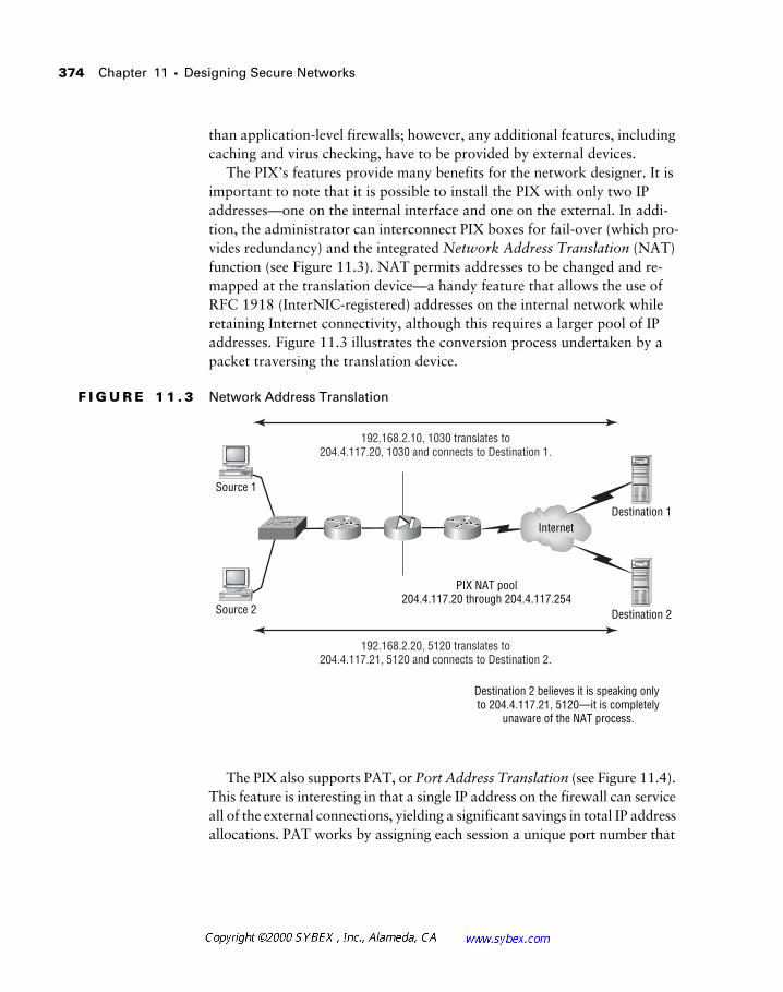
374 Chapter 11 � Designing Secure Networks
than application-level firewalls; however, any additional features, including caching and virus checking, have to be provided by external devices.
The PIX’s features provide many benefits for the network designer. It is important to note that it is possible to install the PIX with only two IP addresses—one on the internal interface and one on the external. In addi-tion, the administrator can interconnect PIX boxes for fail-over (which pro-vides redundancy) and the integrated Network Address Translation (NAT) function (see Figure 11.3). NAT permits addresses to be changed and re-mapped at the translation device—a handy feature that allows the use of RFC 1918 (InterNIC-registered) addresses on the internal network while retaining Internet connectivity, although this requires a larger pool of IP addresses. Figure 11.3 illustrates the conversion process undertaken by a packet traversing the translation device.
F I G U R E 1 1 . 3 Network Address Translation
The PIX also supports PAT, or Port Address Translation (see Figure 11.4). This feature is interesting in that a single IP address on the firewall can service all of the external connections, yielding a significant savings in total IP address allocations. PAT works by assigning each session a unique port number that
192.168.2.10, 1030 translates to204.4.117.20, 1030 and connects to Destination 1.
192.168.2.20, 5120 translates to204.4.117.21, 5120 and connects to Destination 2.
Internet
PIX NAT pool204.4.117.20 through 204.4.117.254
Destination 2 believes it is speaking only to 204.4.117.21, 5120—it is completely
unaware of the NAT process.
Source 2
Source 1
Destination 1
Destination 2
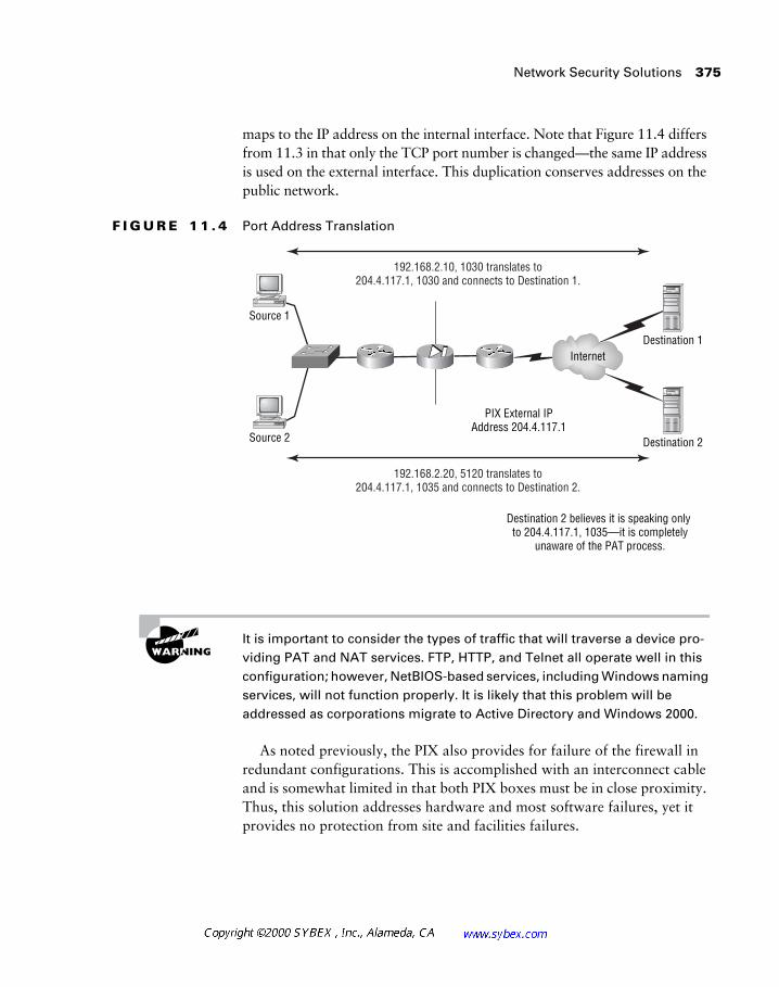
Network Security Solutions 375
maps to the IP address on the internal interface. Note that Figure 11.4 differs from 11.3 in that only the TCP port number is changed—the same IP address is used on the external interface. This duplication conserves addresses on the public network.
F I G U R E 1 1 . 4 Port Address Translation
It is important to consider the types of traffic that will traverse a device pro-viding PAT and NAT services. FTP, HTTP, and Telnet all operate well in this configuration; however, NetBIOS-based services, including Windows naming services, will not function properly. It is likely that this problem will be addressed as corporations migrate to Active Directory and Windows 2000.
As noted previously, the PIX also provides for failure of the firewall in redundant configurations. This is accomplished with an interconnect cable and is somewhat limited in that both PIX boxes must be in close proximity. Thus, this solution addresses hardware and most software failures, yet it provides no protection from site and facilities failures.
192.168.2.10, 1030 translates to204.4.117.1, 1030 and connects to Destination 1.
192.168.2.20, 5120 translates to204.4.117.1, 1035 and connects to Destination 2.
Internet
PIX External IPAddress 204.4.117.1
Destination 2 believes it is speaking only to 204.4.117.1, 1035—it is completely
unaware of the PAT process.
Source 2
Source 1
Destination 1
Destination 2
376 Chapter 11 � Designing Secure Networks
Caching
While bandwidth is becoming cheaper and more widely available, there are still many benefits to caching. When data is cached, the data elements are copied and provided from sources closer to the requestor. The cache is the collection of data elements that are provided.
Consider a Web page with three large graphics. It takes 10 seconds to download those graphics across the Internet with a T1. If a company cached Web traffic, the first employee would take 10 seconds to load the page, but each subsequent employee would receive it in a fraction of that time—per-haps a single second. The cache serves the data from a local resource, rather than requiring another transfer from a remote location. This results in more efficient use of the T1, the Internet, and the Web server, while providing the user a better response time.
Internet Service Providers have begun to place caches in their networks to further accelerate the distribution of data. This method again improves per-formance and yields a cheaper solution. Consider caches as you would com-muting options. Adding lanes for more cars is significantly less efficient than using a train, bus, or ferry. While there are times when bigger pipes are required, it is best to evaluate the actual need. There are also instances where it’s best to take another tack—personally, I look at adding extra lanes for cars like I do combating obesity by getting larger pants. The same is true in networking—more bandwidth will not decrease the performance bottleneck caused by large, uncompressed graphics.
From a security perspective, caching can be problematic, although this problem is diminishing as the technology advances. The original issue was that pages viewed were stored on the caching server and could be viewed without authentication. As more sites employ Secure Hypertext Transfer Protocol (HTTPS) and non-caching flags, this problem should subside. Administrators can reduce this risk by securing the caching server as they would any other corporate resource.
Access Lists
An access list provides the ability to block or permit traffic based on address, port number, and/or the concept of established communications. There is no awareness of upper-layer protocols, and thus protection against application-layer attacks is not available. A significant number of companies continue to use router access lists as the sole means of securing their networks. Yet, while
Network Security Solutions 377
such lists certainly belong in most security deployments, the access list itself is fairly limited.
One of the misunderstood components in an access list is the established keyword—there is no bona fide established bit or validation of sequence numbers. Rather, the established keyword requires packets to have the ACK (acknowledgment) bit set. The acknowledgment bit is set on the second packet in the TCP three-way handshake that starts all sessions, as well as on all subsequent packets. The router presumes that any inbound packet with an ACK bit is in response to a datagram sent by the trusted station. One denial-of-service (DOS) attack made use of this characteristic—the SYN-ACK flood operated by sending a large number of packets to the target with both the SYN and ACK bits set. Most systems would overflow their buffers in servicing the traffic.
The established keyword is used in a different context on the PIX firewall and should not be confused with the description in this section.
The FIN (finished) bit will also pass the established filter.
Thwarting address spoofing is another common use of access lists. This technique prevents IP addresses outside the network from entering and pos-sibly taking advantage of permissions granted to internal resources. To con-figure this solution, the administrator blocks all internal addresses from being the source address on the external interface.
Time-Based and Reflexive Access Lists
Two new kinds of access lists have been added to the most recent versions of the IOS. Time-based access lists provide designers with the ability to activate security policies based on the time of day or the day of the week. This is an interesting conflict in traditional security policies—normally anything that is not permitted is never permitted. Time-based lists alter this situation by allowing specific functions to traverse the router at certain times. These lists might be used to allow backups to run in the middle of the night from servers in the DMZ, for example. Unfortunately, this would also permit hackers to exploit the increased permissions in order to launch an attack.
378 Chapter 11 � Designing Secure Networks
There is little doubt that administrators will use time-based access lists. However, to do so without fully incorporating the feature with a security policy would be irresponsible.
Reflexive access lists go beyond the traditional “permit all established” access lists by incorporating reflexive technology. A reflexive list permits traffic only in response to a prior event—an originating packet from the internal network, for example.
Perhaps the best way to understand the operation of a reflexive access list is to consider the configuration used, which is shown in the following output:
interface hssi 3/0
description Interface to Inet
ip access-group in-filter in
ip access-group out-filter out
ip reflexive-list timeout 120
ip access-list extended in-filter
permit tcp any 10.11.2.0 0.0.0.255 reflect allowed
(Note the implicit deny)
ip address-list extended out-filter
deny icmp any any
deny udp any any
evaluate allowed
In this example, the serial 0 interface is configured with inbound- and outbound-named access lists. The outbound filter denies ICMP and UDP traffic and then references the reflexive tcp traffic filter—a filter that permits the return of any TCP traffic that originates inside the network. This is similar to the established bit, but the advantage is that this permission exists only for 120 seconds or for the duration of the TCP session—a significant reduction in the amount of time a hacker might have to exploit the permission. Note that the default timeout value is 300 seconds, which applies to lost TCP ses-sions and connectionless UDP sessions. Reflexive access lists work with UDP traffic; however, the termination of the reflexive access list permission is based only on the timer.
Network Security Solutions 379
Encryption
The concept of encryption is best exemplified by the childhood code games that most pre-teens play. These games send secret messages composed of off-sets—for example, each letter may be three characters removed from the actual letter. Thus, the letter D might represent the letter A, and the letter Z would be represented with the letter C.
Obviously, such a simple code would be fairly easy to crack. In wartime, such codes incorporated garbage characters, floating offsets, and other tech-niques to provide additional protection. By World War II, these ciphers had become quite advanced and made use of simple computers that added addi-tional randomness to the sequence. A famous Allied victory incorporated the cracking of a German code—a victory made possible only because a German officer transmitted the same message twice. By dissecting the pattern, the Americans and the British were able to build their own computer for decod-ing the secret messages.
With today’s computational power, the ability to encode and decode data streams is fairly simple, and a wide variety of methods may be employed. The majority of these methods incorporate the concept of a key, or pass-word, and the number of bits used for the key directly relates to the potential security afforded by the encryption. A key is the base code used to calculate the encryption code. For example, the formula for my encryption code might be to add two and subtract one, but if I allow the user to define the initial number, the result should be different from those of other users (clearly this is a very simple example).
Recently, the United States government took steps to authorize the export of higher-security encryption keys to 128 bits. Prior to this time, export keys were restricted to 56 bits, and munitions laws governed the use of higher encryption key values.
This text does not address specific technologies for encryption given the ever-changing landscape of the encryption marketplace. However, it is clear that a standard will emerge and that at least 128-bit keys will be required to provide the required level of protection.
An educational and military effort is currently working on a chaos encryption system. This system would operate on the premise that back-ground noise can be used to filter the underlying data stream and that such
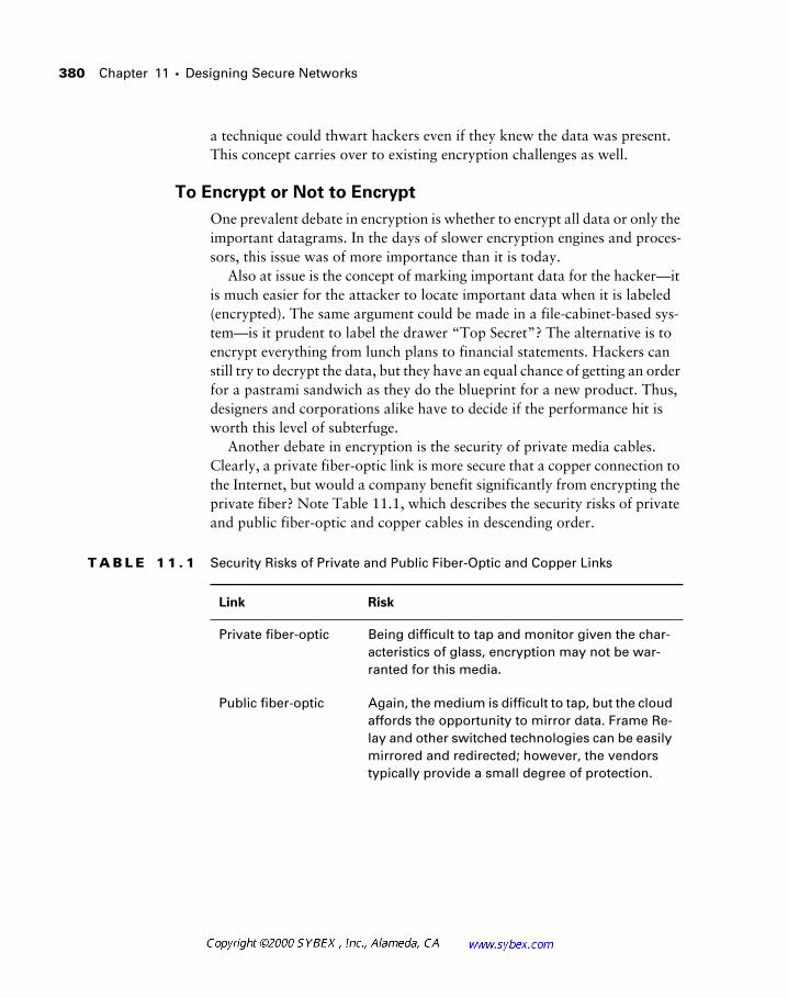
380 Chapter 11 � Designing Secure Networks
a technique could thwart hackers even if they knew the data was present. This concept carries over to existing encryption challenges as well.
To Encrypt or Not to Encrypt
One prevalent debate in encryption is whether to encrypt all data or only the important datagrams. In the days of slower encryption engines and proces-sors, this issue was of more importance than it is today.
Also at issue is the concept of marking important data for the hacker—it is much easier for the attacker to locate important data when it is labeled (encrypted). The same argument could be made in a file-cabinet-based sys-tem—is it prudent to label the drawer “Top Secret”? The alternative is to encrypt everything from lunch plans to financial statements. Hackers can still try to decrypt the data, but they have an equal chance of getting an order for a pastrami sandwich as they do the blueprint for a new product. Thus, designers and corporations alike have to decide if the performance hit is worth this level of subterfuge.
Another debate in encryption is the security of private media cables. Clearly, a private fiber-optic link is more secure that a copper connection to the Internet, but would a company benefit significantly from encrypting the private fiber? Note Table 11.1, which describes the security risks of private and public fiber-optic and copper cables in descending order.
T A B L E 1 1 . 1 Security Risks of Private and Public Fiber-Optic and Copper Links
Link Risk
Private fiber-optic Being difficult to tap and monitor given the char-acteristics of glass, encryption may not be war-ranted for this media.
Public fiber-optic Again, the medium is difficult to tap, but the cloud affords the opportunity to mirror data. Frame Re-lay and other switched technologies can be easily mirrored and redirected; however, the vendors typically provide a small degree of protection.
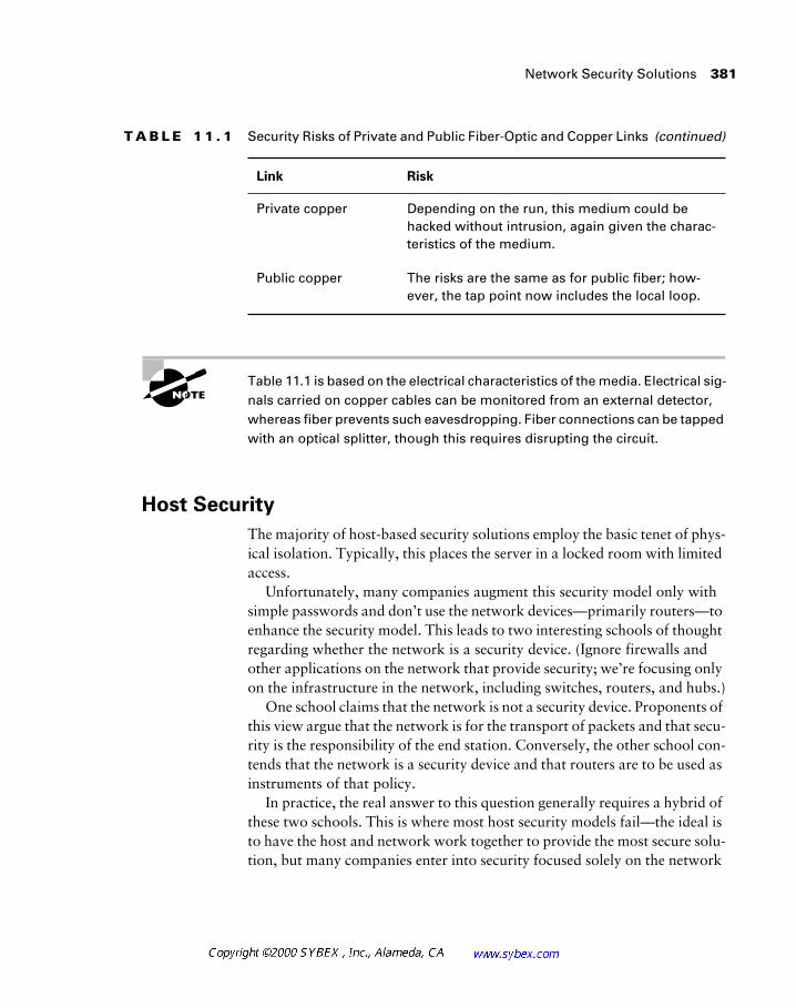
Network Security Solutions 381
Table 11.1 is based on the electrical characteristics of the media. Electrical sig-nals carried on copper cables can be monitored from an external detector, whereas fiber prevents such eavesdropping. Fiber connections can be tapped with an optical splitter, though this requires disrupting the circuit.
Host Security
The majority of host-based security solutions employ the basic tenet of phys-ical isolation. Typically, this places the server in a locked room with limited access.
Unfortunately, many companies augment this security model only with simple passwords and don’t use the network devices—primarily routers—to enhance the security model. This leads to two interesting schools of thought regarding whether the network is a security device. (Ignore firewalls and other applications on the network that provide security; we’re focusing only on the infrastructure in the network, including switches, routers, and hubs.)
One school claims that the network is not a security device. Proponents of this view argue that the network is for the transport of packets and that secu-rity is the responsibility of the end station. Conversely, the other school con-tends that the network is a security device and that routers are to be used as instruments of that policy.
In practice, the real answer to this question generally requires a hybrid of these two schools. This is where most host security models fail—the ideal is to have the host and network work together to provide the most secure solu-tion, but many companies enter into security focused solely on the network
Private copper Depending on the run, this medium could be hacked without intrusion, again given the charac-teristics of the medium.
Public copper The risks are the same as for public fiber; how-ever, the tap point now includes the local loop.
T A B L E 1 1 . 1 Security Risks of Private and Public Fiber-Optic and Copper Links (continued)
Link Risk
382 Chapter 11 � Designing Secure Networks
and firewalls. From a security perspective, using simple access lists and strong passwords along with giving much consideration to performance will likely yield the best solution.
Of course, one of the risks in data security is developing a solution that impedes productivity. A perfect example of this in the workstation world is the analog modem. Many companies approve the installation of a measured business phone line, not realizing that the employee can use it with remote-control software. The user unintentionally thwarts the security policy by installing a program that can provide a connection via the phone line. Once the attacker controls the machine connected to both the modem and the LAN, they can access corporate resources on the network. This circumvents any protections installed by the network designer or administrator.
Authentication and Authorization
The security triad is composed of three distinct functions: authentication, authorization, and accounting. (The accounting function will be described in the following section.) Authentication and authorization work hand-in-hand to provide the proper parties with the access permitted. Authentication typically includes a user identification and password, though some systems use tokens (something you have and something you know). Token systems are similar to bank ATM cards—I have the card, and I know my PIN. Autho-rization operates once an individual has been authenticated, and this process defines what may or may not be allowed. For example, you may know the enable password, but your user account will not authorize the use of the enable command.
Together, these methods provide better protection than either one on its own. Newer systems are using voice-print technology and fingerprinting, in addition to optical scanners that image the face or retina. Programs that record the cadence of keystrokes have been around for years—they operate on the premise that everyone types a bit differently than others. So you may know my password is “secret,” but unless you pause between the c and r, the system will not let you in.
It is possible to maintain databases on these devices in order to provide authentication and authorization, but it should be clear that this solution is very limited and will not scale. Two of the more popular centralization sys-tems/protocols used are TACACS+ (Enhanced Terminal Access Controller Access Control System) and RADIUS (Remote Access Dial-In User Service).
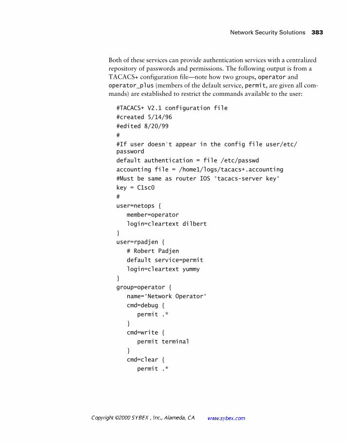
Network Security Solutions 383
Both of these services can provide authentication services with a centralized repository of passwords and permissions. The following output is from a TACACS+ configuration file—note how two groups, operator and operator_plus (members of the default service, permit, are given all com-mands) are established to restrict the commands available to the user:
#TACACS+ V2.1 configuration file
#created 5/14/96
#edited 8/20/99
#
#If user doesn't appear in the config file user/etc/password
default authentication = file /etc/passwd
accounting file = /home1/logs/tacacs+.accounting
#Must be same as router IOS "tacacs-server key"
key = C1sc0
#
user=netops {
member=operator
login=cleartext dilbert
}
user=rpadjen {
# Robert Padjen
default service=permit
login=cleartext yummy
}
group=operator {
name="Network Operator"
cmd=debug {
permit .*
}
cmd=write {
permit terminal
}
cmd=clear {
permit .*
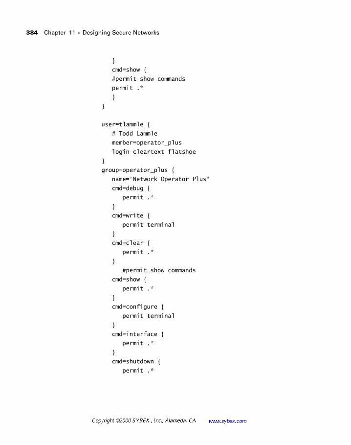
384 Chapter 11 � Designing Secure Networks
}
cmd=show {
#permit show commands
permit .*
}
}
user=tlammle {
# Todd Lammle
member=operator_plus
login=cleartext flatshoe
}
group=operator_plus {
name="Network Operator Plus"
cmd=debug {
permit .*
}
cmd=write {
permit terminal
}
cmd=clear {
permit .*
}
#permit show commands
cmd=show {
permit .*
}
cmd=configure {
permit terminal
}
cmd=interface {
permit .*
}
cmd=shutdown {
permit .*
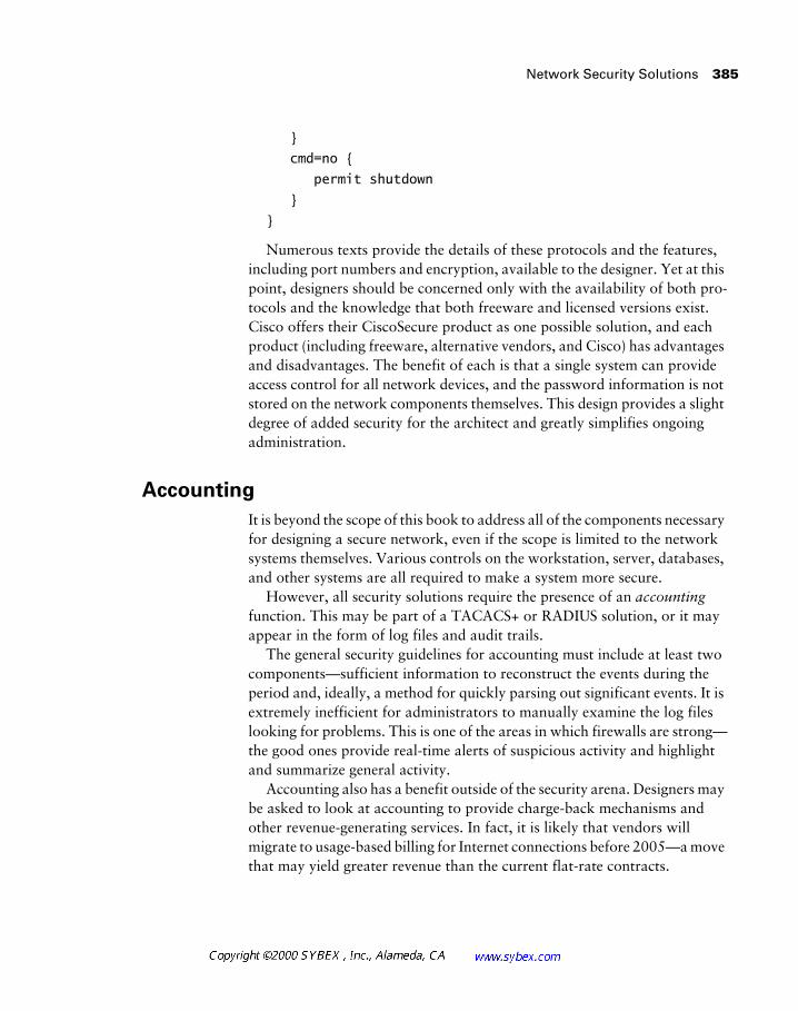
Network Security Solutions 385
}
cmd=no {
permit shutdown
}
}
Numerous texts provide the details of these protocols and the features, including port numbers and encryption, available to the designer. Yet at this point, designers should be concerned only with the availability of both pro-tocols and the knowledge that both freeware and licensed versions exist. Cisco offers their CiscoSecure product as one possible solution, and each product (including freeware, alternative vendors, and Cisco) has advantages and disadvantages. The benefit of each is that a single system can provide access control for all network devices, and the password information is not stored on the network components themselves. This design provides a slight degree of added security for the architect and greatly simplifies ongoing administration.
Accounting
It is beyond the scope of this book to address all of the components necessary for designing a secure network, even if the scope is limited to the network systems themselves. Various controls on the workstation, server, databases, and other systems are all required to make a system more secure.
However, all security solutions require the presence of an accounting function. This may be part of a TACACS+ or RADIUS solution, or it may appear in the form of log files and audit trails.
The general security guidelines for accounting must include at least two components—sufficient information to reconstruct the events during the period and, ideally, a method for quickly parsing out significant events. It is extremely inefficient for administrators to manually examine the log files looking for problems. This is one of the areas in which firewalls are strong—the good ones provide real-time alerts of suspicious activity and highlight and summarize general activity.
Accounting also has a benefit outside of the security arena. Designers may be asked to look at accounting to provide charge-back mechanisms and other revenue-generating services. In fact, it is likely that vendors will migrate to usage-based billing for Internet connections before 2005—a move that may yield greater revenue than the current flat-rate contracts.
386 Chapter 11 � Designing Secure Networks
Virtual Private Networks
At present, virtual private networks (VPNs) are not included in the CID exam objectives. However, this relatively new functionality can greatly reduce costs and management issues in the network and should be consid-ered with care by designers. Most VPN deployments build upon the basic concepts of tunneling and add security to the offering. At its simplest defini-tion, a VPN is a tunnel between two points across an untrusted or public net-work. The contents of the tunnel are typically encrypted, reducing the risk that a session would be intercepted and the data compromised.
The biggest benefit of VPNs, their low cost, is the result of local points-of-presence—users dial a local number rather than an 800 number or a long-distance one. There is little doubt that low access costs will make VPNs a common service in the network. However, many corporations are having difficulty deploying the service for technical and political reasons. Most fre-quently, the political reasons involve a lack of trust regarding the security of VPNs and the reliability of using the public network for business-critical data. Many vendors now offer guaranteed service levels for VPN traffic that remains within their network.
Another advantage to VPN technology is the flexibility afforded the designer. The typical remote-access solution, which VPN is designed to replace, requires the designer and administrator to order circuits at both the local and remote ends. These circuits are usually user-specific—user A might use ISDN and user B might use analog dial-up. Even with discounts and 800 numbers, the costs for these services quickly grow and significantly add to the burdens of the support organization. It is not unheard of for users to generate monthly ISDN charges of thousands of dollars. In addition, users are limited to the remote technology deployed for them.
VPN technology simplifies this model substantially as a single point (fore-going redundancy) that can provide connectivity for an array of access meth-ods, including cable modems, DSL, dial-up, ISDN, and Frame Relay. A wide array of protocols and methods, including the Point-to-Point Tunneling Pro-tocol (PPTP), L2F (Layer 2 Forwarding), L2TP (Layer 2 Tunneling Proto-col), and IPSec (IP Security), are available to encrypt data and provide secure “virtual” connections between the access points. Each technology provides different standards and benefits, including support for multiple protocols, NAT, and multicasts.
Virtual Private Networks 387
However, the landscape is changing very quickly, and readers are advised to examine vendor materials and standards documents before selecting a technology. Note that at present, though IPSec appears to be the likely VPN solution, Cisco strongly supports L2TP or a combination of L2TP and IPSec, which can provide most services except NAT. Microsoft’s Windows 2000 product will also support these specifications. It is important to note that IPSec supports only IP and was initially designed to provide only encryption, authentication, and key-management services.
One challenge with most of these connection technologies is key distribu-tion. For example, a remote user wishes to activate the VPN client on his home computer and connect to the corporate VPN server. This requires a key on the client that authenticates to the server. How does that key get transmitted securely? To answer this question, designers looking at VPN technologies need to ask a few preliminary questions, including:
� Is administration of the authentication database insourced or out-sourced? (Many companies are looking to outsourcing even with the security risks.)
� How many points-of-presence are available on the ISP’s network?
� What service levels are available?
� How scalable is the solution?
� Which encryption technology is used? Is the client built into the remote operating system, or must a disk/CD go to each user?
� How are keys managed?
Once the designer obtains answers to these questions, they can use the information to compare and select vendors and applications. For example, key management is a critical issue that may be best handled via outsourcing. However, it also requires trusting another party to control security—a direct security risk that most companies are unwilling to accept. Many companies manage their own keys on a certificate server maintained by the vendor, but this option is not universally available. As a result, the security requirements will need to match the services offered by the vendor, or another vendor will be required.
388 Chapter 11 � Designing Secure Networks
Summary
This chapter addressed a number of issues related to data security and network design. While the design of the network can certainly augment an overall security policy, the reality is that the network may or may not be an appropriate security device. Network designers need to consider both internal and external threats to the network, in addition to the different access methods that an attack may use—modems, networks, Internet con-nectivity, VPNs, and other conduits.
Incorporating the security needs of the enterprise into the overall design can certainly benefit the designer by centralizing resources, reducing costs, and maintaining a consistent plan. Designers should also consider the phys-ical requirements of designing a secure network, including locked equipment rooms and fiber connections.
Review Questions 389
Review Questions
1. A firewall is aware of packets beyond which Layer?
A. 3
B. 4
C. 5
D. 6
E. 7
2. A router acting as a firewall should:
A. Deny Telnet on all interfaces
B. Deny Telnet destined for the router itself on all interfaces and employ a directly connected console
C. Permit Telnet on the external interface only
D. Permit Telnet on the internal interface only
3. Most corporate security issues encompass which of the following three categories?
A. Corruption, theft, and abuse of data
B. TCP, UDP, and ICMP
C. Audit, cracking, and phreaking
D. Denial of service, SYN-ACK, and IP spoofing
4. Which of the following access methods operates with VPN technologies?
A. ISDN
B. Frame Relay
C. Dial-up (POTS)
D. Cable modems
E. All of the above
390 Chapter 11 � Designing Secure Networks
5. Which of the following best defines a firewall?
A. A router with an access list on each interface
B. A specific device that blocks or permits traffic based on policy at all layers of the OSI model
C. Any router with an access list
D. Any access list that uses the established bit
6. The PIX firewall requires a minimum of:
A. One IP address
B. Two IP addresses
C. One IP subnet
D. Two IP subnets
7. IP address spoofing is best defined as:
A. An internal host using the IP address of an external host
B. An internal proxy
C. An external host using the IP address of an internal host
D. Mapping of IPX addresses to IP addresses
8. A well-configured firewall should:
A. Provide TFTP services
B. Use proxy ARP for security
C. Deny encrypted passwords
D. Implement the security policy
9. A security plan need not consider host security. True or false?
A. True
B. False
Review Questions 391
10. What do L2TP, L2F, and IPSec have in common?
A. All are authentication protocols.
B. All are virtual private networking protocols.
C. All are Cisco proprietary protocols.
D. They have nothing in common.
11. Corporations should:
A. Hire a dedicated specialist for data security
B. Outsource all security functions
C. Incorporate data security into server administration
D. All of the above
12. The PIX firewall is capable of providing NAT functions. True or false?
A. True
B. False
13. IP access lists can provide:
A. Filtering through Layer 2
B. Filtering at Layers 3 and 4
C. Filtering at Layer 5
D. Filtering through Layer 7
14. Implementation choices are determined by:
A. Product availability
B. Product price
C. Product features
D. Policy
392 Chapter 11 � Designing Secure Networks
15. Devices found in the DMZ might include:
A. An anonymous FTP server
B. A Web server
C. A DNS server
D. All of the above
E. None of the above
16. An InterNIC-registered address (rather than an address defined in RFC 1918) is required:
A. On all interfaces in the network
B. On all internal interfaces in the network
C. On all external interfaces in the network
D. Only when using stateful inspection
17. In addition to a honey pot, what other security mechanism provides the best information to the administrator regarding attacks?
A. Syslog entries
B. Packet filters
C. Proxy files
D. DNS cache entries
18. Which service is responsible for maintaining a trail regarding system access?
A. Authentication
B. Authorization
C. Accounting
D. None of the above

Review Questions 393
19. Which of the following best describes Port Address Translation?
A. A unique IP address is used for each session traversing the firewall.
B. A unique IP address and port address is used for each session tra-versing the firewall.
C. A non-unique IP address is used for each session traversing the firewall.
D. A non-unique IP address is used for each session traversing the firewall, but the port address is unique.
20. Which of the following statements would most likely be part of a security policy?
A. Telnet is permitted to the firewall from external hosts.
B. Telnet is permitted to internal hosts from external hosts.
C. Telnet is not permitted from the firewall to internal hosts.
D. Telnet is not permitted from internal hosts to external hosts.

394 Chapter 11 � Designing Secure Networks
Answers to Review Questions
1. B.
2. B.
3. A.
4. E.
5. B.
6. B.
7. C.
8. D.
9. B.
10. B.
11. A.
12. A.
13. B.
14. D.
15. D.
16. C.
17. A.
18. C.
19. D.
20. C.
Chapter
12Network Design Review
CISCO INTERNETWORK DESIGN EXAM OBJECTIVES ARE COVERED IN THIS CHAPTER:
� Summarize the major concepts covered in this class.
� Recall the steps for internetwork design.
� Describe methods for monitoring your internetwork design.
� Return to your environment with fresh ideas and plans for
internetwork designs.
The other day I came across an e-mail thread that discussed a 10-year-old boy who has passed a number of the Cisco exams and attained CCNP certification. While I certainly applaud his efforts and initiative (though I do question the authenticity of the report), it compelled me to think about this chapter specifically. The authors, editors, and publishers of these Study Guides and related books strive to provide readers with the information needed to pass more than a certification exam. While all of the material in this book is geared toward the CID exam objectives, it is not our intent to provide the answers. To do so would diminish the certifica-tion process. Quite frankly, the exams cover only a small fraction of the material that you need to succeed in this field.
In the majority of books related to exams and certification, it is stressed that real world experience is a must. This is very true, although the topic of design does migrate toward the theoretical. However, it helps to have the practical knowledge to apply and understand the concepts. Having said that, I encourage readers who don’t work on production networks daily to seek out a mentor who can share configurations and diagrams before they attempt the exam. Frequently, the mentoring process is educational for both participants; the effort helps to fill in gaps in the learning process.
You will find that the majority of the items discussed in this chapter are familiar—hopefully because you have experience in your own network. This chapter is significantly less formal than the previous chapters and reflects upon the material in this book much in the same way that the objectives reflect the classroom experience. In fact, it is likely that you are using this book as part of a formal lecture, which should aid in integrating this material.
Back to the young man who became certified. If permitted the soapbox for a moment, I’d like to stress to all readers the importance of knowing the
Major Concepts of the CID 397
nontechnical in addition to the technical aspects of internetwork design. It took years before I learned this important lesson. The best designers are not those who only pass the test. They are usually not the ones who know every nuance of the IOS. They are the ones who think outside the box or, as a friend once corrected me, outside the circle. He was right.
It is also important to hone skills unrelated to your field or desired field. For example, the chief of the Seminole tribe in Florida brought in casino gambling a few years ago, and with this came new jobs and added income. The money was used to diversify into non-gambling markets, and recently the tribe purchased an aircraft manufacturer. The plane will be called the Micco, after the chief’s son.
How does this relate to network design? It doesn’t. It relates to skills and diversity. The chief knows that he and his family will have enough money and that their son will learn the business skills used by his father—skills that will help make his son successful, too. However, in a 1999 interview, the chief noted that when his son is old enough he will teach him alligator wrestling, a dangerous sport, to say the least. The chief’s rationale: “I’ll catch a ’gator for him to wrestle at some point, so he’ll have a skill he can keep in his hip pocket. So, when all else goes wrong, he can find a ’gator and make a few dollars off of it.” In network design, that hip pocket may include marketing, sales, or any other business or non-business focus. Communica-tion and interaction skills will be increasingly important in the future as well. My final point: Some headhunter and career-planning studies report that workers will have up to eight different careers in their lifetime. Thus, flexibility is important in both career planning and in the singular career of network design and administration.
So, as you read this chapter and reflect on the material presented through-out this book, take a moment and think about the application of it all. Con-sider taking a moment to go to lunch with the sales folks to learn about their business and how they use the network. Better yet, learn how they don’t use the network. Understanding why the network doesn’t meet the needs of the user community is critical to addressing those needs.
Major Concepts of the CID
Obviously, Cisco wrote their objectives in the context of the Internet-working course materials, and the applicability of a review is questionable in
398 Chapter 12 � Network Design Review
a static text. In the Cisco materials, the summary of the course typically receives a quick gloss-over and provides the instructor with the opportunity to address a running list of issues that have been identified during instruction. When this book is used as a training aid in a classroom setting, I recommend that you spend some time now to review the materials covered in the course.
In a static setting, such as when you are working by yourself, it would be opportune to flip through and look over any highlighting or other marks. It would be difficult to repeat all the material that might be needed at this phase. However, following is a list of those areas that are significant because they are either difficult or important. Do not view this list as comprehensive for passing the exam—it is not intended to be and it is not constructed based on the live exams. Simply use this list as a foundation for asking yourself if you understood this material.
� Know the various network design models, especially the hierarchical model.
� Feel comfortable with applying the material in this book in real-world situations. It might be beneficial to have a study buddy or group—ask each other how to apply this material.
� Understand VLSM and IP addressing.
� Be familiar with the capabilities of the IP routing protocols.
� Understand the benefits of AURP.
� Understand the benefits of NLSP.
� Know the characteristics of EIGRP in its three flavors.
� Know the components of ATM LANE.
� Understand the differences between ATM LANE and ATM PVCs.
� Understand remote connections, including control, node, and gateway.
� Understand Frame Relay, ISDN, and X.25.
Overview of Network Design 399
� Understand the mainframe technologies, including RSRB and DLSW+.
� Know the characteristics of desktop protocols.
� Be familiar with the issues regarding Windows networking.
� Know the ways to secure a network.
� Review the CID exam objectives.
Overview of Network Design
Network design is many things. Typically, it accomplishes the following:
Implements cost-effective solutions. This requires that the design include both initial and recurring cost analysis. Designers need to consider scalability and adaptability in determining the cost effectiveness of their solutions as well.
Utilizes the best technologies. It’s difficult to know what the best tech-nologies will be in the future, yet at present the industry appears commit-ted to IP, Ethernet, Frame Relay, and ATM. Future technologies will undoubtedly include wireless, DSL, Packet over SONET, Dynamic Packet Transport, and DWDM (dense wavelength division multiplexing). These technologies are here today. Soon, vendors will champion cutting-edge concepts based on current research, including the use of jellyfish for data storage and carrying IP packets on photons.
Consists of scalable designs. Scalable designs are a must when consider-ing resource and capital costs—if the network does not scale, it cannot support growth or new features. This will require replacement costs when the company’s needs grow.
Utilizes an easy-to-administer hierarchical model. The hierarchical model simplifies the incorporation of scalability in the design. It also improves diagnostic processes.
400 Chapter 12 � Network Design Review
Provides redundancy and integrates other methods to reduce downtime.Depending on the business demands, the network may require redun-dancy and fault tolerance, especially in financial and other real-time environments. However, the costs associated with downtime (based on per minute, per salary, per person) can become very high, even without a direct customer interface. Since some redundancy can be incorporated at low or no cost, it should be included in any design.
Meets or exceeds the customer’s business and technical requirements.It is hard to fail when you surpass expectations. This goal should include anticipating needs, meeting the predefined objectives, and completing the project on time.
The best network designs result from a thorough planning phase in which all of these elements are addressed. This stage should result in a list of objectives that will be compared to the final result—refrain from deter-mining the success of the project until you’ve met the initial objectives or improved upon them.
Designers should also note that sometimes these objectives will be mutu-ally exclusive in the eyes of the business. For example, a redundant, hierar-chical model may require more than double the funds compared to a sufficient design. A remote office with 20 workers and its own file and print services may not need redundant links—it depends on the business.
Applying Network Design Theory
Perhaps the best way to understand the application of network design theory is to review the recommended steps for a network design project. By no means are these lists exhaustive; however, they do provide a good template for designers on a wide variety of projects.
The Network Design Methodology Model
The first list is the textbook CID model that was presented in Chapter 1. It is presented again in Figure 12.1.
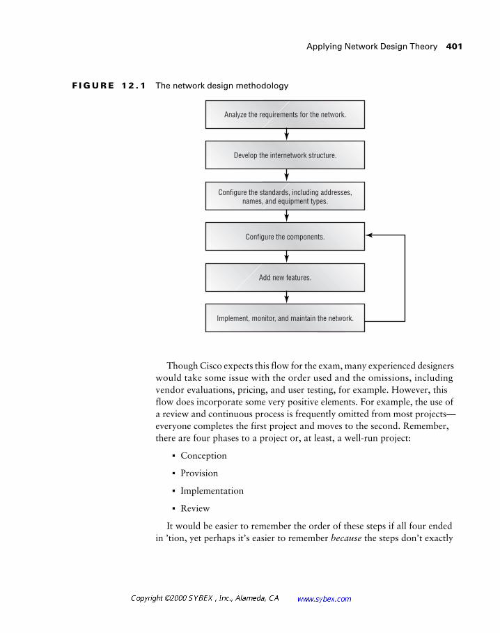
Applying Network Design Theory 401
F I G U R E 1 2 . 1 The network design methodology
Though Cisco expects this flow for the exam, many experienced designers would take some issue with the order used and the omissions, including vendor evaluations, pricing, and user testing, for example. However, this flow does incorporate some very positive elements. For example, the use of a review and continuous process is frequently omitted from most projects—everyone completes the first project and moves to the second. Remember, there are four phases to a project or, at least, a well-run project:
� Conception
� Provision
� Implementation
� Review
It would be easier to remember the order of these steps if all four ended in ’tion, yet perhaps it’s easier to remember because the steps don’t exactly
Analyze the requirements for the network.
Develop the internetwork structure.
Configure the standards, including addresses,names, and equipment types.
Configure the components.
Add new features.
Implement, monitor, and maintain the network.
402 Chapter 12 � Network Design Review
flow together. Another memory aid is to skip the implementation step and think CPR. Many projects require first aid soon after implementation because the review step was dismissed.
The CID model illustrated in Figure 12.1 accomplishes a number of things. The key points to remember are:
� The sequence follows a logical flow from project conception to review.
� The methodology incorporates the critical task of obtaining customer requirements and expectations.
� The concept of standardization is incorporated. This occurs most visibly at the naming and addressing phase.
The Network Design Process
The following recommended network design process incorporates more detail than the model above, but it stops before the implementation and review phases. In fact, it is specifically targeted to the conception and provi-sioning steps, which frequently determine the success of the project.
1. Identify any business constraints on the project or design.
� Document the budget and resources available for this project and establish a time line. Gantt charts, which show the relationships between each task over time and per resource, are very helpful in this phase. All participants in the project should be able to identify the dependencies with other efforts and tasks.
� Identify the staffing requirements, including hiring, training, and contracting. Vendor requirements should also be identified. This step is sometimes appropriate before the equipment is selected; a few thousand dollars spent on a class to see that the equipment is not appropriate for the company is cheap compared to the purchase price. If the company uses the equipment, the expenditure is not wasted.
2. Identify the security requirements for the network.
� Assess the security risks and determine what security will be needed and of what type. As presented in Chapter 11, this process should include physical and logical security against internal and external threats.
Applying Network Design Theory 403
� Determine outside access requirements for data. This may include Web transaction servers and database access; attention should be given to vendor support connectivity as well. Many vendors need remote control or remote node connectivity in order to provide support.
� Identify any requirements for authenticating routes received from access routers or other routers. This task rarely evolves into a sig-nificant issue, but route spoofing and other attacks, such as DNS spoofing, should be considered.
� Determine the authorization and authentication requirements for users, including those in corporate branch offices, mobile users, and telecommuters. VPN technologies and services, including TACACS+ and RADIUS, are important to consider in this phase.
� Identify the requirements for host security, including the physical security of hosts and user accounts. Again, physical security is a foundation to all other protection mechanisms. Consideration should be given to user acceptance of the security model to make certain that they don’t proactively circumvent it.
3. Identify manageability requirements.
� Identify the requirements for fault management, accounting man-agement, configuration management, performance management, and security management. It may also be appropriate to consider change management at this phase. This is an area where many companies falter. Placing a circuit in the network is relatively easy, but failure to consider the support of that circuit can harm even the best design.
4. Extract application requirements.
� Obtain and document the names and types of new applications and the protocols that will be used. Include port numbers where applicable. This phase typically requires repeated efforts, as many applications use administratively defined ports or internally defined ones that are unknown to the system administrators.
� Document the projected number of users who will use the new applications and protocols. This is a key component of scalability and capacity planning.
404 Chapter 12 � Network Design Review
� Diagram the flow of information through the network for new applications. This should be compared to current data-flow diagrams. Again, this is a key component of capacity planning.
� Identify the peak hours of usage of new applications. This infor-mation should be stored in a central location outside of the project so that other groups can anticipate future demands.
5. Characterize new network traffic.
� Characterize the traffic load. This includes many components from the application requirements; however, it needs to include dependencies on other servers and resources.
� Characterize the new application’s traffic behaviors, including broadcast/multicast, supported frame size(s), windowing and flow control, and the error-recovery mechanisms available.
6. Identify any performance requirements and define preliminary design goals. This may include service-level projections such as:
� Application and network response time—two factors in the user experience.
� Network and application availability. If there are high-availability needs, it is likely that redundancy and fault-tolerance efforts will require funding.
� Threshold for network utilization. This may include historical projections and failure scenarios. For example, a network failure (single event) may not affect the application performance by more than a certain amount. Consider two load-balancing circuits and a service level that precludes user impact during a single circuit failure. The user should not see a reduction in response time or throughput when only one circuit is busy. A threshold of no more than 50 percent would be required in order to ensure that packets will be accommodated on the single circuit. Ideally, this number would be reduced to a comfortable level—perhaps 35 to 40 percent when both circuits are operational—that doesn’t saturate the circuit.
Applying Network Design Theory 405
� Data throughput, measured between nodes per unit of time, usu-ally seconds. This accounts for bursts in the network. Most designers will not design for bursts, opting for a five-minute to one-hour average utilization instead. However, if the user saturates the link for five minutes and the link is idle for the remaining 55 minutes, this will lead to poor performance as observed by the user.
� Network latency, which is a minor concern in most networks today. However, carriers should be held to a maximum service-acceptable latency—somewhere between 50 and 85 ms for a cross-country (US) circuit. The routing of the circuit can impact not only latency, but also reliability—it is usually better to have the straightest path as opposed to a circuitous one.
7. Create a customer needs specification document (optional).
� Record the customer’s requirements and constraints and the char-acteristics of the existing network. This type of document is crit-ical to providing a clear review process—did the project meet the objectives?
Some argue that this step is not optional and that it should appear earlier in the process. Experience should provide a guide in your individual environment.
Of course, this list is somewhat utopic. The sad reality is that many of these steps are skipped in the mad rush to deploy new systems. Nonetheless, this is a good list to know for the exam and a wonderful target to strive for in production networks.
Select those items that are most beneficial to your environment and create a form that addresses them. It doesn’t have to be bureaucratic. Rather, use it for your own reference and augment it as necessary.
406 Chapter 12 � Network Design Review
Network Monitoring and Management
As networks grow, it becomes increasingly difficult to monitor and maintain each individual component. At the same time, it’s likely that the critical nature of each component increases to the point where outages can cost millions of dollars.
Network monitoring tools were designed to alert operations staff to real-time problems. Most of these solutions use polling, SNMP (Simple Network Management Protocol), and RMON (Remote Monitoring) to detect changes in the environment, and most incorporate a graphical interface that inter-connects the various devices. Network management expands upon the basic monitoring tools and typically adds configuration and enhanced monitoring capabilities. This may incorporate extended RMON functions, including embedded protocol capture.
For obvious reasons, Cisco champions their CiscoWorks network man-agement suite. This product can work with other platforms, including HP’s OpenView and Sun’s Domain Manager. Like most network management tools, CiscoWorks uses a database to maintain information regarding the network elements. It also provides a number of features, including the following:
� Router and switch configuration tools
� Monitoring of the current network state
� Real-time network analysis
� Historical data collection for trend analysis
Network management tools can also aid in the configuration of the net-work. Programs are available to simplify the establishment of VLANs and other parameters that would otherwise require manual input with the command-line interface. Tools can not only speed up the configuration pro-cess, but they can allow less-trained workers to perform these tasks—they will not have to learn the intricacies of the command-line interface (CLI).
While the network-management tools like CiscoWorks can greatly assist the network administrator, there are other methods that can be used to obtain information regarding the network’s health. These include:
� The command-line interface (CLI)
� The Cisco show and debug commands
� The Cisco ping, telnet, and traceroute commands
Network Monitoring and Management 407
� Protocol analyzers
� Logging, including syslog
Baselining is the act of measuring normal network characteristics under typical conditions. This information is invaluable for capacity planning and can assist in troubleshooting. During configuration or baselining, there are additional resources and tools to consider during a network outage. These resources include:
� DNS and WINS
� TFTP and FTP
� DHCP and BOOTP
� RADIUS and TACACS+
When deploying network-monitoring tools, designers should evaluate the importance of each tier and segment. For example, the core layer likely requires a substantial amount of monitoring in real time, while elements at the access layer will likely have less impact on the overall network than will a problem in the core. Thus, a designer may place RMON probes in the core but use the command line to diagnose problems in remote locations.
In addition, the designer should consider implementing technologies in a manner that augments troubleshooting. This may include:
� An out-of-band management VLAN for switches. Out-of-band con-nections do not traverse the same connections as user data paths, called in-band connections.
� Out-of-band connections to the console or auxiliary port on network devices.
� Terminal servers to connect to all network devices out-of-band.
� The use of hot standby router protocols and other technologies.
� The use of redundant Supervisor engines and power supplies.
� Placement of the network management tool in the core of the network.
� Training of nontechnical staff to provide minimal support in remote locations.
� Documentation of the network, IP addresses, configuration files, and design objectives.
� Configuration of backup servers.
408 Chapter 12 � Network Design Review
Summary
This chapter incorporated a number of concepts regarding the overall network design process and the tools that administrators and designers may use to gain more control over increasingly complex environments. In addi-tion, it highlighted the concepts that are most common in network design as well as the material that typically causes students the most difficulty. Finally, this chapter detailed two design templates that can assist designers new to the network design process.
At this point, readers should feel comfortable with the importance of con-sidering nontechnical aspects of network design as well as the technical. The benefits of project-management methodologies and experience should also be clear.
Review Questions 409
Review Questions
1. Following the implementation phase of a project, the network design-ers should:
A. Review the original project goals against the existing implementation
B. Move on to the next project
C. Take a vacation
D. Run down the hall screaming, “Bad thing!” when the network crashes
2. Which of the following is not true regarding network-management tools?
A. They assist administrators by alerting them to potential network problems.
B. They provide an efficient means of configuring network devices.
C. They replace the need for a good network design.
D. In most cases, they use SNMP and RMON.
3. Following the development of an internetwork structure, the designer should:
A. Configure the network equipment
B. Determine the business needs
C. Configure the network standards, including naming and addressing
D. None of the above
410 Chapter 12 � Network Design Review
4. The first step in a network design project should be:
A. Order the equipment
B. Develop a naming convention
C. Select a vendor
D. Consult with the business
5. The last step in a well-run network design is:
A. Documentation
B. Benchmarking
C. Configuration backup
D. There is no last step. Good network design should incorporate continuous review, although the other three answers are part of this process.
6. Which of the following is a tool that can assist the administrator in monitoring the network?
A. CiscoWorks
B. HP OpenView
C. Sun Domain Manager
D. All of the above
7. In a dual-circuit load-balancing configuration, at what point should the capacity of a single circuit be increased so that a single circuit failure does not impact the user?
A. 10 percent
B. 40 percent
C. 80 percent
D. 100 percent

Review Questions 411
8. Manageability is a step in the network-design process. True or false?
A. True
B. False
9. The cost of one hour’s downtime, based on 100 employees impacted at an average rate of $60 per hour, would be roughly how much, presuming a 100 percent reliance on computer systems and a noncustomer-facing environment?
A. Nothing
B. Less than $1000
C. Around $6000
D. More than $500,000
10. A well-run project should have which of the following?
A. Conception, Implementation, and Diagnostic phases
B. Weekly status meetings and monthly parties
C. Conception, Provision, Implementation, and Review phases
D. None of the above

412 Chapter 12 � Network Design Review
Answers to Review Questions
1. A.
2. C.
3. C.
4. D.
5. D.
6. D.
7. B.
8. A.
9. C.
10. C.
A number of modern network design concepts do not fit within the framework of the CID exam objectives. While this book has incorporated some of these issues in the main text—Digital Subscriber Line (DSL) and on-demand routing (ODR), for example—there are other subjects that are best covered in an isolated chapter.
Therefore, this chapter will cover some of these other issues that confront modern network designers, including:
� IP multicast
� Redundancy
� Layer 2 and Layer 3 design
� Troubleshooting
� The Internet
� Wireless
� Case management
� Trend analysis and capacity planning
� Encryption
� The future of networking
The bulk of this chapter incorporates concepts that are not part of the Cisco exam objectives, and so readers are encouraged only to review this material. Some specific attention should be given to IP multicast, however.
IP Multicast 415
IP Multicast
As the need for one-to-many communications increased, developers realized that the traditional unicast and broadcast would be unable to scale and accommodate the demand. A method to transmit a single packet and forward that packet to multiple receivers on a dynamic basis was needed.
IP multicast accomplishes precisely this function. Clients inform the net-work that they wish to receive a data stream. This is analogous to tuning a television. However, the multicast does not specify a certain channel. Rather, it sends a datagram with a specific IP address from the Class D block, which ranges from 224.0.0.0 to 239.255.255.255. Note that there are well-known multicast addresses that are used by some protocols, including HSRP and EIGRP—this section is more concerned with multicasts that traverse routers. All stations in the multicast group will use an address from this block to join and receive the data flow. It is interesting to note that the MAC address for these IP addresses is also defined in the protocol (RFC 1112). The first three octets are 01:00:5E, and the last 23 bits are defined from the last three octets of the multicast IP address. For example, multicast group 227.4.5.6 will use MAC address 01:00:5E:04:05:06, with the remaining bit (high order in the fourth octet) always set to 0.
Designers should refer to RFC 1469 for information regarding Token Ring multicast.
Once the client joins the multicast, the routers are responsible for permit-ting the data flow to move from the server to the end station. This prevents the multicast from forwarding onto segments that do not wish to participate. In addition, the workstation can use the multicast address to determine whether it wishes to receive the multicast at Layer 2. For non-recipient stations on the same segment, this eliminates unnecessary interrupts. Figure 13.1 illus-trates a typical multicast network. Only those routers that need to forward the multicast out an interface receive the data stream. The thicker lines and black serial connection indicate this arrangement. The white serial connec-tions and the thin lines denote a pruned connection—the multicast is not forwarded on these links, which ultimately conserves bandwidth. Pruning, like trimming the branches on a tree, infers that the path from the trunk to the leaves has been cut.
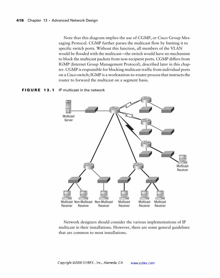
416 Chapter 13 � Advanced Network Design
Note that this diagram implies the use of CGMP, or Cisco Group Mes-saging Protocol. CGMP further parses the multicast flow by limiting it to specific switch ports. Without this function, all members of the VLAN would be flooded with the multicast—the switch would have no mechanism to block the multicast packets from non-recipient ports. CGMP differs from IGMP (Internet Group Management Protocol), described later in this chap-ter. CGMP is responsible for blocking multicast traffic from individual ports on a Cisco switch; IGMP is a workstation-to-router process that instructs the router to forward the multicast on a segment basis.
F I G U R E 1 3 . 1 IP multicast in the network
Network designers should consider the various implementations of IP multicast in their installations. However, there are some general guidelines that are common to most installations.
MulticastReceiver
Non-MulticastReceiver
Non-MulticastReceiver
MulticastReceiver
MulticastReceiver
MulticastReceiver
MulticastReceiver
MulticastServer
IP Multicast 417
First, multicast clients request to join the multicast via an IGMP request to their local router. The primary rational behind this mechanism is to keep multicast traffic from forwarding onto a segment—allowing the segment to be pruned. Note that IGMP is a Layer 3 protocol, operating at the same layer as IP or ICMP.
Second, designers will need to select a multicast protocol that operates between the routers in the network. PIM (Protocol Independent Multicast) is typically found in many deployments. However, DVMRP (Distance Vec-tor Multicast Routing Protocol) is also available. DVMRP is usually found in installations that connect the MBONE, or the Internet’s multicast back-bone. Cisco’s implementation of DVMRP is incomplete, depending on the IOS (Internet Operating System) version, and so most installations use PIM.
PIM operates in three modes on Cisco routers: dense mode, sparse mode, and sparse-dense mode. Functionally, each of these modes works to control the multicast tree; however, sparse mode uses a rendezvous point (RP). Dense mode is very similar to DVMRP—both protocols assume that band-width is not a factor and that all routers wish to join the multicast. Sparse mode indicates that the routers are farther apart (sparsely populated) and that bandwidth is typically constrained. This situation is common in WAN environments; however, sparse mode may be used in LANs as well.
Sparse-mode protocols operate under the premise that each router must explicitly join the multicast. In this design, each source transmits its multi-cast along the shortest path to the RP, which distributes the packet to regis-tered receivers.
It is important to note that PIM relies on an underlying unicast routing protocol regardless of configuration for sparse or dense mode. In addition, each multicast group should contain a single rendezvous point. Sparse mode uses a process called shortest path switchover to join and leave the multicast tree, which conserves bandwidth.
As noted previously, PIM also operates in sparse-dense mode on Cisco routers. In this configuration, the router will first operate in sparse mode and will then convert to dense-mode operation if a problem arises. Such a problem typically involves failure of the RP. Therefore, Cisco recommends the use of sparse-dense mode for all large-scale multicast deployments. These types of installation typically involve low-bandwidth or geographically distant links and require some degree of redundancy. Designers should note that the RP can be located via two dynamic methods—auto-RP and candidate-RP announcements. In addition, every router in the multicast group can be con-figured with a static entry for the RP.
418 Chapter 13 � Advanced Network Design
The multicast routing protocols are designed primarily to avoid forward-ing loops. Consider a generic rule that states that all multicasts are for-warded out all interfaces except the source interface. This method works fine for simple linear topologies. However, it is easy to understand that a loop would occur if the topology provided additional paths. For example, router A forwards to B, which forwards to C, which returns the packet to A.
DVMRP and PIM both operate to prevent looping from occurring by understanding the network topology and using Reverse Path Forwarding (RPF). This mechanism uses the distance back to the multicast source and effectively creates a spanning tree to control the flow of the multicast packets. RPF is not part of the 802.1d specification but operates as part of a Layer 3 process on the routers participating in the multicast.
Catalyst switches offer the ability to squelch broadcasts and multicasts at a predefined threshold based on per-second monitoring. Designers should use this feature with care as the deployment of multicasts may exceed this setting.
Multicast will be an important component in the deployment of voice, video, and data services. As part of its Architecture of Voice, Video and Inte-grated Data (AVVID) initiative, Cisco announced new multimedia applica-tions that will provide video services to the desktop. In addition to the IP/TV offering, Cisco will release IP/VC in early 2000. These products build upon H.323 and other standards to provide compression of the data stream and encoding. Administrators may wish to evaluate the IP/VC product, which promises to operate with the Windows Media Player—a benefit that may preclude the installation of new software at every workstation.
Design Considerations for Quality of Service
Most vendors champion their QoS, or quality of service, offerings as a value added into the network. This set of features was a primary motivator for the migration to ATM in the mid-1990s. A second method, RSVP, or the Resource Reservation Protocol, was also developed to provide guaranteed bandwidth.
Redundancy and Load Balancing 419
At present, QoS simply refers to the ability of the network to reserve bandwidth for the application data stream. For example, a program may query the network to obtain 1Mbps of available bandwidth that cannot be impacted. Doing so provides the application with quality service—per-formance is not degraded for the requesting application because it has reserved all the bandwidth it should need. All other applications are left to contend for the remaining bandwidth.
Under most circumstances, QoS is a factor only when bandwidth is lim-ited. Most designers opt to provide additional bandwidth under the premise that no single application warrants more access to the network than another. Of course, in some instances, it is appropriate to reserve bandwidth. A typical situation would be for real-time data, including voice and video.
It is important for designers to note that RSVP is not a routing protocol. Rather, RSVP operates at the transport layer and is used to establish QoS over an existing routed path.
Designers planning to implement enterprise-wide multicast services or real-time data services should review and evaluate the QoS features available to them.
Redundancy and Load Balancing
One of the simplest redundancy options available to network design-ers is the Cisco proprietary HSRP, or Hot Standby Router Protocol. HSRP configurations establish two router interfaces on the local subnet and dupli-cate the MAC address and the IP address on each router. This duplication is permitted because only one HSRP interface is active at any time. Each inter-face also has its original IP address and MAC address. This configuration is illustrated in Figure 13.2, which shows the left router as the HSRP primary and the right router as the HSRP secondary.
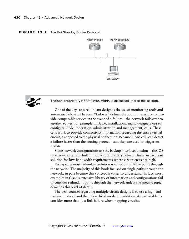
420 Chapter 13 � Advanced Network Design
F I G U R E 1 3 . 2 The Hot Standby Router Protocol
The non-proprietary HSRP flavor, VRRP, is discussed later in this section.
One of the keys to a redundant design is the use of monitoring tools and automatic failover. The term “failover” defines the actions necessary to pro-vide comparable service in the event of a failure—the network fails over to another router, for example. In ATM installations, many designers opt to configure OAM (operation, administration and management) cells. These cells work to provide connectivity information regarding the entire virtual circuit, as opposed to the physical connection. Because OAM cells can detect a failure faster than the routing protocol can, they are used to trigger an update.
Some network configurations use the backup interface function in the IOS to activate a standby link in the event of primary failure. This is an excellent solution for low-bandwidth requirements where circuit costs are high.
Perhaps the most redundant solution is to install multiple paths through the network. The majority of this book focused on single paths through the network, in part because this concept is easier to understand. In fact, most examples in Cisco’s extensive library of information and configurations fail to consider redundant paths through the network unless the specific topic demands this level of detail.
The best counsel regarding multiple circuit designs is to use a high-end routing protocol and the hierarchical model. In addition, it is advisable to consider more than just link failure when mapping circuits.
HSRP Primary HSRP Secondary
Workstation
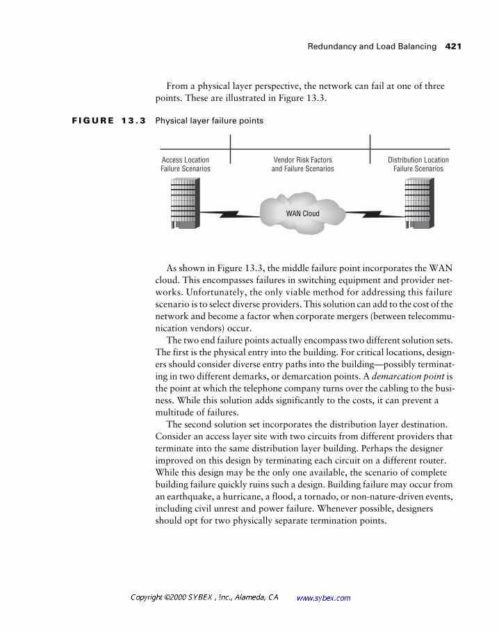
Redundancy and Load Balancing 421
From a physical layer perspective, the network can fail at one of three points. These are illustrated in Figure 13.3.
F I G U R E 1 3 . 3 Physical layer failure points
As shown in Figure 13.3, the middle failure point incorporates the WAN cloud. This encompasses failures in switching equipment and provider net-works. Unfortunately, the only viable method for addressing this failure scenario is to select diverse providers. This solution can add to the cost of the network and become a factor when corporate mergers (between telecommu-nication vendors) occur.
The two end failure points actually encompass two different solution sets. The first is the physical entry into the building. For critical locations, design-ers should consider diverse entry paths into the building—possibly terminat-ing in two different demarks, or demarcation points. A demarcation point is the point at which the telephone company turns over the cabling to the busi-ness. While this solution adds significantly to the costs, it can prevent a multitude of failures.
The second solution set incorporates the distribution layer destination. Consider an access layer site with two circuits from different providers that terminate into the same distribution layer building. Perhaps the designer improved on this design by terminating each circuit on a different router. While this design may be the only one available, the scenario of complete building failure quickly ruins such a design. Building failure may occur from an earthquake, a hurricane, a flood, a tornado, or non-nature-driven events, including civil unrest and power failure. Whenever possible, designers should opt for two physically separate termination points.
WAN Cloud
Access LocationFailure Scenarios
Distribution LocationFailure Scenarios
Vendor Risk Factorsand Failure Scenarios
422 Chapter 13 � Advanced Network Design
Virtual Router Redundancy Protocol
Cisco released its proprietary HSRP in 1994, which greatly enhanced the options available to designers in regards to redundancy. With the added tracking feature, which adjusts the HSRP priorities based on the status of another interface, HSRP was capable of addressing router and link failures in specific scenarios. While HSRP was not without limitations—not the least of which was its proprietary nature—many Cisco-centric designs made use of this service.
As of this writing, a number of vendors are adding the non-proprietary Virtual Router Redundancy Protocol, or VRRP, to their products. Cisco has agreed to support this protocol alongside HSRP, which should provide many options for the network architect. As defined in RFC 2338, VRRP provides similar functions to HSRP.
One of the primary benefits availed by VRRP, in addition to its multi-vendor support, is ICMP (Internet Control Message Protocol) redirect. The ICMP redirect feature allows a default gateway to teach a workstation about an alternative router that is better suited to send packets to the destination. While Cisco has announced that this feature will be added to HSRP, its absence has led to a number of limitations for designers in asymmetric routing configurations—instances where the two routers servicing the segment have widely diverse remote paths.
Layer 2 versus Layer 3 Design
The issue of Layer 2 versus Layer 3 design appeared in a few sections of this text; however, the majority of the CID material and exam objectives view Layer 2 solutions as the only ones available. This attitude will be changed with the next revision of the course materials and exam.
For years, vendors pushed customers to leave the slow, difficult-to-configure, routed world in favor of flat, switched networks. This trend has effectively reversed itself—primarily as a result of “wire–speed” Layer 3 awareness.
As a result, switches with Layer 3, 4, and 5 awareness are becoming quite functional and necessary in order to facilitate the designs that are now in vogue. Typically, networks are required to address a high volume of off-network traffic. Specialty segments for databases, Web servers, and e-mail
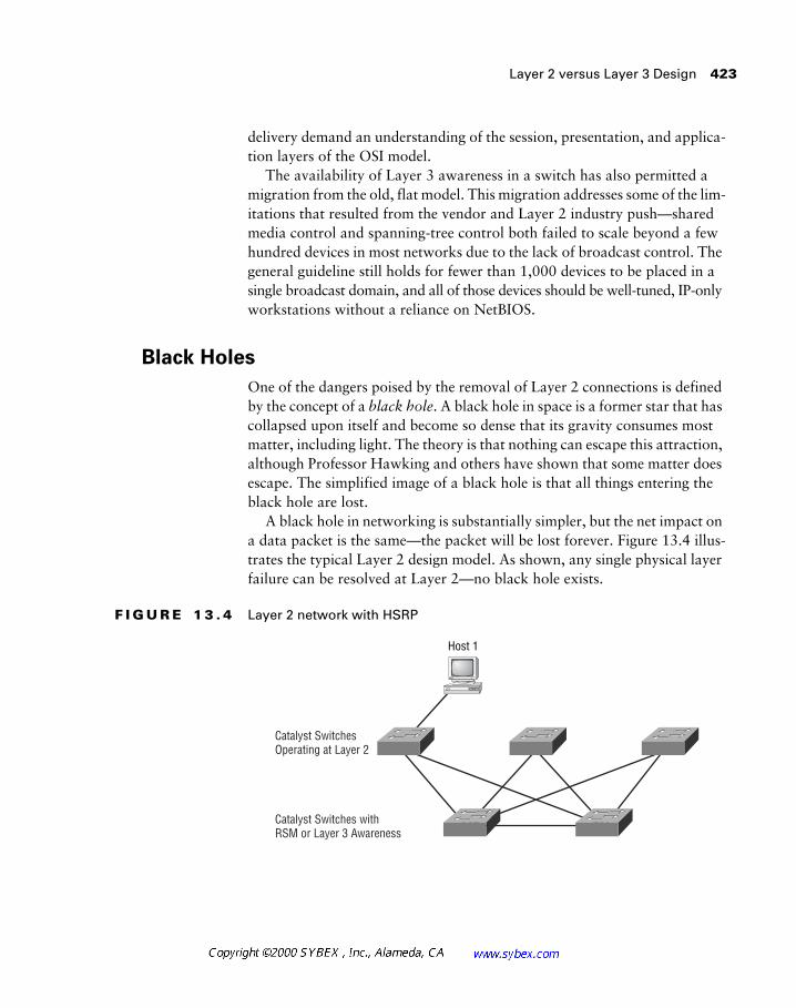
Layer 2 versus Layer 3 Design 423
delivery demand an understanding of the session, presentation, and applica-tion layers of the OSI model.
The availability of Layer 3 awareness in a switch has also permitted a migration from the old, flat model. This migration addresses some of the lim-itations that resulted from the vendor and Layer 2 industry push—shared media control and spanning-tree control both failed to scale beyond a few hundred devices in most networks due to the lack of broadcast control. The general guideline still holds for fewer than 1,000 devices to be placed in a single broadcast domain, and all of those devices should be well-tuned, IP-only workstations without a reliance on NetBIOS.
Black Holes
One of the dangers poised by the removal of Layer 2 connections is defined by the concept of a black hole. A black hole in space is a former star that has collapsed upon itself and become so dense that its gravity consumes most matter, including light. The theory is that nothing can escape this attraction, although Professor Hawking and others have shown that some matter does escape. The simplified image of a black hole is that all things entering the black hole are lost.
A black hole in networking is substantially simpler, but the net impact on a data packet is the same—the packet will be lost forever. Figure 13.4 illus-trates the typical Layer 2 design model. As shown, any single physical layer failure can be resolved at Layer 2—no black hole exists.
F I G U R E 1 3 . 4 Layer 2 network with HSRP
Catalyst Switches Operating at Layer 2
Catalyst Switches with RSM or Layer 3 Awareness
Host 1
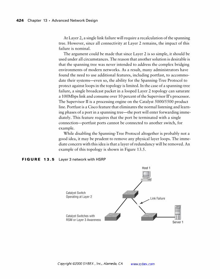
424 Chapter 13 � Advanced Network Design
At Layer 2, a single link failure will require a recalculation of the spanning tree. However, since all connectivity at Layer 2 remains, the impact of this failure is nominal.
The argument could be made that since Layer 2 is so simple, it should be used under all circumstances. The reason that another solution is desirable is that the spanning tree was never intended to address the complex bridging environments of modern networks. As a result, many administrators have found the need to use additional features, including portfast, to accommo-date their systems—even so, the ability for the Spanning-Tree Protocol to protect against loops in the topology is limited. In the case of a spanning-tree failure, a single broadcast packet in a looped Layer 2 topology can saturate a 100Mbps link and consume over 10 percent of the Supervisor II’s processor. The Supervisor II is a processing engine on the Catalyst 5000/5500 product line. Portfast is a Cisco feature that eliminates the normal listening and learn-ing phases of a port in a spanning tree—the port will enter forwarding imme-diately. This feature requires that the port be terminated with a single connection—portfast ports cannot be connected to another switch, for example.
While disabling the Spanning-Tree Protocol altogether is probably not a good idea, it may be prudent to remove any physical layer loops. The imme-diate concern with this idea is that a layer of redundancy will be removed. An example of this topology is shown in Figure 13.5.
F I G U R E 1 3 . 5 Layer 3 network with HSRP
Catalyst Switch Operating at Layer 2
Catalyst Switches with RSM or Layer 3 Awareness
Link Failure
Host 1
Server 1
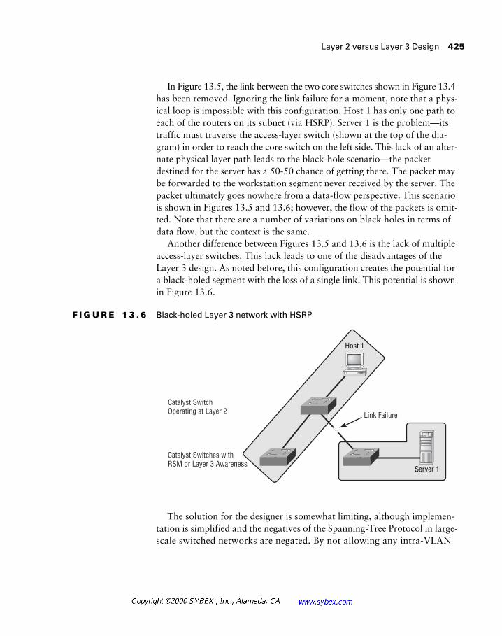
Layer 2 versus Layer 3 Design 425
In Figure 13.5, the link between the two core switches shown in Figure 13.4 has been removed. Ignoring the link failure for a moment, note that a phys-ical loop is impossible with this configuration. Host 1 has only one path to each of the routers on its subnet (via HSRP). Server 1 is the problem—its traffic must traverse the access-layer switch (shown at the top of the dia-gram) in order to reach the core switch on the left side. This lack of an alter-nate physical layer path leads to the black-hole scenario—the packet destined for the server has a 50-50 chance of getting there. The packet may be forwarded to the workstation segment never received by the server. The packet ultimately goes nowhere from a data-flow perspective. This scenario is shown in Figures 13.5 and 13.6; however, the flow of the packets is omit-ted. Note that there are a number of variations on black holes in terms of data flow, but the context is the same.
Another difference between Figures 13.5 and 13.6 is the lack of multiple access-layer switches. This lack leads to one of the disadvantages of the Layer 3 design. As noted before, this configuration creates the potential for a black-holed segment with the loss of a single link. This potential is shown in Figure 13.6.
F I G U R E 1 3 . 6 Black-holed Layer 3 network with HSRP
The solution for the designer is somewhat limiting, although implemen-tation is simplified and the negatives of the Spanning-Tree Protocol in large-scale switched networks are negated. By not allowing any intra-VLAN
Catalyst Switch Operating at Layer 2
Catalyst Switches with RSM or Layer 3 Awareness
Link Failure
Host 1
Server 1
426 Chapter 13 � Advanced Network Design
connections except the feed links and the access-layer switch, the designer may use HSRP or VRRP to provide redundancy and a loop-free configura-tion. This design admittedly removes some of the advantages of VLANs—the network is again highly reliant upon Layer 3, but that is acceptable in modern design. With Layer 3 awareness at wire speeds, any performance dis-advantages are virtually negated and the benefits of broadcast control are added.
Troubleshooting as a Design Consideration
Previous chapters touched upon the concept of troubleshooting as a design consideration, but it certainly warrants additional space. Many designers omit this crucial step in developing their designs.
Consider a fairly simple need in the operation of a network—change win-dows and outages. These concepts address the fact that changes will be needed in the network in order to meet evolving business needs. However, these changes may conflict with uptime requirements of another business application.
The network architect can plan for these issues with a thorough under-standing of the business and a well-planned outage schedule. Perhaps the backup system requires connectivity to the mainframe in order to operate. The designer can use this information to isolate this system from the rest of the installation. When the mainframe technicians schedule an IPL (Initial Program Load), the backup system and the network can be repaired and upgraded as well—users cannot access the down system, making this a log-ical window for troubleshooting. Using this tactic, the entire network can be mapped to provide the best upgrade schedule with the minimum overlap.
Internet Network Design
No computing book today would be complete without a section on the Internet. Perhaps no other single event has so quickly combined the tech-nical and nontechnical worlds, and as presented in Chapter 11and embel-lished here, perhaps nothing is more important to the successful use of the Internet than security.
Internet Network Design 427
The importance of linking business needs to the technology available has been presented throughout this text. This is especially true for the Internet, although unique issues arise when planning for this medium.
The scope of Internet connectivity in companies today ranges from basic e-mail services through multi-homed, e-commerce solutions. Each of these connections requires different levels of security, access, performance, and technical skill to operate successfully.
Designers typically focus on the security aspects of Internet connectivity, and while this is a significant area of concern, it is an incomplete attitude. Installing a firewall does not encompass a security solution.
A recent successful hacking event, an event made possible by a ZDNet publication using a specially established network, made use of a minor CGI (Common Gateway Interface) bug and knowledge of Unix to completely bypass the company’s firewall and the front-end access lists. The attack was really performed at the application layer—the routers and firewalls were not attacked or disabled in order to grant the hacker access to the server. This attack resulted in only a modified home page on a Web server; however, in other installations, the damage could have easily included corrupted data-base files and the loss of market share resulting from the bad publicity. The issue, as a Cisco employee states, is not whether you’re paranoid, but rather whether you’re paranoid enough. It is easy to take this attitude to an extreme—the reality is that attacks on corporate data can occur even with-out access to the Internet. Consider the impact on the company when the CFO’s notebook containing all the financial data and strategic plans for the corporation is stolen. It happens.
For the network designer, it is impractical to think that the network can provide all the security necessary for a corporation, including its Internet connectivity. Too many additional factors must work together in order to achieve security. However, the network design can work to augment an overall security plan. Consider the following factors in your designs:
� Every security mechanism must be auditable by a third party.
� Access lists can provide a good front-line defense, but attention should also be given to network performance.
� Firewalls and bastion hosts certainly help to provide data security, but they must be well understood by administrators.
428 Chapter 13 � Advanced Network Design
� Depending on the reference cited, up to 90 percent of attacks origi-nate from inside the network, effectively bypassing most firewall installations.
� Auditing is perhaps the single most important function of a network security solution.
� Designers and administrators should attack their own networks with the knowledge of management. It is even better to have cooperative tests with another organization or with a third party.
� Network administrators must stay informed on the latest patches, programs, and attack methodologies.
� Designers must secure SNMP on every device in the network.
In addition to the network processes, designers should work with admin-istration and other departments to provide the best security solution. This will frequently include scanning for viruses, controlling passwords, and using diskless workstations and encryption.
Companies frequently rush to deploy new services for customers that may compromise the best security models. One of these services is the self-service kiosk, a terminal that is available to customers in a business office or remote location. These devices frequently compare with automated teller machines, although their functionality is often much greater. They can pose a sub-stantial security threat when placed on the same network as the corporate workers—an event that occurs regularly. Most companies rely on physical security to protect their computer systems—it should be difficult to walk into an organization and start entering data on a networked computer. Con-sider the impact of a hacker using a locally connected machine to launch an attack or placing a protocol analyzer on the segment—passwords and other data could easily be compromised. Another risk is the potential for questionable material to be loaded onto the kiosk machine—an adult Web site, for example. The public relations impact of this prank alone could be very dam-aging to the company.
The kiosk concept makes such attacks even simpler. Many companies have rushed to deploy these solutions and have used the standard work-station software image (software configuration loaded to all machines in the enterprise)—the one with the populated hosts file—in deployment. As noted previously, some companies have even placed these stations on the same net-work segment as regular production traffic with no security whatsoever.
Wireless Network Design 429
Fortunately, the majority of readers already realize just how dangerous this design can be. It thus becomes the job of the designer to understand the busi-ness needs and then educate the business on the risks that it is facing.
Wireless Network Design
A number of wireless solutions are available to the network designer, including those based on the 802.11 standard. These solutions range from infrared links with handheld devices and notebooks all the way to OC-3-capable laser and microwave solutions.
At the low end, the network designer typically does not consider infrared links and other low-bandwidth solutions as part of the design. Usually, these services are deployed at the workgroup level.
At mid-tier, the network designer may use wireless solutions that include PCS (personal communications system—similar to but different than cellular), cellular, and radio. The network architect will frequently need to provide connectivity and security in these installations. In many corporations, these solutions are deployed in isolated networks that do not involve the produc-tion network. However, administrators are well advised to get involved early in these projects—ultimately these networks may connect to the primary network.
At the high end of wireless services are satellite, laser, and microwave. These solutions frequently connect entire networks and require the involve-ment of the network designer.
Satellite services are typically deployed to address two possible needs. The first involves the availability of cable-based installations—many countries are cursed with the theft of copper cables. Stories are rampant about circuits that have mysteriously failed. Upon dispatch, the vendors have learned that miles of copper cable have been cut and removed from the poles.
The second satellite installation usually involves mobile stations, includ-ing ships. These networks link shipboard computers with monitoring sta-tions that use real-time data to schedule maintenance and provide communications. While the biggest negative to satellite communications is cost, the designer should also consider link delay.
Laser and microwave installations are excellent short-range solutions. Each avoids the need to trench or pull cable in order to connect two net-works, and the reliability of these solutions has increased substantially.
430 Chapter 13 � Advanced Network Design
Designers should consider reliability and distance when evaluating these options. The cost savings can be substantial, as there is only a one-time charge for the initial hardware purchase and there are no ongoing leased-line fees to pay.
Advances in wireless technology will likely improve wireless coverage and reduce the costs of these solutions.
Case Management
Most network managers and directors will point to documentation of the network as a key concern and trouble area. Another concern is case management.
Case management is a concept similar to trouble-ticket tracking, but it incorporates a broader scope. Many companies use trouble tickets to record problems called into the help desk or service center. Trouble-ticket tracking is the act of reviewing these tickets to improve customer service. Cisco pro-vides an excellent example of case management that starts with the Cisco Connection Online Web site (CCO), located at www.cisco.com. Customers may reference trouble tickets and manually locate patch files and software images without the intervention of the TAC, or Cisco’s technical assistance center. Should the customer find it necessary to speak to a staff member for problem resolution, the Web-based trouble ticket can automatically generate the request.
It is important to note that case management is more than just a ticket-tracking system. It is a philosophy that must incorporate ownership of the problems and, as Cisco has proven, admission of problems to customers in a timely fashion. Few other companies have been as brave in documenting their bugs and other problems as Cisco—few have been as successful in resolving them as well. In addition, Cisco surveys every customer and expects each technician to earn the highest satisfaction scores on every case. This acceptance of nothing less than the best has earned the company numer-ous distinctions.
Network design can augment the case-management process. As noted in Chapter 7, the use of naming conventions can greatly simplify the trouble-shooting process. By linking machine names, IP addresses, and other net-work information to the ticketing system, a single call could generate a note to all other call takers (and ultimately an automated system) that documents
Trend Analysis and Capacity Planning 431
the possibility of a larger failure. This can easily shorten the diagnostic pro-cess since administrators are focused on a single problem instead of looking at each call as an isolated issue.
Many organizations are also providing real-time network data to end users, or at least small groups of end users. This preemptive measure can greatly reduce the number of calls reporting a network capacity problem (described in the next section) because the user can see that a link is operating at only five percent—thus showing that the problem is likely not caused by excessive utilization. While this does not exonerate the network, it does squelch the call to immediately upgrade the circuit. By providing this infor-mation, the designers and architect can initiate a stronger dialog with their users.
Trend Analysis and Capacity Planning
I was recently asked during an interview how I do trend analysis and capacity planning. I answered respectfully that I could provide two answers—the textbook response or the “real-world” truth. I passed over the question without further comment and accepted the position.
The sad truth is that many organizations haven’t the time or expertise to perform an accurate analysis of their network resources. Numerous prod-ucts, including CiscoWorks and Concord Network Health, can greatly sim-plify the data-collection process, but at some point the designer needs to understand the specific utilization on a circuit in order to determine if addi-tional capacity is warranted.
You may wonder what could possibly be analyzed when the circuit is run-ning at 100 percent capacity. However, as an architect, you need to under-stand why traffic rates are so high and to ascertain if this growth was part of the original analysis. Frequently, designers will learn with research that a 256Kbps circuit is supporting unnecessary Web browsing or another optional traffic flow—sometime these unnecessary data flows can consume 75 percent or more of a circuit.
432 Chapter 13 � Advanced Network Design
While each organization is different, the last three audits performed by my team (for two different organizations) showed that over 80 percent of the uti-lization was for stock quotes, sports scores, and other non-business-related material on the circuit. Each company must define acceptable business use, but when utilization is unrelated to the business, it becomes difficult to ignore the associated expense.
Designers must become increasingly vigilant for the bandwidth trap—the addition of more and more bandwidth. This consideration will become increasingly important as the associated costs increase. Increasing costs are due to the fundamental limitations of WAN technology—high recurring costs and high latency (compared to local data stores and cached data). Of course, some organizations, including the government and the sciences, must transfer huge amounts of data daily. Business also may need to send large databases and other files, but compression and other techniques may provide a solution. Recently, a number of financial institutions audited their Web sites and reduced the size of their graphics files to accommodate their cus-tomers. Users of low-speed links immediately appreciated the effort, and lit-tle content was lost. Most important, however, the change extended the length of time that the current bandwidth capacity will continue to meet their needs. Historically, bandwidth demands have required a doubling of capacity every 6 to 12 months in this market.
Capacity planning is possible, and there are general easily implemented rules. For example, a redundant serial connection would likely require attention and expansion once the individual link utilization reaches 35 percent—allowing for sufficient bandwidth upon a single link failure.
Encryption
For the network designer, the issue of encryption has taken on greater importance in the late 1990s. Virtual private networks and business-to-business transactions, both of which may use the Internet for transport, can
Encryption 433
greatly benefit from encryption services. As discussed in Chapters 9 and 11, encryption is the act of scrambling data between the two endpoints in an effort to prevent interception of the data. Encryption may also be used to guarantee the authenticity of the data.
In addition to the wide area networking benefits of encryption, there may be instances when it is desirable to protect data flows in the internal net-work. Telnet, by its very nature, is completely insecure. Data is carried in clear text, resulting in flows that can be intercepted and read with ease. This is of particular concern when you consider the information commonly sent by administrators via Telnet—router logins and configuration files. Even with the benefits of switching, which can hide some of the data flows by only forwarding packets to genuine destinations, it is remarkably easy for an internal source to monitor the traffic destined for a router. The risk increases when Telnet is used for servers and other data-storage devices.
SNMP is another directly related protocol where the network compo-nents are placed at risk within the internal network. Like Telnet, SNMP (dis-regarding Version 3) has a very simple password mechanism, and it sends data in clear text. These two areas should be of some concern to the network administrator, as these security holes could be exploited to initiate a denial-of-service attack or cause other problems that impede the proper flow of business data through the network.
One solution to this problem is SSH, or secure shell. Using SSH coupled with a terminal server, the designer could augment a security model by deny-ing Telnet via the network and providing access only via the console port. This adds some expense, but again, the expense may be justified.
Cisco recently added secure shell services to the IOS, which provides another solution.
Another tool at the designer’s disposal outside the context of encryption is providing access lists to block the IP addresses permitted to access the SNMP ports on the network devices. This makes hacking of the password somewhat moot, as the attacker would also need to hijack the IP address—a more detectible event.
Why include Telnet and SNMP in a section regarding encryption? As noted before, SSH is one alternative to Telnet that uses encryption, and SNMP Version 3 supports a slightly higher level of security than Version 2.
434 Chapter 13 � Advanced Network Design
However, the real connection between these seemingly non-related issues is two-fold.
First, designers need to realize that encryption is not the magic bullet of a security solution. Configuring a router (or front-end device) to provide encryption services does precisely that—it provides encryption services. Failure to secure non-encryption services like Telnet will allow simple attacks that ultimately could thwart the encryption stream.
The second factor in encryption is the selection of an encryption protocol. Rather than describe and define all the current solutions, of which there are many, it is easier to leave this topic to other texts and, more importantly, to vendor relationships. Corporations, like people, make many decisions based on nontechnical factors, which is natural and somewhat unavoidable. As a result, the selection of an encryption provider may be determined through familiarity with a certain vendor or previous solutions. For example, Nortel may provide a better VPN solution, but previous experience with Cisco’s routers and the PIX may lead to a decision to use a Cisco device. Of course, the converse may also be true—Cisco may have a better solution for the organization, but having a shop full of Bay/Nortel routers may make the organization want to stay with such a solution.
Therefore, the best recommendations will likely result from a focus on asking the right questions and looking for standards-based support. Differ-ent protocols encrypt different portions of the packet, which may impact interoperability or diagnostic characteristics. Of course, greater encryption may augment security.
The Future of Network Design
The majority of this text addressed some of the more basic concerns in network design. In reality, future designs will prove to be much more diffi-cult for designers to implement, relative to today, depending on whom you ask. Today, most designers are concerned with connecting workstations to servers and mainframes, and while remote access, wireless, and video-conferencing are all portions of the modern network, the current focus is on a fairly simple model wherein a relatively small number of devices commu-nicate over clusters of networks that loosely interconnect.
In the future, the network will substantially increase in complexity. For example, not only will data require secure connections, but it will also
The Future of Network Design 435
demand true location transparency. In addition, automated data gathering, storage, and manipulation will become increasingly important, according to most futurists.
Consider the evolution of the computer. In a fairly small amount of time, computers have been deployed in many U.S. classrooms with Internet con-nectivity. When considered against the fact that most U.S. schools do not have per-room telephone service, this accomplishment is even more amazing.
Throughout this text, the term “Internet” has been used to mean the Internet that evolved from ARPANET—also called Internet One (I One). No dialog on the future of networking would be complete without noting the efforts in place to establish better networks dedicated to specific tasks, including academic research. However, the use of the term “Internet” does not encompass the Internet Two (I2) project or any of the other new networks.
In the academic arena, engineers and technologists are using systems that may ultimately drive the need for a capacity of over 5Gbps per user. These systems include components beyond virtual reality, wherein individuals relate with each other via sensors and feedback pressure suits. It is conceivable, according to some futurists, that the holodeck from Star Trek will be a reality within 50 years—the technology of today already mimics significant components of science fiction.
It will be interesting to see exactly what network services become com-monplace in society. Today, many people carry cellular phones, PDAs (per-sonal digital assistants), pagers, and watches; there is little reason not to combine all of these devices into a single unit. At present, most users con-tinue to carry multiple devices for historical, user-interface, power, or avail-ability reasons.
Consider the following scenario: What would happen if all such devices automatically communicated with each other? The demands on the network become fairly clear. For this example, consider that no fundamental changes have occurred from a business or humanistic perspective.
Let’s say I received an e-mail message informing me that a friend is flying into the local airport at noon. I received the message at 10 a.m., and I’ve just gone to a meeting.
What if the network allowed a parser (a program that scans text) in my e-mail application to identify this message as being important—beyond the scope of urgent used today. The application could connect to my PDA over
436 Chapter 13 � Advanced Network Design
a wireless link and determine that I had just entered a meeting. Rather than disturbing me, the application could also determine that I had no plans for lunch. The application could send a response to my friend noting that I was unavailable to confirm, but that I would tentatively agree to lunch. Another application could propose three restaurants in the area.
My friend would respond to the e-mail and note that the $100-hamburger place at the airport was fine (ask a pilot if you don’t get the reference). My calendar (possibly as part of my PDA) would automatically receive the update and, when my meeting was over, pop up a confirmation. An appli-cation could also automatically make a reservation at the restaurant, again over the network.
Notice how much of this exchange relied on the application layer and not the network. However, the applications required complete interconnectivity between devices—wireline and wireless—in order to complete the process.
It is likely that the majority of the hurdles in the foreseeable future will be based in Layer 8—politics. Even the end-user financial issues will pale in comparison, according to many researchers. As the model migrates toward services rather than transport, network designers will likely need to concern themselves less with the minutiae of packet flows and more with the interop-erability of the services themselves. Stated another way, the challenge will be to explain and address corporate needs in nontechnical ways while also understanding the interoperability of the applications and their individual links. Billing for packets, for example, may become one of many new areas that require attention from the designer.
Few would argue that the computer revolution has just begun. There are legitimate concerns regarding the ability of the marketplace to continue sup-port of such rapid and massive change. However, it appears probable that change will continue at a rapid pace.
Summary
This chapter dealt with some of the issues that confront network designers but that are not part of the Cisco exam objectives. In reality, this chapter could continue for quite some length, as the release of new products requires an ever-increasing dialog regarding the functionality that can be exploited from network technology.

Summary 437
I hope that you’ve enjoyed this text and wish you luck on both your exam and future endeavors. I sincerely believe that this text, coupled with some real-world experience, will easily prepare you for the CID exam. I also hope that this text will also become part of your permanent library for reference and reflection—Todd and I have both worked to add value that will tran-scend the short-term goal of certification.

438 Chapter 13 � Advanced Network Design
Review Questions
1. IP multicast uses which class of IP address?
A. Class A
B. Class B
C. Class C
D. Class D
2. Which proprietary protocol is used by Cisco switches to control mul-ticasts at Layer 2?
A. PIM
B. EIGRP
C. CGMP
D. IGMP
3. Which protocol is used by a workstation to inform the router that it wishes to participate in a multicast?
A. CGMP
B. IGMP
C. PIM
D. RIP
4. Sparse mode makes use of which of the following?
A. CGMP
B. A rendezvous point
C. VLSM
D. DVMRP
Review Questions 439
5. Cisco’s initiative to integrate voice, video, and data is called:
A. IP/VC
B. VOIP
C. AVVID
D. IOS
6. Protocols including RSVP provide which of the following services?
A. Quality of service
B. Encryption
C. Compression
D. None of the above
7. Which two protocols provide router redundancy?
A. CGMP and IGRP
B. HSRP and VRRP
C. HSRP and CGMP
D. VRRP and PIM
8. HSRP tracking:
A. Alters the HSRP priority based on the status of another, tracked interface
B. Allows the administrator to see which packets traversed which router in HSRP configurations
C. Allows for load balancing in HSRP installations
D. Allows for ICMP redirect
440 Chapter 13 � Advanced Network Design
9. A black hole network:
A. Has no default gateway.
B. Relies on Proxy ARP
C. Has two routers connected to isolated sections of the same network
D. Can occur only with token-passing topologies
10. One reason to create networks based on Layer 3 is:
A. To avoid spanning-tree reliance
B. To avoid the need for routers
C. To allow for HSRP
D. To support multicast sparse-mode operations
11. Designing the network with troubleshooting in mind can:
A. Simplify outage scheduling and isolate systems
B. Lead to problems
C. Compel the designer to use VLSM
D. Negate the use of OSPF
12. True or false: Most network attacks can be thwarted with a perimeter firewall.
A. True
B. False
Review Questions 441
13. What is the process of recording customer or user problems, owning the problem, and analyzing that data to improve customer service called?
A. Auditing
B. Bug tracking
C. Case management
D. None of the above
14. A designer wants to know at which point additional bandwidth might be required to provide a consistent user experience even during a circuit failure. This problem is answered within the context of which of the following?
A. Trend analysis
B. Capacity planning
C. Case management
D. Case planning
15. Virtual private networks require:
A. Encryption
B. Compression
C. Both A and B
D. None of the above
16. True or false: Telnet is a secure protocol.
A. True
B. False
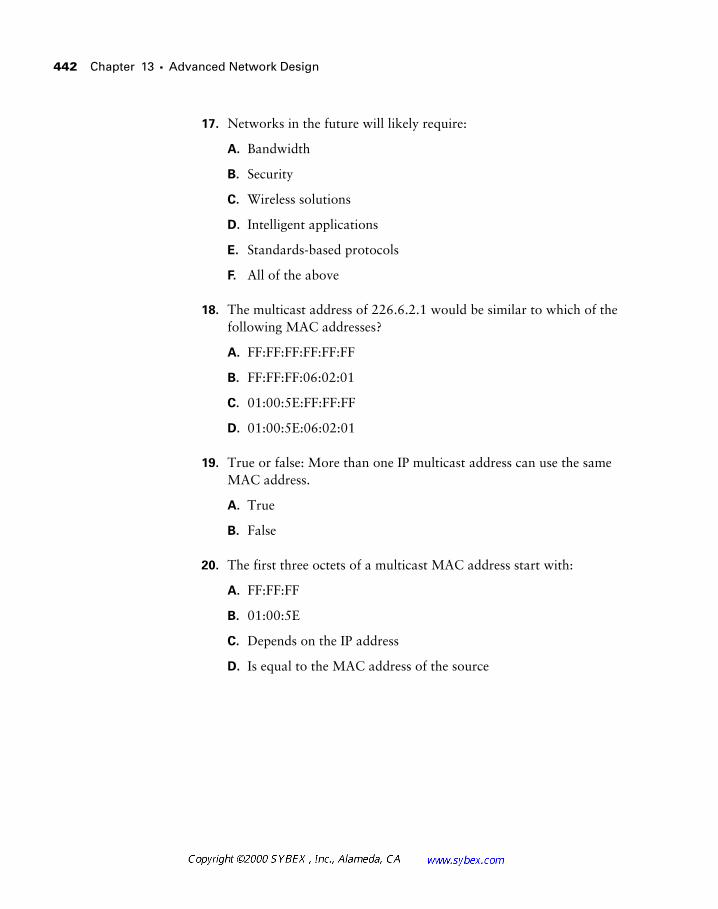
442 Chapter 13 � Advanced Network Design
17. Networks in the future will likely require:
A. Bandwidth
B. Security
C. Wireless solutions
D. Intelligent applications
E. Standards-based protocols
F. All of the above
18. The multicast address of 226.6.2.1 would be similar to which of the following MAC addresses?
A. FF:FF:FF:FF:FF:FF
B. FF:FF:FF:06:02:01
C. 01:00:5E:FF:FF:FF
D. 01:00:5E:06:02:01
19. True or false: More than one IP multicast address can use the same MAC address.
A. True
B. False
20. The first three octets of a multicast MAC address start with:
A. FF:FF:FF
B. 01:00:5E
C. Depends on the IP address
D. Is equal to the MAC address of the source

444
Chapter 13 �
Advanced Network Design
Answers to Review Questions
1.
D.
2.
C.
3.
B.
4.
B.
5.
C.
6.
A.
7.
B.
8.
A.
9.
C.
10.
A.
11.
A.
12.
B.
13.
C.
14.
B.
15.
A.
16.
B.
17.
F.
18.
D.
19.
A.
20.
B.

1. ESCON operates at:
A. 10Mbps
B. 17Mbps
C. 100Mbps
D. 17MBps
2. Without regard to the hierarchical model, queues are typically placed at which of the following points in the network?
A. Access-layer routers
B. Distribution-layer routers
C. At the transmitting interface of a router connected to a slow link
D. Only in the core
3. Which of the following is not an encapsulation method of serial tunneling?
A. Direct
B. HDLC
C. RSRB
D. TCP/IP
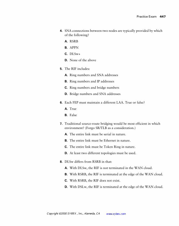
Practice Exam 447
4. SNA connections between two nodes are typically provided by which of the following?
A. RSRB
B. APPN
C. DLSw+
D. None of the above
5. The RIF includes:
A. Ring numbers and SNA addresses
B. Ring numbers and IP addresses
C. Ring numbers and bridge numbers
D. Bridge numbers and SNA addresses
6. Each FEP must maintain a different LAA. True or false?
A. True
B. False
7. Traditional source-route bridging would be most efficient in which environment? (Forgo SR/TLB as a consideration.)
A. The entire link must be serial in nature.
B. The entire link must be Ethernet in nature.
C. The entire link must be Token Ring in nature.
D. At least two different topologies must be used.
8. DLSw differs from RSRB in that:
A. With DLSw, the RIF is not terminated in the WAN cloud.
B. With RSRB, the RIF is terminated at the edge of the WAN cloud.
C. With RSRB, the RIF does not exist.
D. With DSLw, the RIF is terminated at the edge of the WAN cloud.

448 Appendix A � Practice Exam
9. By default, how often are hellos sent in EIGRP?
A. Every 3 seconds
B. Every 5 seconds
C. Every 10 seconds
D. Every 60 seconds
10. The best EIGRP designs are:
A. Hierarchical
B. Hub-and-spoke
C. Partial-mesh
D. Full-mesh
11. Following a link failure in EIGRP, without a feasible successor, the router will:
A. Flood the entire AS for a new route
B. Flood the entire network, including redistributed protocols, for a route
C. Wait for the next update window and listen for an announcement from the missing network
D. Query neighbor routers for a new route
12. Which best defines mobile hosts in EIGRP?
A. A wireless host
B. A host that is not located on its natural subnet
C. Workstations that use DHCP
D. None of the above. Only OSPF v2 supports mobile hosts.
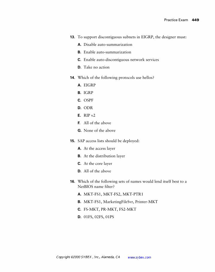
Practice Exam 449
13. To support discontiguous subnets in EIGRP, the designer must:
A. Disable auto-summarization
B. Enable auto-summarization
C. Enable auto-discontiguous network services
D. Take no action
14. Which of the following protocols use hellos?
A. EIGRP
B. IGRP
C. OSPF
D. ODR
E. RIP v2
F. All of the above
G. None of the above
15. SAP access lists should be deployed:
A. At the access layer
B. At the distribution layer
C. At the core layer
D. All of the above
16. Which of the following sets of names would lend itself best to a NetBIOS name filter?
A. MKT-FS1, MKT-FS2, MKT-PTR1
B. MKT-FS1, MarketingFileSvr, Printer-MKT
C. FS-MKT, PR-MKT, FS2-MKT
D. 01FS, 02FS, 01PS
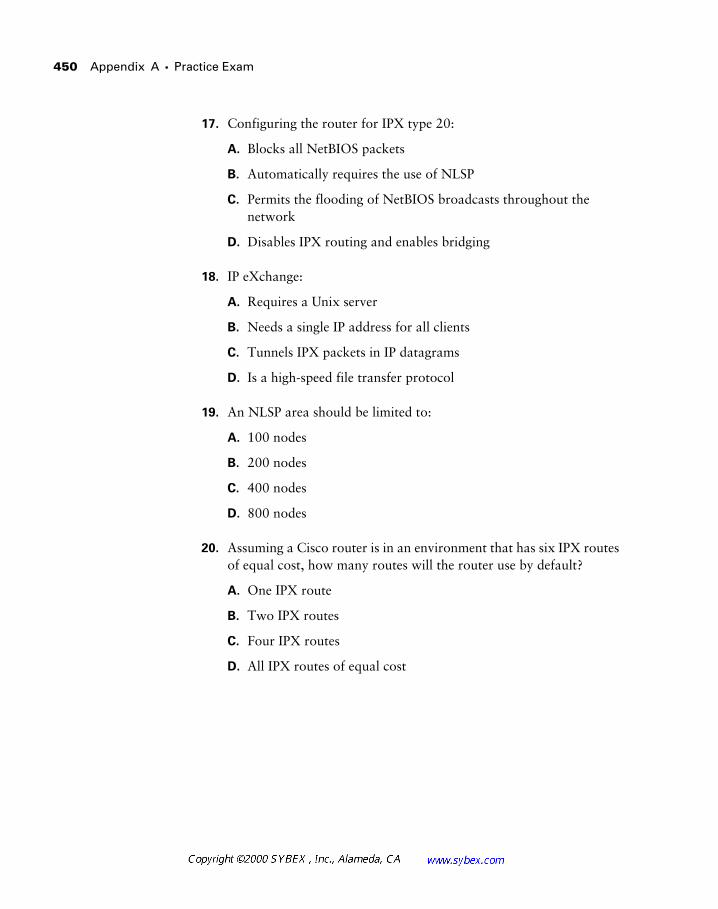
450 Appendix A � Practice Exam
17. Configuring the router for IPX type 20:
A. Blocks all NetBIOS packets
B. Automatically requires the use of NLSP
C. Permits the flooding of NetBIOS broadcasts throughout the network
D. Disables IPX routing and enables bridging
18. IP eXchange:
A. Requires a Unix server
B. Needs a single IP address for all clients
C. Tunnels IPX packets in IP datagrams
D. Is a high-speed file transfer protocol
19. An NLSP area should be limited to:
A. 100 nodes
B. 200 nodes
C. 400 nodes
D. 800 nodes
20. Assuming a Cisco router is in an environment that has six IPX routes of equal cost, how many routes will the router use by default?
A. One IPX route
B. Two IPX routes
C. Four IPX routes
D. All IPX routes of equal cost
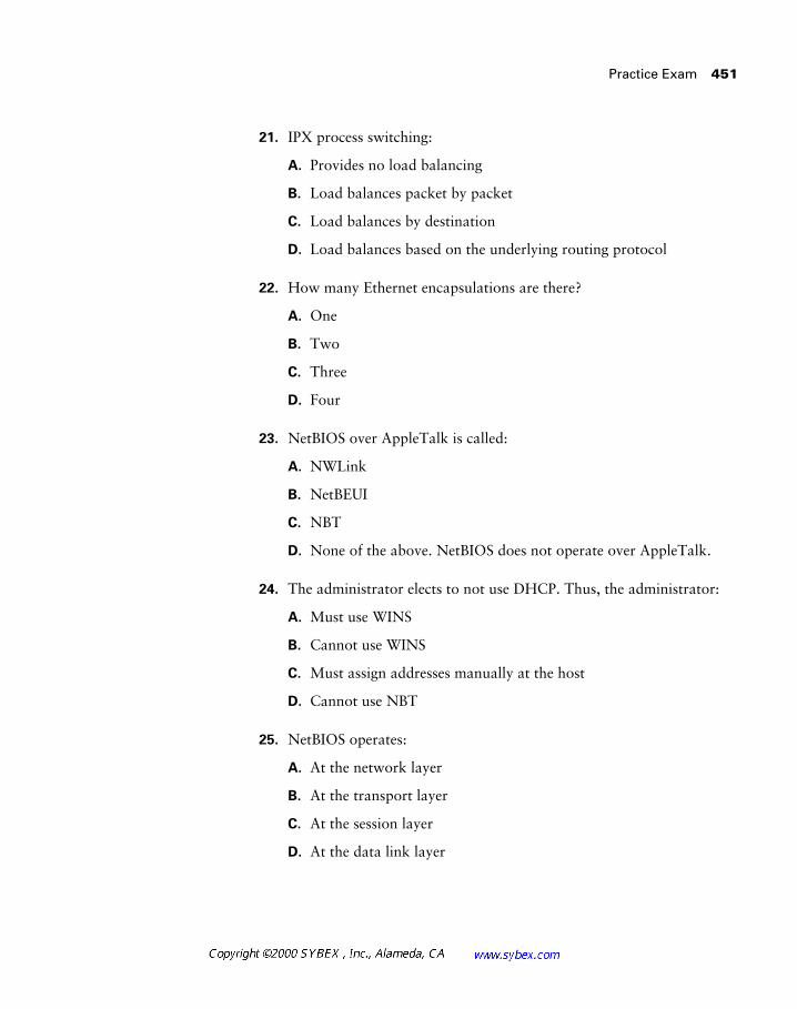
Practice Exam 451
21. IPX process switching:
A. Provides no load balancing
B. Load balances packet by packet
C. Load balances by destination
D. Load balances based on the underlying routing protocol
22. How many Ethernet encapsulations are there?
A. One
B. Two
C. Three
D. Four
23. NetBIOS over AppleTalk is called:
A. NWLink
B. NetBEUI
C. NBT
D. None of the above. NetBIOS does not operate over AppleTalk.
24. The administrator elects to not use DHCP. Thus, the administrator:
A. Must use WINS
B. Cannot use WINS
C. Must assign addresses manually at the host
D. Cannot use NBT
25. NetBIOS operates:
A. At the network layer
B. At the transport layer
C. At the session layer
D. At the data link layer
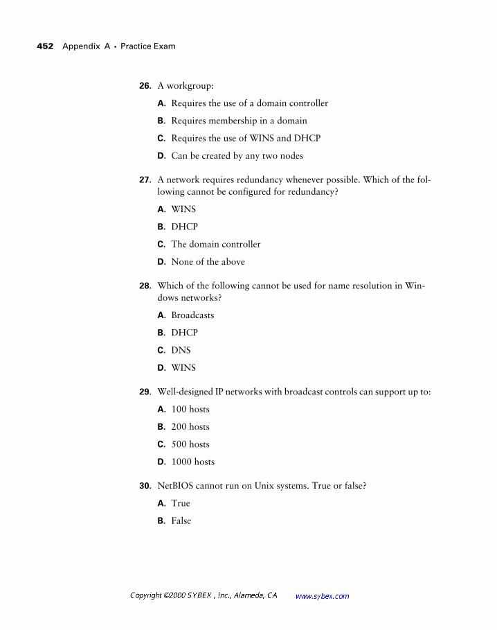
452 Appendix A � Practice Exam
26. A workgroup:
A. Requires the use of a domain controller
B. Requires membership in a domain
C. Requires the use of WINS and DHCP
D. Can be created by any two nodes
27. A network requires redundancy whenever possible. Which of the fol-lowing cannot be configured for redundancy?
A. WINS
B. DHCP
C. The domain controller
D. None of the above
28. Which of the following cannot be used for name resolution in Win-dows networks?
A. Broadcasts
B. DHCP
C. DNS
D. WINS
29. Well-designed IP networks with broadcast controls can support up to:
A. 100 hosts
B. 200 hosts
C. 500 hosts
D. 1000 hosts
30. NetBIOS cannot run on Unix systems. True or false?
A. True
B. False

Practice Exam 453
31. Which of the following is true regarding AAL 3/4?
A. It provides for 44 bytes of payload.
B. It includes a sequence number.
C. It includes a message identifier.
D. All of the above.
32. ATM headers provide which of the following?
A. VPI and DLCI
B. VCI and DLCI
C. DLCI and CIR
D. VPI and VCI
33. A network design must incorporate voice services. The designer should look to which technology as part of the solution?
A. Frame Relay
B. ATM
C. SMDS
D. Leased line
34. The default Frame Relay LMI encapsulation is which of the following?
A. Annex D
B. Annex A
C. Frame Relay Forum LMI
D. AAL 5 LMI
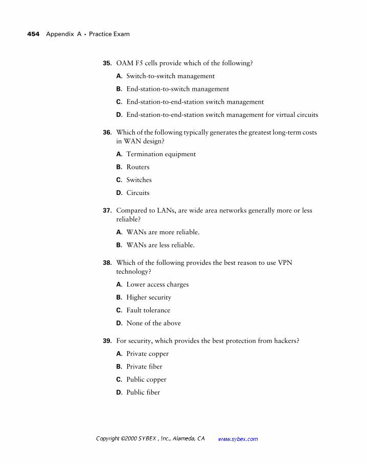
454 Appendix A � Practice Exam
35. OAM F5 cells provide which of the following?
A. Switch-to-switch management
B. End-station-to-switch management
C. End-station-to-end-station switch management
D. End-station-to-end-station switch management for virtual circuits
36. Which of the following typically generates the greatest long-term costs in WAN design?
A. Termination equipment
B. Routers
C. Switches
D. Circuits
37. Compared to LANs, are wide area networks generally more or less reliable?
A. WANs are more reliable.
B. WANs are less reliable.
38. Which of the following provides the best reason to use VPN technology?
A. Lower access charges
B. Higher security
C. Fault tolerance
D. None of the above
39. For security, which provides the best protection from hackers?
A. Private copper
B. Private fiber
C. Public copper
D. Public fiber
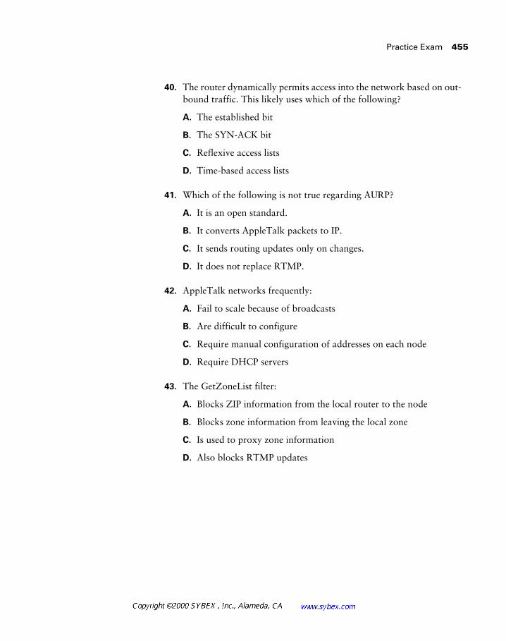
Practice Exam 455
40. The router dynamically permits access into the network based on out-bound traffic. This likely uses which of the following?
A. The established bit
B. The SYN-ACK bit
C. Reflexive access lists
D. Time-based access lists
41. Which of the following is not true regarding AURP?
A. It is an open standard.
B. It converts AppleTalk packets to IP.
C. It sends routing updates only on changes.
D. It does not replace RTMP.
42. AppleTalk networks frequently:
A. Fail to scale because of broadcasts
B. Are difficult to configure
C. Require manual configuration of addresses on each node
D. Require DHCP servers
43. The GetZoneList filter:
A. Blocks ZIP information from the local router to the node
B. Blocks zone information from leaving the local zone
C. Is used to proxy zone information
D. Also blocks RTMP updates
456 Appendix A � Practice Exam
44. What should the designer do when designing a tunnel for AppleTalk across IP? (Choose two.)
A. Use a star topology.
B. Remember that performance may degrade.
C. Note that only RTMP is permitted.
D. Use only AppleTalk phase one.
45. Which of the following would be the best zone name for a point-to-point WAN link between San Francisco and Chicago?
A. ZZZ-WAN-SFO-ORD
B. 3.4
C. WAN-SFO-ORD
D. Wan SFO ORD
46. Which of the following is not recommended in AppleTalk networks?
A. Use filtering where possible.
B. Do not use RTMP on WAN links.
C. Permit more than 500 nodes per segment.
D. Limit the number of resources per zone.
47. Vertical cable runs typically employ which of the following?
A. Copper wires
B. Fiber-optic cables
C. SONET
D. ATM
Practice Exam 457
48. Cisco switches (Catalyst 5000 series) can connect to which of the following via ISL?
A. Other Cisco switches
B. Other Cisco routers
C. ISL-aware NICs for servers
D. All of the above
49. A single router connects multiple switches in the building. This design is best described as:
A. A distributed backbone
B. A flat network
C. A collapsed backbone
D. A hybrid backbone
50. The designer installs a simple 10Mbps switch to replace a shared 10Mbps Ethernet hub. The theoretical increase in available band-width for 12 stations is:
A. The same
B. Doubled
C. Increased by a factor of 12
D. Not enough information provided

458 Appendix A � Practice Exam
Answers to Practice Exam
1. D.
2. C.
3. C.
4. B.
5. C.
6. B.
7. C.
8. D.
9. B.
10. A.
11. D.
12. B.
13. A.
14. A, C.
15. A.
16. A.
17. C.
18. B.
19. C.
20. A.
21. B.
22. D.
23. D.
24. C.

Answers to Practice Exam
459
25.
C.
26.
D.
27.
D.
28.
B.
29.
D.
30.
B.
31.
D.
32.
D.
33.
B.
34.
C.
35.
D.
36.
D.
37.
B.
38.
A.
39.
B.
40.
C.
41.
B.
42.
A.
43.
A.
44.
A, B.
45.
A.
46.
C.
47.
B.
48.
D.

460 Appendix A � Practice Exam
49. C.
50. C.
This is the best answer to the question; however, many designers would expand upon this by incorporating collisions, full versus half duplex, and number of nodes per segment. For example, half duplex yields a total of 10Mbps, while full duplex connections can double this. Also, many designers would consider the 10Mbps and divide this figure by 12 on a shared hub, yielding the bandwidth available per station.
1. True or false: SNA is a routable protocol.
A. True
B. False
2. In SRB, the routing information field is created by:
A. A proprietary protocol on Cisco routers
B. The end station only
C. The source station, by using explorer packets to discover each bridge in the network
D. Each Ethernet switch in the network
3. A router may learn of routes from which of the following? (Select two.)
A. Connected interfaces
B. BootP packets
C. Information learned from dynamic routing protocols
D. DHCP packets
Bonus Exam 463
4. Ideally, an OSPF design should incorporate which of the following?
A. A large area zero
B. Virtual links
C. Discontiguous subnets
D. All areas adjacent to area zero
5. True or false: An EIGRP router maintains the routing tables for all routers in the AS.
A. True
B. False
6. Which protocol uses feasible successors?
A. RIP
B. IGRP
C. OSPF
D. ODR
E. EIGRP
7. Which of the following is true regarding SAP updates?
A. They are sent every 30 seconds.
B. They are sent on updates only.
C. They are sent every 60 seconds.
D. They include 50 services per packet.
8. By default, IPX RIP packets are sent:
A. Every 10 seconds
B. Every 30 seconds
C. Every 60 seconds
D. On updates only
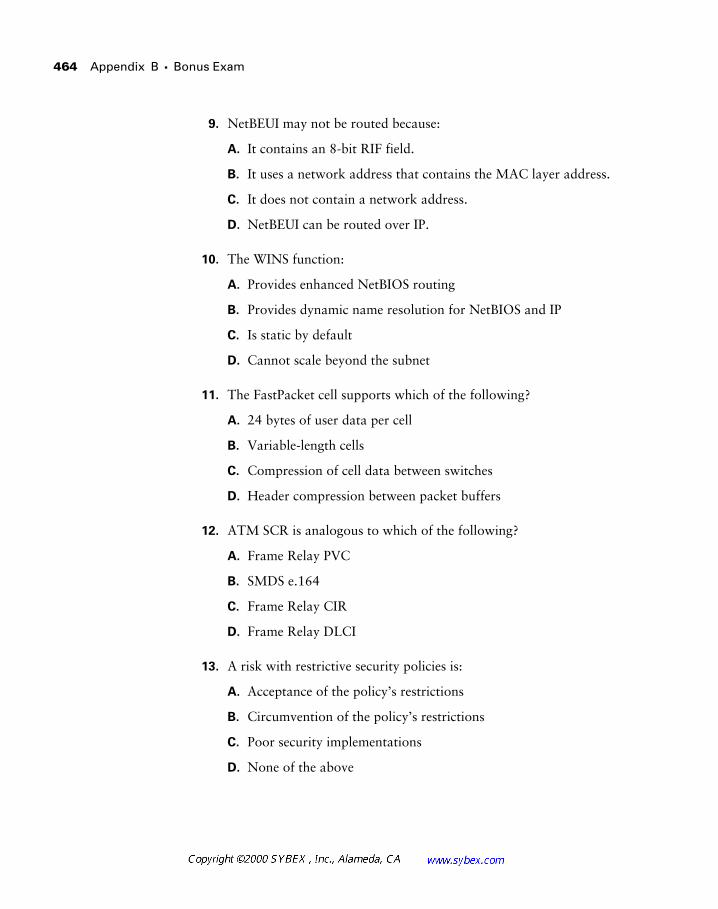
464 Appendix B � Bonus Exam
9. NetBEUI may not be routed because:
A. It contains an 8-bit RIF field.
B. It uses a network address that contains the MAC layer address.
C. It does not contain a network address.
D. NetBEUI can be routed over IP.
10. The WINS function:
A. Provides enhanced NetBIOS routing
B. Provides dynamic name resolution for NetBIOS and IP
C. Is static by default
D. Cannot scale beyond the subnet
11. The FastPacket cell supports which of the following?
A. 24 bytes of user data per cell
B. Variable-length cells
C. Compression of cell data between switches
D. Header compression between packet buffers
12. ATM SCR is analogous to which of the following?
A. Frame Relay PVC
B. SMDS e.164
C. Frame Relay CIR
D. Frame Relay DLCI
13. A risk with restrictive security policies is:
A. Acceptance of the policy’s restrictions
B. Circumvention of the policy’s restrictions
C. Poor security implementations
D. None of the above
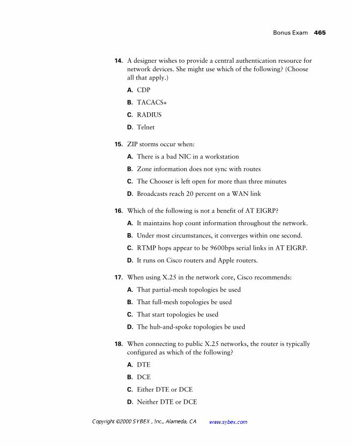
Bonus Exam 465
14. A designer wishes to provide a central authentication resource for network devices. She might use which of the following? (Choose all that apply.)
A. CDP
B. TACACS+
C. RADIUS
D. Telnet
15. ZIP storms occur when:
A. There is a bad NIC in a workstation
B. Zone information does not sync with routes
C. The Chooser is left open for more than three minutes
D. Broadcasts reach 20 percent on a WAN link
16. Which of the following is not a benefit of AT EIGRP?
A. It maintains hop count information throughout the network.
B. Under most circumstances, it converges within one second.
C. RTMP hops appear to be 9600bps serial links in AT EIGRP.
D. It runs on Cisco routers and Apple routers.
17. When using X.25 in the network core, Cisco recommends:
A. That partial-mesh topologies be used
B. That full-mesh topologies be used
C. That start topologies be used
D. The hub-and-spoke topologies be used
18. When connecting to public X.25 networks, the router is typically configured as which of the following?
A. DTE
B. DCE
C. Either DTE or DCE
D. Neither DTE or DCE

466 Appendix B � Bonus Exam
19. The use of subinterfaces in X.25 can avoid problems typically found in which types of WANs?
A. Non-multi-access
B. Broadcast multi-access
C. Unicast-broadcast
D. Non-broadcast multi-access
20. A router has received a packet destined for 172.17.90.2. Which route will most likely be used?
A. 10.0.0.0/8
B. 172.16.29.0/24
C. 0.0.0.0/0
D. 172.18.0.0/16
21. Which of the following may be used to support discontiguous subnets?
A. Secondaries
B. Tunnels
C. Classless routing protocols
D. All of the above
E. None of the above
22. Routers operate:
A. At Layer 2 and are slower than switches
B. At Layer 2 and are faster than switches
C. At Layer 3 and are faster than switches
D. At Layer 3 and are slower than switches
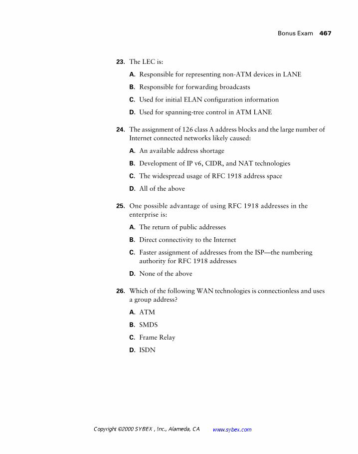
Bonus Exam 467
23. The LEC is:
A. Responsible for representing non-ATM devices in LANE
B. Responsible for forwarding broadcasts
C. Used for initial ELAN configuration information
D. Used for spanning-tree control in ATM LANE
24. The assignment of 126 class A address blocks and the large number of Internet connected networks likely caused:
A. An available address shortage
B. Development of IP v6, CIDR, and NAT technologies
C. The widespread usage of RFC 1918 address space
D. All of the above
25. One possible advantage of using RFC 1918 addresses in the enterprise is:
A. The return of public addresses
B. Direct connectivity to the Internet
C. Faster assignment of addresses from the ISP—the numbering authority for RFC 1918 addresses
D. None of the above
26. Which of the following WAN technologies is connectionless and uses a group address?
A. ATM
B. SMDS
C. Frame Relay
D. ISDN
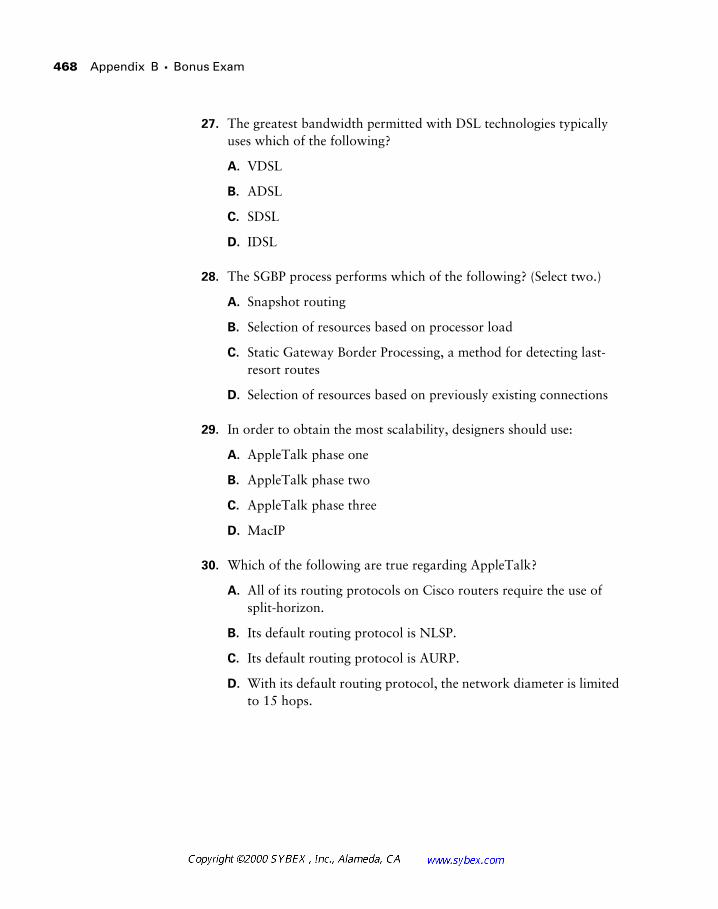
468 Appendix B � Bonus Exam
27. The greatest bandwidth permitted with DSL technologies typically uses which of the following?
A. VDSL
B. ADSL
C. SDSL
D. IDSL
28. The SGBP process performs which of the following? (Select two.)
A. Snapshot routing
B. Selection of resources based on processor load
C. Static Gateway Border Processing, a method for detecting last-resort routes
D. Selection of resources based on previously existing connections
29. In order to obtain the most scalability, designers should use:
A. AppleTalk phase one
B. AppleTalk phase two
C. AppleTalk phase three
D. MacIP
30. Which of the following are true regarding AppleTalk?
A. All of its routing protocols on Cisco routers require the use of split-horizon.
B. Its default routing protocol is NLSP.
C. Its default routing protocol is AURP.
D. With its default routing protocol, the network diameter is limited to 15 hops.
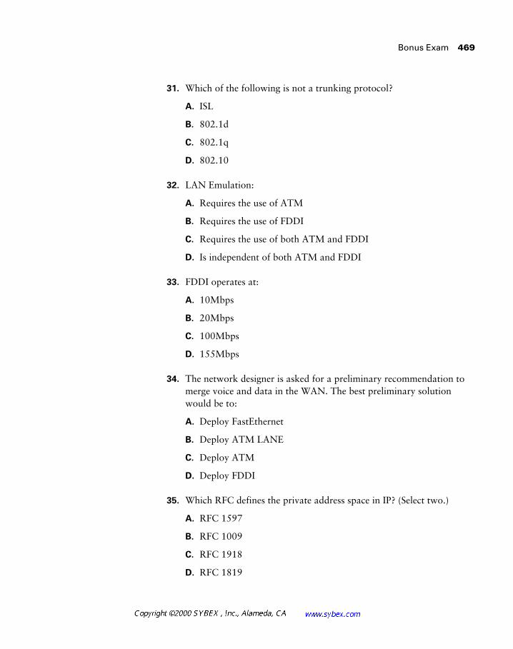
Bonus Exam 469
31. Which of the following is not a trunking protocol?
A. ISL
B. 802.1d
C. 802.1q
D. 802.10
32. LAN Emulation:
A. Requires the use of ATM
B. Requires the use of FDDI
C. Requires the use of both ATM and FDDI
D. Is independent of both ATM and FDDI
33. FDDI operates at:
A. 10Mbps
B. 20Mbps
C. 100Mbps
D. 155Mbps
34. The network designer is asked for a preliminary recommendation to merge voice and data in the WAN. The best preliminary solution would be to:
A. Deploy FastEthernet
B. Deploy ATM LANE
C. Deploy ATM
D. Deploy FDDI
35. Which RFC defines the private address space in IP? (Select two.)
A. RFC 1597
B. RFC 1009
C. RFC 1918
D. RFC 1819

470 Appendix B � Bonus Exam
36. The administrative distance for RIP, version 1, is:
A. 0
B. 1
C. 110
D. 115
E. 120
F. RIP, version 1, does not have an administrative distance.
37. Summarize 10.0.13.0 through 10.0.15.255.
A. 10.0.13.0/22
B. 10.0.13.0/24
C. 10.0.13.0/20
D. This address range cannot be summarized with a single entry.
38. Which answer best defines the primary purpose of a router?
A. Access control
B. Logical forwarding
C. Encryption
D. Media conversion
39. Network Address Translation is available: (Choose all that apply.)
A. With the PIX firewall
B. With any router running IOS 10.0 or higher
C. With any router running IOS 11.2 PLUS or higher
D. With any router running IOS 12.0 or higher
E. None of the above
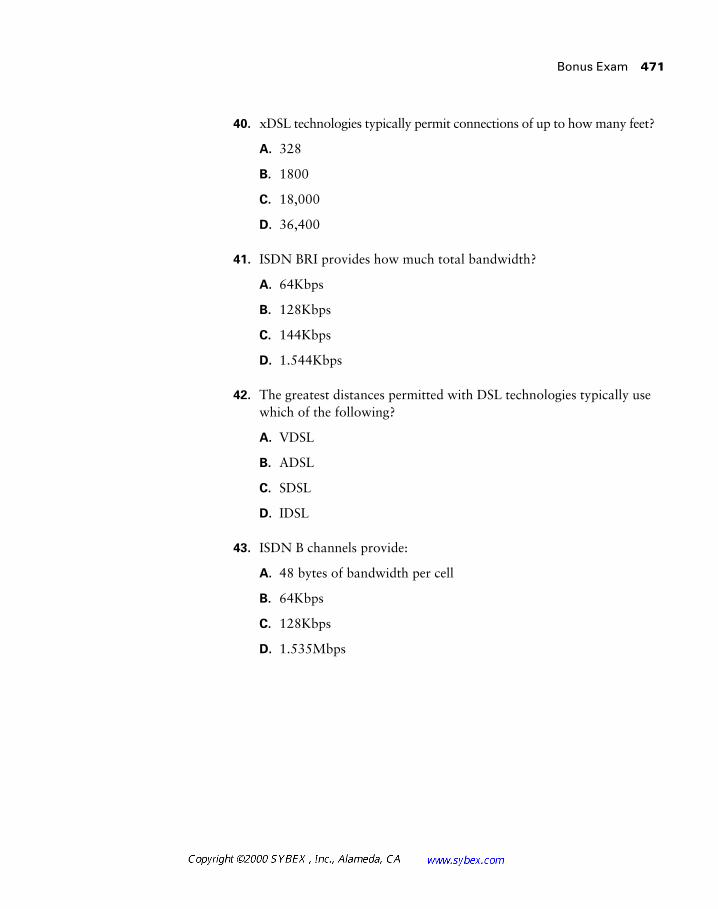
Bonus Exam 471
40. xDSL technologies typically permit connections of up to how many feet?
A. 328
B. 1800
C. 18,000
D. 36,400
41. ISDN BRI provides how much total bandwidth?
A. 64Kbps
B. 128Kbps
C. 144Kbps
D. 1.544Kbps
42. The greatest distances permitted with DSL technologies typically use which of the following?
A. VDSL
B. ADSL
C. SDSL
D. IDSL
43. ISDN B channels provide:
A. 48 bytes of bandwidth per cell
B. 64Kbps
C. 128Kbps
D. 1.535Mbps

472 Appendix B � Bonus Exam
44. X.25 uses which protocol at Layer 2?
A. LAPD
B. LAPB
C. HDLC
D. None of the above
45. In addition to split-horizon, what two items work to prevent routing loops?
A. Holddown timers
B. VLSM
C. Poison reverse
D. Route summarization
46. Link failure is detected with carrier loss or which of the following?
A. Redistribution
B. Keepalive timers
C. CDP packets
D. None of the above
47. True or false: OSPF is classful.
A. A. True
B. B. False
48. NAT, as opposed to NAT overload or PAT, supports which of the following?
A. A single IP address
B. A pool of IP addresses
C. A pool of IP networks
D. Any of the above

Bonus Exam 473
49. The designer has four DLCIs in the Frame Relay network terminating on the same router. How many physical interfaces are needed?
A. One
B. Two
C. Three
D. Four
50. LMI is carried on which DLCI?
A. Zero or 1023
B. Any
C. All
D. 31
51. Static ATM routes are defined with which of the following?
A. PNNI
B. EIGRP
C. IISP
D. UNI or NNI
52. Is that your final answer?
A. Yes, Regis, that is my final answer.
B. No, I want to ask the audience.
C. No, I want to phone a friend.
D. No, I want an IPO.

474 Appendix B � Bonus Exam
Answers to Bonus Exam
1. B.
2. C.
3. A, C.
4. D.
5. B.
6. E.
7. C.
8. C.
9. C.
10. B.
11. A.
12. C.
13. B.
14. B, C.
15. B.
16. D.
17. B.
18. B.
19. D.
20. C.
21. D.
22. D.
23. A.
24. D.

Answers to Bonus Exam
475
25.
A.
26.
B.
27.
A.
28.
B, D
29.
B.
30.
D.
31.
B.
32.
A.
33.
C.
34.
C.
35.
A, C.
36.
E.
37.
D.
38.
B.
39.
A, C, D.
40.
C.
41.
C.
42.
D.
43.
B.
44.
B.
45.
A, C.
46.
B.
47.
B.
48.
B.
49.
A.
50.
A.
It is impossible for anyone to keep track of all the developments in network design, especially when including the nuances introduced by differ-ent software versions and hardware platforms. Good network designers are usually better off not trying to learn everything. Rather, the best designers know how to locate and obtain the information they require. The ability to research is a powerful skill in the designer’s repertoire.
This appendix includes various references that should assist network designers. Note that not all of these sources were used in researching material for this book.
Web-Based Resources
This section lists some of the resources available on the Internet. By no means is it intended to be exhaustive.
While every effort has been made to provide an accurate list, the dynamic nature of the Internet and the static nature of this text will likely result in invalid references over time.
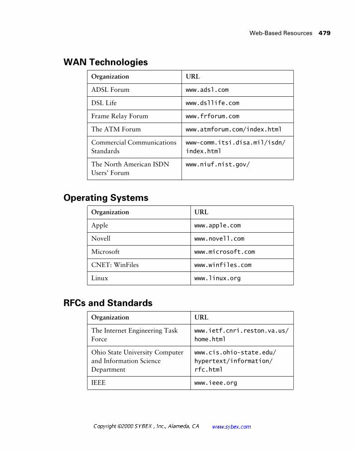
Web-Based Resources 479
WAN Technologies
Operating Systems
RFCs and Standards
Organization URL
ADSL Forum www.adsl.com
DSL Life www.dsllife.com
Frame Relay Forum www.frforum.com
The ATM Forum www.atmforum.com/index.html
Commercial Communications Standards
www-comm.itsi.disa.mil/isdn/index.html
The North American ISDN Users’ Forum
www.niuf.nist.gov/
Organization URL
Apple www.apple.com
Novell www.novell.com
Microsoft www.microsoft.com
CNET: WinFiles www.winfiles.com
Linux www.linux.org
Organization URL
The Internet Engineering Task Force
www.ietf.cnri.reston.va.us/home.html
Ohio State University Computer and Information Science Department
www.cis.ohio-state.edu/hypertext/information/rfc.html
IEEE www.ieee.org
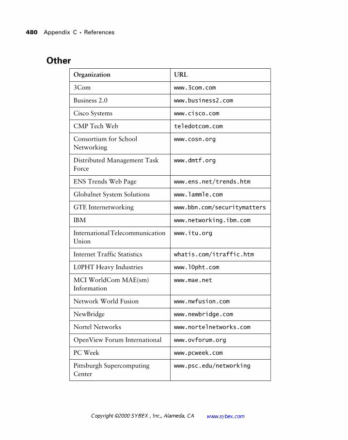
480 Appendix C � References
Other
Organization URL
3Com www.3com.com
Business 2.0 www.business2.com
Cisco Systems www.cisco.com
CMP Tech Web teledotcom.com
Consortium for School Networking
www.cosn.org
Distributed Management Task Force
www.dmtf.org
ENS Trends Web Page www.ens.net/trends.htm
Globalnet System Solutions www.lammle.com
GTE Internetworking www.bbn.com/securitymatters
IBM www.networking.ibm.com
International Telecommunication Union
www.itu.org
Internet Traffic Statistics whatis.com/itraffic.htm
L0PHT Heavy Industries www.l0pht.com
MCI WorldCom MAE(sm) Information
www.mae.net
Network World Fusion www.nwfusion.com
NewBridge www.newbridge.com
Nortel Networks www.nortelnetworks.com
OpenView Forum International www.ovforum.org
PC Week www.pcweek.com
Pittsburgh Supercomputing Center
www.psc.edu/networking
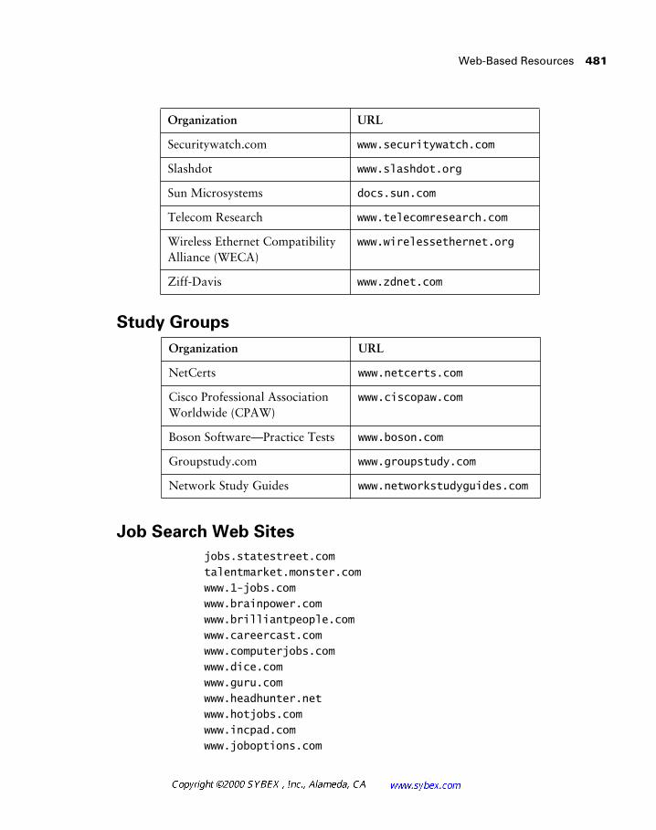
Web-Based Resources 481
Study Groups
Job Search Web Sites
jobs.statestreet.comtalentmarket.monster.comwww.1-jobs.comwww.brainpower.comwww.brilliantpeople.comwww.careercast.comwww.computerjobs.comwww.dice.comwww.guru.comwww.headhunter.netwww.hotjobs.comwww.incpad.comwww.joboptions.com
Organization URL
Securitywatch.com www.securitywatch.com
Slashdot www.slashdot.org
Sun Microsystems docs.sun.com
Telecom Research www.telecomresearch.com
Wireless Ethernet Compatibility Alliance (WECA)
www.wirelessethernet.org
Ziff-Davis www.zdnet.com
Organization URL
NetCerts www.netcerts.com
Cisco Professional Association Worldwide (CPAW)
www.ciscopaw.com
Boson Software—Practice Tests www.boson.com
Groupstudy.com www.groupstudy.com
Network Study Guides www.networkstudyguides.com
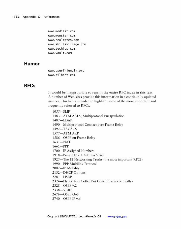
482 Appendix C � References
www.modisit.comwww.monster.comwww.realrates.comwww.skillsvillage.comwww.techies.comwww.vault.com
Humor
www.userfriendly.orgwww.dilbert.com
RFCs
It would be inappropriate to reprint the entire RFC index in this text. A number of Web sites provide this information in a continually updated manner. This list is intended to highlight some of the more important and frequently referred to RFCs.
1055—SLIP1483—ATM AAL5, Multiprotocol Encapsulation1487—LDAP1490—Multiprotocol Connect over Frame Relay1492—TACACS1577—ATM ARP1586—OSPF on Frame Relay1631—NAT1661—PPP1700—IP Assigned Numbers1918—Private IP v.4 Address Space1925—The 12 Networking Truths (the most important RFC?)1990—PPP Multilink Protocol2002—IP Mobility2132—DHCP Options2281—HSRP2324—Hyper Text Coffee Pot Control Protocol (really)2328—OSPF v.22338—VRRP2676—OSPF QoS2740—OSPF IP v.6
A&B bit signaling Used in T1 transmission facilities and sometimes called 24th channel signaling. Each of the 24 T1 subchannels in this procedure uses one bit of every sixth frame to send supervisory signaling information.
AAL ATM Adaptation Layer: A service-dependent sublayer of the data-link layer, which accepts data from other applications and brings it to the ATM layer in 48-byte ATM payload segments. CS and SAR are the two sub-layers that form AALs. Currently, the four types of AAL recommended by the ITU-T are AAL1, AAL2, AAL3/4, and AAL5. AALs are differentiated by the source-destination timing they use, whether they are CBR or VBR, and whether they are used for connection-oriented or connectionless mode data transmission. See also: AAL1, AAL2, AAL3/4, AAL5, CS, and SAR, ATM, and ATM layer.
AAL1 ATM Adaptation Layer 1: One of four AALs recommended by the ITU-T, it is used for connection-oriented, time-sensitive services that need constant bit rates, such as isochronous traffic and uncompressed video. See also: AAL.
AAL2 ATM Adaptation Layer 2: One of four AALs recommended by the ITU-T, it is used for connection-oriented services that support a variable bit rate, such as voice traffic. See also: AAL.
AAL3/4 ATM Adaptation Layer 3/4: One of four AALs (a product of two initially distinct layers) recommended by the ITU-T, supporting both con-nectionless and connection-oriented links. Its primary use is in sending SMDS packets over ATM networks. See also: AAL.
Glossary 485
AAL5 ATM Adaptation Layer 5: One of four AALs recommended by the ITU-T, it is used to support connection-oriented VBR services primarily to transfer classical IP over ATM and LANE traffic. This least complex of the AAL recommendations uses SEAL, offering lower bandwidth costs and simpler processing requirements but also providing reduced bandwidth and error-recovery capacities. See also: AAL.
AARP AppleTalk Address Resolution Protocol: The protocol in an Apple-Talk stack that maps data-link addresses to network addresses.
AARP probe packets Packets sent by the AARP to determine whether a given node ID is being used by another node in a nonextended AppleTalk network. If the node ID is not in use, the sending node appropriates that node’s ID. If the node ID is in use, the sending node will select a different ID and then send out more AARP probe packets. See also: AARP.
ABM Asynchronous Balanced Mode: When two stations can initiate a transmission, ABM is an HDLC (or one of its derived protocols) communi-cation technology that supports peer-oriented, point-to-point communications between both stations.
ABR Area Border Router: An OSPF router that is located on the border of one or more OSPF areas. ABRs are used to connect OSPF areas to the OSPF backbone area.
access list A set of test conditions kept by routers that determines “inter-esting traffic” to and from the router for various services on the network.
access method The manner in which network devices approach gaining access to the network itself.
access server Also known as a network access server, it is a communi-cations process connecting asynchronous devices to a LAN or WAN through network and terminal emulation software, providing synchronous or asynchronous routing of supported protocols.
acknowledgement Verification sent from one network device to another signifying that an event has occurred. May be abbreviated as ACK. Contrast with: NAK.
486 Glossary
ACR allowed cell rate: A designation defined by the ATM Forum for managing ATM traffic. Dynamically controlled using congestion control measures, the ACR varies between the minimum cell rate (MCR) and the peak cell rate (PCR). See also: MCR and PCR.
active monitor The mechanism used to manage a Token Ring. The net-work node with the highest MAC address on the ring becomes the active monitor and is responsible for management tasks such as preventing loops and ensuring tokens are not lost.
address mapping By translating network addresses from one format to another, this methodology permits different protocols to operate inter-changeably.
address mask A bit combination descriptor identifying which portion of an address refers to the network or subnet and which part refers to the host. Sometimes simply called the mask. See also: subnet mask.
address resolution The process used for resolving differences between computer addressing schemes. Address resolution typically defines a method for tracing network layer (Layer 3) addresses to data-link layer (Layer 2) addresses. See also: address mapping.
adjacency The relationship made between defined neighboring routers and end nodes, using a common media segment, to exchange routing information.
administrative distance A number between 0 and 225 that expresses the value of trustworthiness of a routing information source. The lower the number, the higher the integrity rating.
administrative weight A value designated by a network administrator to rate the preference given to a network link. It is one of four link metrics exchanged by PTSPs to test ATM network resource availability.
ADSU ATM Data Service Unit: The terminal adapter used to connect to an ATM network through an HSSI-compatible mechanism. See also: DSU.
advertising The process whereby routing or service updates are trans-mitted at given intervals, allowing other routers on the network to maintain a record of viable routes.
Glossary 487
AEP AppleTalk Echo Protocol: A test for connectivity between two Apple-Talk nodes where one node sends a packet to another and receives an echo, or copy, in response.
AFI Authority and Format Identifier: The part of an NSAP ATM address that delineates the type and format of the IDI section of an ATM address. See also: IDI and NSAP.
AFP AppleTalk Filing Protocol: A presentation-layer protocol, supporting AppleShare and Mac OS File Sharing, that permits users to share files and applications on a server.
AIP ATM Interface Processor: Supporting AAL3/4 and AAL5, this inter-face for Cisco 7000 series routers minimizes performance bottlenecks at the UNI. See also: AAL3/4 and AAL5.
algorithm A set of rules or process used to solve a problem. In networking, algorithms are typically used for finding the best route for traffic from a source to its destination.
alignment error An error occurring in Ethernet networks, in which a received frame has extra bits; that is, a number not divisible by eight. Align-ment errors are generally the result of frame damage caused by collisions.
all-routes explorer packet An explorer packet that can move across an entire SRB network, tracing all possible paths to a given destination. Also known as an all-rings explorer packet. See also: explorer packet, local explorer packet, and spanning explorer packet.
AM Amplitude Modulation: A modulation method that represents infor-mation by varying the amplitude of the carrier signal. See also: modulation.
AMI Alternate Mark Inversion: A line-code type on T1 and E1 circuits that shows zeros as “01” during each bit cell, and ones as “11” or “00,” alter-nately, during each bit cell. The sending device must maintain ones density in AMI but not independently of the data stream. Also known as binary-coded, alternate mark inversion. Contrast with: B8ZS. See also: ones density.
amplitude An analog or digital waveform’s highest value.
analog transmission Signal messaging whereby information is repre-sented by various combinations of signal amplitude, frequency, and phase.
488 Glossary
ANSI American National Standards Institute: The organization of corpo-rate, government, and other volunteer members that coordinates standards-related activities, approves U.S. national standards, and develops U.S. posi-tions in international standards organizations. ANSI assists in the creation of international and U.S. standards in disciplines such as communications, net-working, and a variety of technical fields. It publishes over 13,000 stan-dards, for engineered products and technologies ranging from screw threads to networking protocols. ANSI is a member of the IEC and ISO. See also: IEC and ISO.
anycast An ATM address that can be shared by more than one end system, allowing requests to be routed to a node that provides a particular service.
AppleTalk Currently in two versions, the group of communication proto-cols designed by Apple Computer for use in Macintosh environments. The earlier Phase 1 protocols support one physical network with only one net-work number that resides in one zone. The later Phase 2 protocols support more than one logical network on a single physical network, allowing net-works to exist in more than one zone. See also: zone.
application layer Layer 7 of the OSI reference network model, supplying services to application procedures (such as electronic mail or file transfer) that are outside the OSI model. This layer chooses and determines the avail-ability of communicating partners along with the resources necessary to make the connection, coordinates partnering applications, and forms a con-sensus on procedures for controlling data integrity and error recovery. See also: data-link layer, network layer, physical layer, presentation layer, session layer, and transport layer.
ARA AppleTalk Remote Access: A protocol for Macintosh users estab-lishing their access to resources and data from a remote AppleTalk location.
area A logical, rather than physical, set of segments (based on either CLNS, DECnet, or OSPF) along with their attached devices. Areas are com-monly connected to others using routers to create a single autonomous system. See also: autonomous system.
ARM Asynchronous Response Mode: An HDLC communication mode using one primary station and at least one additional station, in which trans-mission can be initiated from either the primary or one of the secondary units.
Glossary 489
ARP Address Resolution Protocol: Defined in RFC 826, the protocol that traces IP addresses to MAC addresses. See also: RARP.
ASBR Autonomous System Boundary Router: An area border router placed between an OSPF autonomous system and a non-OSPF network that operates both OSPF and an additional routing protocol, such as RIP. ASBRs must be located in a non-stub OSPF area. See also: ABR, non-stub area, and OSPF.
ASCII American Standard Code for Information Interchange: An eight-bit code for representing characters, consisting of seven data bits plus one parity bit.
ASN.1 Abstract Syntax Notation One: An OSI language used to describe types of data that is independent of computer structures and depicting methods. Described by ISO International Standard 8824.
ASP AppleTalk Session Protocol: A protocol employing ATP to establish, maintain, and tear down sessions, as well as sequence requests. See also: ATP.
AST Automatic Spanning Tree: A function that supplies one path for span-ning explorer frames traveling from one node in the network to another, sup-porting the automatic resolution of spanning trees in SRB networks. AST is based on the IEEE 802.1 standard. See also: IEEE 802.1 and SRB.
asynchronous transmission Digital signals sent without precise timing, usually with different frequencies and phase relationships. Asynchronous transmissions generally enclose individual characters in control bits (called start and stop bits) that show the beginning and end of each character. Contrast with: isochronous transmission and synchronous transmission.
ATCP AppleTalk Control Program: The protocol for establishing and con-figuring AppleTalk over PPP, defined in RFC 1378. See also: PPP.
ATDM Asynchronous Time-Division Multiplexing: A technique for sending information, it differs from normal TDM in that the time slots are assigned when necessary rather than preassigned to certain transmitters. Contrast with: FDM, statistical multiplexing, and TDM.
ATG Address Translation Gateway: The mechanism within Cisco DECnet routing software that enables routers to route multiple, independent DECnet networks and to establish a user-designated address translation for chosen nodes between networks.
490 Glossary
ATM Asynchronous Transfer Mode: The international standard, identified by fixed-length 53-byte cells, for transmitting cells in multiple service sys-tems, such as voice, video, or data. Transit delays are reduced because the fixed-length cells permit processing to occur in the hardware. ATM is designed to maximize the benefits of high-speed transmission media, such as SONET, E3, and T3.
ATM ARP server A device that supplies logical subnets running classical IP over ATM with address-resolution services.
ATM endpoint The initiating or terminating connection in an ATM net-work. ATM endpoints include servers, workstations, ATM-to-LAN switches, and ATM routers.
ATM Forum The international organization founded jointly by Northern Telecom, Sprint, Cisco Systems, and NET/ADAPTIVE in 1991 to develop and promote standards-based implementation agreements for ATM tech-nology. The ATM Forum broadens official standards developed by ANSI and ITU-T and creates implementation agreements before official standards are published.
ATM layer A sublayer of the data-link layer in an ATM network that is service independent. To create standard 53-byte ATM cells, the ATM layer receives 48-byte segments from the AAL and attaches a 5-byte header to each. These cells are then sent to the physical layer for transmission across the physical medium. See also: AAL.
ATMM ATM Management: A procedure that runs on ATM switches, managing rate enforcement and VCI translation. See also: ATM and VCI.
ATM user-user connection A connection made by the ATM layer to supply communication between at least two ATM service users, such as ATMM processes. These communications can be uni- or bidirectional, using one or two VCCs, respectively. See also: ATM layer and ATMM.
ATP AppleTalk Transaction Protocol: A transport-level protocol that enables reliable transactions between two sockets, where one requests the other to perform a given task and to report the results. ATP fastens the request and response together, assuring a loss-free exchange of request-response pairs.
Glossary 491
attenuation In communication, weakening or loss of signal energy, typi-cally caused by distance.
AURP AppleTalk Update-based Routing Protocol: A technique for encap-sulating AppleTalk traffic in the header of a foreign protocol that allows the connection of at least two noncontiguous AppleTalk internetworks through a foreign network (such as TCP/IP) to create an AppleTalk WAN. The con-nection made is called an AURP tunnel. By exchanging routing information between exterior routers, the AURP maintains routing tables for the com-plete AppleTalk WAN. See also: AURP tunnel and exterior router.
AURP tunnel A connection made in an AURP WAN that acts as a single, virtual link between AppleTalk internetworks separated physically by a for-eign network such as a TCP/IP network. See also: AURP.
authority zone A portion of the domain-name tree associated with DNS for which one name server is the authority. See also: DNS.
automatic call reconnect A function that enables automatic call rerouting away from a failed trunk line.
autonomous confederation A collection of self-governed systems that depend more on their own network accessibility and routing information than on information received from other systems or groups.
autonomous switching The ability of Cisco routers to process packets more quickly by using the ciscoBus to switch packets independently of the system processor.
autonomous system (AS) A group of networks under mutual adminis-tration that share the same routing methodology. Autonomous systems are subdivided by areas and must be assigned an individual 16-bit number by the IANA. See also: area and IANA.
autoreconfiguration A procedure executed by nodes within the failure domain of a Token Ring, wherein nodes automatically perform diagnostics, trying to reconfigure the network around failed areas.
B8ZS Binary 8-Zero Substitution: A line-code type, interpreted at the remote end of the connection, that uses a special code substitution whenever eight consecutive zeros are transmitted over the link on T1 and E1 circuits. This technique assures ones density independent of the data stream. Also known as bipolar 8-zero substitution. Contrast with: AMI. See also: ones density.
492 Glossary
backbone The basic portion of the network that provides the primary path for traffic sent to and initiated from other networks.
back end A node or software program supplying services to a front end. See also: client, front end, and server.
bandwidth The gap between the highest and lowest frequencies employed by network signals. More commonly, it refers to the rated throughput capacity of a network protocol or medium.
baseband A feature of a network technology that uses only one carrier fre-quency, for example Ethernet. Also named narrowband. Compare with: broadband.
baud Synonymous with bits per second (bps), if each signal element rep-resents one bit. It is a unit of signaling speed equivalent to the number of separate signal elements transmitted per second.
B channel Bearer channel: A full-duplex, 64Kbps channel in ISDN that transmits user data. Compare with: D channel, E channel, and H channel.
beacon An FDDI device or Token Ring frame that points to a serious problem with the ring, such as a broken cable. The beacon frame carries the address of the station thought to be down. See also: failure domain.
BECN Backward Explicit Congestion Notification: BECN is the bit set by a Frame Relay network in frames moving away from frames headed into a congested path. A DTE that receives frames with the BECN may ask higher-level protocols to take necessary flow-control measures. Compare with: FECN.
BGP4 BGP Version 4: Version 4 of the interdomain routing protocol most commonly used on the Internet. BGP4 supports CIDR and uses route-counting mechanisms to decrease the size of routing tables. See also: CIDR.
binary A two-character numbering method that uses ones and zeros. The binary numbering system underlies all digital representation of information.
BIP Bit Interleaved Parity: A method used in ATM to monitor errors on a link, sending a check bit or word in the link overhead for the previous block or frame. This allows bit errors in transmissions to be found and delivered as maintenance information.
Glossary
493
BISDN
Broadband ISDN: ITU-T standards created to manage high-bandwidth technologies such as video. BISDN presently employs ATM technology along SONET-based transmission circuits, supplying data rates between 155Mbps and 622Mbps and beyond. Contrast with N-ISDN.
See also: BRI, ISDN, and PRI.
bit-oriented protocol
Regardless of frame content, the class of data-link layer communication protocols that transmits frames. Bit-oriented proto-cols, as compared with byte-oriented, supply more efficient and trustworthy, full-duplex operation.
Compare with: byte-oriented protocol.
border gateway
A router that facilitates communication with routers in different autonomous systems.
BPDU
Bridge Protocol Data Unit: A Spanning-Tree Protocol initializing packet that is sent at definable intervals for the purpose of exchanging infor-mation among bridges in networks.
BRI
Basic Rate Interface: The ISDN interface that facilitates circuit-switched communication between video, data, and voice; it is made up of two B channels (64Kbps each) and one D channel (16Kbps).
Compare with: PRI. See also: BISDN, ISN.
bridge
A device for connecting two segments of a network and transmit-ting packets between them. Both segments must use identical protocols to communicate. Bridges function at the data-link layer, Layer 2 of the OSI ref-erence model. The purpose of a bridge is to filter, send, or flood any incoming frame, based on the MAC address of that particular frame.
broadband
A transmission methodology for multiplexing several inde-pendent signals onto one cable. In telecommunications, broadband is classi-fied as any channel with bandwidth greater than 4kHz (typical voice grade). In LAN terminology, it is classified as a coaxial cable on which analog signaling is employed. Also known as wideband.
Contrast with: baseband.
broadcast
A data frame or packet that is transmitted to every node on the local network segment (as defined by the broadcast domain). Broadcasts are known by their broadcast address, which is a destination network and host address with all the bits turned on. Also called local broadcast.
Compare with: directed broadcasts.
494 Glossary
broadcast domain A group of devices receiving broadcast frames initi-ating from any device within the group. Because they do not forward broad-cast frames, broadcast domains are generally surrounded by routers.
broadcast storm An undesired event on the network caused by the simul-taneous transmission of any number of broadcasts across the network seg-ment. Such an occurrence can overwhelm network bandwidth, resulting in time-outs.
buffer A storage area dedicated to handling data while in transit. Buffers are used to receive/store sporadic deliveries of data bursts, usually received from faster devices, compensating for the variations in processing speed. Incoming information is stored until everything is received prior to sending data on. Also known as an information buffer.
bus topology A linear LAN architecture in which transmissions from var-ious stations on the network are reproduced over the length of the medium and are accepted by all other stations. Compare with: ring, star, and tree topologies.
bus Any physical path, typically wires or copper, through which a digital signal can be used to send data from one part of a computer to another.
BUS broadcast and unknown server: In LAN emulation, the hardware or software responsible for resolving all broadcasts and packets with unknown (unregistered) addresses into the point-to-point virtual circuits required by ATM. See also: LEC, LECS, LES, and LANE.
BX.25 AT&T’s use of X.25. See also: X.25.
bypass mode An FDDI and Token Ring network operation that deletes an interface.
bypass relay A device that enables a particular interface in the Token Ring to be closed down and effectively taken off the ring.
byte-oriented protocol Any type of data-link communication protocol that, in order to mark the boundaries of frames, uses a specific character from the user character set. These protocols have generally been superseded by bit-oriented protocols. Compare with: bit-oriented protocol.
Glossary 495
cable range In an extended AppleTalk network, the range of numbers allotted for use by existing nodes on the network. The value of the cable range can be anywhere from a single to a sequence of several touching net-work numbers. Node addresses are determined by their cable range value.
CAC Connection Admission Control: The sequence of actions executed by every ATM switch while connection setup is performed in order to deter-mine if a request for connection is violating the guarantees of QoS for estab-lished connections. Also, CAC is used to route a connection request through an ATM network.
call admission control A device for managing of traffic in ATM net-works, determining the possibility of a path containing adequate bandwidth for a requested VCC.
call priority In circuit-switched systems, the defining priority given to each originating port; it specifies in which order calls will be reconnected. Addi-tionally, call priority identifies which calls are allowed during a bandwidth reservation.
call set-up time The length of time necessary to effect a switched call between DTE devices.
CBR Constant Bit Rate: An ATM Forum QoS class created for use in ATM networks. CBR is used for connections that rely on precision clocking to guarantee trustworthy delivery. Compare with: ABR and VBR.
CD Carrier Detect: A signal indicating that an interface is active or that a connection generated by a modem has been established.
CDP Cisco Discovery Protocol: Cisco’s proprietary protocol that is used to tell a neighbor Cisco device about the type of hardware, software version, and active interfaces that the Cisco device is using. It uses a SNAP frame between devices and is not routable.
CDVT Cell Delay Variation Tolerance: A QoS parameter for traffic man-agement in ATM networks specified when a connection is established. The allowable fluctuation levels for data samples taken by the PCR in CBR trans-missions are determined by the CDVT. See also: CBR and PCR.
496 Glossary
cell In ATM networking, the basic unit of data for switching and multi-plexing. Cells have a defined length of 53 bytes, including a 5-byte header that identifies the cell’s data stream and 48 bytes of payload. See also: cell relay.
cell payload scrambling The method by which an ATM switch maintains framing on some medium-speed edge and trunk interfaces (T3 or E3 cir-cuits). Cell payload scrambling rearranges the data portion of a cell to main-tain the line synchronization with certain common bit patterns.
cell relay A technology that uses small packets of fixed size, known as cells. Their fixed length enables cells to be processed and switched in hard-ware at high speeds, making this technology the foundation for ATM and other high-speed network protocols. See also: cell.
Centrex A local exchange carrier service, providing local switching that resembles that of an on-site PBX. Centrex has no on-site switching capa-bility. Therefore, all customer connections return to the CO. See also: CO.
CER Cell Error Ratio: The ratio in ATM of transmitted cells having errors to the total number of cells sent in a transmission within a certain span of time.
channelized E1 Operating at 2.048Mpbs, an access link that is sectioned into 29 B channels and one D channel, supporting DDR, Frame Relay, and X.25. Compare with: channelized T1.
channelized T1 Operating at 1.544Mbps, an access link that is sectioned into 23 B channels and one D channel of 64Kbps each, where individual channels or groups of channels connect to various destinations, supporting DDR, Frame Relay, and X.25. Compare with: channelized E1.
CHAP Challenge Handshake Authentication Protocol: Supported on lines using PPP encapsulation, it is a security feature that identifies the remote end, helping keep out unauthorized users. After CHAP is performed, the router or access server determines whether a given user is permitted access. It is a newer, more secure protocol than PAP. Compare with: PAP.
checksum A test for ensuring the integrity of sent data. It is a number cal-culated from a series of values taken through a sequence of mathematical func-tions, typically placed at the end of the data from which it is calculated, and then recalculated at the receiving end for verification. Compare with: CRC.
Glossary 497
choke packet When congestion exists, it is a packet sent to inform a trans-mitter that it should decrease its sending rate.
CIDR Classless Interdomain Routing: A method supported by classless routing protocols, such as OSPF and BGP4, based on the concept of ignoring the IP class of address, permitting route aggregation and VLSM that enable routers to combine routes in order to minimize the routing information that needs to be conveyed by the primary routers. It allows a group of IP net-works to appear to other networks as a unified, larger entity. In CIDR, IP addresses and their subnet masks are written as four dotted octets, followed by a forward slash and the numbering of masking bits (a form of subnet notation shorthand). See also: BGP4.
CIP Channel Interface Processor: A channel attachment interface for use in Cisco 7000 series routers that connects a host mainframe to a control unit. This device eliminates the need for an FBP to attach channels.
CIR Committed Information Rate: Averaged over a minimum span of time and measured in bps, a Frame Relay network’s agreed-upon minimum rate of transferring information.
Cisco FRAD Cisco Frame Relay access device: A Cisco product that sup-ports Cisco IPS Frame Relay SNA services, connecting SDLC devices to Frame Relay without requiring an existing LAN. May be upgraded to a fully functioning multiprotocol router. Can activate conversion from SDLC to Ethernet and Token Ring, but does not support attached LANs. See also: FRAD.
CiscoFusion Cisco’s name for the internetworking architecture under which its Cisco IOS operates. It is designed to “fuse” together the capabilities of its disparate collection of acquired routers and switches.
Cisco IOS software Cisco Internet Operating System software. The kernel of the Cisco line of routers and switches that supplies shared func-tionality, scalability, and security for all products under its CiscoFusion architecture. See also: CiscoFusion.
CiscoView GUI-based management software for Cisco networking devices, enabling dynamic status, statistics, and comprehensive configura-tion information. Displays a physical view of the Cisco device chassis and provides device-monitoring functions and fundamental troubleshooting capabilities. May be integrated with a number of SNMP-based network management platforms.
498 Glossary
classical IP over ATM Defined in RFC 1577, the specification for running IP over ATM that maximizes ATM features. Also known as CIA.
CLP Cell Loss Priority: The area in the ATM cell header that determines the likelihood of a cell being dropped during network congestion. Cells with CLP = 0 are considered insured traffic and are not apt to be dropped. Cells with CLP = 1 are considered best-effort traffic that may be dropped during congested episodes, delivering more resources to handle insured traffic.
CLR Cell Loss Ratio: The ratio of discarded cells to successfully delivered cells in ATM. CLR can be designated a QoS parameter when establishing a connection.
CO Central Office: The local telephone company office where all loops in a certain area connect and where circuit switching of subscriber lines occurs.
collapsed backbone A nondistributed backbone where all network seg-ments are connected to each other through an internetworking device. A col-lapsed backbone can be a virtual network segment at work in a device such as a router, hub, or switch.
collision The effect of two nodes sending transmissions simultaneously in Ethernet. When they meet on the physical media, the frames from each node collide and are damaged. See also: collision domain.
collision domain The network area in Ethernet over which frames that have collided will spread. Collisions are propagated by hubs and repeaters, but not by LAN switches, routers, or bridges. See also: collision.
configuration register A 16-bit configurable value stored in hardware or software that determines how Cisco routers function during initialization. In hardware, the bit position is set using a jumper. In software, it is set by spec-ifying specific bit patterns used to set startup options, configured using a hexadecimal value with configuration commands.
congestion Traffic that exceeds the network’s ability to handle it.
congestion avoidance To minimize delays, the method an ATM network uses to control traffic entering the system. Lower-priority traffic is discarded at the edge of the network when indicators signal it cannot be delivered, thus using resources efficiently.
Glossary 499
congestion collapse The situation that results from the retransmission of packets in ATM networks where little or no traffic successfully arrives at destination points. It usually happens in networks made of switches with ineffective or inadequate buffering capabilities combined with poor packet discard or ABR congestion feedback mechanisms.
connectionless Data transfer that occurs without the creating of a virtual circuit. No overhead, best-effort delivery, not reliable. Contrast with: connection-oriented. See also: virtual circuit.
connection-oriented Data transfer method that sets up a virtual circuit before any data is transferred. Uses acknowledgments and flow control for reliable data transfer. Contrast with: connectionless. See also: virtual circuit.
control direct VCC One of three control connections defined by Phase I LAN Emulation; a bi-directional virtual control connection (VCC) estab-lished in ATM by an LEC to an LES. See also: control distribute VCC.
control distribute VCC One of three control connections defined by Phase 1 LAN Emulation; a unidirectional virtual control connection (VCC) set up in ATM from an LES to an LEC. Usually, the VCC is a point-to-multipoint connection. See also: control direct VCC.
convergence The process required for all routers in an internetwork to update their routing tables and create a consistent view of the network, using the best possible paths. No user data is passed during a convergence time.
cost Also known as path cost, an arbitrary value, based on hop count, bandwidth, or other calculation, that is typically assigned by a network administrator and used by the routing protocol to compare different routes through an internetwork. Routing protocols use cost values to select the best path to a certain destination: the lowest cost identifies the best path. See also: routing metric.
count to infinity A problem occurring in routing algorithms that are slow to converge where routers keep increasing the hop count to particular net-works. To avoid this problem, various solutions have been implemented into each of the different routing protocols. Some of those solutions include defining a maximum hop count (defining infinity), route poisoning, poison reverse, and split-horizon.
500 Glossary
CPCS Common Part Convergence Sublayer: One of two AAL sublayers that is service-dependent, it is further segmented into the CS and SAR sub-layers. The CPCS prepares data for transmission across the ATM network; it creates the 48-byte payload cells that are sent to the ATM layer. See also: AAL and ATM layer.
CPE Customer Premises Equipment: Items such as telephones, modems, and terminals installed at customer locations and connected to the telephone company network.
crankback In ATM, a correction technique used when a node somewhere on a chosen path cannot accept a connection setup request, blocking the request. The path is rolled back to an intermediate node, which then uses GCAC to attempt to find an alternate path to the final destination.
CRC Cyclical Redundancy Check: A methodology that detects errors, whereby the frame recipient makes a calculation by dividing frame contents with a prime binary divisor and compares the remainder to a value stored in the frame by the sending node. Contrast with: checksum.
CSMA/CD Carrier Sense Multiple Access Collision Detect: A technology defined by the Ethernet IEEE 802.3 committee. Each device senses the cable for a digital signal before transmitting. Also, CSMA/CD allows all devices on the network to share the same cable, but one at a time. If two devices transmit at the same time, a frame collision will occur and a jamming pattern will be sent; the devices will stop transmitting, wait a predetermined amount of time, and then try to transmit again.
CSU Channel Service Unit: A digital mechanism that connects end-user equipment to the local digital telephone loop. Frequently referred to along with the data service unit as CSU/DSU. See also: DSU.
CTD Cell Transfer Delay: For a given connection in ATM, the time period between a cell exit event at the source user-network interface (UNI) and the corresponding cell entry event at the destination. The CTD between these points is the sum of the total inter-ATM transmission delay and the total ATM processing delay.
cut-through frame switching A frame-switching technique that flows data through a switch so that the leading edge exits the switch at the output port before the packet finishes entering the input port. Frames will be read, pro-cessed, and forwarded by devices that use cut-through switching as soon as the destination address of the frame is confirmed and the outgoing port is identified.
Glossary 501
data direct VCC A bidirectional point-to-point virtual control connection (VCC) set up between two LECs in ATM and one of three data connections defined by Phase 1 LAN Emulation. Because data direct VCCs do not guar-antee QoS, they are generally reserved for UBR and ABR connections. Compare with: control distribute VCC and control direct VCC.
datagram A logical collection of information transmitted as a network layer unit over a medium without a previously established virtual circuit. IP datagrams have become the primary information unit of the Internet. At various layers of the OSI reference model, the terms cell, frame, message, packet, and segment also define these logical information groupings.
data-link control layer Layer 2 of the SNA architectural model, it is responsible for the transmission of data over a given physical link and com-pares somewhat to the data-link layer of the OSI model.
data-link layer Layer 2 of the OSI reference model, it ensures the trust-worthy transmission of data across a physical link and is primarily con-cerned with physical addressing, line discipline, network topology, error notification, ordered delivery of frames, and flow control. The IEEE has fur-ther segmented this layer into the MAC sublayer and the LLC sublayer. Also known as the link layer. Can be compared somewhat to the data-link control layer of the SNA model. See also: application layer, LLC, MAC, network layer, physical layer, presentation layer, session layer, and transport layer.
DCC Data Country Code: Developed by the ATM Forum, one of two ATM address formats designed for use by private networks. Compare with: ICD.
DCE data communications equipment (as defined by the EIA) or data circuit-terminating equipment (as defined by the ITU-T): The mechanisms and links of a communications network that make up the network portion of the user-to-network interface, such as modems. The DCE supplies the physical connection to the network, forwards traffic, and provides a clocking signal to synchronize data transmission between DTE and DCE devices. Compare with: DTE.
D channel 1. Data channel: A full-duplex, 16Kbps (BRI) or 64Kbps (PRI) ISDN channel. Compare with: B channel, E channel, and H channel. 2. In SNA, anything that provides a connection between the processor and main storage with any peripherals.
502 Glossary
DDP Datagram Delivery Protocol : Used in the AppleTalk suite of proto-cols as a connectionless protocol that is responsible for sending datagrams through an internetwork.
DDR dial-on-demand routing: A technique that allows a router to auto-matically initiate and end a circuit-switched session per the requirements of the sending station. By mimicking keepalives, the router fools the end station into treating the session as active. DDR permits routing over ISDN or tele-phone lines via a modem or external ISDN terminal adapter.
default route The static routing table entry used to direct frames whose next hop is not spelled out in the dynamic routing table.
delay The time elapsed between a sender’s initiation of a transaction and the first response they receive. Also, the time needed to move a packet from its source to its destination over a path. See also: latency.
demarc The demarcation point between the customer premises equipment (CPE) and the telco’s carrier equipment.
demodulation A series of steps that return a modulated signal to its orig-inal form. When receiving, a modem demodulates an analog signal to its original digital form (and, conversely, modulates the digital data it sends into an analog signal). See also: modulation.
demultiplexing The process of converting a single multiplex signal, com-prising more than one input stream, back into separate output streams. See also: multiplexing.
designated bridge In the process of forwarding a frame from a segment to the route bridge, the bridge with the lowest path cost.
designated router An OSPF router that creates LSAs for a multiaccess network and is required to perform other special tasks in OSPF operations. Multiaccess OSPF networks that maintain a minimum of two attached routers identify one router that is chosen by the OSPF Hello protocol, which makes possible a decrease in the number of adjacencies necessary on a multi-access network. This in turn reduces the quantity of routing protocol traffic and the physical size of the database.
Glossary 503
destination address The address for the network devices that will receive a packet.
directed broadcast A data frame or packet that is transmitted to a specific group of nodes on a remote network segment. Directed broadcasts are known by their broadcast address, which is a destination subnet address with all the bits turned on. Compare with: local broadcasts.
discovery mode Also known as dynamic configuration, this technique is used by an AppleTalk interface to gain information from a working node about an attached network. The information is subsequently used by the interface for self-configuration.
distance-vector routing algorithm In order to find the shortest path, this group of routing algorithms repeats on the number of hops in a given route, requiring each router to send its complete routing table with each update, but only to its neighbors. Routing algorithms of this type tend to generate loops, but they are fundamentally simpler than their link-state counterparts. See also: link-state routing algorithm and SPF.
DLCI Data-Link Connection Identifier: Used to identify virtual circuits in a Frame Relay network.
DNS Domain Name System: Used to resolve host names to IP addresses.
DSAP Destination Service Access Point: The service access point of a network node, specified in the destination field of a packet. See also: SSAP and SAP.
DSR Data Set Ready: When a DCE is powered up and ready to run, this EIA/TIA-232 interface circuit is also engaged.
DSU Data Service Unit: This device is used to adapt the physical interface on a data terminal equipment (DTE) mechanism to a transmission facility such as T1 or E1 and is also responsible for signal timing. It is commonly grouped with the channel service unit and referred to as the CSU/DSU. See also: CSU.
DTE data terminal equipment: Any device located at the user end of a user-network interface serving as a destination, a source, or both. DTE includes devices such as multiplexers, protocol translators, and computers. The con-nection to a data network is made through data channel equipment (DCE) such as a modem, using the clocking signals generated by that device. See also: DCE.
504 Glossary
DTR data terminal ready: An activated EIA/TIA-232 circuit communi-cating to the DCE the state of preparedness of the DTE to transmit or receive data.
DUAL Diffusing Update Algorithm: Used in Enhanced IGRP, this conver-gence algorithm provides loop-free operation throughout an entire route’s computation. DUAL grants routers involved in a topology revision the ability to synchronize simultaneously, while routers unaffected by this change are not involved. See also: Enhanced IGRP.
DVMRP Distance Vector Multicast Routing Protocol: Based primarily on the Routing Information Protocol (RIP), this Internet gateway protocol implements a common, condensed-mode IP multicast scheme, using IGMP to transfer routing datagrams between its neighbors. See also: IGMP.
DXI Data Exchange Interface: Described in RFC 1482, DXI defines the effectiveness of a network device such as a router, bridge, or hub to act as an FEP to an ATM network by using a special DSU that accomplishes packet encapsulation.
dynamic routing Also known as adaptive routing, this technique auto-matically adapts to traffic or physical network revisions.
E1 Generally used in Europe, a wide-area digital transmission scheme carrying data at 2.048Mbps. E1 transmission lines are available for lease from common carriers for private use.
E.164 1. Evolved from standard telephone numbering system, the standard recommended by ITU-T for international telecommunication numbering, particularly in ISDN, SMDS, and BISDN. 2. Label of field in an ATM address containing numbers in E.164 format.
E channel Echo channel: A 64Kbps ISDN control channel used for cir-cuit switching. Specific description of this channel can be found in the 1984 ITU-T ISDN specification, but was dropped from the 1988 version. See also: B, D, and H channels.
edge device A device that enables packets to be forwarded between legacy interfaces (such as Ethernet and Token Ring) and ATM interfaces based on information in the data-link and network layers. An edge device does not take part in the running of any network layer routing protocol; it merely uses the route description protocol in order to get the forwarding information required.
Glossary 505
EEPROM Electronically Erasable Programmable Read-Only Memory: Programmed after their manufacture, these nonvolatile memory chips can be erased if necessary using electric power and reprogrammed. See also: EPROM, PROM.
EFCI Explicit Forward Congestion Indication: A congestion feedback mode permitted by ABR service in an ATM network. The EFCI may be set by any network element that is in a state of immediate or certain congestion. The des-tination end system is able to carry out a protocol that adjusts and lowers the cell rate of the connection based on value of the EFCI. See also: ABR.
EIGRP See: Enhanced IGRP.
EIP Ethernet Interface Processor: A Cisco 7000 series router interface pro-cessor card, supplying 10Mbps AUI ports to support Ethernet Version 1 and Ethernet Version 2 or IEEE 802.3 interfaces with a high-speed data path to other interface processors.
ELAN Emulated LAN: An ATM network configured using a client/server model in order to emulate either an Ethernet or Token Ring LAN. Multiple ELANs can exist at the same time on a single ATM network and are made up of an LAN Emulation Client (LEC), an LAN Emulation Server (LES), a broadcast and unknown server (BUS), and an LAN Emulation Configura-tion Server (LECS). ELANs are defined by the LANE specification. See also: LANE, LEC, LECS, and LES.
ELAP EtherTalk Link Access Protocol: In an EtherTalk network, the link-access protocol constructed above the standard Ethernet data-link layer.
encapsulation The technique used by layered protocols in which a layer adds header information to the protocol data unit (PDU) from the layer above. As an example, in Internet terminology, a packet would contain a header from the physical layer, followed by a header from the network layer (IP), followed by a header from the transport layer (TCP), followed by the application protocol data.
encryption The conversion of information into a scrambled form that effectively disguises it to prevent unauthorized access. Every encryption scheme uses some well-defined algorithm, which is reversed at the receiving end by an opposite algorithm in a process known as decryption.
506 Glossary
Enhanced IGRP Enhanced Interior Gateway Routing Protocol: An advanced routing protocol created by Cisco, combining the advantages of link-state and distance-vector protocols. Enhanced IGRP has superior con-vergence attributes, including high operating efficiency. See also: IGP, OSPF, and RIP.
enterprise network A privately owned and operated network that joins most major locations in a large company or organization.
EPROM Erasable Programmable Read-Only Memory: Programmed after their manufacture, these nonvolatile memory chips can be erased if necessary using high-power light and reprogrammed. See also: EEPROM, PROM.
ESF Extended Superframe: Made up of 24 frames with 192 bits each, with the 193rd bit providing other functions including timing. This is an enhanced version of SF. See also: SF.
Ethernet A baseband LAN specification created by the Xerox Corpora-tion and then improved through joint efforts of Xerox, Digital Equipment Corporation, and Intel. Ethernet is similar to the IEEE 802.3 series standard and, using CSMA/CD, operates over various types of cables at 10Mbps. Also called DIX (Digital/Intel/Xerox) Ethernet. See also: 10BaseT, Fast Ethernet, and IEEE.
EtherTalk A data-link product from Apple Computer that permits Apple-Talk networks to be connected by Ethernet.
excess rate In ATM networking, traffic exceeding a connection’s insured rate. The excess rate is the maximum rate less the insured rate. Depending on the availability of network resources, excess traffic can be discarded during congestion episodes. Compare with: maximum rate.
expansion The procedure of directing compressed data through an algo-rithm, restoring information to its original size.
expedited delivery An option that can be specified by one protocol layer, communicating either with other layers or with the identical protocol layer in a different network device, requiring that identified data be processed faster.
Glossary 507
explorer packet An SNA packet transmitted by a source Token Ring device to find the path through a source-route-bridged network.
failure domain The region in which a failure has occurred in a Token Ring. When a station gains information that a serious problem, such as a cable break, has occurred with the network, it sends a beacon frame that includes the station reporting the failure, its NAUN, and everything between. This defines the failure domain. Beaconing then initiates the pro-cedure known as autoreconfiguration. See also: autoreconfiguration and beacon.
fallback In ATM networks, this mechanism is used for scouting a path if it isn’t possible to locate one using customary methods. The device relaxes requirements for certain characteristics, such as delay, in an attempt to find a path that meets a certain set of the most important requirements.
FastEthernet Any Ethernet specification with a speed of 100Mbps. FastEthernet is ten times faster than 10BaseT, while retaining qualities like MAC mechanisms, MTU, and frame format. These similarities make it pos-sible for existing 10BaseT applications and management tools to be used on FastEthernet networks. FastEthernet is based on an extension of IEEE 802.3 specification (IEEE 802.3u). Compare with: Ethernet. See also: 100BaseT, 100BaseTX, and IEEE.
fast switching A Cisco feature that uses a route cache to speed packet switching through a router. Contrast with: process switching.
FDM Frequency-Division Multiplexing: A technique that permits informa-tion from several channels to be assigned bandwidth on one wire based on frequency. See also: TDM, ATDM, and statistical multiplexing.
FDDI Fiber Distributed Data Interface: A LAN standard, defined by ANSI X3T9.5, that can run at speeds up to 200Mbps and uses token-passing media access on fiber-optic cable. For redundancy, FDDI can use a dual-ring architecture.
FECN Forward Explicit Congestion Notification: A bit set by a Frame Relay network that informs the DTE receptor that congestion was encoun-tered along the path from source to destination. A device receiving frames with the FECN bit set can ask higher-priority protocols to take flow-control action as needed. See also: BECN.
508 Glossary
FEIP FastEthernet Interface Processor: An interface processor employed on Cisco 7000 series routers, supporting up to two 100Mbps 100BaseT ports.
firewall A barrier purposefully erected between any connected public net-works and a private network, made up of a router or access server or several routers or access servers, that uses access lists and other methods to ensure the security of the private network.
flash memory Developed by Intel and licensed to other semiconductor manufacturers, it is nonvolatile storage that can be erased electronically and reprogrammed, physically located on an EEPROM chip. Flash memory per-mits software images to be stored, booted, and rewritten as needed. Cisco routers and switches use flash memory to hold the IOS by default. See also: EPROM, EEPROM.
flooding When traffic is received on an interface, it is then transmitted to every interface connected to that device with exception of the interface from which the traffic originated. This technique can be used for traffic transfer by bridges and switches throughout the network.
flow control A methodology used to ensure that receiving units are not overwhelmed with data from sending devices. Pacing, as it is called in IBM networks, means that when buffers at a receiving unit are full, a message is transmitted to the sending unit to temporarily halt transmissions until all the data in the receiving buffer has been processed and the buffer is again ready for action.
FRAD Frame Relay access device: Any device affording a connection between a LAN and a Frame Relay WAN. See also: Cisco FRAD, FRAS.
fragment Any portion of a larger packet that has been intentionally seg-mented into smaller pieces. A packet fragment does not necessarily indicate an error and can be intentional. See also: fragmentation.
fragmentation The process of intentionally segmenting a packet into smaller pieces when sending data over an intermediate network medium that cannot support the larger packet size.
frame A logical unit of information sent by the data-link layer over a trans-mission medium. The term often refers to the header and trailer, employed for synchronization and error control, that surround the data contained in the unit.
Glossary 509
Frame Relay A more efficient replacement of the X.25 protocol (an unrelated packet relay technology that guarantees data delivery). Frame Relay is an industry-standard, shared-access, best-effort, switched data-link layer encapsulation that services multiple virtual circuits and protocols between connected mechanisms.
Frame Relay bridging Defined in RFC 1490, this bridging method uses the identical spanning-tree algorithm as other bridging operations but permits packets to be encapsulated for transmission across a Frame Relay network.
FRAS Frame Relay access support: A feature of Cisco IOS software that enables SDLC, Ethernet, Token Ring, and Frame Relay-attached IBM devices to be linked with other IBM mechanisms on a Frame Relay network. See also: FRAD.
frequency The number of cycles of an alternating current signal per time unit, measured in Hertz (cycles per second).
FSIP Fast Serial Interface Processor: The Cisco 7000 routers’ default serial interface processor, it provides four or eight high-speed serial ports.
FTP File Transfer Protocol: The TCP/IP protocol used for transmitting files between network nodes, it supports a broad range of file types and is defined in RFC 959. See also: TFTP.
full duplex The capacity to transmit information between a sending station and a receiving unit at the same time. See also: half duplex.
full mesh A type of network topology where every node has either a phys-ical or a virtual circuit linking it to every other network node. A full mesh supplies a great deal of redundancy but is typically reserved for network backbones because of its expense. See also: partial mesh.
GNS Get Nearest Server: On an IPX network, a request packet sent by a customer for determining the location of the nearest active server of a given type. An IPX network client launches a GNS request to get either a direct answer from a connected server or a response from a router disclosing the location of the service on the internetwork to the GNS. GNS is part of IPX and SAP. See also: IPX and SAP.
510 Glossary
GRE Generic Routing Encapsulation: A tunneling protocol created by Cisco with the capacity for encapsulating a wide variety of protocol packet types inside IP tunnels, thereby generating a virtual point-to-point connec-tion to Cisco routers across an IP network at remote points. IP tunneling using GRE permits network expansion across a single-protocol backbone environment by linking multiprotocol subnetworks in a single-protocol backbone environment.
guard band The unused frequency area found between two communica-tions channels, furnishing the space necessary to avoid interference between the two.
half duplex The capacity to transfer data in only one direction at a time between a sending unit and receiving unit. See also: full duplex.
handshake Any series of transmissions exchanged between two or more devices on a network to ensure synchronized operations.
H channel High-speed channel: A full-duplex, ISDN primary rate channel operating at a speed of 384Kbps. See also: B, D, and E channels.
HDLC High-Level Data-Link Control: Using frame characters, including checksums, HDLC designates a method for data encapsulation on synchro-nous serial links and is the default encapsulation for Cisco routers. HDLC is a bit-oriented synchronous data-link layer protocol created by ISO and derived from SDLC. However, most HDLC vendor implementations (including Cisco’s) are proprietary. See also: SDLC.
helper address The unicast address specified, which instructs the Cisco router to change the client’s local broadcast request for a service into a directed unicast to the server.
hierarchical addressing Any addressing plan employing a logical chain of commands to determine location. IP addresses are made up of a hierarchy of network numbers, subnet numbers, and host numbers to direct packets to the appropriate destination.
HIP HSSI Interface Processor: An interface processor used on Cisco 7000 series routers, providing one HSSI port that supports connections to ATM, SMDS, Frame Relay, or private lines at speeds up to T3 or E3.
Glossary 511
holddown The state a route is placed in so that routers can neither adver-tise the route nor accept advertisements about it for a defined time period. Holddown is used to surface bad information about a route from all routers in the network. A route is generally placed in holddown when one of its links fails.
hop The movement of a packet between any two network nodes. See also: hop count.
hop count A routing metric that calculates the distance between a source and a destination. RIP employs hop count as its sole metric. See also: hop and RIP.
HSCI High-Speed Communication Interface: Developed by Cisco, a single-port interface that provides full-duplex synchronous serial communications capability at speeds up to 52Mbps.
HSRP Hot Standby Router Protocol: A protocol that provides high net-work availability and provides nearly instantaneous hardware failover without administrator intervention. It generates a Hot Standby router group, including a lead router that lends its services to any packet being transferred to the Hot Standby address. If the lead router fails, it will be replaced by any of the other routers—the standby routers—that monitor it.
HSSI High-Speed Serial Interface: A network standard physical connector for high-speed serial linking over a WAN at speeds of up to 52Mbps.
ICD International Code Designator: Adapted from the subnetwork model of addressing, this assigns the mapping of network layer addresses to ATM addresses. HSSI is one of two ATM formats for addressing created by the ATM Forum to be utilized with private networks. See also: DCC.
ICMP Internet Control Message Protocol: Documented in RFC 792, it is a network layer Internet protocol for the purpose of reporting errors and pro-viding information pertinent to IP packet procedures.
IEEE Institute of Electrical and Electronics Engineers: A professional orga-nization that, among other activities, defines standards in a number of fields within computing and electronics, including networking and communica-tions. IEEE standards are the predominant LAN standards used today throughout the industry. Many protocols are commonly known by the ref-erence number of the corresponding IEEE standard.
512 Glossary
IEEE 802.1 The IEEE committee specification that defines the bridging group. The specification for STP (Spanning-Tree Protocol) is IEEE 802.1d. The STP uses SPA (spanning-tree algorithm) to find and prevent network loops in bridged networks. The specification for VLAN trunking is IEEE 802.1q. Compare to: ISL.
IEEE 802.3 The IEEE committee specification that defines the Ethernet group, specifically the original 10Mbps standard. Ethernet is a LAN pro-tocol that specifies physical layer and MAC sublayer media access. IEEE 802.3 uses CSMA/CD to provide access for many devices on the same net-work. FastEthernet is defined as 802.3u, and Gigabit Ethernet is defined as 802.3q. See also: CSMA/CD.
IEEE 802.5 IEEE committee that defines Token Ring media access.
IGMP Internet Group Management Protocol: Employed by IP hosts, the protocol that reports their multicast group memberships to an adjacent multicast router.
IGP Interior Gateway Protocol: Any protocol used by the Internet to exchange routing data within an independent system. Examples include RIP, IGRP, and OSPF.
ILMI Integrated (or Interim) Local Management Interface. A specification created by the ATM Forum, designated for the incorporation of network-management capability into the ATM UNI. Integrated Local Management Interface cells provide for automatic configuration between ATM systems. In LAN emulation, ILMI can provide sufficient information for the ATM end station to find an LECS. In addition, ILMI provides the ATM NSAP (Network Service Access Point) prefix information to the end station.
in-band management In-band management is the management of a net-work device “through” the network. Examples include using Simple Network Management Protocol (SNMP) or Telnet directly via the local LAN. Compare with: out-of-band management.
insured burst In an ATM network, it is the largest, temporarily permitted data burst exceeding the insured rate on a PVC and not tagged by the traffic policing function for being dropped if network congestion occurs. This insured burst is designated in bytes or cells.
Glossary 513
interarea routing Routing between two or more logical areas. Contrast with: intra-area routing. See also: area.
interface processor Any of several processor modules used with Cisco 7000 series routers. See also: AIP, CIP, EIP, FEIP, HIP, MIP, and TRIP.
Internet The global “network of networks,” whose popularity has exploded in the last few years. Originally a tool for collaborative academic research, it has become a medium for exchanging and distributing informa-tion of all kinds. The Internet’s need to link disparate computer platforms and technologies has led to the development of uniform protocols and stan-dards that have also found widespread use within corporate LANs. See also: TCP/IP and MBONE.
internet Before the rise of the Internet, this lowercase form was shorthand for “internetwork” in the generic sense. Now rarely used. See also: internetwork.
Internet protocol Any protocol belonging to the TCP/IP protocol stack. See also: TCP/IP.
internetwork Any group of private networks interconnected by routers and other mechanisms, typically operating as a single entity.
internetworking Broadly, anything associated with the general task of linking networks to each other. The term encompasses technologies, proce-dures, and products. When you connect networks to a router, you are cre-ating an internetwork.
intra-area routing Routing that occurs within a logical area. Contrast with: interarea routing.
Inverse ARP Inverse Address Resolution Protocol: A technique by which dynamic mappings are constructed in a network, allowing a device such as a router to locate the logical network address and associate it with a perma-nent virtual circuit (PVC). Commonly used in Frame Relay to determine the far-end node’s TCP/IP address by sending the Inverse ARP request to the local DLCI.
IP Internet Protocol: Defined in RFC 791, it is a network layer protocol that is part of the TCP/IP stack and allows connectionless service. IP fur-nishes an array of features for addressing, type-of-service specification, frag-mentation and reassembly, and security.
514 Glossary
IP address Often called an Internet address, this is an address uniquely identifying any device (host) on the Internet (or any TCP/IP network). Each address consists of four octets (32 bits), represented as decimal numbers sep-arated by periods (a format known as “dotted-decimal”). Every address is made up of a network number, an optional subnetwork number, and a host number. The network and subnetwork numbers together are used for routing, while the host number addresses an individual host within the net-work or subnetwork. The network and subnetwork information is extracted from the IP address using the subnet mask. There are five classes of IP addresses (A–E), which allocate different numbers of bits to the network, subnetwork, and host portions of the address. See also: CIDR, IP, and subnet mask.
IPCP IP Control Program: The protocol used to establish and configure IP over PPP. See also: IP and PPP.
IP multicast A technique for routing that enables IP traffic to be repro-duced from one source to several endpoints or from multiple sources to many destinations. Instead of transmitting only one packet to each indi-vidual point of destination, one packet is sent to a multicast group specified by only one IP endpoint address for the group.
IPX Internetwork Packet Exchange: Network layer protocol (Layer 3) used in Novell NetWare networks for transferring information from servers to workstations. Similar to IP and XNS.
IPXCP IPX Control Program: The protocol used to establish and configure IPX over PPP. See also: IPX and PPP.
IPXWAN Protocol used for new WAN links to provide and negotiate line options on the link using IPX. After the link is up and the options have been agreed upon by the two end-to-end links, normal IPX transmission begins.
ISDN Integrated Services Digital Network: Offered as a service by tele-phone companies, a communication protocol that allows telephone net-works to carry data, voice, and other digital traffic. See also: BISDN, BRI, and PRI.
isochronous transmission Asynchronous data transfer over a synchro-nous data-link, requiring a constant bit rate for reliable transport. Compare with: asynchronous transmission and synchronous transmission.
Glossary
515
ITU-T
International Telecommunication Union Telecommunication Stan-dardization Sector: This is a group of engineers that develops worldwide standards for telecommunications technologies.
LAN
Local Area Network: Broadly, any network linking two or more com-puters and related devices within a limited geographical area (up to a few kilometers). LANs are typically high-speed, low-error networks within a company. Cabling and signaling at the physical and data-link layers of the OSI are dictated by LAN standards. Ethernet, FDDI, and Token Ring are among the most popular LAN technologies.
Compare with: MAN and WAN.
LANE
LAN emulation: The technology that allows an ATM network to operate as a LAN backbone. To do so, the ATM network is required to pro-vide multicast and broadcast support, address mapping (MAC-to-ATM), SVC management, in addition to an operable packet format. Additionally, LANE defines Ethernet and Token Ring ELANs.
See also: ELAN.
LAN switch
A high-speed, multiple-interface transparent bridging mecha-nism, transmitting packets between segments of data-links, usually referred to specifically as an Ethernet switch. LAN switches transfer traffic based on MAC addresses. Multilayer switches are a type of high-speed, special-purpose, hardware-based router.
See also: multilayer switch, cut-through packet switching, and store-and-forward packet switching.
LAPB
Link Accessed Procedure, Balanced: A bit-oriented data-link layer protocol that is part of the X.25 stack and has its origin in SDLC.
See also: SDLC and X.25.
LAPD
Link Access Procedure on the D channel. The ISDN data-link layer protocol used specifically for the D channel and defined by ITU-T Recom-mendations Q.920 and Q.921. LAPD evolved from LAPB and is created to comply with the signaling requirements of ISDN basic access.
latency
Broadly, the time it takes a data packet to get from one location to another. In specific networking contexts, it can mean either 1) the time elapsed (delay) between the execution of a request for access to a network by a device and the time the mechanism actually is permitted transmission, or 2) the time elapsed between when a mechanism receives a frame and the time that frame is forwarded out of the destination port.
516 Glossary
Layer-3 switch See also: multilayer switch.
LCP Link Control Protocol: The protocol designed to establish, configure, and test data-link connections for use by PPP. See also: PPP.
leaky bucket An analogy for the basic cell rate algorithm (GCRA) used in ATM networks for checking the conformance of cell flows from a user or network. The bucket’s “hole” is understood to be the prolonged rate at which cells can be accommodated, and the “depth” is the tolerance for cell bursts over a certain time period. See also: GCRA.
learning bridge A bridge that transparently builds a dynamic database of MAC addresses and the interfaces associated with each address. Transparent bridges help to reduce traffic congestion on the network.
LE ARP LAN Emulation Address Resolution Protocol: The protocol pro-viding the ATM address that corresponds to a MAC address.
LEC LAN Emulation Client: Software providing the emulation of the link layer interface that allows the operation and communication of all higher-level protocols and applications to continue. The LEC client runs in all ATM devices, which include hosts, servers, bridges, and routers. The LANE client is responsible for address resolution, data transfer, address caching, inter-facing to the emulated LAN, and driver support for higher-level services. See also: ELAN and LES.
LECS LAN Emulation Configuration Server: An important part of emulated LAN services, providing the configuration data that is furnished upon request from the LES. These services include address registration for Integrated Local Management Interface (ILMI) support, configuration sup-port for the LES addresses and their corresponding emulated LAN identi-fiers, and an interface to the emulated LAN. See also: LES and ELAN.
LES LAN Emulation Server: The central LANE component that provides the initial configuration data for each connecting LEC. The LES typically is located on either an ATM-integrated router or a switch. Responsibilities of the LES include configuration and support for the LEC, address registration for the LEC, database storage and response concerning ATM addresses, and interfacing to the emulated LAN See also: ELAN, LEC, and LECS.
Glossary 517
link-state routing algorithm A routing algorithm that allows each router to broadcast or multicast information regarding the cost of reaching all its neighbors to every node in the internetwork. Link-state algorithms provide a consistent view of the network and are therefore not vulnerable to routing loops. However, this is achieved at the cost of somewhat greater difficulty in computation and more widespread traffic (compared with distance-vector routing algorithms). See also: distance-vector routing algorithm.
LLAP LocalTalk Link Access Protocol: In a LocalTalk environment, the data-link-level protocol that manages node-to-node delivery of data. This pro-tocol provides node addressing and management of bus access, and it also con-trols data sending and receiving to assure packet length and integrity.
LLC Logical Link Control: Defined by the IEEE, the higher of two data-link layer sublayers. LLC is responsible for error detection (but not correc-tion), flow control, framing, and software-sublayer addressing. The predom-inant LLC protocol, IEEE 802.2, defines both connectionless and connection-oriented operations. See also: data-link layer and MAC.
LMI An enhancement to the original Frame Relay specification. Among the features it provides are a keepalive mechanism, a multicast mechanism, global addressing, and a status mechanism.
LNNI LAN Emulation Network-to-Network Interface: In the Phase 2 LANE specification, an interface that supports communication between the server components within one ELAN.
local explorer packet In a Token Ring SRB network, a packet generated by an end system to find a host linked to the local ring. If no local host can be found, the end system will produce one of two solutions: a spanning explorer packet or an all-routes explorer packet.
LocalTalk Utilizing CSMA/CD, in addition to supporting data transmis-sion at speeds of 230.4Kbps, LocalTalk is Apple Computer’s proprietary baseband protocol, operating at the data-link and physical layers of the OSI reference model.
LSA link-state advertisement: Contained inside of link-state packets (LSPs), these advertisements are usually multicast packets, containing infor-mation about neighbors and path costs, that are employed by link-state pro-tocols. Receiving routers use LSAs to maintain their link-state databases and, ultimately, routing tables.
518 Glossary
LUNI LAN Emulation User-to-Network Interface: Defining the interface between the LAN Emulation Client (LEC) and the LAN Emulation Server, LUNI is the ATM Forum’s standard for LAN Emulation on ATM networks. See also: LES and LECS.
MAC Media Access Control: The lower sublayer in the data-link layer, it is responsible for hardware addressing, media access, and error detection of frames. See also: data-link layer and LLC.
MAC address A data-link layer hardware address that every port or device needs in order to connect to a LAN segment. These addresses are used by various devices in the network for accurate location of logical addresses. MAC addresses are defined by the IEEE standard and their length is six char-acters, typically using the burned-in address (BIA) of the local LAN inter-face. Variously called hardware address, physical address, burned-in address, or MAC-layer address.
MacIP In AppleTalk, the network layer protocol encapsulating IP packets in Datagram Delivery Protocol (DDP) packets. MacIP also supplies substi-tute ARP services.
MAN Metropolitan-Area Network: Any network that encompasses a met-ropolitan area; that is, an area typically larger than a LAN but smaller than a WAN. See also: LAN and WAN.
Manchester encoding A method for digital coding in which a mid-bit-time transition is employed for clocking, and a 1 (one) is denoted by a high voltage level during the first half of the bit time. This scheme is used by Ethernet and IEEE 802.3.
maximum burst Specified in bytes or cells, the largest burst of informa-tion exceeding the insured rate that will be permitted on an ATM permanent virtual connection for a short time and will not be dropped even if it goes over the specified maximum rate. Compare with: insured burst. See also: maximum rate.
maximum rate The maximum permitted data throughput on a particular virtual circuit, equal to the total of insured and uninsured traffic from the traffic source. Should traffic congestion occur, uninsured information may be deleted from the path. Measured in bits or cells per second, the maximum rate represents the highest throughput of data the virtual circuit is ever able to deliver and cannot exceed the media rate. Compare with: excess rate. See also: maximum burst.
Glossary 519
MBS Maximum Burst Size: In an ATM signaling message, this metric, coded as a number of cells, is used to convey the burst tolerance.
MBONE multicast backbone: The multicast backbone of the Internet, it is a virtual multicast network made up of multicast LANs, including point-to-point tunnels interconnecting them.
MCDV Maximum Cell Delay Variation: The maximum two-point CDV objective across a link or node for the identified service category in an ATM network. The MCDV is one of four link metrics that are exchanged using PTSPs to verify the available resources of an ATM network. Only one MCDV value is assigned to each traffic class.
MCLR Maximum Cell Loss Ratio: The maximum ratio of cells in an ATM network that fail to transit a link or node compared with the total number of cells that arrive at the link or node. MCDV is one of four link metrics that are exchanged using PTSPs to verify the available resources of an ATM net-work. The MCLR applies to cells in VBR and CBR traffic classes whose CLP bit is set to zero. See also: CBR, CLP, and VBR.
MCR Minimum Cell Rate: A parameter determined by the ATM Forum for traffic management of the ATM networks. MCR is specifically defined for ABR transmissions and specifies the minimum value for the allowed cell rate (ACR). See also: ACR and PCR.
MCTD Maximum Cell Transfer Delay: In an ATM network, the total of the maximum cell delay variation and the fixed delay across the link or node. MCTD is one of four link metrics that are exchanged using PNNI topology state packets to verify the available resources of an ATM network. There is one MCTD value assigned to each traffic class. See also: MCDV.
MIB Management Information Base: Used with SNMP management soft-ware to gather information from remote devices. The management station can poll the remote device for information, or the MIB running on the remote station can be programmed to send information on a regular basis.
MIP Multichannel Interface Processor: The resident interface processor on Cisco 7000 series routers, providing up to two channelized T1 or E1 con-nections by serial cables connected to a CSU. The two controllers are capable of providing 24 T1 or 30 E1 channel groups, with each group being intro-duced to the system as a serial interface that can be configured individually.
520 Glossary
mips millions of instructions per second: A measure of processor speed.
MLP Multilink PPP: A technique used to split, recombine, and sequence datagrams across numerous logical data-links.
MMP Multichassis Multilink PPP: A protocol that supplies MLP support across multiple routers and access servers. MMP enables several routers and access servers to work as a single, large dial-up pool with one network address and ISDN access number. MMP successfully supports packet frag-menting and reassembly when the user connection is split between two phys-ical access devices.
modem modulator-demodulator: A device that converts digital signals to analog and vice-versa so that digital information can be transmitted over analog communication facilities, such as voice-grade telephone lines. This is achieved by converting digital signals at the source to analog for transmis-sion and reconverting the analog signals back into digital form at the desti-nation. See also: modulation and demodulation.
modem eliminator A mechanism that makes possible a connection between two DTE devices without modems by simulating the commands and physical signaling required.
modulation The process of modifying some characteristic of an electrical signal, such as amplitude (AM) or frequency (FM), in order to represent digital or analog information. See also: AM.
MOSPF Multicast OSPF: An extension of the OSPF unicast protocol that enables IP multicast routing within the domain. See also: OSPF.
MPOA Multiprotocol over ATM: An effort by the ATM Forum to stan-dardize how existing and future network-layer protocols such as IP, Ipv6, AppleTalk, and IPX run over an ATM network with directly attached hosts, routers, and multilayer LAN switches.
MTU maximum transmission unit: The largest packet size, measured in bytes, that an interface can handle.
multicast Broadly, any communication between a single sender and mul-tiple receivers. Unlike broadcast messages, which are sent to all addresses on a network, multicast messages are sent to a defined subset of the network addresses; this subset has a group multicast address, which is specified in the packet’s destination address field. See also: broadcast, directed broadcast.
Glossary 521
multicast address A single address that points to more than one device on the network by specifying a special non-existent MAC address specified in that particular multicast protocol. Identical to group address. See also: multicast.
multicast send VCC A two-directional point-to-point virtual control con-nection (VCC) arranged by an LEC to a BUS, it is one of the three types of informational link specified by phase 1 LANE. See also: control distribute VCC and control direct VCC.
multilayer switch A highly specialized, high-speed, hardware-based type of LAN router, the device filters and forwards packets based on their Layer 2 MAC addresses and Layer 3 network addresses. It’s possible that even Layer 4 can be read. Sometimes called a Layer 3 switch. See also: LAN switch.
multiplexing The process of converting several logical signals into a single physical signal for transmission across one physical channel. Contrast with: demultiplexing.
NAK negative acknowledgment: A response sent from a receiver, telling the sender that the information was not received or contained errors. Compare with: acknowledgment.
NAT Network Address Translation: An algorithm instrumental in mini-mizing the requirement for globally unique IP addresses, permitting an orga-nization whose addresses are not all globally unique to connect to the Internet, regardless, by translating those addresses into globally routable address space.
NBP Name Binding Protocol: In AppleTalk, the transport-level protocol that interprets a socket client’s name, entered as a character string, into the corresponding DDP address. NBP gives AppleTalk protocols the capacity to discern user-defined zones and names of mechanisms by showing and keeping translation tables that map names to their corresponding socket addresses.
neighboring routers Two routers in OSPF that have interfaces to a common network. On networks with multiaccess, these neighboring routers are dynamically discovered using the Hello protocol of OSPF.
522 Glossary
NetBEUI NetBIOS Extended User Interface: An improved version of the NetBIOS protocol used in a number of network operating systems including LAN Manager, Windows NT, LAN Server, and Windows for Workgroups, implementing the OSI LLC2 protocol. NetBEUI formalizes the transport frame not standardized in NetBIOS and adds more functions. See also: OSI.
NetBIOS Network Basic Input/Output System: The API employed by applications residing on an IBM LAN to ask for services, such as session ter-mination or information transfer, from lower-level network processes.
NetView A mainframe network product from IBM, used for monitoring SNA (Systems Network Architecture) networks. It runs as a VTAM (Virtual Telecommunications Access Method) application.
NetWare A widely used NOS created by Novell, providing a number of distributed network services and remote file access.
network layer In the OSI reference model, it is Layer 3—the layer in which routing is implemented, enabling connections and path selection between two end systems. See also: application layer, data-link layer, phys-ical layer, presentation layer, session layer, and transport layer.
NFS Network File System: One of the protocols in Sun Microsystems’ widely used file system protocol suite, allowing remote file access across a network. The name is loosely used to refer to the entire Sun protocol suite, which also includes RPC, XDR (External Data Representation), and other protocols.
NHRP Next Hop Resolution Protocol: In a nonbroadcast multiaccess (NBMA) network, the protocol employed by routers in order to dynamically locate MAC addresses of various hosts and routers. It enables systems to communicate directly without requiring an intermediate hop, thus facili-tating increased performance in ATM, Frame Relay, X.25, and SMDS systems.
NHS Next Hop Server: Defined by the NHRP protocol, this server main-tains the next-hop resolution cache tables, listing IP-to-ATM address maps of related nodes and nodes that can be reached through routers served by the NHS.
Glossary 523
NIC network interface card: An electronic circuit board placed in a com-puter. The NIC provides network communication to a LAN.
NLSP NetWare Link Services Protocol: Novell’s link-state routing pro-tocol, based on the IS-IS model.
NMP Network Management Processor: A Catalyst 5000 switch processor module used to control and monitor the switch.
non-stub area In OSPF, a resource-consuming area carrying a default route, intra-area routes, interarea routes, static routes, and external routes. Non-stub areas are the only areas that can have virtual links configured across them and exclusively contain an anonymous system boundary router (ASBR). Compare with: stub area. See also: ASBR and OSPF.
NRZ Nonreturn to Zero: One of several encoding schemes for transmitting digital data. NRZ signals sustain constant levels of voltage with no signal shifting (no return to zero-voltage level) during a bit interval. If there is a series of bits with the same value (1 or 0), there will be no state change. The signal is not self-clocking. See also: NRZI.
NRZI Nonreturn to Zero Inverted: One of several encoding schemes for transmitting digital data. A transition in voltage level (either from high to low or vice-versa) at the beginning of a bit interval is interpreted as a value of 1; the absence of a transition is interpreted as a 0. Thus, the voltage assigned to each value is continually inverted. NRZI signals are not self-clocking. See also: NRZ.
NVRAM Non-Volatile RAM: Random-access memory that keeps its con-tents intact while power is turned off.
OC Optical Carrier: A series of physical protocols, designated as OC-1, OC-2, OC-3, and so on, for SONET optical signal transmissions. OC signal levels place STS frames on a multimode fiber-optic line at various speeds, of which 51.84Mbps is the lowest (OC-1). Each subsequent protocol runs at a speed divisible by 51.84. See also: SONET.
100BaseT Based on the IEEE 802.3u standard, 100BaseT is the Fast-Ethernet specification of 100Mbps baseband that uses UTP wiring. 100BaseT sends link pulses (containing more information than those used in 10BaseT) over the network when no traffic is present. See also: 10BaseT, FastEthernet, and IEEE 802.3.
524 Glossary
100BaseTX Based on the IEEE 802.3u standard, 100BaseTX is the 100Mbps baseband FastEthernet specification that uses two pairs of UTP or STP wiring. The first pair of wires receives data; the second pair sends data. To ensure correct signal timing, a 100BaseTX segment cannot be longer than 100 meters.
ones density Also known as pulse density, this is a method of signal clocking. The CSU/DSU retrieves the clocking information from data that passes through it. For this scheme to work, the data needs to be encoded to contain at least one binary 1 for each eight bits transmitted. See also CSU and DSU.
OSI Open System Interconnection: International standardization program designed by ISO and ITU-T for the development of data networking stan-dards that make multivendor equipment interoperability a reality.
OSI reference model Open System Interconnection reference model: A conceptual model defined by the International Organization for Standard-ization (ISO), describing how any combination of devices can be connected for the purpose of communication. The OSI model divides the task into seven functional layers, forming a hierarchy with the applications at the top and the physical medium at the bottom, and it defines the functions each layer must provide. See also: application layer, data-link layer, network layer, physical layer, presentation layer, session layer, and transport layer.
OSPF Open Shortest Path First: A link-state, hierarchical IGP routing algo-rithm derived from an earlier version of the IS-IS protocol, whose features include multipath routing, load balancing, and least-cost routing. OSPF is the suggested successor to RIP in the Internet environment. See also: enhanced IGRP, IGP, and IP.
out-of-band management Management “outside” of the network’s physical channels. For example, using a console connection not directly interfaced through the local LAN or WAN or a dial-in modem. Compare to: in-band management.
out-of-band signaling Within a network, any transmission that uses physical channels or frequencies separate from those ordinarily used for data transfer. For example, the initial configuration of a Cisco Catalyst switch requires an out-of-band connection via a console port.
Glossary 525
packet In data communications, the basic logical unit of information transferred. A packet consists of a certain number of data bytes, wrapped or encapsulated in headers and/or trailers that contain information about where the packet came from, where it’s going, and so on. The various pro-tocols involved in sending a transmission add their own layers of header information, which the corresponding protocols in receiving devices then interpret.
packet switch A physical device that makes it possible for a communica-tion channel to share several connections, its functions include finding the most efficient transmission path for packets.
packet switching A networking technology based on the transmission of data in packets. Dividing a continuous stream of data into small units—packets—enables data from multiple devices on a network to share the same communication channel simultaneously but also requires the use of precise routing information. Contrast with: circuit switching.
PAP Password Authentication Protocol: In Point-to-Point Protocol (PPP) networks, a method of validating connection requests. The requesting (remote) device must send an authentication request, containing a password and ID, to the local router when attempting to connect. Unlike the more secure CHAP (Challenge Handshake Authentication Protocol), PAP sends the password unencrypted and does not attempt to verify whether the user is authorized to access the requested resource; it merely identifies the remote end. See also: CHAP.
parity checking A method of error-checking in data transmissions. An extra bit (the parity bit) is added to each character or data word so that the sum of the bits will be either an odd number (in odd parity) or an even number (even parity).
partial mesh A type of network topology in which some network nodes form a full mesh (where every node has either a physical or a virtual circuit linking it to every other network node), but others are attached to only one or two nodes in the network. A typical use of partial-mesh topology is in peripheral networks linked to a fully meshed backbone. See also: full mesh.
PCR Peak Cell Rate: As defined by the ATM Forum, the parameter speci-fying, in cells per second, the maximum rate at which a source may transmit.
526 Glossary
PDN Public Data Network: Generally for a fee, a PDN offers the public access to computer communication network operated by private concerns or government agencies. Small organizations can take advantage of PDNs, aiding them in creating WANs without investing in long-distance equipment and circuitry.
PGP Pretty Good Privacy: A popular public-key/private-key encryption application offering protected transfer of files and messages.
physical layer The lowest layer—Layer 1—in the OSI reference model, it is responsible for converting data packets from the data-link layer (Layer 2) into electrical signals. Physical-layer protocols and standards define, for example, the type of cable and connectors to be used, including their pin assignments and the encoding scheme for signaling 0 and 1 values. See also: application layer, data-link layer, network layer, presentation layer, session layer, and transport layer.
ping packet Internet groper: A Unix-based Internet diagnostic tool, con-sisting of a message sent to test the accessibility of a particular device on the IP network. The acronym (from which the “full name” was formed) reflects the underlying metaphor of submarine sonar. Just as the sonar operator sends out a signal and waits to hear it echo (“ping”) back from a submerged object, the network user can ping another node on the network and wait to see if it responds.
pleisochronous Nearly synchronous, except that clocking comes from an outside source instead of being embedded within the signal as in synchro-nous transmissions.
PLP Packet Level Protocol: Occasionally called X.25 Level 3 or X.25 Protocol, a network-layer protocol that is part of the X.25 stack.
PNNI Private Network-Network Interface: An ATM Forum specification for offering topology data used for the calculation of paths through the net-work, among switches and groups of switches. It is based on well-known link-state routing procedures and allows for automatic configuration in net-works whose addressing scheme is determined by the topology.
point-to-multipoint connection In ATM, a communication path going only one way, connecting a single system at the starting point, called the “root node,” to systems at multiple points of destination, called “leaves.” See also: point-to-point connection.
Glossary 527
point-to-point connection In ATM, a channel of communication that can be directed either one way or two ways between two ATM end systems. See also: point-to-multipoint connection.
poison reverse updates These update messages are transmitted by a router back to the originator (thus ignoring the split-horizon rule) after route poisoning has occurred. Typically used with DV routing protocols in order to overcome large routing loops and offer explicit information when a subnet or network is not accessible (instead of merely suggesting that the network is unreachable by not including it in updates). See also: route poisoning.
polling The procedure of orderly inquiry, used by a primary network mechanism, to determine if secondary devices have data to transmit. A mes-sage is sent to each secondary, granting the secondary the right to transmit.
POP 1. Point Of Presence: The physical location where an interexchange carrier has placed equipment to interconnect with a local exchange carrier. 2. Post Office Protocol (currently at version 3): A protocol used by client e-mail applications for recovery of mail from a mail server.
PPP Point-to-Point Protocol: The protocol most commonly used for dial-up Internet access, superseding the earlier SLIP. Its features include address notification, authentication via CHAP or PAP, support for multiple proto-cols, and link monitoring. PPP has two layers: the Link Control Protocol (LCP) establishes, configures, and tests a link; and then any of various Net-work Control Programs (NCPs) transport traffic for a specific protocol suite, such as IPX. See also: CHAP, PAP, and SLIP.
presentation layer Layer 6 of the OSI reference model, it defines how data is formatted, presented, encoded, and converted for use by software at the application layer. See also: application layer, data-link layer, network layer, physical layer, session layer, and transport layer.
PRI Primary Rate Interface: A type of ISDN connection between a PBX and a long-distance carrier, which is made up of a single 64Kbps D channel in addition to 23 (T1) or 30 (E1) B channels. See also: ISDN.
priority queueing A routing function in which frames temporarily placed in an interface output queue are assigned priorities based on traits such as packet size or type of interface.
528 Glossary
process switching As a packet arrives on a router to be forwarded, it’s copied to the router’s process buffer, and the router performs a lookup on the Layer 3 address. Using the route table, an exit interface is associated with the destination address. The processor forwards the packet with the added new information to the exit interface, while the router initializes the fast-switching cache. Subsequent packets bound for the same destination address follow the same path as the first packet.
PROM programmable read-only memory: ROM that is programmable only once, using special equipment. Compare with: EPROM.
propagation delay The time it takes data to traverse a network from its source to its destination.
protocol In networking, the specification of a set of rules for a particular type of communication. The term is also used to refer to the software that implements a protocol.
protocol stack A collection of related protocols.
PSE Packet Switch Exchange: The X.25 term for a switch.
PSN packet-switched network: Any network that uses packet-switching technology. Also known as packet-switched data network (PSDN). See also: packet switching.
PSTN Public Switched Telephone Network: Colloquially referred to as “plain old telephone service” (POTS). A term that describes the assortment of telephone networks and services available globally.
PVC permanent virtual circuit: In a Frame Relay network, a logical con-nection, defined in software, that is maintained permanently. Compare with: SVC. See also: virtual circuit.
PVP permanent virtual path: A virtual path made up of PVCs. See also: PVC.
PVP tunneling permanent virtual path tunneling: A technique that links two private ATM networks across a public network using a virtual path; wherein the public network transparently trunks the complete collection of virtual channels in the virtual path between the two private networks.
Glossary 529
QoS Quality of Service: A set of metrics used to measure the quality of transmission and service availability of any given transmission system.
queue Broadly, any list of elements arranged in an orderly fashion and ready for processing, such as a line of people waiting to enter a movie the-ater. In routing, it refers to a backlog of information packets waiting in line to be transmitted over a router interface.
RARP Reverse Address Resolution Protocol: The protocol within the TCP/IP stack that maps MAC addresses to IP addresses. See also: ARP.
rate queue A value, assigned to one or more virtual circuits, that specifies the speed at which an individual virtual circuit will transmit data to the remote end. Every rate queue identifies a segment of the total bandwidth available on an ATM link. The sum of all rate queues should not exceed the total available bandwidth.
RCP Remote Copy Protocol: A protocol for copying files to or from a file system that resides on a remote server on a network, using TCP to guarantee reliable data delivery.
redistribution Command used in Cisco routers to inject the paths found from one type of routing protocol into another type of routing protocol. For example, networks found by RIP can be inserted into an IGRP network.
redundancy In internetworking, the duplication of connections, devices, or services that can be used as a backup in the event that the primary con-nections, devices, or services fail.
reload An event or command that causes Cisco routers to reboot.
RIF Routing Information Field: In source-route bridging, a header field that defines the path direction of the frame or token. If the Route Informa-tion Indicator (RII) bit is not set, the RIF is read from source to destination (left to right). If the RII bit is set, the RIF is read from the destination back to the source, so the RIF is read right to left. It is defined as part of the Token Ring frame header for source-routed frames, which contains path information.
530 Glossary
ring Two or more stations connected in a logical circular topology. In this topology, which is the basis for Token Ring, FDDI, and CDDI, information is transferred from station to station in sequence.
ring topology A network logical topology comprising a series of repeaters that form one closed loop by connecting unidirectional transmission links. Individual stations on the network are connected to the network at a repeater. Physically, ring topologies are generally organized in a closed-loop star. Compare with: bus topology and star topology.
RIP Routing Information Protocol: The most commonly used interior gateway protocol in the Internet. RIP employs hop count as a routing metric. See also: Enhanced IGRP, IGP, OSPF, and hop count.
routed protocol Routed protocols (such as IP and IPX) are used to transmit user data through an internetwork. By contrast, routing protocols (such as RIP, IGRP, and OSPF) are used to update routing tables between routers.
route poisoning Used by various DV routing protocols in order to over-come large routing loops and offer explicit information about when a subnet or network is not accessible (instead of merely suggesting that the network is unreachable by not including it in updates). Typically, this is accomplished by setting the hop count to one more than maximum. See also: poison reverse.
route summarization In various routing protocols, such as OSPF, EIGRP, and IS-IS, the consolidation of publicized subnetwork addresses so that a single summary route is advertised to other areas by an area border router.
router A network-layer mechanism, either software or hardware, using one or more metrics to decide on the best path to use for transmission of net-work traffic. Sending packets between networks by routers is based on the information provided on network layers. Historically, this device has some-times been called a gateway.
routing The process of forwarding logically addressed packets from their local subnetwork toward their ultimate destination. In large networks, the numerous intermediary destinations a packet might travel before reaching its destination can make routing very complex.
Glossary 531
routing domain Any collection of end systems and intermediate systems that operate under an identical set of administrative rules. Every routing domain contains one or several areas, all individually given a certain area address.
routing metric Any value that is used by routing algorithms to determine whether one route is superior to another. Metrics include such information as bandwidth, delay, hop count, path cost, load, MTU, reliability, and com-munication cost. Only the best possible routes are stored in the routing table, while all other information may be stored in link-state or topological data-bases. See also: cost.
routing protocol Any protocol that defines algorithms to be used for updating routing tables between routers. Examples include IGRP, RIP, and OSPF.
routing table A table kept in a router or other internetworking mecha-nism that maintains a record of only the best possible routes to certain net-work destinations and the metrics associated with those routes.
RP Route Processor: Also known as a supervisory processor, a module on Cisco 7000 series routers that holds the CPU, system software, and most of the memory components used in the router.
RSP Route/Switch Processor: A processor module combining the functions of RP and SP used in Cisco 7500 series routers. See also: RP and SP.
RTS Request To Send: An EIA/TIA-232 control signal requesting permis-sion to transmit data on a communication line.
sampling rate The rate at which samples of a specific waveform ampli-tude are collected within a specified period of time.
SAP 1. Service Access Point: A field specified by IEEE 802.2 that is part of an address specification. 2. Service Advertising Protocol: The Novell NetWare protocol that supplies a way to inform network clients of resources and services availability on network, using routers and servers. See also: IPX.
532 Glossary
SCR Sustainable Cell Rate: An ATM Forum parameter used for traffic management, it is the long-term average cell rate for VBR connections that can be transmitted.
SDLC Synchronous Data-Link Control: A protocol used in SNA data-link layer communications. SDLC is a bit-oriented, full-duplex serial protocol that is the basis for several similar protocols, including HDLC and LAPB. See also: HDLC and LAPB.
seed router In an AppleTalk network, the router that is equipped with the network number or cable range in its port descriptor. The seed router specifies the network number or cable range for other routers in that net-work section and answers to configuration requests from nonseed routers on its connected AppleTalk network, permitting those routers to affirm or modify their configurations accordingly. Every AppleTalk network needs at least one seed router physically connected to each network segment.
server Hardware and software that provide network services to clients.
session layer Layer 5 of the OSI reference model, responsible for creating, managing, and terminating sessions between applications and overseeing data exchange between presentation layer entities. See also: application layer, data-link layer, network layer, physical layer, presentation layer, and transport layer.
SF super frame: A super frame (also called a D4 frame) consists of 12 frames with 192 bits each, and the 193rd bit providing other functions including error checking. SF is frequently used on T1 circuits. A newer ver-sion of the technology is Extended Super Frame (ESF), which uses 24 frames. See also: ESF.
signaling packet An informational packet created by an ATM-connected mechanism that wants to establish connection with another such mecha-nism. The packet contains the QoS parameters needed for connection and the ATM NSAP address of the endpoint. The endpoint responds with a mes-sage of acceptance if it is able to support the desired QoS, and the connection is established. See also: QoS.
silicon switching A type of high-speed switching used in Cisco 7000 series routers, based on the use of a separate processor (the Silicon Switch Processor, or SSP). See also: SSE.
Glossary
533
sliding window
The method of flow control used by TCP, as well as sev-eral data-link layer protocols. This method places a buffer between the receiving application and the network data flow. The “window” available for accepting data is the size of the buffer minus the amount of data already there. This window increases in size as the application reads data from it and decreases as new data is sent. The receiver sends the transmitter announce-ments of the current window size, and it may stop accepting data until the window increases above a certain threshold.
SLIP
Serial Line Internet Protocol: An industry standard serial encapsula-tion for point-to-point connections that supports only a single routed protocol, TCP/IP. SLIP is the predecessor to PPP.
See also: PPP.
SMDS
Switched Multimegabit Data Service: A packet-switched, datagram-based WAN networking technology offered by telephone companies that provides high speed.
SMTP
Simple Mail Transfer Protocol: A protocol used on the Internet to provide electronic mail services.
SNA
System Network Architecture: A complex, feature-rich, network architecture similar to the OSI reference model but with several variations; created by IBM in the 1970s and essentially composed of seven layers.
SNAP
Subnetwork Access Protocol: SNAP is a frame used in Ethernet, Token Ring, and FDDI LANs. Data transfer, connection management, and QoS selection are three primary functions executed by the SNAP frame.
socket
1. A software structure that operates within a network device as a destination point for communications. 2. In AppleTalk networks, an entity at a specific location within a node; AppleTalk sockets are conceptually similar to TCP/IP ports.
SONET
Synchronous Optical Network: The ANSI standard for synchro-nous transmission on fiber-optic media, developed at Bell Labs. It specifies a base signal rate of 51.84Mbps and a set of multiples of that rate, known as Optical Carrier levels, up to 2.5Gbps.
SP
Switch Processor: Also known as a ciscoBus controller, it is a Cisco 7000 series processor module acting as governing agent for all CxBus activities.
534 Glossary
span A full-duplex digital transmission line connecting two facilities.
SPAN Switched Port Analyzer: A feature of the Catalyst 5000 switch, offering freedom to manipulate within a switched Ethernet environment by extending the monitoring ability of the existing network analyzers into the environment. At one switched segment, the SPAN mirrors traffic onto a pre-determined SPAN port, while a network analyzer connected to the SPAN port is able to monitor traffic from any other Catalyst switched port.
spanning explorer packet Sometimes called limited-route or single-route explorer packet, it pursues a statically configured spanning tree when searching for paths in a source-route bridging network. See also: all-routes explorer packet, explorer packet, and local explorer packet.
spanning tree A subset of a network topology, within which no loops exist. When bridges are interconnected into a loop, the bridge, or switch, cannot identify a frame that has been forwarded previously, so there is no mechanism for removing a frame as it passes the interface numerous times. Without a method of removing these frames, the bridges continuously for-ward them—consuming bandwidth and adding overhead to the network. Spanning trees prune the network to provide only one path for any packet. See also: Spanning-Tree Protocol and spanning-tree algorithm.
spanning-tree algorithm (STA) An algorithm that creates a spanning tree using the Spanning-Tree Protocol (STP). See also: spanning tree and Spanning-Tree Protocol.
Spanning-Tree Protocol (STP) The bridge protocol (IEEE 802.1d) that enables a learning bridge to dynamically avoid loops in the network topology by creating a spanning tree using the spanning-tree algorithm. Spanning-tree frames called bridge protocol data units (BPDUs) are sent and received by all switches in the network at regular intervals. The switches par-ticipating in the spanning tree don’t forward the frames; instead, they’re pro-cessed to determine the spanning-tree topology itself. Cisco Catalyst series switches use STP 802.1d to perform this function. See also: BPDU, learning bridge, MAC address, spanning tree, and spanning-tree algorithm.
SPF shortest path first algorithm: A routing algorithm used to decide on the shortest-path spanning tree. Sometimes called Dijkstra’s algorithm and frequently used in link-state routing algorithms. See also: link-state routing algorithm.
Glossary 535
SPID Service Profile Identifier: A number assigned by service providers or local telephone companies and assigned by administrators to a BRI port. SPIDs are used to determine subscription services of a device connected via ISDN. ISDN devices use SPID when accessing the telephone company switch that initializes the link to a service provider.
split horizon Useful for preventing routing loops, a type of distance-vector routing rule where information about routes is prevented from leaving the router interface through which that information was received.
spoofing 1. In dial-on-demand routing (DDR), where a circuit-switched link is taken down to save toll charges when there is no traffic to be sent, spoofing is a scheme used by routers that causes a host to treat an interface as if it were functioning and supporting a session. The router pretends to send “spoof” replies to keepalive messages from the host in an effort to con-vince the host that the session is up and running. See also: DDR. 2. The illegal act of sending a packet labeled with a false address, in order to deceive network security mechanisms such as filters and access lists.
spooler A management application that processes requests submitted to it for execution in a sequential fashion from a queue. A good example is a print spooler.
SPX Sequenced Packet Exchange: A Novell NetWare transport protocol that augments the datagram service provided by network layer (Layer 3) protocols, it was derived from the Switch-to-Switch Protocol of the XNS protocol suite.
SQE Signal Quality Error: In an Ethernet network, a message sent from a transceiver to an attached machine that the collision-detection circuitry is working.
SRB Source-Route Bridging: Created by IBM, the bridging method used in Token-Ring networks. The source determines the entire route to a destination before sending the data and includes that information in route information fields (RIF) within each packet. Contrast with: transparent bridging.
SRT source-route transparent bridging: A bridging scheme developed by IBM, merging source-route and transparent bridging. SRT takes advantage of both technologies in one device, fulfilling the needs of all end nodes. Transla-tion between bridging protocols is not necessary. Compare with: SR/TLB.
536 Glossary
SR/TLB source-route translational bridging: A bridging method that allows source-route stations to communicate with transparent bridge sta-tions aided by an intermediate bridge that translates between the two bridge protocols. Used for bridging between Token Ring and Ethernet. Compare with: SRT.
SSAP Source Service Access Point: The SAP of the network node identified in the Source field of the packet. See also: DSAP and SAP.
SSE Silicon Switching Engine: The software component of Cisco’s silicon switching technology, hard-coded into the Silicon Switch Processor (SSP). Silicon switching is available only on the Cisco 7000 with an SSP. Silicon-switched packets are compared to the silicon-switching cache on the SSE. The SSP is a dedicated switch processor that offloads the switching process from the route processor, providing a fast-switching solution, but packets must still traverse the backplane of the router to get to the SSP and then back to the exit interface.
star topology A LAN physical topology with endpoints on the network converging at a common central switch (known as a hub) using point-to-point links. A logical ring topology can be configured as a physical star topology using a unidirectional closed-loop star rather than point-to-point links. That is, connections within the hub are arranged in an internal ring. See also: bus topology and ring topology.
startup range If an AppleTalk node does not have a number saved from the last time it was booted, then the node selects from the range of values from 65280 to 65534.
static route A route whose information is purposefully entered into the routing table and takes priority over those chosen by dynamic routing protocols.
statistical multiplexing Multiplexing in general is a technique that allows data from multiple logical channels to be sent across a single physical channel. Statistical multiplexing dynamically assigns bandwidth only to input channels that are active, optimizing available bandwidth so that more devices can be connected than with other multiplexing techniques. Also known as statistical time-division multiplexing or stat mux.
Glossary 537
STM-1 Synchronous Transport Module Level 1. In the European SDH standard, one of many formats identifying the frame structure for the 155.52Mbps lines that are used to carry ATM cells.
store-and-forward packet switching A technique in which the switch first copies each packet into its buffer and performs a cyclical redundancy check (CRC). If the packet is error-free, the switch then looks up the desti-nation address in its filter table, determines the appropriate exit port, and sends the packet.
STP 1. Shielded Twisted Pair: A two-pair wiring scheme, used in many net-work implementations, that has a layer of shielded insulation to reduce EMI. 2. Spanning-Tree Protocol.
stub area An OSPF area carrying a default route, intra-area routes, and interarea routes, but no external routes. Configuration of virtual links cannot be achieved across a stub area, and stub areas are not allowed to contain an ASBR. See also: non-stub area, ASBR, and OSPF.
stub network A network having only one connection to a router.
STUN Serial Tunnel: A technology used to connect an HDLC link to an SDLC link over a serial link.
subarea A portion of an SNA network made up of a subarea node and its attached links and peripheral nodes.
subarea node An SNA communications host or controller that handles entire network addresses.
subchannel A frequency-based subdivision that creates a separate broad-band communications channel.
subinterface One of many virtual interfaces available on a single physical interface.
subnet See: subnetwork.
subnet address The portion of an IP address that is specifically identified by the subnet mask as the subnetwork. See also: IP address, subnetwork, and subnet mask.
538
Glossary
subnet mask
Also simply known as mask, a 32-bit address mask used in IP to identify the bits of an IP address that are used for the subnet address. Using a mask, the router does not need to examine all 32 bits, only those selected by the mask.
See also: address mask and IP address.
subnetwork
1. Any network that is part of a larger IP network and is identified by a subnet address. A network administrator segments a network into subnetworks in order to provide a hierarchical, multilevel routing struc-ture, and at the same time protect the subnetwork from the addressing com-plexity of networks that are attached. Also known as a subnet.
See also: IP address, subnet mask, and subnet address.
2. In OSI networks, the term specifically refers to a collection of ESs and ISs controlled by only one admin-istrative domain, using a solitary network connection protocol.
SVC
switched virtual circuit: A dynamically established virtual circuit, cre-ated on demand and dissolved as soon as transmission is over and the circuit is no longer needed. In ATM terminology, it is referred to as a switched virtual connection.
See also: PVC.
switch
1. In networking, a device responsible for multiple functions such as filtering, flooding, and sending frames. It works using the destination address of individual frames. Switches operate at the data-link layer of the OSI model. 2. Broadly, any electronic/mechanical device allowing connec-tions to be established as needed and terminated if no longer necessary.
switched LAN
Any LAN implemented using LAN switches.
See also: LAN switch.
synchronous transmission
Signals transmitted digitally with precision clocking. These signals have identical frequencies and contain individual characters encapsulated in control bits (called start/stop bits) that designate the beginning and ending of each character.
See also: asynchronous trans-mission and isochronous transmission.
T1
Digital WAN that uses 24 DS0s at 64K each to create a bandwidth of 1.536Mbps, minus clocking overhead, providing 1.544Mbps of usable bandwidth.
T3
Digital WAN that can provide bandwidth of 44.763Mbps.
Glossary 539
tag switching Based on the concept of label swapping, where packets or cells are designated to defined-length labels that control the manner in which data is to be sent, tag switching is a high-performance technology used for forwarding packets. It incorporates data-link layer (Layer 2) switching and network layer (Layer 3) routing and supplies scalable, high-speed switching in the network core.
tagged traffic ATM cells with their cell loss priority (CLP) bit set to 1. Also referred to as discard-eligible (DE) traffic. Tagged traffic can be elimi-nated in order to ensure trouble-free delivery of higher priority traffic, if the network is congested. See also: CLP.
TCP Transmission Control Protocol: A connection-oriented protocol that is defined at the transport layer of the OSI reference model. Provides reliable delivery of data.
TCP/IP Transmission Control Protocol/Internet Protocol. The suite of pro-tocols underlying the Internet. TCP and IP are the most widely known protocols in that suite. See also: IP and TCP.
TDM time division multiplexing: A technique for assigning bandwidth on a single wire, based on preassigned time slots, to data from several channels. Bandwidth is allotted to each channel regardless of a station’s ability to send data. See also: ATDM, FDM, and multiplexing.
TE1 A device with a four-wire, twisted-pair digital interface is referred to as terminal equipment type one. Most modern ISDN devices are of this type.
TE terminal equipment: Any peripheral device that is ISDN-compatible and attached to a network, such as a telephone or computer.
telco A common abbreviation for the telephone company.
Telnet The standard terminal emulation protocol within the TCP/IP pro-tocol stack. Method of remote terminal connection, enabling users to log in on remote networks and use those resources as if they were locally con-nected. Telnet is defined in RFC 854.
10BaseT Part of the original IEEE 802.3 standard, 10BaseT is the Ethernet specification of 10Mbps baseband that uses two pairs of twisted-pair, Cat-egory 3, 4, or 5 cabling—using one pair to send data and the other to receive. 10BaseT has a distance limit of about 100 meters per segment. See also: Ethernet and IEEE 802.3.
540 Glossary
terminal adapter A hardware interface between a computer without a native ISDN interface and an ISDN line. In effect, a device to connect a stan-dard async interface to a non-native ISDN device, emulating a modem.
terminal emulation The use of software, installed on a PC or LAN server, that allows the PC to function as if it were a “dumb” terminal directly attached to a particular type of mainframe.
TFTP Conceptually, a stripped-down version of FTP, it’s the protocol of choice if you know exactly what you want and where it’s to be found. TFTP doesn’t provide the abundance of functions that FTP does. In par-ticular, it has no directory-browsing abilities; it can do nothing but send and receive files.
token A frame containing only control information. Possessing this con-trol information gives a network device permission to transmit data onto the network. See also: token passing.
token bus LAN architecture that is the basis for the IEEE 802.4 LAN specification and employs token passing access over a bus topology. See also: IEEE.
token passing A method used by network devices to access the physical medium in a systematic way based on possession of a small frame called a token. Contrast with: circuit switching. See also: token.
Token Ring IBM’s token-passing LAN technology. It runs at 4Mbps or 16Mbps over a ring topology. Defined formally by IEEE 802.5. See also: ring topology and token passing.
transparent bridging The bridging scheme used in Ethernet and IEEE 802.3 networks, it passes frames along one hop at a time, using bridging information stored in tables that associate end-node MAC addresses within bridge ports. This type of bridging is considered transparent because the source node does not know it has been bridged, because the destination frames are sent directly to the end node. Contrast with: SRB.
transport layer Layer 4 of the OSI reference model, used for reliable com-munication between end nodes over the network. The transport layer pro-vides mechanisms used for establishing, maintaining, and terminating virtual circuits, transport fault detection and recovery, and controlling the flow of information. See also: application layer, data-link layer, network layer, physical layer, presentation layer, and session layer.
Glossary 541
TRIP Token Ring Interface Processor: A high-speed interface processor used on Cisco 7000 series routers. The TRIP provides two or four ports for interconnection with IEEE 802.5 and IBM media with ports set to speeds of either 4Mbps or 16Mbps set independently of each other.
TTL Time To Live: A field in an IP header, indicating the length of time a packet is valid.
TUD Trunk Up-Down: A protocol used in ATM networks for the moni-toring of trunks. Should a trunk miss a given number of test messages being sent by ATM switches to ensure trunk line quality, TUD declares the trunk down. When a trunk reverses direction and comes back up, TUD recognizes that the trunk is up and returns the trunk to service.
tunneling A method of avoiding protocol restrictions by wrapping packets from one protocol in another protocol’s packet and transmitting this encapsulated packet over a network that supports the wrapper protocol. See also: encapsulation.
UDP User Datagram Protocol: A connectionless transport layer pro-tocol in the TCP/IP protocol stack that simply allows datagrams to be exchanged without acknowledgements or delivery guarantees, requiring other protocols to handle error processing and retransmission. UDP is defined in RFC 768.
unnumbered frames HDLC frames used for control-management pur-poses, such as link startup and shutdown or mode specification.
VBR Variable Bit Rate: A QoS class, as defined by the ATM Forum, for use in ATM networks that is subdivided into real time (RT) class and non-real time (NRT) class. RT is employed when connections have a fixed-time rela-tionship between samples. Conversely, NRT is employed when connections do not have a fixed-time relationship between samples, but still need an assured QoS.
VCC Virtual Channel Connection: A logical circuit that is created by VCLs. VCCs carry data between two endpoints in an ATM network. Some-times called a virtual circuit connection.
542 Glossary
VIP 1. Versatile Interface Processor: An interface card for Cisco 7000 and 7500 series routers, providing multilayer switching and running the Cisco IOS software. The most recent version of VIP is VIP2. 2. Virtual IP: A func-tion making it possible for logically separated switched IP workgroups to run Virtual Networking Services across the switch ports of a Catalyst 5000.
virtual circuit Abbreviated VC, a logical circuit devised to assure reliable communication between two devices on a network. Defined by a virtual path connection (VPC)/virtual path identifier (VCI) pair, a virtual circuit can be permanent (PVC) or switched (SVC). Virtual circuits are used in Frame Relay and X.25. Known as virtual channel in ATM. See also: PVC and SVC.
virtual ring In an SRB network, a logical connection between physical rings, either local or remote.
VLAN Virtual LAN: A group of devices on one or more logically seg-mented LANs (configured by use of management software), enabling devices to communicate as if attached to the same physical medium, when they are actually located on numerous different LAN segments. VLANs are based on logical instead of physical connections and thus are tremendously flexible.
VLSM variable-length subnet mask: Helps optimize available address space and specify a different subnet mask for the same network number on various subnets. Also commonly referred to as “subnetting a subnet.”
WinSock Windows Socket Interface: A software interface that makes it pos-sible for an assortment of applications to use and share an Internet connection. The WinSock software consists of a Dynamic Link Library (DLL) with sup-porting programs such as a dialer program that initiates the connection.
workgroup switching A switching method that supplies high-speed (100Mbps) transparent bridging between Ethernet networks as well as high-speed translational bridging between Ethernet and CDDI or FDDI.
X.25 An ITU-T packet-relay standard that defines communication between DTE and DCE network devices. X.25 uses a reliable data-link layer protocol called LAPB. X.25 also uses PLP at the network layer. X.25 has mostly been replaced by Frame Relay.
Glossary 543
ZIP Zone Information Protocol: A session-layer protocol used by Apple-Talk to map network numbers to zone names. NBP uses ZIP in the determi-nation of networks containing nodes that belong to a zone. See also: ZIP storm and zone.
ZIP storm A broadcast storm occurring when a router running AppleTalk reproduces or transmits a route for which there is no corresponding zone name at the time of execution. The route is then forwarded by other routers downstream, thus causing a ZIP storm. See also: broadcast storm and ZIP.
zone A logical grouping of network devices in AppleTalk. See also: ZIP.


![Designing for Cisco Internetwork Solutions€¦ · s@lm@n Cisco Exam 200-310 Designing for Cisco Internetwork Solutions Version: 12.0 [ Total Questions: 218 ] Download 2017 EP 200-310](https://img.pdfslide.us/doc/110x75/5f91b889b3734b288b163285/designing-for-cisco-internetwork-slmn-cisco-exam-200-310-designing-for-cisco-internetwork.jpg)