Embed Size (px)
Citation preview
Cisco MWR 2941 Mobile Wireless Edge Routers Hardware Installation GuideJanuary 2010
Americas HeadquartersCisco Systems, Inc.170 West Tasman DriveSan Jose, CA 95134-1706 USAhttp://www.cisco.comTel: 408 526-4000
800 553-NETS (6387)Fax: 408 527-0883
Text Part Number: OL-16867-02

THE SPECIFICATIONS AND INFORMATION REGARDING THE PRODUCTS IN THIS MANUAL ARE SUBJECT TO CHANGE WITHOUT NOTICE. ALL STATEMENTS, INFORMATION, AND RECOMMENDATIONS IN THIS MANUAL ARE BELIEVED TO BE ACCURATE BUT ARE PRESENTED WITHOUT WARRANTY OF ANY KIND, EXPRESS OR IMPLIED. USERS MUST TAKE FULL RESPONSIBILITY FOR THEIR APPLICATION OF ANY PRODUCTS.
THE SOFTWARE LICENSE AND LIMITED WARRANTY FOR THE ACCOMPANYING PRODUCT ARE SET FORTH IN THE INFORMATION PACKET THAT SHIPPED WITH THE PRODUCT AND ARE INCORPORATED HEREIN BY THIS REFERENCE. IF YOU ARE UNABLE TO LOCATE THE SOFTWARE LICENSE OR LIMITED WARRANTY, CONTACT YOUR CISCO REPRESENTATIVE FOR A COPY.
The following information is for FCC compliance of Class A devices: This equipment has been tested and found to comply with the limits for a Class A digital device, pursuant to part 15 of the FCC rules. These limits are designed to provide reasonable protection against harmful interference when the equipment is operated in a commercial environment. This equipment generates, uses, and can radiate radio-frequency energy and, if not installed and used in accordance with the instruction manual, may cause harmful interference to radio communications. Operation of this equipment in a residential area is likely to cause harmful interference, in which case users will be required to correct the interference at their own expense.
The following information is for FCC compliance of Class B devices: The equipment described in this manual generates and may radiate radio-frequency energy. If it is not installed in accordance with Cisco’s installation instructions, it may cause interference with radio and television reception. This equipment has been tested and found to comply with the limits for a Class B digital device in accordance with the specifications in part 15 of the FCC rules. These specifications are designed to provide reasonable protection against such interference in a residential installation. However, there is no guarantee that interference will not occur in a particular installation.
Modifying the equipment without Cisco’s written authorization may result in the equipment no longer complying with FCC requirements for Class A or Class B digital devices. In that event, your right to use the equipment may be limited by FCC regulations, and you may be required to correct any interference to radio or television communications at your own expense.
You can determine whether your equipment is causing interference by turning it off. If the interference stops, it was probably caused by the Cisco equipment or one of its peripheral devices. If the equipment causes interference to radio or television reception, try to correct the interference by using one or more of the following measures:
• Turn the television or radio antenna until the interference stops.
• Move the equipment to one side or the other of the television or radio.
• Move the equipment farther away from the television or radio.
• Plug the equipment into an outlet that is on a different circuit from the television or radio. (That is, make certain the equipment and the television or radio are on circuits controlled by different circuit breakers or fuses.)
Modifications to this product not authorized by Cisco Systems, Inc. could void the FCC approval and negate your authority to operate the product.
The Cisco implementation of TCP header compression is an adaptation of a program developed by the University of California, Berkeley (UCB) as part of UCB’s public domain version of the UNIX operating system. All rights reserved. Copyright © 1981, Regents of the University of California.
NOTWITHSTANDING ANY OTHER WARRANTY HEREIN, ALL DOCUMENT FILES AND SOFTWARE OF THESE SUPPLIERS ARE PROVIDED “AS IS” WITH ALL FAULTS. CISCO AND THE ABOVE-NAMED SUPPLIERS DISCLAIM ALL WARRANTIES, EXPRESSED OR IMPLIED, INCLUDING, WITHOUT LIMITATION, THOSE OF MERCHANTABILITY, FITNESS FOR A PARTICULAR PURPOSE AND NONINFRINGEMENT OR ARISING FROM A COURSE OF DEALING, USAGE, OR TRADE PRACTICE.
IN NO EVENT SHALL CISCO OR ITS SUPPLIERS BE LIABLE FOR ANY INDIRECT, SPECIAL, CONSEQUENTIAL, OR INCIDENTAL DAMAGES, INCLUDING, WITHOUT LIMITATION, LOST PROFITS OR LOSS OR DAMAGE TO DATA ARISING OUT OF THE USE OR INABILITY TO USE THIS MANUAL, EVEN IF CISCO OR ITS SUPPLIERS HAVE BEEN ADVISED OF THE POSSIBILITY OF SUCH DAMAGES.
Cisco and the Cisco logo are trademarks or registered trademarks of Cisco and/or its affiliates in the U.S. and other countries. To view a list of Cisco trademarks, go to this Uwww.cisco.com/go/trademarks. Third-party trademarks mentioned are the property of their respective owners. The use of the word partner does not imply a partnership relationbetween Cisco and any other company. (1110R)Cisco MWR 2941 Mobile Wireless Edge Routers Hardware Installation Guide
Copyright © 2011, Cisco Systems, Inc.
All rights reserved. Printed in USA.
OL-16867-02
C O N T E N T S
About This Guide vii
Document Revision History vii
Objectives viii
Audience viii
Organization viii
Conventions ix
Safety Warnings x
Related Documentation xv
Obtaining Documentation, Obtaining Support, and Security Guidelines xv
Introduction 1-1
Hardware Description 1-1
Cisco MWR 2941 Router Front View 1-3
Cisco MWR 2941 Rear View 1-5
Hardware Configuration Options 1-5
Compact Flash Memory 1-6
Power Supply 1-6
Safety Precautions 1-6
Environmental Monitoring Temperature Sensor 1-8
System Specifications 1-8
Cisco MWR 2941 Router Interface Numbering 1-8
Regulatory Compliance 1-10
Preparing to Install the Router 2-1
Safety Guidelines 2-1
Safety with Equipment 2-1
Safety with Electricity 2-2
Preventing Electrostatic Discharge Damage 2-3
Prerequisites 2-3
Site Planning 2-4
Power Supply Considerations 2-4
Site Environment 2-4
iiiCisco MWR 2941 Mobile Wireless Edge Routers Hardware Installation Guide
Contents
Air Flow Guidelines 2-4
Method of Procedure 2-5
Unpacking and Checking the Contents of your Shipment 2-5
Required Tools and Equipment 2-6
Installation Checklist 2-7
Creating a Site Log 2-8
Console/Auxiliary Port Considerations 2-8
Console Port Connections 2-8
Auxiliary Port Connections 2-9
Installing the Cisco MWR 2941 Router 3-1
Interface Cards 3-1
Mounting the Cisco MWR 2941 Router 3-2
Rack-Mounting Configuration Guidelines 3-2
Attaching the Rack-Mounting Brackets 3-3
Mounting the Cisco MWR 2941 Router in a Rack 3-4
Attaching the Cable Guides 3-5
Connecting the Chassis Ground and Power 3-6
Grounding the Cisco MWR 2941 Router 3-6
Power Connection Compliance 3-8
Wiring the DC-Input Power Source 3-9
Connecting Cables 3-10
Connecting the Console/Auxiliary Port 3-10
Connecting the Network Cables 3-11
Connecting GPS Cables 3-13
Dressing Router Cables 3-14
Powering On the Router 3-14
Checklist for Power Up 3-14
Interpreting Front-Panel LEDs 3-14
Power-On Procedure 3-15
Formatting Procedures for Flash Memory Cards 3-15
File and Directory Procedures 3-16
What to Do After Installing the Hardware 3-20
A P P E N D I X A Troubleshooting A-1
Problem Solving A-1
Troubleshooting the Power and Cooling Systems A-2
Environmental Reporting Features A-2
Troubleshooting Modules, Cables, and Connections A-3
ivCisco MWR 2941 Mobile Wireless Edge Routers Hardware Installation Guide
OL-16867-02
Contents
Reading the LEDs A-5
T1/E1 Port LEDs A-5
100/1000 Ethernet Port LEDs A-5
Compact Flash LED A-6
SFP LEDs A-6
Chassis LEDs A-6
A P P E N D I X B Cable Specifications B-1
Gigabit Ethernet Connector Pinouts B-1
T1/E1 Port Pinouts B-2
Console and Auxiliary Port Signals and Pinouts B-3
Console Port Signals and Pinouts B-3
Auxiliary Port Signals and Pinouts B-4
BITS Pinouts B-6
GPS Port Pinouts B-6
SFP Modules and Cable Specifications B-7
HWICs and Cable Specifications B-7
A P P E N D I X C Site Log C-1
I N D E X
vCisco MWR 2941 Mobile Wireless Edge Routers Hardware Installation Guide
OL-16867-02

Contents
viCisco MWR 2941 Mobile Wireless Edge Routers Hardware Installation Guide
OL-16867-02
About This Guide
This section describes the objectives, audience, organization, and conventions of this hardware installation guide.
Note Use this document with the documents listed in the “Related Documentation” section on page xv.
This section contains the following:
• Document Revision History, page vii
• Objectives, page viii
• Audience, page viii
• Organization, page viii
• Conventions, page ix
• Safety Warnings, page x
• Related Documentation, page xv
• Obtaining Documentation, Obtaining Support, and Security Guidelines, page xv
Document Revision HistoryThe Document Revision History table below records technical changes to this guide. The table shows the document revision number for the change, the date of the change, and a brief summary of the change. Not all Cisco documents use a Document Revision History table.
viiCisco MWR 2941 Mobile Wireless Edge Routers Hardware Installation Guide
OL-16867-02
About This Guide
ObjectivesThis guide explains how to install, maintain, and troubleshoot your router hardware.
This guide provides minimum software configuration information, not comprehensive information. For detailed software configuration information, see the Cisco IOS configuration guide and command reference publications (see the “Obtaining Documentation, Obtaining Support, and Security Guidelines” section on page xv for more information.)
Warranty, service, and support information is in the Cisco Information Packet that shipped with your router.
AudienceThis guide is designed for personnel who install, configure, and maintain the router. These persons should be familiar with electronic circuitry and wiring practices and be experienced electronic or electromechanical technicians. This guide identifies certain procedures that should be performed only by trained and qualified personnel.
OrganizationThis hardware installation guide contains:
Revision Date Change Summary
OL-16867-02 January 2010 Updated to include the MWR-2941-DC and MWR 2941-DC-A. The initial release of the MWR 2941-DC-A router only supports the HWIC-4T1/E1 HWIC.
OL-16867-01 October 2009 Added support for the following HWICs:
• HWIC-1ADSL
• HWIC-1ADSLI
• HWIC-1GE-SFP
• HWIC-4SHDSL
• HWIC-D-9ESW
OL-16867-01 March 2009 Initial release.
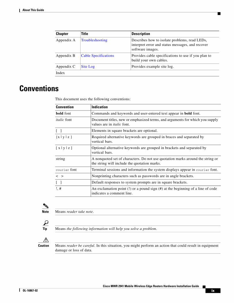
Chapter Title Description
Chapter 1 Introduction Describes the hardware features and specifications of the routers.
Chapter 2 Preparing to Install the Router Describes safety recommendations, site requirements, network connection considerations, required tools and equipment, and provides the installation checklist.
Chapter 3 Installing the Cisco MWR 2941 Router
Includes router installation information, and shows how to connect the router console/auxiliary port.
viiiCisco MWR 2941 Mobile Wireless Edge Routers Hardware Installation Guide
OL-16867-02
About This Guide
ConventionsThis document uses the following conventions:
Note Means reader take note.
Tip Means the following information will help you solve a problem.
Caution Means reader be careful. In this situation, you might perform an action that could result in equipment damage or loss of data.
Appendix A Troubleshooting Describes how to isolate problems, read LEDs, interpret error and status messages, and recover software images.
Appendix B Cable Specifications Provides cable specifications to use if you plan to build your own cables.
Appendix C Site Log Provides example site log.
Index
Chapter Title Description
Convention Indication
bold font Commands and keywords and user-entered text appear in bold font.
italic font Document titles, new or emphasized terms, and arguments for which you supply values are in italic font.
[ ] Elements in square brackets are optional.
{x | y | z } Required alternative keywords are grouped in braces and separated by vertical bars.
[ x | y | z ] Optional alternative keywords are grouped in brackets and separated by vertical bars.
string A nonquoted set of characters. Do not use quotation marks around the string or the string will include the quotation marks.
courier font Terminal sessions and information the system displays appear in courier font.
< > Nonprinting characters such as passwords are in angle brackets.
[ ] Default responses to system prompts are in square brackets.
!, # An exclamation point (!) or a pound sign (#) at the beginning of a line of code indicates a comment line.
ixCisco MWR 2941 Mobile Wireless Edge Routers Hardware Installation Guide
OL-16867-02
About This Guide
Timesaver Means the described action saves time. You can save time by performing the action described in the paragraph.
Warning Means reader be warned. In this situation, you might perform an action that could result in bodily injury.
Safety WarningsSafety warnings appear throughout this publication in procedures that, if performed incorrectly, might harm you. A warning symbol precedes each warning statement. The safety warnings provide safety guidelines that you should follow when working with any equipment that connects to electrical power or telephone wiring. Warnings are translated into several languages. (For information about compliance guidelines and translated safety warnings, refer to the Cisco Regulatory Compliance and Safety Information for the Cisco MWR 2941 Mobile Wireless Edge Router.)
Warning IMPORTANT SAFETY INSTRUCTIONS
This warning symbol means danger. You are in a situation that could cause bodily injury. Before you work on any equipment, be aware of the hazards involved with electrical circuitry and be familiar with standard practices for preventing accidents. Use the statement number provided at the end of each warning to locate its translation in the translated safety warnings that accompanied this device. Statement 1071
SAVE THESE INSTRUCTIONS
Waarschuwing BELANGRIJKE VEILIGHEIDSINSTRUCTIES
Dit waarschuwingssymbool betekent gevaar. U verkeert in een situatie die lichamelijk letsel kan veroorzaken. Voordat u aan enige apparatuur gaat werken, dient u zich bewust te zijn van de bij elektrische schakelingen betrokken risico's en dient u op de hoogte te zijn van de standaard praktijken om ongelukken te voorkomen. Gebruik het nummer van de verklaring onderaan de waarschuwing als u een vertaling van de waarschuwing die bij het apparaat wordt geleverd, wilt raadplegen.
BEWAAR DEZE INSTRUCTIES
Varoitus TÄRKEITÄ TURVALLISUUSOHJEITA
Tämä varoitusmerkki merkitsee vaaraa. Tilanne voi aiheuttaa ruumiillisia vammoja. Ennen kuin käsittelet laitteistoa, huomioi sähköpiirien käsittelemiseen liittyvät riskit ja tutustu onnettomuuksien yleisiin ehkäisytapoihin. Turvallisuusvaroitusten käännökset löytyvät laitteen mukana toimitettujen käännettyjen turvallisuusvaroitusten joukosta varoitusten lopussa näkyvien lausuntonumeroiden avulla.
SÄILYTÄ NÄMÄ OHJEET
xCisco MWR 2941 Mobile Wireless Edge Routers Hardware Installation Guide
OL-16867-02
About This Guide
Attention IMPORTANTES INFORMATIONS DE SÉCURITÉ
Ce symbole d'avertissement indique un danger. Vous vous trouvez dans une situation pouvant entraîner des blessures ou des dommages corporels. Avant de travailler sur un équipement, soyez conscient des dangers liés aux circuits électriques et familiarisez-vous avec les procédures couramment utilisées pour éviter les accidents. Pour prendre connaissance des traductions des avertissements figurant dans les consignes de sécurité traduites qui accompagnent cet appareil, référez-vous au numéro de l'instruction situé à la fin de chaque avertissement.
CONSERVEZ CES INFORMATIONS
Warnung WICHTIGE SICHERHEITSHINWEISE
Dieses Warnsymbol bedeutet Gefahr. Sie befinden sich in einer Situation, die zu Verletzungen führen kann. Machen Sie sich vor der Arbeit mit Geräten mit den Gefahren elektrischer Schaltungen und den üblichen Verfahren zur Vorbeugung vor Unfällen vertraut. Suchen Sie mit der am Ende jeder Warnung angegebenen Anweisungsnummer nach der jeweiligen Übersetzung in den übersetzten Sicherheitshinweisen, die zusammen mit diesem Gerät ausgeliefert wurden.
BEWAHREN SIE DIESE HINWEISE GUT AUF.
Avvertenza IMPORTANTI ISTRUZIONI SULLA SICUREZZA
Questo simbolo di avvertenza indica un pericolo. La situazione potrebbe causare infortuni alle persone. Prima di intervenire su qualsiasi apparecchiatura, occorre essere al corrente dei pericoli relativi ai circuiti elettrici e conoscere le procedure standard per la prevenzione di incidenti. Utilizzare il numero di istruzione presente alla fine di ciascuna avvertenza per individuare le traduzioni delle avvertenze riportate in questo documento.
CONSERVARE QUESTE ISTRUZIONI
Advarsel VIKTIGE SIKKERHETSINSTRUKSJONER
Dette advarselssymbolet betyr fare. Du er i en situasjon som kan føre til skade på person. Før du begynner å arbeide med noe av utstyret, må du være oppmerksom på farene forbundet med elektriske kretser, og kjenne til standardprosedyrer for å forhindre ulykker. Bruk nummeret i slutten av hver advarsel for å finne oversettelsen i de oversatte sikkerhetsadvarslene som fulgte med denne enheten.
TA VARE PÅ DISSE INSTRUKSJONENE
Aviso INSTRUÇÕES IMPORTANTES DE SEGURANÇA
Este símbolo de aviso significa perigo. Você está em uma situação que poderá ser causadora de lesões corporais. Antes de iniciar a utilização de qualquer equipamento, tenha conhecimento dos perigos envolvidos no manuseio de circuitos elétricos e familiarize-se com as práticas habituais de prevenção de acidentes. Utilize o número da instrução fornecido ao final de cada aviso para localizar sua tradução nos avisos de segurança traduzidos que acompanham este dispositivo.
GUARDE ESTAS INSTRUÇÕES
xiCisco MWR 2941 Mobile Wireless Edge Routers Hardware Installation Guide
OL-16867-02
About This Guide
¡Advertencia! INSTRUCCIONES IMPORTANTES DE SEGURIDAD
Este símbolo de aviso indica peligro. Existe riesgo para su integridad física. Antes de manipular cualquier equipo, considere los riesgos de la corriente eléctrica y familiarícese con los procedimientos estándar de prevención de accidentes. Al final de cada advertencia encontrará el número que le ayudará a encontrar el texto traducido en el apartado de traducciones que acompaña a este dispositivo.
GUARDE ESTAS INSTRUCCIONES
Varning! VIKTIGA SÄKERHETSANVISNINGAR
Denna varningssignal signalerar fara. Du befinner dig i en situation som kan leda till personskada. Innan du utför arbete på någon utrustning måste du vara medveten om farorna med elkretsar och känna till vanliga förfaranden för att förebygga olyckor. Använd det nummer som finns i slutet av varje varning för att hitta dess översättning i de översatta säkerhetsvarningar som medföljer denna anordning.
SPARA DESSA ANVISNINGAR
xiiCisco MWR 2941 Mobile Wireless Edge Routers Hardware Installation Guide
OL-16867-02
About This Guide
Aviso INSTRUÇÕES IMPORTANTES DE SEGURANÇA
Este símbolo de aviso significa perigo. Você se encontra em uma situação em que há risco de lesões corporais. Antes de trabalhar com qualquer equipamento, esteja ciente dos riscos que envolvem os circuitos elétricos e familiarize-se com as práticas padrão de prevenção de acidentes. Use o número da declaração fornecido ao final de cada aviso para localizar sua tradução nos avisos de segurança traduzidos que acompanham o dispositivo.
GUARDE ESTAS INSTRUÇÕES
Advarsel VIGTIGE SIKKERHEDSANVISNINGER
Dette advarselssymbol betyder fare. Du befinder dig i en situation med risiko for legemesbeskadigelse. Før du begynder arbejde på udstyr, skal du være opmærksom på de involverede risici, der er ved elektriske kredsløb, og du skal sætte dig ind i standardprocedurer til undgåelse af ulykker. Brug erklæringsnummeret efter hver advarsel for at finde oversættelsen i de oversatte advarsler, der fulgte med denne enhed.
GEM DISSE ANVISNINGER
xiiiCisco MWR 2941 Mobile Wireless Edge Routers Hardware Installation Guide
OL-16867-02
About This Guide
xivCisco MWR 2941 Mobile Wireless Edge Routers Hardware Installation Guide
OL-16867-02
About This Guide
Related DocumentationFor additional information about the Cisco MWR 2941 router, refer to the following documents:
• Cisco Regulatory Compliance and Safety Information for the Cisco MWR 2941 Mobile Wireless Edge Router
• Cisco MWR 2941 Mobile Wireless Edge Router Software Configuration Guide
• Release Notes for Cisco MWR 2941 Mobile Wireless Edge Router
Obtaining Documentation, Obtaining Support, and Security Guidelines
For information on obtaining documentation, obtaining support, providing documentation feedback, security guidelines, and also recommended aliases and general Cisco documents, see the monthly What’s New in Cisco Product Documentation, which also lists all new and revised Cisco technical documentation, at:
http://www.cisco.com/en/US/docs/general/whatsnew/whatsnew.html
xvCisco MWR 2941 Mobile Wireless Edge Routers Hardware Installation Guide
OL-16867-02

About This Guide
xviCisco MWR 2941 Mobile Wireless Edge Routers Hardware Installation Guide
OL-16867-02
Cisco MWR 2941 Mobile WOL-16867-02
C H A P T E R 1
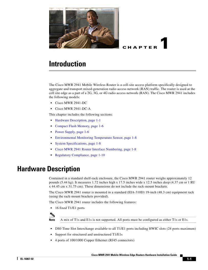
IntroductionThe Cisco MWR 2941 Mobile Wireless Router is a cell-site access platform specifically designed to aggregate and transport mixed-generation radio access network (RAN) traffic. The router is used at the cell site edge as a part of a 2G, 3G, or 4G radio access network (RAN). The Cisco MWR 2941 includes the following models:
• Cisco MWR 2941-DC
• Cisco MWR 2941-DC-A
This chapter includes the following sections:
• Hardware Description, page 1-1
• Compact Flash Memory, page 1-6
• Power Supply, page 1-6
• Environmental Monitoring Temperature Sensor, page 1-8
• System Specifications, page 1-8
• Cisco MWR 2941 Router Interface Numbering, page 1-8
• Regulatory Compliance, page 1-10
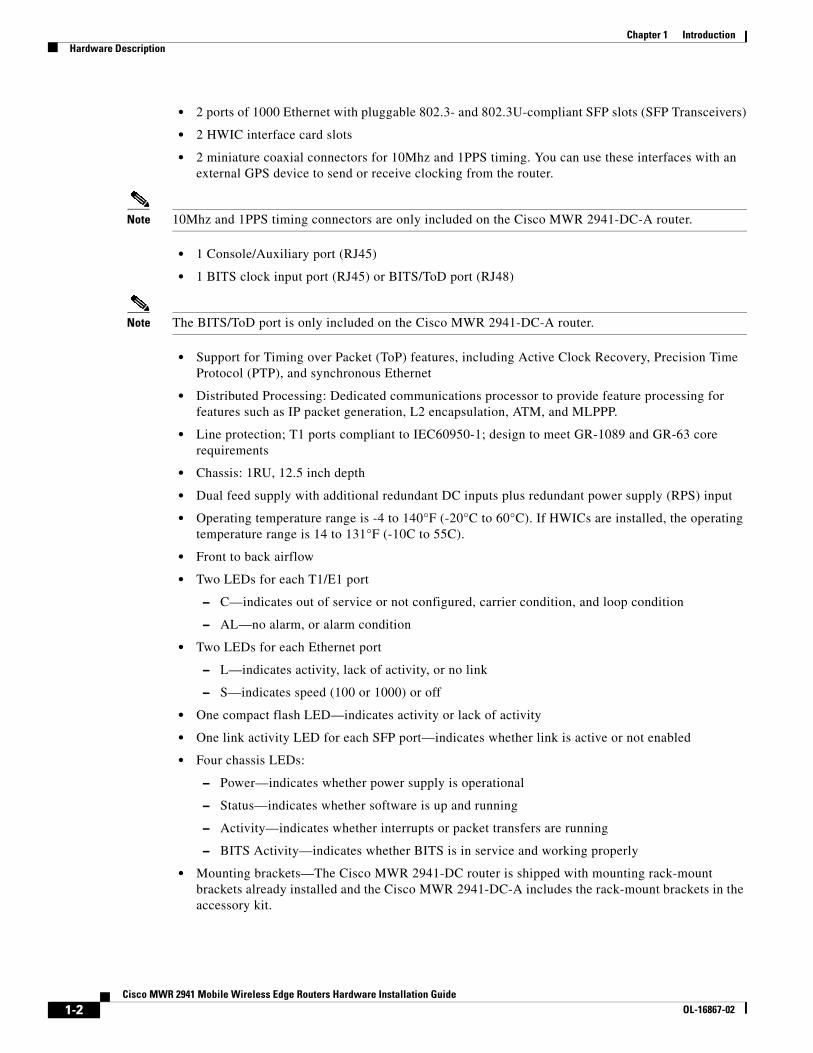
Hardware DescriptionContained in a standard shelf-rack enclosure, the Cisco MWR 2941 router weighs approximately 12 pounds (5.44 kg). It measures 1.72 inches high x 17.5 inches wide x 12.5 inches deep (4.37 cm or 1 RU x 44.45 cm x 31.75 cm). These dimensions do not include the rack-mount brackets.
The Cisco MWR 2941 router is mounted in a standard (EIA-310D) 19-inch (48.3 cm) equipment rack (using the rack-mount brackets provided).
The Cisco MWR 2941 router includes the following features:
• 16 fixed T1/E1 ports
Note A mix of T1s and E1s is not supported. All ports must be configured as either T1s or E1s.
• DS0 Time Slot Interchange available to all T1/E1 ports including HWIC slots (24 ports maximum)
• Support for structured and unstructured T1/E1s
• 4 ports of 100/1000 Copper Ethernet (RJ45 connectors)
1-1ireless Edge Routers Hardware Installation Guide
Chapter 1 IntroductionHardware Description
• 2 ports of 1000 Ethernet with pluggable 802.3- and 802.3U-compliant SFP slots (SFP Transceivers)
• 2 HWIC interface card slots
• 2 miniature coaxial connectors for 10Mhz and 1PPS timing. You can use these interfaces with an external GPS device to send or receive clocking from the router.
Note 10Mhz and 1PPS timing connectors are only included on the Cisco MWR 2941-DC-A router.
• 1 Console/Auxiliary port (RJ45)
• 1 BITS clock input port (RJ45) or BITS/ToD port (RJ48)
Note The BITS/ToD port is only included on the Cisco MWR 2941-DC-A router.
• Support for Timing over Packet (ToP) features, including Active Clock Recovery, Precision Time Protocol (PTP), and synchronous Ethernet
• Distributed Processing: Dedicated communications processor to provide feature processing for features such as IP packet generation, L2 encapsulation, ATM, and MLPPP.
• Line protection; T1 ports compliant to IEC60950-1; design to meet GR-1089 and GR-63 core requirements
• Chassis: 1RU, 12.5 inch depth
• Dual feed supply with additional redundant DC inputs plus redundant power supply (RPS) input
• Operating temperature range is -4 to 140°F (-20°C to 60°C). If HWICs are installed, the operating temperature range is 14 to 131°F (-10C to 55C).
• Front to back airflow
• Two LEDs for each T1/E1 port
– C—indicates out of service or not configured, carrier condition, and loop condition
– AL—no alarm, or alarm condition
• Two LEDs for each Ethernet port
– L—indicates activity, lack of activity, or no link
– S—indicates speed (100 or 1000) or off
• One compact flash LED—indicates activity or lack of activity
• One link activity LED for each SFP port—indicates whether link is active or not enabled
• Four chassis LEDs:
– Power—indicates whether power supply is operational
– Status—indicates whether software is up and running
– Activity—indicates whether interrupts or packet transfers are running
– BITS Activity—indicates whether BITS is in service and working properly
• Mounting brackets—The Cisco MWR 2941-DC router is shipped with mounting rack-mount brackets already installed and the Cisco MWR 2941-DC-A includes the rack-mount brackets in the accessory kit.
1-2Cisco MWR 2941 Mobile Wireless Edge Routers Hardware Installation Guide
OL-16867-02
Chapter 1 IntroductionHardware Description
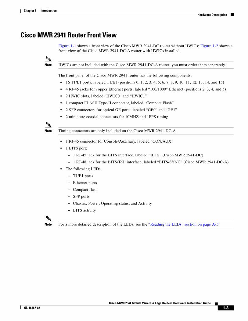
Cisco MWR 2941 Router Front ViewFigure 1-1 shows a front view of the Cisco MWR 2941-DC router without HWICs; Figure 1-2 shows a front view of the Cisco MWR 2941-DC-A router with HWICs installed.
Note HWICs are not included with the Cisco MWR 2941-DC-A router; you must order them separately.
The front panel of the Cisco MWR 2941 router has the following components:
• 16 T1/E1 ports, labeled T1/E1 (positions 0, 1, 2, 3, 4, 5, 6, 7, 8, 9, 10, 11, 12, 13, 14, and 15)
• 4 RJ-45 jacks for copper Ethernet ports, labeled “100/1000” Ethernet (positions 2, 3, 4, and 5)
• 2 HWIC slots, labeled “HWIC0” and “HWIC1”
• 1 compact FLASH Type-II connector, labeled “Compact Flash”
• 2 SFP connectors for optical GE ports, labeled “GE0” and “GE1”
• 2 miniature coaxial connectors for 10MHZ and 1PPS timing
Note Timing connectors are only included on the Cisco MWR 2941-DC-A.
• 1 RJ-45 connector for Console/Auxiliary, labeled “CON/AUX”
• 1 BITS port:
– 1 RJ-45 jack for the BITS interface, labeled “BITS” (Cisco MWR 2941-DC)
– 1 RJ-48 jack for the BITS/ToD interface, labeled “BITS/SYNC” (Cisco MWR 2941-DC-A)
• The following LEDs
– T1/E1 ports
– Ethernet ports
– Compact flash
– SFP ports
– Chassis: Power, Operating status, and Activity
– BITS activity
Note For a more detailed description of the LEDs, see the “Reading the LEDs” section on page A-5.
1-3Cisco MWR 2941 Mobile Wireless Edge Routers Hardware Installation Guide
OL-16867-02
Chapter 1 IntroductionHardware Description
Figure 1-1 Cisco MWR 2941-DC Router—Front View
Figure 1-2 Cisco MWR 2941-DC-A Router—Front View
Note The HWICs shown in Figure 1-2 are not included with the Cisco MWR 2941-DC-A router; you must order them separately.
2743
09
Console/Auxiliary port
16 T1/E1 ports Compactflash slot
Compactflash LED
Link ActivityLEDs
PowerStatusActivityBITS Activity
Chassis LEDs
4 GE ports(RJ45 100/1000
Ethernet)
2 GE ports(SFP 1000BT)
BITSport
2520
32
Console/Auxiliary port
16 T1/E1 ports Compactflash slot
Compactflash LED
Link ActivityLEDs
PowerStatusActivityBITS Activity
Chassis LEDs
4 GE ports(RJ45 100/1000
Ethernet) 2 GE ports(SFP 1000BT)
BITS/SYNCport
2 Mini-coaxconnectors
(10MHZ and 1PPS)
1-4Cisco MWR 2941 Mobile Wireless Edge Routers Hardware Installation Guide
OL-16867-02
Chapter 1 IntroductionHardware Description
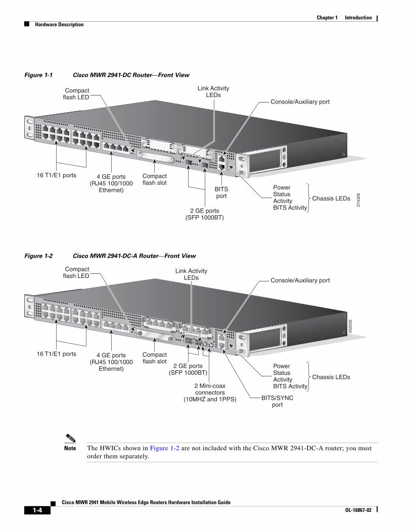
Cisco MWR 2941 Rear ViewFigure 1-3 shows the rear panel of the Cisco MWR 2941 router, including the orientation of the following components:
• Four exhaust fans
• Mounting point for 2-hole lug. For more information, see the “Connecting the Chassis Ground and Power” section on page 3-6.
• Cisco MWR 2941 router power connector. For more information, see the “Wiring the DC-Input Power Source” section on page 3-9.
Figure 1-3 Cisco MWR 2941 Router Rear View
Hardware Configuration OptionsThe Cisco MWR 2941 router supports has the following hardware configuration options:
• HWIC Cards
• SFP Modules
HWIC Cards
Two HWIC slots allow you to configure the chassis with any two supported HWIC interface cards. HWIC support varies according to the software version installed on the router. The HWIC slots are labeled HWIC0 and HWIC1 on the faceplate of the Cisco MWR 2941 router. The HWIC slots can accommodate 2 T1/E1 HWICs, expanding the number of T1/E1 ports from 16 to 24 ports. You can configure HWIC T1/E1 ports for use as a GSM short-haul connection or an IP RAN backhaul connection.
To see the HWICs supported for a given software version, see the MWR 2941 Release Notes at http://www.cisco.com/en/US/products/ps9395/prod_release_notes_list.html. For information about how to install HWICs, see http://www.cisco.com/en/US/products/ps5949/tsd_products_support_series_home.html.
Power connector
Fan
Grounding point for 2-hole lug
2809
26
1-5Cisco MWR 2941 Mobile Wireless Edge Routers Hardware Installation Guide
OL-16867-02
Chapter 1 IntroductionCompact Flash Memory
Note The Cisco MWR 2941 does not support online insertion and removal (OIR) of HWIC interface cards. Attempts to perform OIR on a card in a powered-on router might cause damage to the card.
SFP Modules
Two SFP ports allow you to configure the Ethernet ports according to the needs of your network. SFP support varies according to the software version installed on the router. To see the SFPs supported for a given software version, see the MWR 2941 Release Notes at http://www.cisco.com/en/US/products/ps9395/prod_release_notes_list.html.
Compact Flash MemoryThe Cisco MWR 2941 router supports one compact flash slot on the front panel. The slot is intended to house a memory card using the compact flash standard file system. The most common usage is for storage of the system image or core dumps for diagnostic purposes. The Cisco IOS image and troubleshooting logs reside on the flash memory.
This compact flash device is not field upgradeable, it is only installed at the factory.
The front panel connector supports both Type I and Type II 3.3V Compact Flash devices. The compact flash controller has the following features:
• Operating mode: PCMCIA-compatible PC card in memory mode
• Auto power removal on removal of compact flash from the slot
• Write protection
• Support Cisco qualified 128MB compact flash devices
Note The interface supports any size compact flash device. The size limit is a statement on test coverage and qualification time limits.
Please refer to the industry standard for compact flash for details on internal registers. All compact flash follow the ATA standard for internal register access.
Power SupplyThe Cisco MWR -DC router is equipped with an Internal +27/-48 volts Direct Current (VDC) (±20 to 60 VDC supply tolerance).
Safety PrecautionsObserve the following general safety precautions and recommendations in planning the source power requirements for the Cisco MWR 2941 router (for additional safety information, see the “Safety Guidelines” section on page 2-1):
• Check the power at your site before router installation (and periodically after installation) to ensure clean power (free of spikes and noise) is being received.
1-6Cisco MWR 2941 Mobile Wireless Edge Routers Hardware Installation Guide
OL-16867-02
Chapter 1 IntroductionPower Supply
• Always disconnect the power source and unplug the power cable before working on the router.
• Install proper grounding for the site to avoid damage from lightning and power surges.
Warning To avoid electric shock, do not connect safety extra-low voltage (SELV) circuits to telephone-network voltage (TNV) circuits. LAN ports contain SELV circuits, and WAN ports contain TNV circuits. Some LAN and WAN ports both use RJ-45 connectors. Use caution when connecting cables. Statement 1021
Table 1-1 lists DC power supply specifications for the Cisco MWR 2941 router.
The Cisco MWR 2941 router uses a 4-pin terminal block (part number 27-2030-01) for input to the power supply. The terminal block is part of the accessory kit (part number 53-3085-01 for the MWR-2941-DC, part number 53-3295-01 for the MWR-2941-DC-A), which ships with the Cisco MWR 2941 router.
Note that the ground wire connects to a 2-hole lug, which connects to the corresponding mounting point.
With the connector installed in the chassis, the pins are for two separate input power sources named A and B. From left to right, the pins are for rail A+, rail A-, rail B-, and rail B+.
Table 1-2 and Table 1-3 list the pinout configurations for the connector, based on the power source.
Table 1-1 Cisco MWR 2941 Router Power Supply Specifications
Specification +27/-48 VDC
Input voltage, DC power supply Maximum input current
Note If the input voltage drops below 18.5 VDC, the router goes into shut down mode.
±20 to 60 VDC 3.5 A (current rating = 4 A)
Wire gauge for DC input power connections
18-AWG
Power dissipation 65 W (maximum), 45 W (typical)
Table 1-2 Power Supply Connector Pinouts (+27 VDC Application)
Pin +27 VDC Power Source
1 +27 VDC A
2 RTN A
3 RTN B
4 +27 VDC B
1-7Cisco MWR 2941 Mobile Wireless Edge Routers Hardware Installation Guide
OL-16867-02
Chapter 1 IntroductionEnvironmental Monitoring Temperature Sensor
Environmental Monitoring Temperature SensorThe Cisco MWR 2941 router has a temperature sensor to detect overtemperature conditions inside the chassis. The overtemperature detection trips at 70°C +/- 5%. This condition is reported to the processor as an interrupt, where software takes action to generate the appropriate alarms.
System SpecificationsTable 1-4 lists the system specifications for Cisco MWR 2941 router.
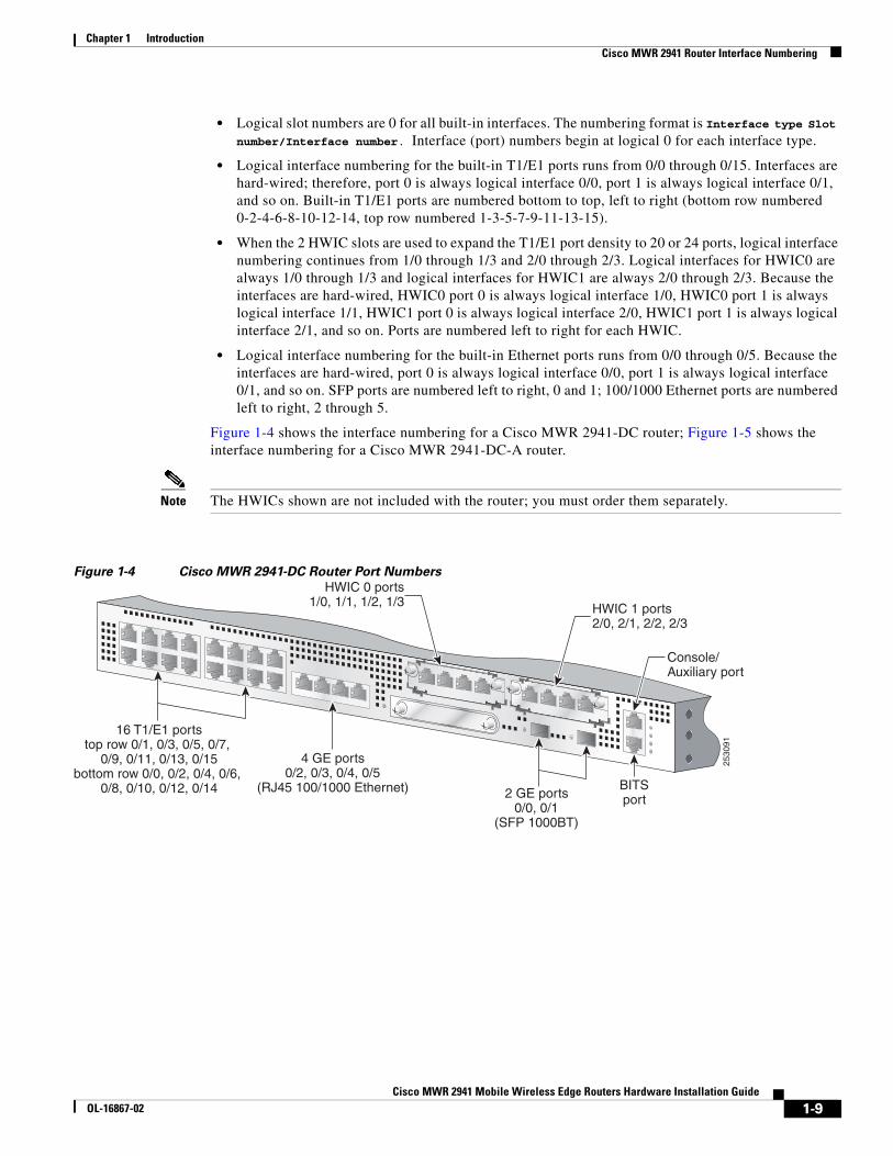
Cisco MWR 2941 Router Interface NumberingEach network interface on a Cisco MWR 2941 router is identified by a slot number and a port number.
Following is an explanation of the slot/port numbering:
Table 1-3 Power Supply Connector Pinouts (-48 VDC Application)
Pin -48 VDC Power Source
1 RTN A
2 -48 VDC A
3 -48 VDC B
4 RTN B
Table 1-4 Cisco MWR 2941 Router System Specifications
Description Specification
Dimensions (H x W x D) 1.72 x 17.5 x 12.5 in. (4.37 x 44.45 x 31.75 cm) 1 RU (rack unit) in a 19-inch (48.3 cm) rack
Weight 12 lb (5.44 kg)
Console and Auxiliary ports RJ-45 connector
Operating Temperature Operating temperature range is -4 to 140°F (-20°C to 60°C). If HWICs are installed, the operating temperature range is 14 to 131°F (-10C to 55C).
Non-Operational Temperature -40 to 185°F (-40 to 85°C)
Operating Humidity 5 to 90% RH (non-condensing)
Operating Altitude 9,842.5 ft. (3000 m) at 113°F (45°C)
Operating Vibration 0.41 Grms, 3 to 500 Hz/2 hr. per axis GR-63-CORE earthquake resistance, Zone 4, shelf-level
Non-Operational Vibration 1.12 Grms, 3 to 500 Hz/30 min. per axis
Operating Acoustics <63.5 dBa
1-8Cisco MWR 2941 Mobile Wireless Edge Routers Hardware Installation Guide
OL-16867-02
Chapter 1 IntroductionCisco MWR 2941 Router Interface Numbering
• Logical slot numbers are 0 for all built-in interfaces. The numbering format is Interface type Slot number/Interface number. Interface (port) numbers begin at logical 0 for each interface type.
• Logical interface numbering for the built-in T1/E1 ports runs from 0/0 through 0/15. Interfaces are hard-wired; therefore, port 0 is always logical interface 0/0, port 1 is always logical interface 0/1, and so on. Built-in T1/E1 ports are numbered bottom to top, left to right (bottom row numbered 0-2-4-6-8-10-12-14, top row numbered 1-3-5-7-9-11-13-15).
• When the 2 HWIC slots are used to expand the T1/E1 port density to 20 or 24 ports, logical interface numbering continues from 1/0 through 1/3 and 2/0 through 2/3. Logical interfaces for HWIC0 are always 1/0 through 1/3 and logical interfaces for HWIC1 are always 2/0 through 2/3. Because the interfaces are hard-wired, HWIC0 port 0 is always logical interface 1/0, HWIC0 port 1 is always logical interface 1/1, HWIC1 port 0 is always logical interface 2/0, HWIC1 port 1 is always logical interface 2/1, and so on. Ports are numbered left to right for each HWIC.
• Logical interface numbering for the built-in Ethernet ports runs from 0/0 through 0/5. Because the interfaces are hard-wired, port 0 is always logical interface 0/0, port 1 is always logical interface 0/1, and so on. SFP ports are numbered left to right, 0 and 1; 100/1000 Ethernet ports are numbered left to right, 2 through 5.
Figure 1-4 shows the interface numbering for a Cisco MWR 2941-DC router; Figure 1-5 shows the interface numbering for a Cisco MWR 2941-DC-A router.
Note The HWICs shown are not included with the router; you must order them separately.
Figure 1-4 Cisco MWR 2941-DC Router Port Numbers
HWIC 0 ports1/0, 1/1, 1/2, 1/3
Console/ Auxiliary port
16 T1/E1 ports top row 0/1, 0/3, 0/5, 0/7,
0/9, 0/11, 0/13, 0/15 bottom row 0/0, 0/2, 0/4, 0/6,
0/8, 0/10, 0/12, 0/14
4 GE ports 0/2, 0/3, 0/4, 0/5
(RJ45 100/1000 Ethernet) 2 GE ports 0/0, 0/1
(SFP 1000BT)
2530
91
BITS port
HWIC 1 ports2/0, 2/1, 2/2, 2/3
1-9Cisco MWR 2941 Mobile Wireless Edge Routers Hardware Installation Guide
OL-16867-02
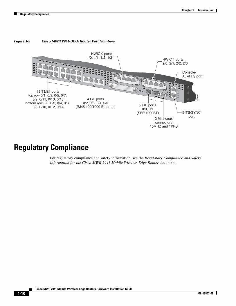
Chapter 1 IntroductionRegulatory Compliance
Figure 1-5 Cisco MWR 2941-DC-A Router Port Numbers
Regulatory ComplianceFor regulatory compliance and safety information, see the Regulatory Compliance and Safety Information for the Cisco MWR 2941 Mobile Wireless Edge Router document.
HWIC 0 ports1/0, 1/1, 1/2, 1/3
Console/ Auxiliary port
16 T1/E1 ports top row 0/1, 0/3, 0/5, 0/7,
0/9, 0/11, 0/13, 0/15 bottom row 0/0, 0/2, 0/4, 0/6,
0/8, 0/10, 0/12, 0/14
4 GE ports0/2, 0/3, 0/4, 0/5
(RJ45 100/1000 Ethernet) 2 GE ports0/0, 0/1
(SFP 1000BT) BITS/SYNCport
HWIC 1 ports2/0, 2/1, 2/2, 2/3
2520
31
2 Mini-coaxconnectors
10MHZ and 1PPS
1-10Cisco MWR 2941 Mobile Wireless Edge Routers Hardware Installation Guide
OL-16867-02
Cisco MWR 2941 Mobile WOL-16867-02
C H A P T E R 2
Preparing to Install the RouterThis chapter describes site requirements and equipment used to install your Cisco MWR 2941 router. It includes the following sections:
• Safety Guidelines, page 2-1
• Prerequisites, page 2-3
• Site Planning, page 2-4
• Console/Auxiliary Port Considerations, page 2-8
Safety GuidelinesBefore you begin the installation of the Cisco MWR 2941 router, review the safety guidelines in this chapter, the “Safety Precautions” section on page 1-6, and the “Rack-Mounting Configuration Guidelines” section on page 3-2 to avoid injuring yourself or damaging the equipment.
In addition, before replacing, configuring, or maintaining the Cisco MWR 2941 router, review the safety warnings listed in the document Cisco Regulatory Compliance and Safety Information for the Cisco MWR 2941 Mobile Wireless Edge Router.
Safety with EquipmentThe following guidelines help ensure your safety and protect the equipment. This list is not all- inclusive of all potentially hazardous situations, so be alert.
Warning Before connecting the system to the power source, read the installation instructions. Statement 1004
• Before moving the system, always disconnect all power cords and interface cables.
• Never assume that power is disconnected from a circuit; always check.
• Before and after installation, keep the chassis area clear and dust-free.
• Keep tools and assembly components away from walk areas where you or others could fall over them.
• Do not work alone if potentially hazardous conditions exist.
• Do not perform any action that creates a potential hazard to people or makes the equipment unsafe.
• Do not wear loose clothing that may get caught in the chassis.
2-1ireless Edge Routers Hardware Installation Guide
Chapter 2 Preparing to Install the RouterSafety Guidelines
• When working under conditions that may be hazardous to your eyes, wear safety glasses.
Safety with Electricity
Warning Before performing any of the following procedures, ensure that power is removed from the DC circuit. Statement 1003
Warning This unit is intended for installation in restricted access areas. A restricted access area can be accessed only through the use of a special tool, lock and key, or other means of security. Statement 1017
Warning To avoid electric shock, do not connect safety extra-low voltage (SELV) circuits to telephone-network voltage (TNV) circuits. LAN ports contain SELV circuits, and WAN ports contain TNV circuits. Some LAN and WAN ports both use RJ-45 connectors. Statement 1021
Warning Before working on equipment that is connected to power lines, remove jewelry (including rings, necklaces, and watches). Metal objects will heat up when connected to power and ground and can cause serious burns or weld the metal object to the terminals. Statement 43
Warning Before working on a chassis or working near power supplies, unplug the power cord on AC units; disconnect the power at the circuit breaker on DC units. Statement 12
Warning During periods of lightning activity, do not work on the system or connect or disconnect cables. Statement 1001
When working on equipment powered by electricity, follow these guidelines:
• Locate the room’s emergency power-off switch. Then, if an electrical accident occurs, you can quickly turn off the power.
• Before working on the system, turn off the DC main circuit breaker and disconnect the power terminal block cable.
• Before doing the following, disconnect all power:
– Working on or near power supplies
– Installing or removing a router chassis or network processor module
– Performing most hardware upgrades
• Never install equipment that appears damaged.
• Carefully examine your work area for possible hazards, such as moist floors, ungrounded power extension cables, and missing safety grounds.
• Never assume that power is disconnected from a circuit; always check.
• Never perform any action that creates a potential hazard to people or makes the equipment unsafe.
2-2Cisco MWR 2941 Mobile Wireless Edge Routers Hardware Installation Guide
OL-16867-02
Chapter 2 Preparing to Install the RouterPrerequisites
• If an electrical accident occurs, proceed as follows:
– Use caution, and do not become a victim yourself.
– Turn off power to the router.
– If possible, send another person to get medical aid. Otherwise, determine the condition of the victim, and then call for help.
– Determine whether the person needs rescue breathing or external cardiac compressions; then take appropriate action.
In addition, use the following guidelines when working with any equipment that is disconnected from a power source, but still connected to telephone wiring or network cabling:
• Never install telephone wiring during a lightning storm.
• Never install telephone jacks in wet locations unless the jack is specifically designed for it.
• Never touch un-insulated telephone wires or terminals unless the telephone line is disconnected at the network interface.
• When installing or modifying telephone lines, use caution.
Preventing Electrostatic Discharge DamageElectrostatic discharge (ESD) can damage equipment and impair electrical circuitry. ESD can occur when electronic printed circuit cards are improperly handled and can cause complete or intermittent failures. When removing and replacing modules, always follow ESD prevention procedures:
• Ensure that the router chassis is electrically connected to earth ground.
• Wear an ESD-preventive wrist strap, ensuring that it makes good skin contact. To channel unwanted ESD voltages safely to ground, connect the clip to an unpainted surface of the chassis frame. To guard against ESD damage and shocks, the wrist strap and cord must operate effectively.
• If no wrist strap is available, ground yourself by touching a metal part of the chassis.
Caution For the safety of your equipment, periodically check the resistance value of the antistatic wrist strap. It should be between 1 and 10 Mohm.
PrerequisitesBefore installing the Cisco MWR 2941 router, it is important to prepare for installation by:
• Preparing the site (site planning) and reviewing the installation plans or method of procedures (MOPs)
• Unpacking and inspecting the Cisco MWR 2941 router
• Gathering tools and test equipment required to properly install the Cisco MWR 2941 router
2-3Cisco MWR 2941 Mobile Wireless Edge Routers Hardware Installation Guide
OL-16867-02
Chapter 2 Preparing to Install the RouterSite Planning
Site PlanningTypically, you should have prepared the installation site beforehand. As part of your preparation, obtain a floor plan of the site and the equipment rack where the Cisco MWR 2941 router will be housed. Determine the location of any existing routers and their interconnections, including communications and power. Following the air flow guidelines (see the “Air Flow Guidelines” section on page 2-4) ensures that adequate cooling air is provided to the Cisco MWR 2941 router.
All personnel involved in the installation of the Cisco MWR 2941 router including installers, engineers, and supervisors should participate in the preparation of a MOP for approval by the customer.
Power Supply ConsiderationsCheck the power at your site to ensure that you are receiving clean power (free of spikes and noise). Install a power conditioner if necessary (see the “Power Supply” section on page 1-6 for power requirements).
Warning This equipment is designed for connection to TN and IT power systems. Statement 16
Site EnvironmentInstall the Cisco MWR 2941 router in an equipment rack. The location of your router and the layout of your equipment rack or wiring room are extremely important considerations for proper operation. Cramped equipment, inadequate ventilation, and inaccessible panels can cause malfunctions and shutdowns, and can make maintenance difficult. Plan for access to front and rear panels of the router.
The following precautions will help you plan an acceptable operating environment for your router and will help you avoid environmentally caused equipment failures:
• Ensure that the room where your router operates has adequate circulation. Electrical equipment generates heat. Without adequate circulation, ambient air temperature may not cool equipment to acceptable operating temperatures (see the next section, “Air Flow Guidelines”).
• Always follow ESD-prevention procedures described in the “Preventing Electrostatic Discharge Damage” section on page 2-3 to avoid damage to equipment. Damage from static discharge can cause immediate or intermittent equipment failure.
Air Flow GuidelinesTo ensure adequate air flow through the equipment rack, it is recommended that you maintain a clearance of at least 6 inches (15.24 cm) in the front and the rear of the rack at all times.
If airflow through the equipment rack and the routers that occupy it is blocked or restricted, or if the ambient air being drawn into the rack is too warm, an overtemperature condition within the rack and the routers that occupy it can occur.
The site should also be as dust-free as possible. Dust tends to clog the router fans, reducing the flow of cooling air through the equipment rack and the routers that occupy it. Thus, increasing the risk of an overtemperature condition.
Additionally, the following guidelines will help you plan your equipment rack configuration:
2-4Cisco MWR 2941 Mobile Wireless Edge Routers Hardware Installation Guide
OL-16867-02
Chapter 2 Preparing to Install the RouterSite Planning
• Mount the Cisco MWR 2941 router in a 19-inch rack (with a 17.5- or 17.75-inch opening).
• Beside air flow, you must allow clearance around the rack for maintenance.
• Enclosed racks must have adequate ventilation. Ensure that the rack is not congested, because each router generates heat. An enclosed rack should have louvered sides and a fan to provide cooling air. Heat that is generated by equipment near the bottom of the rack can be drawn upward into the intake ports of the equipment above.
• When mounting a chassis in an open rack, ensure that the rack frame does not block the front intakes or the rear exhaust fans.
• When rack-installed equipment fails, especially equipment in an enclosed rack, try operating the equipment by itself, if possible. Power off other equipment in the rack (and in adjacent racks) to give the router a maximum of cooling air and clean power.
Method of ProcedurePart of site preparation includes reviewing installation plans or MOPs. An example of a MOP (pre-installation checklist of tasks and considerations to address and agree upon before proceeding with the installation) is as follows:
1. Assign personnel.
2. Determine protection requirements for personnel, equipment, and tools.
3. Evaluate potential hazards that may affect service.
4. Schedule time for installation.
5. Determine space requirements.
6. Determine power requirements.
7. Identify required procedures or tests.
8. On an equipment plan, make a preliminary decision that locates each Cisco MWR 2941 router that you plan to install.
9. Read this hardware installation guide.
10. Verify the list of replaceable parts for installation (screws, bolts, washers, and so on) so that the parts are identified.
11. Check the required tools list to make sure the necessary tools and test equipment are available (see the “Required Tools and Equipment” section on page 2-6).
12. Perform the installation.
Unpacking and Checking the Contents of your ShipmentThe shipping package for the Cisco MWR 2941 router is designed to reduce the possibility of product damage associated with routine handling experienced during shipment. To reduce the potential damage to the product, transport the Cisco MWR 2941 router in its Cisco specified packaging. Failure to do so may result in damage to the Cisco MWR 2941 router. Also do not remove the Cisco MWR 2941 router from its shipping container until you are ready to install it.
Note Do not discard the packaging materials used in shipping your Cisco MWR 2941 router. You will need the packaging materials in the future if you move or ship your Cisco MWR 2941 router.
2-5Cisco MWR 2941 Mobile Wireless Edge Routers Hardware Installation Guide
OL-16867-02
Chapter 2 Preparing to Install the RouterSite Planning
The Cisco MWR 2941 router, cables, and any optional equipment you ordered may be shipped in more than one container. When you unpack the containers, check the packing list to ensure that you receive all of the following items:
• Router
• Accessory kit (part number 53-3085-01 for the MWR-2941-DC, part number 53-3295-01 for the MWR-2941-DC-A), containing
– Terminal block (part number 27-2030-01)
– 2-hole lug, 6-AWG ground wire, #10 blue stud (part number 32-0629-01)
– 2 pan-head Phillips screws used to attach the lug to the router, M5.0x10mm (part number 48-0426-01)
– 2 cable guides (part number 700-01663-01)
– 2 pan-head Phillips screws used to attach the cable guides, M4,0x20mm (part number 48-0654-01)
Note There is no AC power option.
• The documentation DVD, if specified in your order
• Cisco Information Packet publication
Inspect all items for shipping damage. If an item appears to be damaged, or if you encounter problems installing or configuring your router, contact customer service. The Cisco Information Packet provides warranty, service, and support information.
Required Tools and EquipmentYou need the following tools and equipment to install and upgrade the router and its components:
Warning Only trained and qualified personnel should be allowed to install or replace this equipment. Statement 49
• ESD-preventive cord and wrist strap.
• Number 2 Phillips screwdriver.
• Flat-blade screwdrivers: small, 3/16-inch (0.476 cm) and medium, 1/4-inch (0.625 cm).
– To install or remove modules
– To remove the cover, if you are upgrading memory or other components
• #12-24 pan-head screws to secure the router to the equipment rack.
• Cables for connection to the WAN and LAN ports (depending on the configuration).
Note For more information on cable specifications, see Appendix B, “Cable Specifications.”
• Ethernet hub or PC with a network interface card for connection to the Ethernet (LAN) ports.
• Console terminal (an ASCII terminal or a PC running terminal emulation software) that is configured for 9600 baud, 8 data bits, no parity, and 2 stop bits.
2-6Cisco MWR 2941 Mobile Wireless Edge Routers Hardware Installation Guide
OL-16867-02
Chapter 2 Preparing to Install the RouterSite Planning
• Console cable for connection to the console port.
• Modem for connection to the auxiliary port for remote administrative access (optional).
• Auxiliary cable for connection to the auxiliary port. You can supply this cable or order one from Cisco Systems, Inc.
• Ratcheting torque screwdriver with a Phillips head that exerts up to 15 pound-force inches (lbf-in) of pressure.
• Crimping tool as specified by the ground lug manufacturer.
• 18-AWG copper wire for the power cord.
• Wire-stripping tools for stripping both 6- and 18-AWG wire.
• Serial interfaces may require a data service unit (DSU) or channel service unit/data service unit (CSU/DSU).
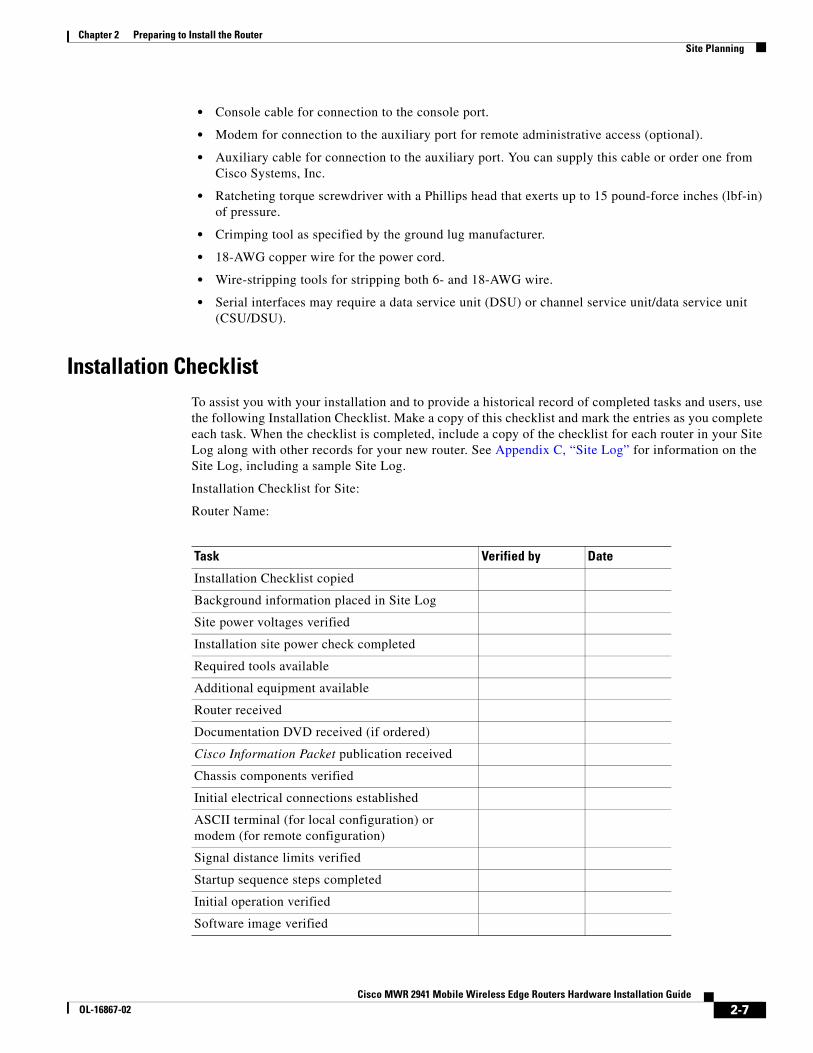
Installation ChecklistTo assist you with your installation and to provide a historical record of completed tasks and users, use the following Installation Checklist. Make a copy of this checklist and mark the entries as you complete each task. When the checklist is completed, include a copy of the checklist for each router in your Site Log along with other records for your new router. See Appendix C, “Site Log” for information on the Site Log, including a sample Site Log.
Installation Checklist for Site:
Router Name:
Task Verified by Date
Installation Checklist copied
Background information placed in Site Log
Site power voltages verified
Installation site power check completed
Required tools available
Additional equipment available
Router received
Documentation DVD received (if ordered)
Cisco Information Packet publication received
Chassis components verified
Initial electrical connections established
ASCII terminal (for local configuration) or modem (for remote configuration)
Signal distance limits verified
Startup sequence steps completed
Initial operation verified
Software image verified
2-7Cisco MWR 2941 Mobile Wireless Edge Routers Hardware Installation Guide
OL-16867-02
Chapter 2 Preparing to Install the RouterConsole/Auxiliary Port Considerations
Creating a Site LogThe Site Log provides a record of all actions related to installing and maintaining the router. Keep it in an accessible place near the chassis so that anyone who performs tasks has access to it.
Create the Site Log prior to installation. (See Appendix C, “Site Log” for more detailed information on the Site Log as well as a sample Site Log that can be used to make copies.)
Console/Auxiliary Port ConsiderationsThe Cisco MWR 2941 router provides a single console/auxiliary port (labeled CON/AUX). A single RJ-45 cable is used for either a console or auxiliary connection.
This section describes important cabling information to consider before connecting a console terminal—either an ASCII terminal or a PC running terminal emulation software—or a modem to the console/auxiliary port. The console/auxiliary port provides access to the router either locally (using a console terminal), or remotely (using a modem).
The main difference between a console connection and an auxiliary connection is that the auxiliary connection supports hardware flow control and the console connection does not. Flow control paces the transmission of data between a sending device and a receiving device. Flow control ensures that the receiving device can process all the data sent to it before the sending device sends more data. When the buffers on the receiving device are full, a message is sent to the sending device to suspend transmission until the data in the buffers has been processed. Because the auxiliary connection supports flow control, it is suited for use with the high-speed transmissions of a modem. Console connections transmit at slower speeds than modems; therefore, the console connection is suited for use with console terminals.
Note Console and rollover cables are not included with the Cisco MWR 2941 router. You can order the console cable from Cisco Systems, Inc. (part number ACS-1900ASYN=). You must supply your own rollover cable.
To change the console port into an auxiliary port, use the modem enable [autodetect] command in line configuration mode. To return the auxiliary port to a console port, use the no form of this command (no modem enable).
This command is not configured by default and is applicable only on the console line. The console port must be changed to act as a virtual auxiliary port using the modem enable [autodetect] command before the dial backup and remote management capabilities can be enabled.
Use the show line autodetect EXEC command to determine when a modem or a console has been detected. The command displays messages to indicate the type or state of connection on the console line.
Console Port ConnectionsThe router provides an EIA/TIA-232 asynchronous serial console port (RJ-45). Depending on the cable and the adapter used, this port appears as a data terminal equipment (DTE) or data communications equipment (DCE) device at the end of the cable.
To connect an ASCII terminal to the console/auxiliary port, use the RJ-45 rollover cable with the female RJ-45-to-DB-25 adapter (labeled TERMINAL). To connect a PC running terminal emulation software to the console/auxiliary port, use the RJ-45 rollover cable with the female RJ-45-to-DB-9 adapter
2-8Cisco MWR 2941 Mobile Wireless Edge Routers Hardware Installation Guide
OL-16867-02
Chapter 2 Preparing to Install the RouterConsole/Auxiliary Port Considerations
(labeled TERMINAL). The default parameters for the port are 9600 baud, 8 data bits, no parity, and 2 stop bits. As a console port, hardware flow control is not supported. For instructions on installing a console terminal, see the “Connecting the Console/Auxiliary Port” section on page 3-10.
For cable and port pinouts, see the online document Cisco Modular Access Router Cable Specifications. This document is provided on the documentation DVD that accompanied your router (if ordered), and is also available online at Cisco.com.
Auxiliary Port ConnectionsThe router includes an EIA/TIA-232 asynchronous serial auxiliary port (RJ-45) that supports flow control. Depending on the cable and the adapter used, this port appears as either a DTE or DCE device at the end of the cable.
To connect a modem to the console/auxiliary port, use an RJ-45 rollover cable with the male RJ-45-to-DB-25 adapter (labeled MODEM). For instructions on connecting devices to the console/auxiliary port, see the “Connecting the Console/Auxiliary Port” section on page 3-10.
For cable and port pinouts, see the online document Cisco Modular Access Router Cable Specifications. This document is provided on the documentation DVD that accompanied your router (if ordered), and is also available online at Cisco.com.
2-9Cisco MWR 2941 Mobile Wireless Edge Routers Hardware Installation Guide
OL-16867-02

Chapter 2 Preparing to Install the RouterConsole/Auxiliary Port Considerations
2-10Cisco MWR 2941 Mobile Wireless Edge Routers Hardware Installation Guide
OL-16867-02
Cisco MWR 2941 Mobile WOL-16867-02
C H A P T E R 3
Installing the Cisco MWR 2941 RouterThis chapter describes how to install your Cisco MWR 2941 router and how to connect it to networks and external devices. This chapter contains the following sections:
• Interface Cards, page 3-1
• Mounting the Cisco MWR 2941 Router, page 3-2
• Connecting the Chassis Ground and Power, page 3-6
• Connecting Cables, page 3-10
• Powering On the Router, page 3-14
Warning Only trained and qualified personnel should be allowed to install, replace, or service this equipment. Statement 1030
Warning This unit is intended for installation in restricted access areas. A restricted access area can be accessed only through the use of a special tool, lock and key, or other means of security. Statement 1017
Interface CardsThe HWIC interface cards are a configurable option. If ordered, they are shipped already installed. If you need to remove or install the card, refer to the applicable documents online.
Note If the HWIC interface card must be removed or installed, we recommend that you perform the installation or removal before you install the chassis.
If the HWIC interface cards are already installed, proceed to the next section “Mounting the Cisco MWR 2941 Router.”
3-1ireless Edge Routers Hardware Installation Guide
Chapter 3 Installing the Cisco MWR 2941 RouterMounting the Cisco MWR 2941 Router
Mounting the Cisco MWR 2941 RouterEach Cisco MWR 2941 router includes rack-mounting brackets. The Cisco MWR 2941-DC includes factory-installed mounting brackets, while the Cisco MWR 2941-DC-A includes the mounting brackets in the accessory kit.
Using the rack-mounting brackets, you can front-mount or center-mount the Cisco MWR 2941 router in a 19-inch (48.3-cm) equipment rack that conforms to the EIA-310-D specification (the inside width of the rack should be 17.72 to 17.80 inches [45 to 45.21 cm]).
Using the two rack-mounting brackets for recessed mounting (part number 700-24513-01), you can recess Cisco MWR 2941 router in the equipment rack. This arrangement provides extra space in front of the router for the cables and allows you to close the doors of racks equipped with front-close doors.
If you need to attach or replace the rack-mounting brackets, see the “Attaching the Rack-Mounting Brackets” section on page 3-3.
The rack-mounting brackets are slotted to allow the router to be mounted in racks with EIA 1.25-inch (3.81-cm) or WECO 1.0-inch (2.54-cm) hole spacing. When installed in the rack, the Cisco MWR 2941 router requires one EIA 1.75-inch (4.4-cm) vertical mounting space (or 1 rack unit [RU]) for mounting (see the “Mounting the Cisco MWR 2941 Router in a Rack” section on page 3-4).
Caution Allow clearance in the front and rear of the Cisco MWR 2941 router for cooling air to be drawn in through the front and circulated through the chassis and out the four fan exhaust ports mounted on the rear of the chassis.
Rack-Mounting Configuration GuidelinesUse the following information to help you plan your equipment rack configuration:
• When mounting the router to an equipment rack, ensure that the rack is bolted to the floor.
• Because you may install more than one router into the rack, ensure that the weight of all of the routers installed does not make the rack unstable.
Caution Some equipment racks are also secured to ceiling brackets, if necessary, due to the weight of the equipment in the rack. Make sure that the rack you are using to install the routers is secured to the building structure.
• As mentioned in the “Air Flow Guidelines” section on page 2-4, maintain a 6-inch (15.2-cm) clearance at the front and rear of the router to ensure adequate air intake and exhaust.
• Avoid installing the routers in an overly congested rack. Air flowing to or from other routers in the rack might interfere with the normal flow of cooling air through the routers, increasing the potential for overtemperature conditions within the routers.
• Allow at least 19 inches (48.7 cm) of clearance at the front and rear of the rack for router maintenance.
• Follow your local practices for cable management. Ensure that cables to and from the routers do not impede access to perform equipment maintenance or upgrades.
3-2Cisco MWR 2941 Mobile Wireless Edge Routers Hardware Installation Guide
OL-16867-02
Chapter 3 Installing the Cisco MWR 2941 RouterMounting the Cisco MWR 2941 Router
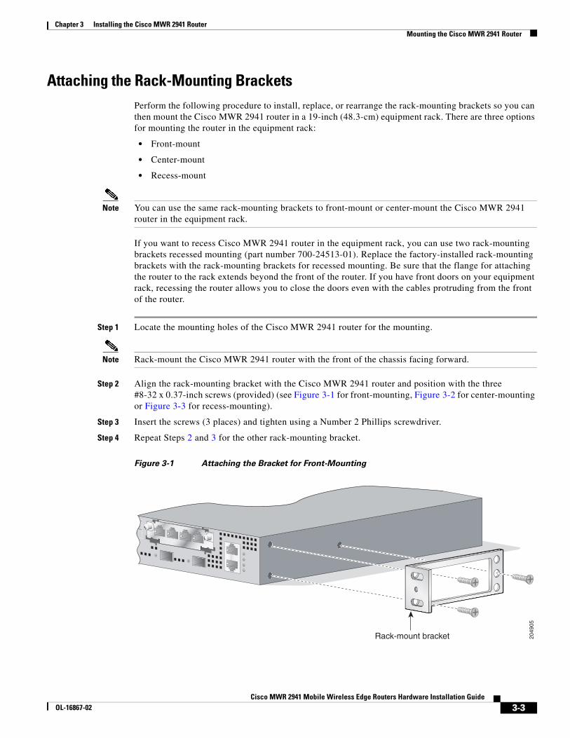
Attaching the Rack-Mounting BracketsPerform the following procedure to install, replace, or rearrange the rack-mounting brackets so you can then mount the Cisco MWR 2941 router in a 19-inch (48.3-cm) equipment rack. There are three options for mounting the router in the equipment rack:
• Front-mount
• Center-mount
• Recess-mount
Note You can use the same rack-mounting brackets to front-mount or center-mount the Cisco MWR 2941 router in the equipment rack.
If you want to recess Cisco MWR 2941 router in the equipment rack, you can use two rack-mounting brackets recessed mounting (part number 700-24513-01). Replace the factory-installed rack-mounting brackets with the rack-mounting brackets for recessed mounting. Be sure that the flange for attaching the router to the rack extends beyond the front of the router. If you have front doors on your equipment rack, recessing the router allows you to close the doors even with the cables protruding from the front of the router.
Step 1 Locate the mounting holes of the Cisco MWR 2941 router for the mounting.
Note Rack-mount the Cisco MWR 2941 router with the front of the chassis facing forward.
Step 2 Align the rack-mounting bracket with the Cisco MWR 2941 router and position with the three #8-32 x 0.37-inch screws (provided) (see Figure 3-1 for front-mounting, Figure 3-2 for center-mounting or Figure 3-3 for recess-mounting).
Step 3 Insert the screws (3 places) and tighten using a Number 2 Phillips screwdriver.
Step 4 Repeat Steps 2 and 3 for the other rack-mounting bracket.
Figure 3-1 Attaching the Bracket for Front-Mounting
2049
05
Rack-mount bracket
3-3Cisco MWR 2941 Mobile Wireless Edge Routers Hardware Installation Guide
OL-16867-02
Chapter 3 Installing the Cisco MWR 2941 RouterMounting the Cisco MWR 2941 Router
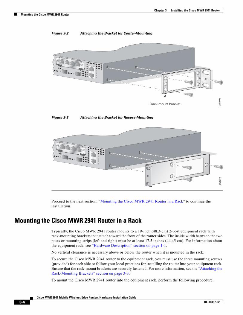
Figure 3-2 Attaching the Bracket for Center-Mounting
Figure 3-3 Attaching the Bracket for Recess-Mounting
Proceed to the next section, “Mounting the Cisco MWR 2941 Router in a Rack” to continue the installation.
Mounting the Cisco MWR 2941 Router in a RackTypically, the Cisco MWR 2941 router mounts to a 19-inch (48.3-cm) 2-post equipment rack with rack-mounting brackets that attach toward the front of the router sides. The inside width between the two posts or mounting strips (left and right) must be at least 17.5 inches (44.45 cm). For information about the equipment rack, see “Hardware Description” section on page 1-1.
No vertical clearance is necessary above or below the router when it is mounted in the rack.
To secure the Cisco MWR 2941 router to the equipment rack, you must use the three mounting screws (provided) for each side or follow your local practices for installing the router into your equipment rack. Ensure that the rack-mount brackets are securely fastened. For more information, see the “Attaching the Rack-Mounting Brackets” section on page 3-3.
To mount the Cisco MWR 2941 router into the equipment rack, perform the following procedure.
2049
06
Rack-mount bracket
2504
76
3-4Cisco MWR 2941 Mobile Wireless Edge Routers Hardware Installation Guide
OL-16867-02
Chapter 3 Installing the Cisco MWR 2941 RouterMounting the Cisco MWR 2941 Router
Caution To prevent injury, review the “Safety Guidelines” section on page 2-1 and the “Rack-Mounting Configuration Guidelines” section on page 3-2 before installing the Cisco MWR 2941 router in the equipment rack.
Step 1 Locate the equipment rack position where you plan to install the Cisco MWR 2941 router.
Step 2 Verify that there are no obstructions and ensure that the equipment rack is stabilized.
Step 3 Position the Cisco MWR 2941 router in the equipment rack lining up the bracket holes on the router with the holes on the rack and secure with four #12-24 x 0.37-inch mounting screws (two on each side).
Note The vertical spacing for EIA equipment racks is 1.75 inches (4.44 cm), with mounting holes spaced 1.5 inches (3.81 cm) apart. Vertical spacing for WECO racks is 2.0 inches (5.08 cm), with mounting holes spaced 1.0 inch (2.54 cm) apart.
Step 4 Tighten the screws using a 1/4-inch flat-blade screwdriver (each side).
If your router is front-mounted, proceed to the section “Attaching the Cable Guides.” If your router is center-mounted or recess-mounted, proceed to section, “Connecting the Chassis Ground and Power.”
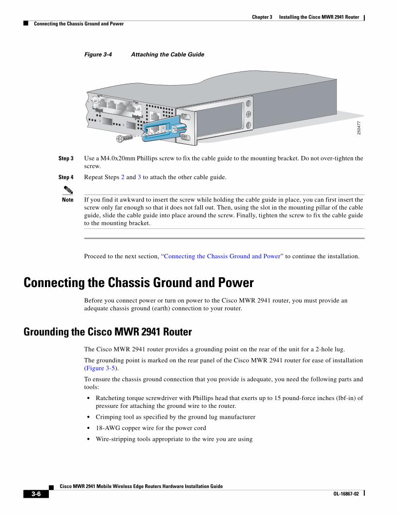
Attaching the Cable GuidesPerform the following procedure to attach the two cable guides to the front of the mounting brackets. This procedure is optional.
Note The cable guides are practical only if your router is front-mounted. Do not attach the cable guides if your router is center-mounted or recess-mounted.
Use the cable guides to dress the cables that you will attach to the front of the Cisco MWR 2941 router. The cable guides allow you to gather the cables and direct them to the left and right sides of the router. This helps to keep the cables from obscuring the fronts of lower routers in the same rack.
Step 1 In the accessory kit, locate the two cable guides (part number 700-01663-01) and two M4.0x20mm Phillips screws used to attach the cable guides (part number 48-0654-01).
Step 2 Position the cable guide over the threaded hole in the front flange of either the left or right mounting bracket. The threaded hole is located midway between the two slotted holes used to mount the unit to the rack (Figure 3-4).
3-5Cisco MWR 2941 Mobile Wireless Edge Routers Hardware Installation Guide
OL-16867-02
Chapter 3 Installing the Cisco MWR 2941 RouterConnecting the Chassis Ground and Power
Figure 3-4 Attaching the Cable Guide
Step 3 Use a M4.0x20mm Phillips screw to fix the cable guide to the mounting bracket. Do not over-tighten the screw.
Step 4 Repeat Steps 2 and 3 to attach the other cable guide.
Note If you find it awkward to insert the screw while holding the cable guide in place, you can first insert the screw only far enough so that it does not fall out. Then, using the slot in the mounting pillar of the cable guide, slide the cable guide into place around the screw. Finally, tighten the screw to fix the cable guide to the mounting bracket.
Proceed to the next section, “Connecting the Chassis Ground and Power” to continue the installation.
Connecting the Chassis Ground and PowerBefore you connect power or turn on power to the Cisco MWR 2941 router, you must provide an adequate chassis ground (earth) connection to your router.
Grounding the Cisco MWR 2941 Router The Cisco MWR 2941 router provides a grounding point on the rear of the unit for a 2-hole lug.
The grounding point is marked on the rear panel of the Cisco MWR 2941 router for ease of installation (Figure 3-5).
To ensure the chassis ground connection that you provide is adequate, you need the following parts and tools:
• Ratcheting torque screwdriver with Phillips head that exerts up to 15 pound-force inches (lbf-in) of pressure for attaching the ground wire to the router.
• Crimping tool as specified by the ground lug manufacturer
• 18-AWG copper wire for the power cord
• Wire-stripping tools appropriate to the wire you are using
2504
77
3-6Cisco MWR 2941 Mobile Wireless Edge Routers Hardware Installation Guide
OL-16867-02
Chapter 3 Installing the Cisco MWR 2941 RouterConnecting the Chassis Ground and Power
Caution Before making connections to the Cisco MWR 2941 router, ensure that you disconnect the power at the circuit breaker. Otherwise severe injury or damage to the router may result.
Warning This equipment must be grounded. Never defeat the ground conductor or operate the equipment in the absence of a suitably installed ground conductor. Contact the appropriate electrical inspection authority or an electrician if you are uncertain that suitable grounding is available. Statement 1024
Warning Use copper conductors only. Statement 1025
Warning When installing the unit, the ground connection must always be made first and disconnected last. Statement 42
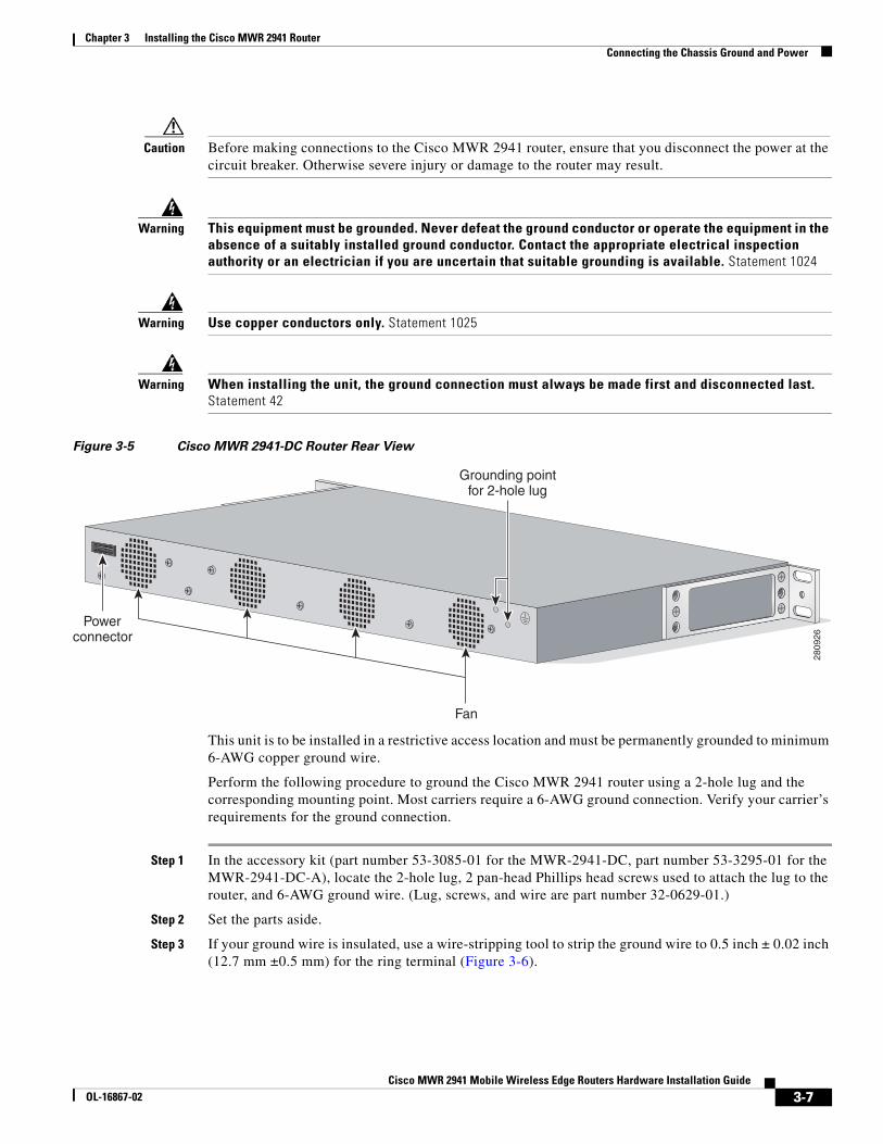
Figure 3-5 Cisco MWR 2941-DC Router Rear View
This unit is to be installed in a restrictive access location and must be permanently grounded to minimum 6-AWG copper ground wire.
Perform the following procedure to ground the Cisco MWR 2941 router using a 2-hole lug and the corresponding mounting point. Most carriers require a 6-AWG ground connection. Verify your carrier’s requirements for the ground connection.
Step 1 In the accessory kit (part number 53-3085-01 for the MWR-2941-DC, part number 53-3295-01 for the MWR-2941-DC-A), locate the 2-hole lug, 2 pan-head Phillips head screws used to attach the lug to the router, and 6-AWG ground wire. (Lug, screws, and wire are part number 32-0629-01.)
Step 2 Set the parts aside.
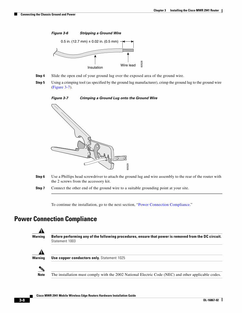
Step 3 If your ground wire is insulated, use a wire-stripping tool to strip the ground wire to 0.5 inch ± 0.02 inch (12.7 mm ±0.5 mm) for the ring terminal (Figure 3-6).
Power connector
Fan
Grounding point for 2-hole lug
2809
26
3-7Cisco MWR 2941 Mobile Wireless Edge Routers Hardware Installation Guide
OL-16867-02
Chapter 3 Installing the Cisco MWR 2941 RouterConnecting the Chassis Ground and Power
Figure 3-6 Stripping a Ground Wire
Step 4 Slide the open end of your ground lug over the exposed area of the ground wire.
Step 5 Using a crimping tool (as specified by the ground lug manufacturer), crimp the ground lug to the ground wire (Figure 3-7).
Figure 3-7 Crimping a Ground Lug onto the Ground Wire
Step 6 Use a Phillips head screwdriver to attach the ground lug and wire assembly to the rear of the router with the 2 screws from the accessory kit.
Step 7 Connect the other end of the ground wire to a suitable grounding point at your site.
To continue the installation, go to the next section, “Power Connection Compliance.”
Power Connection Compliance
Warning Before performing any of the following procedures, ensure that power is removed from the DC circuit. Statement 1003
Warning Use copper conductors only. Statement 1025
Note The installation must comply with the 2002 National Electric Code (NEC) and other applicable codes.
InsulationWire lead
0.5 in. (12.7 mm) ± 0.02 in. (0.5 mm)
6052
8
6052
9
3-8Cisco MWR 2941 Mobile Wireless Edge Routers Hardware Installation Guide
OL-16867-02
Chapter 3 Installing the Cisco MWR 2941 RouterConnecting the Chassis Ground and Power
Wiring the DC-Input Power Source
Warning This product relies on the building’s installation for short-circuit (overcurrent) protection. Ensure that the protective device is rated not greater than 10 A minimum, 60 VDC. Statement 1005
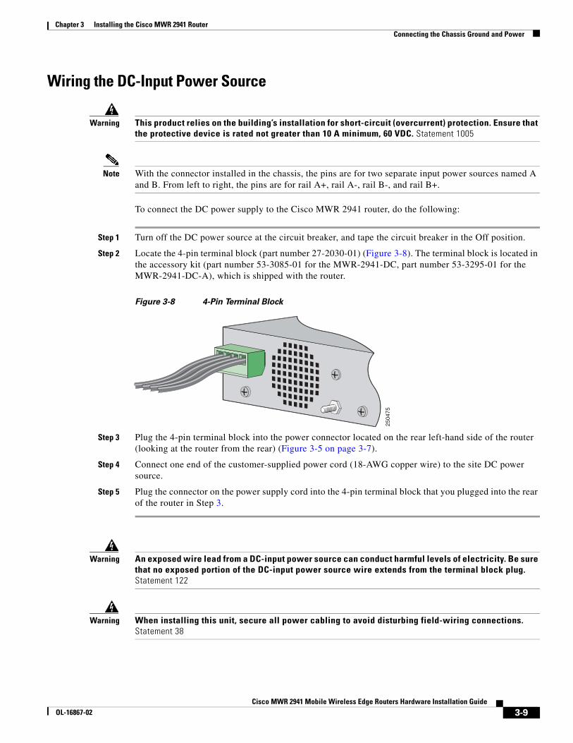
Note With the connector installed in the chassis, the pins are for two separate input power sources named A and B. From left to right, the pins are for rail A+, rail A-, rail B-, and rail B+.
To connect the DC power supply to the Cisco MWR 2941 router, do the following:
Step 1 Turn off the DC power source at the circuit breaker, and tape the circuit breaker in the Off position.
Step 2 Locate the 4-pin terminal block (part number 27-2030-01) (Figure 3-8). The terminal block is located in the accessory kit (part number 53-3085-01 for the MWR-2941-DC, part number 53-3295-01 for the MWR-2941-DC-A), which is shipped with the router.
Figure 3-8 4-Pin Terminal Block
Step 3 Plug the 4-pin terminal block into the power connector located on the rear left-hand side of the router (looking at the router from the rear) (Figure 3-5 on page 3-7).
Step 4 Connect one end of the customer-supplied power cord (18-AWG copper wire) to the site DC power source.
Step 5 Plug the connector on the power supply cord into the 4-pin terminal block that you plugged into the rear of the router in Step 3.
Warning An exposed wire lead from a DC-input power source can conduct harmful levels of electricity. Be sure that no exposed portion of the DC-input power source wire extends from the terminal block plug. Statement 122
Warning When installing this unit, secure all power cabling to avoid disturbing field-wiring connections. Statement 38
2504
75
3-9Cisco MWR 2941 Mobile Wireless Edge Routers Hardware Installation Guide
OL-16867-02
Chapter 3 Installing the Cisco MWR 2941 RouterConnecting Cables
Caution DO NOT power on the unit yet.
To continue the installation, proceed to the next section, “Connecting Cables.”
Connecting CablesThis section describes how to connect your Cisco MWR 2941 router to external devices and networks. It includes the following sections:
• Connecting the Console/Auxiliary Port, page 3-10
• Connecting the Network Cables, page 3-11
• Connecting GPS Cables, page 3-13
• Dressing Router Cables, page 3-14
Connecting the Console/Auxiliary Port
Warning Do not work on the system or connect or disconnect cables during periods of lightning activity. Statement 1001
Your Cisco MWR 2941 router has a single console/auxiliary port that can function in either DTE or DCE mode:
• DTE-mode console (terminal) port for connecting a console terminal
• DCE-mode auxiliary (modem) port for connecting a modem or other DCE device (such as, a CSU/DSU or other router) to your router
Note Both the console and auxiliary port functions are asynchronous serial ports; any devices connected to the console/auxiliary port must be cabled for asynchronous transmission. (Asynchronous is the most common type of serial device; for example, most modems are asynchronous devices.)
The Cisco MWR 2941 router uses RJ-45 ports for both the auxiliary port and console port function.
Cisco provides the following cables and adapters for connecting your Cisco MWR 2941 router to a console terminal, PC, or modem:
• One console adapter cable (RJ-45-to-DB-9, blue)
• One modem adapter cable (RJ-45-to-DB-25, black)
Types of RJ-45 Cables
Cisco products use the following three types of RJ-45 cables:
• Straight-through
• Crossover
• Rolled (or Rollover)
3-10Cisco MWR 2941 Mobile Wireless Edge Routers Hardware Installation Guide
OL-16867-02
Chapter 3 Installing the Cisco MWR 2941 RouterConnecting Cables
Your Cisco MWR 2941 router ships with and uses the rollover cable. For instructions on how to identify a rollover cable, see Identifying a Rollover Cable, page B-5.
Console Port
To connect a terminal or a PC running terminal emulation software to the console/auxiliary port on the router:
Step 1 Connect the terminal using an RJ-45 rollover cable and an RJ-45-to-DB-25 or RJ-45-to-DB-9 adapter (labeled TERMINAL) to the console/auxiliary port. For cable pinouts, see the “Console Port Signals and Pinouts” section on page B-3.
Note The RJ-45-to-DB-25 adapter (Cisco part number 29-0810-01) can be purchased from Cisco Systems.
Step 2 Configure your terminal or terminal emulation software for 9600 baud, 8 data bits, no parity, and 2 stop bits.
Note Because hardware flow control is not possible on the console port, we recommend changing the console/auxiliary port from console port to auxiliary port before connecting modems to the console/auxiliary port.
Auxiliary Port
To connect a modem to the console/auxiliary port on the router, follow these steps:
Step 1 If necessary, change the console port to an auxiliary port using the modem enable [autodetect] command.
Step 2 Connect a modem to the console/auxiliary port using an RJ-45 rollover cable with an RJ-45-to-DB-25 adapter. The provided adapter is labeled MODEM. For cable pinouts, see the “Auxiliary Port Signals and Pinouts” section on page B-4 of this guide or the online publication Cisco Modular Access Router Cable Specifications available on the documentation DVD and online at Cisco.com.
Step 3 Make sure that your modem and the router auxiliary port are configured for the same transmission speed (a speed of up to 115200 bps is supported) and hardware flow control with Data Carrier Detect (DCD) and Data Terminal Ready (DTR) operation.
Connecting the Network CablesThis section describes how to connect the following router interfaces:
• Connecting Fixed Gigabit Ethernet Interface Cables, page 3-12
• Connecting T1 and E1 Interface Cables, page 3-12
3-11Cisco MWR 2941 Mobile Wireless Edge Routers Hardware Installation Guide
OL-16867-02
Chapter 3 Installing the Cisco MWR 2941 RouterConnecting Cables
• Connecting Cables for Switchport Stacking, page 3-12
• Connecting Cables to the BITS Interface, page 3-13
Connecting Fixed Gigabit Ethernet Interface Cables
The RJ-45 port supports standard straight-through and crossover Category 5 unshielded twisted-pair (UTP) cables. Cisco Systems does not supply Category 5 UTP cables; these cables are available commercially.
Follow these steps to connect the cable to the router Gigabit Ethernet port:
Step 1 Confirm that the router is powered off.
Step 2 Connect one end of the cable to the GE port on the router.
Step 3 Connect the other end to the BTS patch or demarcation panel at your site.
For more information about Gigabit Ethernet connectors including pinouts, see Gigabit Ethernet Connector Pinouts, page B-1.
Connecting T1 and E1 Interface Cables
Follow these steps to connect the cable to a router T1/E1 port:
Note You must close the relays on the card using the standalone subcommand. For more information, see the Cisco MWR 2941 Mobile Wireless Edge Router Software Configuration Guide.
Step 1 Confirm that the router is powered off.
Step 2 Connect one end of the cable to the T1 or E1 (RJ-48C) port. Use a straight-through, shielded RJ-48C-to-RJ-48C cable.
Step 3 Connect the other end to the BTS patch or demarcation panel at your site.
Step 4 Turn on power to the router (see “Powering On the Router” section on page 3-14 for more details).
For more information about T1/E1 connectors including pinouts, see T1/E1 Port Pinouts, page B-2.
Connecting Cables for Switchport Stacking
The HWIC-9ESW card supports stacking, which allows two switch modules to behave as a single switch. Follow these steps to connect cables for switchport stacking.
Step 1 Connect a crossover cable to port 8 of the HWIC-9ESW card.
Step 2 Connect the other end of the crossover cable to the GigabitEthernet switch port that you want to use as a stacking partner.
3-12Cisco MWR 2941 Mobile Wireless Edge Routers Hardware Installation Guide
OL-16867-02
Chapter 3 Installing the Cisco MWR 2941 RouterConnecting Cables
For information about how to install the HWIC-D-9ESW Card, see 10/100BASE-T Ethernet Switch High-Speed WAN Interface Cards. For information about how to configure the HWIC-9ESW card, see the Cisco MWR 2941 Mobile Wireless Edge Router Software Configuration Guide.
Connecting Cables to the BITS Interface
Follow these steps to connect the cable to the router BITS port:
Step 1 Confirm that the router is powered off.
Step 2 Connect one end of the cable to the BITS port using a straight-through, shielded RJ-48C-to-RJ-48C cable.
Step 3 Connect the other end to the BTS patch or demarcation panel at your site.
Step 4 Turn on power to the router (see “Powering On the Router” section on page 3-14 for more details).
For more information about T1/E1 connectors including pinouts, see BITS Pinouts, page B-6.
Connecting GPS CablesThe following sections describe how to connect cables from the Cisco MWR 2941 to a GPS unit for input or output timing or frequency.
• Connecting Cables to the 10Mhz or 1PPS Interface
• Connecting Cables to the BITS/ToD Interface
Note This section does not apply to the Cisco MWR 2941-DC as it does not include the 10Mhz and 1PPS timing ports.
Connecting Cables to the 10Mhz or 1PPS Interface
Step 1 Connect one end of a mini-coax cable to the GPS unit.
Step 2 Connect the other end of the mini-coax cable to the 10Mhz or 1PPS port on the Cisco MWR 2941-DC-A.
For instructions on how to configure clocking, see the Cisco MWR 2941 Mobile Wireless Edge Router Software Configuration Guide.
Connect the GPS unit to the 10Mhz, 1PPS, or BITS/ToD port on the Cisco MWR 2941-DC-A.
Connecting Cables to the BITS/ToD Interface
Follow these steps to connect cables to the BITS/ToD interface for GPS timing.
Step 1 Connect one end of a straight-through Ethernet cable to the GPS unit.
Step 2 Connect the other end of the cable to the BITS/ToD port on the Cisco MWR 2941-DC-A.
3-13Cisco MWR 2941 Mobile Wireless Edge Routers Hardware Installation Guide
OL-16867-02
Chapter 3 Installing the Cisco MWR 2941 RouterPowering On the Router
For instructions on how to configure clocking, see the Cisco MWR 2941 Mobile Wireless Edge Router Software Configuration Guide.
Note For more information about GPS port pinouts, see GPS Port Pinouts, page B-6.
Dressing Router CablesEnsure all Cisco router cables are properly dressed so as not to interfere with each other or other pieces of equipment. Use local practices to ensure that the cables attached to your router are properly dressed.
Note If your Cisco MWR 2941 router is front-mounted, you can use the cable guide (found in the accessory kit) to dress the cables.
To continue the installation, proceed to the next section, “Powering On the Router.”
Powering On the Router
Warning Do not touch the power supply when the power cord is connected. For systems with a power switch, line voltages are present within the power supply even when the power switch is off and the power cord is connected. For systems without a power switch, line voltages are present within the power supply when the power cord is connected. Statement 4
Warning This equipment is intended to be grounded. Ensure that the host is connected to earth ground during normal use. Statement 39
Checklist for Power UpYou are ready to power on the Cisco MWR 2941 router if the following steps are complete:
• Router is securely mounted.
• Power, network, and interface cables are properly connected.
Interpreting Front-Panel LEDsThe Cisco MWR 2941 router provides a number of LEDs on the front panel to monitor conditions and to aid in troubleshooting problems. For a description of the LEDs, see the “Reading the LEDs” section on page A-5.
3-14Cisco MWR 2941 Mobile Wireless Edge Routers Hardware Installation Guide
OL-16867-02
Chapter 3 Installing the Cisco MWR 2941 RouterPowering On the Router
Power-On ProcedureTo power on the Cisco MWR 2941 router and verify its initialization and self-test, follow this procedure. When the procedure is finished, the Cisco MWR 2941 router is ready to configure.
Step 1 Remove the tape from the circuit breaker switch handle.
Step 2 Reinstate power by moving the handle of the circuit breaker to the On position.
The LED (labeled POWER) on the front panel should go on and the fans operate.
Depending on your installation, other front-panel LEDs should also come on.
Note If you encounter problems when you power on the router, see Appendix A, “Troubleshooting.”
Formatting Procedures for Flash Memory CardsFor the Cisco MWR 2941 router, we recommend that you format/erase the flash memory card to initialize them with a Class C flash file system. This ensures proper formatting and enables the ROM monitor to recognize and boot the flash.
The Class C flash file system is similar to the standard DOS file system; however, a flash memory card formatted with the standard DOS file system does not support booting from the ROM monitor.
Formatting Flash Memory Card as a DOS File System
To format a built-in flash memory card, or to remove the files from a flash memory card, enter the format flash: command.
The following example shows output for formatting a flash memory card formatted with a Class C flash file system:
Router# format flash:
Format operation may take a while. Continue? [confirm]Format operation will destroy all data in "flash:". Continue? [confirm]Enter volume ID (up to 64 chars)[default flash]:Current Low End File System flash card in flash will be formatted into DOSFile System flash card! Continue? [confirm]Format:Drive communication & 1st Sector Write OK...Writing Monlib sectors ...................................................................Monlib write complete..Format:All system sectors written. OK... Format:Total sectors in formatted partition:250592Format:Total bytes in formatted partition:128303104Format:Operation completed successfully. Format of flash complete
3-15Cisco MWR 2941 Mobile Wireless Edge Routers Hardware Installation Guide
OL-16867-02
Chapter 3 Installing the Cisco MWR 2941 RouterPowering On the Router
File and Directory ProceduresThe following sections describe file and directory procedures for flash memory cards formatted with a Class C flash file system.
Copying Files
To copy the files to another location, use the copy flash: source-filename {flash: | tfp: | lex: | null: | nvram: | pram: | rcp: | system: | tftp: | xmodem: | ymodem: | running-config | startup-config} destination-filename command.
The following example shows output for copying a Cisco IOS file from an external flash memory card to a TFTP server:
Router# copy flash:mwr2941-ipran-mz.tmp tftp:
Destination filename [mwr2941-ipran-mz.tmp]?CCCCCCCCCCCCCCCCCCCCCCCCCCCCCCCCCCCCCCCCCCCCCCCCCCCCCCCCCCCCCCCCCCCCCCCCCCCCCCCCCCCCCCCCCCCCCCCCCCCCCCCCCCCCCCCCCCCCCCCCCCCCCCCCCCCCCCCCCCCCCCCCCCCCCCCCCCCCCCCCCCCCCCCCCCCCCCCCCCCCCCCCCCCCCCCCCCCCCCCCCCCCCCCCCCCCCCCCCCCCCCCCCCCCCCCCCCCCCCCCCCCCCCCCCCCCCCCCCCCCCCCCCCCCCCCCCCCCCCCCCCCCCCCCCCCCCCCCCCCCCCCCCCCCCCCCCCCCCCCCCCCCCCCCCCCCCCCCCCCCCCCCCCCCCCCCCCCCCCCCCCCCCCCCCCCCCCCCCCCCCCCCCCCCCCCCCCCCCCCCCCCCCCCCCCCCCCCCCCCCCCCCCCCCCCCCCCCCCCCCCCCCCCCCCCCCCCCCCCCCCCCCCCCCCCCCCCCCCCCCCCCCCCCCCCCCCCCCCCCCCCCCCCCCCCCCCCCCCCCCCCCCCCCCCCCCCCCCCCCCCCCCCCCCCCCCCCCCCCCCCCCCCCCCCCCCCCCCCCCCCCCCCCCCCCCCCCCCCCCCCCCCCCCCCCCCCCCCCCCCCCCCCCCCCCCCCCCCCCCCCCCCCCCCCCCCCCCCCCCCCCCCCCCCCCCCCCCCCCCCCCCCCCCCCCCCCCCCCCCCCCCCCCCCCCCCCCCCCCCCCCCCCCCCCCCCCCCCCCCCCCCCCCCCCCCCCCCCCCCCCCCCCCCCCCCCCCCCCCCCCCCCCCCCCCCCCCCCCCCCCCCCCCCCCCCCCCCCCCCCCCCCCCCCCCCCCCCCCCCCCCCCCCCCCCCCCCCCCCCCCCCCCCCCCCCCCCCCCCCCCCCCCCCCCCCCCCCCCCCCCCCCCCCCCCCCCCCCCCCCCCCCCCCCCCCCCCCCCCCCCCCCCCCCCCCCCCCCCCCCCCCCCCCCCCCCCCCCCCCCCCCCCCCCCCCCCCCCCCCCCCCCCCCCCCCCCCCCCCCCCCCCCCCCCCCCCCCCCCCCCCCCCCCCCCCCCCCCCCCCCCCCCCCCCCCCCCCCCCCCCCCCCCCCCCCCCCCCCCCCCCCCCCCCCCCCCCCCCCCCCCCCCCCCCCCCCCCCCCCCCCCCCCCCCCCCCCCCCCCCCCCCCCCCCCCCCCCCCCCCCCCCCCCCCCCCCCCCCCCCCCCCCCCCCCCCCCCCCCCCCCCCCCCCCCCCCCCCCCCCCCCCCCCCCCCCCCCCCCCCCCCCCCCCCCCCCCCCCCCCCCCCCCCCCCCCCCCCCCCCCCCCCCCCCCCCCCCCCCCCCCCCCCCCCCCCCCCCCCCCCCCCCCCCCCCCCCCCCCCCCCCCCCCCCCCCCCCCCCCCCCCCCCCCCCCCCCCCCCCCCCCCCCCCCCCCCCCCCCCCCCCCCCCCCCCCCCCCCCCCCCCCCCCCCCCCCCCCCCCCCCCCCCCCCCCCCCCCCCCCCCCCCCCCCCCCCCCCCCCCCCCCCCCCCCCCCCCCCCCCCCCCCCCCCCCCCCCCCCCCCCCCCCCCCCCCCCCCCCCCCCCCCCCCCCCCCCCCC6458584 bytes copied in 202.940 secs (31973 bytes/sec)
Displaying the Contents of a Flash Card
To display the contents (directories and files) of a flash memory card formatted with a Class C flash file system, use the dir flash: command.
The following example shows output for displaying the contents of a flash memory card with a Class C flash file system:
Router# dir flash:
Directory of flash:/ 3 -rw- 6455048 Mar 01 2001 00:04:06 mwr2941-ipran-mz1579 -rw- 6458584 Mar 01 2001 00:24:38 mwr2941-ipran-mz.new 15912960 bytes total (2998272 bytes free)
Displaying Geometry and Format Information
To display the geometry and format information of a flash memory card formatted with a Class C flash file system, use the show flash: command.
3-16Cisco MWR 2941 Mobile Wireless Edge Routers Hardware Installation Guide
OL-16867-02
Chapter 3 Installing the Cisco MWR 2941 RouterPowering On the Router
The following example shows output for displaying the geometry and format information of a flash memory card formatted with a Class C flash file system:
Router# show flash:
******** ATA Flash Card Geometry/Format Info ******** ATA CARD GEOMETRY Number of Heads: 2 Number of Cylinders 490 Sectors per Cylinder 32 Sector Size 512Total Sectors 31360 ATA CARD FORMAT Number of FAT Sectors 12 Sectors Per Cluster 8 Number of Clusters 3885 Number of Data Sectors 31264 Base Root Sector 152 Base FAT Sector 128 Base Data Sector 184 Please use "dir" command to display the contents of the card.
Deleting Files from a Flash Memory Card
To delete a file from a flash memory card, use the delete flash: filename command.
The following example shows output for deleting a Cisco IOS software file from a flash card:
Router# delete flash:mwr2941-ipran-mz.tmp
Delete filename [mwr2941-ipran-mz.tmp]?Delete flash:mwr2941-ipran-mz.tmp? [confirm]Router# dir flash:Directory of flash:/ No files in directory 128094208 bytes total (128094208 bytes free)
Renaming a File in a Flash Memory Card
To rename a file in a flash memory card, use the rename flash: original-filename flash: new-filename command.
The following example shows output for renaming a Cisco IOS software file in a flash card:
Router# rename flash:mwr2941-ipran-mz.tmp flash:mwr2941-ipran-mz
Destination filename [mwr2941-ipran-mz]?Router# dir flash:
Directory of flash:/ 1580 -rw- 6462268 Mar 06 1993 06:14:02 mwr2941-ipran-mz.2941ata 3 -rw- 6458388 Mar 01 1993 00:01:24 mwr2941-ipran-mz 63930368 bytes total (51007488 bytes free)
3-17Cisco MWR 2941 Mobile Wireless Edge Routers Hardware Installation Guide
OL-16867-02
Chapter 3 Installing the Cisco MWR 2941 RouterPowering On the Router
Displaying File Content
To display the content of a file in a flash memory card, use the more flash: filename command.
The following example shows output from the more flash command on a flash card:
Router# more flash:mwr2941-ipran-mz.tmp
00000000: 7F454C46 01020100 00000000 00000000 .ELF .... .... ....00000010: 00020061 00000001 80008000 00000034 ...a .... .... ...400000020: 00000054 20000001 00340020 00010028 ...T ... .4. ...(00000030: 00050008 00000001 0000011C 80008000 .... .... .... ....00000040: 80008000 00628A44 00650EEC 00000007 .... .b.D .e.l ....00000050: 0000011C 0000001B 00000001 00000006 .... .... .... ....00000060: 80008000 0000011C 00004000 00000000 .... .... ..@. ....00000070: 00000000 00000008 00000000 00000021 .... .... .... ...!00000080: 00000001 00000002 8000C000 0000411C .... .... ..@. ..A.00000090: 00000700 00000000 00000000 00000004 .... .... .... ....000000A0: 00000000 00000029 00000001 00000003 .... ...) .... ....000000B0: 8000C700 0000481C 00000380 00000000 ..G. ..H. .... ....000000C0: 00000000 00000004 00000000 0000002F .... .... .... .../000000D0: 00000001 10000003 8000CA80 00004B9C .... .... ..J. ..K.000000E0: 00000020 00000000 00000000 00000008 ... .... .... ....000000F0: 00000000 0000002F 00000001 10000003 .... .../ .... ....00000100: 8000CAA0 00004BBC 00623FA4 00000000 ..J ..K< .b?$ ....00000110: 00000000 00000008 00000000 3C1C8001 .... .... .... <...00000120: 679C4A80 3C018001 AC3DC70C 3C018001 g.J. <... ,=G. <...00000130: AC3FC710 3C018001 AC24C714 3C018001 ,?G. <... ,$G. <...00000140: AC25C718 3C018001 AC26C71C 3C018001 ,%G. <... ,&G. <...00000150: AC27C720 3C018001 AC30C724 3C018001 ,'G <... ,0G$ <...00000160: AC31C728 3C018001 AC32C72C 3C018001 ,1G( <... ,2G, <...--More-- q
Creating a New Directory
To create a directory in flash memory, use the mkdir flash: directory-name command.
The following example shows output for displaying the contents of a flash card, and then creating a config directory, followed by a test-config subdirectory:
Router# dir flash:
Directory of flash:/ 3 -rw- 6458208 Mar 01 1993 00:04:08 mwr2941-ipran-mz.tmp 128094208 bytes total (121634816 bytes free)Router# mkdir flash:/config
Create directory filename [config]?Created dir flash:/configRouter# mkdir flash:/config/test-config
Create directory filename [/config/test-config]?Created dir flash:/config/test-configRouter# dir flash:
Directory of flash:/ 3 -rw- 6458208 Mar 01 1993 00:04:08 mwr2941-ipran-mz.tmp 1580 drw- 0 Mar 01 1993 23:48:36 config 128094208 bytes total (121626624 bytes free)
3-18Cisco MWR 2941 Mobile Wireless Edge Routers Hardware Installation Guide
OL-16867-02
Chapter 3 Installing the Cisco MWR 2941 RouterPowering On the Router
Router# cd flash:/config
Router# dir flash:
Directory of flash:/config/ 1581 drw- 0 Mar 01 1993 23:50:08 test-config 128094208 bytes total (121626624 bytes free)
Removing a Directory
To remove a directory from flash memory, use the rmdir flash:/directory-name command.
Before removing a directory, remove all files and subdirectories from the directory.
The following example shows output for displaying the contents of a flash card, and then removing the test-config directory:
Router# dir flash:
Directory of flash:/config/ 1581 drw- 0 Mar 01 1993 23:50:08 test-config 128094208 bytes total (121626624 bytes free)Router# rmdir flash:/config/test-config
Remove directory filename [/config/test-config]?Delete flash:/config/test-config? [confirm]Removed dir flash:/config/test-configRouter# dir flash:
Directory of flash:/config/ No files in directory 128094208 bytes total (121630720 bytes free)
Enter a Directory and Determine the Current Directory
To enter a directory in flash memory, use the cd flash:/directory-name command. To determine which directory you are in, use the pwd command.
The following example shows output for the following actions:
• Entering the home directory of a flash memory card in an external slot (flash:/)
• Verifying that you are in the flash:/ directory
Router# cd flash:
Router# pwd
flash:/
3-19Cisco MWR 2941 Mobile Wireless Edge Routers Hardware Installation Guide
OL-16867-02
Chapter 3 Installing the Cisco MWR 2941 RouterPowering On the Router
What to Do After Installing the HardwareAfter you have installed the router hardware, refer to the Cisco MWR 2941 Mobile Wireless Edge Software Configuration Guide for initial software configuration information.
3-20Cisco MWR 2941 Mobile Wireless Edge Routers Hardware Installation Guide
OL-16867-02
Cisco MWR 2941 Mobile WirelesOL-16867-02
A
P P E N D I X A TroubleshootingThe Cisco MWR 2941 router undergoes extensive testing before it leaves the factory. If you encounter problems, use the information in this appendix to help isolate problems or to eliminate the router as the source of the problem.
This appendix contains the following sections:
• Problem Solving, page A-1
• Reading the LEDs, page A-5
If you cannot locate the source of the problem, contact a customer service representative for information on how to proceed. For technical support information, see the Cisco Information Packet publication that shipped with your router. Before you call, have the following information ready:
• Chassis type and serial number
• Maintenance agreement or warranty information
• Type of software and version number
• Date you received the new chassis
• Brief description of the problem
• Brief explanation of the steps you have taken to isolate the problem
Note Ensure you provide the customer service representative with any upgrade or maintenance information that was performed on the Cisco MWR 2941 router after your initial installation (see Appendix C, “Site Log” for Site Log information.)
Problem SolvingTo problem solve, isolate the problem to a specific subsystem by comparing current router activity to expected router activity.
The LEDs on the front panel of the router enable you to determine router performance and operation. For a description of these LEDs, see “Reading the LEDs” section on page A-5.
When problem solving, check the following router subsystems:
• Power and cooling systems—External power source, power cable, router power supply and circuit breaker, and router fans. Also check for inadequate ventilation or air circulation.
• Modules—Checking the LEDs on the modules can help you to identify a failure.
A-1s Edge Routers Hardware Installation Guide
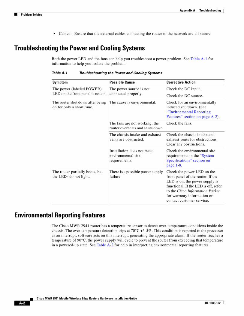
Appendix A TroubleshootingProblem Solving
• Cables—Ensure that the external cables connecting the router to the network are all secure.
Troubleshooting the Power and Cooling SystemsBoth the power LED and the fans can help you troubleshoot a power problem. See Table A-1 for information to help you isolate the problem.
Environmental Reporting FeaturesThe Cisco MWR 2941 router has a temperature sensor to detect over-temperature conditions inside the chassis. The over-temperature detection trips at 70°C +/- 5%. This condition is reported to the processor as an interrupt; software acts on this interrupt, generating the appropriate alarm. If the router reaches a temperature of 90°C, the power supply will cycle to prevent the router from exceeding that temperature in a powered-up state. See Table A-2 for help in interpreting environmental reporting features.
Table A-1 Troubleshooting the Power and Cooling Systems
Symptom Possible Cause Corrective Action
The power (labeled POWER) LED on the front panel is not on.
The power source is not connected properly.
Check the DC input.
Check the DC source.
The router shut down after being on for only a short time.
The cause is environmental. Check for an environmentally induced shutdown. (See “Environmental Reporting Features” section on page A-2).
The fans are not working; the router overheats and shuts down.
Check the fans.
The chassis intake and exhaust vents are obstructed.
Check the chassis intake and exhaust vents for obstructions. Clear any obstructions.
Installation does not meet environmental site requirements.
Check the environmental site requirements in the “System Specifications” section on page 1-8.
The router partially boots, but the LEDs do not light.
There is a possible power supply failure.
Check the power LED on the front panel of the router. If the LED is on, the power supply is functional. If the LED is off, refer to the Cisco Information Packet for warranty information or contact customer service.
A-2Cisco MWR 2941 Mobile Wireless Edge Routers Hardware Installation Guide
OL-16867-02
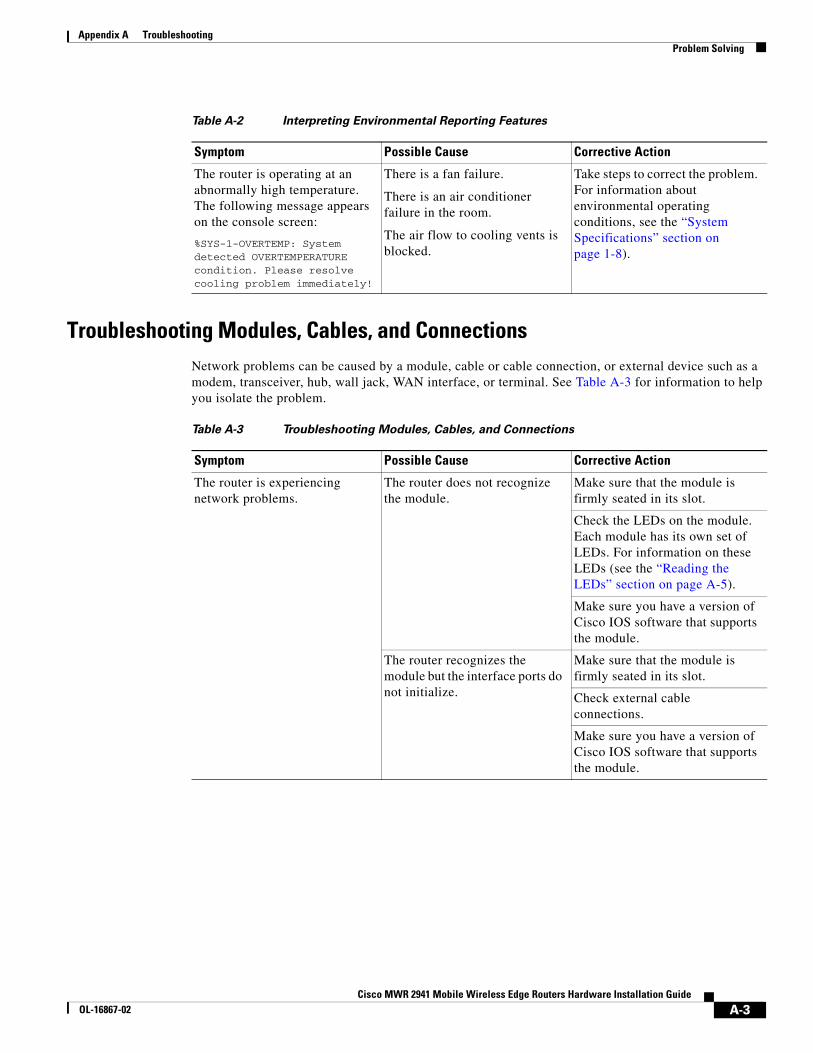
Appendix A TroubleshootingProblem Solving
Troubleshooting Modules, Cables, and ConnectionsNetwork problems can be caused by a module, cable or cable connection, or external device such as a modem, transceiver, hub, wall jack, WAN interface, or terminal. See Table A-3 for information to help you isolate the problem.
Table A-2 Interpreting Environmental Reporting Features
Symptom Possible Cause Corrective Action
The router is operating at an abnormally high temperature. The following message appears on the console screen:
%SYS-1-OVERTEMP: System detected OVERTEMPERATURE condition. Please resolve cooling problem immediately!
There is a fan failure.
There is an air conditioner failure in the room.
The air flow to cooling vents is blocked.
Take steps to correct the problem. For information about environmental operating conditions, see the “System Specifications” section on page 1-8).
Table A-3 Troubleshooting Modules, Cables, and Connections
Symptom Possible Cause Corrective Action
The router is experiencing network problems.
The router does not recognize the module.
Make sure that the module is firmly seated in its slot.
Check the LEDs on the module. Each module has its own set of LEDs. For information on these LEDs (see the “Reading the LEDs” section on page A-5).
Make sure you have a version of Cisco IOS software that supports the module.
The router recognizes the module but the interface ports do not initialize.
Make sure that the module is firmly seated in its slot.
Check external cable connections.
Make sure you have a version of Cisco IOS software that supports the module.
A-3Cisco MWR 2941 Mobile Wireless Edge Routers Hardware Installation Guide
OL-16867-02
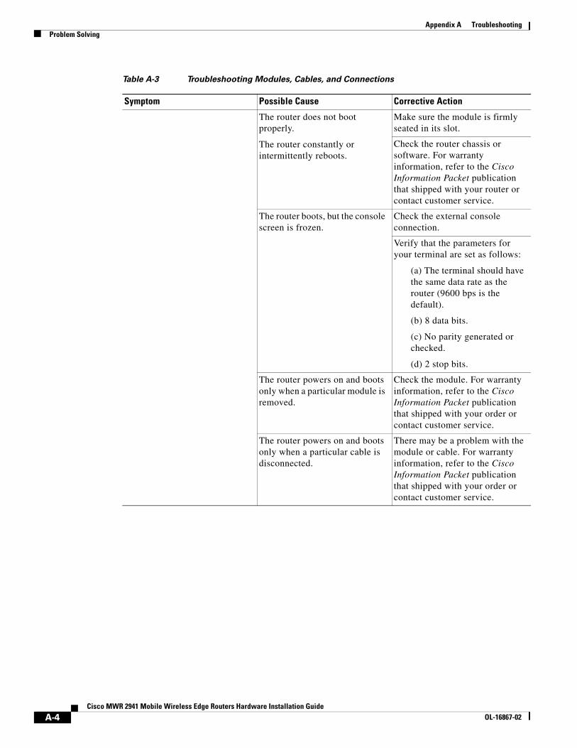
Appendix A TroubleshootingProblem Solving
The router does not boot properly.
The router constantly or intermittently reboots.
Make sure the module is firmly seated in its slot.
Check the router chassis or software. For warranty information, refer to the Cisco Information Packet publication that shipped with your router or contact customer service.
The router boots, but the console screen is frozen.
Check the external console connection.
Verify that the parameters for your terminal are set as follows:
(a) The terminal should have the same data rate as the router (9600 bps is the default).
(b) 8 data bits.
(c) No parity generated or checked.
(d) 2 stop bits.
The router powers on and boots only when a particular module is removed.
Check the module. For warranty information, refer to the Cisco Information Packet publication that shipped with your order or contact customer service.
The router powers on and boots only when a particular cable is disconnected.
There may be a problem with the module or cable. For warranty information, refer to the Cisco Information Packet publication that shipped with your order or contact customer service.
Table A-3 Troubleshooting Modules, Cables, and Connections
Symptom Possible Cause Corrective Action
A-4Cisco MWR 2941 Mobile Wireless Edge Routers Hardware Installation Guide
OL-16867-02
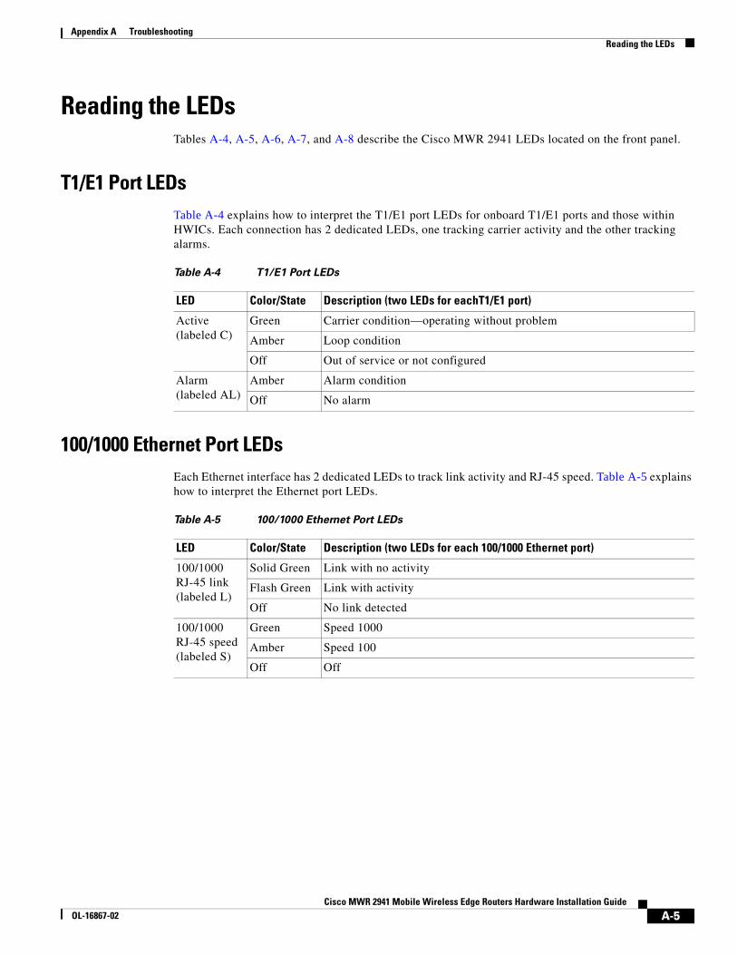
Appendix A TroubleshootingReading the LEDs
Reading the LEDsTables A-4, A-5, A-6, A-7, and A-8 describe the Cisco MWR 2941 LEDs located on the front panel.
T1/E1 Port LEDsTable A-4 explains how to interpret the T1/E1 port LEDs for onboard T1/E1 ports and those within HWICs. Each connection has 2 dedicated LEDs, one tracking carrier activity and the other tracking alarms.
100/1000 Ethernet Port LEDsEach Ethernet interface has 2 dedicated LEDs to track link activity and RJ-45 speed. Table A-5 explains how to interpret the Ethernet port LEDs.
Table A-4 T1/E1 Port LEDs
LED Color/State Description (two LEDs for eachT1/E1 port)
Active (labeled C)
Green Carrier condition—operating without problem
Amber Loop condition
Off Out of service or not configured
Alarm (labeled AL)
Amber Alarm condition
Off No alarm
Table A-5 100/1000 Ethernet Port LEDs
LED Color/State Description (two LEDs for each 100/1000 Ethernet port)
100/1000 RJ-45 link (labeled L)
Solid Green Link with no activity
Flash Green Link with activity
Off No link detected
100/1000 RJ-45 speed (labeled S)
Green Speed 1000
Amber Speed 100
Off Off
A-5Cisco MWR 2941 Mobile Wireless Edge Routers Hardware Installation Guide
OL-16867-02
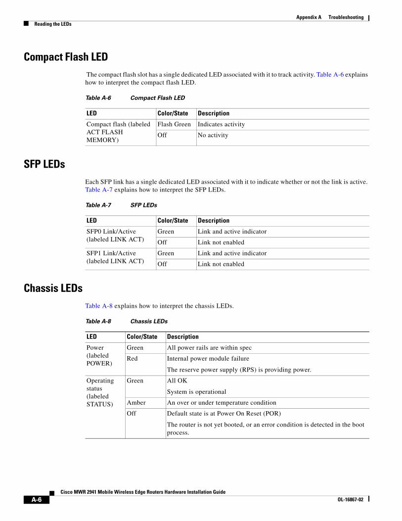
Appendix A TroubleshootingReading the LEDs
Compact Flash LED The compact flash slot has a single dedicated LED associated with it to track activity. Table A-6 explains how to interpret the compact flash LED.
SFP LEDsEach SFP link has a single dedicated LED associated with it to indicate whether or not the link is active. Table A-7 explains how to interpret the SFP LEDs.
Chassis LEDsTable A-8 explains how to interpret the chassis LEDs.
Table A-6 Compact Flash LED
LED Color/State Description
Compact flash (labeled ACT FLASH MEMORY)
Flash Green Indicates activity
Off No activity
Table A-7 SFP LEDs
LED Color/State Description
SFP0 Link/Active (labeled LINK ACT)
Green Link and active indicator
Off Link not enabled
SFP1 Link/Active (labeled LINK ACT)
Green Link and active indicator
Off Link not enabled
Table A-8 Chassis LEDs
LED Color/State Description
Power (labeled POWER)
Green All power rails are within spec
Red Internal power module failure
The reserve power supply (RPS) is providing power.
Operating status (labeled STATUS)
Green All OK
System is operational
Amber An over or under temperature condition
Off Default state is at Power On Reset (POR)
The router is not yet booted, or an error condition is detected in the boot process.
A-6Cisco MWR 2941 Mobile Wireless Edge Routers Hardware Installation Guide
OL-16867-02
Appendix A TroubleshootingReading the LEDs
Activity (labeled ACTIVITY)
Green IOS has booted and packets are being transferred
Amber BootRom has successfully loaded
Off Default state is at POR
No activity occurring
BITS I/F (labeled BITS ACT)
Green Port is up and working properly
Amber Port is disabled, not connected, or not in use
Off Port is faulty or out of service
Table A-8 Chassis LEDs
LED Color/State Description
A-7Cisco MWR 2941 Mobile Wireless Edge Routers Hardware Installation Guide
OL-16867-02

Appendix A TroubleshootingReading the LEDs
A-8Cisco MWR 2941 Mobile Wireless Edge Routers Hardware Installation Guide
OL-16867-02
Cisco MWR 2941 Mobile WirelesOL-16867-02
A
P P E N D I X B Cable SpecificationsIf you prefer to build your own cables, this appendix provides cable specifications for the Cisco MWR 2941 router.
This appendix includes the following sections:
• Gigabit Ethernet Connector Pinouts, page B-1
• T1/E1 Port Pinouts, page B-2
• Console and Auxiliary Port Signals and Pinouts, page B-3
• BITS Pinouts, page B-6
• GPS Port Pinouts, page B-6
• SFP Modules and Cable Specifications, page B-7
• HWICs and Cable Specifications, page B-7
Note Pins not listed in the tables in this appendix are not connected.
Gigabit Ethernet Connector PinoutsThis section illustrates the Gigabit Ethernet RJ-45 connector and lists its pinout and signal descriptions. Note that the RJ-45 ports are capable of operating in both 100BaseT and 1000BaseT modes.
Figure B-1 shows the RJ-45 connector and port, and Table B-1 lists the connector pinouts and signals.
Figure B-1 RJ-45 Connector and Port
2050
53
12345678
B-1s Edge Routers Hardware Installation Guide
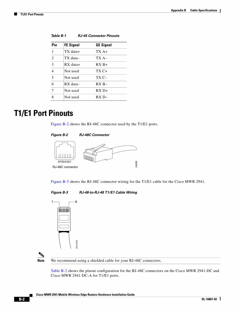
Appendix B Cable SpecificationsT1/E1 Port Pinouts
T1/E1 Port PinoutsFigure B-2 shows the RJ-48C connector used by the T1/E1 ports.
Figure B-2 RJ-48C Connector
Figure B-3 shows the RJ-48C connector wiring for the T1/E1 cable for the Cisco MWR 2941.
Figure B-3 RJ-48-to-RJ-48 T1/E1 Cable Wiring
Note We recommend using a shielded cable for your RJ-48C connectors.
Table B-2 shows the pinout configuration for the RJ-48C connectors on the Cisco MWR 2941-DC and Cisco MWR 2941-DC-A for T1/E1 ports.
Table B-1 RJ-45 Connector Pinouts
Pin FE Signal GE Signal
1 TX data+ TX A+
2 TX data– TX A–
3 RX data+ RX B+
4 Not used TX C+
5 Not used TX C–
6 RX data– RX B–
7 Not used RX D+
8 Not used RX D–
2493
98 7 6 5 4 3 2 1
RJ-48C connector
H11
419
1 8
B-2Cisco MWR 2941 Mobile Wireless Edge Routers Hardware Installation Guide
OL-16867-02
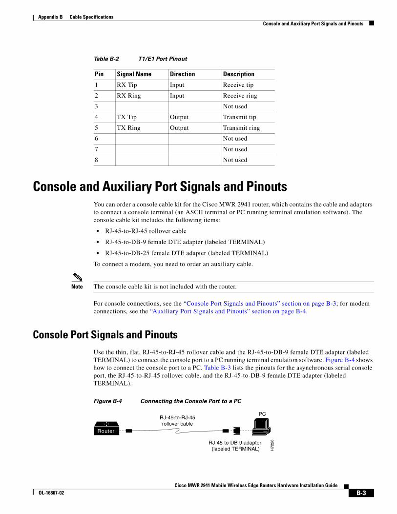
Appendix B Cable SpecificationsConsole and Auxiliary Port Signals and Pinouts
Console and Auxiliary Port Signals and PinoutsYou can order a console cable kit for the Cisco MWR 2941 router, which contains the cable and adapters to connect a console terminal (an ASCII terminal or PC running terminal emulation software). The console cable kit includes the following items:
• RJ-45-to-RJ-45 rollover cable
• RJ-45-to-DB-9 female DTE adapter (labeled TERMINAL)
• RJ-45-to-DB-25 female DTE adapter (labeled TERMINAL)
To connect a modem, you need to order an auxiliary cable.
Note The console cable kit is not included with the router.
For console connections, see the “Console Port Signals and Pinouts” section on page B-3; for modem connections, see the “Auxiliary Port Signals and Pinouts” section on page B-4.
Console Port Signals and PinoutsUse the thin, flat, RJ-45-to-RJ-45 rollover cable and the RJ-45-to-DB-9 female DTE adapter (labeled TERMINAL) to connect the console port to a PC running terminal emulation software. Figure B-4 shows how to connect the console port to a PC. Table B-3 lists the pinouts for the asynchronous serial console port, the RJ-45-to-RJ-45 rollover cable, and the RJ-45-to-DB-9 female DTE adapter (labeled TERMINAL).
Figure B-4 Connecting the Console Port to a PC
Table B-2 T1/E1 Port Pinout
Pin Signal Name Direction Description
1 RX Tip Input Receive tip
2 RX Ring Input Receive ring
3 Not used
4 TX Tip Output Transmit tip
5 TX Ring Output Transmit ring
6 Not used
7 Not used
8 Not used
PC
H72
26
RJ-45-to-RJ-45rollover cable
RJ-45-to-DB-9 adapter (labeled TERMINAL)
Router
B-3Cisco MWR 2941 Mobile Wireless Edge Routers Hardware Installation Guide
OL-16867-02
Appendix B Cable SpecificationsConsole and Auxiliary Port Signals and Pinouts
Table B-4 lists the pinouts for the asynchronous serial console port, the RJ-45-to-RJ-45 rollover cable, and the RJ-45-to-DB-25 female DTE adapter (labeled TERMINAL).
Auxiliary Port Signals and PinoutsTable B-5 lists the pinouts for the asynchronous serial auxiliary port, the RJ-45-to-RJ-45 rollover cable, and the RJ-45-to-DB-25 male DCE adapter (labeled MODEM).
Table B-3 Console Port Signaling and Cabling Using a DB-9 Adapter
ConsolePort (DTE) RJ-45-to-RJ-45 Rollover Cable
RJ-45-to-DB-9Terminal Adapter (Connected to Rollover Cable)
ConsoleDevice
Signal RJ-45 Pin RJ-45 Pin DB-9 Pin Signal
RTS 11
1. Pin 1 is connected internally to pin 8.
8 8 CTS
DTR 2 7 6 DSR/DCD
TxD 3 6 2 RxD
GND/RI 4 5 5 GND
GND 5 4 5 GND/RI
RxD 6 3 3 TxD
DSR/DCD 7 2 4 DTR
CTS 81 1 7 RTS
Table B-4 Console Port Signaling and Cabling Using a DB-25 Adapter
ConsolePort (DTE)1
1. You can use the same cabling to connect a console to the auxiliary port.
RJ-45-to-RJ-45 Rollover CableRJ-45-to-DB-25Terminal Adapter
ConsoleDevice
Signal RJ-45 Pin RJ-45 Pin DB-25 Pin Signal
RTS 12
2. Pin 1 is connected internally to pin 8.
8 5 CTS
DTR 2 7 6 DSR/DCD
TxD 3 6 3 RxD
GND/RI 4 5 7 GND
GND 5 4 7 GND/RI
RxD 6 3 2 TxD
DSR/DCD 7 2 20 DTR
CTS 82 1 4 RTS
B-4Cisco MWR 2941 Mobile Wireless Edge Routers Hardware Installation Guide
OL-16867-02
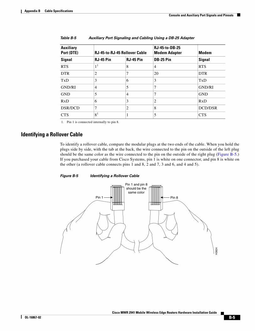
Appendix B Cable SpecificationsConsole and Auxiliary Port Signals and Pinouts
Identifying a Rollover Cable
To identify a rollover cable, compare the modular plugs at the two ends of the cable. When you hold the plugs side by side, with the tab at the back, the wire connected to the pin on the outside of the left plug should be the same color as the wire connected to the pin on the outside of the right plug (Figure B-5.) If you purchased your cable from Cisco Systems, pin 1 is white on one connector, and pin 8 is white on the other (a rollover cable connects pins 1 and 8, 2 and 7, 3 and 6, and 4 and 5).
Figure B-5 Identifying a Rollover Cable
Table B-5 Auxiliary Port Signaling and Cabling Using a DB-25 Adapter
AuxiliaryPort (DTE) RJ-45-to-RJ-45 Rollover Cable
RJ-45-to-DB-25Modem Adapter Modem
Signal RJ-45 Pin RJ-45 Pin DB-25 Pin Signal
RTS 11
1. Pin 1 is connected internally to pin 8.
8 4 RTS
DTR 2 7 20 DTR
TxD 3 6 3 TxD
GND/RI 4 5 7 GND/RI
GND 5 4 7 GND
RxD 6 3 2 RxD
DSR/DCD 7 2 8 DCD/DSR
CTS 81 1 5 CTS
Pin 1 Pin 8
H38
24
Pin 1 and pin 8should be the
same color
B-5Cisco MWR 2941 Mobile Wireless Edge Routers Hardware Installation Guide
OL-16867-02
Appendix B Cable SpecificationsBITS Pinouts
BITS PinoutsTable B-6 lists the pinouts for the BITS interface RJ-48 port on the Cisco MWR 2941-DC.
Table B-6 list the pinouts for the BITS/ToD interface RJ-45 port on the Cisco MWR 2941-DC-A.
GPS Port PinoutsThe Cisco MWR 2941-DC-A has a 10Mhz and a 1PPS GPS port that allow you to configure input or output clocking with a GPS device. Table B-8 summarizes the pinouts for the 10Mhz and 1PPS interfaces.
Note For pinouts related to ToD and 1PPS using the BITS interface, see Console and Auxiliary Port Signals and Pinouts.
Table B-6 BITS Interface Pinouts for the Cisco MWR 2941-DC
Pin Signal Name Direction Description
1 RX ring Input Receive ring
2 RX tip Input Receive tip (T1/E1)
3, 4 Not used —
5 TX ring Not used —
6 TX tip Not used —
7, 8 Not used —
Table B-7 BITS/ToD Pinouts for the Cisco MWR 2941-DA-A
Pin Signal Name Direction Description
1 RX ring Input Receive ring
2 RX tip Input Receive tip (T1/E1)
3 1PPS_N Output 1PPS RS422 output signal.
4, 5 Ground
6 1PPS_P Output 1PPS RS422 output signal.
7 TOD_N Output/Input Time of Day RS422 output or input
8 TOD_P Output/Input Time of Day RS422 output or input
B-6Cisco MWR 2941 Mobile Wireless Edge Routers Hardware Installation Guide
OL-16867-02
Appendix B Cable SpecificationsSFP Modules and Cable Specifications
Note The 1PPS interface type is Series 1.0/2.3, 50 ohms.
For instructions on how to configure the 10 Mhz and 1PPSs ports, see the Cisco MWR 2941 Mobile Wireless Edge Router Software Configuration Guide.
SFP Modules and Cable SpecificationsFor information about SFP modules supported by the Cisco MWR 2941, including pinouts, see the Cisco Interfaces and Modules support section on Cisco.com.
HWICs and Cable SpecificationsFor information about HWICs supported by the Cisco MWR 2941, including pinouts, see
http://www.cisco.com/en/US/products/hw/modules/ps2641/prod_installation_guides_list.html.
Table B-8 GPS Port Pinouts for the Cisco MWR 2941-DC-A
10 Mhz 1PPS
Waveform Input—Sine wave
Output—Square wave
Input—Pulse shape
Output—Pulse shape
Amplitude Input— > 1.7 volt p-p (+8 to +10 dBm)
Output— > 2.4 volts TTL compatible
Input— > 2.4 volts TTL compatible
Output— > 2.4 volts TTL compatible
Impedance 50 ohms 50 ohms
Pulse Width 50% duty cycle 26 microseconds
Rise Time Input—AC coupled
Output—5 nanoseconds
40 nanoseconds
B-7Cisco MWR 2941 Mobile Wireless Edge Routers Hardware Installation Guide
OL-16867-02

Appendix B Cable SpecificationsHWICs and Cable Specifications
B-8Cisco MWR 2941 Mobile Wireless Edge Routers Hardware Installation Guide
OL-16867-02

Cisco MWR 2941 Mobile WirelesOL-16867-02
A
P P E N D I X C Site LogUse the Site Log to provide a record of actions related to installing and maintaining the router. Keep it in an accessible place near the chassis so that those who performs tasks have access to it. Use the Installation Checklist (see the “Installation Checklist” section on page 2-7) to verify the steps in the installation and maintenance of your router. Site Log entries might include the following:
• Installation progress—Make a copy of the Cisco MWR 2941 router Installation Checklist, and insert it into the Site Log. Make entries as you complete each task.
• Upgrade, removal, and maintenance procedures—Use the Site Log as a record of ongoing router maintenance and expansion history. Each time a task is performed on the Cisco MWR 2941 router, update the Site Log to reflect the following:
– Removal or replacement of HWIC interface cards
– Configuration changes
– Maintenance schedules and requirements
– Maintenance procedures performed
– Intermittent problems
– Comments and notes
Table C-1 on page C-2 shows a sample site log. Make copies of the sample or design your own site log to meet the needs of your site and equipment.
C-1s Edge Routers Hardware Installation Guide

Appendix C Site Log
Table C-1 Site Log
Date Description of Action Performed or Symptom Observed Initials
C-2Cisco MWR 2941 Mobile Wireless Edge Routers Hardware Installation Guide
OL-16867-02
Cisco MWR 2941 Mobile WOL-16867-02
I N D E X
Numerics
10Mhz Interface, Connecting cables to 3-13
1PPS Interface, Connecting cables to 3-13
A
activity LED 1-2
adapter pinouts B-4, B-5
audience i-viii
auxiliary port 1-3
adapter pinouts B-5
connecting 3-11
connections 2-8, 2-9, 3-11
pinouts B-4, B-5
auxiliary port signaling cabling, DB-25 (table) B-5
B
back panel 1-5, 3-3, 3-4, 3-6, 3-7, 3-8, 3-9
before you begin
unpacking and checking
shipment 2-5
BITS/TOD/1PPS Interface, Connecting cables to 3-13
BITS activity LED 1-2
BITS Pinouts B-6
C
cable
assemblies B-3
checklist, installation 2-7
Cisco Information Packet publication 2-6
Cisco MWR 2941 Rear View 1-5
compact flash
formatting 3-15
connecting
auxiliary port 3-11
gigabit ethernet interface cables 3-12
network cables 3-11
power supply 3-6
console port 1-3
adapter B-4
connections 2-8, 3-11
considerations 2-8
pinouts B-4
console port signaling cabling, DB-25 (table) B-4
console port signaling cabling, DB-9 (table) B-4
console port signals and pinouts B-3
conventions, documentation i-ix
D
documentation
conventions i-ix
E
equipment
for installation 2-6
racks rack-mounting
equipment 2-4
exposed wires (warning) 3-9
IN-1ireless Edge Routers Hardware Installation Guide
Index
F
formatting compact flash 3-15
Front View 1-3
G
general site requirements 2-3
gigabit ethernet
connecting interface cables 3-12
GPS Cables, Connecting cables to 3-13
GPS Port Pinouts B-6
grounding
(warning) 3-14
MWR 2942-DC router 3-6
H
hardware
installing 3-1
troubleshooting procedures A-1
height of router 1-1
HWIC Cards 1-5
HWICs and Cable Specifications B-7
I
installation
checklist 2-7
hardware 3-1
mounting 3-2
tools required 2-6
interface
numbering 1-8
Interface Numbering 1-8
interface numbering 1-8
IN-2Cisco MWR 2941 Mobile Wireless Edge Routers Hardware Installa
L
LED
chassis 1-2
compact flash 1-2
Ethernet ports 1-2
SFP ports 1-2
T1/E1 ports 1-2
LEDs
front panel A-5
log
site C-1
M
method of procedures
See MOP
MOP 2-5
mounting
instructions 3-2
N
network cables, connecting 3-11
numbering
interface 1-8
P
packet transfers 1-2
Pinouts, GPS Port B-6
power (warning) 2-2
powering on 3-14
power LED 1-2
power lines (warning) 2-2
power supplies (warning) 2-2
power supply
connecting 3-6
tion GuideOL-16867-02
Index
description 1-6
power supply (warning) 3-9, 3-14
problem solving
See troubleshooting
R
Rear View 1-5
record keeping, site log 2-8
regulatory compliance 1-10
restricted access (warning) 2-2, 3-1
rollover cable, identifying B-5
router weight 1-1
S
safety
information 1-10
overview i-x
secure cabling (warning) 3-9
SELV circuits (warning) 1-7, 2-2
SFP Modules and Cable Specifications B-7
shelf-rack 1-1
shipment
unpacking and checking 2-5
site
configuration 2-4
environment 2-4
log C-1
site log, record keeping 2-8
site requirements
MOPs 2-5
specifications
system 1-8
specifications, system 1-8
status LED 1-2
supply tolerance 1-6
system specifications 1-8
Cisco MWR 2941OL-16867-02
T
temperature sensor 1-8
tools required for installation 2-6
troubleshooting
cables A-3
connections A-3
cooling system A-2
front panel LEDs A-5
modules A-3
power system A-2
V
ventilation 2-5
W
warning
short circuit 3-9
warnings
safety overview i-x
IN-3 Mobile Wireless Edge Routers Hardware Installation Guide

Index
IN-4Cisco MWR 2941 Mobile Wireless Edge Routers Hardware Installa
tion GuideOL-16867-02