Embed Size (px)
Citation preview

Cisco MWR 2941 Mobile Wireless Edge Router SOL-21227-02
C H A P T E R 1
Cisco MWR 2941 Router OverviewThe Cisco MWR 2941 Mobile Wireless Router is cell-site access platforms specifically designed to aggregate and transport mixed-generation radio access network (RAN) traffic. The router is used at the cell site edge as a part of a 2G, 3G, or 4G radio access network (RAN). The Cisco MWR 2941 includes the following models:
• Cisco MWR 2941-DC
• Cisco MWR 2941-DC-A
The Cisco MWR 2941 router helps enable a variety of RAN solutions by extending IP connectivity to devices using Global System for Mobile Communications (GSM), General Packet Radio Service (GPRS), Node Bs using HSPA or LTE, base transceiver stations (BTSs) using Enhanced Data Rates for GSM Evolution (EDGE), Code Division Multiple Access (CDMA), CDMA-2000, EVDO, or WiMAX, and other cell-site equipment. It transparently and efficiently transports cell-site voice, data, and signaling traffic over IP using traditional T1/E1 circuits, including leased line, microwave, and satellite, as well as alternative backhaul networks, including Carrier Ethernet, DSL, Ethernet in the First Mile (EFM), and WiMAX. It also supports standards-based Internet Engineering Task Force (IETF) Internet protocols over the RAN transport network, including those standardized at the Third-Generation Partnership Project (3GPP) for IP RAN transport.
Custom designed for the cell site, the Cisco MWR 2941 features a small form factor, extended operating temperature, and cell-site DC input voltages.
Note The Cisco MWR 2941-DC and 2941-DC-A support the same features except for commands related to the 1PPS, 10Mhz, 2.048Mhz, and 1.544Mhz timing ports that are included on the 2941-DC-A. For more information, see the Release Notes for Cisco MWR 2941-DC Mobile Wireless Edge Router for Cisco IOS Release 12.2(33)MRB.
This chapter includes the following sections:
• Introduction, page 1-2
• Features, page 1-3
• Network Management Features, page 1-35
• Limitations and Restrictions, page 1-36
1-1oftware Configuration Guide, Release 12.2(33)MRB

Chapter 1 Cisco MWR 2941 Router Overview Introduction
IntroductionA typical RAN is composed of thousands of base transceiver stations (BTSs)/Node Bs, hundreds of base station controllers/radio network controllers (BSCs/RNCs), and several mobile switching centers (MSCs). The BTS/Node Bs and BSC/RNC are often separated by large geographic distances, with the BTSs/Node Bs located in cell sites uniformly distributed throughout a region, and the BSCs, RNCs, and MSCs located at suitably chosen Central Offices (CO) or mobile telephone switching offices (MTSO).
The traffic generated by a BTS/Node B is transported to the corresponding BSC/RNC across a network, referred to as the backhaul network, which is often a hub-and-spoke topology with hundreds of BTS/Node Bs connected to a BSC/RNC by point-to-point time division multiplexing (TDM) trunks. These TDM trunks may be leased-line T1/E1s or their logical equivalents, such as microwave links or satellite channels.
RAN Transport SolutionsThe Cisco MWR 2941 Mobile Wireless Router supports a variety of RAN transport solutions, including the following:
• IP/Multiprotocol Label Switching (MPLS) RAN backhaul: Allows you to create a high-speed backhaul for a variety of traffic types, including GSM, CDMA, HSPA/LTE, CDMA, EVDO, and WiMAX networks.
• Cell-site operations support networks: Facilitates telemetry to cell sites for remote operations and network element management.
• Cell-site IP points of presence (POPs): Allows you to offer IP services and applications at cell sites.
• Carrier Ethernet features including Resilient Ethernet Protocol (REP), Ethernet Connectivity Fault Management (CFM), Ethernet Local Management Interface (E-LMI), and Ethernet Operations, Administration, and Maintenance (OAM).
• Network clocking features including PTP, pseudowire-based clocking, and synchronous Ethernet.
• Flexible backhaul transport including MLPPP over T1, E1, xDSL, and Ethernet.
1-2Cisco MWR 2941 Mobile Wireless Edge Router Software Configuration Guide, Release 12.2(33)MRB
OL-21227-02

Chapter 1 Cisco MWR 2941 Router Overview Features
FeaturesThe following sections describe the features available in the Cisco MWR 2941 router.
Cisco Pseudowire Emulation Edge-to-EdgeCisco Pseudowire Emulation Edge-to-Edge (PWE3) allows you to transport traffic using traditional services such as E1/T1 over a packet-based backhaul technology such as MPLS or IP. A pseudowire (PW) consists of a connection between two provider edge (PE) devices that connects two attachment circuits (ACs), such as ATM VPIs/VCIs or E1/T1 links. Figure 1-1 shows a sample pseudowire topology.
Figure 1-1 Cisco MWR 2941 Router in a PWE3—Example
PWs manage encapsulation, timing, order, and other operations in order to make it transparent to users; the PW tunnel appears as an unshared link or circuit of the emulated service.
There are limitations that impede some applications from utilizing a PW connection. For more information, see the section describing the PW service.
Cisco supports the following standards-based PWE types:
• Structure-agnostic TDM over Packet, page 1-3
• Structure-aware TDM Circuit Emulation Service over Packet-Switched Network, page 1-4
• Transportation of Service Using ATM over MPLS, page 1-4
• Transportation of Service Using Ethernet over MPLS, page 1-4
Structure-agnostic TDM over Packet
SAToP encapsulates TDM bit-streams (T1, E1, T3, E3) as PWs over PSNs. It disregards any structure that may be imposed on streams, in particular the structure imposed by the standard TDM framing.
The protocol used for emulation of these services does not depend on the method in which attachment circuits are delivered to the PEs. For example, a T1 attachment circuit is treated the same way for all delivery methods, including: PE on copper, multiplex in a T3 circuit, mapped into a virtual tributary of
ATM/TDM ATM/TDMxconnectxconnect
MPLS/IP
Pseudowire
Emulated Circuit
2744
62
1-3Cisco MWR 2941 Mobile Wireless Edge Router Software Configuration Guide, Release 12.2(33)MRB
OL-21227-02

Chapter 1 Cisco MWR 2941 Router Overview Features
a SONET/SDH circuit, or carried over a network using unstructured Circuit Emulation Service (CES). Termination of specific carrier layers used between the PE and circuit emulation (CE) is performed by an appropriate network service provider (NSP).
For instructions on how to configure SAToP, see the “Configuring Structure-Agnostic TDM over Packet (SAToP)” section on page 4-79. For a sample SAToP configuration, see the “TDM over MPLS Configuration” section on page A-14.
Structure-aware TDM Circuit Emulation Service over Packet-Switched Network
CESoPSN encapsulates structured (NxDS0) TDM signals as PWs over PSNs. It complements similar work for structure-agnostic emulation of TDM bit-streams, such as PWE3-SAToP.
Emulation of NxDS0 circuits saves PSN bandwidth and supports DS0-level grooming and distributed cross-connect applications. It also enhances resilience of CE devices due to the effects of loss of packets in the PSN.
CESoPSN supports channel-associated signaling (CAS) for E1 and T1 interfaces. CAS provides signaling information within each DS0 channel as opposed to using a separate signaling channel. CAS also referred to as in-band signaling or robbed bit signaling.
For instructions on how to configure SAToP, see the “Configuring Circuit Emulation Service over Packet-Switched Network (CESoPSN)” section on page 4-79. For a sample SAToP configuration, see the “TDM over MPLS Configuration” section on page A-14.
Transportation of Service Using ATM over MPLS
An Asynchronous Transfer Mode (ATM) over MPLS PW is used to carry ATM cells over an MPLS network. It is an evolutionary technology that allows you to migrate packet networks from legacy networks, yet provides transport for legacy applications. ATM over MPLS is particularly useful for transporting 3G voice traffic over MPLS networks.
You can configure ATM over MPLS in the following modes:
• N-to-1 Cell Mode—Maps one or more ATM virtual channel connections (VCCs) or virtual permanent connection (VPCs) to a single pseudowire.
• 1-to-1 Cell Mode—Maps a single ATM VCC or VPC to a single pseudowire.
• Port Mode—Map one physical port to a single pseudowire connection.
The Cisco MWR 2941 also supports cell packing and PVC mapping for ATM over MPLS pseudowires.
For more information about how to configure ATM over MPLS, see the “Configuring Transportation of Service Using ATM over MPLS” section on page 4-80. For sample ATM over MPLS configurations, see the “ATM over MPLS Configuration” section on page A-17.
Transportation of Service Using Ethernet over MPLS
Ethernet over MPLS (EoMPLS) PWs provide a tunneling mechanism for Ethernet traffic through an MPLS-enabled Layer 3 core network. EoMPLS PWs encapsulate Ethernet protocol data units (PDUs) inside MPLS packets and use label switching to forward them across an MPLS network. EoMPLS PWs are an evolutionary technology that allows you to migrate packet networks from legacy networks while providing transport for legacy applications. EoMPLS PWs also simplify provisioning, since the provider edge equipment only requires Layer 2 connectivity to the connected customer edge (CE) equipment. The Cisco MWR 2941 implementation of EoMPLS PWs is compliant with the RFC 4447 and 4448 standards.
1-4Cisco MWR 2941 Mobile Wireless Edge Router Software Configuration Guide, Release 12.2(33)MRB
OL-21227-02

Chapter 1 Cisco MWR 2941 Router Overview Features
For instructions on how to create an EoMPLS PW, see the “Configuring Transportation of Service Using Ethernet over MPLS” section on page 4-87.
Limitations
When configuring an EoMPLS pseudowire on the Cisco MWR 2941, you cannot configure an IP address on the same interface as the pseudowire.
Generic Routing Encapsulation (GRE) Tunneling
Generic routing encapsulation (GRE) is a tunneling protocol developed by Cisco that can encapsulate a wide variety of protocol packet types inside IP tunnels, creating a virtual point-to-point link to Cisco routers at remote points over an IP internetwork. GRE tunneling allows you to transport a pseudowire over an IP backhaul network when MPLS routing is not available between a cell site (BTS or Node-B) and an aggregation point (BSC or RNC). The Cisco MWR 2941 supports GRE encapsulation for the following PW connection types:
• ATM over MPLS
• SAToP
• CESoPSN
• Ethernet over MPLS
The Cisco MWR 2941 implementation of GRE can interoperate with the Cisco 7600 router and provides compliance with RFCs 2784 and 4023. The Cisco MWR 2941 supports up to 128 GRE tunnels. For more information about how to configure GRE tunneling, see the “Configuring GRE Tunneling” section on page 4-76.
Resilient Ethernet Protocol (REP)
A REP segment is a chain of ports connected to each other and configured with a segment ID. Each segment consists of standard (nonedge) segment ports and two user-configured edge ports. A switch can have only two ports belonging to the same segment, and each segment port can have only one external neighbor. A segment can go through a shared medium, but on any link, only two ports can belong to the same segment. REP is supported only on Layer 2 trunk interfaces.
Figure 1-2 shows an example of a segment consisting of six ports spread across four switches. Ports E1 and E2 are configured as edge ports. When all ports are operational (as in the segment on the left), a single port is blocked, shown by the diagonal line. When there is a network failure, as shown in the diagram on the right, the blocked port returns to the forwarding state to minimize network disruption.
1-5Cisco MWR 2941 Mobile Wireless Edge Router Software Configuration Guide, Release 12.2(33)MRB
OL-21227-02
Chapter 1 Cisco MWR 2941 Router Overview Features
Figure 1-2 REP Open Segments
Figure 1-2 shows an open segment; there is no connectivity between the two edge ports. The REP segment cannot cause a bridging loop, and you can safely connect the segment edges to any network. All hosts connected to switches inside the segment have two possible connections to the rest of the network through the edge ports, but only one connection is accessible at any time. If a host cannot access its usual gateway because of a failure, REP unblocks all ports to ensure that connectivity is available through the other gateway.
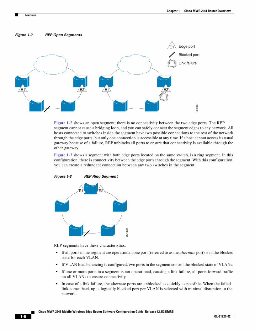
Figure 1-3 shows a segment with both edge ports located on the same switch, is a ring segment. In this configuration, there is connectivity between the edge ports through the segment. With this configuration, you can create a redundant connection between any two switches in the segment.
Figure 1-3 REP Ring Segment
REP segments have these characteristics:
• If all ports in the segment are operational, one port (referred to as the alternate port) is in the blocked state for each VLAN.
• If VLAN load balancing is configured, two ports in the segment control the blocked state of VLANs.
• If one or more ports in a segment is not operational, causing a link failure, all ports forward traffic on all VLANs to ensure connectivity.
• In case of a link failure, the alternate ports are unblocked as quickly as possible. When the failed link comes back up, a logically blocked port per VLAN is selected with minimal disruption to the network.
E2E1 E2E1
E1 Edge port
Blocked port
Link failure
2018
88
E2E1
2018
89
1-6Cisco MWR 2941 Mobile Wireless Edge Router Software Configuration Guide, Release 12.2(33)MRB
OL-21227-02

Chapter 1 Cisco MWR 2941 Router Overview Features
You can construct almost any type of network based on REP segments. REP also supports VLAN load-balancing, controlled by the primary edge port but occurring at any port in the segment.
REP has these limitations:
• You must configure each segment port; an incorrect configuration can cause forwarding loops in the networks.
• REP can manage only a single failed port within the segment; multiple port failures within the REP segment cause loss of network connectivity.
• You should configure REP only in networks with redundancy. Configuring REP in a network without redundancy causes loss of connectivity.
Link Integrity
REP does not use an end-to-end polling mechanism between edge ports to verify link integrity. It implements local link failure detection. The REP Link Status Layer (LSL) detects its REP-aware neighbor and establishes connectivity within the segment. All VLANs are blocked on an interface until it detects the neighbor. After the neighbor is identified, REP determines which neighbor port should become the alternate port and which ports should forward traffic.
Each port in a segment has a unique port ID. The port ID format is similar to that used by the spanning tree algorithm: a port number (unique on the bridge), associated to a MAC address (unique in the network). When a segment port is coming up, its LSL starts sending packets that include the segment ID and the port ID. The port is declared operational after it performs a three-way handshake with a neighbor in the same segment.
A segment port does not become operational if:
• No neighbor has the same segment ID.
• More than one neighbor has the same segment ID.
• The neighbor does not acknowledge the local port as a peer.
Each port creates an adjacency with its immediate neighbor. After the neighbor adjacencies are created, the ports negotiate to determine one blocked port for the segment, the alternate port. All other ports become unblocked. By default, REP packets are sent to a BPDU class MAC address. The packets can also be sent to the Cisco multicast address, which is used only to send blocked port advertisement (BPA) messages when there is a failure in the segment. The packets are dropped by devices not running REP.
Fast Convergence
Because REP runs on a physical link basis and not on a per-VLAN basis, only one hello message is required for all VLANs, reducing the load on the protocol. We recommend that you create VLANs consistently on all switches in a given segment and configure the same allowed VLANs on the REP trunk ports. To avoid the delay introduced by relaying messages in software, REP also allows some packets to be flooded to a regular multicast address. These messages operate at the hardware flood layer (HFL) and are flooded to the whole network, not just the REP segment. Switches that do not belong to the segment treat them as data traffic. You can control flooding of these messages by configuring a dedicated administrative VLAN for the whole domain.
The estimated convergence recovery time on fiber interfaces is less than 200 ms for the local segment with 200 VLANs configured. Convergence for VLAN load balancing is 300 ms or less.
1-7Cisco MWR 2941 Mobile Wireless Edge Router Software Configuration Guide, Release 12.2(33)MRB
OL-21227-02
Chapter 1 Cisco MWR 2941 Router Overview Features
VLAN Load Balancing
One edge port in the REP segment acts as the primary edge port; the other as the secondary edge port. The primary edge port always participates in VLAN load balancing in the segment. REP VLAN balancing is achieved by blocking some VLANs at a configured alternate port and all other VLANs at the primary edge port. When you configure VLAN load balancing, you can specify the alternate port in one of three ways:
• Enter the port ID of the interface. To identify the port ID of a port in the segment, enter the show interface rep detail interface configuration command for the port.
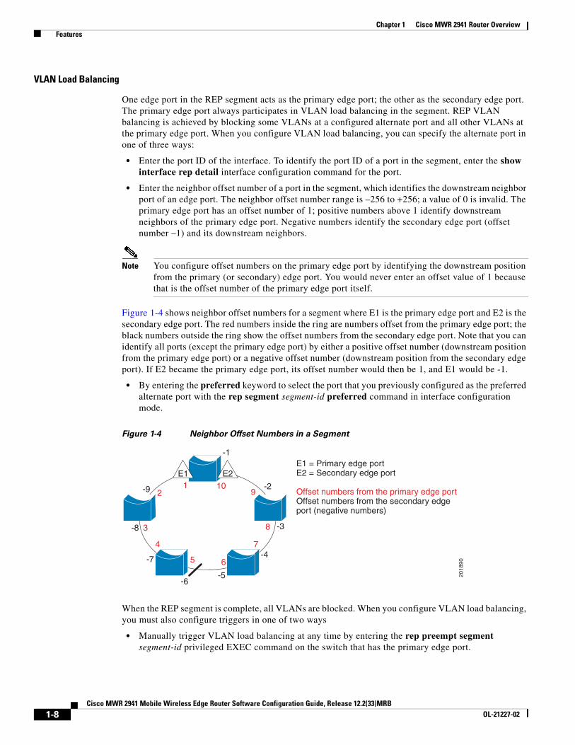
• Enter the neighbor offset number of a port in the segment, which identifies the downstream neighbor port of an edge port. The neighbor offset number range is –256 to +256; a value of 0 is invalid. The primary edge port has an offset number of 1; positive numbers above 1 identify downstream neighbors of the primary edge port. Negative numbers identify the secondary edge port (offset number –1) and its downstream neighbors.
Note You configure offset numbers on the primary edge port by identifying the downstream position from the primary (or secondary) edge port. You would never enter an offset value of 1 because that is the offset number of the primary edge port itself.
Figure 1-4 shows neighbor offset numbers for a segment where E1 is the primary edge port and E2 is the secondary edge port. The red numbers inside the ring are numbers offset from the primary edge port; the black numbers outside the ring show the offset numbers from the secondary edge port. Note that you can identify all ports (except the primary edge port) by either a positive offset number (downstream position from the primary edge port) or a negative offset number (downstream position from the secondary edge port). If E2 became the primary edge port, its offset number would then be 1, and E1 would be -1.
• By entering the preferred keyword to select the port that you previously configured as the preferred alternate port with the rep segment segment-id preferred command in interface configuration mode.
Figure 1-4 Neighbor Offset Numbers in a Segment
When the REP segment is complete, all VLANs are blocked. When you configure VLAN load balancing, you must also configure triggers in one of two ways
• Manually trigger VLAN load balancing at any time by entering the rep preempt segment segment-id privileged EXEC command on the switch that has the primary edge port.
E2E1
-1
-2
-3
-4
-5-6
-7
-8
-9 21 10
9
8
7
65
4
3
2018
90E1 = Primary edge portE2 = Secondary edge port
Offset numbers from the primary edge portOffset numbers from the secondary edgeport (negative numbers)
1-8Cisco MWR 2941 Mobile Wireless Edge Router Software Configuration Guide, Release 12.2(33)MRB
OL-21227-02

Chapter 1 Cisco MWR 2941 Router Overview Features
• Configure a preempt delay time by entering the rep preempt delay seconds interface configuration command. After a link failure and recovery, VLAN load balancing begins after the configured preemption time period elapses. Note that the delay timer restarts if another port fails before the time has elapsed.
Note When VLAN load balancing is configured, it does not start working until triggered by either manual intervention or a link failure and recovery.
When VLAN load balancing is triggered, the primary edge port sends a message to alert all interfaces in the segment about the preemption. When the secondary port receives the message, it is reflected into the network to notify the alternate port to block the set of VLANs specified in the message and to notify the primary edge port to block the remaining VLANs.
You can also configure a particular port in the segment to block all VLANs. Only the primary edge port initiates VLAN load balancing, which is not possible if the segment is not terminated by an edge port on each end. The primary edge port determines the local VLAN load balancing configuration.
Reconfigure the primary edge port to reconfigure load balancing. When you change the load balancing configuration, the primary edge port again waits for the rep preempt segment command or for the configured preempt delay period after a port failure and recovery before executing the new configuration. If you change an edge port to a regular segment port, the existing VLAN load balancing status does not change. Configuring a new edge port might cause a new topology configuration.
Spanning Tree Interaction
REP does not interact with STP or with the Flex Link feature, but can coexist with both. A port that belongs to a segment is removed from spanning tree control and STP BPDUs are not accepted or sent from segment ports.
To migrate from an STP ring configuration to REP segment configuration, begin by configuring a single port in the ring as part of the segment, and continue by configuring contiguous ports to minimize the number of segments. Each segment always contains a blocked port, so multiple segments means multiple blocked ports and a potential loss of connectivity. When the segment has been configured in both directions to the edge ports, you then configure the edge ports.
REP Ports
Ports in REP segments are Failed, Open, or Alternate.
• A port configured as a regular segment port starts as a failed port.
• After the neighbor adjacencies are determined, the port changes to alternate port state, blocking all VLANs on the interface. Blocked port negotiations occur and when the segment settles, one blocked port remains in the alternate role, and all other ports become open ports.
• When a failure occurs in a link, all ports move to the open state. When the alternate port receives the failure notification, it changes to the open state, forwarding all VLANs.
A regular segment port converted to an edge port, or an edge port converted to a regular segment port, does not always result in a topology change. If you convert an edge port into a regular segment port, VLAN load balancing is not implemented unless it has been configured. For VLAN load balancing, you must configure two edge ports in the segment.
A segment port that is reconfigured as a spanning tree port restarts according the spanning tree configuration. By default, this is a designated blocking port. If PortFast is configured or if STP is disabled, the port goes into the forwarding state.
1-9Cisco MWR 2941 Mobile Wireless Edge Router Software Configuration Guide, Release 12.2(33)MRB
OL-21227-02

Chapter 1 Cisco MWR 2941 Router Overview Features
For instructions on how to configure REP, see the “Configuring Resilient Ethernet Protocol (REP)” section on page 4-15.
Ethernet Operations, Administration, and Maintenance (OAM)Ethernet Operations, Administration, and Maintenance (OAM) is a protocol for installing, monitoring, and troubleshooting Ethernet metropolitan-area networks (MANs) and Ethernet WANs. It relies on a new, optional sublayer in the data link layer of the Open Systems Interconnection (OSI) model. The OAM features covered by this protocol are Discovery, Link Monitoring, Remote Fault Detection, Remote Loopback, and Cisco Proprietary Extensions.
The following sections describe the Ethernet OAM features supported on the Cisco MWR 2941:
• Overview
• Link OAM
• Ethernet Connectivity Fault Management (CFM)
• Ethernet Local Management Interface (E-LMI)
Overview
Ethernet OAM is a protocol for installing, monitoring, and troubleshooting metro Ethernet networks and Ethernet WANs. It relies on a new, optional sublayer in the data link layer of the OSI model. Ethernet OAM can be implemented on any full-duplex point-to-point or emulated point-to-point Ethernet link. A system-wide implementation is not required; OAM can be deployed on particular interfaces for part of a system.
Normal link operation does not require Ethernet OAM. OAM frames, called OAM protocol data units (PDUs), use the slow protocol destination MAC address 0180.c200.0002. They are intercepted by the MAC sublayer and cannot propagate beyond a single hop within an Ethernet network.
Ethernet OAM is a relatively slow protocol with modest bandwidth requirements. The frame transmission rate is limited to a maximum of 10 frames per second; therefore, the impact of OAM on normal operations is negligible. However, when link monitoring is enabled, the CPU must poll error counters frequently. In this case, the required CPU cycles will be proportional to the number of interfaces that have to be polled.
Two major components, the OAM client and the OAM sublayer, make up Ethernet OAM. The following sections describe these components.
OAM Client
The OAM client is responsible for establishing and managing Ethernet OAM on a link. The OAM client also enables and configures the OAM sublayer. During the OAM discovery phase, the OAM client monitors OAM PDUs received from the remote peer and enables OAM functionality on the link based on local and remote state as well as configuration settings. Beyond the discovery phase (at steady state), the OAM client is responsible for managing the rules of response to OAM PDUs and managing the OAM remote loopback mode.
1-10Cisco MWR 2941 Mobile Wireless Edge Router Software Configuration Guide, Release 12.2(33)MRB
OL-21227-02

Chapter 1 Cisco MWR 2941 Router Overview Features
OAM Sublayer
The OAM sublayer presents two standard IEEE 802.3 MAC service interfaces: one facing toward the superior sublayers, which include the MAC client (or link aggregation), and the other interface facing toward the subordinate MAC control sublayer. The OAM sublayer provides a dedicated interface for passing OAM control information and OAM PDUs to and from a client.
The OAM sublayer is made up of three components: control block, multiplexer, and packet parser (p-parser). Each component is described in the following sections.
Control Block
The control block provides the interface between the OAM client and other blocks internal to the OAM sublayer. The control block incorporates the discovery process, which detects the existence and capabilities of remote OAM peers. It also includes the transmit process that governs the transmission of OAM PDUs to the multiplexer and a set of rules that govern the receipt of OAM PDUs from the p-parser.
Multiplexer
The multiplexer manages frames generated (or relayed) from the MAC client, control block, and p-parser. The multiplexer passes through frames generated by the MAC client untouched. It passes OAM PDUs generated by the control block to the subordinate sublayer; for example, the MAC sublayer. Similarly, the multiplexer passes loopback frames from the p-parser to the same subordinate sublayer when the interface is in OAM remote loopback mode.
P-Parser
The p-parser classifies frames as OAM PDUs, MAC client frames, or loopback frames and then dispatches each class to the appropriate entity. OAM PDUs are sent to the control block. MAC client frames are passed to the superior sublayer. Loopback frames are dispatched to the multiplexer.
Link OAM
Link OAM is defined in the IEEE 802.3ah and IEEE 802.3 Clause 57 standards and provides for discovery, Link Monitoring, Remote Fault Indication, Remote Loopback, and Cisco proprietary extensions. The following sections describe Link OAM:
• Discovery
• Link Monitoring
• Remote Failure Indication
• Remote Loopback
• Cisco Vendor-Specific Extensions
• OAM Messages
Discovery
Discovery is the first phase of Ethernet OAM and it identifies the devices in the network and their OAM capabilities. Discovery uses information OAM PDUs. During the discovery phase, the following information is advertised within periodic information OAM PDUs:
• OAM mode—Conveyed to the remote OAM entity. The mode can be either active or passive and can be used to determine device functionality.
1-11Cisco MWR 2941 Mobile Wireless Edge Router Software Configuration Guide, Release 12.2(33)MRB
OL-21227-02

Chapter 1 Cisco MWR 2941 Router Overview Features
• OAM configuration (capabilities)—Advertises the capabilities of the local OAM entity. With this information a peer can determine what functions are supported and accessible; for example, loopback capability.
• OAM PDU configuration—Includes the maximum OAM PDU size for receipt and delivery. This information along with the rate limiting of 10 frames per second can be used to limit the bandwidth allocated to OAM traffic.
• Platform identity—A combination of an organization unique identifier (OUI) and 32-bits of vendor-specific information. OUI allocation, controlled by the IEEE, is typically the first three bytes of a MAC address.
Discovery includes an optional phase in which the local station can accept or reject the configuration of the peer OAM entity. For example, a node may require that its partner support loopback capability to be accepted into the management network. These policy decisions may be implemented as vendor-specific extensions.
Link Monitoring
Link monitoring in Ethernet OAM detects and indicates link faults under a variety of conditions. Link monitoring uses the event notification OAM PDU and sends events to the remote OAM entity when there are problems detected on the link. The error events include the following:
• Error Symbol Period (error symbols per second)—The number of symbol errors that occurred during a specified period exceeded a threshold. These errors are coding symbol errors.
• Error Frame (error frames per second)—The number of frame errors detected during a specified period exceeded a threshold.
• Error Frame Period (error frames per n frames)—The number of frame errors within the last n frames has exceeded a threshold.
• Error Frame Seconds Summary (error seconds per m seconds)—The number of error seconds (1-second intervals with at least one frame error) within the last m seconds has exceeded a threshold.
Because IEEE 802.3ah OAM does not provide a guaranteed delivery of any OAM PDU, the event notification OAM PDU may be sent multiple times to reduce the probability of a lost notification. A sequence number is used to recognize duplicate events.
Remote Failure Indication
Faults in Ethernet connectivity that are caused by slowly deteriorating quality are difficult to detect. Ethernet OAM provides a mechanism for an OAM entity to convey these failure conditions to its peer via specific flags in the OAM PDU. The following failure conditions can be communicated:
• Link Fault—Loss of signal is detected by the receiver; for instance, the peer's laser is malfunctioning. A link fault is sent once per second in the information OAM PDU. Link fault applies only when the physical sublayer is capable of independently transmitting and receiving signals.
• Dying Gasp—An unrecoverable condition has occurred; for example, a power failure. This type of condition is vendor specific. A notification about the condition may be sent immediately and continuously.
• Critical Event—An unspecified critical event has occurred. This type of event is vendor specific. A critical event may be sent immediately and continuously.
1-12Cisco MWR 2941 Mobile Wireless Edge Router Software Configuration Guide, Release 12.2(33)MRB
OL-21227-02

Chapter 1 Cisco MWR 2941 Router Overview Features
Remote Loopback
An OAM entity can put its remote peer into loopback mode using the loopback control OAM PDU. Loopback mode helps an administrator ensure the quality of links during installation or when troubleshooting. In loopback mode, every frame received is transmitted back on the same port except for OAM PDUs and pause frames. The periodic exchange of OAM PDUs must continue during the loopback state to maintain the OAM session.
The loopback command is acknowledged by responding with an information OAM PDU with the loopback state indicated in the state field. This acknowledgement allows an administrator, for example, to estimate if a network segment can satisfy a service-level agreement. Acknowledgement makes it possible to test delay, jitter, and throughput.
When an interface is set to the remote loopback mode the interface no longer participates in any other Layer 2 or Layer 3 protocols such as Spanning Tree Protocol (STP) or Open Shortest Path First (OSPF). The reason is that when two connected ports are in a loopback session, no frames other than the OAM PDUs are sent to the CPU for software processing. The non-OAM PDU frames are either looped back at the MAC level or discarded at the MAC level.
From a user's perspective, an interface in loopback mode is in a link-up state.
Cisco Vendor-Specific Extensions
Ethernet OAM allows vendors to extend the protocol by allowing them to create their own type-length-value (TLV) fields.
OAM Messages
Ethernet OAM messages or OAM PDUs are standard length, untagged Ethernet frames within the normal frame length bounds of 64 to 1518 bytes. The maximum OAM PDU frame size exchanged between two peers is negotiated during the discovery phase.
OAM PDUs always have the destination address of slow protocols (0180.c200.0002) and an Ethertype of 8809. OAM PDUs do not go beyond a single hop and have a hard-set maximum transmission rate of 10 OAM PDUs per second. Some OAM PDU types may be transmitted multiple times to increase the likelihood that they are successfully received on a deteriorating link.
Four types of OAM messages are supported:
• Information OAM PDU—A variable-length OAM PDU that is used for discovery. This OAM PDU includes local, remote, and organization-specific information.
• Event notification OAM PDU—A variable-length OAM PDU that is used for link monitoring. This type of OAM PDU may be transmitted multiple times to increase the chance of a successful receipt; for example, in the case of high-bit errors. Event notification OAM PDUs also may include a time stamp when generated.
• Loopback control OAM PDU—An OAM PDU fixed at 64 bytes in length that is used to enable or disable the remote loopback command.
• Vendor-specific OAM PDU—A variable-length OAM PDU that allows the addition of vendor-specific extensions to OAM.
For instructions on how to configure Ethernet Link OAM, see the “Configuring Ethernet Link Operations, Administration, and Maintenance (OAM)” section on page 4-33.
1-13Cisco MWR 2941 Mobile Wireless Edge Router Software Configuration Guide, Release 12.2(33)MRB
OL-21227-02

Chapter 1 Cisco MWR 2941 Router Overview Features
Ethernet Connectivity Fault Management (CFM)
The Cisco MWR 2941 supports Ethernet Connectivity Fault Management (CFM) as defined in 802.1ag Draft 1.0. Ethernet Connectivity Fault Management (CFM) is an end-to-end per-service-instance Ethernet layer operations, administration, and maintenance (OAM) protocol. It includes proactive connectivity monitoring, fault verification, and fault isolation for large Ethernet metropolitan-area networks (MANs) and WANs.
Ethernet CFM provides the following benefits:
• End-to-end service-level OAM technology
• Reduced operating expense for service provider Ethernet networks
• Competitive advantage for service providers
Note Release 12.2(33)MRA supports the Draft 1.0 version of Ethernet CFM; it does not support the IEEE 802.1ag-2007 version.
For instructions on how to configure CFM, see the “Configuring Ethernet CFM” section on page 4-30.
Ethernet Local Management Interface (E-LMI)
Ethernet Local Management Interface (LMI) is an Ethernet layer operation, administration, and management (OAM) protocol. It provides information that enables autoconfiguration of customer edge (CE) devices and provides the status of Ethernet virtual connections (EVCs) for large Ethernet metropolitan-area networks (MANs) and WANs. Specifically, Ethernet LMI notifies a CE device of the operating state of an EVC and the time when an EVC is added or deleted. Ethernet LMI also communicates the attributes of an EVC and a user-network interface (UNI) to a CE device.
For instructions on how to configure E-LMI, see the “Configuring Ethernet Local Management Interface (E-LMI)” section on page 4-38.
Clocking and TimingThe following sections describe the clocking and timing features available on the Cisco MWR 2941.
• Network Clocking Overview
• Precision Timing Protocol (PTP)
• Pseudowire-based Clocking
• Synchronous Ethernet
Network Clocking Overview
Clock synchronization is important for a variety of applications, including synchronization of radio cell towers. While legacy TDM protocols incorporate timing features, packet-switched networks such as Ethernet do not natively include these features. The Cisco MWR 2941 supports legacy TDM technologies while supporting a variety of technologies that distribute clocking information over packet-switched networks.
1-14Cisco MWR 2941 Mobile Wireless Edge Router Software Configuration Guide, Release 12.2(33)MRB
OL-21227-02

Chapter 1 Cisco MWR 2941 Router Overview Features
Clocking is typically distributed from the core network outward to the BTS or Node B at the network edge. The Cisco MWR 2941 receives and transmits clocking information using any of the following ports:
• T1/E1
• Ethernet (GigabitEthernet and FastEthernet)
• DSL
• BITS/SYNC port
• 1PPS
• 1.544Mhz
• 2.048Mhz
• 10Mhz
Precision Timing Protocol (PTP)
The Cisco MWR 2941 supports the Precision Time Protocol (PTP) as defined by the IEEE 1588-2008 standard. PTP provides for accurate time synchronization on over packet-switched networks. Nodes within a PTP network can act in one of the following roles:
• Grandmaster—A device on the network physically attached to the primary time source. All other clocks are ultimately synchronized to the grandmaster clock.
• Ordinary clock—An ordinary clock is a 1588 clock with a single PTP port that can serve in one of the following roles:
– Master mode—Distributes timing information over the network to one or more slave clocks, thus allowing the slave to synchronize its clock to the master.
– Slave mode—Synchronizes its clock to a master clock.
• Boundary clock—The device participates in selecting the best master clock and can act as the master clock if no better clocks are detected.
• Transparent clock—A device such as a switch that calculates the time it requires to forward traffic and updates the PTP time correction field to account for the delay, making the device transparent in terms of timing calculations.
Note The Cisco MWR 2941 does not currently act as a boundary clock or a transparent clock.
Note The 1588-2008 standard defines other clocking devices that are not described here.
PTP Domains
PTP devices use a best master clock algorithm to determine the most accurate clock on a network and construct a clocking hierarchy based on the grandmaster clock. A given clocking hierarchy is called a PTP domain.
1-15Cisco MWR 2941 Mobile Wireless Edge Router Software Configuration Guide, Release 12.2(33)MRB
OL-21227-02
Chapter 1 Cisco MWR 2941 Router Overview Features
Clock synchronization
PTP master devices periodically launch an exchange of messages with slave devices to help each slave clock recompute the offset between its clock and the master clock. Periodic clock synchronization mitigates any drift between the master and slave clocks.
PTP Redundancy
The Cisco MWR 2941 supports the multicast- and unicast-based timing as specified in the 1588-2008 standard. The Cisco MWR 2941 can use multicast routing to establish redundant paths between an external PTP client and one or more PTP multicast master clocks.
When configured as a multicast PTP router, the Cisco MWR 2941 selects the best path toward a Rendezvous Point (RP) using the active routing protocol, sends a Cisco Protocol Independent Multicast (PIM) join message to the RP, and forwards PTP multicast messages to the PTP client. The Cisco MWR 2941 also supports PIM forwarding. For instructions on how to configure PTP redundancy using multicast, see the “Configuring IP Multicast” section on page 4-64.
Hot Standby Master Clock
The Cisco MWR 2941 supports a hot standby master clock for PTP clocking; the Cisco MWR 2941 selects the best clock source between two PTP master clocks and switches dynamically between them if the clock quality of the standby clock is greater than that of the current master clock. For instructions on how to configure a hot standby master clock, see the “Configuring PTP Clocking” section on page 4-39.
Hybrid Clocking
The Cisco MWR 2941 supports a hybrid clocking mode that uses clock frequency obtained from the synchronous Ethernet port while using phase (ToD or 1PPS) obtained using PTP. For instructions on how to configure hybrid clocking, see the “Configuring PTP Clocking” section on page 4-39.
Pseudowire-based Clocking
Pseudowire-based clocking allows the Cisco MWR 2941 router to
• Transmit and receive clocking information over a pseudowire interface
• Receive clocking over a virtual pseudowire interface.
The Cisco MWR 2941 can transmit clocking information within packet headers (in-band) or as a separate packet stream (out-of-band).
Pseudowire-based clocking also supports adaptive clock recovery (ACR), which allows the Cisco MWR 2941 to recover clocking from the headers of a packet stream. For instructions on how to configure pseudowire-based clocking, see the “Configuring Clocking and Timing” section on page 4-39. For more information about using pseudowires, see the “Cisco Pseudowire Emulation Edge-to-Edge” section on page 1-3.
Synchronous Ethernet
Synchronous ethernet is a timing technology that allows the Cisco MWR 2941 to transport frequency and time information over Ethernet. Because frequency and time are embedded in Ethernet packets, synchronous Ethernet must be supported by each network element in the synchronization path. Synchronous Ethernet is defined in the ITU-T G.781, G.8261, G.8262, and G.8264, Telcordia GR-253-CORE, and Telcordia GR-1244-CORE standards.
1-16Cisco MWR 2941 Mobile Wireless Edge Router Software Configuration Guide, Release 12.2(33)MRB
OL-21227-02

Chapter 1 Cisco MWR 2941 Router Overview Features
You can use synchronous Ethernet in conjunction with an external timing technology such as GPS to synchronize timing across the network. For instructions on how to configure synchronous Ethernet, see the “Configuring Clocking and Timing” section on page 4-39.
Network Clock Quality Selection using REP
Ethernet Synchronization Message Channel (ESMC) is a method for indicating the quality of a clock source on a synchronous Ethernet network segment. ESMC is described in the G.8264 (2008) standard and is similar to the Synchronization Status Message (SSM) message used in SONET and SDH. ESMC is based on the Organization Specific Slow Protocol defined in the IEEE 802.3 standard.
Release 12.2(33)MRA provides support for ESMC for synchronous Ethernet segments using REP. Release 12.2(33)MRA does not provide support the G.8264 standard.
ESMC provides the following benefits:
• Quality level (QL) enabled implementation – Ensures the use of the highest available level of clock quality.
• Helps a node derive timing from most reliable source.
• Prevents timing loops.
For instructions on how to configure network clock quality selection using REP, see the “Configuring Network Clock Quality Selection Using REP” section on page 4-47.
For more information about REP, see the “Resilient Ethernet Protocol (REP)” section on page 1-5.
Routing ProtocolsIn addition to static routing, the Cisco MWR 2941 supports the following dynamic routing protocols:
• OSPF—An Interior Gateway Protocol (IGP) designed expressly for IP networks that supports IP subnetting and tagging of externally derived routing information. OSPF also allows packet authentication and uses IP multicast when sending and receiving packets.
• IS-IS—An Open System Interconnection (OSI) protocol that specifies how routers communicate with routers in different domains.
• BGP—An interdomain routing protocol designed to provide loop-free routing between separate routing domains that contain independent routing policies (autonomous systems).
For instructions on how to configure routing on the Cisco MWR 2941, see the “Configuring Routing Protocols” section on page 4-59.
Bidirectional Forwarding Detection
Bidirectional Forwarding Detection (BFD) provides a low-overhead, short-duration method of detecting failures in the forwarding path between two adjacent routers, including the interfaces, data links, and forwarding planes. BFD is a detection protocol that you enable at the interface and routing protocol levels. For instructions on how to configure BFD, see the “Configuring BFD” section on page 4-59.
1-17Cisco MWR 2941 Mobile Wireless Edge Router Software Configuration Guide, Release 12.2(33)MRB
OL-21227-02

Chapter 1 Cisco MWR 2941 Router Overview Features
Multicast RoutingThe following sections describe the support for multicast routing on the Cisco MWR 2941.
• Role of IP Multicast in Information Delivery
• Multicast Group Transmission Scheme
• IP Multicast Group Addressing
• IP Multicast Address Scoping
• Layer 2 Multicast Addresses
• IP Multicast Delivery Modes
• Protocol Independent Multicast
• Multicast Group Modes
• Rendezvous Points
• Multicast Forwarding
Role of IP Multicast in Information Delivery
IP multicast is a bandwidth-conserving technology that reduces traffic by delivering a single stream of information simultaneously to potentially thousands of businesses and homes. Applications that take advantage of multicast include video conferencing, corporate communications, distance learning, and distribution of software, stock quotes, and news.
IP multicast routing enables a host (source) to send packets to a group of hosts (receivers) anywhere within the IP network by using a special form of IP address called the IP multicast group address. The sending host inserts the multicast group address into the IP destination address field of the packet and IP multicast routers and multilayer switches forward incoming IP multicast packets out all interfaces that lead to the members of the multicast group. Any host, regardless of whether it is a member of a group, can send to a group. However, only the members of a group receive the message.
Multicast Group Transmission Scheme
IP communication consists of hosts that act as senders and receivers of traffic as shown in Figure 5. Senders are called sources. Traditional IP communication is accomplished by a single host source sending packets to another single host (unicast transmission) or to all hosts (broadcast transmission). IP multicast provides a third scheme, allowing a host to send packets to a subset of all hosts (multicast transmission). This subset of receiving hosts is called a multicast group. The hosts that belong to a multicast group are called group members.
Multicast is based on this group concept. A multicast group is an arbitrary number of receivers that join a group in order to receive a particular data stream. This multicast group has no physical or geographical boundaries—the hosts can be located anywhere on the Internet or on any private internetwork. Hosts that are interested in receiving data from a source to a particular group must join that group. Joining a group is accomplished by a host receiver by way of the Internet Group Management Protocol (IGMP).
In a multicast environment, any host, regardless of whether it is a member of a group, can send to a group. However, only the members of a group can receive packets sent to that group. Multicast packets are delivered to a group using best-effort reliability, just like IP unicast packets.
1-18Cisco MWR 2941 Mobile Wireless Edge Router Software Configuration Guide, Release 12.2(33)MRB
OL-21227-02

Chapter 1 Cisco MWR 2941 Router Overview Features
Figure 5 IP Transmission Schemes
In Figure 6, the receivers (the designated multicast group) are interested in receiving the video data stream from the source. The receivers indicate their interest by sending an IGMP host report to the routers in the network. The routers are then responsible for delivering the data from the source to the receivers. The routers use Protocol Independent Multicast (PIM) (see the “Protocol Independent Multicast” section on page 1-23) to dynamically create a multicast distribution tree. The video data stream will then be delivered only to the network segments that are in the path between the source and the receivers.
1219
21
Broadcast transmission One sender to all receivers.
Source Receiver
Receivers
Multicast transmission One sender to a group of receivers.
Multicast Group
Unicast transmission One host sends and the other receives.
Source
Source ReceiversersReceivers
IP network
IP network
IP network
1-19Cisco MWR 2941 Mobile Wireless Edge Router Software Configuration Guide, Release 12.2(33)MRB
OL-21227-02

Chapter 1 Cisco MWR 2941 Router Overview Features
Figure 6 Multicast Transmission
IP Multicast Group Addressing
A multicast group is identified by its multicast group address. Multicast packets are delivered to that multicast group address. Unlike unicast addresses that uniquely identify a single host, multicast IP addresses do not identify a particular host. To receive the data sent to a multicast address, a host must join the group that address identifies. The data is sent to the multicast address and received by all the hosts that have joined the group indicating that they wish to receive traffic sent to that group. The multicast group address is assigned to a group at the source. Network administrators who assign multicast group addresses must make sure the addresses conform to the multicast address range assignments reserved by the Internet Assigned Numbers Authority (IANA).
IP Class D Addresses
IP multicast addresses have been assigned to the IPv4 Class D address space by IANA. The high-order four bits of a Class D address are 1110. Therefore, host group addresses can be in the range 224.0.0.0 to 239.255.255.255. A multicast address is chosen at the source (sender) for the receivers in a multicast group.
Note The Class D address range is used only for the group address or destination address of IP multicast traffic. The source address for multicast datagrams is always the unicast source address.
Receiver A
MulticastGroup
Receiver B
Receiver C
Receiver D
Source
1219
31
1-20Cisco MWR 2941 Mobile Wireless Edge Router Software Configuration Guide, Release 12.2(33)MRB
OL-21227-02
Chapter 1 Cisco MWR 2941 Router Overview Features
IP Multicast Address Scoping
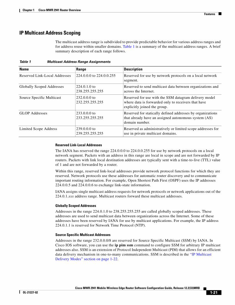
The multicast address range is subdivided to provide predictable behavior for various address ranges and for address reuse within smaller domains. Table 1 is a summary of the multicast address ranges. A brief summary description of each range follows.
Table 1 Multicast Address Range Assignments
Reserved Link-Local Addresses
The IANA has reserved the range 224.0.0.0 to 224.0.0.255 for use by network protocols on a local network segment. Packets with an address in this range are local in scope and are not forwarded by IP routers. Packets with link local destination addresses are typically sent with a time-to-live (TTL) value of 1 and are not forwarded by a router.
Within this range, reserved link-local addresses provide network protocol functions for which they are reserved. Network protocols use these addresses for automatic router discovery and to communicate important routing information. For example, Open Shortest Path First (OSPF) uses the IP addresses 224.0.0.5 and 224.0.0.6 to exchange link-state information.
IANA assigns single multicast address requests for network protocols or network applications out of the 224.0.1.xxx address range. Multicast routers forward these multicast addresses.
Globally Scoped Addresses
Addresses in the range 224.0.1.0 to 238.255.255.255 are called globally scoped addresses. These addresses are used to send multicast data between organizations across the Internet. Some of these addresses have been reserved by IANA for use by multicast applications. For example, the IP address 224.0.1.1 is reserved for Network Time Protocol (NTP).
Source Specific Multicast Addresses
Addresses in the range 232.0.0.0/8 are reserved for Source Specific Multicast (SSM) by IANA. In Cisco IOS software, you can use the ip pim ssm command to configure SSM for arbitrary IP multicast addresses also. SSM is an extension of Protocol Independent Multicast (PIM) that allows for an efficient data delivery mechanism in one-to-many communications. SSM is described in the “IP Multicast Delivery Modes” section on page 1-22.
Name Range Description
Reserved Link-Local Addresses 224.0.0.0 to 224.0.0.255 Reserved for use by network protocols on a local network segment.
Globally Scoped Addresses 224.0.1.0 to 238.255.255.255
Reserved to send multicast data between organizations and across the Internet.
Source Specific Multicast 232.0.0.0 to 232.255.255.255
Reserved for use with the SSM datagram delivery model where data is forwarded only to receivers that have explicitly joined the group.
GLOP Addresses 233.0.0.0 to 233.255.255.255
Reserved for statically defined addresses by organizations that already have an assigned autonomous system (AS) domain number.
Limited Scope Address 239.0.0.0 to 239.255.255.255
Reserved as administratively or limited scope addresses for use in private multicast domains.
1-21Cisco MWR 2941 Mobile Wireless Edge Router Software Configuration Guide, Release 12.2(33)MRB
OL-21227-02
Chapter 1 Cisco MWR 2941 Router Overview Features
GLOP Addresses
GLOP addressing (as proposed by RFC 2770, GLOP Addressing in 233/8) proposes that the 233.0.0.0/8 range be reserved for statically defined addresses by organizations that already have an AS number reserved. This practice is called GLOP addressing. The AS number of the domain is embedded into the second and third octets of the 233.0.0.0/8 address range. For example, AS 62010 is written in hexadecimal format as F23A. Separating the two octets F2 and 3A results in 242 and 58 in decimal format. These values result in a subnet of 233.242.58.0/24 that would be globally reserved for AS 62010 to use.
Limited Scope Addresses
The range 239.0.0.0 to 239.255.255.255 is reserved as administratively or limited scoped addresses for use in private multicast domains. These addresses are constrained to a local group or organization. Companies, universities, and other organizations can use limited scope addresses to have local multicast applications that will not be forwarded outside their domain. Routers typically are configured with filters to prevent multicast traffic in this address range from flowing outside an autonomous system (AS) or any user-defined domain. Within an AS or domain, the limited scope address range can be further subdivided so that local multicast boundaries can be defined.
Note Network administrators may use multicast addresses in this range, inside a domain, without conflicting with others elsewhere in the Internet.
Layer 2 Multicast Addresses
Historically, network interface cards (NICs) on a LAN segment could receive only packets destined for their burned-in MAC address or the broadcast MAC address. In IP multicast, several hosts need to be able to receive a single data stream with a common destination MAC address. Some means had to be devised so that multiple hosts could receive the same packet and still be able to differentiate between several multicast groups. One method to accomplish this is to map IP multicast Class D addresses directly to a MAC address. Using this method, NICs can receive packets destined to many different MAC address.
Cisco Group Management Protocol (CGMP) is used on routers connected to Catalyst switches to perform tasks similar to those performed by IGMP. CGMP is necessary for those Catalyst switches that cannot distinguish between IP multicast data packets and IGMP report messages, both of which are addressed to the same group address at the MAC level.
IP Multicast Delivery Modes
IP multicast delivery modes differ only for the receiver hosts, not for the source hosts. A source host sends IP multicast packets with its own IP address as the IP source address of the packet and a group address as the IP destination address of the packet.
Any Source Multicast
For the Any Source Multicast (ASM) delivery mode, an IP multicast receiver host can use any version of IGMP to join a multicast group. This group is notated as G in the routing table state notation. By joining this group, the receiver host is indicating that it wants to receive IP multicast traffic sent by any source to group G. The network will deliver IP multicast packets from any source host with the destination address G to all receiver hosts in the network that have joined group G.
1-22Cisco MWR 2941 Mobile Wireless Edge Router Software Configuration Guide, Release 12.2(33)MRB
OL-21227-02
Chapter 1 Cisco MWR 2941 Router Overview Features
ASM requires group address allocation within the network. At any given time, an ASM group should only be used by a single application. When two applications use the same ASM group simultaneously, receiver hosts of both applications will receive traffic from both application sources. This may result in unexpected excess traffic in the network. This situation may cause congestion of network links and malfunction of the application receiver hosts.
Note Release 12.2(33)MRB does not support Any Source Multicast.
Source Specific Multicast
Source Specific Multicast (SSM) is a datagram delivery model that best supports one-to-many applications, also known as broadcast applications. SSM is a core network technology for the Cisco implementation of IP multicast targeted for audio and video broadcast application environments and is described in RFC 3569. Source specific multicast consists of
• Protocol Independent Multicast source-specific mode (PIM-SSM)
• Internet Group Management Protocol Version 3 (IGMPv3)
For the SSM delivery mode, an IP multicast receiver host must use IGMP Version 3 (IGMPv3) to subscribe to channel (S,G). By subscribing to this channel, the receiver host is indicating that it wants to receive IP multicast traffic sent by source host S to group G. The network will deliver IP multicast packets from source host S to group G to all hosts in the network that have subscribed to the channel (S, G).
SSM does not require group address allocation within the network, only within each source host. Different applications running on the same source host must use different SSM groups. Different applications running on different source hosts can arbitrarily reuse SSM group addresses without causing any excess traffic on the network.
Protocol Independent Multicast
The Protocol Independent Multicast (PIM) protocol maintains the current IP multicast service mode of receiver-initiated membership. PIM is not dependent on a specific unicast routing protocol; it is IP routing protocol independent and can leverage whichever unicast routing protocols are used to populate the unicast routing table, including Open Shortest Path First (OSPF), Border Gateway Protocol (BGP), and static routes. PIM uses unicast routing information to perform the multicast forwarding function.
Although PIM is called a multicast routing protocol, it actually uses the unicast routing table to perform the reverse path forwarding (RPF) check function instead of building up a completely independent multicast routing table. Unlike other routing protocols, PIM does not send and receive routing updates between routers.
PIM is defined in RFC 2362, Protocol-Independent Multicast-Sparse Mode (PIM-SM): Protocol Specification.
1-23Cisco MWR 2941 Mobile Wireless Edge Router Software Configuration Guide, Release 12.2(33)MRB
OL-21227-02

Chapter 1 Cisco MWR 2941 Router Overview Features
PIM Modes
Cisco IOS defines the following PIM modes:
• PIM Dense Mode—Uses a push model to flood multicast traffic to every corner of the network. This push model is a method for delivering data to the receivers without the receivers requesting the data. This method is efficient in certain deployments in which there are active receivers on every subnet in the network. Dense mode is not supported in Release 12.2(33)MRB.
• PIM Sparse Mode—Uses a pull model to deliver multicast traffic. Only network segments with active receivers that have explicitly requested the data will receive the traffic. PIM sparse mode is supported in Release 12.2(33)MRB.
• Sparse-Dense Mode—PIM runs sparse and dense mode according to the group mode; the interface is treated as dense mode if the group is in dense mode; the interface is treated in sparse mode if the group is in sparse mode. Sparse-dense mode is supported in Release 12.2(33)MRB.
• Bidirectional PIM—Traffic is routed only along a bidirectional shared tree that is rooted at the RP for the group. In bidir-PIM, the IP address of the RP acts as the key to having all routers establish a loop-free spanning tree topology rooted in that IP address. Bidirectional PIM is not supported in Release 12.2(33)MRB.
For more information about PIM modes, see the Cisco IOS IP Multicast Configuration Guide, Release 12.2SR.
Multicast Group Modes
In PIM, packet traffic for a multicast group is routed according to the rules of the mode configured for that multicast group. Cisco IOS supports four modes for a multicast group:
• PIM Bidirectional mode—Traffic is routed only along a bidirectional shared tree that is rooted at the rendezvous point (RP) for the group.
• PIM Sparse mode—Uses a unidirectional shared tree whose root node is called the rendezvous point (RP).
• PIM Dense mode—Dense mode operates using the broadcast (flood) and prune model.
• PIM Source Specific Multicast (SSM) mode—Datagram traffic is forwarded to receivers from only those multicast sources that the receivers have explicitly joined.
The MWR 2941 supports PIM Sparse mode and PIM SSM mode.
Sparse Mode
Sparse mode operation centers around a single unidirectional shared tree whose root node is called the rendezvous point (RP). Sources must register with the RP to get their multicast traffic to flow down the shared tree by way of the RP. This registration process actually triggers a shortest path tree (SPT) Join by the RP toward the source when there are active receivers for the group in the network.
A sparse mode group uses the explicit join model of interaction. Receiver hosts join a group at a rendezvous point (RP). Different groups can have different RPs.
Multicast traffic packets flow down the shared tree to only those receivers that have explicitly asked to receive the traffic.
Note The Cisco MWR 2941 supports sparse mode with a single static Rendezvous Point.
1-24Cisco MWR 2941 Mobile Wireless Edge Router Software Configuration Guide, Release 12.2(33)MRB
OL-21227-02

Chapter 1 Cisco MWR 2941 Router Overview Features
For more information about sparse mode, see the Cisco IOS IP Multicast Configuration Guide, Release 12.2SR.
PIM Source Specific Multicast Mode
SSM is a datagram delivery model that best supports one-to-many applications, also known as broadcast applications. SSM is a core networking technology for the Cisco implementation of IP multicast solutions targeted for audio and video broadcast application environments and is described in RFC 3569. The following two Cisco IOS components together support the implementation of SSM:
• Protocol Independent Multicast source-specific mode (PIM-SSM)
• Internet Group Management Protocol Version 3 (IGMPv3)
Protocol Independent Multicast (PIM) SSM, or PIM-SSM, is the routing protocol that supports the implementation of SSM and is derived from PIM sparse mode (PIM-SM). IGMP is the Internet Engineering Task Force (IETF) standards track protocol used for hosts to signal multicast group membership to routers. IGMP Version 3 supports source filtering, which is required for SSM. For SSM to run with IGMPv3, SSM must be supported in the Cisco IOS router, the host where the application is running, and the application itself.
For more information about SSM, see the Cisco IOS IP Multicast Configuration Guide, Release 12.2SR.
Rendezvous Points
A rendezvous point (RP) is a role that a router performs when operating in PIM-SM mode. An RP is required only in networks running PIM-SM. In PIM-SM, only network segments with active receivers that have explicitly requested multicast data will be forwarded the traffic. This method of delivering multicast data is in contrast to the PIM dense mode (PIM-DM) model. In PIM-DM, multicast traffic is initially flooded to all segments of the network. Routers that have no downstream neighbors or directly connected receivers prune back the unwanted traffic.
An RP acts as the meeting place for sources and receivers of multicast data. In a PIM-SM network, sources must send their traffic to the RP. This traffic is then forwarded to receivers down a shared distribution tree. By default, when the first hop router of the receiver learns about the source, it will send a Join message directly to the source, creating a source-based distribution tree from the source to the receiver. This source tree does not include the RP unless the RP is located within the shortest path between the source and receiver.
In most cases, the placement of the RP in the network is not a complex decision. By default, the RP is needed only to start new sessions with sources and receivers. Consequently, the RP experiences little overhead from traffic flow or processing. In PIM version 2, the RP performs less processing than in PIM version 1 because sources must only periodically register with the RP to create state.
Auto-RP
In the first version of PIM-SM, all leaf routers (routers directly connected to sources or receivers) were required to be manually configured with the IP address of the RP. This type of configuration is also known as static RP configuration. Configuring static RPs is relatively easy in a small network, but it can be laborious in a large, complex network.
Following the introduction of PIM-SM version 1, Cisco implemented a version of PIM-SM with the Auto-RP feature. Auto-RP automates the distribution of group-to-RP mappings in a PIM network. Auto-RP has the following benefits:
• Configuring the use of multiple RPs within a network to serve different groups is easy.
1-25Cisco MWR 2941 Mobile Wireless Edge Router Software Configuration Guide, Release 12.2(33)MRB
OL-21227-02

Chapter 1 Cisco MWR 2941 Router Overview Features
• Auto-RP allows load splitting among different RPs and arrangement of RPs according to the location of group participants.
• Auto-RP avoids inconsistent, manual RP configurations that can cause connectivity problems.
Multiple RPs can be used to serve different group ranges or serve as backups to each other. For Auto-RP to work, a router must be designated as an RP-mapping agent, which receives the RP-announcement messages from the RPs and arbitrates conflicts. The RP-mapping agent then sends the consistent group-to-RP mappings to all other routers. Thus, all routers automatically discover which RP to use for the groups they support.
Note If you configure PIM in sparse mode or sparse-dense mode and do not configure Auto-RP, you must statically configure an RP.
Note If router interfaces are configured in sparse mode, Auto-RP can still be used if all routers are configured with a static RP address for the Auto-RP groups.
To make Auto-RP work, a router must be designated as an RP mapping agent, which receives the RP announcement messages from the RPs and arbitrates conflicts. The RP mapping agent then sends the consistent group-to-RP mappings to all other routers by dense mode flooding. Thus, all routers automatically discover which RP to use for the groups they support. The Internet Assigned Numbers Authority (IANA) has assigned two group addresses, 224.0.1.39 and 224.0.1.40, for Auto-RP. One advantage of Auto-RP is that any change to the RP designation must be configured only on the routers that are RPs and not on the leaf routers. Another advantage of Auto-RP is that it offers the ability to scope the RP address within a domain. Scoping can be achieved by defining the time-to-live (TTL) value allowed for the Auto-RP advertisements.
Each method for configuring an RP has its own strengths, weaknesses, and level of complexity. In conventional IP multicast network scenarios, we recommend using Auto-RP to configure RPs because it is easy to configure, well-tested, and stable. The alternative ways to configure an RP are static RP, Auto-RP, and bootstrap router.
Bootstrap Router
Another RP selection model called bootstrap router (BSR) was introduced after Auto-RP in PIM-SM version 2. BSR performs similarly to Auto-RP in that it uses candidate routers for the RP function and for relaying the RP information for a group. RP information is distributed through BSR messages, which are carried within PIM messages. PIM messages are link-local multicast messages that travel from PIM router to PIM router. Because of this single hop method of disseminating RP information, TTL scoping cannot be used with BSR. A BSR performs similarly as an RP, except that it does not run the risk of reverting to dense mode operation, and it does not offer the ability to scope within a domain.
Multicast Source Discovery Protocol
In the PIM sparse mode model, multicast sources and receivers must register with their local rendezvous point (RP). Actually, the router closest to a source or a receiver registers with the RP, but the key point to note is that the RP “knows” about all the sources and receivers for any particular group. RPs in other domains have no way of knowing about sources that are located in other domains. Multicast Source Discovery Protocol (MSDP) is an elegant way to solve this problem.
MSDP is a mechanism that allows RPs to share information about active sources. RPs know about the receivers in their local domain. When RPs in remote domains hear about the active sources, they can pass on that information to their local receivers. Multicast data can then be forwarded between the domains.
1-26Cisco MWR 2941 Mobile Wireless Edge Router Software Configuration Guide, Release 12.2(33)MRB
OL-21227-02

Chapter 1 Cisco MWR 2941 Router Overview Features
A useful feature of MSDP is that it allows each domain to maintain an independent RP that does not rely on other domains, but it does enable RPs to forward traffic between domains. PIM-SM is used to forward the traffic between the multicast domains.
The RP in each domain establishes an MSDP peering session using a TCP connection with the RPs in other domains or with border routers leading to the other domains. When the RP learns about a new multicast source within its own domain (through the normal PIM register mechanism), the RP encapsulates the first data packet in a Source-Active (SA) message and sends the SA to all MSDP peers. Each receiving peer uses a modified Reverse Path Forwarding (RPF) check to forward the SA, until the SA reaches every MSDP router in the interconnected networks—theoretically the entire multicast internet. If the receiving MSDP peer is an RP, and the RP has a (*, G) entry for the group in the SA (there is an interested receiver), the RP creates (S,G) state for the source and joins to the shortest path tree for the source. The encapsulated data is decapsulated and forwarded down the shared tree of that RP. When the last hop router (the router closest to the receiver) receives the multicast packet, it may join the shortest path tree to the source. The MSDP speaker periodically sends SAs that include all sources within the domain of the RP.
MSDP was developed for peering between Internet service providers (ISPs). ISPs did not want to rely on an RP maintained by a competing ISP to provide service to their customers. MSDP allows each ISP to have its own local RP and still forward and receive multicast traffic to the Internet.
Anycast RP
Anycast RP is a useful application of MSDP. Originally developed for interdomain multicast applications, MSDP used for Anycast RP is an intradomain feature that provides redundancy and load-sharing capabilities. Enterprise customers typically use Anycast RP for configuring a Protocol Independent Multicast sparse mode (PIM-SM) network to meet fault tolerance requirements within a single multicast domain.
In Anycast RP, two or more RPs are configured with the same IP address on loopback interfaces. The Anycast RP loopback address should be configured with a 32-bit mask, making it a host address. All the downstream routers should be configured to “know” that the Anycast RP loopback address is the IP address of their local RP. IP routing automatically will select the topologically closest RP for each source and receiver. Assuming that the sources are evenly spaced around the network, an equal number of sources will register with each RP. That is, the process of registering the sources will be shared equally by all the RPs in the network.
Because a source may register with one RP and receivers may join to a different RP, a method is needed for the RPs to exchange information about active sources. This information exchange is done with MSDP.
In Anycast RP, all the RPs are configured to be MSDP peers of each other. When a source registers with one RP, an SA message will be sent to the other RPs informing them that there is an active source for a particular multicast group. The result is that each RP will know about the active sources in the area of the other RPs. If any of the RPs were to fail, IP routing would converge and one of the RPs would become the active RP in more than one area. New sources would register with the backup RP. Receivers would join toward the new RP and connectivity would be maintained.
Note The RP is normally needed only to start new sessions with sources and receivers. The RP facilitates the shared tree so that sources and receivers can directly establish a multicast data flow. If a multicast data flow is already directly established between a source and the receiver, then an RP failure will not affect that session. Anycast RP ensures that new sessions with sources and receivers can begin at any time.
1-27Cisco MWR 2941 Mobile Wireless Edge Router Software Configuration Guide, Release 12.2(33)MRB
OL-21227-02

Chapter 1 Cisco MWR 2941 Router Overview Features
Multicast Forwarding
Forwarding of multicast traffic is accomplished by multicast-capable routers. These routers create distribution trees that control the path that IP multicast traffic takes through the network in order to deliver traffic to all receivers.
Multicast traffic flows from the source to the multicast group over a distribution tree that connects all of the sources to all of the receivers in the group. This tree may be shared by all sources (a shared tree) or a separate distribution tree can be built for each source (a source tree). The shared tree may be one-way or bidirectional.
Before describing the structure of source and shared trees, it is helpful to explain the notations that are used in multicast routing tables. These notations include the following:
• (S,G) = (unicast source for the multicast group G, multicast group G)
• (*,G) = (any source for the multicast group G, multicast group G)
The notation of (S,G), pronounced “S comma G,” enumerates a shortest path tree where S is the IP address of the source and G is the multicast group address.
Shared trees are (*,G) and the source trees are (S,G) and always routed at the sources.
Multicast Distribution Source Tree (Shortest Path Tree)
The simplest form of a multicast distribution tree is a source tree. A source tree has its root at the source host and has branches forming a spanning tree through the network to the receivers. Because this tree uses the shortest path through the network, it is also referred to as a shortest path tree (SPT).
Figure 7 shows an example of an SPT for group 224.1.1.1 rooted at the source, Host A, and connecting two receivers, Hosts B and C.
Figure 7 Source Tree
Using standard notation, the SPT for the example shown in Figure 7 would be (192.168.1.1, 224.1.1.1).
The (S,G) notation implies that a separate SPT exists for each individual source sending to each group—which is correct.
Host A
Host B Host C
Notation: (S, G)S = sourceG = group
A B
C E
D F
192.168.1.1
192.168.2.2 192.168.3.3
224.1.1.1 traffic
Source
Receiver Receiver
1219
32
1-28Cisco MWR 2941 Mobile Wireless Edge Router Software Configuration Guide, Release 12.2(33)MRB
OL-21227-02

Chapter 1 Cisco MWR 2941 Router Overview Features
Multicast Distribution Shared Tree
Unlike source trees that have their root at the source, shared trees use a single common root placed at some chosen point in the network. This shared root is called a rendezvous point (RP).
Figure 8 shows a shared tree for the group 224.2.2.2 with the root located at Router D. This shared tree is unidirectional. Source traffic is sent towards the RP on a source tree. The traffic is then forwarded down the shared tree from the RP to reach all of the receivers (unless the receiver is located between the source and the RP, in which case it will be serviced directly).
Figure 8 Shared Distribution Tree
In this example, multicast traffic from the sources, Hosts A and D, travels to the root (Router D) and then down the shared tree to the two receivers, Hosts B and C. Because all sources in the multicast group use a common shared tree, a wildcard notation written as (*, G), pronounced “star comma G,” represents the tree. In this case, * means all sources, and G represents the multicast group. Therefore, the shared tree shown in Figure 8 would be written as (*, 224.2.2.2).
Both source trees and shared trees are loop-free. Messages are replicated only where the tree branches. Members of multicast groups can join or leave at any time; therefore the distribution trees must be dynamically updated. When all the active receivers on a particular branch stop requesting the traffic for a particular multicast group, the routers prune that branch from the distribution tree and stop forwarding traffic down that branch. If one receiver on that branch becomes active and requests the multicast traffic, the router will dynamically modify the distribution tree and start forwarding traffic again.
Source Tree Advantage
Source trees have the advantage of creating the optimal path between the source and the receivers. This advantage guarantees the minimum amount of network latency for forwarding multicast traffic. However, this optimization comes at a cost. The routers must maintain path information for each source. In a network that has thousands of sources and thousands of groups, this overhead can quickly become a resource issue on the routers. Memory consumption from the size of the multicast routing table is a factor that network designers must take into consideration.
Host A
Host D
Host B Host C
Notation: (*, G)* = all sourcesG = group
A B
C E
DRendezvous
Point
F
192.168.1.1
192.168.4.4
192.168.2.2 192.168.3.3
224.2.2.2 traffic
Source 1
Source 2
Receiver Receiver
1219
33
1-29Cisco MWR 2941 Mobile Wireless Edge Router Software Configuration Guide, Release 12.2(33)MRB
OL-21227-02

Chapter 1 Cisco MWR 2941 Router Overview Features
Shared Tree Advantage
Shared trees have the advantage of requiring the minimum amount of state in each router. This advantage lowers the overall memory requirements for a network that only allows shared trees. The disadvantage of shared trees is that under certain circumstances the paths between the source and receivers might not be the optimal paths, which might introduce some latency in packet delivery. For example, in Figure 8 the shortest path between Host A (source 1) and Host B (a receiver) would be Router A and Router C. Because we are using Router D as the root for a shared tree, the traffic must traverse Routers A, B, D and then C. Network designers must carefully consider the placement of the rendezvous point (RP) when implementing a shared tree-only environment.
In unicast routing, traffic is routed through the network along a single path from the source to the destination host. A unicast router does not consider the source address; it considers only the destination address and how to forward the traffic toward that destination. The router scans through its routing table for the destination address and then forwards a single copy of the unicast packet out the correct interface in the direction of the destination.
In multicast forwarding, the source is sending traffic to an arbitrary group of hosts that are represented by a multicast group address. The multicast router must determine which direction is the upstream direction (toward the source) and which one is the downstream direction (or directions) toward the receivers. If there are multiple downstream paths, the router replicates the packet and forwards it down the appropriate downstream paths (best unicast route metric)—which is not necessarily all paths. Forwarding multicast traffic away from the source, rather than to the receiver, is called Reverse Path Forwarding (RPF). RPF is described in the following section.
Reverse Path Forwarding (RPF)
In unicast routing, traffic is routed through the network along a single path from the source to the destination host. A unicast router does not consider the source address; it considers only the destination address and how to forward the traffic toward that destination. The router scans through its routing table for the destination network and then forwards a single copy of the unicast packet out the correct interface in the direction of the destination.
In multicast forwarding, the source is sending traffic to an arbitrary group of hosts that are represented by a multicast group address. The multicast router must determine which direction is the upstream direction (toward the source) and which one is the downstream direction (or directions) toward the receivers. If there are multiple downstream paths, the router replicates the packet and forwards it down the appropriate downstream paths (best unicast route metric)—which is not necessarily all paths. Forwarding multicast traffic away from the source, rather than to the receiver, is called Reverse Path Forwarding (RPF). RPF is an algorithm used for forwarding multicast datagrams.
Protocol Independent Multicast (PIM) uses the unicast routing information to create a distribution tree along the reverse path from the receivers towards the source. The multicast routers then forward packets along the distribution tree from the source to the receivers. RPF is a key concept in multicast forwarding. It enables routers to correctly forward multicast traffic down the distribution tree. RPF makes use of the existing unicast routing table to determine the upstream and downstream neighbors. A router will forward a multicast packet only if it is received on the upstream interface. This RPF check helps to guarantee that the distribution tree will be loop-free.
1-30Cisco MWR 2941 Mobile Wireless Edge Router Software Configuration Guide, Release 12.2(33)MRB
OL-21227-02

Chapter 1 Cisco MWR 2941 Router Overview Features
RPF Check
When a multicast packet arrives at a router, the router performs an RPF check on the packet. If the RPF check succeeds, the packet is forwarded. Otherwise, it is dropped.
For traffic flowing down a source tree, the RPF check procedure works as follows:
1. The router looks up the source address in the unicast routing table to determine if the packet has arrived on the interface that is on the reverse path back to the source.
2. If the packet has arrived on the interface leading back to the source, the RPF check succeeds and the packet is forwarded out the interfaces present in the outgoing interface list of a multicast routing table entry.
3. If the RPF check in Step 2 fails, the packet is dropped.
Figure 9 shows an example of an unsuccessful RPF check.
Figure 9 RPF Check Fails
As Figure 9 illustrates, a multicast packet from source 151.10.3.21 is received on serial interface 0 (S0). A check of the unicast route table shows that S1 is the interface this router would use to forward unicast data to 151.10.3.21. Because the packet has arrived on interface S0, the packet is discarded.
Figure 10 shows an example of a successful RPF check.
Figure 10 RPF Check Succeeds
In this example, the multicast packet has arrived on interface S1. The router refers to the unicast routing table and finds that S1 is the correct interface. The RPF check passes, and the packet is forwarded.
For more information about multicast routing, see the Cisco IOS IP Multicast Configuration Guide, Release 12.2SR. For instructions on how to configure multicast routing, see the “Configuring IP Multicast” section on page 4-64.
Multicast packet fromsource 151.10.3.21
S1S0
S2
E0
Multicast Route Table
RPF Check FailsNetwork Interface
151.10.0.0/16 S1198.14.32.0/24 S0204.1.16.0/24 E0
Packet arrived onwrong interface.Discard packet.
1219
34
Multicast packet fromsource 151.10.3.21
S1S0
S2
E0
Multicast Route Table
RPF CheckSucceeds
Network Interface
151.10.0.0/16 S1198.14.32.0/24 S0204.1.16.0/24 E0
Packet arrived oncorrect interface.
1219
35
1-31Cisco MWR 2941 Mobile Wireless Edge Router Software Configuration Guide, Release 12.2(33)MRB
OL-21227-02
Chapter 1 Cisco MWR 2941 Router Overview Features
MLPPP Optimization FeaturesThe Cisco MWR 2941 supports several features that improve the performance of Multilink Point-to-Point Protocol (MLPPP) connections and related applications such as PWE3 over MLPPP and IP over MLPPP.
Distributed Multilink Point-to-Point Protocol (dMLPPP) Offload
Distributed Multilink Point-to-Point Protocol (dMLPPP) allows you to combine T1 or E1 connections into a bundle that has the combined bandwidth of all of the connections in the bundle, providing improved capacity and CPU utilization over MLPPP. The dMLPPP offload feature improves the performance for traffic in dMLPPP applications such as PWE3 over MLPPP and IP over MLPPP by shifting processing of this traffic from the main CPU to the network processor.
The Cisco MWR 2941 supports up to four serial links per T1/E1 connection and up to 24 MLPPP bundles. You can use the fixed T1/E1 ports to create up to 64 MLPPP links; if you install two four-port T1/E1 HWICs, you can create up to 96 MLPPP links.
The MWR 2941 implementation of multilink (dMLPPP) uses interleaving to allow short, delay-sensitive packets to be transmitted within a predictable amount of time. Interleaving allows the MWR 2941 to interrupt the transmission of delay-insensitive packets in order to transmit delay-sensitive packets. You can also adjust the responsiveness of the MWR 2941 to delay-sensitive traffic by adjusting the maximum fragment size; this value determines the maximum delay that a delay-sensitive packet can encounter while the MWR 2941 transmits queued fragments of delay-insensitive traffic.
Multiclass MLPPP
The MWR 2941 implementation of dMLPPP also supports Multiclass MLPPP. Multiclass MLPPP is an extension to MLPPP functionality that allows you to divide traffic passing over a multilink bundle into several independently sequenced streams or classes. Each multiclass MLPPP class has a unique sequence number, and the receiving network peer processes each stream independently. The multiclass MLPPP standard is defined in RFC 2686.
The MWR 2941 supports the following multiclass MLPPP classes:
• Class 0–Data traffic that is subject to normal MLPPP fragmentation. Appropriate for non-delay-sensitive traffic.
• Class 1–Data traffic that can be interleaved but not fragmented. Appropriate for delay-sensitive traffic such as voice.
For instructions on how to configure MLPPP backhaul, see the “Configuring MLPPP Backhaul” section on page 4-49.
Note The Cisco MWR 2941 does not support some PPP and MLPPP options when the bundle is offloaded to the network processor; you can retain these options by disabling MLPPP and IPHC offloading for a given bundle. For more information, see the “MLPPP Offload” section on page 4-58.
Note The output for the show ppp multilink command for an offloaded MLPPP bundle differs from the output for a non-offloaded bundle. For more information, see Appendix B, “Cisco MWR 2941 Router Command Reference.”
1-32Cisco MWR 2941 Mobile Wireless Edge Router Software Configuration Guide, Release 12.2(33)MRB
OL-21227-02

Chapter 1 Cisco MWR 2941 Router Overview Features
Layer 3 Virtual Private NetworksA Virtual Private Network (VPN) is an IP-based network that delivers private network services over a public infrastructure. VPNs allow you to create a set of sites that can communicate privately over the Internet or other public or private networks.
A conventional VPN consists of a full mesh of tunnels or permanent virtual circuits (PVCs) connecting all of the sites within the VPN. This type of VPN requires changes to each edge device in the VPN in order to add a new site. Layer 3 VPNs are easier to manage and expand than conventional VPNs because they use layer 3 communication protocols and are based on a peer model. The peer model enables the service provider and customer to exchange Layer 3 routing information, enabling service providers to relay data between customer sites without customer involvement. The peer model also provides improved security of data transmission between VPN sites because data is isolated between improves security between VPN sites.
The Cisco MWR 2941 supports the following MPLS VPN types:
• Basic Layer 3 VPN—Provides a VPN private tunnel connection between customer edge (CE) devices in the service provider network. The provider edge (PE) router uses Multiprotocol Border Gateway Protocol (MP-BGP) to distribute VPN routes and MPLS Label Distribution Protocol (LDP) to distribute Interior Gateway Protocol (IGP) labels to the next-hop PE router.
• MPLS Carrier Supporting Carrier (CSC) VPN—Enables an MPLS VPN-based service provider to allow other service providers to use a segment of its backbone network. MPLS CSC VPNs use MPLS LDP to distribute MPLS labels and IGP to distribute routes.
• Inter-Autonomous System (AS) VPN—An inter-AS VPN allows service providers running separate networks to jointly offer MPLS VPN services to the same end customer; an inter-AS VPN can begin at one customer site and traverse multiple service provider backbones before arriving at another customer site.
For instructions on how to configure an layer 3 VPN, see the “Layer 3 Virtual Private Networks” section on page 1-33.
Intelligent Cell Site IP ServicesThe Cisco RAN-O and IP-RAN solutions allow you to deliver profit-enhancing services. This is achieved through the set of IP networking features supported in Cisco IOS software that extends to the cell site (see Figure 1-11 on page 1-34).
Cell Site Points-of-Presence
The cell site becomes a physical Point-of-Presence (POP) from which to offer hotspot services, or voice and wired ISP services, to nearby enterprises and residences. Because many cell sites are located in and around downtown areas, hotels, airports, and convention centers, they make attractive sites for co-locating public wireless LAN (PWLAN) access points and other wireless data overlays. Many of these wireless data radios are IP-based. IP networking features, like Mobile IP, VoIP, IP Multicast, VPN, and content caching, enable delivery of new revenue-generating services over these radios. The corresponding traffic “rides for free” on the spare backhaul bandwidth made available by Cisco Abis solutions (see Figure 1-11).
1-33Cisco MWR 2941 Mobile Wireless Edge Router Software Configuration Guide, Release 12.2(33)MRB
OL-21227-02

Chapter 1 Cisco MWR 2941 Router Overview Features
Figure 1-11 Cisco MWR 2941 Router in a Cell Site POP—Example
Quality of ServiceThis section describes the Quality of Service (QoS) features on the Cisco MWR 2941. The Cisco MWR 2941 supports the following QoS features:
• Traffic Classification
• Traffic Marking
• Traffic Queuing
• Traffic Shaping
Note The Cisco MWR 2941 support for QoS varies based on the interface and traffic type. For more information about the QoS limitations, see the “Configuring Quality of Service (QoS)” section on page 4-88.
For instructions on how to configure QoS on the Cisco MWR 2941, see the “Configuring Quality of Service (QoS)” section on page 4-88.
PWLANWCDMA-TDD
WiMAX(802.16/20)
GSM BTS IP-PBX BSC
RNC
Ciscomobile
exchange
100/1000 Ethernet T1/E1/Ethernet/xDSL
Cell site Access network BSC/RNC site MobileInternet
edge
Abis/lub over IP
CiscoMWR
Mobile IP/FAVoIPContent CachingMulti VPNIP MulticastingQoSPPPDHCPRouting
ATM
IP
TDMTDM
ATM
IP
Cisco 7600Series Router
IP-PBX
2531
53
UMTS Node B(R4/R99)HSDPA
UMTS Node B(RS/R6)
1-34Cisco MWR 2941 Mobile Wireless Edge Router Software Configuration Guide, Release 12.2(33)MRB
OL-21227-02
Chapter 1 Cisco MWR 2941 Router Overview Network Management Features
Traffic Classification
Classifying network traffic allows you to organize packets into traffic classes based on whether the traffic matches specific criteria. Classifying network traffic is the foundation for enabling many QoS features on your network. For instructions on how to configure traffic classification, see the “Configuring Classification” section on page 4-95.
Traffic Marking
Marking network traffic allows you to set or modify the attributes for packets in a defined traffic class. You can use marking with traffic classification to configure variety of QoS features for your network. For instructions on how to configure traffic marking, see the “Configuring Marking” section on page 4-97.
Traffic Queuing
The Cisco MWR 2941 supports class-based WFQ (CBWFQ) for congestion management. CBWFQ extends the standard WFQ functionality to provide support for user-defined traffic classes. For CBWFQ, you define traffic classes based on match criteria such as input interface. Packets satisfying the match criteria for a class constitute the traffic for that class. For more instructions on how to configure traffic queuing, see the “Configuring Congestion Management” section on page 4-101.
Traffic Shaping
Regulating the packet flow on the network is also known as traffic shaping. Traffic shaping allows you to control the speed of traffic leaving an interface. This way, you can match the flow of the traffic to the speed of the interface receiving the packet.
The Cisco MWR 2941 supports Class-Based Traffic Shaping. Class-Based Traffic Shaping allows you to regulate the flow of packets leaving an interface on a per-traffic-class basis, matching the packet flow to the speed of the interface. For more instructions on how to configure traffic shaping, see the “Configuring Shaping” section on page 4-103.
Network Management FeaturesThis section provides an overview of the network management features for the Cisco MWR 2941. For more information about management features on the Cisco MWR 2941, see the “Monitoring and Managing the Cisco MWR 2941 Router” section on page 4-107.
Cisco Mobile Wireless Transport Manager (MWTM)You can use Cisco Mobile Wireless Transport Manager (MWTM), to monitor and manage the Cisco MWR 2941. Cisco MWTM addresses the element-management requirements of mobile operators and provides fault, configuration, and troubleshooting capability. For more information about MWTM, see http://www.cisco.com/en/US/products/ps6472/tsd_products_support_series_home.html.
1-35Cisco MWR 2941 Mobile Wireless Edge Router Software Configuration Guide, Release 12.2(33)MRB
OL-21227-02

Chapter 1 Cisco MWR 2941 Router Overview Limitations and Restrictions
Cisco Active Network Abstraction (ANA)You can also use Cisco Active Network Abstraction (ANA) to manage the Cisco MWR 2941. Cisco ANA is a powerful, next-generation network resource management solution designed with a fully distributed OSS mediation platform which abstracts the network, its topology and its capabilities from the physical elements. Its virtual nature provides customers with a strong and reliable platform for service activation, service assurance and network management. For more information about ANA, see http://www.cisco.com/en/US/products/ps6776/tsd_products_support_series_home.html.
SNMP MIB SupportTo view the current MIBs that the Cisco MWR 2941 supports, see the Release Notes for Cisco MWR 2941-DC Mobile Wireless Edge Router for Cisco IOS Release 12.4(20)MR.
For instructions on how to configure MIBs on the Cisco MWR 2941, see the “Configuring SNMP Support” section on page 4-108 and the “Enabling Remote Network Management” section on page 4-112.
Cisco Networking Services (CNS)Cisco Networking Services (CNS) is a collection of services that can provide remote configuration of Cisco IOS networking devices and remote execution of some command-line interface (CLI) commands. CNS allows a Cisco MWR 2941 deployed and powered on in the field to automatically download its configuration.
Note The Cisco MWR 2941 only supports CNS over motherboard Ethernet interfaces. Other interface types do not support CNS.
For instructions on how to configure CNS, see the “Configuring Cisco Networking Services (CNS)” section on page 4-115.
Limitations and RestrictionsThe following sections describe the limitations and restrictions that apply to the Cisco MWR 2941 router.
Hardware Limitations and RestrictionsTo view a list of supported hardware and restrictions for the Cisco MWR 2941, see the Release Notes for Cisco MWR 2941-DC Mobile Wireless Edge Router for Cisco IOS Release 12.2(33)MRB.
Caution The Cisco MWR 2941 does not support online insertion and removal (OIR) of HWIC cards. Attempts to perform OIR on a card in a powered-on router might cause damage to the card.
1-36Cisco MWR 2941 Mobile Wireless Edge Router Software Configuration Guide, Release 12.2(33)MRB
OL-21227-02

Chapter 1 Cisco MWR 2941 Router Overview Limitations and Restrictions
Software Limitations and RestrictionsFor information about software limitations and restrictions for the Cisco MWR 2941, see the Release Notes for Cisco MWR 2941-DC Mobile Wireless Edge Router for Cisco IOS Release 12.2(33)MRB.
1-37Cisco MWR 2941 Mobile Wireless Edge Router Software Configuration Guide, Release 12.2(33)MRB
OL-21227-02

Chapter 1 Cisco MWR 2941 Router Overview Limitations and Restrictions
1-38Cisco MWR 2941 Mobile Wireless Edge Router Software Configuration Guide, Release 12.2(33)MRB
OL-21227-02