Embed Size (px)
Citation preview

CIFECENTER FOR INTEGRATED FACILITY ENGINEERING
An Integrated, Virtual Design and Construction and Lean (IVL)
Method for Coordination of MEP
By
Atul Khanzode
CIFE Technical Report #TR187 February 2010
STANFORD UNIVERSITY

COPYRIGHT © 2010 BY Center for Integrated Facility Engineering
If you would like to contact the authors, please write to:
c/o CIFE, Civil and Environmental Engineering Dept., Stanford University
The Jerry Yang & Akiko Yamazaki Environment & Energy Building 473 Via Ortega, Room 292, Mail Code: 4020
Stanford, CA 94305-4020
2
An Integrated Virtual Design and Construction and Lean (IVL) Method for coordination of MEP Systems Chapter from PhD Thesis by Atul R. Khanzode
Claimed Contribution: The objective of this paper is to describe the contribution to knowledge and practice in terms of an
Integrated, Virtual Design and Construction (VDC) and Lean (hereafter referred to as IVL) method for the
coordination of Mechanical, Plumbing and Electrical (MEP) Systems in the Architecture/Engineering and
Construction (AEC) industry. MEP Systems on many of the complex construction projects account for 40‐
60% of the project value. But the method to coordinate MEP systems is still very ad hoc and organizing
project teams to coordinate MEP systems remains one of the most challenging, time consuming and
poorly understood aspects of many building projects today. The lack of a consistent, well grounded and
repeatable method for MEP coordination results in wasted effort of project team members, lack of
metrics to track progress of coordination, suboptimal results due to conflicts in the field and
inconsistent performance from one project to another. The IVL method for MEP coordination addresses
these challenges and provides a repeatable method that project teams can adopt to produce consistent
results for MEP coordination. The method describes:
1. How to create the goals and objectives for the coordination of MEP systems
2. How to organize the team to coordinate MEP systems
3. What metrics to use to track progress during the coordination of MEP systems
4. What technical logistics need to be setup to manage MEP Coordination
5. How to create a schedule for the coordination of MEP systems
6. How to operate, manage against the objectives and doing managerial interventions to track
against metrics
The IVL method for MEP coordination is based on case study research of four distinct cases where the
author observed MEP coordination. The practical significance of this research is that project teams in
AEC industry can organize MEP coordination in a much more consistent manner than before and this
research also highlights the aspects of coordination processes in general that are important in AEC
industry.

3
Introduction: Mechanical, Plumbing, Electrical and Fire Protection (MEP/FP) systems on modern day high tech
projects account for about 40 to 60% of the total project cost. The complexity of these systems has
increased over the years. At the same time the cost of materials has increased and the availability of
skilled labor to install these systems is steadily declining. Owners are demanding projects to be delivered
quicker and at lesser cost. Project teams are constantly seeking newer and better methods to address
these challenges. One of the biggest areas of improvement is the design and coordination of MEP/FP
systems. On many construction projects the coordination is still done using 2D drawings and light tables
in what is called as a Sequential Composite Overlay Process (SCOP) (Korman, Fischer and Tatum, 2003).
This method of coordination has proven to be inadequate and has led to many conflicts between
systems, lack of confidence amongst subcontractors to pre‐fabricate, rework in the field and an overall
lack of productivity installing these systems in the field. Recently Project teams are exploring the use of
Virtual Design and Construction (VDC) (Fischer and Kunz, 2004) tools like 3D‐4D and collaborative
project delivery approaches like Lean construction (Ballard and Howell, 1997) to reduce the inherent
waste in this process and bring a greater efficiency and productivity to the projects. On one of the case
study projects which implemented VDC to manage the coordination of MEP/FP systems in Northern
California and the results indicate that there are tremendous benefits to applying VDC to coordinate the
MEP/FP systems. On this project using the VDC tools for the coordination of the MEP/FP the project
team has realized the following benefits (Khanzode, Reed and Fischer, 2007):
virtually zero field conflicts between various systems
less than 0.2% rework
productivity improvement of more than 30% for the mechanical contractor
less than 2 hours per month spent on field coordination issues by the Superintendent for the General Contractor
Only two field issues related Request for Information
Zero change orders related to field conflict issues
This suggests that project teams and owners gain to benefit significantly by applying VDC tools
(specifically 3D and 4D CAD) and Lean methods to manage the MEP / FP coordination process. In my
observation of the four case studies it was clear that even though project teams had the opportunity to
use VDC tools and Lean processes for coordination, there was not a single, consistent way to perform
and organize MEP coordination. I summarize the observations from the case study in the following
section.
Case Study Summary: In order to understand the impact of the use of Lean Construction Methods and VDC tools for MEP
coordination I studied four projects that used a combination of VDC and Lean methods to perform MEP
coordination. The case studies are described in more detail in the Case Study chapter of the Thesis. The
findings from the Case studies are summarized in this section. The 4 cases I reviewed are as follows:

4
Case Study VDC used for MEP Coordination Lean Methods used for MEP Coordination
Camino Medical Office Building Yes Yes
Autodesk 1 Market Project Yes No
Stanford Medical Center No Yes
PAMF MOB No No
Table 1: Table shows the Four Case Study projects and the use of VDC and Lean Methods for the
coordination of MEP systems on the four case study projects. Study is result of analysis of each of the
possible uses of VDC and Lean and forms a complete multi‐factorial prospective study of MEP
coordination.
The reason I chose the four cases as described above is because between the four cases and the varied
use of VDC methods and Lean Construction for MEP coordination forms a multi‐factorial prospective
case study pertaining to the domain of my research which is MEP coordination. To be consistent I also
chose case studies that belong to the same domain i.e. office building construction. Three of the cases
are for healthcare medical office building and one case is for a slightly complex office and customer
gallery space.
There are multiple aspects of MEP Coordination that one can study. One of the goals of MEP
coordination is to be able to produce an efficient MEP system that can be installed in the most efficient
manner, i.e. the best outcome of the MEP coordination is to be able to have the most efficient building
process. Efficient building process can be described by the outcomes from the process of manufacturing
and installing MEP systems. The measure of how efficient the process is can be obtained by observing:
1. Amount of hours spent by each trade installing the systems and comparing this to the estimated
hours
2. The field conflicts between the various systems that had to be resolved.
3. The amount of prefabrication enabled by the process
4. The actual prefabrication by each trade contractor
5. The productivity of crew installing the systems
6. The amount of time teams spent on rework to fix problems in the system
7. The number of unnecessary or avoidable change orders
The metrics that are traditionally tracked by most General Contractors and MEP subcontractors to track
the efficiency of the building process are as follows:
Schedule Compliance: This metric compares the estimated schedule to actual schedule
completion
Change Orders: This is a measure of how efficiently coordination was done, the less the change
orders the better was the outcome of MEP coordination

5
RFI or Requests for Information during construction phase: RFIs are used to clarify un‐resolved
issues. The lesser the number of RFIs during construction the better the outcome of MEP
coordination
Rework during construction: Lesser the rework during construction better the coordination is
Field Conflicts during installation: The lesser the field conflicts the better it is since this means
coordination has resolved all the conflicts
More Prefabrication: More prefabrication leads to systems being built offsite in a controlled
factory environment and requires less skilled craft people on site so a coordination which
enables more prefabrication is better.
Hours spent by Superintendents in the Field to resolve conflicts between trade contractors: The
lesser the number of hours a superintendent has to spend in the field to resolve installation
conflicts between trade subcontractors the better the outcome of MEP coordination is.
In the four case study projects I documented the how the project teams performed the MEP
coordination process and managed it. This included the controllable factors that teams used to perform
MEP coordination. I also studied the way the project teams tracked performance during MEP
coordination and the outcomes on the project as a result of what was coordinated. The outcomes were
traditional quantitative metrics such as change orders and Requests for Information but also qualitative
metrics such as the amount of time superintendents and formen spent on site to resolve field conflicts. I
also interviewed multiple team members that directly worked on these projects. The results of my
observations are described in detail in the section below.
Impact of the use of VDC and Lean Methods on Prefabrication of MEP Systems
Based on the interviews of the jobsite teams on the four case study project I identified the gross % of
prefabrication on each of the Case study project for the Mechanical, Electrical and Plumbing Systems.
The % of Prefabrication is mapped against the use of VDC and Lean methods for the 4 case study
projects in Figure 1.

6
Figure 1: Picture shows the Actual % of Prefabrication (for Mechanical, Electrical and Plumbing) on 4
case study projects. The data suggests that when VDC methods are used for coordination the % of
Actual prefabrication is higher for Mechanical systems. The data also seems to indicate the greater the
use of VDC and Lean methods greater the % of Actual Prefabrication for MEP systems.
Use of VDC seems to create more opportunities for Prefabrication. Looking deeper into the project case
studies and through Interview of Project Superintendents and Foremen on the case study projects it was
also evident that the Actual Prefabrication also depends upon other factors such as jobsite logistics
issues such as access.
Number and Timing of Requests for Information on Case Study projects:
I also reviewed what the actual number of RFIs related to conflicts or potential conflicts between the
various MEP systems were on the case study projects and also when were these RFIs generated and
answered during the project. This data is summarized in Figure 2.

7
Figure 2: Picture shows the number and timing of Request for Information (RFIs) on 4 case study
projects. The data suggests that the use of VDC early in the Design allows teams to identify more conflict
related issues versus when VDC is not used for the MEP coordination process. The data also shows that
conflict related RFIs are not completely resolved when VDC is not used.
The data suggests that the use of VDC early in the Design allows teams to identify more conflict related
issues versus when VDC is not used for the MEP coordination process. The data also shows that conflict
related RFIs are not completely resolved when VDC is not used.
Conflicts between MEP systems in the Field:
Figure 3 shows the actual conflicts that the project teams encountered during the installation of MEP
systems. These conflicts were related to the fact that the systems occupied same physical space and
were not related to the installation method. This means that the systems were not adequately
coordinated to resolve the geometric clashes during the coordination of MEP systems.
The data suggests that when VDC is used for MEP coordination teams are able to resolve conflict related
issues but when VDC is not used the number of actual conflicts between systems goes up. The data also
suggests that impact of Lean methods without VDC is marginal in resolving conflicts between MEP
systems.

8
Figure 3: Picture shows the number of Field conflicts between the various Mechanical, Plumbing and
Electrical (MEP) systems for 4 case study projects that used a combination of VDC and Lean methods
during the MEP coordination process. The data suggests that the use of VDC results in the least field
conflicts between MEP systems.
Rework during the MEP Installation process:
Figure 4 shows the % of rework during the installation of MEP systems on the 4 case study projects. The
data suggests that when VDC is used for MEP coordination there is less rework during the installation of
MEP systems compared to when VDC is not used. The data also suggests that use of Lean methods can
reduce rework but the non use of VDC is much more significant in terms of amount of rework.
0
10
20
30
YesNo
YesNoYes
YesNo
No
Conflicts in Field on 4 Case Study Projects
Conflicts in Field
VDC Used
Lean Used

9
Figure 4: Picture shows the Percentage of Rework that had to be done for MEP systems on 4 case study
projects that used a combination of VDC and Lean methods during the MEP coordination process. The
evidence suggests that the use of VDC results in the least rework also shows that using Lean techniques
alone teams can reduce rework but not completely eliminate rework.
Time spent (in minutes per day) by Superintendents in the Field Resolving conflicts between MEP
Systems:
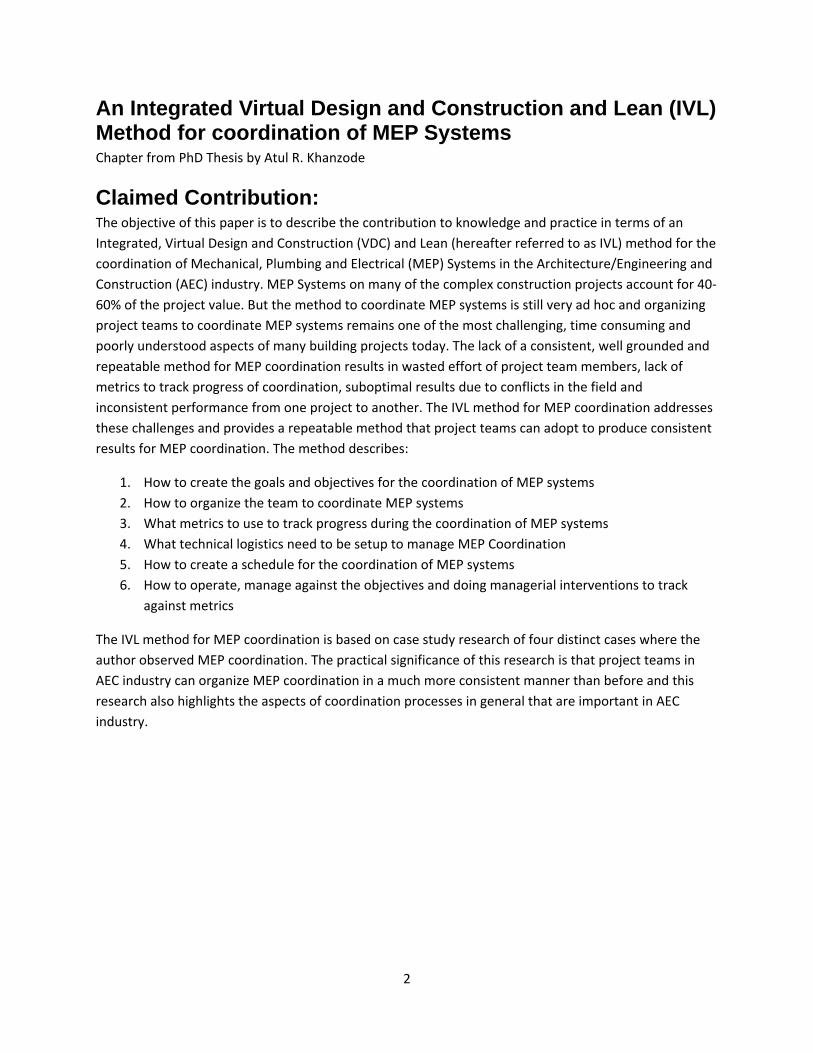
Figure 5 shows the time that the Superintendents spent (in minutes per day) in the field resolving
conflict related issues between trade subcontractors during the MEP installation process. The data
suggests that when VDC methods are used Superintendents spend less time in the field dealing with
conflict related issues compared to when VDC is not used.
Rework %
0%
5%
10%
15%
20%
YesNo
YesNo
YesYes
NoNo
Rework % on 4 Case Study Projects
Rework %
Lean Used
VDC Used
10
Figure 5: Picture shows the amount of time (in minutes) spent by the General Superintendent for the
General Contractor in the field playing referee and resolving conflicts between the MEP trades on 4 case
study projects that used a combination of VDC and Lean methods during the MEP coordination process.
The evidence suggests that the use of VDC results in the least amount of time resolving issues between
trades in the field and also suggests that the use of Lean techniques can result in better time spent in
the field although the impact of VDC seems more pronounced.
Inferences from Case Studies: What the evidence from the case studies suggests:
1. Use of VDC seems to be the key for MEP coordination process. i.e. when VDC is used the
outcome of coordination is better (more prefabrication, lesser RFIs during construction, virtually
no conflicts during construction, substantially less rework during construction, lesser the
number of conflict related change orders and less the amount of time spent by superintendents
to resolve trade conflicts during construction) but when VDC is not used the outcomes of MEP
coordination process get negatively impacted (more conflicts, more rework, more and later RFIs,
lesser prefabrication, more number of conflict related change orders and more time spent by
superintendents resolving the issues between trades in the field during construction). Upon
further studying the use of VDC on these four case study projects it was also clear than when
VDC was used it was used by a cross‐disciplinary team of designers, GC and subcontractors and
the team identified the specific trade input during the use of VDC as one of the key benefits of
using VDC for MEP coordination. This observation is critical since this substantiates the claims of
other researchers in the industry who have studied the benefits of early involvement of
specialty contractors on the project outcomes (Liker et.al., 1996)
2. Early involvement of subs seems to be the key in MEP coordination process. On the two case
study projects when the subs were involved in the coordination process earlier (during
0
100
200
Yes No Yes NoYes Yes No No
Minutes Spent per day
Hours per Day Spent by Superintendent Resolving Issues
(Minutes)
Hours per Day Spent by Superintendent Resolving Issues (Minutes)

11
schematic design) the outcome of MEP coordination was better. This also confirms the benefits
of early involvement by specialty trade contractors during the design process as observed by
others in the industry. (Gil et. al., 2000)
3. Use of VDC can lead to more prefabrication and schedule acceleration due to parallel offsite
work. Comparing the actual prefabrication that happened on the Camino MOB project as well as
discussing the prefabrication that was enabled through the coordination process with the trade
foremen it is clear that use of VDC is a necessary condition for more prefabrication and a way to
accelerate onsite installation schedule since prefabrication activities can be undertaken at
offsite facilities in parallel. The foremen also acknowledged that the decision to prefabrication
also depends heavily on the jobsite logistics. For example although the team at Autodesk 1
Market felt that they could prefabricate quite a lot more the limitation of brining the materials
in to the site meant that the prefabrication was less. On the flip side when VDC was not used the
foremen did not feel comfortable with getting prefabricated materials due to lack of certainty
that it will fit in the field although the jobsite logistics would have allowed for more
prefabrication.
4. Use of Lean seems to impact the most in terms of avoiding rework during construction process.
Compared to all other outcomes of coordination rework seems to be most impacted through
the use of Lean Last Planner method during coordination.
5. Use of Lean methods, more specifically the Pull Planning and Last Planner system adds more
reliability to the coordination of MEP systems. The Pull planning was considered important by
the project teams to align the rate at which coordination was done as well as doing coordination
based on the way the construction process was structured. Specifically the work breakdown
structure for coordination needs to match that of construction process for the process to be
most efficient. The use of Last Planner method also added more reliability to the team
commitments and when this was not done the commitment reliability was considered lower.
6. When the team members who performed coordination using VDC tools as compared to light
table coordination were also the ones who were involved in construction the outcome of MEP
coordination was better. This indicates that the use of VDC tools allows the team members a
better simulation environment to try and test solutions and also enhances their knowledge of
how the systems can be assembled in the field. This is an important point and confirms
observations made by others about the notion of practice using simulation tools leads to better
prototypes and better outcomes (Schrage, Michael, 2000).
7. Collocation seems to have an impact on the coordination process due to the early resolution of
issues. Out of the 4 case study projects one team had a fully collocated coordination, one other
team had collocated partially and two other teams had weekly work sessions for coordination.
The outcome of the collocated team in terms of MEP coordination was the best. On further
observation it was also clear that having the multi‐disciplinary team collocate was what was

12
important. This highlights the importance of collocation and also confirms the observations
made by others about collocated teams (Chachere et. al., 2004 and Liker et. al. 2000). A more
recent observation or collocated teams and outcomes to coordinate drywall construction in the
construction coordination process also points to the benefits of collocating teams in Big Rooms
to resolve coordination issues (Mikati et.al. 2007).
8. Most of the team members I interviewed agreed with the outcome metrics I have described
above but only a few explicitly tracked this during the coordination process. They also agreed
that if one has to look at the efficiency of construction then using some of these metrics to track
performance would be beneficial. Review of the four cases also showed that the tracking and
understanding of these metrics was also different amongst the different project participants.
9. Team members that I interviewed who participated in the MEP coordination process also
acknowledged that the MEP coordination process was different from project to project and that
it varied depending on the project team, general contractor they worked with and that there
was a lack of consistency between the various projects they had previously worked on and also
acknowledged that they sometimes felt helpless to influence the direction either because of the
role they were slotted for did not allow it or they did not consider it being part of their job but
someone else's job, mostly the General Contractors job. They also acknowledged that many
times the coordination process began with the sole aim of resolving the conflicts to the greatest
extent possible but the projects did not have a strategic goal or specific objectives in terms of
change orders, prefabrication etc. which they acknowledged were important factors that should
be looked at to measure the outcome of coordination.
The Integrated, Virtual Design and Construction and Lean (IVL) MEP Coordination Method:
Based on the inferences above from the four cases it is clear that a consistent, repeatable and well
understood method for MEP coordination that is based on tracking metrics during the coordination,
involves multi‐disciplinary team in coordination and uses VDC tools and Lean methods to perform
coordination is required if the industry has to see a consistent outcome from the MEP coordination
phase of the project.
To address the challenges found in the test cases the specific components of the IVL method are as
follows:
1. Strategic goals and specific objectives for the coordination of MEP systems
2. A multi‐disciplinary team to coordinate MEP systems
3. Specific performance metrics to track progress during the coordination of MEP systems and
outcome metrics to measure outcomes
4. Technical Logistics to manage MEP coordination

13
5. Pull Schedule for the coordination of MEP systems
6. Operating and managing MEP coordination against the objectives, making adjustments and
measuring outcomes and results
I propose the Integrated Virtual Design and Construction and Lean (IVL) method for coordination of MEP
systems. The IVL Method is illustrated in the Figure 6.
Figure 6: Figure illustrates the Step by Step Integrated Virtual Design and Construction and Lean (IVL)
Method MEP Coordination Method starting in the clockwise direction in the Top right hand corner of
the Mind Map. Each of the steps in described in more detail in this section.

14
Step 1: Create Strategic Goals and Specific Objectives for the coordination of MEP systems. The team needs to identify strategic objectives for the coordination process. The strategic objectives
play the role of setting the overall vision for developing specific goals, objectives and metrics for the
MEP coordination on the project. Strategic objectives can be as broad as no field conflicts, maximize
prefabrication but can involve organization factors such as time to answer questions (latency) etc. The
doers should participate in developing these strategic goals and specific objectives based on these goals.
Step 2: Organize Multi-disciplinary Team to coordinate MEP systems. This involves organizing the team of designers, general contractor and trade subcontractors that will
eventually perform coordination. The team members need to be the doers who will play a specific role
in the coordination process, should be available for the duration of the project and should be involved
continuously in the process from conceptual / schematic design all the way to finish of construction.
Under this step the specific roles of Owner, Designers, General Contractor and Specialty MEP Trade
Subcontractors should be explicitly identified.
An example is given below:
Role of the General Contractor The General Contractor (GC) enables the VDC process by acting as facilitator rather than author of the
drawings. The GC enables and coordinates the hand‐off of information from the Architects and
Engineers (A/E’s) to the subcontractors as well as the modeling and coordination work itself.
The GC’s role in initial modeling and coordination is much the same as on the project as a whole:
developing a workable pull schedule for coordination together with the design team and subcontractors
to support the construction schedule. Once the schedule is established, the GC’s Project Engineer
assigned to MEP coordination works together with the detailers to achieve sign‐off milestones using the
Last Planner System™. (Ballard, 1994)
Role of the Specialty Contractors The specialty contractors are responsible to model their portion of work using VDC tools. Typically the
HVAC Contractor takes a lead role in the coordination process. The HVAC Contractor models the main
medium pressure and low pressure duct lines and shafts so that other trades can coordinate and route
their utilities around these duct lines. The specialty contractors are also involved early in the process so
that they can provide input into the constructability and operations issues to the design team. Some
contracting methods that allow for early involvement of specialty contractors include the Design‐Assist
or Design‐Build or Integrated Project Delivery contracting methods. In these methods the specialty
contractors are brought in early (somewhere between the conceptual and schematic design phases). In
the Design‐Build method the specialty contractor is also the engineer of record for the MEP systems
while in the Design‐Assist method this responsibility may rest with an independent or third party
engineering and design firm.

15
Step 3: Develop specific performance metrics to track progress during the coordination of MEP systems and outcome metrics to measure outcomes Based on the observation from the 4 case studies and the inference from case studies the following
metrics should be tracked by the teams to manage the performance of MEP coordination.
Metric How Frequently Who Tracks the metric
Players Collaborating on Metric
Planned Percent Complete
Weekly General Contractor
Owner, Designers, Subs
Pull Schedule Milestone Compliance
At planned Pull schedule milestone date - Review weekly
General Contractor
Owner, Designers, Subs
Clashes Identified to Resolved Ratio
Weekly General Contractor
Owners, Designers, Subs
Signoff date for coordination area
At the planned coordination signoff date - Review Weekly
General Contractor
Designers, Subs
% Prefab Enabled After Signoff of each area
GC / MEP Subs
Subs, GC
Team participation Weekly All Team members
Owners, Designers, Subs / GC
Latency Daily All Team members (Informal)
Designers, Subs, GC
Cost / Production Estimate at beginning and end of coordination
At end of signoff for an area
All Team members
Table 2: Table shows the Performance Metrics for VDC Lean Method for MEP coordination.
These metrics should be:
1. Explicit and Transparent to the whole team and should be posted prominently where everyone
can see them being tracked on the project
2. Used to make changes in the behavior of team members. For example if team participation is
low then the metric should be used to improve this.
In addition to the Performance metrics the following metrics should be tracked to measure the outcome
of coordination process.
Metric How Frequently
Who Tracks the Metric
Players Collaborating on Metric
16
% Actual Prefab Weekly MEP Trade Foremen
GC / Subs
Productivity compared to Estimate
Monthly MEP Trade PM's and GC
GC / Subs
Actual RFIs related to field issues
Weekly General Contractor
GC / Subs / Desginers
Change orders related to field issues
Weekly General Contractor
GC / Subs
Hours spent in field to resolve issues
Daily General Contractor
GC / Subs Foremen
Planned versus Actual Deliveries
Daily General Contractor, MEP Trade Foremen
GC / Subs
Planned Percent complete
Weekly General Contractor
Subs / Designers / Owners
Milestones met Weekly General Contractor
All
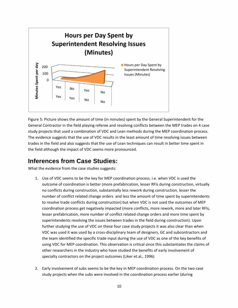
Table 3: Table shows the Outcome Metrics that Project Teams should track under the VDC Lean MEP
Coordination Method.
Step 4: Develop Technical Logistics to manage MEP Coordination.
Technical Logistics can be broken down into two things:
1. Modeling applications that support the goals for coordination and work with the fabrication
process for the specific trade contractors
2. Technical Infrastructure necessary to create the same version of reality in terms of architectural,
structural, mechanical, electrical, plumbing and fire protection models.
The issue of Technical Logistics should be answered before any coordination begins. The issues team
members should specifically address should be:
1. Resolving Interoperability between software applications to be used by various team members
during coordination
2. Developing criteria for details to be included in the model to support identified Prefabrication
objectives.
3. Agreeing on the specific process mechanisms to merge the models and create a combined MEP
model
4. Agreeing on the collaboration system and process for model collaboration
The outcome teams should thrive for is that the various team members should:

17
See the same version of model reality
Models should enable fabrication and also the approval of permit documents
An example of Technical Logistics is provided below:
The coordination of MEP / FP systems using VDC tools requires that project teams plan to create 3D
models for:
Architectural elements like interior walls, ceilings
Structural elements like the main structural framing, slabs and foundations
Mechanical systems like duct work etc.
Plumbing systems like the gravity lines, hot and cold water piping
Electrical systems like the major conduits and cable trays
Fire protection systems with the mains and branches
Other specialty systems like medical gases or other depending on the project
A summary of the various models involved in the MEP coordination process is described below followed
by a table that documents what benefits are possible for the corresponding level of details in a
particular model.
Architectural Model Architectural model forms the basis of design and is used by the team members as a reference point for
their own systems. Ideally the architect should design in 3D, rather than modeling 2D design drawings in
3D. If the 3D model is created from the 2D design documents, it is critical that it be kept up to date, i.e.,
that it reflect changes in design.
Wall thickness and height, hard ceilings and soffits, and suspended acoustical ceilings, casework with
correct fixture locations must be accurately modeled because these are necessary for effective
coordination of MEP/FP systems. On the Camino Medical Office Building (MOB) project the architect
modeled the external wall panels, internal walls, doors, and the parking garage in 3D (figure 8).
Modeling these systems in 3D is a must as it allows the other team members to accurately locate their
own systems. For example the interior wall and ceiling model allows the HVAC subcontractor to locate
the diffusers in the rooms and allows the electrical contractor to locate fixtures in the room accurately.

18
Figure 8: Figure shows an isometric view of the Camino Medical Office Building (MOB) project. The
snapshot shows a three story MOB and a two story parking structure. This 3D formed the basis of the
MEP / FP coordination for the Camino MOB project.
Structural Model An accurate 3D model of the foundation system and vertical and horizontal structural steel framing is
also a must for the MEP / FP contractors. If it is a steel framed building the model should also include
some of the connections like gusset plates and brace frame connections. The structural model should
also include the miscellaneous metal supports and connection points to external building elements like
GFRC panels. All these details play a very crucial role in the modeling of MEP / FP systems. For example
the underground plumbing lines and electrical conduits are located in reference to the foundations; the
seismic bracing for the ductwork and other systems is located in reference to the structural elements
like slabs and steel beam and columns. Figure 9 shows a structural steel and foundation model of the
Camino MOB that was created by the structural designer for the project.
As with the architectural 3D model, the structural model must accurately reflect design changes at all
times because detailing of the MEP / FP systems will be done in reference to the structural steel
framing.
If the design and coordination of MEP / FP systems begins before a steel fabricator is on board then the
steel model from the structural designer should be used as a starting point for the modeling of MEP / FP
systems. Ideally the systems should also be checked against the fabrication level structural 3D model.
The General Contractor should request that the structural steel fabricator include a detailed 3D
fabrication model in their price. The steel fabricator must agree to make this model available to the
detailing team just as soon as it has been reviewed and approved for fabrication. This fabrication model
will show all connections and be much closer to what will be installed in the field than the Structural
Engineer’s model. The steel fabrication model should be imported into the clash detection software that
the teams are using so that clash detection can be made against it before MEP fabrication commences.

19
Figure9: Figure shows a screenshot of the structural 3D model for the Camino MOB. The screenshot
shows the beams, columns, brace frame connections and foundation elements like grade beams &
spread footings for the Camino MOB. This model formed the basis of the underground and the above
ceiling MEP / FP coordination for the Camino MOB project.
Mechanical Model One of the main goals of the mechanical contractor is to be able to use their model for the pre‐
fabrication of duct and piping assemblies and also use it to plan activities like installing inserts. Currently
major mechanical subcontractors already have the capability to produce a 3D model of their systems
but are hampered in their prefabrication efforts as they do not have the confidence that their systems
will be clash free in the field because other trades only produce their designs in 2D. In a VDC enabled 3D
MEP / FP coordination process all the subcontractors need to produce their designs as 3D models. This
allows the mechanical contractor to have more confidence that the assemblies will fit as they have
coordinated with other trades and their 3D models. The mechanical model consists of the HVAC duct,
the connections between ducts, hangers and inserts, seismic supports, diffusers, VAV boxes, Fire Smoke
Dampers (FSD’s), shafts, duct and pipe insulation and the heating hot water piping. The duct and piping
models are then used for prefabrication. The hangers, inserts and seismic support model are used to
install inserts and hangers. These 3D models also allow other trades to coordinate effectively with the
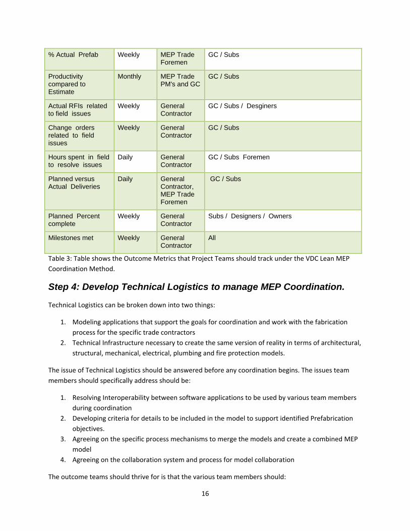
mechanical systems. For example figure 10 shows a snapshot from the mechanical model of the Camino
20
MOB project and shows the medium pressure duct, low pressure duct, the hangers and inserts and the
heating hot water piping.
Figure 10: Figure shows a snapshot of the mechanical system (HVAC duct, VAV boxes and Heating hot
water pipe) of the first floor SE quadrant of the Camino MOB project. The medium and low pressure
duct (shown in blue) and the heating hot water piping (shown in purple) allows other trades to
determine the location of the mechanical systems in 3D and use it to route and coordinate their
systems.
Electrical Model On most projects the electrical systems typically do not occupy a lot of above ceiling space and also have
some flexibility in terms of how the routing due to the use of flexible cable and wiring. Although this can
be an argument for not creating a 3D model of electrical systems it should be understood that electrical
subcontractors do use rigid conduits, cable trays, junction boxes, panels etc that do need to be
coordinated with other systems. To enable this the electrical contractor should model the branch and
feeder conduits, all underground conduits, junction boxes, all lighting, all lighting supports for specialty
lighting, all the cable trays and other supports, bundles of cables or wiring and the outlets. This allows
the team to coordinate with the electrical systems and also for the electrical contractor to pre‐fabricate
and pre‐bend most of the conduits that need to be bent and also allows them to pre‐cut cables and
wires to length required. It also allows them to create assemblies in the shop rather than the field. For
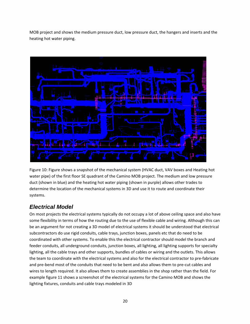
example figure 11 shows a screenshot of the electrical systems for the Camino MOB and shows the
lighting fixtures, conduits and cable trays modeled in 3D

21
Figure 11: Figure shows a snapshot of the electrical model for the first floor SE quadrant of the Camino
MOB project. The snapshot shows a 3D view of all the lighting fixtures, junction boxes, cable trays and
major conduit runs for this quadrant on the Camino MOB project.
Plumbing Model There are two major plumbing systems on most construction projects. Gravity based systems to carry
the wastewater and pressure based systems to carry hot and cold water. In addition specialty systems
like medical gases in hospitals are also part of the plumbing system. The challenge with the gravity
systems is that the systems should satisfy the slope requirements for the wastewater to flow from one
end to another. This requires the plumbing contractor to have relatively uninterrupted sloped gravity
lines and is a major challenge in the coordination effort. As with the mechanical contractor, the
plumbing contractor’s objectives are also to pre‐fabricate the plumbing assemblies and determine the
location of inserts and hangers using the 3D model. What this means is plumbing systems on most major
projects contractor should model all their plumbing fixtures, graded cast iron pipe lines, underground
storm and sewer pipes, all major waste and vent lines, cold and hot water piping, seismic details, all
boiler and other equipment and specialty piping (like medical gas piping) and specialty equipment. This
allows them to pre‐fabricate their materials in the shop environment. For example figure 12 shows a
screenshot of the 3D model with the plumbing gravity lines, fixtures, hot and cold water pipes for the
first floor SE quadrant of the Camino MOB project.

22
Figure 12: Figure shows a snapshot of the plumbing model of the first floor SE quadrant of the Camino
MOB. The snapshot shows the waste and vents and the plumbing fixture locations (in green), the cold
water supply (in blue) and hot water lines (in red).
Sprinkler Model The fire protection contractor should model the mains and branches, the drop pipes and the exact
location of drops in the ceiling. This allows them to lay out the mains and branches, prefabricate and
also install inserts before the deck is poured. For example the figure 13 shows a snapshot of the 3D
sprinkler model for one of the quadrants of the Camino MOB and shows the mains, branches and
sprinkler drops.

23
Figure 13: Figure shows a snapshot of the 3D sprinkler model of the first floor SE quadrant of the Camino
MOB. The screenshot shows the mains and branches and the sprinkler drops for the first floor quadrant
on the Camino MOB.
Level of details in the Architectural, Structural and the MEP / FP models and potential benefits One of the key questions when applying VDC methodologies to the 3D MEP / FP coordination process is
what level of detail should be included in the model and what benefits a team can get out of it. In the
following table we summarize this information:
Model Level of Detail Benefit in MEP Coordination Process
Architectural Model Wall thickness and height
Required for routing main utilities, locating VAV boxes, identifying priority wall framing, wall penetrations, fire stopping
Hard ceilings and soffits
Required for identifying HVAC diffuser locations, electrical fixture locations, routing of utilities
Suspended acoustical ceilings
Required for identifying HVAC diffuser locations, electrical fixture locations, routing of utilities

24
Casework with correct fixture locations
Useful for identifying the location of plumbing utilities rough‐in in the walls
Exterior wall / storefront
Useful for identifying the locations of rain water leaders
Shafts, Wall chases Required for identifying the correct locations of plumbing vents, HVAC shafts
Structural Model Foundations, grade beams
Required for coordination of underground utilities like electrical, plumbing
Beams and Columns Required for coordinating above ceiling MEP / FP utilities
Braces and gusset plates
Required for coordination the routing of MEP / FP piping
Miscellaneous support steel like exam light supports for medical facilities or Unistrut etc.
Required for the routing of MEP / FP utilities correctly
External wall framing connections (like connection between steel and GFRC panels)
Required to coordinate the plumbing rain water leaders
Mechanical Model Medium pressure duct
Required for coordination and routing of other trades as well as pre‐fabrication
Low pressure duct Required for coordination and routing of other trades as well as pre‐fabrication
Shaft locations Required for coordination and routing of other trades and for locating smoke dampers etc.
VAV boxes Required for pre‐fabrication purposes, coordination with HVAC heating hot water piping
Fire Smoke Dampers Useful for coordination, especially if walls are also provided in the model
Flex ducts Useful for showing how low pressure duct connects to the diffusers
Diffuser locations Useful for coordination of finish utilities with the other fixtures in a room (like electrical fixtures etc.)
Hangers and seismic bracing
Required for coordination and routing of other trades and for inserting the deck correctly before installation begins
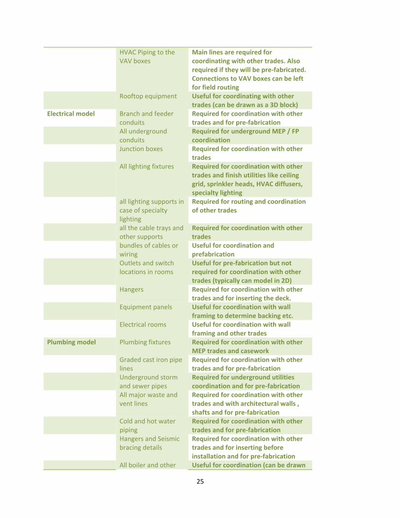
25
HVAC Piping to the VAV boxes
Main lines are required for coordinating with other trades. Also required if they will be pre‐fabricated. Connections to VAV boxes can be left for field routing
Rooftop equipment Useful for coordinating with other trades (can be drawn as a 3D block)
Electrical model Branch and feeder conduits
Required for coordination with other trades and for pre‐fabrication
All underground conduits
Required for underground MEP / FP coordination
Junction boxes Required for coordination with other trades
All lighting fixtures Required for coordination with other trades and finish utilities like ceiling grid, sprinkler heads, HVAC diffusers, specialty lighting
all lighting supports in case of specialty lighting
Required for routing and coordination of other trades
all the cable trays and other supports
Required for coordination with other trades
bundles of cables or wiring
Useful for coordination and prefabrication
Outlets and switch locations in rooms
Useful for pre‐fabrication but not required for coordination with other trades (typically can model in 2D)
Hangers Required for coordination with other trades and for inserting the deck.
Equipment panels Useful for coordination with wall framing to determine backing etc.
Electrical rooms Useful for coordination with wall framing and other trades
Plumbing model Plumbing fixtures Required for coordination with other MEP trades and casework
Graded cast iron pipe lines
Required for coordination with other trades and for pre‐fabrication
Underground storm and sewer pipes
Required for underground utilities coordination and for pre‐fabrication
All major waste and vent lines
Required for coordination with other trades and with architectural walls , shafts and for pre‐fabrication
Cold and hot water piping
Required for coordination with other trades and for pre‐fabrication
Hangers and Seismic bracing details
Required for coordination with other trades and for inserting before installation and for pre‐fabrication
All boiler and other Useful for coordination (can be drawn

26
equipment as a 3D block) Specialty piping (like
Medical Gas piping) and specialty equipment
Required for coordination with other trades and for pre‐fabrication
Sprinkler model Sprinkler mains and branches
Required for coordination with other trades and for pre‐fabrication
Sprinkler head drops Useful for coordination with finish utilities like electrical lighting, diffusers etc
Smaller sprinkler pipe Required if hard pipe is used, useful if the newer type of flex pipe is used
Table 4: Levels of Details in the various models needs to be addressed as part of the Technical Logistics.
As the table above indicates there is definitely a tradeoff between the level of details in the model and
the benefits it provides in the coordination process and the teams should identify what benefits they
want out of the modeling and coordination process before deciding what level of details the models
should include.
Other Technical Issues to address: The other issues that the project team should address include the following:
Drawings are accompanied by standard word document describing revisions therein
Drawings are posted to a project website, ftp site or a document collaboration site determined by the team which includes the GC, subs, owner and A/E team
The collaboration site provides a secure and remote access to all the drawing files
A clear file path structure is setup on the server to organize the drawing files.
Everyone works from and posts to the same server
The server is backed up every night
Borders and title blocks are not transmitted with the drawings
Use only standard AutoCAD fonts in model space. Do not use True type fonts or custom AutoCAD fonts.
Insertion point for all drawings are based on the 0,0,0 insertion point established in the architectural drawings.
For all AutoCAD based models each trade will use the EXTERNAL REFERENCE (Xref) command to bring any drawing needed into the “background”
Xref’s are not be bound or inserted
All Xref’s are detached prior to transferring drawings to other trades
Nothing is drawn in paper space
No trades draw anything on layer zero (0) or Defpoints
Anything not intended to be seen in the drawing is erased prior to file transfer
Drawings are purged (AutoCAD purge command) and audited (AutoCAD audit command) prior to file transfer to get rid of any errors or garbage in the drawing file
Text is on different layers from the graphics so the text can be turned off without turning off the graphic
Any thick lines to designate wall fire ratings are on separate layers

27
All layers are on and thawed All entities are delivered with colors, line types and line weights set to bylayer in an AutoCAD
environment.
Step 5: Develop a Pull Schedule for the coordination of MEP systems
To ensure minimum waste in the process the work breakdown structure of the coordination process
needs to match and follow the WBS of the construction. The sequence of coordination should match the
sequence of construction or enough buffer (in terms of time) needs to be created if this is not the case.
An example of the Design coordination Pull Schedule is shown below from one of the Case study
projects (Camino MOB)

28
Figure 7: Figure shows the sequence of construction and Pull schedule milestone dates for the
coordination of MEP systems for Camino MOB. The dates for coordination complete and the sequence
of coordination are pulled from the construction sequence.
The pulling of coordination from construction allows the multi‐disciplinary team to make adjustments
on what the specific needs are for what is needed during construction and adjust accordingly as
subsequent areas are coordinated.
Step 6: Operate and manage MEP coordination against the objectives, make adjustments and measure outcomes and results This step involves the coordination using VDC methods such as clash coordination and also adjusting the
process to make changes in order to accomplish the objectives of the coordination as identified in Step 1
and using metrics mentioned above.
An example of the use of VDC tools is shown below:
Using 3D Clash Detection tools to identify and resolve conflicts There are commercial tools available that allow project teams to bring in models from multiple CAD
systems into a single model and determine if two or more systems conflict with each other. One such
tool is Navisworks which has a Clash Detection program that allows teams to automatically analyze the
models for conflicts between systems. This tool was used on the Camino MOB project.

29
Conflict identification and resolution is an iterative process. The models are first combined into a single
model and then the clash detection program is run to identify clashes between systems. The clashes are
then resolved in their native programs and the iteration is performed until all clashes are resolved.
Figure 14: Clash between duct and sprinkler pipe (highlighted in red) on the Camino MOB. These clashes
were identified by the Navisworks clash detection program. In a subsequent clash resolution session
these clashes were resolved.
Figure15: The snapshot shows the resolution of the clash between duct and sprinkler pipe identified in
the previous figure has now been resolved by moving the sprinkler pipe out of the way.

30
The 4D schedule should be reviewed and status of each activity should be noted in the field foremen’s
weekly coordination meeting.
Figure 16: Foremen meeting on the Camino MOB project to discuss the construction sequence with the
aid of 2D drawings and 3D / 4D models
Figure 17: A snapshot of the 4D model from the Camino MOB project. The snapshot shows that the
inserts (little dots in the screenshot) have been installed and construction of the full height wall framing
(in green) is going on.

31
Figure 18: A snapshot of the 4D model from the Camino MOB project. The snapshot shows that the
construction of the full height wall framing (in orange) is completed and the medium pressure duct (in
green) is being installed.
One the MEP systems are installed the teams can track outcome metrics identified above for the whole
construction process. The outcome metrics can be similar to what has been identified in Figure 1 in
terms of amount of actual prefabrication, latency, schedule compliance etc.
Validation: An ideal method to validate that the IVL Method for MEP coordination leads to better results would be
to apply different versions of the method on similar construction projects and then recording and
comparing the process and outcome results. Due to the long time to conduct such a multi‐project
prospective study, we first validated the method by first doing an Internal Validation study and
comparing the elements described in the method and how well they address issues identified in the four
cases as well as parallel approaches in theories and other research that substantiate the elements of the
method. This paper describes the internal validation done on the observed test cases reported in Table
1. Subsequently, we propose to do an external validation using a charrette method with a team of
experts working in the industry providing feedback in a charrette workshop on this method for MEP
Coordination.
Internal Validation:
The first step is to identify how the method addresses the observed problems in the four case studies. I
also compared the specific elements of the method to related examples from the case studies as well as
studies and research that substantiate the elements in the method although it might not have been
done specifically for MEP coordination process.

32
The following table identified the issues or observed problems from case studies and how the various
elements of the method addresses these issues as well as related theory and research that substantiates
the elements of the method.
Examples of Issues from Case Study
Elements of the Method
What it does / Impact on Performance Metrics
Observations from Test Cases / Related Theory
Lack of strategic objective on projects about MEP Coordination
Multi‐disciplinary team developing strategic objectives related to metrics, amount of prefabrication
Strategic Direction to the coordination process
UCSF Mission Bay example of CIFE workshop and subsequent feedback on its importance
Buy‐in from everyone into common goals
Multi‐disciplinary team organized in clusters that co‐develops charters, metrics for the process
Buy‐in to the specific metrics by everyone since they participate in it
ICE Method (Chachere, et.al, 2004)
Late involvement of trade foremen into the process leads to changes downstream
Early involvement of all stakeholders in multi‐disciplinary team before coordination begins
Brings constructability knowledge upfront during coordination
Trade contractors in Design (Gil et.al, 2000)
Big batch coordination with loose tie to construction schedule leads to lack of feedback on process and needs of construction
Develop WBS and sequence of coordination schedule that matches the construction sequence
Smaller batches reduce inventory and also provide quicker feedback into the process from the needs of construction
Lean Work Structuring (Ballard, 2000) Rapid Prototyping
Technical Infrastructure does not allow teams to get on the same page
Compatible software programs and collaboration platforms that allow people to deal with the same version of reality
More time spent analyzing and deciding rather than searching for correct information
DEEPAND Framework (Christina‐Garcia, Kunz et. al. ), one of the 7 elements of ICE Framework from NASA (Chachere et. al, 2004)
Lack of understanding of process as well as outcome metrics and lack of buy‐in in tracking these metrics
Performance metrics and outcome metrics co‐created and designed to measure and adjust performance from objective of an efficient build process for MEP systems
Allows teams to make rational course correction due to tracking of metrics which are transparent and visible to everyone. Plan do Check Act
Plan Do Check Act (Deming, LCI)
Distributed teams leads to less productive coordination
Coordination in a collocated Big Room using Virtual Design and Construction Methods (3D Clash Detection, 4D
Rapid feedback, reduced latency in decision making
Integrated Concurrent Engineering (Chachere et.al, 2004) Obeya (Toyota Production System,

33
sequencing) Mikati et.al, 2007) VDC (Fischer and Kunz), MEP Coordiantion (Staub‐French et.al, 2007), (Korman, et.al, 2003)
Transparency of objectives and metrics lacking
Transparency of objectives, metrics, and virtual building process
Collective understanding of where teams are, trust due to transparency
High Performance Teams (Katzenbach, 2006)
[Detailed Description of each of the method element and related research]
Conclusion: The contribution of this research is the development of the six step VDC Lean Method for MEP
Coordination. As outlined above the VDC Lean Method for Coordination allows:
1. A consistent, repeatable method that project teams can follow to perform MEP coordination.
2. Results in better outcome of MEP coordination in terms of better MEP construction process
3. Brings together the Product, Organization and Process factors that are important for
coordination processes
4. Presents performance and outcome metrics that project teams can use to manage the
coordination process.
References:
Ballard, Glenn (2000). “Lean Project Delivery System.” White Paper 8, Lean Construction Institute
Chachere, John, Kunz, John and Levitt, Raymond, 2004," Observation, Theory and Simulation of
Integrated Concurrent Engineering: Grounded Theoretical Factors that enable Rapid Project
Acceleration", CIFE Working Paper WP087, 2004.
Fischer, Martin and Kunz, John (2004). “The scope and role of Information Technology in Construction.”
Technical Report 156, Center for Integrated Facilities Engineering (CIFE), Stanford University, Stanford
CA, USA
Khanzode, Atul, Reed, Dean and Fischer, Martin, 2007, "Benefits and Lessons Learned by Implementing
building VDC Technologies for coordination of Mechanical Electrical and Plumbing Systems on a Large
Healthcare Project". ITcon Vol. 13, Special Issue Case studies of BIM use , pg. 324‐342, http://www.itcon.org/2008/22
Garcia, Ana‐Christina, Kunz, John, Ekstrom, Martin, Kiviniemi, Arto, 2003, “Building a project ontology
with Extreme Collaboration and Virtual Design and Construction” CIFE Working paper #152, CIFE,
Stanford University, November 2003

34
Gil, Nuno, Tommelein Iris, Kirkendall. B, and Ballard, Glenn (2000). “Contribution of Specialty Contractor
Knowledge to early Design” Conference Paper, Proceedings of the 8th Annual Congress of the
International Group for Lean Construction, July 17‐19, 2000, Brighton, UK
Korman, Thomas, Fischer, Martin and Tatum, CB, “Knowledge and reasoning for MEP coordination” pp‐
627‐634, Journal of Construction Engineering and Management, November‐December 2003
Leavitt Ray and Kunz John, “Design your project organizations as engineers design bridges” CIFE Working
Paper 73, CIFE, Stanford University, August 2002
Liker, Jeffrey, 2004, " The Toyota Way", book Published by The McGraw‐Hill Companies.
Liker, Jeffrey, Sobek, Druward, Ward, Allen and Cristiano, John, 1996, "Involving suppliers in the product
development in United States and Japan: Evidence for Set based concurrent engineering." IEEE
Transactions on Engineering Management, Vol. 43, No. 2, May 1996, pp 165‐178
Mikati, Samir, Roller, Timothy, Tommelein, Iris and Khanzode, Atul, 2007," Priority Conversations: A case
study of Priority Walls", Conference Paper, Proceedings of the 15th Annual Congress of the International
Group for Lean Construction, August 2007, East Lansing, Michigan, USA, pp 431‐441
Schrage, Michael, 2000," Serious Play ‐ How the world's best companies simulate to innovate", Book
Published by Harvard Business School Press, 2000
Thompson, JD, 2003, book “Organizations in Action: Social Science Bases of Administrative Theory”,
Transaction Publishers, January 2003
Acknowledgements
I am grateful to the access that DPR Construction provided to me on the 4 case study projects and for
the project teams at DPR in helping me understand and document the MEP coordination process for this
research.