Embed Size (px)
Citation preview
Chrono::VehicleTemplate-Based Ground Vehicle Modeling and Simulation
Radu Serban, Michael Taylor, Dan Negrut, and Alessandro Tasora
Abstract
Chrono::Vehicle is a module of the open-source multi-physics simulation package Chrono,aimed at modeling, simulation, and visualization of wheeled and tracked ground vehicle multi-body systems. Its software architecture and design was dictated by the desire to provide anexpeditious and user-friendly mechanism for assembling complex vehicle models, while leverag-ing the underlying Chrono modeling and simulation capabilities, allowing seamless interfacingto other optional Chrono modules (e.g., its granular dynamics and fluid-solid interaction ca-pabilities), and providing a modular and expressive API to facilitate its use in third-partyapplications. Vehicle models are specified as a hierarchy of subsystems, each of which is aninstantiation of a predefined subsystem template. Written in C++, Chrono::Vehicle is offeredas a middleware library.
We provide an overview of the Chrono::Vehicle software design philosophy, its main capa-bilities and features, describe the types of ground vehicle mobility simulations it enables, andoutline several directions of future development and planned extensions.
1 Introduction
1.1 Brief overview of Chrono
Chrono [1] is an open-source multi-physics software package, which is distributed under a permissiveBSD-3 license [2]. The core functionality of Chrono provides support for the modeling, simulation,and visualization of rigid multibody systems, with additional capabilities offered through optionalmodules. These modules provide support for additional classes of problems (e.g., finite elementanalysis and fluid-solid interaction), for modeling and simulation of specialized systems (such asground vehicles and granular dynamics problems), or for providing specialized parallel computingalgorithms (multi-core, GPU, and distributed) for large-scale simulations.
Chrono is almost entirely written in C++ and it is compiled into a library subsequently usedby third-party applications. As such, Chrono is middleware software; i.e., software that supportscustomized solutions that potentially involve other user code and/or third-party software. A usercan invoke functions implemented in Chrono via an Application Programming Interface (API) thatcomes in two styles: C++ and Python. Chrono, which runs on Windows, Linux, and Mac OSX, isorganized into modules that are functionally independent. When building the Chrono middlewarelibrary only the modules of interest are compiled into libraries that are subsequently linked in auser application. The core module provides basic functionality required to simulate the dynamics ofmechanical systems made up of bodies, kinematic joints, force elements, 1-D shaft elements, etc. One
1
of the salient features of Chrono is its ability to account for the geometry (shape) of the elementsthat make up the mechanical system simulated. This opens the door to analyses in which theuser can simulate the interaction between bodies, when the interplay between shape and frictionalcontact forces determines the dynamics of the system. In this context, Chrono has been used tosimulate granular dynamics of systems containing millions of bodies whose macroscale motion isthe outcome of micro-scale interaction between pairs of bodies, modulated by body geometry andfrictional contact forces.
Chrono has several modules that provide modeling and simulation support in multi-physicsapplications. Chrono::FEA (Finite Element Analysis) is designed to address challenges specific tothe simulation of dynamic systems that might experience large displacements and/or large rotationsand/or large deformations. The flexible bodies can interact with other system elements via forces,friction and contact, and constraints. As of release 3.0, Chrono supports three FEA approaches. Theabsolute nodal coordinate formulation (ANCF) [3] can be used for large deformations and arbitrarydisplacements/rotations. The co-rotational formulation [4] is useful in small deformation and largedisplacements/rotations scenarios. Finally, there is preliminary support for traditional Lagrangianfinite elements that can be used for large deformations/displacements/rotations.
Support for fluid-solid interaction (FSI) simulation is provided by Chrono::FSI, which draws onthe Smoothed Particle Hydrodynamics (SPH) method to spatially discretize the mass and momen-tum balance equations in fluid dynamics. Chrono currently supports two approaches to solving theNavier-Stokes equations of motion for incompressible fluids. The weakly compressible SPH is thede-facto standard in the literature and is implemented in Chrono using an equation of state forthe pressure [5] to enforce incompressibility via penalty. The pressure acts as a corrective termthat seeks to maintain constant fluid density. In a second approach the fluid incompressibility isenforced via kinematic constraint equations that maintain a uniform distribution of SPH particlesin the fluid flow. This Constrained Fluid SPH method leads to a set of equations of motion thatare solved using the same methodology involved in granular dynamics simulations. For the latter,preliminary support is provided by Chrono::Granular, which allows the user to quickly set up largecollections of bodies that each can have a nontrivial geometry.
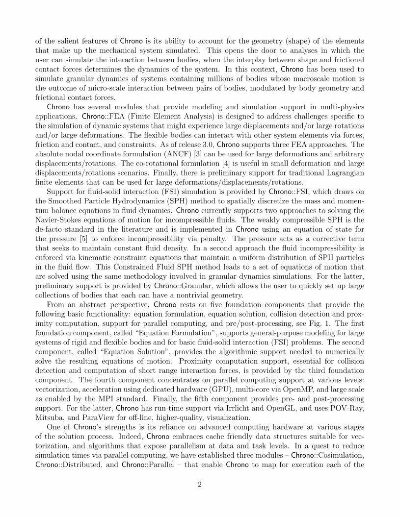
From an abstract perspective, Chrono rests on five foundation components that provide thefollowing basic functionality: equation formulation, equation solution, collision detection and prox-imity computation, support for parallel computing, and pre/post-processing, see Fig. 1. The firstfoundation component, called “Equation Formulation”, supports general-purpose modeling for largesystems of rigid and flexible bodies and for basic fluid-solid interaction (FSI) problems. The secondcomponent, called “Equation Solution”, provides the algorithmic support needed to numericallysolve the resulting equations of motion. Proximity computation support, essential for collisiondetection and computation of short range interaction forces, is provided by the third foundationcomponent. The fourth component concentrates on parallel computing support at various levels:vectorization, acceleration using dedicated hardware (GPU), multi-core via OpenMP, and large scaleas enabled by the MPI standard. Finally, the fifth component provides pre- and post-processingsupport. For the latter, Chrono has run-time support via Irrlicht and OpenGL, and uses POV-Ray,Mitsuba, and ParaView for off-line, higher-quality, visualization.
One of Chrono’s strengths is its reliance on advanced computing hardware at various stagesof the solution process. Indeed, Chrono embraces cache friendly data structures suitable for vec-torization, and algorithms that expose parallelism at data and task levels. In a quest to reducesimulation times via parallel computing, we have established three modules – Chrono::Cosimulation,Chrono::Distributed, and Chrono::Parallel – that enable Chrono to map for execution each of the
2
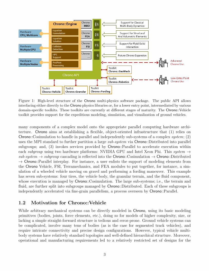
Figure 1: High-level structure of the Chrono multi-physics software package. The public API allowsinterfacing either directly to the Chrono physics libraries or, for a lower entry point, intermediated by variousdomain-specific toolkits. These toolkits are currently at different stages of maturity. The Chrono::Vehicletoolkit provides support for the expeditious modeling, simulation, and visualization of ground vehicles.
many components of a complex model onto the appropriate parallel computing hardware archi-tecture. Chrono aims at establishing a flexible, object-oriented infrastructure that (1) relies onChrono::Cosimulation to handle in parallel and independently sub-systems of a complex system; (2)uses the MPI standard to further partition a large sub-system via Chrono::Distributed into parallelsubgroups; and, (3) invokes services provided by Chrono::Parallel to accelerate execution withineach subgroup using two hardware platforms: NVIDIA GPU and Intel Xeon Phi. This system →sub-system → subgroup cascading is reflected into the Chrono::Cosimulation→ Chrono::Distributed→ Chrono::Parallel interplay. For instance, a user enlists the support of modeling elements fromthe Chrono Vehicle, FSI, Terramechanics, and FEA modules to put together, for instance, a sim-ulation of a wheeled vehicle moving on gravel and performing a fording maneuver. This examplehas seven sub-systems: four tires, the vehicle body, the granular terrain, and the fluid component,whose execution is managed by Chrono::Cosimulation. The large sub-systems; i.e., the terrain andfluid, are further split into subgroups managed by Chrono::Distributed. Each of these subgroups isindependently accelerated via fine-grain parallelism, a process overseen by Chrono::Parallel.
1.2 Motivation for Chrono::Vehicle
While arbitrary mechanical systems can be directly modeled in Chrono, using its basic modelingprimitives (bodies, joints, force elements, etc.), doing so for models of higher complexity, size, orlacking a simple straight-forward structure is tedious and error-prone. Ground vehicle systems canbe complicated, involve many tens of bodies (as is the case for segmented track vehicles), andrequire intricate connectivity and precise design configurations. However, typical vehicle multi-body systems have relatively standard topologies and well-defined hierarchical structure. Moreover,operational and manufacturing requirements led to a relatively restricted set of designs for the
3
main vehicle sub-assemblies, such as suspensions, steering mechanism, track assemblies, etc. Asrecognized by most commercial multi-body dynamics software vendors [6, 7, 8] and by some open-source multi-body simulation software developers, this suggests the design of modeling tools basedon predefined parameterized templates for the major ground vehicle subsystems. A template-basedmodeling capability thus enables the expeditious creation of new vehicles, allows rapid prototyping,and facilitates model re-use.
Chrono::Vehicle is the embodiment of this approach in the Chrono software suite. Its modulardesign, consistent API, rich set of templates, and organization of the simulation time integrationloop additionally enable easy replacement of various systems (”plug-and-play” philosophy) andseamless interfacing to third-party libraries. The architecture of the Chrono::Vehicle module allowsboth fully coupled and co-simulation approaches for vehicle-terrain simulations. In the latter case,the vehicle, terrain, engine, and driver systems evolve in parallel with periodic data communication,for example in an explicit force–displacement co-simulation framework [9, 10].
In addition to providing Chrono users with the expected benefits of template-based ground ve-hicle modeling, Chrono::Vehicle was also architected and designed to leverage existing and futureextensions modeling capabilities in Chrono and capitalize on its underlying high-performance andparallel computing facilities. Chrono::Vehicle models can be easily incorporated in complex, multi-physics simulations, such as flexible tires on granular terrain [9], fluid-solid interaction (FSI) fordingscenarios [11], and autonomous and connected vehicle tests [12].
2 Template-based modeling
Chrono::Vehicle provides a collection of templates for various topologies of both wheeled and trackedvehicle subsystems, support for modeling rigid, flexible, and granular terrain, support for closed-loopand interactive driver models, and run-time and off-line visualization of simulation results.
Modeling of vehicle systems is done in a modular fashion, with a vehicle defined as an assemblyof instances of various subsystems (suspension, steering, driveline, etc.). Flexibility in modelingis provided by adopting a template-based design. In Chrono::Vehicle, templates are parameterizedmodels that define a particular implementation of a vehicle subsystem. As such, a template de-fines the basic modeling elements (bodies, joints, force elements), imposes the subsystem topology,prescribes the design parameters, and implements the common functionality for a given type ofsubsystem (e.g., suspension) particularized to a specific template (e.g., double wishbone). Finally,an instantiation of such a template is obtained by specifying the template parameters (hardpoints,joint directions, inertial properties, contact material properties, etc.) for a concrete vehicle (e.g.,the HMMWV front suspension).
The core templates in Chrono::Vehicle are parameterized models of vehicle subcomponents. How-ever, a complete vehicle mobility simulation also requires auxiliary systems, external to the vehicleitself, such as a driver system to provide input controls (e.g., steering, throttle, braking), a pow-ertrain system which encapsulates the engine and transmission and connects to the the vehicledriveline, and a terrain system.
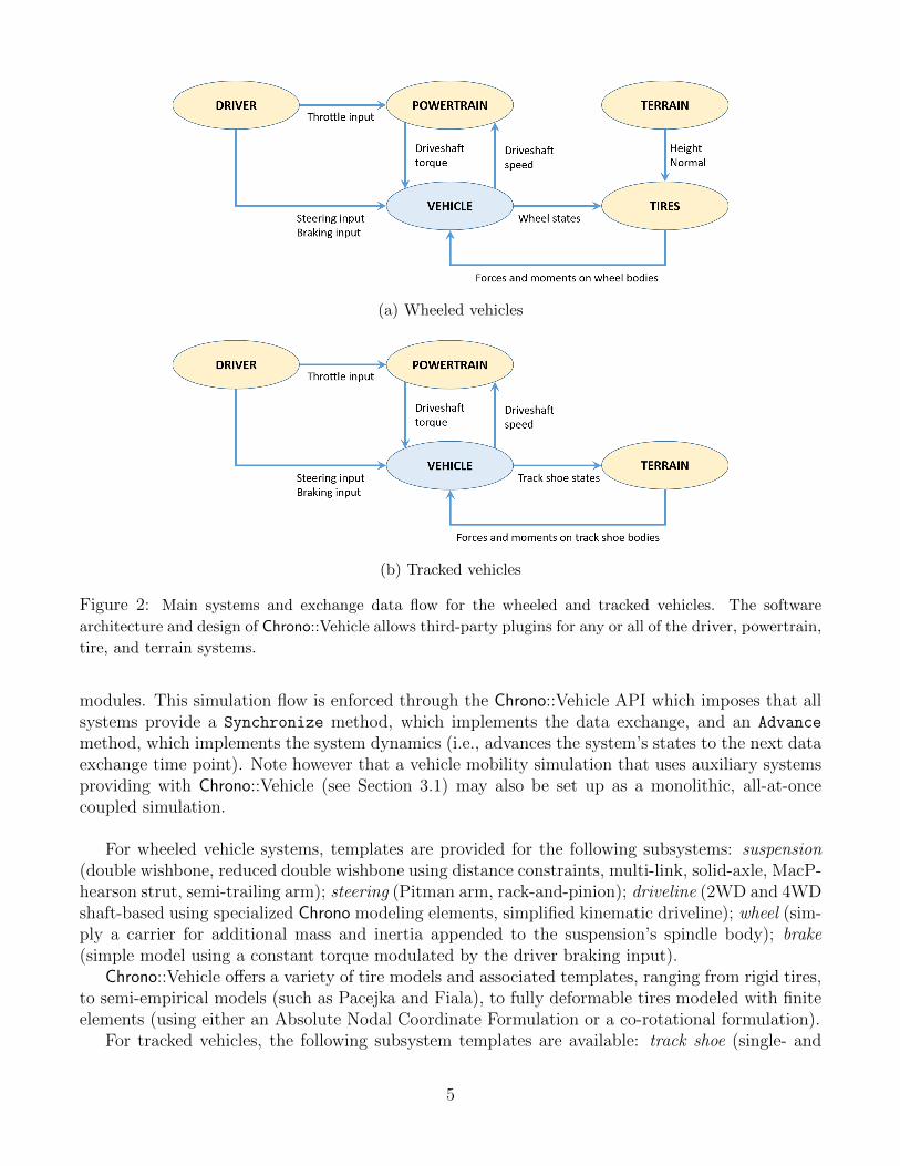
A Chrono::Vehicle simulation loop takes the form of a force-displacement co-simulation scheme,with the exchange data illustrated in Fig. 2a for wheeled vehicles and Fig. 2b for tracked vehicles.This software architecture was adopted in order to (i) provide modularity and flexibility; (ii) permituse of third-party auxiliary system models and integration of Chrono::Vehicle models in largersimulation frameworks; and (iii) enable co-simulation with external tools or with other Chrono
4
(a) Wheeled vehicles
(b) Tracked vehicles
Figure 2: Main systems and exchange data flow for the wheeled and tracked vehicles. The software
architecture and design of Chrono::Vehicle allows third-party plugins for any or all of the driver, powertrain,
tire, and terrain systems.
modules. This simulation flow is enforced through the Chrono::Vehicle API which imposes that allsystems provide a Synchronize method, which implements the data exchange, and an Advance
method, which implements the system dynamics (i.e., advances the system’s states to the next dataexchange time point). Note however that a vehicle mobility simulation that uses auxiliary systemsproviding with Chrono::Vehicle (see Section 3.1) may also be set up as a monolithic, all-at-oncecoupled simulation.
For wheeled vehicle systems, templates are provided for the following subsystems: suspension(double wishbone, reduced double wishbone using distance constraints, multi-link, solid-axle, MacP-hearson strut, semi-trailing arm); steering (Pitman arm, rack-and-pinion); driveline (2WD and 4WDshaft-based using specialized Chrono modeling elements, simplified kinematic driveline); wheel (sim-ply a carrier for additional mass and inertia appended to the suspension’s spindle body); brake(simple model using a constant torque modulated by the driver braking input).
Chrono::Vehicle offers a variety of tire models and associated templates, ranging from rigid tires,to semi-empirical models (such as Pacejka and Fiala), to fully deformable tires modeled with finiteelements (using either an Absolute Nodal Coordinate Formulation or a co-rotational formulation).
For tracked vehicles, the following subsystem templates are available: track shoe (single- and
5
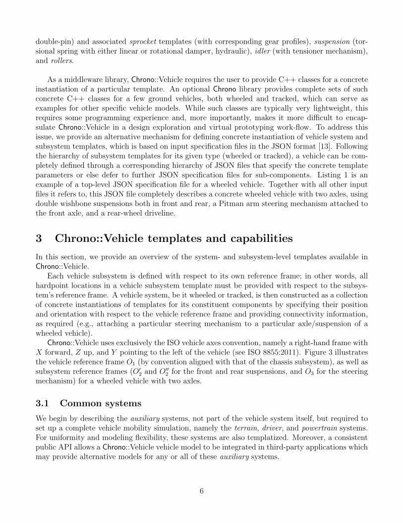
double-pin) and associated sprocket templates (with corresponding gear profiles), suspension (tor-sional spring with either linear or rotational damper, hydraulic), idler (with tensioner mechanism),and rollers.
As a middleware library, Chrono::Vehicle requires the user to provide C++ classes for a concreteinstantiation of a particular template. An optional Chrono library provides complete sets of suchconcrete C++ classes for a few ground vehicles, both wheeled and tracked, which can serve asexamples for other specific vehicle models. While such classes are typically very lightweight, thisrequires some programming experience and, more importantly, makes it more difficult to encap-sulate Chrono::Vehicle in a design exploration and virtual prototyping work-flow. To address thisissue, we provide an alternative mechanism for defining concrete instantiation of vehicle system andsubsystem templates, which is based on input specification files in the JSON format [13]. Followingthe hierarchy of subsystem templates for its given type (wheeled or tracked), a vehicle can be com-pletely defined through a corresponding hierarchy of JSON files that specify the concrete templateparameters or else defer to further JSON specification files for sub-components. Listing 1 is anexample of a top-level JSON specification file for a wheeled vehicle. Together with all other inputfiles it refers to, this JSON file completely describes a concrete wheeled vehicle with two axles, usingdouble wishbone suspensions both in front and rear, a Pitman arm steering mechanism attached tothe front axle, and a rear-wheel driveline.
3 Chrono::Vehicle templates and capabilities
In this section, we provide an overview of the system- and subsystem-level templates available inChrono::Vehicle.
Each vehicle subsystem is defined with respect to its own reference frame; in other words, allhardpoint locations in a vehicle subsystem template must be provided with respect to the subsys-tem’s reference frame. A vehicle system, be it wheeled or tracked, is then constructed as a collectionof concrete instantiations of templates for its constituent components by specifying their positionand orientation with respect to the vehicle reference frame and providing connectivity information,as required (e.g., attaching a particular steering mechanism to a particular axle/suspension of awheeled vehicle).
Chrono::Vehicle uses exclusively the ISO vehicle axes convention, namely a right-hand frame withX forward, Z up, and Y pointing to the left of the vehicle (see ISO 8855:2011). Figure 3 illustratesthe vehicle reference frame O1 (by convention aligned with that of the chassis subsystem), as well assubsystem reference frames (O′
2 and O′′2 for the front and rear suspensions, and O3 for the steering
mechanism) for a wheeled vehicle with two axles.
3.1 Common systems
We begin by describing the auxiliary systems, not part of the vehicle system itself, but required toset up a complete vehicle mobility simulation, namely the terrain, driver, and powertrain systems.For uniformity and modeling flexibility, these systems are also templatized. Moreover, a consistentpublic API allows a Chrono::Vehicle vehicle model to be integrated in third-party applications whichmay provide alternative models for any or all of these auxiliary systems.
6
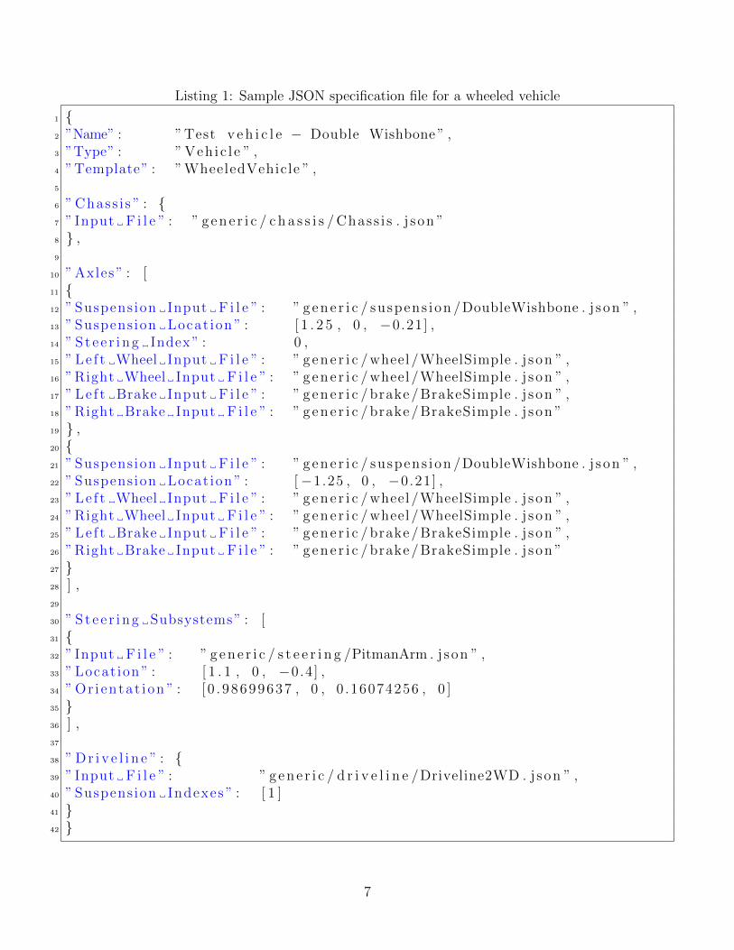
Listing 1: Sample JSON specification file for a wheeled vehicle
1 {2 ”Name” : ” Test v e h i c l e − Double Wishbone ” ,3 ”Type” : ” Veh ic l e ” ,4 ”Template” : ” WheeledVehicle ” ,5
6 ” Chass i s ” : {7 ” Input F i l e ” : ” g e n e r i c / c h a s s i s / Chass i s . j s on ”8 } ,9
10 ” Axles ” : [11 {12 ” Suspension Input F i l e ” : ” g e n e r i c / suspens ion /DoubleWishbone . j son ” ,13 ” Suspension Locat ion ” : [ 1 . 2 5 , 0 , −0.21] ,14 ” S t e e r i ng Index ” : 0 ,15 ” Le f t Wheel Input F i l e ” : ” g e n e r i c / wheel /WheelSimple . j son ” ,16 ” Right Wheel Input F i l e ” : ” g e n e r i c / wheel /WheelSimple . j son ” ,17 ” Le f t Brake Input F i l e ” : ” g e n e r i c / brake / BrakeSimple . j son ” ,18 ” Right Brake Input F i l e ” : ” g e n e r i c / brake / BrakeSimple . j s on ”19 } ,20 {21 ” Suspension Input F i l e ” : ” g e n e r i c / suspens ion /DoubleWishbone . j son ” ,22 ” Suspension Locat ion ” : [−1.25 , 0 , −0.21] ,23 ” Le f t Wheel Input F i l e ” : ” g e n e r i c / wheel /WheelSimple . j son ” ,24 ” Right Wheel Input F i l e ” : ” g e n e r i c / wheel /WheelSimple . j son ” ,25 ” Le f t Brake Input F i l e ” : ” g e n e r i c / brake / BrakeSimple . j son ” ,26 ” Right Brake Input F i l e ” : ” g e n e r i c / brake / BrakeSimple . j s on ”27 }28 ] ,29
30 ” S t e e r i ng Subsystems” : [31 {32 ” Input F i l e ” : ” g e n e r i c / s t e e r i n g /PitmanArm . j son ” ,33 ” Locat ion ” : [ 1 . 1 , 0 , −0.4] ,34 ” Or i entat i on ” : [ 0 . 98699637 , 0 , 0 .16074256 , 0 ]35 }36 ] ,37
38 ” D r i v e l i n e ” : {39 ” Input F i l e ” : ” g e n e r i c / d r i v e l i n e /Driveline2WD . j son ” ,40 ” Suspension Indexes ” : [ 1 ]41 }42 }
7
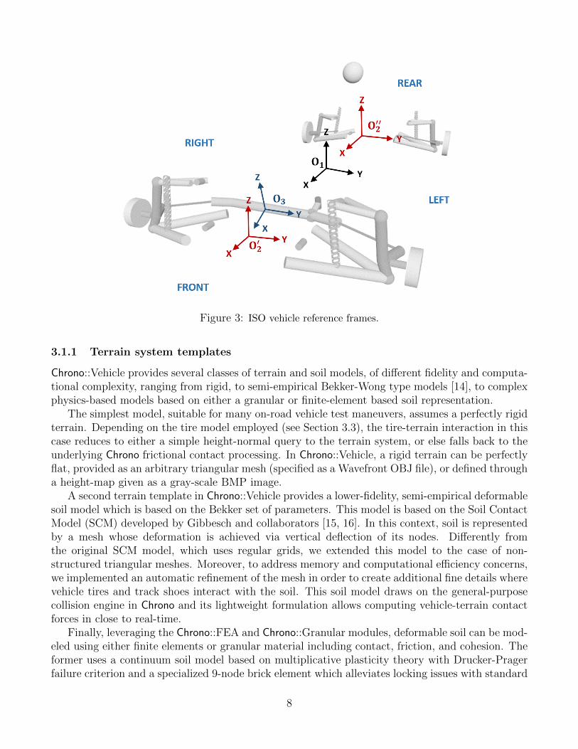
Figure 3: ISO vehicle reference frames.
3.1.1 Terrain system templates
Chrono::Vehicle provides several classes of terrain and soil models, of different fidelity and computa-tional complexity, ranging from rigid, to semi-empirical Bekker-Wong type models [14], to complexphysics-based models based on either a granular or finite-element based soil representation.
The simplest model, suitable for many on-road vehicle test maneuvers, assumes a perfectly rigidterrain. Depending on the tire model employed (see Section 3.3), the tire-terrain interaction in thiscase reduces to either a simple height-normal query to the terrain system, or else falls back to theunderlying Chrono frictional contact processing. In Chrono::Vehicle, a rigid terrain can be perfectlyflat, provided as an arbitrary triangular mesh (specified as a Wavefront OBJ file), or defined througha height-map given as a gray-scale BMP image.
A second terrain template in Chrono::Vehicle provides a lower-fidelity, semi-empirical deformablesoil model which is based on the Bekker set of parameters. This model is based on the Soil ContactModel (SCM) developed by Gibbesch and collaborators [15, 16]. In this context, soil is representedby a mesh whose deformation is achieved via vertical deflection of its nodes. Differently fromthe original SCM model, which uses regular grids, we extended this model to the case of non-structured triangular meshes. Moreover, to address memory and computational efficiency concerns,we implemented an automatic refinement of the mesh in order to create additional fine details wherevehicle tires and track shoes interact with the soil. This soil model draws on the general-purposecollision engine in Chrono and its lightweight formulation allows computing vehicle-terrain contactforces in close to real-time.
Finally, leveraging the Chrono::FEA and Chrono::Granular modules, deformable soil can be mod-eled using either finite elements or granular material including contact, friction, and cohesion. Theformer uses a continuum soil model based on multiplicative plasticity theory with Drucker-Pragerfailure criterion and a specialized 9-node brick element which alleviates locking issues with standard
8
8-node FEA brick elements without the need for numerical techniques such as enhanced assumedstrain [17]. Physics-based deformable soil models based on granular dynamics simulations can beperformed using the underlying Chrono support for the Discrete Element Method (DEM). Un-like continuum-based deformable terrain modeling approaches, DEM treats all component particlesseparately, as distinct entities, by maintaining and advancing in time their states while takinginto account pair-wise interaction forces due to frictional contact. Chrono::Vehicle simulations ongranular terrain can use either of the two methods supported in Chrono, namely a penalty-based,compliant-body approach, or a complementarity-based, rigid-body approach [1]. Since meaningfulmobility simulations of vehicles on granular terrain typically result in DEM problems with millionsof degrees of freedom, these are typically run on parallel hardware, using either the Chrono::Parallelmodule for a coupled vehicle-terrain simulation [18], or else Chrono::Distributed in a co-simulationframework [9, 10].
3.1.2 Driver system templates
Driver inputs (steering, throttle, and braking) are provided from a driver subsystem with availableoptions in ChronoVehicle including interactive, data-driven, and closed-loop (e.g., path-followingbased on PID controllers).
The base C++ class for a driver system in Chrono::Vehicle imposes minimal requirements froma driver system template, in particular the ability to return throttle input (normalized in the [0, 1]range), steering input (normalized in the [−1,+1] range, with a negative value indicating steeringto the left), and braking input (normalized in the [0, 1] range). In addition, a driver system canreceive information from any other system (e.g., the vehicle state) through its Synchronize methodand may have internal dynamics (implemented in its Advance method). Specific templates for adriver system may extend the set of vehicle inputs generated, for example including the currentselected gear for a manual transmission, enabling/disabling the cross-drive capability on a trackedvehicle, etc.
The Chrono::Vehicle library includes several templates for driver systems. For interactive simu-lations, run in soft real-time, we provide a template for a driver system which produces the vehicleinputs based on user controls, either keyboard and mouse, or a game controller. For design of ex-periment simulations, we provide a driver system template that is based on inputs provided througha text data file, with the vehicle inputs obtained through linear interpolation. Such data files canalso be automatically generated by data collected during interactive runs.
Finally, Chrono::Vehicle includes several closed-looped driver system models, based on underlyingsupport for PID controllers. These include speed controllers (which adjust the throttle and brakinginput simultaneously to maintain a constant vehicle speed) and path-follower controllers. The latteradjust the steering input so that the vehicle follows a user-defined path specified as a Bezier curve.A second type of closed-loop driver controllers, developed under the Chrono::CAVE module, providevehicle inputs based on sensor data (LiDAR, GPS, IMU) for simulations involving connected andautonomous vehicles [12] and model-predictive controllers for obstacle-avoidance [19].
3.1.3 Powertrain system templates
Although technically part of the vehicle itself, for additional modeling flexibility and to allow use ofmore sophisticated third-party engine models, Chrono::Vehicle collects the engine, torque converter,and transmission box into a distinct system, separate from the vehicle driveline, as shown in Fig. 4.
9
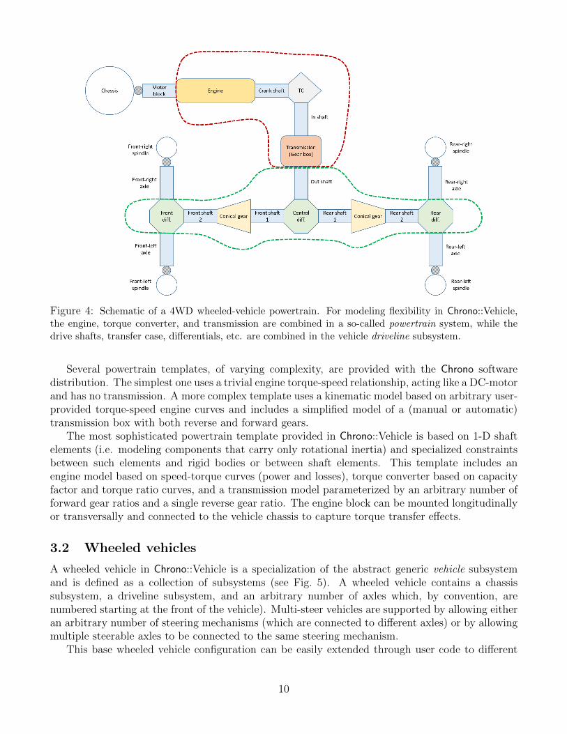
Figure 4: Schematic of a 4WD wheeled-vehicle powertrain. For modeling flexibility in Chrono::Vehicle,the engine, torque converter, and transmission are combined in a so-called powertrain system, while thedrive shafts, transfer case, differentials, etc. are combined in the vehicle driveline subsystem.
Several powertrain templates, of varying complexity, are provided with the Chrono softwaredistribution. The simplest one uses a trivial engine torque-speed relationship, acting like a DC-motorand has no transmission. A more complex template uses a kinematic model based on arbitrary user-provided torque-speed engine curves and includes a simplified model of a (manual or automatic)transmission box with both reverse and forward gears.
The most sophisticated powertrain template provided in Chrono::Vehicle is based on 1-D shaftelements (i.e. modeling components that carry only rotational inertia) and specialized constraintsbetween such elements and rigid bodies or between shaft elements. This template includes anengine model based on speed-torque curves (power and losses), torque converter based on capacityfactor and torque ratio curves, and a transmission model parameterized by an arbitrary number offorward gear ratios and a single reverse gear ratio. The engine block can be mounted longitudinallyor transversally and connected to the vehicle chassis to capture torque transfer effects.
3.2 Wheeled vehicles
A wheeled vehicle in Chrono::Vehicle is a specialization of the abstract generic vehicle subsystemand is defined as a collection of subsystems (see Fig. 5). A wheeled vehicle contains a chassissubsystem, a driveline subsystem, and an arbitrary number of axles which, by convention, arenumbered starting at the front of the vehicle). Multi-steer vehicles are supported by allowing eitheran arbitrary number of steering mechanisms (which are connected to different axles) or by allowingmultiple steerable axles to be connected to the same steering mechanism.
This base wheeled vehicle configuration can be easily extended through user code to different
10
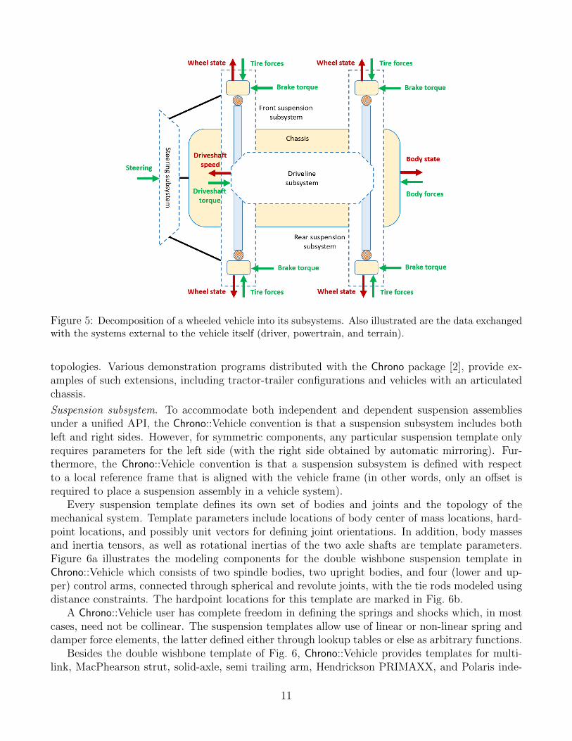
Figure 5: Decomposition of a wheeled vehicle into its subsystems. Also illustrated are the data exchangedwith the systems external to the vehicle itself (driver, powertrain, and terrain).
topologies. Various demonstration programs distributed with the Chrono package [2], provide ex-amples of such extensions, including tractor-trailer configurations and vehicles with an articulatedchassis.
Suspension subsystem. To accommodate both independent and dependent suspension assembliesunder a unified API, the Chrono::Vehicle convention is that a suspension subsystem includes bothleft and right sides. However, for symmetric components, any particular suspension template onlyrequires parameters for the left side (with the right side obtained by automatic mirroring). Fur-thermore, the Chrono::Vehicle convention is that a suspension subsystem is defined with respectto a local reference frame that is aligned with the vehicle frame (in other words, only an offset isrequired to place a suspension assembly in a vehicle system).
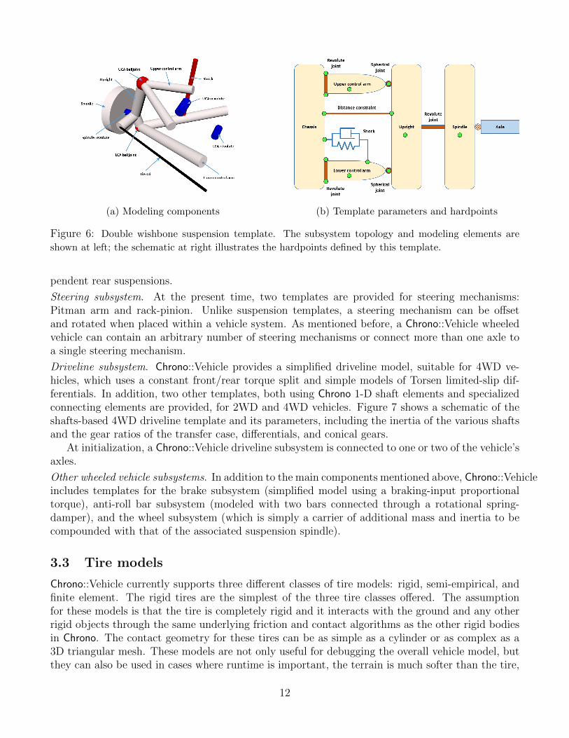
Every suspension template defines its own set of bodies and joints and the topology of themechanical system. Template parameters include locations of body center of mass locations, hard-point locations, and possibly unit vectors for defining joint orientations. In addition, body massesand inertia tensors, as well as rotational inertias of the two axle shafts are template parameters.Figure 6a illustrates the modeling components for the double wishbone suspension template inChrono::Vehicle which consists of two spindle bodies, two upright bodies, and four (lower and up-per) control arms, connected through spherical and revolute joints, with the tie rods modeled usingdistance constraints. The hardpoint locations for this template are marked in Fig. 6b.
A Chrono::Vehicle user has complete freedom in defining the springs and shocks which, in mostcases, need not be collinear. The suspension templates allow use of linear or non-linear spring anddamper force elements, the latter defined either through lookup tables or else as arbitrary functions.
Besides the double wishbone template of Fig. 6, Chrono::Vehicle provides templates for multi-link, MacPhearson strut, solid-axle, semi trailing arm, Hendrickson PRIMAXX, and Polaris inde-
11
(a) Modeling components (b) Template parameters and hardpoints
Figure 6: Double wishbone suspension template. The subsystem topology and modeling elements are
shown at left; the schematic at right illustrates the hardpoints defined by this template.
pendent rear suspensions.
Steering subsystem. At the present time, two templates are provided for steering mechanisms:Pitman arm and rack-pinion. Unlike suspension templates, a steering mechanism can be offsetand rotated when placed within a vehicle system. As mentioned before, a Chrono::Vehicle wheeledvehicle can contain an arbitrary number of steering mechanisms or connect more than one axle toa single steering mechanism.
Driveline subsystem. Chrono::Vehicle provides a simplified driveline model, suitable for 4WD ve-hicles, which uses a constant front/rear torque split and simple models of Torsen limited-slip dif-ferentials. In addition, two other templates, both using Chrono 1-D shaft elements and specializedconnecting elements are provided, for 2WD and 4WD vehicles. Figure 7 shows a schematic of theshafts-based 4WD driveline template and its parameters, including the inertia of the various shaftsand the gear ratios of the transfer case, differentials, and conical gears.
At initialization, a Chrono::Vehicle driveline subsystem is connected to one or two of the vehicle’saxles.
Other wheeled vehicle subsystems. In addition to the main components mentioned above, Chrono::Vehicleincludes templates for the brake subsystem (simplified model using a braking-input proportionaltorque), anti-roll bar subsystem (modeled with two bars connected through a rotational spring-damper), and the wheel subsystem (which is simply a carrier of additional mass and inertia to becompounded with that of the associated suspension spindle).
3.3 Tire models
Chrono::Vehicle currently supports three different classes of tire models: rigid, semi-empirical, andfinite element. The rigid tires are the simplest of the three tire classes offered. The assumptionfor these models is that the tire is completely rigid and it interacts with the ground and any otherrigid objects through the same underlying friction and contact algorithms as the other rigid bodiesin Chrono. The contact geometry for these tires can be as simple as a cylinder or as complex as a3D triangular mesh. These models are not only useful for debugging the overall vehicle model, butthey can also be used in cases where runtime is important, the terrain is much softer than the tire,
12
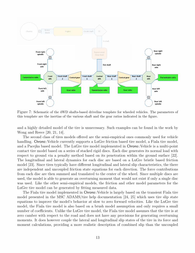
Figure 7: Schematic of the 4WD shafts-based driveline template for wheeled vehicles. The parameters ofthis template are the inertias of the various shaft and the gear ratios indicated in the figure.
and a highly detailed model of the tire is unnecessary. Such examples can be found in the work byWong and Reece [20, 21, 14].
The second class of tires models offered are the semi-empirical ones commonly used for vehiclehandling. Chrono::Vehicle currently supports a LuGre friction based tire model, a Fiala tire model,and a Pacejka based model. The LuGre tire model implemented in Chrono::Vehicle is a multi-pointcontact tire model based on a series of stacked rigid discs. Each disc generates its normal load withrespect to ground via a penalty method based on its penetration within the ground surface [22].The longitudinal and lateral dynamics for each disc are based on a LuGre bristle based frictionmodel [23]. Since tires typically have different longitudinal and lateral slip characteristics, the thereare independent and uncoupled friction state equations for each direction. The force contributionsfrom each disc are then summed and translated to the center of the wheel. Since multiple discs areused, the model is able to generate an overturning moment that would not exist if only a single discwas used. Like the other semi-empirical models, the friction and other model parameters for theLuGre tire model can be generated by fitting measured data.
The Fiala tire model implemented in Chrono::Vehicle is largely based on the transient Fiala tiremodel presented in the MSC ADAMS/tire help documentation [24, 25] which uses tire slip stateequations to improve the model’s behavior at slow to zero forward velocities. Like the LuGre tiremodel, the Fiala tire model is also based on a brush model assumption and only requires a smallnumber of coefficients. Unlike the LuGre tire model, the Fiala tire model assumes that the tire is atzero camber with respect to the road and does not have any provisions for generating overturningmoments. It does however couple the lateral and longitudinal slip states of the tire in its force andmoment calculations, providing a more realistic description of combined slip than the uncoupled
13
approach in the LuGre model.The third and most complex semi-empirical tire model offered is based off of the equations in
Pacejka’s ”Tire and Vehicle Dynamics” book as well as the equations in the MSC ADAMS/tire helpfor the PAC2002 tire model [26, 25]. This model is an extension of Pacejka’s earlier Magic Formulatire model with additional equations and coefficients. Since a large number of vehicle dynamicsmaneuvers do not occur under steady-state slip conditions, the contact patch slip state equationswere included to provide more accurate results under transient conditions. The Chrono::Vehicle im-plementation of Pacejka’s tire model has been validated against the tire test rig in MSC ADAMS/-car [27].
Finally, the third class of tire models offered are full finite element representations of the tire.While these models have the potential to be the most accurate due to their detailed physical modelof the tire, they are also the most computationally expensive of the tire model currently availablein Chrono::Vehicle [9]. Unlike the rigid or semi-empirical tire models, the finite element basedtire models are able to account for the flexibility in both the tire and in the ground at the sametime, which is an important characteristic for many types of off-road mobility and vehicle dynamicsstudies. Since these finite element tire models leverage the nonlinear finite element capabilitiesin Chrono, tires have been modeled using co-rotational continuum elements, co-rotational shellelements, and ANCF shell elements.
3.4 Tracked vehicles
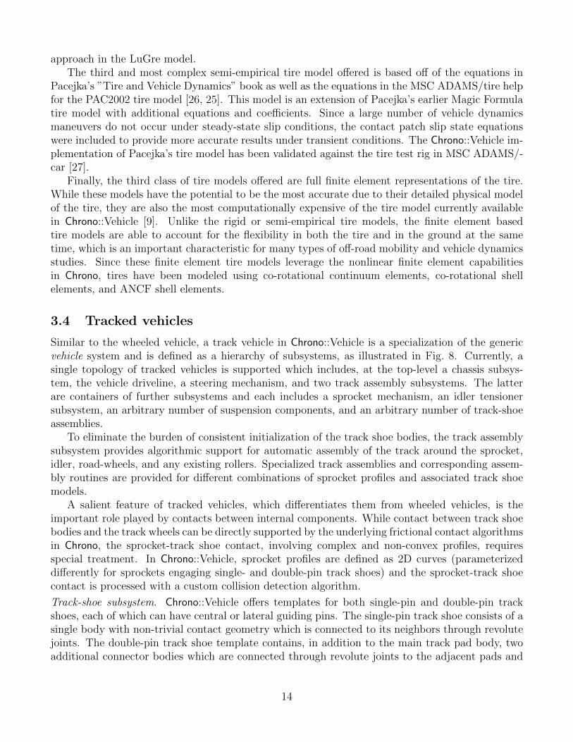
Similar to the wheeled vehicle, a track vehicle in Chrono::Vehicle is a specialization of the genericvehicle system and is defined as a hierarchy of subsystems, as illustrated in Fig. 8. Currently, asingle topology of tracked vehicles is supported which includes, at the top-level a chassis subsys-tem, the vehicle driveline, a steering mechanism, and two track assembly subsystems. The latterare containers of further subsystems and each includes a sprocket mechanism, an idler tensionersubsystem, an arbitrary number of suspension components, and an arbitrary number of track-shoeassemblies.
To eliminate the burden of consistent initialization of the track shoe bodies, the track assemblysubsystem provides algorithmic support for automatic assembly of the track around the sprocket,idler, road-wheels, and any existing rollers. Specialized track assemblies and corresponding assem-bly routines are provided for different combinations of sprocket profiles and associated track shoemodels.
A salient feature of tracked vehicles, which differentiates them from wheeled vehicles, is theimportant role played by contacts between internal components. While contact between track shoebodies and the track wheels can be directly supported by the underlying frictional contact algorithmsin Chrono, the sprocket-track shoe contact, involving complex and non-convex profiles, requiresspecial treatment. In Chrono::Vehicle, sprocket profiles are defined as 2D curves (parameterizeddifferently for sprockets engaging single- and double-pin track shoes) and the sprocket-track shoecontact is processed with a custom collision detection algorithm.
Track-shoe subsystem. Chrono::Vehicle offers templates for both single-pin and double-pin trackshoes, each of which can have central or lateral guiding pins. The single-pin track shoe consists of asingle body with non-trivial contact geometry which is connected to its neighbors through revolutejoints. The double-pin track shoe template contains, in addition to the main track pad body, twoadditional connector bodies which are connected through revolute joints to the adjacent pads and
14
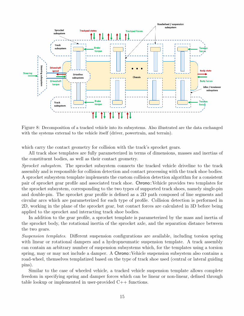
Figure 8: Decomposition of a tracked vehicle into its subsystems. Also illustrated are the data exchangedwith the systems external to the vehicle itself (driver, powertrain, and terrain).
which carry the contact geometry for collision with the track’s sprocket gears.All track shoe templates are fully parameterized in terms of dimensions, masses and inertias of
the constituent bodies, as well as their contact geometry.
Sprocket subsystem. The sprocket subsystem connects the tracked vehicle driveline to the trackassembly and is responsible for collision detection and contact processing with the track shoe bodies.A sprocket subsystem template implements the custom collision detection algorithm for a consistentpair of sprocket gear profile and associated track shoe. Chrono::Vehicle provides two templates forthe sprocket subsystem, corresponding to the two types of supported track shoes, namely single-pinand double-pin. The sprocket gear profile is defined as a 2D path composed of line segments andcircular arcs which are parameterized for each type of profile. Collision detection is performed in2D, working in the plane of the sprocket gear, but contact forces are calculated in 3D before beingapplied to the sprocket and interacting track shoe bodies.
In addition to the gear profile, a sprocket template is parameterized by the mass and inertia ofthe sprocket body, the rotational inertia of the sprocket axle, and the separation distance betweenthe two gears.
Suspension templates. Different suspension configurations are available, including torsion springwith linear or rotational dampers and a hydropneumatic suspension template. A track assemblycan contain an arbitrary number of suspension subsystems which, for the templates using a torsionspring, may or may not include a damper. A Chrono::Vehicle suspension subsystem also contains aroad-wheel, themselves templatized based on the type of track shoe used (central or lateral guidingpins).
Similar to the case of wheeled vehicle, a tracked vehicle suspension template allows completefreedom in specifying spring and damper forces which can be linear or non-linear, defined throughtable lookup or implemented in user-provided C++ functions.
15
Idler subsystem. A Chrono::Vehicle idler mechanism consists of the idler wheel and a connectingbody. The idler wheel is connected through a revolute joint to the connecting body which in turn isconnected to the chassis through a translational joint. A linear actuator acts as a tensioner whichis modeled as a general spring-damper with optional preload. An idler subsystem is defined withrespect to a frame centered at the origin of the idler wheel, optionally pitched relative to the chassisreference frame. The translational joint is aligned with the X axis of this reference frame, whilethe axis of rotation of the revolute joint is aligned with its Y axis.
Like the road-wheels, different templates are provided for the case of tracks with central orlateral guiding pins.
3.5 Visualization and post-processing
Chrono::Vehicle provides visualization support both for run-time interactive simulations, as well asfor high-quality post-processing rendering for generating animations. Currently, run-time simulationsupport expands on the underlying Chrono::Irrlicht module for sequential simulations [28] or themore computationally efficient but more limited Chrono::OpenGL module for parallel simulationsinvolving large-scale granular terrain representations [29]. Ongoing development effort involves atransition to an Ogre-based run-time visualization system [30], as a replacement for Chrono::Irrlicht.Support for ray-traced renderings of individual simulation frames is offered through utility functionsthat can be called from within the simulation loop to export data files with current visualizationassets information and a POV-Ray script [31] that can batch-process these files to generate frameimages.
Extraction of simulation results at vehicle-, subsystem-, or model component-level is currentlylimited to using the Chrono::Vehicle C++ API which provides an exhaustive set of methods forthis purpose, as well as utility for data filtering, I/O, etc. A specialized module is currently underdevelopment to provide a formal mechanism for extracting a list of all available output channelsand metrics of interest from a vehicle simulation, automatic data collection during the simulation,and final reporting and plotting of user-specified quantities of interest.
4 Ground vehicle mobility simulations with Chrono::Vehicle
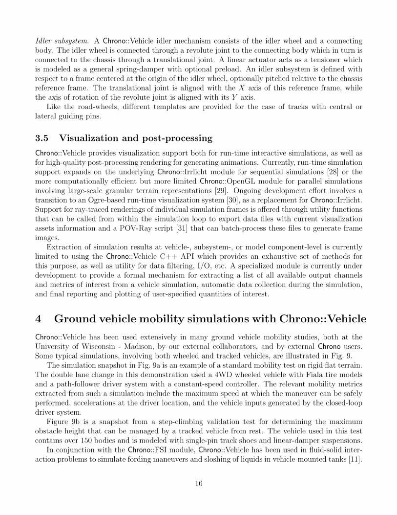
Chrono::Vehicle has been used extensively in many ground vehicle mobility studies, both at theUniversity of Wisconsin - Madison, by our external collaborators, and by external Chrono users.Some typical simulations, involving both wheeled and tracked vehicles, are illustrated in Fig. 9.
The simulation snapshot in Fig. 9a is an example of a standard mobility test on rigid flat terrain.The double lane change in this demonstration used a 4WD wheeled vehicle with Fiala tire modelsand a path-follower driver system with a constant-speed controller. The relevant mobility metricsextracted from such a simulation include the maximum speed at which the maneuver can be safelyperformed, accelerations at the driver location, and the vehicle inputs generated by the closed-loopdriver system.
Figure 9b is a snapshot from a step-climbing validation test for determining the maximumobstacle height that can be managed by a tracked vehicle from rest. The vehicle used in this testcontains over 150 bodies and is modeled with single-pin track shoes and linear-damper suspensions.
In conjunction with the Chrono::FSI module, Chrono::Vehicle has been used in fluid-solid inter-action problems to simulate fording maneuvers and sloshing of liquids in vehicle-mounted tanks [11].
16
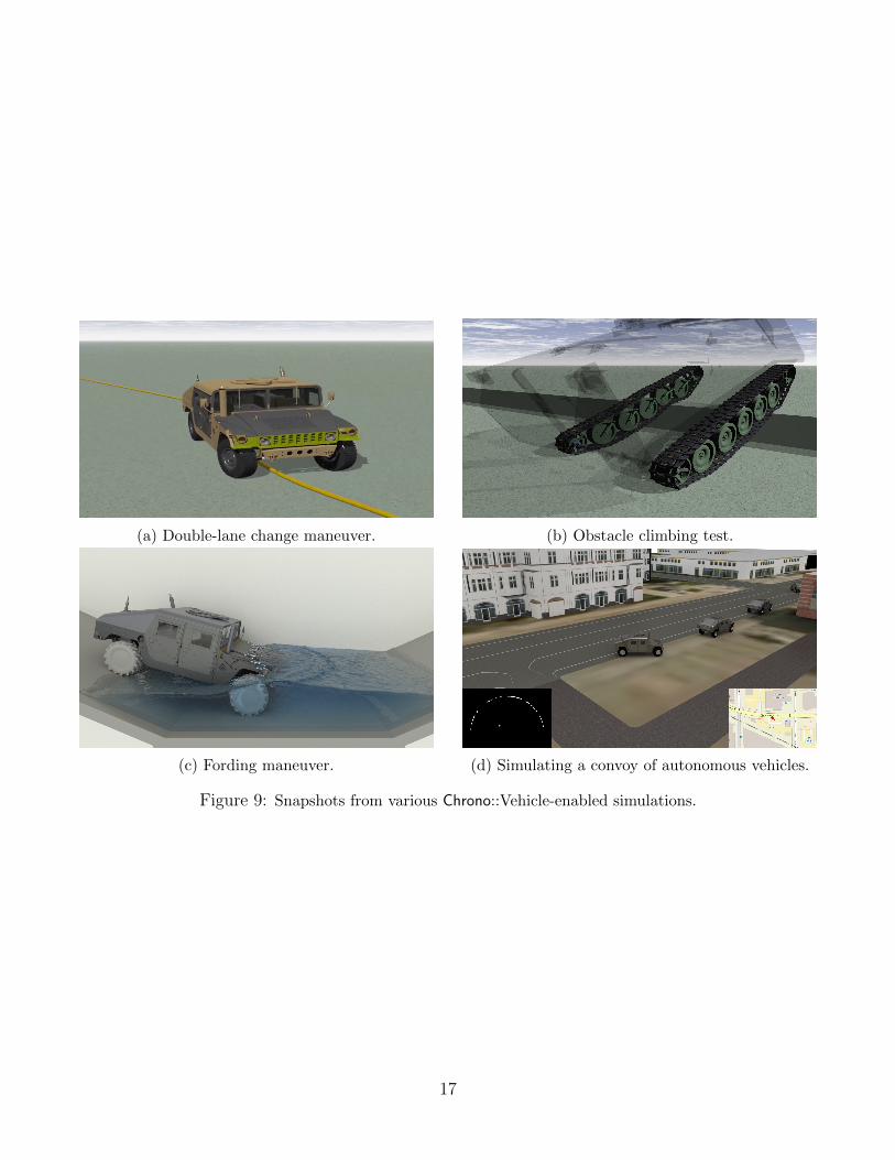
(a) Double-lane change maneuver. (b) Obstacle climbing test.
(c) Fording maneuver. (d) Simulating a convoy of autonomous vehicles.
Figure 9: Snapshots from various Chrono::Vehicle-enabled simulations.
17
These simulations capture the two-way coupling between the vehicle dynamics and the fluid phase,the latter being governed by the mass and momentum (Navier-Stokes) equations discretized in spacevia SPH. The simulation illustrated in Fig. 9c involved a 4WD wheeled vehicle with a constant-speed controller negotiating a body of water and fully accounts for the interaction between the fluidphase and the vehicle chassis and tires (for collision detection purposes, the chassis and tire mesheswere decomposed in sets of convex hulls). This simulation used approximately 1.5 million SPHparticles for the fluid phase and was carried out with Chrono::Parallel using 40 OpenMP.
Figure 9d is a snapshot from a simulation with Chrono::CAVE implementing functionality fromChrono::Vehicle, multiple agents, sensors, and a virtual world [12]. This setup involves four vehiclessimulated on separate network clients, all connected to a single server. The lead vehicle is interac-tively driven and the three trailing vehicles are autonomous. The latter are equipped with virtualLiDAR, GPS, and IMU sensors which are used in a simple driver controller to follow the vehicleahead. The outputs of these sensors are overlaid (LiDAR on the left and GPS/IMU combined onthe right) for the last vehicle in the convoy.
As examples of other types of simulations enabled by Chrono::Vehicle we mention studies ofwheeled vehicles with flexible tires on granular terrain [9, 10] to investigate the effect of tireand terrain deformation on mobility metrics; and design of model predictive controllers for ob-stacle avoidance on deformable terrain [19] to investigate controller performance and robustness.Chrono::Vehicle is an integral part of the Mercury framework for mobility simulation of wheeledground vehicles [32].
5 Conclusions and future developments
We provided a brief overview of the Chrono::Vehicle library which provides support for ground vehiclemodeling, simulation, and visualization within the multi-physics package Chrono. This module is de-signed in a modular manner, using a template-based approach to allow rapid prototyping of existingand new vehicle configurations and to facilitate its integration in third-party simulation frameworks.The simulation loop in Chrono::Vehicle is structured such that it permits both monolithic coupledvehicle simulations and co-simulation for large-scale vehicle–terrain–environment multi-physics andmulti-scale simulation.
Current and planned development involves inclusion of additional subsystem templates, such assupport for continuous rubber band tracked vehicles, as well as new capabilities, primarily relatedto formalization of data collection, output of mobility metrics, and post-processing.
Complex vehicle–terrain simulations, particularly those involving high-fidelity FEA-based flex-ible tires, granular terrain, and multi-phase FSI problems, continue to pose serious challenges,including the still considerable computational requirements. Plans for future research and devel-opment in this area focus on leveraging hybrid parallel computing as enabled by the interplay ofChrono::Distributed and Chrono::Parallel in a co-simulation framework.
Acknowledgments
Support for this work was provided by U.S. Army grants W56HZV-08-C-0236 and W56HZV-08-C-0236.We acknowledge past and current contributions by Asher Elmquist, Holger Haut, Justin Madsen,Daniel Melanz, and Antonio Recuero.
18
References
[1] A. Tasora, R. Serban, H. Mazhar, A. Pazouki, D. Melanz, J. Fleischmann, M. Taylor,H. Sugiyama, and D. Negrut. Chrono: An open source multi-physics dynamics engine. InT. Kozubek, editor, High Performance Computing in Science and Engineering – Lecture Notesin Computer Science, pages 19–49. Springer, 2016.
[2] Project Chrono Development Team. Chrono: An Open Source Framework for the Physics-BasedSimulation of Dynamic Systems. https://github.com/projectchrono/chrono. Accessed:2017-05-07.
[3] A. A. Shabana and R. Y. Yakoub. Three dimensional absolute nodal coordinate formulationfor beam elements: Theory. ASME Journal of Mechanical Design, 123:606–613, 2001.
[4] J. C. Simo and L. Vu-Quoc. Three-dimensional finite-strain rod model. part ii: Computationalaspects. Computer Methods in Applied Mechanics and Engineering, 58:79–116, 1986.
[5] R. A. Gingold and J. J. Monaghan. Kernel estimates as a basis for general particle methodsin hydrodynamics. Journal of Computational Physics, 46(3):429–453, 1982.
[6] MSC Software. ADAMS. http://www.mscsoftware.com/product/adams. Accessed: 2015-02-07.
[7] Siemens PLM Software. Siemens Virtual.Lab. https://www.plm.automation.siemens.com/en_us/products/lms/virtual-lab/. Accessed: 2016-09-13.
[8] FunctionBay. Recurdyn. http://eng.functionbay.co.kr. Accessed: 2015-02-07.
[9] A. M. Recuero, R. Serban, B. Peterson, H. Sugiyama, P. Jayakumar, and D. Negrut. A high-fidelity approach for vehicle mobility simulation: Nonlinear finite element tires operating ongranular material. Journal of Terramechanics, 72:39 – 54, 2017.
[10] R. Serban, N. Olsen, D. Negrut, A. M. Recuero, and P. Jayakumar. A co-simulation frameworkfor high-performance, high-fidelity simulation of ground vehicle-terrain interaction. In AVT-265: Integrated Virtual NATO Vehicle Development, Vilnius, Lithuania, May 2017.
[11] H. Mazhar, A. Pazouki, M. Rakhsha, P. Jayakumar, and D. Negrut. A differential variationalapproach for handling fluid-solid interaction problems via Smoothed Particle Hydrodynamics.Journal of Computational Physics (under review), 0:0, 2017.
[12] A. Elmquist, D. Hatch, C. Ricchio, R. Serban, and D. Negrut. Virtual autonomous vehicletesting via a Connected Autonomous Vehicle Emulator (CAVE). In J. Michopoulos, D. Rosen,C. Paredis, and J. Vance, editors, Advances in Computers and Information in EngineeringResearch. ASME Press, New York, 2017.
[13] ECMA. The JSON data interchange format. Technical Report ECMA-404, ECMA Interna-tional, 2013.
[14] J. Y. Wong. Theory of Ground Vehicles. John Wiley & Sons, New York, 2001.
19
[15] A. Gibbesch and B. Schafer. Multibody system modelling and simulation of planetary rovermobility on soft terrain. In 8th International Symposium on Artificial Intelligence, Roboticsand Automation in Space (i-SAIRAS 2005), Munich, Germany, September, pages 5–8, 2005.
[16] R. Krenn and A. Gibbesch. Soft soil contact modeling technique for multi-body system simu-lation. In Trends in computational contact mechanics, pages 135–155. Springer, 2011.
[17] H. Yamashita, P. Jayakumar, and H. Sugiyama. Modeling of deformable tire and soil interactionusing multiplicative finite plasticity for multibody off-road mobility simulation. In Proceedingsof the ASME 2016 International Design Engineering Technical Conferences and Computersand Information in Engineering Conference IDETC/CIE 2016, 2016.
[18] A. Pazouki, M. Kwarta, K. Williams, W. Likos, R. Serban, J. Jayakumar, and D. Negrut.Compliant versus rigid contact – a comparison in the context of granular dynamics. Phys. Rev.E (under review), 0:0, 2017.
[19] N. Haraus, R. Serban, and J. Fleischmann. Performance analysis of constant speed localobstacle avoidance controller using an MPC algorithm on granular terrain. In Ground VehicleSystems Engineering and Technology Symposium, 2017.
[20] J. Y. Wong and A. R. Reece. Prediction of rigid wheel performance based on the analysisof soil-wheel stresses part i. performance of driven rigid wheels. Journal of Terramechanics,4(1):81–98, 1967.
[21] J. Y. Wong and A. R. Reece. Prediction of rigid wheel performance based on the analysisof soil-wheel stresses: Part ii. performance of towed rigid wheels. Journal of Terramechanics,4(2):7–25, 1967.
[22] A. Mikkola. Lugre Tire Model for HMMWV. Technical Report TR-2014-15: http://sbel.
wisc.edu/documents/TR-2014-15.pdf, Simulation-Based Engineering Laboratory, Univer-sity of Wisconsin-Madison, 2014.
[23] N. B. Do, A. A. Ferri, and O. A. Bauchau. Efficient simulation of a dynamic system with lugrefriction. Journal of Computational and Nonlinear Dynamics, 2(4):281–289, 2007.
[24] M. Taylor. Implementation and validation of the Fiala tire model in Chrono. Technical ReportTR-2015-13: http://sbel.wisc.edu/documents/TR-2016-06.pdf, University of Wisconsin–Madison, 2015.
[25] MSC Software. ADAMS/Tire help - ADAMS 2015. https://simcompanion.mscsoftware.
com/infocenter/index?page=content&id=DOC10813&cat=2015_ADAMS_DOCS&actp=LIST/,July 2015.
[26] H. B. Pacejka. Tire and vehicle dynamics. Elsevier, 2005.
[27] J. Madsen. Validation of a Single Contact Point Tire Model Based on the Transient Pace-jka Model in the Open-Source Dynamics Software Chrono. Technical Report TR-2014-16:http://sbel.wisc.edu/documents/TR-2014-16.pdf, Simulation-Based Engineering Labora-tory, University of Wisconsin-Madison, 2014.
20
[28] Irrlicht. Open Source 3D Irrlicht Engine. http://irrlicht.sourceforge.net/, 2014.
[29] Khronos Group. Open Graphics Library - OpenGL. http://www.opengl.org/, 2014.
[30] I. Milne and G. Rowe. OGRE-3D program visualization for C++. In Proceedings of the 3rdAnnual LTSN-ICS Conference, 2002.
[31] Persistence of Vision Pty. Ltd. Persistence of Vision (TM) Raytracer. http://www.povray.org,2004.
[32] C. Goodin, J. Mange, S. Pace, T. Skorupa, D. Kedziorek, J. Priddy, and L. Lynch. Simulatingthe mobility of wheeled ground vehicles with mercury. SAE Int. J. Commer. Veh., 10(2), 2017.
21