Embed Size (px)
Citation preview
Int. J. Vehicle Performance, Vol. x, No. x, 1–20 1
Chrono::Vehicle – Template-Based Ground VehicleModeling and Simulation
Abstract: Chrono::Vehicle is a module of the open-source multi-physicssimulation package Chrono, aimed at modeling, simulation, and visualization ofwheeled and tracked ground vehicle multi-body systems. Its software architectureand design was dictated by the desire to provide an expeditious and user-friendly mechanism for assembling complex vehicle models, while leveragingthe underlying Chrono modeling and simulation capabilities, allowing seamlessinterfacing to other optional Chrono modules (e.g., its granular dynamics andfluid-solid interaction capabilities), and providing a modular and expressive APIto facilitate its use in third-party applications. Vehicle models are specified asa hierarchy of subsystems, each of which is an instantiation of a predefinedsubsystem template. Written in C++, Chrono::Vehicle is offered as a middlewarelibrary.
In this paper, we provide an overview of the Chrono::Vehicle software designphilosophy, its main capabilities and features, describe the types of groundvehicle mobility simulations it enables, and outline several directions of futuredevelopment and planned extensions.
Keywords: Chrono; Vehicle modeling; Template-based design; JSON.
1 Introduction
1.1 Brief overview of Chrono
Chrono [27] is an open-source multi-physics software package, which is distributed undera permissive BSD-3 license [22]. The core functionality of Chrono provides support forthe modeling, simulation, and visualization of rigid multibody systems, with additionalcapabilities offered through optional modules. These modules provide support for additionalclasses of problems (e.g., finite element analysis and fluid-solid interaction), for modelingand simulation of specialized systems (such as ground vehicles and granular dynamicsproblems), or for providing specialized parallel computing algorithms (multi-core, GPU,and distributed) for large-scale simulations.
Chrono is almost entirely written in C++ and it is compiled into a library subsequentlyused by third-party applications. As such, Chrono is middleware software; i.e., softwarethat supports customized solutions that potentially involve other user code and/or third-party software. A user can invoke functions implemented in Chrono via an ApplicationProgramming Interface (API) that comes in two styles: C++ and Python. Chrono, whichruns on Windows, Linux, and Mac OSX, is organized into modules that are functionallyindependent. When building the Chrono middleware library only the modules of interest arecompiled into libraries that are subsequently linked in a user application. The core moduleprovides basic functionality required to simulate the dynamics of mechanical systems madeup of bodies, kinematic joints, force elements, 1-D shaft elements, etc. One of the salientfeatures of Chrono is its ability to account for the geometry (shape) of the elements thatmake up the mechanical system simulated. This opens the door to analyses in which the
Copyright © 201X Inderscience Enterprises Ltd.
2 author
user can simulate the interaction between bodies, when the interplay between shape andfrictional contact forces determines the dynamics of the system. In this context, Chronohas been used to simulate granular dynamics of systems containing millions of bodieswhose macroscale motion is the outcome of micro-scale interaction between pairs of bodies,modulated by body geometry and frictional contact forces.
Chrono has several modules that provide modeling and simulation support in multi-physics applications. Chrono::FEA (Finite Element Analysis) is designed to addresschallenges specific to the simulation of dynamic systems that might experience largedisplacements and/or large rotations and/or large deformations. The flexible bodies caninteract with other system elements via forces, friction and contact, and constraints.As of release 3.0, Chrono supports three FEA approaches. The absolute nodalcoordinate formulation (ANCF) [25] can be used for large deformations and arbitrarydisplacements/rotations. The co-rotational formulation [26] is useful in small deformationand large displacements/rotations scenarios. Finally, there is preliminary support fortraditional Lagrangian finite elements that can be used for large deformations/displace-ments/rotations.
Support for fluid-solid interaction (FSI) simulation is provided by Chrono::FSI, whichdraws on the Smoothed Particle Hydrodynamics (SPH) method to spatially discretize themass and momentum balance equations in fluid dynamics. Chrono currently supports twoapproaches to solving the Navier-Stokes equations of motion for incompressible fluids. Theweakly compressible SPH is the de-facto standard in the literature and is implemented inChrono using an equation of state for the pressure [6] to enforce incompressibility viapenalty. The pressure acts as a corrective term that seeks to maintain constant fluid density. Ina second approach the fluid incompressibility is enforced via kinematic constraint equationsthat maintain a uniform distribution of SPH particles in the fluid flow. This ConstrainedFluid SPH method leads to a set of equations of motion that are solved using the samemethodology involved in granular dynamics simulations. For the latter, preliminary supportis provided by Chrono::Granular, which allows the user to quickly set up large collectionsof bodies that each can have a nontrivial geometry.
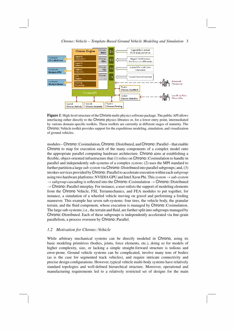
From an abstract perspective, Chrono rests on five foundation components thatprovide the following basic functionality: equation formulation, equation solution, collisiondetection and proximity computation, support for parallel computing, and pre/post-processing, see Fig. 1. The first foundation component, called “Equation Formulation”,supports general-purpose modeling for large systems of rigid and flexible bodies andfor basic fluid-solid interaction (FSI) problems. The second component, called “EquationSolution”, provides the algorithmic support needed to numerically solve the resultingequations of motion. Proximity computation support, essential for collision detectionand computation of short range interaction forces, is provided by the third foundationcomponent. The fourth component concentrates on parallel computing support at variouslevels: vectorization, acceleration using dedicated hardware (GPU), multi-core via OpenMP,and large scale as enabled by the MPI standard. Finally, the fifth component providespre- and post-processing support. For the latter, Chrono has run-time support via Irrlichtand OpenGL, and uses POV-Ray, Mitsuba, and ParaView for off-line, higher-quality,visualization.
One of Chrono’s strengths is its reliance on advanced computing hardware at variousstages of the solution process. Indeed, Chrono embraces cache friendly data structuressuitable for vectorization, and algorithms that expose parallelism at data and task levels.In a quest to reduce simulation times via parallel computing, we have established three
Chrono::Vehicle – Template-Based Ground Vehicle Modeling and Simulation 3
Figure 1: High-level structure of the Chrono multi-physics software package. The public API allowsinterfacing either directly to the Chrono physics libraries or, for a lower entry point, intermediatedby various domain-specific toolkits. These toolkits are currently at different stages of maturity. TheChrono::Vehicle toolkit provides support for the expeditious modeling, simulation, and visualizationof ground vehicles.
modules – Chrono::Cosimulation, Chrono::Distributed, and Chrono::Parallel – that enableChrono to map for execution each of the many components of a complex model ontothe appropriate parallel computing hardware architecture. Chrono aims at establishing aflexible, object-oriented infrastructure that (1) relies on Chrono::Cosimulation to handle inparallel and independently sub-systems of a complex system; (2) uses the MPI standard tofurther partition a large sub-system via Chrono::Distributed into parallel subgroups; and, (3)invokes services provided by Chrono::Parallel to accelerate execution within each subgroupusing two hardware platforms: NVIDIA GPU and Intel Xeon Phi. This system→ sub-system→ subgroup cascading is reflected into the Chrono::Cosimulation→Chrono::Distributed→Chrono::Parallel interplay. For instance, a user enlists the support of modeling elementsfrom the Chrono Vehicle, FSI, Terramechanics, and FEA modules to put together, forinstance, a simulation of a wheeled vehicle moving on gravel and performing a fordingmaneuver. This example has seven sub-systems: four tires, the vehicle body, the granularterrain, and the fluid component, whose execution is managed by Chrono::Cosimulation.The large sub-systems; i.e., the terrain and fluid, are further split into subgroups managed byChrono::Distributed. Each of these subgroups is independently accelerated via fine-grainparallelism, a process overseen by Chrono::Parallel.
1.2 Motivation for Chrono::Vehicle
While arbitrary mechanical systems can be directly modeled in Chrono, using itsbasic modeling primitives (bodies, joints, force elements, etc.), doing so for models ofhigher complexity, size, or lacking a simple straight-forward structure is tedious anderror-prone. Ground vehicle systems can be complicated, involve many tens of bodies(as is the case for segmented track vehicles), and require intricate connectivity andprecise design configurations. However, typical vehicle multi-body systems have relativelystandard topologies and well-defined hierarchical structure. Moreover, operational andmanufacturing requirements led to a relatively restricted set of designs for the main
4 author
vehicle sub-assemblies, such as suspensions, steering mechanism, track assemblies, etc. Asrecognized by most commercial multi-body dynamics software vendors [16, 23, 4] and bysome open-source multi-body simulation software developers, this suggests the design ofmodeling tools based on predefined parameterized templates for the major ground vehiclesubsystems. A template-based modeling capability thus enables the expeditious creation ofnew vehicles, allows rapid prototyping, and facilitates model re-use.
Chrono::Vehicle is the embodiment of this approach in the Chrono software suite. Itsmodular design, consistent API, rich set of templates, and organization of the simulationtime integration loop additionally enable easy replacement of various systems ("plug-and-play" philosophy) and seamless interfacing to third-party libraries. The architecture ofthe Chrono::Vehicle module allows both fully coupled and co-simulation approaches forvehicle-terrain simulations. In the latter case, the vehicle, terrain, engine, and driver systemsevolve in parallel with periodic data communication, for example in an explicit force–displacement co-simulation framework [21, 24].
In addition to providing Chrono users with the expected benefits of template-basedground vehicle modeling, Chrono::Vehicle was also architected and designed to leverageexisting and future extensions modeling capabilities in Chrono and capitalize on itsunderlying high-performance and parallel computing facilities. Chrono::Vehicle modelscan be easily incorporated in complex, multiphysics simulations, such as flexible tires ongranular terrain [21], fluid-solid interaction (FSI) fording scenarios [13], and autonomousand connected vehicle tests [3].
2 Template-based modeling
Chrono::Vehicle provides a collection of templates for various topologies of both wheeledand tracked vehicle subsystems, support for modeling rigid, flexible, and granular terrain,support for closed-loop and interactive driver models, and run-time and off-line visualizationof simulation results.
Modeling of vehicle systems is done in a modular fashion, with a vehicledefined as an assembly of instances of various subsystems (suspension, steering,driveline, etc.). Flexibility in modeling is provided by adopting a template-baseddesign. In Chrono::Vehicle, templates are parameterized models that define a particularimplementation of a vehicle subsystem. As such, a template defines the basic modelingelements (bodies, joints, force elements), imposes the subsystem topology, prescribes thedesign parameters, and implements the common functionality for a given type of subsystem(e.g., suspension) particularized to a specific template (e.g., double wishbone). Finally,an instantiation of such a template is obtained by specifying the template parameters(hardpoints, joint directions, inertial properties, contact material properties, etc.) for aconcrete vehicle (e.g., the HMMWV front suspension).
The core templates in Chrono::Vehicle are parameterized models of vehiclesubcomponents. However, a complete vehicle mobility simulation also requires auxiliarysystems, external to the vehicle itself, such as a driver system to provide input controls(e.g., steering, throttle, braking), a powertrain system which encapsulates the engine andtransmission and connects to the the vehicle driveline, and a terrain system.
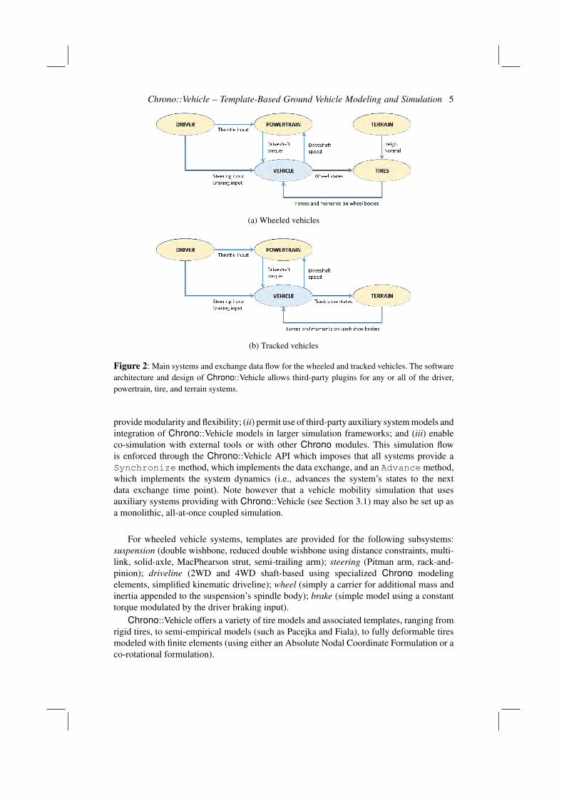
A Chrono::Vehicle simulation loop takes the form of a force-displacement co-simulation scheme, with the exchange data illustrated in Fig. 2a for wheeled vehiclesand Fig. 2b for tracked vehicles. This software architecture was adopted in order to (i)
Chrono::Vehicle – Template-Based Ground Vehicle Modeling and Simulation 5
(a) Wheeled vehicles
(b) Tracked vehicles
Figure 2: Main systems and exchange data flow for the wheeled and tracked vehicles. The softwarearchitecture and design of Chrono::Vehicle allows third-party plugins for any or all of the driver,powertrain, tire, and terrain systems.
provide modularity and flexibility; (ii) permit use of third-party auxiliary system models andintegration of Chrono::Vehicle models in larger simulation frameworks; and (iii) enableco-simulation with external tools or with other Chrono modules. This simulation flowis enforced through the Chrono::Vehicle API which imposes that all systems provide aSynchronize method, which implements the data exchange, and an Advance method,which implements the system dynamics (i.e., advances the system’s states to the nextdata exchange time point). Note however that a vehicle mobility simulation that usesauxiliary systems providing with Chrono::Vehicle (see Section 3.1) may also be set up asa monolithic, all-at-once coupled simulation.
For wheeled vehicle systems, templates are provided for the following subsystems:suspension (double wishbone, reduced double wishbone using distance constraints, multi-link, solid-axle, MacPhearson strut, semi-trailing arm); steering (Pitman arm, rack-and-pinion); driveline (2WD and 4WD shaft-based using specialized Chrono modelingelements, simplified kinematic driveline); wheel (simply a carrier for additional mass andinertia appended to the suspension’s spindle body); brake (simple model using a constanttorque modulated by the driver braking input).
Chrono::Vehicle offers a variety of tire models and associated templates, ranging fromrigid tires, to semi-empirical models (such as Pacejka and Fiala), to fully deformable tiresmodeled with finite elements (using either an Absolute Nodal Coordinate Formulation or aco-rotational formulation).
6 author
For tracked vehicles, the following subsystem templates are available: track shoe (single-and double-pin) and associated sprocket templates (with corresponding gear profiles),suspension (torsional spring with either linear or rotational damper, hydraulic), idler (withtensioner mechanism), and rollers.
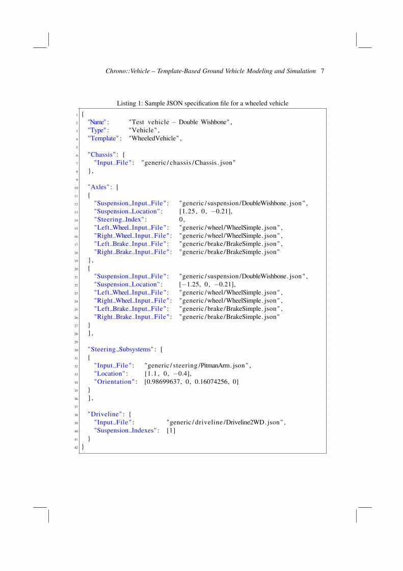
As a middleware library, Chrono::Vehicle requires the user to provide C++ classesfor a concrete instantiation of a particular template. An optional Chrono library providescomplete sets of such concrete C++ classes for a few ground vehicles, both wheeledand tracked, which can serve as examples for other specific vehicle models. While suchclasses are typically very lightweight, this requires some programming experience and,more importantly, makes it more difficult to encapsulate Chrono::Vehicle in a designexploration and virtual prototyping work-flow. To address this issue, we provide analternative mechanism for defining concrete instantiation of vehicle system and subsystemtemplates, which is based on input specification files in the JSON format [2]. Followingthe hierarchy of subsystem templates for its given type (wheeled or tracked), a vehiclecan be completely defined through a corresponding hierarchy of JSON files that specifythe concrete template parameters or else defer to further JSON specification files for sub-components. Listing 1 is an example of a top-level JSON specification file for a wheeledvehicle. Together with all other input files it refers to, this JSON file completely describes aconcrete wheeled vehicle with two axles, using double wishbone suspensions both in frontand rear, a Pitman arm steering mechanism attached to the front axle, and a rear-wheeldriveline.
3 Chrono::Vehicle templates and capabilities
In this section, we provide an overview of the system- and subsystem-level templatesavailable in Chrono::Vehicle.
Each vehicle subsystem is defined with respect to its own reference frame; in otherwords, all hardpoint locations in a vehicle subsystem template must be provided withrespect to the subsystem’s reference frame. A vehicle system, be it wheeled or tracked, isthen constructed as a collection of concrete instantiations of templates for its constituentcomponents by specifying their position and orientation with respect to the vehicle referenceframe and providing connectivity information, as required (e.g., attaching a particularsteering mechanism to a particular axle/suspension of a wheeled vehicle).
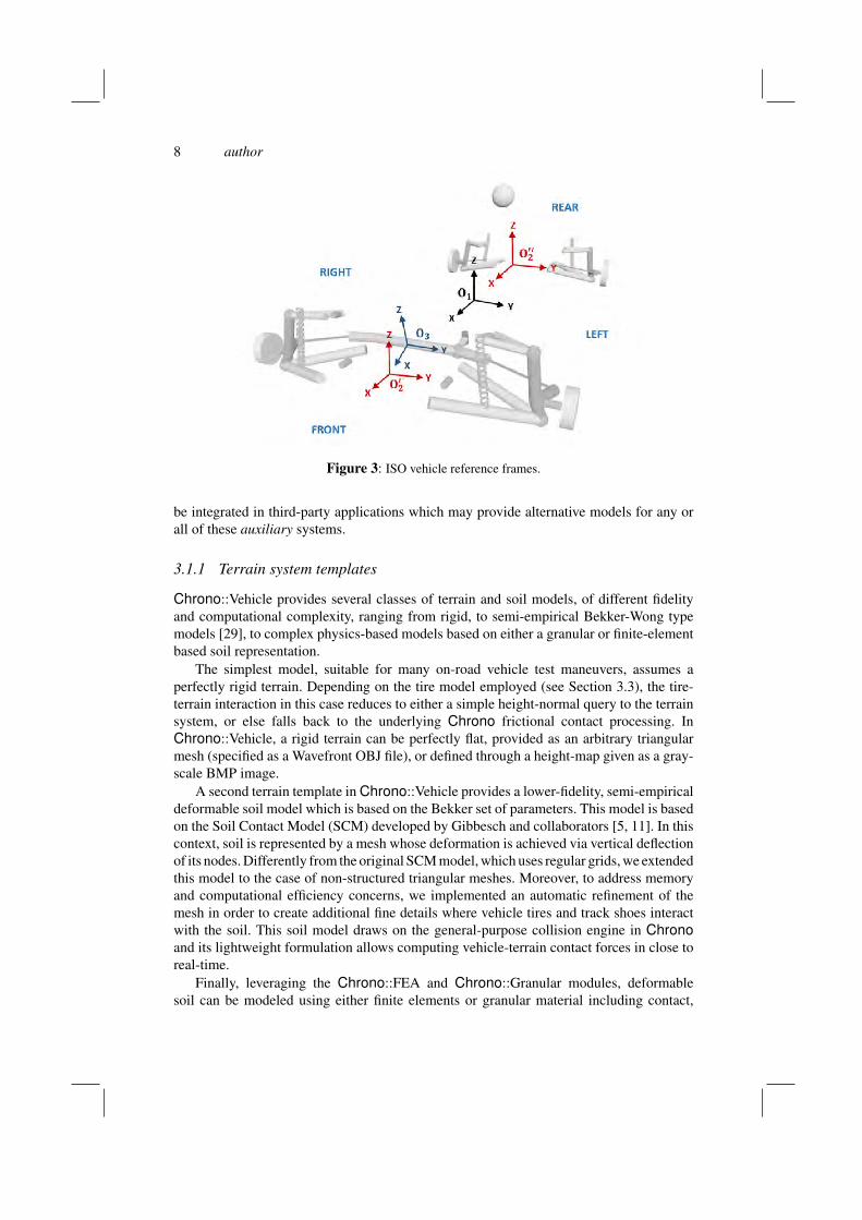
Chrono::Vehicle uses exclusively the ISO vehicle axes convention, namely a right-handframe with X forward, Z up, and Y pointing to the left of the vehicle (see ISO 8855:2011).Figure 3 illustrates the vehicle reference frame O1 (by convention aligned with that of thechassis subsystem), as well as subsystem reference frames (O′
2 and O′′2 for the front and
rear suspensions, and O3 for the steering mechanism) for a wheeled vehicle with two axles.
3.1 Common systems
We begin by describing the auxiliary systems, not part of the vehicle system itself, butrequired to set up a complete vehicle mobility simulation, namely the terrain, driver,and powertrain systems. For uniformity and modeling flexibility, these systems are alsotemplatized. Moreover, a consistent public API allows a Chrono::Vehicle vehicle model to
Chrono::Vehicle – Template-Based Ground Vehicle Modeling and Simulation 7
Listing 1: Sample JSON specification file for a wheeled vehicle
1 {2 "Name" : "Test vehicle − Double Wishbone" ,3 "Type" : "Vehicle" ,4 "Template" : "WheeledVehicle" ,5
6 "Chassis" : {7 "Input File" : "generic / chassis /Chassis . json"8 },9
10 "Axles" : [11 {12 "Suspension Input File" : "generic / suspension /DoubleWishbone. json" ,13 "Suspension Location" : [1.25 , 0, −0.21],14 "Steering Index" : 0,15 "Left Wheel Input File" : "generic /wheel/WheelSimple. json" ,16 "Right Wheel Input File" : "generic /wheel/WheelSimple. json" ,17 "Left Brake Input File" : "generic /brake /BrakeSimple . json" ,18 "Right Brake Input File" : "generic /brake /BrakeSimple . json"19 },20 {21 "Suspension Input File" : "generic / suspension /DoubleWishbone. json" ,22 "Suspension Location" : [−1.25, 0, −0.21],23 "Left Wheel Input File" : "generic /wheel/WheelSimple. json" ,24 "Right Wheel Input File" : "generic /wheel/WheelSimple. json" ,25 "Left Brake Input File" : "generic /brake /BrakeSimple . json" ,26 "Right Brake Input File" : "generic /brake /BrakeSimple . json"27 }28 ] ,29
30 "Steering Subsystems" : [31 {32 "Input File" : "generic / steering /PitmanArm. json" ,33 "Location" : [1.1 , 0, −0.4],34 "Orientation" : [0.98699637, 0, 0.16074256, 0]35 }36 ] ,37
38 "Driveline" : {39 "Input File" : "generic / driveline /Driveline2WD. json" ,40 "Suspension Indexes" : [1]41 }42 }
8 author
Figure 3: ISO vehicle reference frames.
be integrated in third-party applications which may provide alternative models for any orall of these auxiliary systems.
3.1.1 Terrain system templates
Chrono::Vehicle provides several classes of terrain and soil models, of different fidelityand computational complexity, ranging from rigid, to semi-empirical Bekker-Wong typemodels [29], to complex physics-based models based on either a granular or finite-elementbased soil representation.
The simplest model, suitable for many on-road vehicle test maneuvers, assumes aperfectly rigid terrain. Depending on the tire model employed (see Section 3.3), the tire-terrain interaction in this case reduces to either a simple height-normal query to the terrainsystem, or else falls back to the underlying Chrono frictional contact processing. InChrono::Vehicle, a rigid terrain can be perfectly flat, provided as an arbitrary triangularmesh (specified as a Wavefront OBJ file), or defined through a height-map given as a gray-scale BMP image.
A second terrain template in Chrono::Vehicle provides a lower-fidelity, semi-empiricaldeformable soil model which is based on the Bekker set of parameters. This model is basedon the Soil Contact Model (SCM) developed by Gibbesch and collaborators [5, 11]. In thiscontext, soil is represented by a mesh whose deformation is achieved via vertical deflectionof its nodes. Differently from the original SCM model, which uses regular grids, we extendedthis model to the case of non-structured triangular meshes. Moreover, to address memoryand computational efficiency concerns, we implemented an automatic refinement of themesh in order to create additional fine details where vehicle tires and track shoes interactwith the soil. This soil model draws on the general-purpose collision engine in Chronoand its lightweight formulation allows computing vehicle-terrain contact forces in close toreal-time.
Finally, leveraging the Chrono::FEA and Chrono::Granular modules, deformablesoil can be modeled using either finite elements or granular material including contact,
Chrono::Vehicle – Template-Based Ground Vehicle Modeling and Simulation 9
friction, and cohesion. The former uses a continuum soil model based on multiplicativeplasticity theory with Drucker-Prager failure criterion and a specialized 9-node brickelement which alleviates locking issues with standard 8-node FEA brick elements withoutthe need for numerical techniques such as enhanced assumed strain [32]. Physics-baseddeformable soil models based on granular dynamics simulations can be performed using theunderlying Chrono support for the Discrete Element Method (DEM). Unlike continuum-based deformable terrain modeling approaches, DEM treats all component particlesseparately, as distinct entities, by maintaining and advancing in time their states whiletaking into account pair-wise interaction forces due to frictional contact. Chrono::Vehiclesimulations on granular terrain can use either of the two methods supported in Chrono,namely a penalty-based, compliant-body approach, or a complementarity-based, rigid-body approach [27]. Since meaningful mobility simulations of vehicles on granular terraintypically result in DEM problems with millions of degrees of freedom, these are typicallyrun on parallel hardware, using either the Chrono::Parallel module for a coupled vehicle-terrain simulation [20], or else Chrono::Distributed in a co-simulation framework [21, 24].
3.1.2 Driver system templates
Driver inputs (steering, throttle, and braking) are provided from a driver subsystem withavailable options in ChronoVehicle including interactive, data-driven, and closed-loop (e.g.,path-following based on PID controllers).
The base C++ class for a driver system in Chrono::Vehicle imposes minimalrequirements from a driver system template, in particular the ability to return throttle input(normalized in the [0, 1] range), steering input (normalized in the [−1,+1] range, with anegative value indicating steering to the left), and braking input (normalized in the [0, 1]range). In addition, a driver system can receive information from any other system (e.g.,the vehicle state) through its Synchronize method and may have internal dynamics(implemented in its Advance method). Specific templates for a driver system may extendthe set of vehicle inputs generated, for example including the current selected gear for amanual transmission, enabling/disabling the cross-drive capability on a tracked vehicle, etc.
The Chrono::Vehicle library includes several templates for driver systems. Forinteractive simulations, run in soft real-time, we provide a template for a driver systemwhich produces the vehicle inputs based on user controls, either keyboard and mouse, or agame controller. For design of experiment simulations, we provide a driver system templatethat is based on inputs provided through a text data file, with the vehicle inputs obtainedthrough linear interpolation. Such data files can also be automatically generated by datacollected during interactive runs.
Finally, Chrono::Vehicle includes several closed-looped driver system models, basedon underlying support for PID controllers. These include speed controllers (which adjustthe throttle and braking input simultaneously to maintain a constant vehicle speed) andpath-follower controllers. The latter adjust the steering input so that the vehicle follows auser-defined path specified as a Bezier curve. A second type of closed-loop driver controllers,developed under the Chrono::CAVE module, provide vehicle inputs based on sensor data(LiDAR, GPS, IMU) for simulations involving connected and autonomous vehicles [3] andmodel-predictive controllers for obstacle-avoidance [8].
10 author
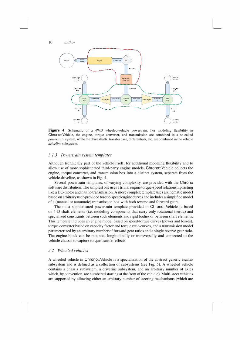
Figure 4: Schematic of a 4WD wheeled-vehicle powertrain. For modeling flexibility inChrono::Vehicle, the engine, torque converter, and transmission are combined in a so-calledpowertrain system, while the drive shafts, transfer case, differentials, etc. are combined in the vehicledriveline subsystem.
3.1.3 Powertrain system templates
Although technically part of the vehicle itself, for additional modeling flexibility and toallow use of more sophisticated third-party engine models, Chrono::Vehicle collects theengine, torque converter, and transmission box into a distinct system, separate from thevehicle driveline, as shown in Fig. 4.
Several powertrain templates, of varying complexity, are provided with the Chronosoftware distribution. The simplest one uses a trivial engine torque-speed relationship, actinglike a DC-motor and has no transmission. A more complex template uses a kinematic modelbased on arbitrary user-provided torque-speed engine curves and includes a simplified modelof a (manual or automatic) transmission box with both reverse and forward gears.
The most sophisticated powertrain template provided in Chrono::Vehicle is basedon 1-D shaft elements (i.e. modeling components that carry only rotational inertia) andspecialized constraints between such elements and rigid bodies or between shaft elements.This template includes an engine model based on speed-torque curves (power and losses),torque converter based on capacity factor and torque ratio curves, and a transmission modelparameterized by an arbitrary number of forward gear ratios and a single reverse gear ratio.The engine block can be mounted longitudinally or transversally and connected to thevehicle chassis to capture torque transfer effects.
3.2 Wheeled vehicles
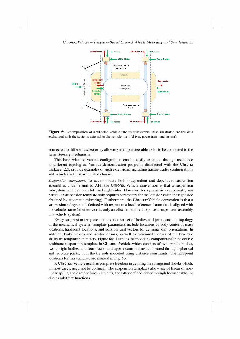
A wheeled vehicle in Chrono::Vehicle is a specialization of the abstract generic vehiclesubsystem and is defined as a collection of subsystems (see Fig. 5). A wheeled vehiclecontains a chassis subsystem, a driveline subsystem, and an arbitrary number of axleswhich, by convention, are numbered starting at the front of the vehicle). Multi-steer vehiclesare supported by allowing either an arbitrary number of steering mechanisms (which are
Chrono::Vehicle – Template-Based Ground Vehicle Modeling and Simulation 11
Figure 5: Decomposition of a wheeled vehicle into its subsystems. Also illustrated are the dataexchanged with the systems external to the vehicle itself (driver, powertrain, and terrain).
connected to different axles) or by allowing multiple steerable axles to be connected to thesame steering mechanism.
This base wheeled vehicle configuration can be easily extended through user codeto different topologies. Various demonstration programs distributed with the Chronopackage [22], provide examples of such extensions, including tractor-trailer configurationsand vehicles with an articulated chassis.
Suspension subsystem. To accommodate both independent and dependent suspensionassemblies under a unified API, the Chrono::Vehicle convention is that a suspensionsubsystem includes both left and right sides. However, for symmetric components, anyparticular suspension template only requires parameters for the left side (with the right sideobtained by automatic mirroring). Furthermore, the Chrono::Vehicle convention is that asuspension subsystem is defined with respect to a local reference frame that is aligned withthe vehicle frame (in other words, only an offset is required to place a suspension assemblyin a vehicle system).
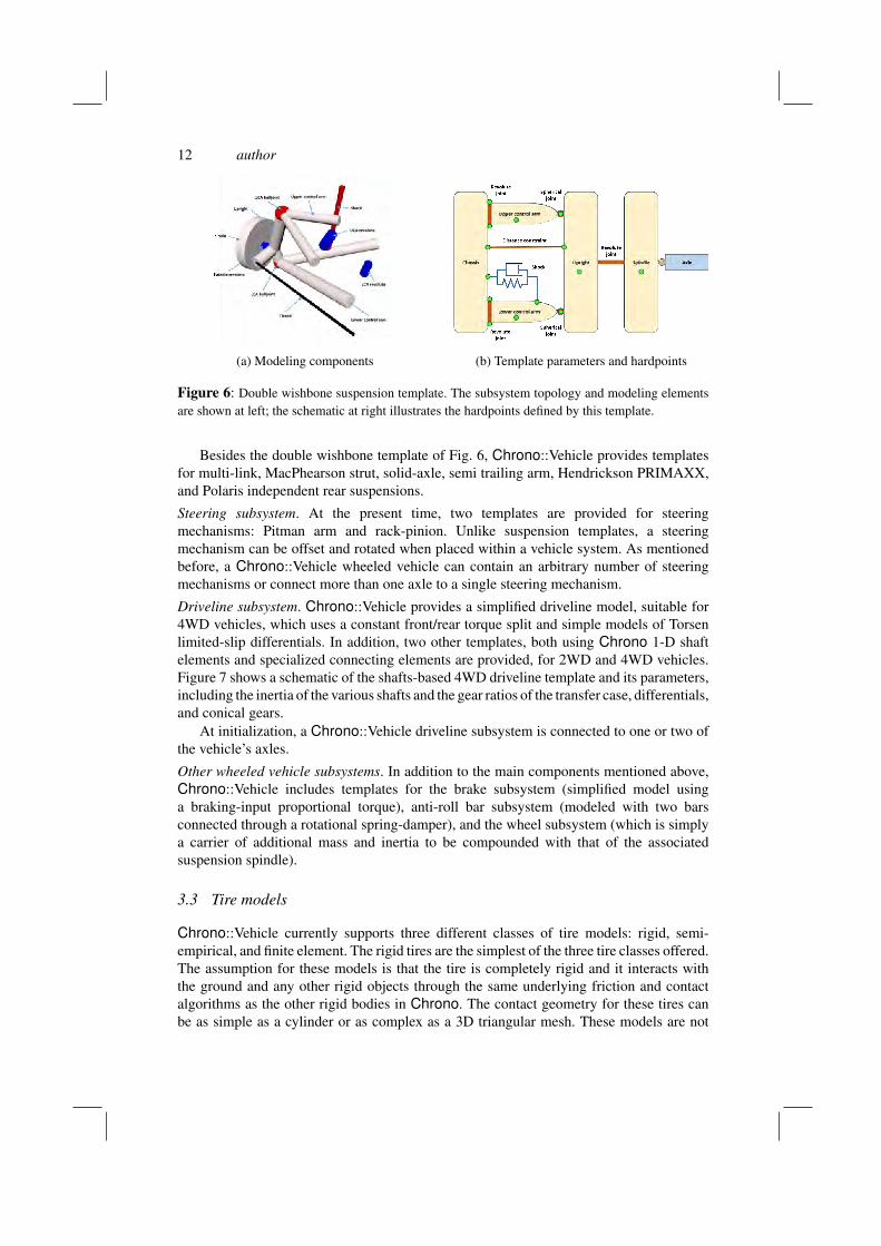
Every suspension template defines its own set of bodies and joints and the topologyof the mechanical system. Template parameters include locations of body center of masslocations, hardpoint locations, and possibly unit vectors for defining joint orientations. Inaddition, body masses and inertia tensors, as well as rotational inertias of the two axleshafts are template parameters. Figure 6a illustrates the modeling components for the doublewishbone suspension template in Chrono::Vehicle which consists of two spindle bodies,two upright bodies, and four (lower and upper) control arms, connected through sphericaland revolute joints, with the tie rods modeled using distance constraints. The hardpointlocations for this template are marked in Fig. 6b.
A Chrono::Vehicle user has complete freedom in defining the springs and shocks which,in most cases, need not be collinear. The suspension templates allow use of linear or non-linear spring and damper force elements, the latter defined either through lookup tables orelse as arbitrary functions.
12 author
(a) Modeling components (b) Template parameters and hardpoints
Figure 6: Double wishbone suspension template. The subsystem topology and modeling elementsare shown at left; the schematic at right illustrates the hardpoints defined by this template.
Besides the double wishbone template of Fig. 6, Chrono::Vehicle provides templatesfor multi-link, MacPhearson strut, solid-axle, semi trailing arm, Hendrickson PRIMAXX,and Polaris independent rear suspensions.
Steering subsystem. At the present time, two templates are provided for steeringmechanisms: Pitman arm and rack-pinion. Unlike suspension templates, a steeringmechanism can be offset and rotated when placed within a vehicle system. As mentionedbefore, a Chrono::Vehicle wheeled vehicle can contain an arbitrary number of steeringmechanisms or connect more than one axle to a single steering mechanism.
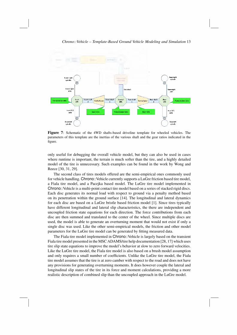
Driveline subsystem. Chrono::Vehicle provides a simplified driveline model, suitable for4WD vehicles, which uses a constant front/rear torque split and simple models of Torsenlimited-slip differentials. In addition, two other templates, both using Chrono 1-D shaftelements and specialized connecting elements are provided, for 2WD and 4WD vehicles.Figure 7 shows a schematic of the shafts-based 4WD driveline template and its parameters,including the inertia of the various shafts and the gear ratios of the transfer case, differentials,and conical gears.
At initialization, a Chrono::Vehicle driveline subsystem is connected to one or two ofthe vehicle’s axles.
Other wheeled vehicle subsystems. In addition to the main components mentioned above,Chrono::Vehicle includes templates for the brake subsystem (simplified model usinga braking-input proportional torque), anti-roll bar subsystem (modeled with two barsconnected through a rotational spring-damper), and the wheel subsystem (which is simplya carrier of additional mass and inertia to be compounded with that of the associatedsuspension spindle).
3.3 Tire models
Chrono::Vehicle currently supports three different classes of tire models: rigid, semi-empirical, and finite element. The rigid tires are the simplest of the three tire classes offered.The assumption for these models is that the tire is completely rigid and it interacts withthe ground and any other rigid objects through the same underlying friction and contactalgorithms as the other rigid bodies in Chrono. The contact geometry for these tires canbe as simple as a cylinder or as complex as a 3D triangular mesh. These models are not
Chrono::Vehicle – Template-Based Ground Vehicle Modeling and Simulation 13
Figure 7: Schematic of the 4WD shafts-based driveline template for wheeled vehicles. Theparameters of this template are the inertias of the various shaft and the gear ratios indicated in thefigure.
only useful for debugging the overall vehicle model, but they can also be used in caseswhere runtime is important, the terrain is much softer than the tire, and a highly detailedmodel of the tire is unnecessary. Such examples can be found in the work by Wong andReece [30, 31, 29].
The second class of tires models offered are the semi-empirical ones commonly usedfor vehicle handling. Chrono::Vehicle currently supports a LuGre friction based tire model,a Fiala tire model, and a Pacejka based model. The LuGre tire model implemented inChrono::Vehicle is a multi-point contact tire model based on a series of stacked rigid discs.Each disc generates its normal load with respect to ground via a penalty method basedon its penetration within the ground surface [14]. The longitudinal and lateral dynamicsfor each disc are based on a LuGre bristle based friction model [1]. Since tires typicallyhave different longitudinal and lateral slip characteristics, the there are independent anduncoupled friction state equations for each direction. The force contributions from eachdisc are then summed and translated to the center of the wheel. Since multiple discs areused, the model is able to generate an overturning moment that would not exist if only asingle disc was used. Like the other semi-empirical models, the friction and other modelparameters for the LuGre tire model can be generated by fitting measured data.
The Fiala tire model implemented in Chrono::Vehicle is largely based on the transientFiala tire model presented in the MSC ADAMS/tire help documentation [28, 17] which usestire slip state equations to improve the model’s behavior at slow to zero forward velocities.Like the LuGre tire model, the Fiala tire model is also based on a brush model assumptionand only requires a small number of coefficients. Unlike the LuGre tire model, the Fialatire model assumes that the tire is at zero camber with respect to the road and does not haveany provisions for generating overturning moments. It does however couple the lateral andlongitudinal slip states of the tire in its force and moment calculations, providing a morerealistic description of combined slip than the uncoupled approach in the LuGre model.
14 author
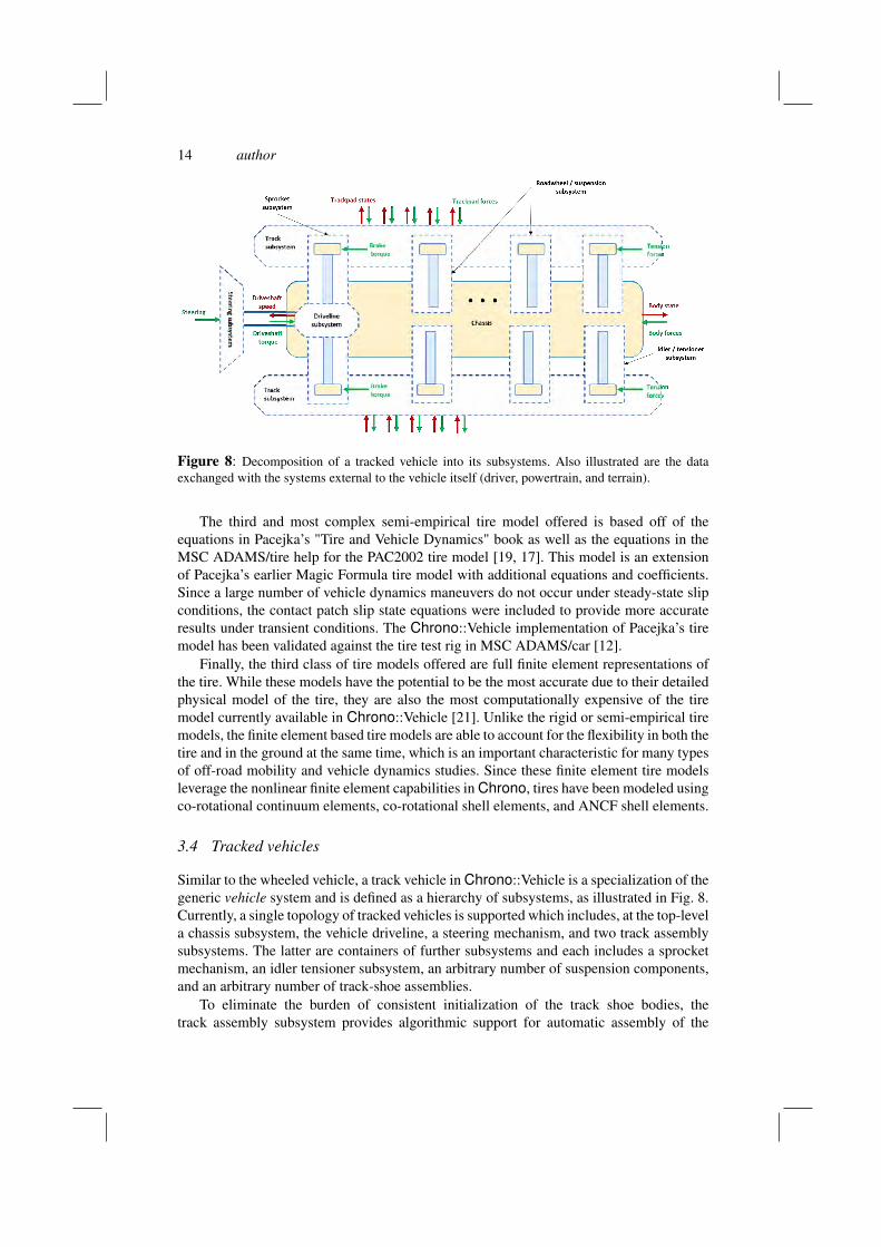
Figure 8: Decomposition of a tracked vehicle into its subsystems. Also illustrated are the dataexchanged with the systems external to the vehicle itself (driver, powertrain, and terrain).
The third and most complex semi-empirical tire model offered is based off of theequations in Pacejka’s "Tire and Vehicle Dynamics" book as well as the equations in theMSC ADAMS/tire help for the PAC2002 tire model [19, 17]. This model is an extensionof Pacejka’s earlier Magic Formula tire model with additional equations and coefficients.Since a large number of vehicle dynamics maneuvers do not occur under steady-state slipconditions, the contact patch slip state equations were included to provide more accurateresults under transient conditions. The Chrono::Vehicle implementation of Pacejka’s tiremodel has been validated against the tire test rig in MSC ADAMS/car [12].
Finally, the third class of tire models offered are full finite element representations ofthe tire. While these models have the potential to be the most accurate due to their detailedphysical model of the tire, they are also the most computationally expensive of the tiremodel currently available in Chrono::Vehicle [21]. Unlike the rigid or semi-empirical tiremodels, the finite element based tire models are able to account for the flexibility in both thetire and in the ground at the same time, which is an important characteristic for many typesof off-road mobility and vehicle dynamics studies. Since these finite element tire modelsleverage the nonlinear finite element capabilities in Chrono, tires have been modeled usingco-rotational continuum elements, co-rotational shell elements, and ANCF shell elements.
3.4 Tracked vehicles
Similar to the wheeled vehicle, a track vehicle in Chrono::Vehicle is a specialization of thegeneric vehicle system and is defined as a hierarchy of subsystems, as illustrated in Fig. 8.Currently, a single topology of tracked vehicles is supported which includes, at the top-levela chassis subsystem, the vehicle driveline, a steering mechanism, and two track assemblysubsystems. The latter are containers of further subsystems and each includes a sprocketmechanism, an idler tensioner subsystem, an arbitrary number of suspension components,and an arbitrary number of track-shoe assemblies.
To eliminate the burden of consistent initialization of the track shoe bodies, thetrack assembly subsystem provides algorithmic support for automatic assembly of the
Chrono::Vehicle – Template-Based Ground Vehicle Modeling and Simulation 15
track around the sprocket, idler, road-wheels, and any existing rollers. Specialized trackassemblies and corresponding assembly routines are provided for different combinationsof sprocket profiles and associated track shoe models.
A salient feature of tracked vehicles, which differentiates them from wheeled vehicles, isthe important role played by contacts between internal components. While contact betweentrack shoe bodies and the track wheels can be directly supported by the underlying frictionalcontact algorithms in Chrono, the sprocket-track shoe contact, involving complex andnon-convex profiles, requires special treatment. In Chrono::Vehicle, sprocket profiles aredefined as 2D curves (parameterized differently for sprockets engaging single- and double-pin track shoes) and the sprocket-track shoe contact is processed with a custom collisiondetection algorithm.
Track-shoe subsystem. Chrono::Vehicle offers templates for both single-pin and double-pintrack shoes, each of which can have central or lateral guiding pins. The single-pin trackshoe consists of a single body with non-trivial contact geometry which is connected to itsneighbors through revolute joints. The double-pin track shoe template contains, in additionto the main track pad body, two additional connector bodies which are connected throughrevolute joints to the adjacent pads and which carry the contact geometry for collision withthe track’s sprocket gears.
All track shoe templates are fully parameterized in terms of dimensions, masses andinertias of the constituent bodies, as well as their contact geometry.
Sprocket subsystem. The sprocket subsystem connects the tracked vehicle driveline tothe track assembly and is responsible for collision detection and contact processing withthe track shoe bodies. A sprocket subsystem template implements the custom collisiondetection algorithm for a consistent pair of sprocket gear profile and associated track shoe.Chrono::Vehicle provides two templates for the sprocket subsystem, corresponding to thetwo types of supported track shoes, namely single-pin and double-pin. The sprocket gearprofile is defined as a 2D path composed of line segments and circular arcs which areparameterized for each type of profile. Collision detection is performed in 2D, working inthe plane of the sprocket gear, but contact forces are calculated in 3D before being appliedto the sprocket and interacting track shoe bodies.
In addition to the gear profile, a sprocket template is parameterized by the mass andinertia of the sprocket body, the rotational inertia of the sprocket axle, and the separationdistance between the two gears.
Suspension templates. Different suspension configurations are available, including torsionspring with linear or rotational dampers and a hydropneumatic suspension template. Atrack assembly can contain an arbitrary number of suspension subsystems which, for thetemplates using a torsion spring, may or may not include a damper. A Chrono::Vehiclesuspension subsystem also contains a road-wheel, themselves templatized based on the typeof track shoe used (central or lateral guiding pins).
Similar to the case of wheeled vehicle, a tracked vehicle suspension template allowscomplete freedom in specifying spring and damper forces which can be linear or non-linear,defined through table lookup or implemented in user-provided C++ functions.
Idler subsystem. A Chrono::Vehicle idler mechanism consists of the idler wheel and aconnecting body. The idler wheel is connected through a revolute joint to the connectingbody which in turn is connected to the chassis through a translational joint. A linear actuatoracts as a tensioner which is modeled as a general spring-damper with optional preload. Anidler subsystem is defined with respect to a frame centered at the origin of the idler wheel,
16 author
optionally pitched relative to the chassis reference frame. The translational joint is alignedwith the X axis of this reference frame, while the axis of rotation of the revolute joint isaligned with its Y axis.
Like the road-wheels, different templates are provided for the case of tracks with centralor lateral guiding pins.
3.5 Visualization and post-processing
Chrono::Vehicle provides visualization support both for run-time interactive simulations, aswell as for high-quality post-processing rendering for generating animations. Currently, run-time simulation support expands on the underlying Chrono::Irrlicht module for sequentialsimulations [9] or the more computationally efficient but more limited Chrono::OpenGLmodule for parallel simulations involving large-scale granular terrain representations [10].Ongoing development effort involves a transition to an Ogre-based run-time visualizationsystem [15], as a replacement for Chrono::Irrlicht. Support for ray-traced renderings ofindividual simulation frames is offered through utility functions that can be called fromwithin the simulation loop to export data files with current visualization assets informationand a POV-Ray script [18] that can batch-process these files to generate frame images.
Extraction of simulation results at vehicle-, subsystem-, or model component-level iscurrently limited to using the Chrono::Vehicle C++ API which provides an exhaustive set ofmethods for this purpose, as well as utility for data filtering, I/O, etc. A specialized moduleis currently under development to provide a formal mechanism for extracting a list of allavailable output channels and metrics of interest from a vehicle simulation, automatic datacollection during the simulation, and final reporting and plotting of user-specified quantitiesof interest.
4 Ground vehicle mobility simulations with Chrono::Vehicle
Chrono::Vehicle has been used extensively in many ground vehicle mobility studies, bothat the University of Wisconsin - Madison, by our external collaborators, and by externalChrono users. Some typical simulations, involving both wheeled and tracked vehicles, areillustrated in Fig. 9.
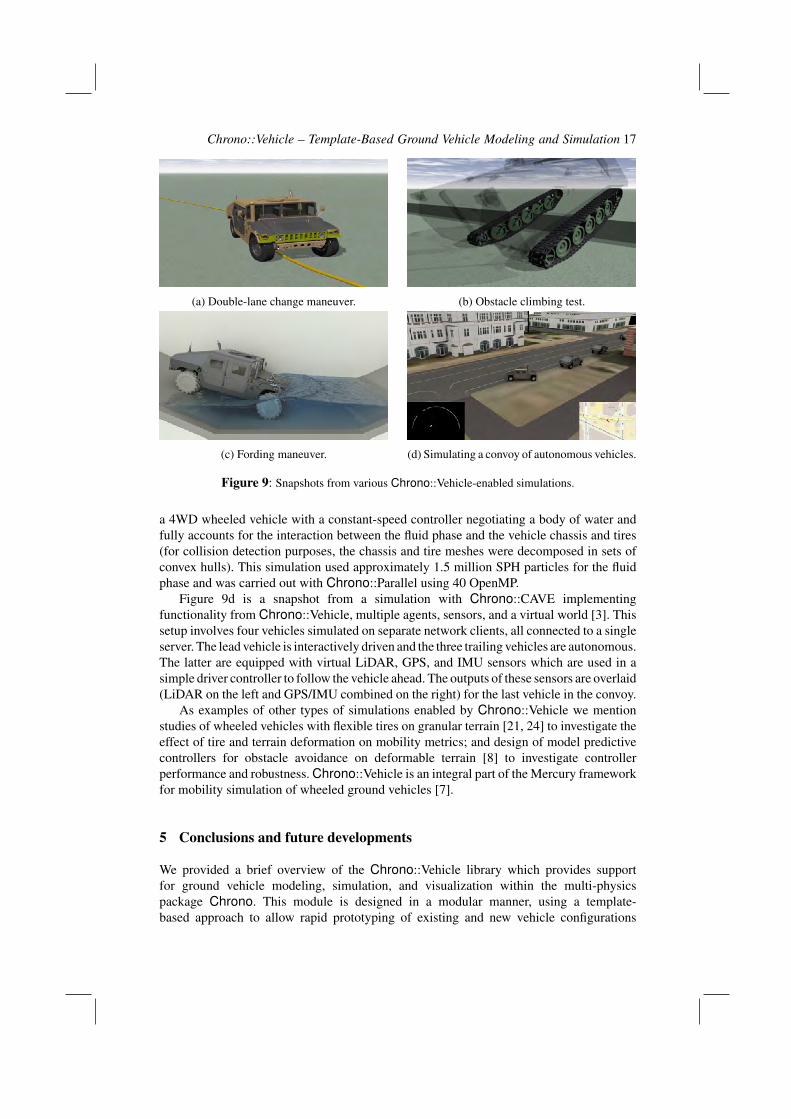
The simulation snapshot in Fig. 9a is an example of a standard mobility test on rigid flatterrain. The double lane change in this demonstration used a 4WD wheeled vehicle withFiala tire models and a path-follower driver system with a constant-speed controller. Therelevant mobility metrics extracted from such a simulation include the maximum speed atwhich the maneuver can be safely performed, accelerations at the driver location, and thevehicle inputs generated by the closed-loop driver system.
Figure 9b is a snapshot from a step-climbing validation test for determining themaximum obstacle height that can be managed by a tracked vehicle from rest. The vehicleused in this test contains over 150 bodies and is modeled with single-pin track shoes andlinear-damper suspensions.
In conjunction with the Chrono::FSI module, Chrono::Vehicle has been used in fluid-solid interaction problems to simulate fording maneuvers and sloshing of liquids in vehicle-mounted tanks [13]. These simulations capture the two-way coupling between the vehicledynamics and the fluid phase, the latter being governed by the mass and momentum (Navier-Stokes) equations discretized in space via SPH. The simulation illustrated in Fig. 9c involved
Chrono::Vehicle – Template-Based Ground Vehicle Modeling and Simulation 17
(a) Double-lane change maneuver. (b) Obstacle climbing test.
(c) Fording maneuver. (d) Simulating a convoy of autonomous vehicles.
Figure 9: Snapshots from various Chrono::Vehicle-enabled simulations.
a 4WD wheeled vehicle with a constant-speed controller negotiating a body of water andfully accounts for the interaction between the fluid phase and the vehicle chassis and tires(for collision detection purposes, the chassis and tire meshes were decomposed in sets ofconvex hulls). This simulation used approximately 1.5 million SPH particles for the fluidphase and was carried out with Chrono::Parallel using 40 OpenMP.
Figure 9d is a snapshot from a simulation with Chrono::CAVE implementingfunctionality from Chrono::Vehicle, multiple agents, sensors, and a virtual world [3]. Thissetup involves four vehicles simulated on separate network clients, all connected to a singleserver. The lead vehicle is interactively driven and the three trailing vehicles are autonomous.The latter are equipped with virtual LiDAR, GPS, and IMU sensors which are used in asimple driver controller to follow the vehicle ahead. The outputs of these sensors are overlaid(LiDAR on the left and GPS/IMU combined on the right) for the last vehicle in the convoy.
As examples of other types of simulations enabled by Chrono::Vehicle we mentionstudies of wheeled vehicles with flexible tires on granular terrain [21, 24] to investigate theeffect of tire and terrain deformation on mobility metrics; and design of model predictivecontrollers for obstacle avoidance on deformable terrain [8] to investigate controllerperformance and robustness. Chrono::Vehicle is an integral part of the Mercury frameworkfor mobility simulation of wheeled ground vehicles [7].
5 Conclusions and future developments
We provided a brief overview of the Chrono::Vehicle library which provides supportfor ground vehicle modeling, simulation, and visualization within the multi-physicspackage Chrono. This module is designed in a modular manner, using a template-based approach to allow rapid prototyping of existing and new vehicle configurations
18 author
and to facilitate its integration in third-party simulation frameworks. The simulation loopin Chrono::Vehicle is structured such that it permits both monolithic coupled vehiclesimulations and co-simulation for large-scale vehicle–terrain–environment multi-physicsand multi-scale simulation.
Current and planned development involves inclusion of additional subsystem templates,such as support for continuous rubber band tracked vehicles, as well as new capabilities,primarily related to formalization of data collection, output of mobility metrics, and post-processing.
Complex vehicle–terrain simulations, particularly those involving high-fidelity FEA-based flexible tires, granular terrain, and multi-phase FSI problems, continue to pose seriouschallenges, including the still considerable computational requirements. Plans for futureresearch and development in this area focus on leveraging hybrid parallel computing asenabled by the interplay of Chrono::Distributed and Chrono::Parallel in a co-simulationframework.
References
[1] N. B. Do, A. A. Ferri, and O. A. Bauchau. Efficient simulation of a dynamic systemwith lugre friction. Journal of Computational and Nonlinear Dynamics, 2(4):281–289,2007.
[2] ECMA. The JSON data interchange format. Technical Report ECMA-404, ECMAInternational, 2013.
[3] A. Elmquist, D. Hatch, C. Ricchio, R. Serban, and D. Negrut. Virtual autonomousvehicle testing via a Connected Autonomous Vehicle Emulator (CAVE). InJ. Michopoulos, D. Rosen, C. Paredis, and J. Vance, editors, Advances in Computersand Information in Engineering Research. ASME Press, New York, 2017.
[4] FunctionBay. Recurdyn. http://eng.functionbay.co.kr. Accessed: 2015-02-07.
[5] A. Gibbesch and B. Schafer. Multibody system modelling and simulation of planetaryrover mobility on soft terrain. In 8th International Symposium on Artificial Intelligence,Robotics and Automation in Space (i-SAIRAS 2005), Munich, Germany, September,pages 5–8, 2005.
[6] R. A. Gingold and J. J. Monaghan. Kernel estimates as a basis for general particlemethods in hydrodynamics. Journal of Computational Physics, 46(3):429–453, 1982.
[7] C. Goodin, J. Mange, S. Pace, T. Skorupa, D. Kedziorek, J. Priddy, and L. Lynch.Simulating the mobility of wheeled ground vehicles with mercury. SAE Int. J. Commer.Veh., 10(2), 2017.
[8] N. Haraus, R. Serban, and J. Fleischmann. Performance analysis of constant speedlocal obstacle avoidance controller using an MPC algorithm on granular terrain. InGround Vehicle Systems Engineering and Technology Symposium, 2017.
[9] Irrlicht. Open Source 3D Irrlicht Engine. http://irrlicht.sourceforge.net/, 2014.
Chrono::Vehicle – Template-Based Ground Vehicle Modeling and Simulation 19
[10] Khronos Group. Open Graphics Library - OpenGL. http://www.opengl.org/,2014.
[11] R. Krenn and A. Gibbesch. Soft soil contact modeling technique for multi-body systemsimulation. In Trends in computational contact mechanics, pages 135–155. Springer,2011.
[12] J. Madsen. Validation of a Single Contact Point Tire Model Based on theTransient Pacejka Model in the Open-Source Dynamics Software Chrono. TechnicalReport TR-2014-16: http://sbel.wisc.edu/documents/TR-2014-16.pdf, Simulation-Based Engineering Laboratory, University of Wisconsin-Madison,2014.
[13] H. Mazhar, A. Pazouki, M. Rakhsha, P. Jayakumar, and D. Negrut. A differentialvariational approach for handling fluid-solid interaction problems via SmoothedParticle Hydrodynamics. Journal of Computational Physics (under review), 0:0, 2017.
[14] A. Mikkola. Lugre Tire Model for HMMWV. Technical Report TR-2014-15: http://sbel.wisc.edu/documents/TR-2014-15.pdf, Simulation-Based Engineering Laboratory, University of Wisconsin-Madison, 2014.
[15] I. Milne and G. Rowe. OGRE-3D program visualization for C++. In Proceedings ofthe 3rd Annual LTSN-ICS Conference, 2002.
[16] MSC Software. ADAMS. http://www.mscsoftware.com/product/adams. Accessed: 2015-02-07.
[17] MSC Software. ADAMS/Tire help - ADAMS 2015. https://simcompanion.mscsoftware.com/infocenter/index?page=content&id=DOC10813&cat=2015_ADAMS_DOCS&actp=LIST/, July 2015.
[18] Persistence of Vision Pty. Ltd. Persistence of Vision (TM) Raytracer. http://www.povray.org, 2004.
[19] H. B. Pacejka. Tire and vehicle dynamics. Elsevier, 2005.
[20] A. Pazouki, M. Kwarta, K. Williams, W. Likos, R. Serban, J. Jayakumar, and D. Negrut.Compliant versus rigid contact – a comparison in the context of granular dynamics.Phys. Rev. E (under review), 0:0, 2017.
[21] A. M. Recuero, R. Serban, B. Peterson, H. Sugiyama, P. Jayakumar, and D. Negrut. Ahigh-fidelity approach for vehicle mobility simulation: Nonlinear finite element tiresoperating on granular material. Journal of Terramechanics, 72:39 – 54, 2017.
[22] Project Chrono Development Team. Chrono: An Open Source Framework forthe Physics-Based Simulation of Dynamic Systems. https://github.com/projectchrono/chrono. Accessed: 2017-05-07.
[23] Siemens PLM Software. Siemens Virtual.Lab. https://www.plm.automation.siemens.com/en_us/products/lms/virtual-lab/.Accessed: 2016-09-13.
20 author
[24] R. Serban, N. Olsen, D. Negrut, A. M. Recuero, and P. Jayakumar. A co-simulationframework for high-performance, high-fidelity simulation of ground vehicle-terraininteraction. In AVT-265: Integrated Virtual NATO Vehicle Development, Vilnius,Lithuania, May 2017.
[25] A. A. Shabana and R. Y. Yakoub. Three dimensional absolute nodal coordinateformulation for beam elements: Theory. ASME Journal of Mechanical Design,123:606–613, 2001.
[26] J. C. Simo and L. Vu-Quoc. Three-dimensional finite-strain rod model. part ii:Computational aspects. Computer Methods in Applied Mechanics and Engineering,58:79–116, 1986.
[27] A. Tasora, R. Serban, H. Mazhar, A. Pazouki, D. Melanz, J. Fleischmann, M. Taylor,H. Sugiyama, and D. Negrut. Chrono: An open source multi-physics dynamics engine.In T. Kozubek, editor, High Performance Computing in Science and Engineering –Lecture Notes in Computer Science, pages 19–49. Springer, 2016.
[28] M. Taylor. Implementation and validation of the Fiala tire model in Chrono. TechnicalReport TR-2015-13: http://sbel.wisc.edu/documents/TR-2016-06.pdf, University of Wisconsin–Madison, 2015.
[29] J. Y. Wong. Theory of Ground Vehicles. John Wiley & Sons, New York, 2001.
[30] J. Y. Wong and A. R. Reece. Prediction of rigid wheel performance based on theanalysis of soil-wheel stresses part i. performance of driven rigid wheels. Journal ofTerramechanics, 4(1):81–98, 1967.
[31] J. Y. Wong and A. R. Reece. Prediction of rigid wheel performance based on theanalysis of soil-wheel stresses: Part ii. performance of towed rigid wheels. Journal ofTerramechanics, 4(2):7–25, 1967.
[32] H. Yamashita, P. Jayakumar, and H. Sugiyama. Modeling of deformable tire andsoil interaction using multiplicative finite plasticity for multibody off-road mobilitysimulation. In Proceedings of the ASME 2016 International Design EngineeringTechnical Conferences and Computers and Information in Engineering ConferenceIDETC/CIE 2016, 2016.