Embed Size (px)
Citation preview

Computer Science
Bachelor’s Project
2001:13
Christoffer Branzell
Bernhard Eriksson
SUA on SCTP
Connecting the Telecommunication Networks to the IP Networks


© 2001 The authors and Karlstad University
SUA on SCTP
Connecting the Telecommunication Networks to the IP Networks
Christoffer Branzell
Bernhard Eriksson


iii
This report is submitted in partial fulfillment of the requirements for the
Bachelor’s degree in Computer Science. All material in this report which is
not my own work has been identified and no material is included for which
a degree has previously been conferred.
Christoffer Branzell
Bernhard Eriksson
Approved, 2001-06-05
Advisor: Eivind J. Nordby
Examiner: Stefan Lindskog


v
Abstract
This document describes the evaluation and prototyping of a subset of the IETF SUA draft 05.
The intended readers of this document are developers within the SS7 and IP environments.
SUA is an adaptation layer designed, together with SCTP, to partially emulate SCCP. This
enables already existing applications and application layers to be moved from the SS7 domain
to the IP domain. The focus of this project is on the connectionless parts of SUA, the
connection-oriented parts are omitted. Furthermore the document describes the environments,
the IP domain and the SS7 domain, within the framework of which SUA works and the stack
layers, SCCP and SCTP, that SUA communicates with. Also described are the design choices
we made regarding the functions, modules and the complete prototype with explanations
about why we choose the particular design solutions. The implementation and testing, as well
as the design, are described in increasing steps. Our results, from the implementation, indicate
that at least the connectionless parts of the SUA-draft are stabile enough to become a
proposed standard.

vi
Acknowledgements
First we would like to thank our supervisors at Ericsson Infotech, Sören Torstensson and
Mikael Blom, and our supervisor at Karlstad University, Eivind J. Nordby, for their help with
the technical and administrative work during this project. Further on we would like to thank
Anders Ellström and Robert Nilsson at Ericsson Infotech for their advise during the work.
Finally we would like to thank Robin Thunell at Ericsson Infotech for his help with SCTP.
Karlstad the 11th of June 2001
Christoffer Branzell
Bernhard Eriksson

vii
Contents
1 Introduction .......................................................................................................................11.1 Why this project has been commissioned ..................................................................1
1.2 Objectives of the project work ...................................................................................1
1.3 The scope of the work ................................................................................................2
1.4 The structure of the report..........................................................................................2
2 Background........................................................................................................................32.1 Why use SUA.............................................................................................................3
2.2 Signaling within telecommunication networks..........................................................3
2.3 SS7 - Signaling System number 7..............................................................................3
2.4 SCTP - Stream Control Transmission Protocol .........................................................4
2.5 Addressing Space .......................................................................................................5
3 SUA - SCCP User Adaptation Layer...............................................................................53.1 SUA draft ...................................................................................................................5
3.2 IP-IP architecture .......................................................................................................5
3.3 Interconnection of the SS7 domain and the IP domain..............................................6
4 Design..................................................................................................................................74.1 General design............................................................................................................7
4.1.1 Services provided by SUA4.1.2 Ericsson Common Parts4.1.3 Naming conventions for inter-layer communication4.1.4 API considerations4.1.5 State event matrix implementation4.1.6 The addressing issue4.1.7 Test cases4.1.8 SCTP “snapshot”4.1.9 Supplied foundation
4.2 SUA..........................................................................................................................124.2.1 Subset definition4.2.2 General design issues4.2.3 Modular design
4.3 SG.............................................................................................................................15
5 Implementation and test .................................................................................................155.1 Functions..................................................................................................................15
5.2 Modules....................................................................................................................165.2.1 Common implementation solutions5.2.2 SUA_main5.2.3 SUA5.2.4 SCTP5.2.5 SCCP

viii
5.3 Prototype ..................................................................................................................19
6 General problems ............................................................................................................206.1 Problems encountered with the SUA-draft ..............................................................20
6.2 Administrative problems..........................................................................................21
6.3 Technical problems ..................................................................................................21
6.4 SCTP problems ........................................................................................................22
7 Results...............................................................................................................................22
8 Conclusions ......................................................................................................................23
References................................................................................................................................24
A Acronyms and abbreviations..........................................................................................25
B Development environment ..............................................................................................26
C SUA Message Classes and Types....................................................................................27
D Supported SCCP PDU Primitives ..................................................................................29

ix
List of Figures
Figure 1.1: Simple description of the connection between the IP and SS7 domains ..........2
Figure 2.1: SS7-SS7 domain ...............................................................................................4
Figure 3.1: IP-IP domain .....................................................................................................6
Figure 3.2: Interconnection of the SS7 and IP domains ......................................................7
Figure 4.1: Services provided by SUA................................................................................8
Figure 4.2: Communication trough Common Parts ............................................................9
Figure 4.3: Inter-layer communication naming conventions ............................................10
Figure 4.4: SUA/SCTP SCCP exchangeability.................................................................11
Figure 4.5: SUA state event graph ....................................................................................13
Figure 4.6: Modular design of SUA ..................................................................................14
Figure 5.1: Function testing approach ...............................................................................15
Figure 5.2: Using a state event matrix (array) ...................................................................16
Figure 5.3: Communication between SUA_main and the SCTP and SCCP modules ......17
Figure 5.4: SUA message format ......................................................................................17
Figure 5.5: SUA: message path in module test case..........................................................18
Figure 5.6: SUA: sequence of heartbeat message .............................................................18
Figure 5.7: SCTP: module test case message path, using a gateway function. .................19
Figure 5.8: Prototype: test case message path ..................................................................20

x
List of tables
Table 4.1: SCCP/SUA message classes ............................................................................12
Table C.1 SUA Management Messages ............................................................................27
Table C.2 SS7 Signaling Network Management...............................................................27
Table C.3 Application Server Process Maintenance .........................................................27
Table C.4 ASP Traffic Maintenance Messages.................................................................28
Table C.5 Connectionless Messages .................................................................................28
Table C.6 Connection-Oriented Messages ........................................................................28
Table D.7: SCCP Primitives..............................................................................................29

1
1 Introduction
This is the report of a bachelor’s project commissioned by Ericsson Infotech (EIN/N)
Karlstad, during the spring 2001. The authors of this report are two undergraduate students
from the Computer Science department at Karlstad University. The work described in this
report is our bachelor project. This chapter presents the background and the focus for the
work and concludes with a presentation of the structure for the rest of the report.
1.1 Why this project has been commissioned
Due to the increasing availability of IP-networks, a possibility to use these networks to
transport signaling data has arisen. Partly because of this, methods to connect the Signaling
System number 7 (SS7) domain to the IP domain have been created. This project centers on
one of the solutions that are being developed to bridge between these two domains.
Ericsson has, as one of the top companies in the telecommunication area, decided to
evaluate the fifth draft[1] of an adaptation layer called “SCCP User Adaptation layer” (SUA).
SUA allows SS7 applications and application layers to work within the IP domain, and to
communicate between the SS7 domain and the IP domain. This has lead to the commissioning
of the project by the signaling department (EIN/N) at Ericsson Infotech AB in Karlstad.
1.2 Objectives of the project work
The main objective of this project work is to prototype the SUA-draft. If time permits, we
should also try to use the SUA prototype with a Signaling Gateway (SG), that we also need to
implement, to send signaling data between the IP and SS7 domains. The role of the SG in
relation to SS7 and IP networks is shown in Figure 1.1. Note that in Figure 1.1 SCCP and
SUA are network layers and not complete applications. The SG translates the SCCP and SUA
messages and thus connects the two domains.

2
SS7IPSGSCC
P
SUA
Figure 1.1: Simple description of the connection between the IP and SS7 domains
One objective of our project is also to describe the problems we have encountered during
the project work and the possible problems that may be encountered during an
implementation of this draft. Additionally we expect to gather more experience about
programming in a corporate environment during the project.
1.3 The scope of the work
The task of implementing all functionality in SUA is not possible within the time frame for
the project. Because of this, only the simplest method of communication, connectionless
communication, is included. Appendix D includes the SCCP primitives that are supported.
The previously mentioned SG is also part of the SUA-draft. If it can be done within the
time frame, we will try to implement some of the functionality in the SG. The functionality
we intend to implement in the SG is the ability to send connectionless messages between the
IP domain and the SS7 domain.
1.4 The structure of the report
This report has the following structure. Chapter 2 includes a brief description of the different
domains that the SUA layer will communicate with and the main transport protocols that will
be used. The SUA layer, and its possible usage, is described in Chapter 3.
Chapter 4 describes how we designed the SUA layer prototype and possibly the SG and
what parts of the draft we chose to implement. Chapter 5 describes the implementation
process and the testing we did when we implemented the prototype we designed in previous
chapter. Further on Chapter B contains a description of the environment we worked in when
we developed and compiled the prototype.
Chapter 6 describes the various problems we encountered during the project. Chapter 7
describes the results we achieved and Chapter 8 contains the conclusions we have drawn
during the project.
3
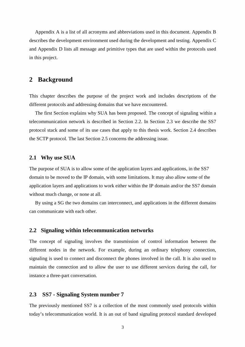
Appendix A is a list of all acronyms and abbreviations used in this document. Appendix B
describes the development environment used during the development and testing. Appendix C
and Appendix D lists all message and primitive types that are used within the protocols used
in this project.
2 Background
This chapter describes the purpose of the project work and includes descriptions of the
different protocols and addressing domains that we have encountered.
The first Section explains why SUA has been proposed. The concept of signaling within a
telecommunication network is described in Section 2.2. In Section 2.3 we describe the SS7
protocol stack and some of its use cases that apply to this thesis work. Section 2.4 describes
the SCTP protocol. The last Section 2.5 concerns the addressing issue.
2.1 Why use SUA
The purpose of SUA is to allow some of the application layers and applications, in the SS7
domain to be moved to the IP domain, with some limitations. It may also allow some of the
application layers and applications to work either within the IP domain and/or the SS7 domain
without much change, or none at all.
By using a SG the two domains can interconnect, and applications in the different domains
can communicate with each other.
2.2 Signaling within telecommunication networks
The concept of signaling involves the transmission of control information between the
different nodes in the network. For example, during an ordinary telephony connection,
signaling is used to connect and disconnect the phones involved in the call. It is also used to
maintain the connection and to allow the user to use different services during the call, for
instance a three-part conversation.
2.3 SS7 - Signaling System number 7
The previously mentioned SS7 is a collection of the most commonly used protocols within
today’s telecommunication world. It is an out of band signaling protocol standard developed

4
by the European (ETSI), international (ITU-T), American (ANSI) and the Japanese (TTC)
organizations for standardization.
The SS7 stack is used in telephony networks where it makes communication between
switching and processing nodes possible. Each level in the protocol stack may have more than
one protocol defined, each designed for different use cases. In the application layer, SS7 have
protocols that are standardized for voice call control, mobile data and intelligent networks.
The SS7 standard allows many different configurations. Depending on the underlying
hardware and the requirements of the applications, different protocols can be used in the
protocol stack. Figure 2.1 shows a stack that uses Signaling Connection and Control Part
(SCCP) [3] protocol as its network layer.
SEP or STP
TCAP
SCCP
SEP or STP
TCAP
SCCP
SS7
MTP3
MTP2
Physical
MTP3
MTP2
Physical
Figure 2.1: SS7-SS7 domain
2.4 SCTP - Stream Control Transmission Protocol
During the nineties the popularity of Internet increased and spread rapidly over the globe.
With Internet came the extended use of IP as a network protocol. Due to the availability of
IP and the possibility for the network service providers to create new services, the IP
architecture has been extended to include support for SS7 and SS7-like signaling protocols.
This extended architecture includes a new transport protocol SCTP[2] that is, mainly,
designed to be used for PSTN signaling over IP networks. One of its usage’s, the one relevant
to this project, is sending SCCP user messages (SUA messages) within the IP domain.

5
The protocol is a sibling to TCP, incorporating some parts from it and extending other
parts, for instance security. Just as TCP, SCTP is connection oriented, but for instance, it also
includes the possibility to have multiple IP-addresses as recipients, which is very desirable in
telecommunication.
2.5 Addressing Space
To send a message from the IP domain to the SS7 domain the address needs to be translated,
since the two domains use different non-compatible addressing methods. The IP domain uses
a global address space, while the SS7 domain uses both local and global address spaces,
depending on what the application that requests the connection wants to use.
3 SUA - SCCP User Adaptation Layer
This chapter described the SUA draft and the different environments that SUA is designed to
work in. In Section 3.1 the purpose behind SUA is explained, Section 3.2 and Section 3.3
each describes SUA use cases in different addressing domains.
3.1 SUA draft
In the SS7 stack, SCCP is used for signaling. One possible usage of SCTP is to send SCCP-
user messages, and new third generation protocol messages over IP, between two endpoints.
To be able to perform this task, an adaptation-layer called SUA has been drafted by IETF.
SUA is defined to work over SCTP/IP. However it is still being designed and is considered to
be Work In Progress (WIP). All SUA messages, including those that we do not support, are
included in Appendix C.
3.2 IP-IP architecture
As stated in 2.1, SUA enables some SS7 applications and application layers to transparently
work in the IP domain. This makes it possible for the applications and application layers to
solely work in the IP domain, thus omitting the SS7 domain. Figure 3.1 shows the architecture
that is used by the Application Protocol (AP) to send SCCP-user messages between two
endpoints in an IP environment. Application Server Process (ASP) is the simplification of the
entire stack down to the network layer.

6
ASP
AP
IPASP
AP
SUA
SCTP
IP
Physical
SUA
SCTP
IP
Physical
Figure 3.1: IP-IP domain
3.3 Interconnection of the SS7 domain and the IP domain
Another usage of an IP endpoint is when it is connected to an endpoint in a SS7 domain as
shown in Figure 3.2. For this to work, a gateway is needed to translate the messages from one
protocol to the other.
The SUA-draft defines a Signaling Gateway (SG) that allows the IP domains and the SS7
domain to be connected. Furthermore, the draft defines the necessary parts that enable SUA to
connect to a SS7 endpoint through the SG. The Figure 3.2 describes the architecture that
supports the exchange of Transaction Capability Application Protocol (TCAP) messages
between the SS7 and the IP domain. The draft also defines an architecture that is capable of
exchanging Radio Access Network Application Part (RANAP) messages between the SS7
and IP domains. This architecture is, however, almost identical to the one shown in Figure 3.2
and is therefore not included in this document.

7
SEP or STP
TCAP
ASPSignaling Gateway
SCCP SCCP IWF SUA
MTP3
SCTP
TCAP
SS7 IP
3
43
1
"2"
3
2
1
MTP3
MTP2
Physical
MTP2
Physical
SCTP
IP
Physical
SUA
IP
Physical
Figure 3.2: Interconnection of the SS7 and IP domains
Figure 3.2 shows the most complicated of the environments that SUA is designed to work
with, namely the communication between the SS7 and IP domains. The numbers in the figure
shows the different layers positions within the OSI model. This is the environment that we
will design SUA to work in. However, in the first phase we will break before the
implementation of the InterWorking Function (IWF), and just output the received message for
debugging reasons.
4 Design
This chapter describes the design of the prototype and the methods we used to design it. It
also describes which parts of the SUA draft we chose to incorporate in the prototype. Section
4.1 describes the general design that applies to both SUA and the SG. In 4.2 we describe the
design choices we made regarding the SUA layer and 4.3 describes the SG.
4.1 General design
This section describes the design issues that apply to both SUA and the SG. Section 4.1.1
describes the choices we made regarding the services SUA provides. In 4.1.2 we describe the
Ericsson Infotech product Common Parts, that we rely on for the communication between the
8
layers and all system specific functions. Subchapter 4.1.4 describes the reasons for the design
choices of the SUA API.
In 4.1.5 we describe the consideration we have taken regarding a state event matrix in a
connectionless environment. 4.1.6 describe the addressing choices we made regarding the
different addressing methods is the SS7 domain. Subchapter 4.1.7 describes the test case that
we are going to use to test the layer with. 4.1.8 contains information about the SCTP layer
that we have designed SUA to communicate with, this layer will also be used to test the
implementation with.
4.1.9 describes M3UA, a layer that is almost equivalent to SUA. We received source code
and documentation for M3UA to use it as a reference for the design and implementation of
SUA.
4.1.1 Services provided by SUA
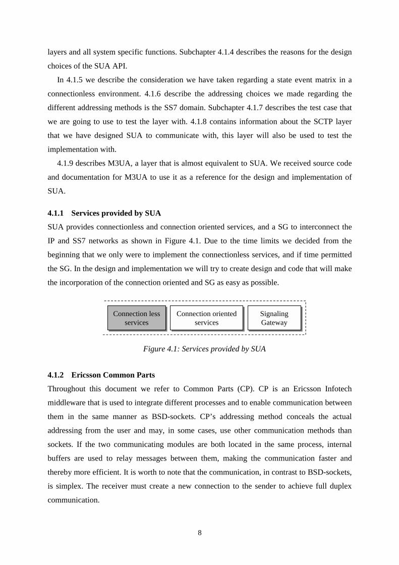
SUA provides connectionless and connection oriented services, and a SG to interconnect the
IP and SS7 networks as shown in Figure 4.1. Due to the time limits we decided from the
beginning that we only were to implement the connectionless services, and if time permitted
the SG. In the design and implementation we will try to create design and code that will make
the incorporation of the connection oriented and SG as easy as possible.
Connection lessservices
Connection orientedservices
SignalingGateway
Figure 4.1: Services provided by SUA
4.1.2 Ericsson Common Parts
Throughout this document we refer to Common Parts (CP). CP is an Ericsson Infotech
middleware that is used to integrate different processes and to enable communication between
them in the same manner as BSD-sockets. CP’s addressing method conceals the actual
addressing from the user and may, in some cases, use other communication methods than
sockets. If the two communicating modules are both located in the same process, internal
buffers are used to relay messages between them, making the communication faster and
thereby more efficient. It is worth to note that the communication, in contrast to BSD-sockets,
is simplex. The receiver must create a new connection to the sender to achieve full duplex
communication.

9
The data sent through CP is treated as an octet stream where message boundaries are
maintained. CP also enables the layers to be located on different machines, thus enabling a
distributed system.
Figure 4.2 shows how the communication between two layers using CP works. The reason
CP is drawn on one side of the layers is because of problems with timing when using many
layers. Because of these timing problems the complete stack is often in one process and uses
the same instance of CP.
Com
mon Parts
Layer A
Layer B
Figure 4.2: Communication trough Common Parts
Additionally CP also includes methods for memory management, linked lists and operating
system dependent functions for file management, timers and interrupt services.
4.1.3 Naming conventions for inter-layer communication
There are some naming conventions that apply to communication between layers, these are
shown in Figure 4.3. When a layer wishes to use a service in the layer below, it sends a
request and, if the request requires an answer, the receiving layer answers with a
confirmation. In the case that a layer wants to inform the layer above about some event, for
example data arrival, an indication is sent.
In the SUA layer, we receive indications from the SCTP layer and requests from the SCCP
user, in the same way we send indications to the SCCP user and sends requests to the SCTP
layer. The SCCP primitives that we handle are listed in Appendix D.
Note that the answer to an indication is called response, but neither SCTP nor SCCP use
this and it has therefore been omitted.

10
SCCP User
Request
Indication
Confirm
ation
SUA
Request
Indication
Confirm
ationSCTP
Figure 4.3: Inter-layer communication naming conventions
4.1.4 API considerations
In the case of SUA, we emulate a SCCP layer. We are therefore forced to use the interface
that Ericsson has defined for their implementation of SCCP. Due to this fact, there will not be
any need to write an API for SUA. Instead we will "intercept" the requests sent through CP
from the upper layers that is intended for the SCCP layer and send the responses in the same
manner to the layers above. This approach is shown in Figure 4.4, where section 1 and section
2 in the figure should be able to change places without the layers above noticing anything.
This has the benefits that layers above SUA/SCCP will not need to be reconfigured or
recompiled.
In the communication with SCTP, we will not use the SCTP API, since this is the standard
approach within Ericsson Infotech. Instead, we will communicate directly with SCTP through
CP as we did in the upper layer cases.

11
SUA User
SUA
SCTP
SCCP User
SCCP
Section 1
Section 2
Com
mon Parts
Com
mon Parts
Figure 4.4: SUA/SCTP SCCP exchangeability
4.1.5 State event matrix implementation
Because we do not implement the connection-oriented classes, we only have one state. There
is therfore no need for a state-event matrix. Nevertheless, we chose to use one in the
implementation to make it easier to add more classes later.
4.1.6 The addressing issue
The SCCP standard supports many addressing modes, partly because of all the different
addressing modes adapted by the standardization organizations that cooperated in developing
SCCP. For this project, we have decided to only support the addressing modes that the test
application requires to function properly.
4.1.7 Test cases
The environment that the SUA prototype is going to be tested in is the one described in Figure
3.2. The exception is that the SUA layer on the right side of the SG will be an endpoint during
the first stages of the test. If we have enough time to implement the SG, we will expand the
test environment to fully comply with the one described in Figure 3.2.
4.1.8 SCTP “snapshot1”
The layer directly under SUA, SCTP, is currently being implemented by Ericsson Infotech
and we work with an internal build from 2001-05-10 that is reported to implement the
1 An internal build at a specified time

12
services we require. However we received it a little late in the project so we may not be able
to use it.
4.1.9 Supplied foundation
Ericsson Infotech AB provided an implementation of a similar layer, M3UA. This is being
implemented by the company and we were supposed to use it as a reference for our
implementation. But due to delays within development the source code of the layer was not
debugged, and developed far enough, so we were unable to use it as a reference.
4.2 SUA
This subchapter describes the design choices we made for the SUA layer.
4.2.1 contains the parts of the SUA draft that we chose to implement and the parts that we
omitted. In 4.2.2 we describe the design issues that apply to our implementation of the SUA
draft. 4.2.3 describes how we divided the SUA layer into different modules, note that in this
case a module is equivalent with an object file.
4.2.1 Subset definition
This section describes those parts of SUA that we decided to implement and those parts we
decided to not implement.
4.2.1.1 SCCP Message classesIn this project, we have decided to only implement message classes 0 and 1. These classes are
the ones that provide the connectionless services. This choice is made because we feel that the
time needed to implement the connection-oriented services is greater than the time available
for this project.
Class Connectionless Ordered Bi-directional Flow control0 Yes No No No1 Yes Yes No No2 No Yes Yes No3 No Yes Yes Yes
Table 4.1: SCCP/SUA message classes
The difference between the two message classes is, as Table 4.1 shows, that the messages
in class 0 are unordered while they are ordered in class 1. This difference causes no
difficulties since SCTP provides a method to emulate both these services, within its

13
connection-oriented services. We can also rely on it for the transport of the messages in a
ordered or a not necessarily ordered fashion.
4.2.1.2 Security
Due to the fact that we are developing a prototype the parts of the draft that have to do with
security have been omitted. Thus we don’t guarantee
• Availability of reliable and timely user data transport.
• Integrity of user data transport.
• Confidentiality of user data.
4.2.1.3 Supported architecturesAs previously stated we will only support one architecture, the SS7-IP case as described in
Figure 3.2. The differences between SS7-IP and IP-IP domains are small, but we have
received information about other projects by Ericsson Infotech that implemented a similar
protocol, M3UA, had some problems with the IP-IP architecture. We have therefore decided
not to support IP-IP architecture and concentrate on the SS7-IP architecture.
4.2.2 General design issues
4.2.2.1 State event graph
Due to the fact that we only use the connectionless services, the state event graph is fairly
simple. The only state we have is Idle, which waits for events. On all events the layer takes
the appropriate action and then returns to Idle waiting for new events as described in Figure
4.5.
SCTP is on the other hand connection oriented, but because SUA connects to all other
known SUA nodes at startup we only need to keep track of the availability of the other nodes
and respond to connection requests from new SUA nodes when they are initializing.
Idle
Request/indication
Figure 4.5: SUA state event graph

14
4.2.3 Modular design
During the design of the SUA layer, we distinguished three different parts that SUA is
composed of, or actually four, if you count the SG as a part.
Each of the parts is in essence the interface to either another layer in the local protocol
stack or, as the SUA module, the interface to another SUA layer in another protocol stack.
Due to this we decided to divide the code into three independent modules, not including the
main module. Each module manages the messages from the different layers through
dispatchers and function matrixes. The first module is the most important module of the
project, the SUA module, the two remaining modules are the ones that manage
communication within the protocol stack, namely the SCTP module and the SCCP module.
The modules, and how they conceptually communicate within the layer, are described by
the dashed lines in Figure 4.6. Each module, except main, is conceptually the interface to
another layer, even if main actually receives all the messages to the layer and calls the
appropriate dispatcher.
SUA
SCCP
SCTP
Main
SCCP/SUA User Layer
SCTP Layer
SCCP/SUA UserLayer
SCTP Layer
SUA Layer
SUAModules
Figure 4.6: Modular design of SUA
The need to have a SCTP module is easy to grasp since the layer under SUA is SCTP.
Since SUA tries to emulate SCCP it needs to be transparent to the layers above, this dictates
that SUA must use the same interface as SCCP. Without the SCCP interface the layers above,
that previously used SCCP, would need to be recompiled to be able to use SUA.

15
4.3 SG
Due to lack of time and problems with the environment, especially SCTP, we chose not to
design the SG. However we took the SG under consideration during the design of the SUA
layer, and we do not perceive any complications that can arise from the decision to not
incorporate the SG.
5 Implementation and test
This chapter describes how we implemented the design. It also describes the results of the
testing of the implemented code.
Section 5.1 describes the methods we used when we implemented the functions needed in
the prototype. The next section, Section 5.2, explains how we combined the functions and
created and tested the modules the prototype consists of. Finally the last Section 5.3 describes
how we implemented and tested the complete prototype.
5.1 Functions
Originally we planned to use a standardized function header that is used by Ericsson, however
we were never informed on what the different input parameters was for and we were therefor
forced to create our own function header.
During the implementation of the functions we used the top-down method, partially
because this would make it easier to spot errors in the SUA draft early on. Additionally we
did not have the environment, mainly SCTP and at the beginning CP, to use any other
method.
Testing the functions that decode were done by creating the messages, byte by byte, that
the functions were to decode and then evaluate the outputted results. With the functions that
encode messages we used a similar approach, but instead of creating a message we evaluated
the encoded messages that were outputted from the functions, as shown in Figure 5.1.
Data Function Byte-stream
Figure 5.1: Function testing approach

16
5.2 Modules
5.2.1 Common implementation solutions
All the modules we created, except the SUA_main module, incorporate three key concepts;
event, state event matrix and dispatcher. The SUA_main module calls the dispatcher, in the
specified module, after it has received the data from another layer. An exception to this is the
SUA dispatcher that is called when the SCTP module has decoded the message received from
the SCTP layer.
The dispatcher identifies an event based on the data sent to the module. After this the
function pointed to in the state event matrix that is matched by the event, as shown in Figure
5.2, is executed. Because we, as previously stated, only have one state the matrix is actually a
one-dimensional array.
Event
Event function 1 pointer
Event function 2 pointer
Event function 3 pointer
Event function n pointer
Function matrix
Figure 5.2: Using a state event matrix (array)
5.2.2 SUA_main
This module includes the main function that is called when the module is started. It also
initializes the layer, and contains the loop that receives all messages from the other layers in
the stack.
Depending on where the message originated the message is directed to the dispatcher of
the module that is created to handle that message type. The messages can either come from an
SCCP user or SCTP. This is shown in Figure 5.3.

17
SCCP User layer
SCTP layerSCTP
[SCTP dispatcher]
SCCP[SCCP dispatcher]
SUA_main
SUA layer
Figure 5.3: Communication between SUA_main and the SCTP and SCCP modules
5.2.3 SUA
Due to the fact that one of the main goals of our project was to prototype the SUA draft, we
started with the implementation of the connectionless parts of the SUA protocol.
This was done with the hope that if we found any inconsistencies, that we missed during
the design phase, or parts of the draft that were problematic to implement we would find them
as soon as possible.
The possible problems we had foreseen in version 04 of the draft had disappeared in
version 05, which we changed to during the beginning of the design phase.
SUA messages are composed of one common part that includes version, message size and
what type of message it is and one variable part as Figure 5.4 shows. The part of the SUA
messages that changes between the different message types is composed of small units of
information, called parameters, with a format that all message types use.
Common part
Parameter 1
Parameter 2
Parameter n
Figure 5.4: SUA message format
These parameters made it possible for us to implement and test each of the units before we
merged them. The completed messages were thereafter created one by one and tested. When

18
we had enough SUA messages for the connectionless communication, we tested them
together simulating a communication between two SUA layers, as shown in Figure 5.5.
Send message
SUA Module
Encode message
Dispatch message
Decode message
Figure 5.5: SUA: message path in module test case
The communication we simulated was the sending of a heartbeat, this message requires an
answer, a heartbeat ack as shown in Figure 5.6. Instead of sending it over SCTP we sent it to
the dispatcher, as if we received it from the other side. Then we did the same thing with the
heartbeat ack. For verification of the result we printed a text to the screen informing us about
which message we received.
SUASUA
Heartbeat
Heartbeat Ack
Figure 5.6: SUA: sequence of heartbeat message
5.2.4 SCTP
When we implemented the module we based it on a design that is able to communicate with
more than one SCTP host in another stack even if this prototype only allows one foreign
SCTP host.
In the SUA module, we created functions for encoding and decoding of parts of a message
and combined them to encode/decode complete messages. As a contrast to this, in the SCTP
module we implemented the encoding and decoding of the messages as complete functions
from the beginning. The approach we used in the SUA module was not possible to use since
the SCTP primitives do not use the modular approach that SUA messages have.
But just as in SUA we tried to emulate a connection and send messages and checked if the
responses were correct. In the case of SCTP it was more complicated to test the module,
because without the SCTP layer any error made in the encoding/decoding of the messages

19
would not be noticeable during a module test. As a consequence of this we only checked the
encoding/decoding of data packets through a gateway function, as shown in Figure 5.7.
Send message
Gateway
SCTP_DATA_ARRIVE_INDICATIONSCTP_SEND_REQUEST
SCTP Module
Encode message
Dispatch message
Decode message
Figure 5.7: SCTP: module test case message path, using a gateway function.
5.2.5 SCCP
The SCCP standard is older than both the SUA and SCTP standards, and the documentation
of it is therefore more complete. It is also an ITU standard and therefore vastly more
complicated than the often ad hoc standards made by IETF.
As in the case with SCTP the messages were created and tested as a whole, but we did not
make any module test. The messages we needed for the connectionless communication did
not include anything that would be usable in a module test case.
5.3 Prototype
The testing of the prototype became somewhat more complicated than we had anticipated.
This was mainly due to the delay in the delivery of the test environment. This delay meant
that we did not have any test application, and therefor we choose not to incorporate any of the
SCCP addressing methods in this prototype.
Basically, when we tested the prototype we combined the test cases from the SUA module
and the SCTP module. The SUA module sends a heartbeat from one SUA layer to another. In
this case it sends to itself, but this does not affect the test, through the SCTP interface.
In the test we used the same gateway function from the SCTP module test, letting the SUA
message travel within the process, crossing the boundaries between the SUA and SCTP

20
module. Figure 5.8 shows how the encoders, decoders and dispatchers of the two modules
worked together.
Send message
Gateway
SCTP_DATA_ARRIVE_IND
SCTP_SEND_REQ
SCTP Module
Encode message
Dispatch message
Decode message
Send message
SUA Module
Encode message
Dispatch message
Decode message
Figure 5.8: Prototype: test case message path
6 General problems
This chapter describes the problems we encountered during the project.
6.1 Problems encountered with the SUA-draft
One of the main objectives of this project work was to find problems with the defined draft so
that the next version could be changed to solve or supply possible solutions to the problems.
This chapter describes the problems we encountered.
When this project started the current version of the SUA-draft was 04, when we were
reading it we found some unclear parts. The correct interpretation of most of the small errors
could easily be deduced from the surrounding text. Nevertheless some of the unclear parts
were more serious and impossible for us to completely interpret. In a few of the parameter
definitions the schematics of the parameters were in conflict with the written description of

21
the data fields. This meant that we would not be able to create SUA messages that were
guaranteed to work with other implementations of the draft.
Before we were able to report those errors a new version of the draft was issued, and in the
new draft the errors we had found in the previous version had been solved.
6.2 Administrative problems
The requirement from Ericsson was that we were to work in a workspace supplied by
Ericsson. This created a problem since the section of the building where we worked did not
have enough workstations from the beginning. Some days we were forced to share one
computer when two computers would have been more optimal.
Mostly during the later part of the project our supervisors at Ericsson Infotech had some
unforeseen changes in their schedules. This caused some small problems resulting in sparse
contacts between us during a limited period and some delays from both parties, basically the
source code of M3UA were delivered later than initially planed and delayed our design phase.
During the test phase we initially intended to use a test tool that Ericsson Infotech uses
when they develop layers, but neither of our supervisors had the possibility to configure this
tool within a reasonable amount of time.
6.3 Technical problems
The Ericsson computer network had, sometimes, technical problems and we were not able to
write anything on the report. Trying to work around the problem cost us a few hours of work.
During the first weeks of documentation Microsoft Word 97 SR-2 [en] and/or the
document template provided by the faculty, caused problems with the line spacing, sometimes
the line spacing varied within the same paragraph. Later on this problem simply disappeared.
Instead we have had, from time to time, several different types of problems where Word
distorted the document upon saving it. To restore the document we used Sun StarOffice 5.2,
but this would only restore the text forcing us to once more create the figures and the structure
of the documentation.
Additionally we were unable to use cross-references as we worked on the documentation
since Word would at times insert the referenced object instead of the reference caption.

22
6.4 SCTP problems
The SCTP layer is, as we have already mentioned in 4.1.8, under development by Ericsson
Infotech. Some technical, and administrative, problems arose when the SCTP was to be
delivered to us. This, and the previously mentioned schedule changes for the supervisors at
Ericsson Infotech, delayed SCTP to the length that we were unable to test SUA with SCTP.
Earlier on when we started to implement the function to communicate with SCTP we
discovered that the SCTP documentation we received was unclear, especially the parts that
described the format of the data that is sent between the layers in stack. One field was
described in three different ways, all incompatible with each other. We got in contact with
one of the employees of Ericsson Infotech that was involved in the development of the SCTP
layer and asked him what the documentation meant. After he studied it he could not deduce
what it meant and got in contact with the team that creates the SCTP module, and he gave us
the, hopefully, correct information.
7 Results
This chapter contains the results we achieved during the studying and prototyping the SUA-
draft.
We did not have time to do the complete test, which we had hoped we would be able to do
from the beginning, to send a message between the IP domain and SS7 domain. Neither did
we have time to use SCTP to send a message between two SUA nodes within an IP-network,
even if we had written all the source code we needed. We felt that the tweaking to get the
SCTP layer, that we received a little late in the project, and the SUA layer to work together
would require to much time. We decided to go on with what we had and finish off the project
in time.
During the tests we made we received the expected results. The fact that we only
implemented and tested the connectionless part, and therefore omitted the more complicated
connection-oriented part, may partly explain that we did not encounter any serious problems.
We were, as previously mentioned, unable to test SUA together with SCTP. Despite this
we still feel satisfied that, from the achieved results, we are able to draw some conclusions,
with quite high reliability, about the connectionless part of SUA.
Further on we have gathered experience when working on the project, partly about an
implementation of an IETF standard (draft) and also the benefits of using coding rules.

23
8 Conclusions
This chapter contains the conclusions we drew while we were studying and prototyping of the
SUA-draft.
Despite the fact that this has nothing to do with SUA, we will start with the conclusions
about one of the things that have annoyed us most of all. The conclusions we have drawn
about the use of MS Word to create documentation is that at least MS Word 97 SR-2 [en] is
not very stable and produces very bloated documents. One can question if the Computer
Science faculty should provide a template when Word obviously is not suitable for documents
of the size and type required for the bachelor’s project documentation.
Moving on with the conclusions about the SUA layer, we feel quite certain that at least the
connectionless, and probably the connection-oriented, parts of the draft are correct. We did
not find any inconsistencies in version 05 of the draft, and neither did we encounter any
problems during the design or implementation of the prototype. Despite that we only worked
with the connectionless parts we find that there is nothing that indicates that the connection-
oriented parts should be incorrect. Further on the quality of the draft indicates, or so we
believe, that that the draft is soon to be finalized and become a proposed IETF standard.
Despite that SUA is made to allow SCCP applications and application layers to work over
IP, much of the information that SUA and the application/application layers exchange is
really not needed if both SUA nodes exists within the IP domain. There may be a future need
of a SUA interface that is more adapted to the IP environment, without the SS7 overhead,
even if the old SCCP interface should be kept for legacy reasons.
By following guidelines for creating source code the resulting source code becomes much
easier to comprehend and less error-prone.

24
References
[1] J. Loughney et. al., SS7 SCCP-User Adaptation Layer (SUA) draft 05, (February 1,2001)Available from http://www.ietf.org/internet-drafts/draft-ietf-sigtran-sua-05.txt (February1, 2001)
[2] R. Stewart et. al., RFC 2960 Stream Control Transmission Protocol, (October, 2000)Available from http://www.ietf.org/rfc/rfc2960.txt (October, 2000)
[3] ITU-T Q.711 Functional description of the Signalling Connection Control Part ITU-T Q.712 Definition and function of signalling connection control part messages ITU-T Q.713 Signalling Connection Part formats and codes ITU-T Q.714 Signalling Connection Part procedures ITU-T Q.715 Signalling Connection Part user guide ITU-T Q.716 Signalling Connection Part (SCCP) performance

25
A Acronyms and abbreviations
ANSI American National Standards Institute
AP Application Protocol
API Application Program Interface
ASP Application Server Process
BSD Berkeley Software Distribution
Build A complete recompilation of all source files
CP Common Parts (Ericsson Infotech product)
ETSI European Telecommunications Standards Institute
IETF Internet Engineering Task Force
IP Internet Protocol
ITU International Telecommunication Union
ITU-T ITU Telecommunication Standardization Sector
IWF Inter Working Function
MTP2 Message Transfer Part - level 2
MTP3 Message Transfer Part - level 3
PSTN Public Switched Telephony Network
RANAP Radio Access Network Application Part
SCCP Signaling Connection and Control Part
SCTP Stream Control Transmission Protocol
SEP Signaling End Point
SG Signaling Gateway
Snapshot An internal build at a specified time
SS7 Signaling System number 7
STP SS7 Signaling Transfer Point
SUA SCCP User Adaptation layer
TCAP Transaction Capability Application Protocol
TCP Transmission Control Protocol
WIP Work In Progress

26
B Development environment
This includes a description of the environment and programs that we used when we developed
and compiled the prototype.
• SUN workstation running Solaris 2.7
• ANSI C compiler gcc 2.8.1
• GNU make 3.79.1
• Ericsson Infotech Common Parts R8
• Ericsson Infotech SCCP API R1
• Ericsson SCTP

27
C SUA Message Classes and Types
These are the different message types that are defined in the SUA draft. But we only support
the connection-less messages.
Message Type
Error
Notify
Table C.1 SUA Management Messages
Message type
Destination Unavailable
Destination Available
Destination State Audit
SS7 Network Congestion
Destination User Part Unavailable
SCCP Management
Table C.2 SS7 Signaling Network Management
Message Type
ASP Up
ASP Down
Heartbeat
ASP Up Ack
ASP Down Ack
Heartbeat Ack
Table C.3 Application Server Process Maintenance
Message Type
ASP Active
ASP Inactive

28
ASP Active Ack
ASP Inactive Ack
Table C.4 ASP Traffic Maintenance Messages
Message Type
Connectionless Data Transfer
Connectionless Data Response
Table C.5 Connectionless Messages
Message Type
Connection Request
Connection Ack
Connection Refused
Release Request
Release Complete
Reset Confirm
Reset Request
Connection Oriented Data Transfer
Connection Oriented Data Ack
Connection Oriented Error
Inactivity Test
Table C.6 Connection-Oriented Messages

29
D Supported SCCP PDU Primitives
These are the primitives the SUA layer supports.
Primitive Name
N Bind Request
N Bind Confirm
N Unbind Request
N Unidata Request
N Unidata Indication
Table D.7: SCCP Primitives