Embed Size (px)
Citation preview
International Journal of Scientific & Engineering Research, Volume 4, Issue 11, November-2013 2019 ISSN 2229-5518
IJSER © 2013 http://www.ijser.org
Chemical Stabilization of Laterite Soils for Road
construction CASE STUDY: THE LATERITE SOILS AT LEGON
Dr. Francis Achampong1*, Reginald Adjetey Anum2, Prof. Fred Boadu3, Nene
Boso Djangmah4, Dr. L.P. Chegbele5
1*. Corresponding author, Civil/ Geological/ Geotechnical/Environmental
Engineer,[email protected]
2. Assistant Researcher, Earth Science Department, University of Ghana.
3. Associate professor, Duke University, United State of America.
4. Teaching assistant, Earth Science Department, University of Ghana.
5. Lecturer, Earth Science Department, University Ghana.
ABSTRACT
Most roads in Accra (Ghana) don’t stand the test of time and don’t live out their
designed life span due to inferior soils used as sub-base in their construction. Presently,
engineers and contractors deal with such soils by removing them and replacing them
with superior materials such as imported gravels to help improve the strength of the
soils. The importation of these desirable materials for construction is very costly. More
efficient method which uses less energy and is less expensive in dealing with poor soils
for road construction is chemical stabilization. The objective of this project therefore is
to chemically stabilize poor sub-base soil to be used for road construction using lime and
cement as additives.
The soil sample was laterite collected from an exposed trench during a construction
project near the University of Ghana. This sample was subjected to various tests
including grading, Atterberg limits, swelling as well as compaction and California
Bearing Ratio (CBR) tests. Results from the tests showed that: the soil was well graded,
with all the soil fractions being retained on each of the sieves used, the soil contained a
minimal amount of clay evidenced by the increased of 1ml in the swelling test, and the
compaction test for the raw sample yielding Maximum Dry Density (MDD) of
1869kg/m3 and Optimum Moisture Content (OMC) of 13.9%.For the lime stabilized
sample, PI was 11, 7 and 0; LL was 34, 30 and 0 and CBR of 28%, 31% and 126% all
for 2%, 4% and 6% lime addition to the raw sample respectively. For the cement
stabilized sample, PI was 15, 14 and 11; LL was 37. 34 and 31and CBR was 14%, 74%
and 236% all for 2%, 4% and 6% cement addition to the raw sample respectively. Hence
IJSER
International Journal of Scientific & Engineering Research, Volume 4, Issue 11, November-2013 2020 ISSN 2229-5518
IJSER © 2013 http://www.ijser.org
it was concluded that only 6% lime addition was the most suitable for stabilizing the soil
when the results were compared to the specifications of the Ghana Highway Authority
(GHA). It is recommended that the economic implications of the use of lime for
chemical stabilization in Accra, Ghana should b encouraged.
KEYWORDS: Sub-grade; Stabilization; Lime; Cement; Laterites; Grading;
Atterberg limits; Swelling; Compaction; California Bearing Ratio (CBR);Ghana
Highway Authority (GHA).
1. INTRODUCTION
1.1 Statement of the problem.
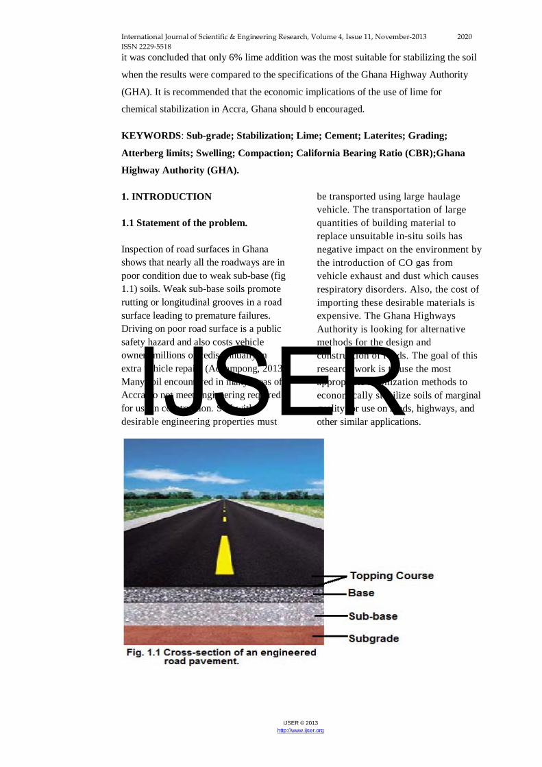
Inspection of road surfaces in Ghana shows that nearly all the roadways are in poor condition due to weak sub-base (fig 1.1) soils. Weak sub-base soils promote rutting or longitudinal grooves in a road surface leading to premature failures. Driving on poor road surface is a public safety hazard and also costs vehicle owners millions of cedis annually in extra vehicle repairs (Achampong, 2013). Many soil encountered in many areas of Accra do not meet engineering required for use in construction. Soil with desirable engineering properties must
be transported using large haulage vehicle. The transportation of large quantities of building material to replace unsuitable in-situ soils has negative impact on the environment by the introduction of CO gas from vehicle exhaust and dust which causes respiratory disorders. Also, the cost of importing these desirable materials is expensive. The Ghana Highways Authority is looking for alternative methods for the design and construction of roads. The goal of this research work is to use the most appropriate stabilization methods to economically stabilize soils of marginal quality for use on roads, highways, and other similar applications.
IJSER
International Journal of Scientific & Engineering Research, Volume 4, Issue 11, November-2013 2021 ISSN 2229-5518
IJSER © 2013 http://www.ijser.org
1.2 Background of the study
The long-term performance of any construction project depends on the engineering competence of the underlying soils. In the construction and maintenance of transportation facilities, geomaterials (soils and rocks) must be stabilized through chemical and mechanical processes. The main purpose of stabilization is to improve the soil strength, bearing capacity, durability under adverse moisture and withstand both static and dynamic stress. Stabilization of the geomaterials can aid in dust control on roads and highways, particularly unpaved roads, in water erosion control, and in fixation and leaching control of waste and recycled materials.
1.2.1 Chemical stabilization
Chemical stabilization includes the use of admixtures (chemicals and emulsions) as cementing agents, modifiers, water proofing, water retaining and miscellaneous chemicals to improve the engineering properties of undesirable soils. The behavior of each of these admixtures differs vastly from the others; each has its particular use and conversely each has its own limitations (Gidigasu, 1976). The main admixtures to be considered in this work are cement and lime. Cement and lime stabilization modifies the physiochemical properties of cohesive soils as well as improve the static and dynamic strength.
Cement stabilization mechanism is mainly controlled by hydrolysis and hydration. Factors which affect physical properties of soil-cement include:
• Soil type(particle size distribution, grain shape, mineralogy)
• Proportion of soil , cementitious material and water content
• Quantity of cement • Degree of mixing • Time of curing and • Density of the of the compacted
mixture (Road Research laboratory, 1952; yonder, 1957).
Cement stabilization usually result in decreased density, increased compressive strength, decreased plasticity, decreased volume change characteristics of expansive clays when compared to the natural soil (PCA, 1992).
Lime is generally restricted to the warm to moderate climates, since lime-stabilized soils are susceptible to breaking under freezing and thawing. Lime stabilization will generally bring about a decrease in the density a change in the plasticity of the soil and an increase in the soil strength. The action of lime in soil stabilization may be reduced to three basic reactions (Gillot, 1968):
• Alteration of water film through cation exchange.
• Flocculation-agglomeration • Lime reaction with clay crystal
edges producing accumulation of cementitious materials which aid in the formation of new chemicals.
1.2.2 Laterite
Laterite is a group of highly weathered soils formed by the concentration of hydrated oxides of iron and aluminum (Thagesen, 1996). Other definitions have been the ratio of silica (SiO2) and sesquioxides (Fe2O3 + Al2O3). In laterites the ratios are less than 1.33.
IJSER
International Journal of Scientific & Engineering Research, Volume 4, Issue 11, November-2013 2022 ISSN 2229-5518
IJSER © 2013 http://www.ijser.org
Those between 1.33 and 2.0 are indicative of laterite soils, and those greater than 2.0 are indicative of non-lateritic soils (Bell, 1993). Experience has shown that lime works well with medium, moderately fine, and fine-grained clay soils. Attempts have been made to stabilize laterite soils for engineering purposes (eg. Winterkon and Chandrasekaran, 1951; Remillon, 1955). Most laterite gravels and gravelly soils are easy to win and distribute during construction, and give high laboratory and field compaction densities (Evans, 1958; Daniel and Newill, 1959), however, their performance has been found to be poor under adverse traffic and moisture conditions (Nanda and Krisnamachari, 1958; Arulanandan and Tunbridge, 1969). There have been studies into the effect of chemical composition on the stabilization of laterite soils (eg., Winterkon and Chandrasekaran, 1951). The engineering properties of stabilized laterite soils depend on:
• Genetic characteristics • Compositional factors, such as
particle-sixe distribution, organic matter content, chemical and mineralogical composition, and physico-chemical characteristics etc. and
• Method of sample preparation prior to stabilization and the stabilization procedures
This research work sought to investigate the influence of lime and cement stabilization on the engineering properties of Laterite soils in Accra. Specific objectives covered are outlined below.
1.3 Objectives of the studies
The objectives of the studies are as follows:
• To establish the effectiveness of lime and cement stabilization on the sample collected.
• To compare the strength of the stabilized soils to the raw sample collected.
In order to effectively achieve the above objectives a rational work program was conducted. First, a comprehensive desk study was conducted in order to gather available relevant information, techniques, specification and parameter data on lime and cement. Procedures were followed to categorize the type of poor soil encountered. Tests were then performed to investigate the properties of the soil before and after stabilization; this was to potential for its applicability in Accra or make up for where data in the literature was not adequate.
1.4 Study area
The study area is Legon in Accra,Ghana. From Kesse ( ), they all form part of the Precambrian Togo series, which occur at the south eastern part of Ghana. The geology is dominantly metamorphosed and highly folded arenaceous and argillaceous group of rocks, in which the predominant rock types are quartzites and phyllites (Anum, 2013). Structures present are basically foliations and joints. The soil type is laterite.The coordinates include, 05039′25.3″ (N) and 000010′43″(w) with elevation 92m.
2. METHODOLOGY
The study covered representative sampling of the soils from the various locations, laboratory tests to stabilize the poor soils for engineering works (road
IJSER
International Journal of Scientific & Engineering Research, Volume 4, Issue 11, November-2013 2023 ISSN 2229-5518
IJSER © 2013 http://www.ijser.org
works) and the determination from the results gained of which of the soils sampled was the most favorable in terms of maximum strength gained after stabilization. Testing was done in accordance with specifications from the Ghana Highway Authority. Tests done included, but were not limited to, the following:
• Grading test • Atterberg limit test • Compaction Test • California bearing ratio
2.1 Sample collection and preparation
Samples were collected as per Ghana Highway Authority standards for soil stabilization tests. At the laboratory, the samples were mixed thoroughly in order to achieve a state where by any amount sample taken is representative of the entire sample and, by extension, the soil in the field. This was done by a process called refilling. Refilling is done by first dividing the sample into two equal parts using a set of equipment collectively known as the refilling box. Then one part is again divided into two equal parts. This process is continued until one is satisfied with the level of mixing.
2.2 Laboratory Test
2.2.1 Gradation analysis
This method is used primarily to determine the grading of materials proposed for use as aggregates or being used as aggregates. The results are used to determine compliance of the particle size distribution with applicable specification requirements and to provide necessary data for control of the production of various aggregate products and mixtures containing aggregates. Essentially, it is a practice or procedure used (commonly in civil engineering) to assess the particle size distribution of a granular material. The procedure according to Ghana Highway Authority standards requires that, after refilling,
two small quantities of the sample should be taken and put into two pans: one for washing of the sample and one for moisture content weight determination.
Apparatus: Two pans, 19.0mm, 9.5mm, 4.75mm, 2.0mm, 1.00mm, 0.425mm, 0.300mm, 0.150mm, 0.075mm sieves, washing bowl, balance/scale, vibrator.
Procedure: The masses of the two pans A and B were recorded. An appreciable amount of the sample was then taken and placed into pan A and weighed to obtain the weight of the moist sample plus the pan. It is then placed in an oven for 24 hours. This is for the moisture content determination. A smaller amount of the sample was placed into pan B and soaked in water for 24 hours. After 24 hours, the sample in pan A was removed from the oven and weighed to obtain the dry mass plus the pan. Then the sample in pan B was poured into a bowl and washed under a running tap by pouring the water through the 0.075mm sieve so that not all the soil is washed away (fig. 3.4). The useful ones were retained on the sieve whiles those that passed through the sieve were unwanted. Washing was done to take the dust or the unwanted particles out of the whole sample. This was done several times until the water used to wash the sample became clear (fig. 3.5). Then the sample was poured back into pan B, drained and put into the oven to dry. After 24 hours, pan B was removed from the oven and the washed dry sample was then weighed.
The gradation analysis of the dry washed samples was done using the sieves and the pan. The samples were then poured into the sieves arranged according to the largest sieve to the smallest sieve. The sieves containing the samples were placed under a vibrator (fig. 3.6). The vibrator shook the sieve for about 5 to 10 minutes to ensure that the samples passed through the sieves in order to obtain the various size fractions of the soil sample (fig. 3.7). The soil retained on each of the sieves were then poured
IJSER
International Journal of Scientific & Engineering Research, Volume 4, Issue 11, November-2013 2024 ISSN 2229-5518
IJSER © 2013 http://www.ijser.org
to a plate and weighed. Values were recorded on the data sheet.
The sieves were nested in order of decreasing size of opening from top to bottom and the sample was placed on the top sieve. The sieves were agitated by the vibrator until meeting the criteria for adequacy of sieving i.e. for about 10 minutes and then removed from the vibrator. The top sieve was removed and the retained material was brushed into a pan, which is then weighed and recorded. Each sieve cleaned thoroughly. This process was repeated with each succeeding sieve; brushing the material into individual pans, and recording the non-cumulative weights.
2.2.2 Atterberg limit test
Apparatus: 0.425mm sieve, pans, mortar, pestle, Cassagrande device, Grooving tool, Balance, Spatula, Distilled water, Wash bowl, Glass Plate, alluminium.
Procedure: 200g of the total sample was obtained by first breaking down the sample into smaller pieces (fig. 3.8) before passing it through the 0.425mm sieve (fig. 3.9). The raw sample was divided into two equal parts; one part for Liquid Limit test (LL) and the other for Plastic Limit test (PL). Two empty cans were weighed. The soil was moulded after adding water. Then 20g of the moulded sample was weighed and divided into two pans to be weighed again. The readings wererecorded. The raw sample was placed on the glass plate and distilled water was added in small amounts to adjust the water content of the mixture if it was too dry. The mixture was also allowed to dry at room temperature while mixing on a glass plate if it was too wet. This was done until a consistent mixture was achieved. A portion of the previously mixed sample was placed into the cup of the Liquid Limit of the point where the cup rests on the base. Air pockets were eliminated by squeezing the soil sample down and spreading it into the cup in the Cassagrande device to a depth of about
10mm at its deepest point. The sample formed an approximately horizontal surface. The grooving tool was then used to carve a space down the centre of the cup of the Cassagrande device (fig. 3.10). The cup was repeatedly dropped 10 mm onto a hard rubber base at a rate of 27-30 for the first blows. For example, when the first blows numbered less than 27, then there was less water in the sample and therefore distilled water was added. When the blows were greater than 27 then it was an indication that there was more water in the sample. When the required number of blows was achieved, the spatula was used to take some of the sample and placed it on the pan to be weighed and recorded. The sample was then placed in an oven for at least 16 hours. The remaining sample was remixed by adding small amount of distilled water to increase the water content. The previous steps were repeated for one additional trial to produce successively lower number of blows to close up the grove so that the number of blows will decrease: 23-27 for the second blows and 15-23 for the third blows.
2.2.3 Swelling test
Apparatus: two test tubes, 0.075mm Sieve, Mortar, Pestle, Pan, Distilled water, Salt, Kerosene.
Procedure: Using the mortar and pestle, the samples were broken down into smaller fractions. An appreciable amount of the sample was then sieved through 0.075mm. 10ml each of the samples was then poured into two different tests tubes. Salt solution was poured into one of the test tubes containing 10ml of the sample. In the other test tube, an appreciable amount of Kerosene was poured into the other test tube with the 10ml sample (fig 3.11). The test tubes are left for 24 hours for the swell to develop fully.
2.2.4 Compaction test
IJSER
International Journal of Scientific & Engineering Research, Volume 4, Issue 11, November-2013 2025 ISSN 2229-5518
IJSER © 2013 http://www.ijser.org
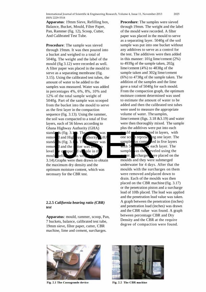
Apparatus: 19mm Sieve, Refilling box, Balance, Bucket, Mould, Filter Paper, Pan, Rammer (fig. 12), Scoop, Cutter, And Calibrated Test Tube.
Procedure: The sample was sieved through 19mm. It was then poured into a bucket and weighed to a total of 5040g. The weight and the label of the mould (fig 3.12) were recorded as well. A filter paper was placed in the mould to serve as a separating membrane (fig. 3.15). Using the calibrated test tubes, the amount of water to be added to the samples was measured. Water was added in percentages 4%, 6%, 8%, 10% and 12% of the total sample weight of 5040g. Part of the sample was scooped from the bucket into the mould to serve as the first layer in the compaction sequence (fig. 3.13). Using the rammer, the soil was compacted to a total of five layers, each of 56 blows according to Ghana Highway Authority (GHA) standards (fig. 3.16). The rammer was removed and Highway Authority (GHA) standards (fig. 3.16). The rammer was removed and the cutter was used to level the compacted sample in the mould before it was weighed (fig 3.14).Graphs were then drawn to obtain the maximum dry density and the optimum moisture content, which was necessary for the CBR test.
2.2.5 California bearing ratio (CBR) test
Apparatus: mould, rammer, scoop, Pan, 7 buckets, balance, calibrated test tube, 19mm sieve, filter paper, cutter, CBR machine, lime and cement, surcharges.
Procedure: The samples were sieved through 19mm. The weight and the label of the mould were recorded. A filter paper was placed in the mould to serve as a separating layer. 5040g of the soil sample was put into one bucket without any additives to serve as a control for the test. The additives were then added in this manner: 101g lime/cement (2%) to 4939g of the sample taken, 202g lime/cement (4%) to 4838g of the sample taken and 302g lime/cement (6%) to 4738g of the sample taken. The addition of the samples and the lime gave a total of 5040g for each mould. From the compaction graph, the optimum moisture content determined was used to estimate the amount of water to be added and then the calibrated test tubes were used to measure the appropriate volume of water. The samples, lime/cement (figs. 3.18 &3.19) and water were then thoroughly mixed. The sample plus the additives were put into each mould and compacted in layers, with one scoop representing one layer. The sample was compacted in five layers with 56 blows for each layer. The sample was then leveled using the cutter. Surcharges were placed on the moulds and they were submerged underwater for 4 days. After that the moulds with the surcharges on them were removed and placed down to drain. Each of the moulds was then placed on the CBR machine (fig. 3.17) or the penetration piston and a surcharge lead of 10Ib placed. The lead was applied and the penetration lead value was taken. A graph between the penetration (inches) and penetration load (inches) was drawn and the CBR value was found. A graph between percentage CBR and Dry Density and the CBR at the require degree of compaction were found.
IJSER
International Journal of Scientific & Engineering Research, Volume 4, Issue 11, November-2013 2026 ISSN 2229-5518
IJSER © 2013 http://www.ijser.org
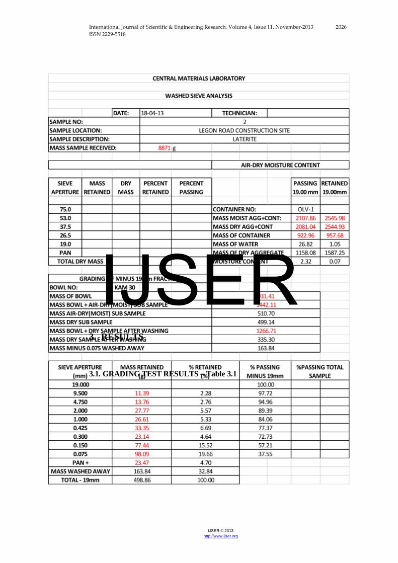
3. RESULTS
3.1. GRADING TEST RESULTS – Table 3.1
IJSER
International Journal of Scientific & Engineering Research, Volume 4, Issue 11, November-2013 2027 ISSN 2229-5518
IJSER © 2013 http://www.ijser.org
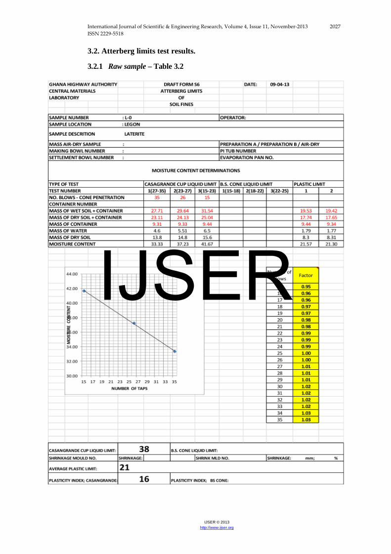
3.2. Atterberg limits test results.
3.2.1 Raw sample – Table 3.2
IJSER
International Journal of Scientific & Engineering Research, Volume 4, Issue 11, November-2013 2028 ISSN 2229-5518
IJSER © 2013 http://www.ijser.org
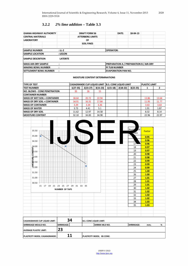
3.2.2 2% lime addition – Table 3.3
IJSER
International Journal of Scientific & Engineering Research, Volume 4, Issue 11, November-2013 2029 ISSN 2229-5518
IJSER © 2013 http://www.ijser.org
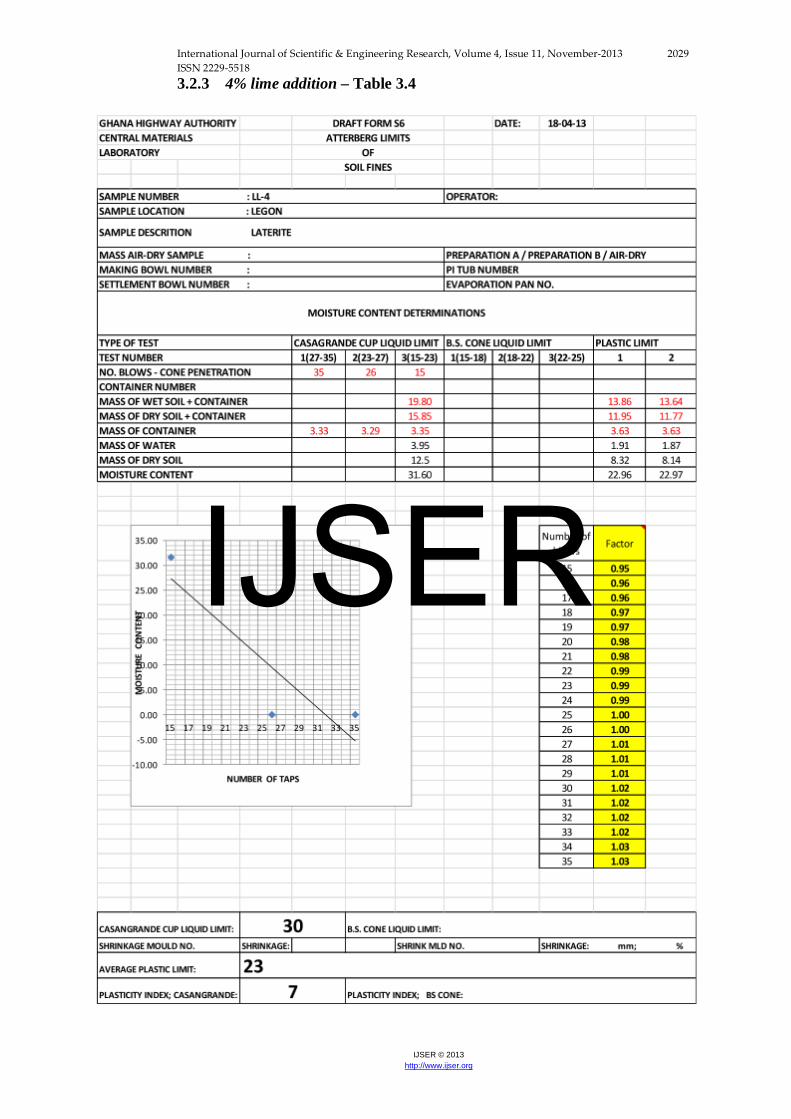
3.2.3 4% lime addition – Table 3.4
IJSER
International Journal of Scientific & Engineering Research, Volume 4, Issue 11, November-2013 2030 ISSN 2229-5518
IJSER © 2013 http://www.ijser.org
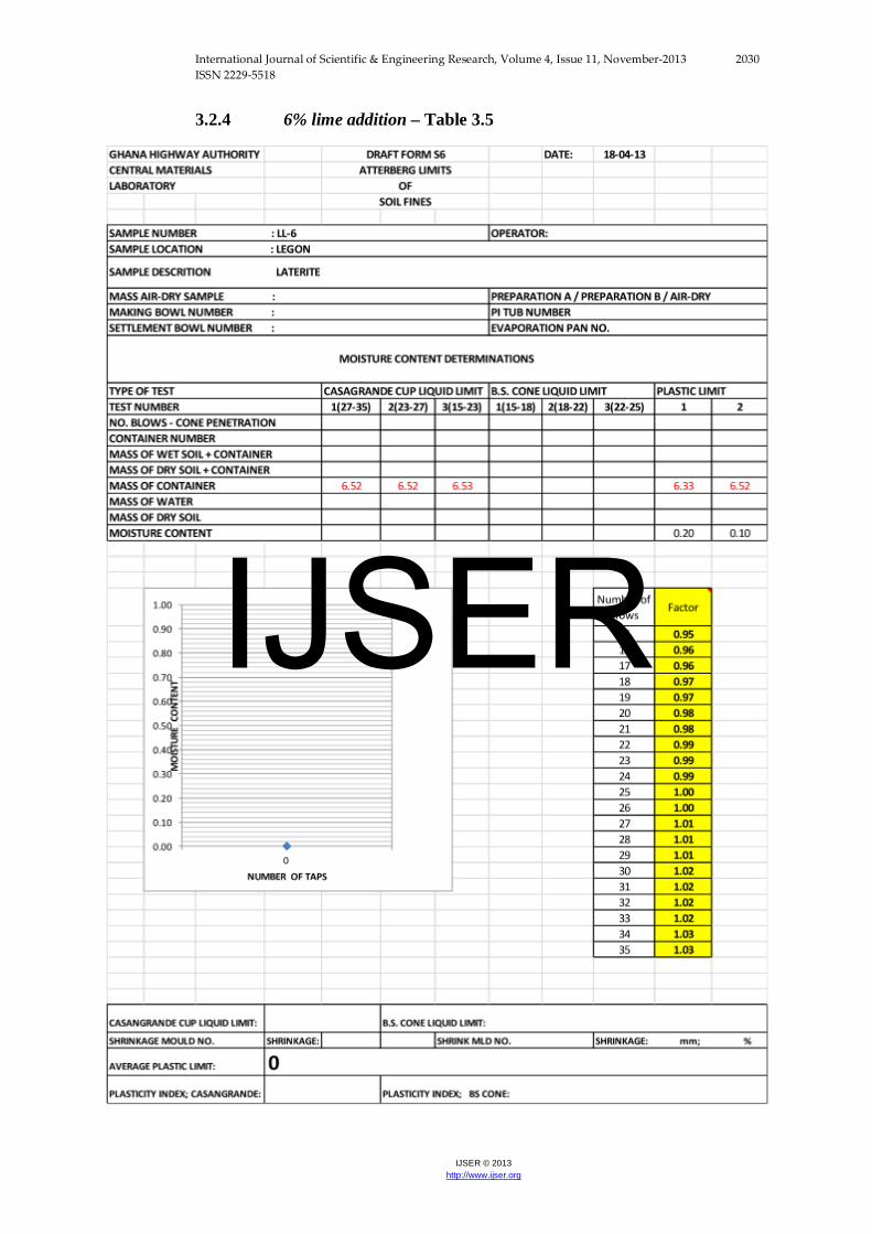
3.2.4 6% lime addition – Table 3.5
IJSER
International Journal of Scientific & Engineering Research, Volume 4, Issue 11, November-2013 2031 ISSN 2229-5518
IJSER © 2013 http://www.ijser.org
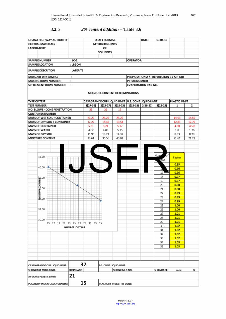
3.2.5 2% cement addition – Table 3.6
IJSER
International Journal of Scientific & Engineering Research, Volume 4, Issue 11, November-2013 2032 ISSN 2229-5518
IJSER © 2013 http://www.ijser.org
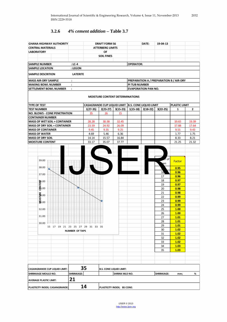
3.2.6 4% cement addition – Table 3.7
IJSER
International Journal of Scientific & Engineering Research, Volume 4, Issue 11, November-2013 2033 ISSN 2229-5518
IJSER © 2013 http://www.ijser.org
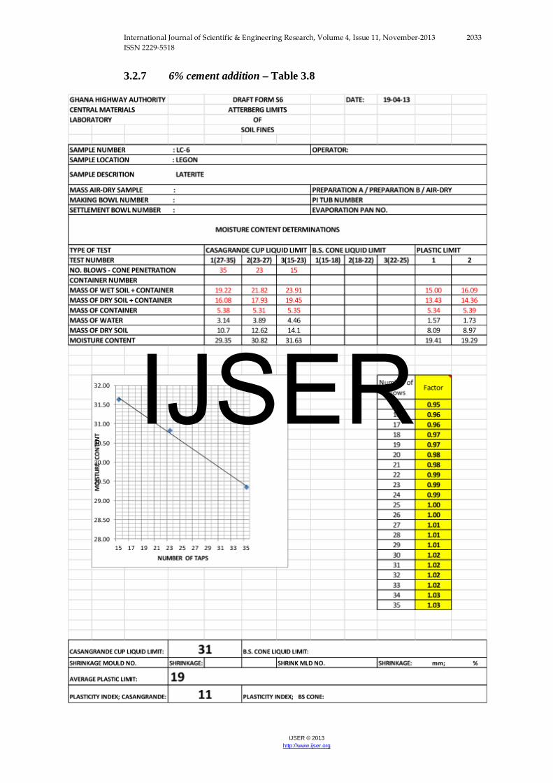
3.2.7 6% cement addition – Table 3.8
IJSER
International Journal of Scientific & Engineering Research, Volume 4, Issue 11, November-2013 2034 ISSN 2229-5518
IJSER © 2013 http://www.ijser.org
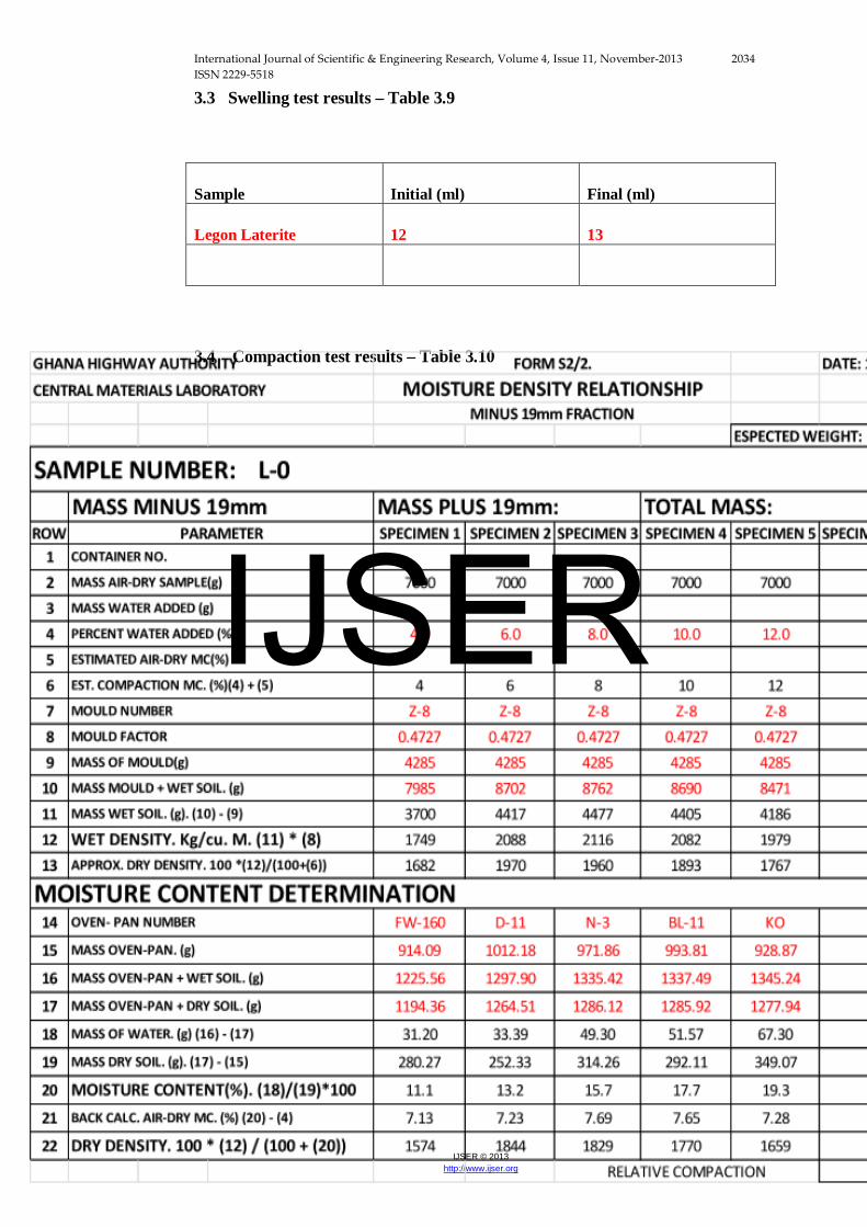
3.3 Swelling test results – Table 3.9
Sample Initial (ml) Final (ml)
Legon Laterite 12 13
3.4 Compaction test results – Table 3.10
IJSER
International Journal of Scientific & Engineering Research, Volume 4, Issue 11, November-2013 2035 ISSN 2229-5518
IJSER © 2013 http://www.ijser.org
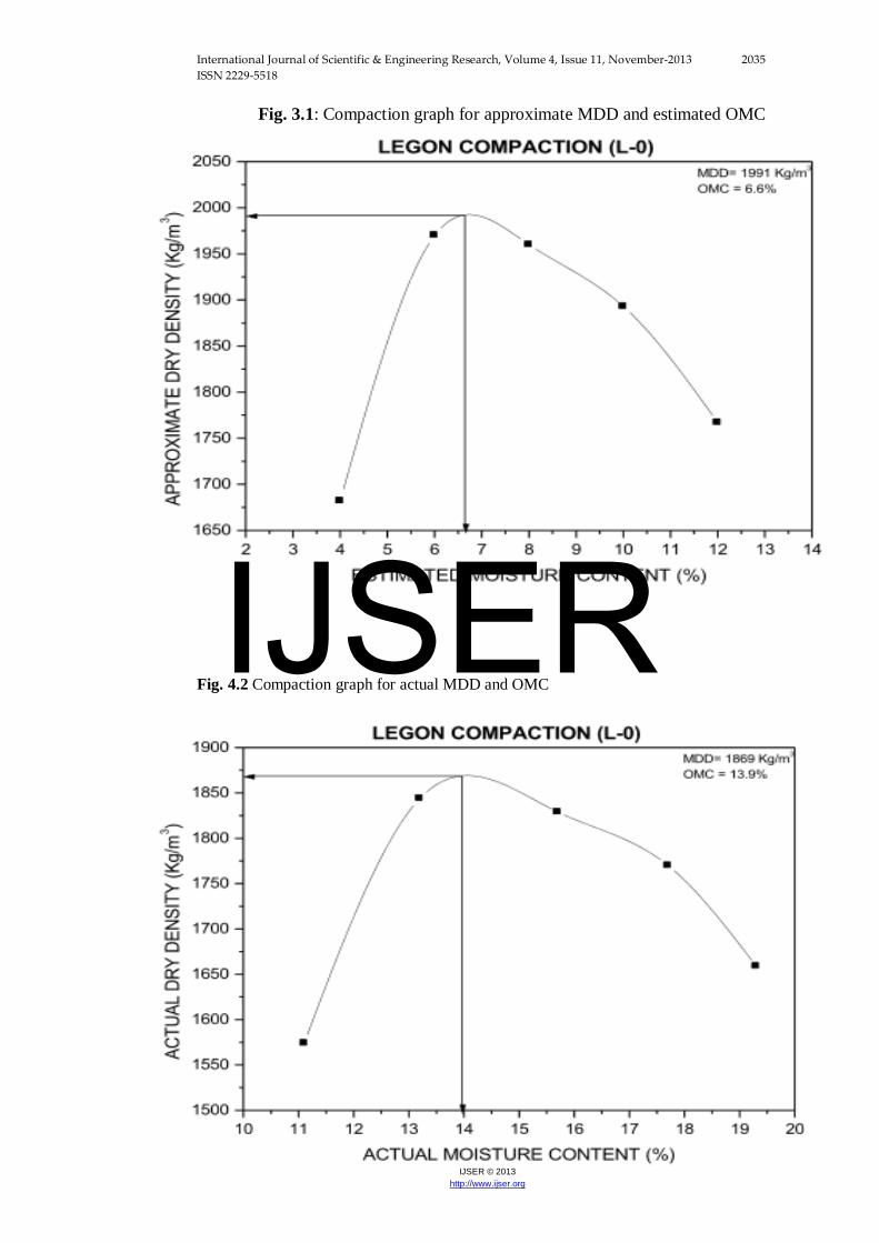
Fig. 3.1: Compaction graph for approximate MDD and estimated OMC
Fig. 4.2 Compaction graph for actual MDD and OMC IJSER
International Journal of Scientific & Engineering Research, Volume 4, Issue 11, November-2013 2036 ISSN 2229-5518
IJSER © 2013 http://www.ijser.org
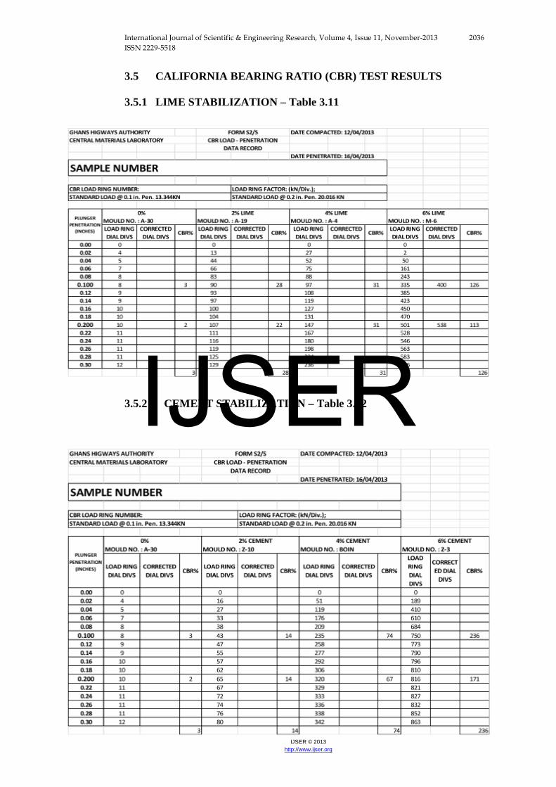
3.5 CALIFORNIA BEARING RATIO (CBR) TEST RESULTS
3.5.1 LIME STABILIZATION – Table 3.11
3.5.2 CEMENT STABILIZATION – Table 3.12
IJSER
International Journal of Scientific & Engineering Research, Volume 4, Issue 11, November-2013 2037 ISSN 2229-5518
IJSER © 2013 http://www.ijser.org
4. ANALYSIS AND DISCUSSION
4.1 Grading test
Results obtained from the test indicated that the sample was quite well graded with the percentage retained on each sieve ranging from 2.28% to 6.69%, with the exception of the 0.150mm and 0.075mm sieves retaining 15.52% and 19.66% respectively, although a large percentage of the sample (32.84%) was washed away.
4.2 Swelling test
The volume of the sample rose from 10ml to 12ml 24 hours after the kerosene was poured into one of the test tubes. This represented the actual height of the sample and acted as the control for the test. 24 hours after the water was added to the other test tube, the volume of the sample rose from 10ml to 13ml. this resulted in a 1ml difference in volume between the test tubes used for the test after 24 hours. Since the swelling test shows an indication of the clay content, the marginal increase in volume of the sample with water shows that there is a very small amount of clay in the laterite.
4.3 Standards of the Ghana highway authority
Road construction typically occurs in layers depending on the type of road i.e. either a flexible pavement or a rigid pavement. Most roads in Ghana are flexible pavements and as such this report concentrates on their characteristics. A flexible basically consist of the sub-grade, sub-base, base and topping courses. The sub-grade is the naturally occurring soil of the area upon which the road is built. It must be stable enough to support the road. The sub-base and the base are the “foundations” of the road and as such must be the strongest of the road layers/courses. If they are not, the road eventually suffers from warping as well as differential settlement or expansion.
It is for this reason that the GHA has specified minimum and maximum values for PI, LL and CBR of soil samples for both base and sub-base to be used for road construction. Non-compliance to these standards most certainly results in premature road failures.
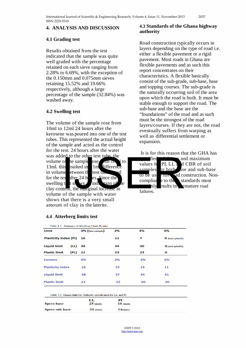
4.4 Atterberg limits test
IJSER
International Journal of Scientific & Engineering Research, Volume 4, Issue 11, November-2013 2038 ISSN 2229-5518
IJSER © 2013 http://www.ijser.org
Both the PI and the LL summary graphs show that lime stabilization was better at reducing the clay content of the sample than the cement stabilization, with the most reduction occurring at the 6% lime addition. Specifications from GHA require that the PI and LL obtained from Atterberg Limits tests fall within their standards. The PL parameter is not considered in this analysis. The summary tables show that the raw sample clearly does not meet the standards of the GHA for both PI and LL with respect to both the base and sub-base. For the lime stabilization, the PI test passed for 4% and 6% stabilization and the LL test passed for only 6% stabilization with respect to the base course, whiles the PI test passed for 2%, 4% and 6% stabilization and the LL test passed for 4% and 6% stabilization with respect to the sub-base course. For the cement stabilization, both the PI and LL tests did not pass the specification with respect to the base course, whiles the
PI test passed for 4% and 6% stabilization and the LL test did not pass the specification with respect to the sub-base course. 4.5 Compaction test The results of the compaction test
indicated that the sample achieved
an actual
maximum dry density (MDD) of
1869kg/m , but, more importantly,
attained actual
optimum moisture content (OMC) of
13.9%. This means that if the moisture
content of the soil increases beyond
this value during road construction the
soil is most likely
to fail due to oversaturation. The
OMC obtained was used in the CBR
test of the
sample.
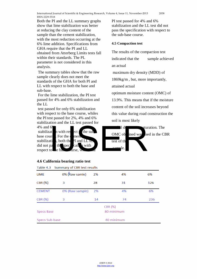
4.6 California bearing ratio test
IJSER
International Journal of Scientific & Engineering Research, Volume 4, Issue 11, November-2013 2039 ISSN 2229-5518
IJSER © 2013 http://www.ijser.org
Table 4.3 shows that there is a significant increase in the strength of the soil
Irrespective of the additive used. At 2% addition, the lime stabilization was
slightly
better than the cement stabilization, but the cement stabilization became better
than
the lime stabilization at 4% addition and then much better at 6% stabilization.
The summary tables show that the raw sample clearly does not meet the
standards of
the GHA for % CBR with respect to both the base and sub-base.
For the lime stabilization, the CBR test passed for only 6% stabilization with
respect
to both the base and sub-base courses. For the cement stabilization, the CBR test
passed for only 6% stabilization with respect to the base course whiles the same
test passed for both 4% and 6% stabilization with respect to the sub-base course.
5 CONCLUSION
From the analyses and discussions from the previous chapter, it can be inferred
that
6% addition of lime to the sample resulted in PI, LL and CBR values that passed
GHA specifications for both base and sub-base courses. It is therefore concluded
that both lime and cement stabilization improved the engineering properties of
the sample, but lime stabilization is the most suitable for Legon laterite soil for
road construction.
ACKNOWLEDGEMENT
Glory be to God almighty, the maker of all things. We extent our heartfelt
appreciation to multigeoconsult for contributing greatly to the success of this
research work through professional consulting as well being the sole funder. We
would like to extend our profound gratitude to the entire teaching staff of Earth
Science Department (University Of Ghana) for their persistent review and
thereby making immense contributions where necessary. In addition, a thank you
to the technicians of the Ghana Highway Authority (GHA) for availing their
resources in running this research.
We also give sincere thanks to Ama Achampong (University of North Carolina,
U.S.A) and Akua Achampong (Princeton University, New Jersey, United States.)
IJSER
International Journal of Scientific & Engineering Research, Volume 4, Issue 11, November-2013 2040 ISSN 2229-5518
IJSER © 2013 http://www.ijser.org
for their valuable and constructive suggestions during the planning and
development of this research work. To Mrs. Priscilla Anum (Bodo University,
Norway) and Pastor. Samuel Adjei (Bethel International Church, Trondheim-
Norway), we are extremely grateful for your financial support and
encouragement throughout the research work. Finally we extend our heartfel
appreciation to all friends and relatives who contributed to this research work.
REFERENCES
Achampong, F. (1996).Evaluation of Resilient Modulus for lime and
cement stabilized synthetic cohesive soils, PhD Thesis, Wayne State
University, Detroit, MI.
Achampong, F., Anum, R.A., Boadu, F., Agbeko, P.K., (2013). Post
Construction Failure Analysis of Road Pavements in Ghana ,
International Institute of Science, Technology and Education, Civil and
Environmental journal,
Achampong, F., Anum, R.A., Boadu, F., Obada, J., (2013).
Contamination of groundwater around garbage dump. International
journal of scientific and engineering research, vol 4, issue 8, 2274-2290
pp.
American Association of State Highway and Transportation Officials
(2005), Freezing and Thawing test of Compacted Soil-Cement Mixtures,
AASHTO designation T 136-97.
Gidigasu, M.D. (1976), laterite, soil engineering, development in
geotechnical engineering, vol.9, 420-477 pp.
Arulanandan, K and Tunbridge , A.D., (1969). The performance of soil
road test in Ghana, spess, sess, Laterite Soils. Proc, int.conf. Soil Mech.
Found. Eng., 7th, Mexico, 2:181-190.
ASTM D4318-00, Standards Test Methods for Liquid, Plastic and
Plasticity Index of Soils.
ASTM, 1958. Wetting and drying tests of compacted soil-cement
mixtures. ASTM Designation: D559-57. ASTM standards, Part 4, 1176-
1181.
Holts, Roberts D., Kovaks, William D. (1981), introduction to
geotechnical engineering, Englewood Cliffs, NJ.
IJSER
International Journal of Scientific & Engineering Research, Volume 4, Issue 11, November-2013 2041 ISSN 2229-5518
IJSER © 2013 http://www.ijser.org
Nanda, R.L. and Krishnamachari, R.,(1958). Study of soft aggregates
from different parts of India with a view to their use in road
construction, II. Laterite. Central Road Res. Inst.,Inbia, 32 pp
Remilon, A., (1955). Stabilization of laterite soils.
Highw.Res.Board,Bull., 108:96-101.
IJSER