Embed Size (px)
Citation preview

\,
STUDY DIRECTED Aft̂ EUOPMENT OFANIMPUNTABLEgftJIEkEMETRY
* , IOND0ECTOR
byL David Hanley
David KressNovember 1971
CHARLES STARK DRAPERLABORATORY "
MASSACHUSETTS INSTITUTE OF TECHNOLOGY
, O2139
https://ntrs.nasa.gov/search.jsp?R=19720009430 2020-04-22T07:26:26+00:00Z

R-701
STUDY DIRECTED AT DEVELOPMENT
OF AN IMPLANT ABLE BIOTELEMETRY
ION DETECTOR
by
L. David Hanley
David Kress
November 1971
THE CHARLES STARK DRAPER LABORATORY
A DIVISION OF MASSACHUSETTS INSTITUTE OF TECHNOLOGY
CAMBRIDGE, MASSACHUSETTS 02139
Approved* /T.Scientific Technology Director
Approved:
DeputjrDirector

ACKNOWLEDGMENT
This work was done in conjunction with the Shriner's Burns
Institute, Boston, Massachusetts, with the aid of Dr. JohnF. Burke.
This report was prepared under DSR Project 55-42100, spon-
sored by the Ames Research Center of the National Aeronautics and
Space Administration through Contract NAS 2-5951.
The publication of this report does not constitute approval by
the National Aeronautics and Space Administration of the findings or
the conclusions contained therein. It is published only for the
exchange and stimulation of ideas.
11

R-701
STUDY DIRECTED AT DEVELOPMENT OF AN IMPLANTABLE
BIOTELEMETRY ION DETECTOR
ABSTRACT
This study was directed at the long-range objective of developing an implan-
table biotelemetry ion detector.
A literature search was conducted to currently update known information in
the field of ion-selective electrodes. The review attempts to identify present
trends in cation and anions selective electrodes pertinent to the area of bio-
implantable units.
An electronic circuit was designed to provide the high impedance interface
between the ion-selective sensors and signal-processing equipment. The resulting
design emphasized the need for low power and miniaturization. Many of the circuits
were constructed and used to evaluate the ion-selective electrodes.
A cuvette capable of holding the ion-selective and the reference electrodes
was designed and constructed. This equipment was used to evaluate commercially
available ion-selective electrodes and the electrodes designed and constructed under
this contract. The results of the electrode tests are included in this report.
by L. David HanleyDavid Kress
November 1971
111

TABLE OF CONTENTS
Section
1 INTRODUCTION 1
2 THE ION-SELECTIVE SENSOR ' 7
3 ION-SELECTIVE SENSOR THEORY 9
4 STUDIES ON ION-SELECTIVE SENSORS 15
5 REFERENCE ELECTRODES 21
6 THE BIOLOGICAL INTERFACE 27
7 ELECTRICAL INTERFACE CIRCUITRY 29
8 CONCLUSION 33
REFERENCES. 37
APPENDIX A: CATION AND ANION-SELECTIVE ELECTRODES . . . . 39
A. 1 Publications on Sodium, Potassium, andChloride-Sensitive Electrodes 39
A. 2 Miscellaneous Publications on PatentedElectrodes and Evaluation Studies 43
A. 3 Publications on In Vivo Monitoring ofCation Concentrations 45
A. 4 Publications on Applications of Electrodesto Biomedical Fields 47
A. 5 Publications on Biological-Glass Interfacesand Tissue Reactions to Implants 49
BIBLIOGRAPHY 51

LIST OF ILLUSTRATIONS
Pat
Temperature Controller and SensorTest Chamber
Reference Sensor Developed from MachinedParts
Glass Sodium Sensors: Upper Modified Sensor,Lower Beckman 39046
4 Water Jacket Assembly with two 10-sensorCuvette Test Chambers 6
5 Ion-Selective Sensor System IQ
6 General Ion-Selective Surface 11
7 Liquid Membrane Sensor 19
8 Orion Reference Electrode 23
9 Dialysis Membrane Reference Electrode 25
10 Block Diagram 30
VI

SECTION 1
INTRODUCTION
This contract has been for a level of effort study of the problems which must
be solved in order to develop an implantable biotelemetry electrolyte monitor.
All areas of medical technology and research are growing at an expanding
rate. The number and range of tests that should be available to aid the physician
in diagnosis for both the routine and complex cases increases daily. This could
constitute a virtual revolution in medical information; but these techniques are not
finding their way much beyond the research environment. Hospitals are also
experiencing critical problems in merely staying up with the current call for
medical tests and information, especially in clinical chemistry. What is required
is the development of laboratory techniques to the point where they can be routinely
applied on the hospital ward or in the examining office by persons not necessarily
trained to operate complex instrumentation. The cost of these new techniques, and
therefore the real degree of their use, will not improve unless some new concepts
in medical instrumentation begin to take hold. It is our feeling that biotelemetry
and the use of ion-selective sensors and other forms of contact sensors are useful
concepts which can help bring these improvements to medical instrumentation.
Telemetry systems show promise, especially for critical monitoring
procedures where it is perhaps inconvenient to disturb the patient for frequent
sample removal or other procedures. They also can be of great aid when continu-
ous monitoring of a critical parameter is necessary, so that sudden changes can
be detected as soon as possible. The benefits of continuous monitoring have been
shown in intensive care units in several areas, mostly for vital signs. The expan-
sion of the technique to the whole spectrum of medical measurements will improve
the ease, quality and speed of diagnosis in the entire spectrum of critical situ-
ations.
The concept of a contact sensor which gives an electrical signal correlated
to the parameter of interest merely by contact with the subject or with a sample
without requiring any alteration of the subject is clearly one which can benefit the
development of simpler medical instrumentation. One very useful type of contact
sensor recently developed is the ion-selective electrode. Sensors have been

developed which can measure several biologically important ions; this set of
sensors, along with the blood gas sensors for PpO and PQ , can cover approxi-£i £*
mately 75% of the clinical chemistry procedures routinely called. In other words,
this is an instrumentation technique which can be useful today and help relieve the
load on the hospital laboratory. The sensors still require some development to
meet this need, but the technique is there. The future of the sensor, of course, is
in long-term monitoring procedures, most probably in conjunction with telemetry:
because of their noncontaminating and nondepleting nature.
The first step of the study for the development of an implantable biotelemetry
ion system was a literature search to currently update known information in the
field of ion-selective electrodes. The results of this search can be found in
Appendix A. A great deal is currently written about ion-selective electrodes on a
theoretical basis, but very little information is actually written on the problem
associated with these electrodes in actual use. Since the electrodes are an essen-
tial part of the biotelemetry system, most of the effort exerted for this study was
concentrated on sensor test and development.
In order to test the sensors a cuvette with a temperature-controlled water
jacket was needed. Pictures of the cuvette and water jacket can be seen in Fig. 1
and 4. In addition to the cuvettes, interface circuitry which accepts the high im-
pedance output from the sensors was required to perform the test. An electronic
interface circuit which was capable .of being miniaturized and capable of operating
off batteries was developed. Many of these circuits were built and utilized to per-
form sensor tests.
Further electronic development was not investigated in order to concentrate
maximum effort in the sensor area. Many of the recent technical developments in
solid-state technology are directly applicable toward microminiaturized implantable
electronics. Complimentary MOS operating at extremely low power and capable of
operating at one volt is now a reality. The real limitation at this time is the cost
of customizing monolithic silicon structures in order to get the components for a
microminiaturized biotelemetry system. Once developed, these same components
would be applicable to all types of implantable systems and would find wide appli-
cations. The initial cost is high and the technology is available, so that no further
effort was expended in the electronic area.
Commercially available sensors were procured and some sensors were
designed and developed for this study. The following sections report on the
results.

jQ
6
u+->TOOJH
C4)
•a0}
U0)
3
-0)aS0)H

rtOn
(DC
•rH,Cort
aoIH
<4-H
•o
OJQ
OJCO
(UocOJh(D
<4-l
0)

CDr̂o0500
§
oo>
COS-,o>
0)OT
•OOJ
•oo
0)a
otocHI
•r^•o
toto
oCO
bi•1-4
fc

I
Fig. 4 Water Jacket Assembly with two 10-sensor Cuvette Test Chambers

SECTION 2
THE ION-SELECTIVE SENSOR
The concept of an implanted biotelemetry system performing long-term
monitoring of body chemistry parameters is .dependent on having adequate ion-
selective sensors. The type of sensor required for this concept is one which does
not require or consume any sample material, does not require active interface with
the experimeter, has an excellent long-term stability without calibration, and does
not affect or is not affected by the subject under study. A unique and potentially
suitable approach is the use of electrochemical contact sensors, and specifically
for electrolyte studies, the family of ion-selective sensors. Simple contact of-the
ion-selective sensor and reference electrode pair with the solution of interest will
give a voltage which can be correlated to the ionic concentration. This technique
does not require or consume samples, and can be implanted in contact with tissue
fluid and left by the experimenter. These two advantages alone put this technique
far ahead of any other and have led us to do a study of the problems of stability and
the biological interface in order to assess the feasibility of this measurement
technique.
This sensor technique is obviously applicable in a wide variety of other
biological measurement situations. The first is the simple method of dipping the
electrode pair into a solution of interest, in other words, discrete sample measure-
ment. A second application is the use of the sensors in a continuous-flow system
by inserting them into a fluid line. The third general application is insertion of the
sensor into a tissue area or fluid volume of interest for continuous monitoring.
The three applications all have advantages and disadvantages, and it was felt that,
even though the third would be our ultimate application, a great deal concerning
sensor performance could be learned by studies in all three areas.
The dipping technique is the easiest to implement operationally. All that is
needed is a sample of sufficient size to cover the ends of the two electrodes. One
generally inserts the pair into two standard solutions to establish a response curve,
and then into the unknown and notes the position on the curve. It is difficult to
achieve high accuracy and reliability with this technique. Simply moving the elec-
trodes disturbs the fragile surfaces and, in fact, simply removing the electrodes
from a standard solution and immediately replacing in the same solution can give a
potential shift, i. e., an error. Also, removing the electrodes serves to open the

electrical circuit which had been completed by the electrolyte solution. The high
impedance of the sensors coupled with variable capacitance effects will also cause
errors. This situation also inevitably invites mechanical damage to the sensors in
terms of hairline fractures, electrical leakages, and other failures which lead to
erratic response. In short, this is a traumatic situation for the sensors. This
problem, coupled with the difficulty of maintaining the necessary temperature
control, means that the sensors cannot be relied on to give routine accuracy to
better than 5%. With considerable care exercised by an experienced investigator
and with frequent re standardization, accuracies approaching 1% can be achieved if
necessary. The dipping method can also be used for a gross test of sensor perfor-
mance. But it should be emphasized that the major failure of this technique
centers around the continual removal and replacement of the sensors in the fluid.
The flow-through system of measurement has been found to give much better
results. It can be used either for continuous, on-line monitoring of a flowing
sample stream or for processing of discrete samples injected into the line serially.
Since the sensors are solidly connected to the fluid line and not moved, they are
not mechanically abused. Also, excepting errors in procedure, the sensors are
continuously wetted, thereby maintaining a constant environment for the sensitive
surface and also preserving the electrical circuit. Exact temperature control is
also far easier to implement, simply by controlling a large block containing the
sensors. In this situation, accuracy on the order of 1 or 2% is relatively easy to
achieve if all other precautions are taken. The only potential problem associated
with continuous-flow systems is that of the so-called streaming potential, which
can cause redistribution of the ion flux in the region of the reference electrode,
but, it is totally a flow phenomena and disappears upon flow stoppage. Since we
were concerned with static performance, this effect was not studied, but a theoreti-
cal analysis has been published. For our work, two temperature-controlled
jackets each containing two flow-through electrode chambers were constructed for
electrode studies. A considerable amount of information concerning sensor
performance has been gained from these chambers.
The third technique is similar to the flow-through system in that a continuous
sample contact is maintained. The sample is monitored continuously for concen-
tration changes. The applications are for continuous in vivo measurements or
continuous monitoring of industrial batch processes. The technique has the advan-
tages of the flow-through system but has one major disadvantage: direct calibration
is not achievable. The flow-through system allows occasional injection of a stan-
dard, but this technique of continuous monitoring is defeated if the electrodes are
removed or if a small sample is removed for an independent measurement. This
technique, therefore, is the most demanding in terms of electrode stability and
reliability. None of this type of work was done but was simulated by simply retain-
ing samples for long periods in the flow-through system.

SECTION 3
ION-SELECTIVE SENSOR THEORY
In this section we will give a brief outline of the theory of the ion-selective
electrode. The complete, detailed theory as presently understood is best described2
in the articles by Eisenman and Ross in the monograph published by the National
Bureau of Standards.
The total system of ion-selective sensor and reference electrode is shown
in Fig. 5., The reference electrodes will be dealt with in a later section. The
measured potential, E, is the sum of the potentials developed at each material
interface. A potential is developed between the Ag-AgCl internal electrodes and
the respective internal solutions, another is developed from the internal filling .
solution to the internal side of the sensor, there is a potential across the liquid
junction, and there is a potential across the ion-selective surface. In a properly
operating pair, as the concentration of the ion being measured is changed, all of
these potentials will remain constant except for the one developed at the ion-
selective surface, which will follow the concentration change in a complex but
predictable fashion. Making this assumption, we can make a short derivation of
the general ion-selective surface response.
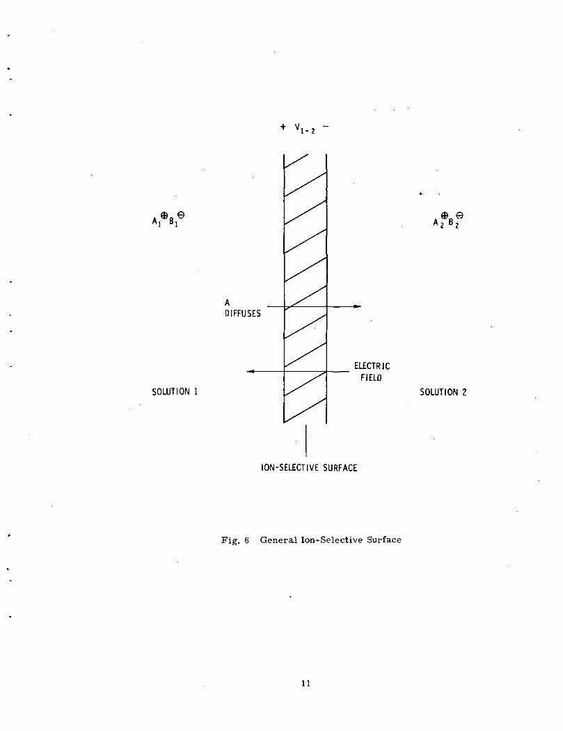
Let us consider a situation as shown in Fig. 6. An ion-selective surface is •
interposed between two solutions of different concentrations of a salt A B . Let us
assume that the surface will pass only the positive ions, A . If the left side con-
centration, A1 , is greater than the right side concentration, A, , the diffusion
law states that ions will move from left to right. B~ ions would also flow by diffu-
sion until the concentrations were equal, but are stopped by the membrane. After
a very short period of diffusion flow, the migration of A will leave a net negative
charge on the left side and build up a net positive charge on the right side. A
charge separation such as this will automatically have an associated electric field
vectored right to left. This field will oppose further migration of positive ions,
resulting in an equilibrium position. Since the diffusion forces driving positive
ions is clearly a direct function of the concentration ratios, so will be the resulting
potential. The actual form of this dependence is derived by Eisenman in his work
on glass electrodes; the simple form is as follows:

GLASS ^ELECTRODE
INTERNALFILLINGSOLUTION
*
X
+ E
SOLU1UNDER
"IONTEST
1
Ag-AgCI., ELECTRODES ,
*.
\ /
REFERENCEELECTRODE
SATURATEDKCI SOLUTION
ION-SELECTIVE SURFACE LIQUID JUNCTION
Fig. 5 Ion-selective Sensor System
10
' 1 -2
ADIFFUSES
SOLUTION 1
DA B2 2
ELECTRICFIELD
SOLUTION 2
ION-SELECTIVE SURFACE
Fig. 6 General Ion-Selective Surface
11

V
1-2
n
R
T
F
1-2
= potential across membrane from left to right.
= ion charge number.
= gas constant.
= absolute temperature.
= Faraday's constant.
= activity of ion.
The first important point is that the electrodes respond to the activity of the
ion, rather than the concentration in that they are equivalent at low concentrations_ 2
(less than 10 molar total solution ionic strength), but the activity becomes a
smaller and smaller fraction of the concentration as it increases. The functional
dependence is complex and depends not only on the concentration of that ion but also
on all other species in the solution. But since it is the activity rather than the total
concentration of the ion which determines the effect the ion has on various physio-
logic functions, this sensor actually measures a more important quantity. For
measurements of parameters in normal physiologic fluids, the activity coefficients
are sufficiently well known so that correlations can be made to yield the concentra-
tion data.
There are several modifications which must be made to the above equation.
First, the electrodes do not respond exactly according to the slope factor RT/nF,
so an efficiency factor, rj, must be included. Another consideration when measur-
ing biological fluids is that they are multiple ion systems, and the electrodes are
not totally specific to a given ion. They are normally very selective for cations over
anions or vice versa, but may not necessarily be selective between two cations or4
ariions. Eisenman has shown that this can be accounted for by a simple linear
summation with coefficients. Also, in a real measurement system, one cannot
measure the isolated potential at the membrane surface, but must measure the
total potential of the electrode pair. This leads to the following functional relation-
ship :
V = E iRT In I_Ln.
12

E° = sum of constant potentials.
r) = efficiency factor.
K,. = specificity coefficient of species i.
n. = charge no. of species i.
a. = activity of species i.
All of the ion-selective sensors respond in the manner of the above equation.
Since the response is logarithmic, the sensors are reasonably accurate over a very
wide range, typically 3 to 5 orders of magnitude. The limitation on the range ate c
the low end is usually near 10 or 10 molar, and generally resulting from this
being the solubility of the sensor material in water. The limitation at the high end
is normally at 0. 1 to 1 molar, often because the activity coefficients vary widely in
this range, making correlation difficult.
The sensors can be classified into four types, each with their own particular
set of operational characteristics. The first type is the glass electrode, which
consists of a glass tip of special formulation to respond to the ion of interest.
These were the first sensor type invented, but they are limited to measuring pH,
sodium, and potassium or ammonium. They are characterized by very high elec-
trical resistance, reasonable stability, fragility, but very long lifetime if properly
handled, and good selectivity in the pH and sodium types. It is not likely that any
new sensors of this type will appear. The next type is the solid-state crystal
membrane. It consists of a solid crystal of very low solubility made up of the ion
of interest and an ion not generally of measurement interest; for example, an
AgCl crystal will measure chloride, silver not normally being present. These are
available for fluoride, chloride, bromide, iodide, sulfide, copper, lead, cadmium,
and a few others. They are characterized by relatively low electrical impedance,
good stability, ruggedness, very long lifetime, and variable selectivity. They are
easily the best performing sensor type. However, it is not likely that many new
sensor types beyond those already discovered will be found since it is a matter of
finding proper crystalline compounds, and the list has been thoroughly searched.
The third type discovered is the liquid membrane system first described by Ross
in 1967 . A thin hydrophobic membrane is placed between the reference inner
solution and the test solution. An organic solvent containing a specific complex
organic carrier is applied at the edge of the membrane and soaks it. The organic
carrier compound is selected to be specific for carrying only one ionic species.
All other ions are repelled since the membrane is hydrophobic and therefore rejects
polarized materials. Thus the ion-selective and potential-producing character is
achieved. They are available for a very wide range of ions, notably calcium,
13

potassium (more selective than glass), magnesium, copper, lead and nitrate. They
are characterized by moderate electrical impedance, poor stability, difficulty of use,
short lifetime, and good selectivity. They seem to show the most promise for dis-
covery of sensors to measure new parameters because of the very large number
of potential organic carrier systems. A fourth type which recently appeared is the
heterogeneous membrane type. It includes a very broad class of sensors presently
in the research phase. In general, they consist of a support mechanism of some
sort such as a silicone rubber, paraffin or epoxy which suspends the ion-selective
material and perhaps a silver salt or other system to maintain a low electrical
resistance. Systems of this sort have been developed for calcium, potassium,
sulfate, iodine, and a few others. Commercially available models of these sensors
have not gained wide acceptance, but we have not studied any. The research, which
is discussed by Covington in the NBS publication, would indicate that there are both
stability and lifetime problems with these sensors. However, Covington concludes
that there is good potential for both improved models of current sensors and also
new sensor types.
14

SECTION 4
STUDIES ON ION-SELECTIVE SENSORS
The investigation of ion-selective electrodes has been conducted with the aim
of finding suitable sensors for several biomedical applications, including discrete
sample analysis and on-line monitoring of flowing fluids, notably blood. We there-
fore have adopted several sets of criteria in evaluating sensor performance, and
our experience reflects this.
Before we could begin real evaluation, we discovered problem areas initially
in electronics and then in the reference electrodes. The problems are described
in other sections. We are now proceeding with some confidence that these problems
are under control. Furthermore, we have in this initial overview determined that
the problems of the sensors themselves are far more difficult than those so far
encountered and seemingly conquered, but these problems are nevertheless also
soluble.
The next problem encountered is that the electrodes require very tight
temperature control of the sensor, the reference, and the sample to achieve
accuracy and reliability. The slope factor, r^RT/nF, changes directly with absolute
temperature, an effect which varies depending on the ratio between the internal
reference solution and the test solution, having no effect at unity ratio. One nor-
mally fills the sensor with a solution near those to be encountered to minimize this
effect. More important is the fact that the E term in the sensor equation will
change enough with temperature to give significant errors for changes over + 0. 5 C.
This problem varies from unit to unit and is not well understood. Thermal cycling
over 5 C can cause irreversible changes in the glass structure which leads to a
hysteresis in readings. We were therefore compelled to construct a heated jacket
system for all electrode test chambers for control to ± 0. 1 C.
The initial experience has been with the small glass sensors marketed by
Beckman, the clinical sodium sensor, type 39046, and the clinical cation sensor,
type 39047. The cation sensor is appropriately named in that it is nearly equally
sensitive to potassium and ammonia, and about ten or twenty times less sensitive
to sodium. The sodium sensor is at least 1000 times more sensitive to sodium than
any other ion except silver, which may be neglected in biological systems since it
15

precipitates as AgCl and is therefore not ionized and not measurable. These glass
sensors, as well as the normal glass pH sensor have thin hydrated layers on the
internal and external surfaces of the sensitive glass tip. Because of the nature of
the glass structure, these hydrated layers act as ion exchange surfaces with inter-
stitial sites which can accommodate ions of the proper size, thus giving rise to
their measurement potential.
The hydrated layers are supported by the bulk of the glass membrane, which
does not participate in the measurement. However, this glass bulk acts as a very
high resistance (glass being an insulator) in series with the potentials developed at
the surfaces, thereby giving rise to the characteristic very high source resistance
of the sensor. The manufacturer can make the glass very thin to reduce this
resistance, but at the expense of producing a very fragile sensor tip. Also the
hydrated glass very slowly dissolves into the test solution, so that, even not con-
sidering fragility, a very thin sensor would have reduced lifetime. As a result,
it is difficult to make reliable bulk sensors with a thickness less than 0. 2 mm.
The resistance of the sodium sensors at room temperature varies from unit to unit
in a range of 2 X 10 to 10 ohms, but at body temperature of 37°C, they are more
manageable 50 to 200 megohms. The cation sensors are better, 50 to 100 megohms
at 23°C, and 5 to 10 megohms at 37 C. This required special instrumentation to
measure the sensor potential. This instrumentation has been developed, so that the
high impedance is now a problem only in that the response is slow. However, most
of the present problems with glass sensors are materials problems associated with
the hydrated surface layers.
There is an entire set of problems which could be described as operational
and which must be overcome before the sensor can either be studied or used in a
measurement. Some of these have already been discussed: temperature, sample
handling, reference electrodes, and electronic interface. The sensors also require
an initial stabilization period to bring the surfaces to the proper level of hydration.
The pH sensor stabilizes in about two days, a sodium sensor in two to five days,
but the potassium sensor can require two to four weeks. During this stabilization
period, there is a random drift in sensor potential which requires restandardization
with known solutions so often as to render the sensor virtually useless. Also, any
time even a well-stabilized electrode is inserted into a new measurement situation
or if the electronics interface is turned off and then on, there is an initial drift
period of perhaps thirty minutes. Much care must be taken to be certain that a
stabilized sensor is maintained wet in electrolyte solution; dehydration of the sur-
face will require another complete stabilization period.
After overcoming the above difficulties, one can begin to study the accuracy
and stability performance of the sensors. The first observation, which is somewhat
16

misleading, is that gained when a sensor is left continually in the same fluid at
constant concentration. After perhaps 12 hours, the sensor drift settles down to less
than 1% per day on some units, even the cation sensors. This gives the false
impression that the sensor is very stable. However, if the concentration is changed
and then returned to the original value even after a few days of stable operation,
there is a small shift. (This is all done in a flow-through situation so that the
sensors are always wet). The magnitude of this shift is somewhat correlated with
the concentration ratio.
In a normal measurement situation, where we first use a standard solution,
then test solution, we have consistently been able to get 1% accuracy in routine
situations with well-stabilized sensors, both sodium and cation. However, this is
only a stability requirement of five minutes. We have had a limited amount of
experience with the sensors in an on-line measurement of guinea pig blood during
a perfusion experiment. The sensor readings are immediately inconsistent but
after an hour begin to give good readings. It is felt that the change from simple
electrolyte standard solutions to the complex blood chemistry situation causes a
potential shift which recovers slowly. However, the sensor surfaces were not
seriously impaired after eight hours in the blood stream.
At this point, we have decided that the glass pH and sodium sensors are
valuable in biological situations and deserve further development. However, the
glass cation electrode is unsuitable except in well-controlled situations of discrete
sampling where both the ammonium and sodium are either known constant or
negligible. The selectivity ratios of the cation sensor are not only small and thus
require compensating but they exhibit a slow drift in time, thereby rendering the
sensor ineffective.
The pH and sodium sensors are already readily applicable in discrete
sampling situations where frequent standardization can be accomplished. We feel
that we will soon be able to apply them to relatively short-term on-line monitoring
situations of less than four hours. However, considerable development is still
necessary to reduce the drift problems now encountered before they can be applied
in long-term monitoring situations where calibration is difficult, i.e., an
implant.
It is very likely that the drift observed is a combination of two effects, both
a result of materials handling. The first problem is that during the cooling, of the
glass, strains are set up which effect the surface states in the hydrated layers.
Since glass has a very slight fluid character, and since the hydrated surfaces are
slowly but continually dissolving into the solutions, these strains slowly shift and
alter the surface states. Sudden changes in the electrode environment also induce
17

new strain on the surface. The other problem is that the sensor properties are
highly sensitive to composition changes. If the glass is inhomogeneous, as the
surface slowly dissolves, a different composition will appear at the surface, thereby
giving a different potential. There may also be some merit to considering surface
treatments, either to reduce strain or to retard the leaching process. In any case,
it is our feeling that the materials technology is available which can bring these
sensors to the point where they can be implanted with confidence that they will
exhibit long-term accuracy. Biological compatibility is another matter which will
be considered later.
Because of the failure of the glass cation sensor to reliably measure
potassium, we searched for a replacement. In the Fall of 1970, Orion Research+4announced a liquid membrane sensor with a rejection ratio of over 10 with
respect to sodium and approximately 100 with respect to ammonium ion. The
organic carrier is a form of valinomycin. We purchased one of these sensors and
have given it a brief trial to determine the feasibility of its use in various applica-
tions.
A schematic of the construction is shown in Fig. 7 . The acetate filter disc
is given a hydrophobic treatment, which prevents direct exchange between the test
solution and internal reference solution. To use the sensor one must assemble the
sensor by squeezing the small filter disc between the internal body and the external
sleeve, introducing the two filling solutions and then inserting the central AgCl
electrode. Sensor performance seems to revolve around the quality of the filter
disc. Initially, with a good disc, the sensor will give as much as a 56-mv potential
difference ifor a decade activity change (theoretical is 60 mv). The distribution runs
from about 45 mv to 56, 53 being normal. In use, this response slope degrades to
virtually zero in anywhere from one to three weeks. The internal materials slowly
leach into the test solutions, but do not run out unless the sensor is assembled im-
properly and allows a slow leak. We therefore concluded that the membrane con-
dition is critical. This is preliminary, and we are conducting further tests.
The electrical resistance of the sensor is on the order of 50 megohms at
23°C and goes down to about 10 megohms at 37°C, so that they are less fragile
electrically than the glass sodium. The response time is reasonably rapid,
approximately 15 seconds for doubling or halving the concentration at a level_ 3
around 10 molar. The speed is a direct but not linear function of concentration
being faster at high concentration. The short-term drift rate is far worse than that
of a sodium sensor, on the order of a few percent in ten minutes. One advantage of
this sensor is a much shorter initial stabilization time; it will achieve its maximum
performance in at most four hours, and can be easily used within an hour after
assembly.
18

AgCI ElfCTRODE
EXTERNAL SLEEVE
SENSINGSURFACE
ACETATE FILTER DISC
INTERNAL REFERENCE SOLUTION
INTERNAL BODY
\
EXTERNAL ORGANICFILLING SOLUTION
Fig. 7 Liquid Membrane Sensor
19

We have concluded that this sensor is suitable for discrete sample analysis
and some forms of short-term, on-line monitoring. The nature of its present form
is not suitable for an implant, however. There are three reasons for this. First,
the stability of this sensor is at least two orders of magnitude away from that
required for a long-term noncalibrated situation. However, this is a new sensor
whose performance can undoubtedly be improved; the glass sodium sensors are
much better now than when first reported by Eisenman in 1957. Second, the short
lifetime of at most three weeks must be improved considerably but is very likely a
matter of design. Third, the presence of a very slow leaching of the valinomycin
and its strong organic solvent would very likely cause considerable irritation at
the implant site, thus possibly causing large shifts in the local chemistry — and
perhaps of the entire organism. The most fruitful direction to take for solution of
all of these problems will undoubtedly involve a search for a sensor tip which
retards the leaching of the internal solution or in fact stabilizes it in some matrix.
Beckman has a sensor of this form, but it has a very short lifetime. We will also
try forms of dialysis membrane external to the sensor which will allow electrolyte
exchange but blockage of larger organic compounds. Several tradeoffs are involved,
the major ones being sensor accuracy and response rate. However, again we feel
that this is a materials problem which can be overcome, although this is probably
a more difficult problem than the glass sodium sensor.
We have also done a small amount of work with the solid-state crystal
sensors. We have used an In Vivo Metrics Ag-AgCl bulb sensor for measuring
chloride and an Orion Model 94-09 with a lanthanum fluoride crystal for fluoride.
Initial studies have shown that both types are very stable and excellent for this
application. The electrical resistances are under one megohm, mainly because the
crystals are ionic lattices capable of supporting conduction. The crystals dissolve
very slowly into an electrolyte solution. This does not affect sensor lifetime, which
is apparently indefinite, but differing inhomogeneities in the crystal structure are
revealed to the test solution, thereby causing a slow drift. Process control to
reduce material impurity and to reduce crystal defects will undoubtedly bring
sensor performance to the quality required for an implant. The problems of the
biological interface must still be considered.
20

SECTION 5
REFERENCE ELECTRODES
A necessary element in all ion-selective measurement systems is the
reference electrode. Since the measured parameter is the electrode voltage, it is
clear that two electrodes are required to complete the electrical circuit. The
second electrode, the reference, should maintain an absolutely stable potential in
the sample fluid, independent of fluid changes, flow rates, or temperature changes.
At first glance this may seem simple; all that need be done is to insert a wire into
the solution. However, complex physical phenomena occur at metal surfaces in
electrolyte solutions which generate reduction-oxidation potentials. These poten-
tials vary considerably with time as the surface state of the metal changes under
reaction with the solution. In fact, the only surfaces which give reliable, relatively
stable potentials in electrolyte solutions are in fact forms of ion-selective electrodes.
Furthermore, if one could rely on a given ionic species as having an absolutely con-
stant concentration even though others vary, the best reference would be an electrode
selective to that species. However, that situation seldom exists, especially in bio-
logical materials.
As a result of all of the above constraints, virtually all measurements employ
as a reference the liquid junction system, as shown in Fig. 5. In this technique, a
highly stable ion-selective electrode (usually AgCl or HgCl0) is placed in a com-zpartment which is absolutely stable in the species it measures (usually a saturated
solution): this compartment is then connected to the sample solution by some form
of restricted liquid connection, the concept being to have a merely resistive and
nonpotential generating connection between the two liquids. With proper design,
stable potentials can be achieved with the above technique. The major difficulties
arise in trying to achieve the proper form of liquid junction, because, unfortunately,
there must be a finite fluid flow with associated ionic flow (if not, there is poor
electrical connection), and net ionic flow will generate a potential. This potential
is predictable from the integrated Nernst-Planck equation:
E = RTlnF in
n
1= 1n
. 1 = 1
Kis Uis ais
Kis Uis ais
21

R = gas constant
T = absolute temperature
F = Faraday constant
K. = partition coefficient of charged species iIS
U. = mobility in flow region of species i
a' = activity of species i in external phaseIS '
a." = activity of species i in internal phaseIS
The use of the equation is not possible in any normal situation because many
of the ionic flow rates cannot be determined. But years of experimentation have
shown that the best reference electrodes employ an absolute minimum flow rate in
a symmetrical flow pattern. It is also helpful to use an electrolyte filling solution
whose positive and negative ion carriers have similar diffusion coefficients.
The two major types of internal electrodes are Ag-AgCl (silver chloride
deposited on silver wire) and the calomel (an amalgam of mercury and mercurous
chloride). The calomel has historically been more popular for wide-range general
chemistry use in pH measurement probably because it is cheaper. But the calomel
is unstable and subject to hysteresis with temperature changes, and if a sensor
were to fail in an implanted situation, the mercury would prove highly poisonous.
We have, therefore, considered only the silver chloride internal reference.
The next problem to consider is that of the liquid junction. Our first
response was to investigate the various commercially available types. Two major
firms in this area for several years are Beckman and Corning; their reference
junctions are somewhat the same in that most employ some mechanical means to
produce the restricted flow in a short tube. The general practice is the use of a
small hole about 1 mm in diameter, 3 to 4 mm long, which is filled with a semi-
porous material, such as a packed fiber, a glass frit or a porous ceramic plug.
Almost all of these tend to clog in time by crystallization in the plug; althoughsome units [can be recovered by boiling in nitric acid. The flow in the junction
is not well-controlled so that erratic potentials result and the filling solution
needs to be replenished rather often. All of these solutions were rejected.
A relative newcomer in the field is Orion Corporation. Their reference
electrodes use two concentric pieces closely machined to produce a tight-fitting
cone at the bottom, as shown in Fig. 8. The reference fluid flows by capillary
action to establish the liquid junction. This type is far superior in that it is easier
to use, more durable, and easily recovered even if allowed to dry out completely.
The electrode typically given has potentials reproducible to ±0. 2 mv. The major
22

MACHINEDCONE
SATURATED KCI SOLUTIONAgCI INTERNAL ELECTRODE
Fig. 8 Orion Reference Electrode
23

problems with them are that they are large (1/2" diameter by 5" long) and can have
a high rate of electrolyte flow, making them unsuitable for implant work. However,
they are among the best available for general laboratory work.
Development Work on Reference Electrodes
Upon discovering that there are really no commercially available reference
electrodes which can be directly applied to an implanted ion sensor system, we
began a search for other techniques. It was soon discovered that very good poten-
tial liquid junction would be dialysis tubing used for artificial kidney equipment.
This type of material readily passes small ions and water while restricting bulk
flow as well as large molecules. In use, it takes up water and swells to create a
structure of small pores. A few configurations were tried, with the one shown in
Fig. 9 and 3 being a final version. The inner sleeve has a 1-mm hole drilled through
the center in the end. The dialysis membrane is stretched over the end of the
sleeve and is pulled tight and sealed with the outer sleeve, which is drilled for a
tight fit. Assembly is performed in a bath of electrolyte to be certain that the
small end hole is wetted and free of bubbles. An Ag-AgCl electrode is then inserted
in the center. The electrode must then be soaked for about two days in an electro-
lyte solution to allow the membrane to swell properly and establish proper flow.
The membranes can be presoaked but are more difficult to handle and likely to tear
during assembly. References of this type have been used reliably in measurements
with ±0. 1-mv reproducibility. The membranes have lifetimes approaching six
months, and the electrolyte loss is such that the sensors need be refilled only once
a month at most. A quantitative study of the sensors investigating parameters of
the membranes, hole geometry, or filling solutions has not been undertaken, mainly
because the first model was satisfactory.
Although we have attempted no theoretical study of the sensor performance,
it is felt that the high degree of symmetry as well as the very abrupt nature of the
junction, combined with very low flow rate,. are the major factors which contribute
to the superior performance. We feel that it can be readily adapted to an implant
situation. The surface material, dialysis membrane, has already been proven in
biological applications. Also, the sensor is easily miniaturized and can operate for
long periods without maintenance. Continued study will be required to be certain of
long-term tissue reaction as well as the above-mentioned parameters in order to
optimize performance, but it is felt that this sensor type will be the proper one to
employ.
24

SATURATED KCI SOLUTION
DIALYSISMEMBRANE
OUTER SLEEVE
AgCI ELECTRODE
INNER BODY
Fig. 9 Dialysis Membrane Reference Electrode
25

SECTION 6
THE BIOLOGICAL INTERFACE
There are several problem areas relating to the biological interface which
must be studied in order to achieve a successful implant situation. Our literature
search has revealed an outline of these areas, as well as suggesting research
directions. We are concerned with this interface in two respects: first, the bio-
logical fluids and rejection mechanisms may coat the sensor or otherwise render it
ineffective; second, the foreign surfaces or fluids of the sensors or even their mere
presence may alter the local or total chemistry of the organism to a point that any
measurements are invalid.
Several different investigators have found that bare glass surfaces of any
nature will immediately absorb protein from solution so that a nonporous coating.
is built up. It has also been found that these coatings will build up on the surfaces
of the sodium and pH-type glass sensors and render them ineffective after perhaps
24 hours. There is a variety of possible approaches to these problems. Some
investigators have found that heparin binding or silicone coatings have reduced the
coating problems considerably, but this has not been tried with the sensors. Such
coatings may alter the response considerably. Others have shown that vacuum
degassing of glass surfaces reduces their biological interference. Another possible
solution is the use of dialysis membrane as an interface which passes the ions to be
measured but does not pass the larger offending protein systems. Ross has reported
that this is absolutely necessary for the liquid membrane potassium sensor since the
serum proteins render the sensor ineffective in a short time (see Appendix A). The
use of a membrane of a material similar to dialysis membrane would seem to be the
solution with the greatest potential, but considerable study is still required. Perhaps
a combination of solutions will be the optimum, but a considerable amount of research
is still needed to resolve the surfaces problem. Solving these can improve the areas
of discrete sample testing and on-line monitoring, considerably.
The other part of the problem is that of minimizing the trauma and tissue
reaction associated with foreign body rejection mechanisms. Studies we have found
show that disc-shaped objects placed in areas of low movement show the greatest
promise, but there is still a need for investigation. Very little research has been
27

done on local effects on the interstitial chemistry. It is our feeling that the most im-portant development in this area will be to minimize the size of the sensor as much
as absolutely possible and to maintain uniform surfaces. But we also feel that the
major portion of the research in this area will involve implantation of devices into
normal, healthy subjects and observing the results, both locally and systemically.
28

SECTION 7
ELECTRICAL INTERFACE CIRCUITRY
One of the first problems encountered in the development of an implantable
electrochemical sensor system was the stringent requirement imposed on the elec-
tronics interfacing with the sensor. The sensor is essentially a dc source with a
source resistance up to 100 megohms, which must be measured to an absolute accu-
racy of better than 50 pv on a long-term basis. This means that the circuit must
have a low offset voltage and a very low input bias current, less than 0. 5 pa. For
the implantable situation, it is also desirable to have a minimum power requirement
to allow battery lifetime of at least a few weeks. Considerable work has been done
in this area, and a circuit capable of performing this function has been developed.
The initial design for this amplifier was undertaken by Mr. David Kress and
reported in an unpublished Master's thesis. The latest version of the design was
developed by Mr. Kress for this project.
A block diagram of the circuit is shown in Fig. 10. It is chopper-stabilized
to insure very low offset voltage drift. Present direct-coupled FET input amplifiers
exhibit drifts of 50 to 100 \j.vl C, and long-term drifts in hundreds of microvolts.
The drawback, of course, with most chopper systems is high input bias current and
a requirement to operate inverting, which severely limits input impedance. In order12to achieve very high input impedance, typically 2 X 1 0 ohms, a noninverting chopper
system was used, whereby a unity-gain feedback system signal is compared with
the input signal to drive the system to a null at the chopper. This clearly gives very
high input resistance, since at null there is no voltage drop across the MOSFET
switch pair and thus no current. The input terminal sees only a capacitor and the14MOS gates as leakage paths, both of which are over 10 ohms for properly selected
units.
The major leakage components in this situation are actually the transients
associated with the switching of the MOSFET pair. If the transients are not matched,
there is a net charge transfer on each cycle which then leads to a net leakage current.
This is definitely an ac effect since the leakage increases linearly with frequency.
This leakage can be nulled out by using a trimming capacitor. However, this does
29

INPUT •- uCHOPPER
LJ
OSCILLATORand F/F
OUTPUT
SYNCHRONOUSCOMPARATOR
INTEGRATOR
Fig. 10 Block Diagram
30

not help input impedance; even though the leakage can be trimmed to less than 0.1 pa
at a given input voltage, it will vary as the input changes. |The reason for this,
as discovered, is that the MOS transistors have capacitances which vary with the
voltage applied across them. Since the level of the switch must vary with the input,
the voltage across the gate will vary if the drive voltage is referenced to ground.
Therefore, the capacitances which were balanced at one input level will be unbalanced
at another level, therefore giving rise to a net transient again. The solution for
this problem was to float the oscillator voltage supply referenced to the unity gain
output so that the relative gate voltage is constant. Implementation of this system12immediately led to an input impedance well over 10 ohms, the design goal. This
technique also led to a great improvement in common-mode rejection ratio of 110 dB.
It is felt that this model will not perform well over a wide temperature range as
designed, partly because the oscillator frequency is not well stabilized, but this
is not critical since the device will be used either in a laboratory environment or in
vivo at the well-controlled 37°C body temperature. However, such stabilization
could very likely be designed in. Long-term drift tests of a few weeks have shown
offset voltage drift of 1 to 2 /jv, and offset current drift of ± 0. 5 pa. Preliminary
temperature drift studies show a typical drift of ± 0. 25 nv/°C and ± 0. 3 pa/ C with
no hysteresis.
The circuit operation can be followed from the block diagram of Fig. 6. By
alternately switching on the MOSFETs in the chopper, an error signal is formed,
e(t), which is a square wave between the input and the output. It is fed into the12source follower which has an ac input impedance of 10 ohms over a wide range
of input. This signal then goes to a very high gain, (about 30, 000) ac-coupled
amplifier. This amplified square wave is then demodulated by going through a
comparator in a synchronous connection. According to the phase of the chopping
cycle, the square wave and ground potential are alternately switched from the
positive to the negative input terminal so that a finite error signal can be detected,
resulting from the output being high or low. The output of the comparator drives
an integrator which is essentially a very low pass filter. At null the output of the
integrator matches the input, and all signals will theoretically go to zero; noise vol-
tages keep the comparator section oscillating at null, but the integrator removes
this noise. One note, however, is that most circuit functions are handled by the
Solitron UC4250C type amplifier which will operate on ±1. 35 volt supplies at 5 pa
supply current. The present system uses ±1. 35 and -2.1 volt supplies, the increased
low voltage necessary to ensure turn on of the MOSFET devices. With lower
threshold devices, the system should be able to operate with ±1. 35 volt supplies. ' '
Supply current in the present system is 25 /ua, but it is felt that improved design
will bring this under 10 ua.
31

SECTION 8
CONCLUSION
The state-of-the-art technology required to develop an implantable biotelemetry
ion detector can be roughly divided into the electronic and sensor areas. The elec-
tronic area is primarily concerned with the high impedance interface, data encoding
data transmission and data storage. Most of the electronic effort performed for this
contract was concentrated in developing a high impedance interface circuit which
required low power and was capable of being miniaturized. The circuit described
in the report satisfied these requirements and could be hybridized into a suitable
package.
The vast advancements made in solid-state technology over the past few years
enable the electronic problems to be solvable with existing state-of-the-art know-
ledge. After a suitable electronic system is developed, miniaturization can be
accomplished by existing techniques. The techniques chosen will depend on the
application of the biotelemetry ion detectors and the number of systems to be built.
As an example, if a large number of systems were to be built, maximum use would
be made of monolithic silicon circuits developed especially for this application. If
only a few systems were to be built, a hybridized structure using existing semicon-
ductor chips would be the best approach. The electronic area is an engineering
problem related to cost and application. The sensors required for a biotelemetry
system are not off-the-shelf available, so that a greater portion of the contract was
devoted to an evaluation of sensors.
This report has discussed the state-of-the-art and potential applications of
a new class of sensor, the ion-selective electrode. At this point they show promise
for use in a variety of biomedical applications, from the use in an implant for
continuous monitoring without the problems of sampling collection, to routine high-
volume testing in the hospital chemistry lab. The sensors, which cover at least
75% of the tests routinely performed in both research and clinical situations, have
not yet been extensively applied because of a group of problems we have outlined.
They have been applied successfully in many research situations where highly
qualified technicians with considerable experience in the use of the sensors did the
measurements. However, it is felt that the inherent potential of the concept of a
33
contact sensor requiring no moving parts, complex dilution and mixing apparatus,
or very accurate photocell systems more than warrants continued development of
these sensors to bring them into the realm of routine application.
In their present form, the sensors can be used in both discrete sampling and
on-line monitoring systems which are properly designed to overcome the shortcomings
of the sensors. The major problem is that of drift rates, which means that frequent
calibration is required, either automatically or manually. The second problem is
that a replacement cycle is necessary, especially for the liquid membrane sensors.
With the present sensors, on-line equipment can be designed which can give up to
one-half hour of monitoring over a small concentration range of perhaps 20%.
Initial improvement in the sensors would allow design simplifications as well as
performance improvements of any type of this equipment.
The sensors in their present form cannot be applied to implant situations.
However, with development in the areas discussed, we feel that they can be applied
in implants. The commercial suppliers of these sensors have not done this develop-
ment and are not likely to because it would not appear too economically attractive.
The sensors have sold but not in volume, so that they are not convinced that in-
creased investment will be economically attractive. This we conclude since all of
their advertisements and descriptive brochures point out the potential of the sensors,
as we have, without pointing out the difficulties. They seem to be concentrating their
efforts in marketing the sensors as they are in applications where they are useful
irt their present form. There is also a going research effort to expand the range
of ions which can be measured. Therefore, the development efforts we see as
necessary are in improving the present sensors to the point where they can be more
easily applied for both routine and demanding situations.
The ion-selective sensor system breaks down into four areas: the elec-
tronics interface, the sensor, the reference, and the biological interface. The
electronics interface problems are virtually eliminated in comparison with other
areas. For an implant, considerable miniaturization will be required along with
reliability tests, but this technology is readily available. For telemetry applica-
tions additional circuit development will be necessary, but again, this is currently
available technology.
The major development area will be in the improvement of the ion-selective
sensors. The glass electrodes are at a level where they have a satisfactory life-
time but a drift rate such that recalibration is necessary at least every eight hours
even for the best units. The problem is basically one of materials, first of producing
a material not subject to minor stresses which will change with time, and also of
producing an absolutely uniform structure whose properties will not vary as the
34

hydrated layer slowly leaches into solution. This is not a trivial materials problem,
but is one that can be solved. The liquid membrane sensors for potassium and
calcium will be more difficult since more components of a more complex nature
are involved. It is felt that the first area of concern will be the disc or whatever
saturable membrane is used in the tip of the sensor. This material is very impor-
tant in determining the lifetime of the sensor, its drift properties, and also the
biological contamination. Undoubtedly, this research program will be conducted
in conjunction with optimizing the solvent type and organic carrier. It is anticipated
that the liquid sensors will be a more difficult problem, but are worth studying
since they seem to offer the greatest promise for covering a wide range of measure-
ment situations. The third sensor type, the solid-state crystal, is perhaps closest
to being applicable in long-term implants since it already has the best drift perfor-
mance and sufficient lifetime. Some development will still be necessary to achieve
the reliability in the miniaturized form of the sensor. All sensor development
should proceed along the lines of attempting to achieve optimum performance in a
sensor of manageable size and then embarking on a program of-miniaturization.
Large versions of an optimized sensor can be immediately applied in other pressing
important situations where size is not nearly so critical.
The present state of the reference electrode is at nearly the same quality as
the electronics in that we have developed a reliable long-life probe suitable for use
in large-scale systems. Some development is still necessary to achieve the desired
miniaturization while preserving the reliability, but this should not prove to be a
major problem area.
The last problem area, the biological interface, will require considerable
investigation. Previous research has involved mostly observation of local histo-
logical effects and some study of the coating of various materials in vivo by various
subjects. Very little has been done on local chemistry changes, but this is clearly
very important to the application of implanted sensors. Much of this will be con-
ducted in conjunction with the sensor studies.
In short, we feel that the ion-selective sensor approach to measurement is
a very valuable one which deserves continued research and development. The
technique can be applied in several important research and clinical situations with
considerable improvements and proper equipment design, many of these applications
are close to implementation. The implantable sensor is still some distance from
application but the ion-selective electrode method is the only way this can be
accomplished. The sensors show sufficient promise so that with the proper devel-
opment, an implant can be done.
35

Page Intentionally Left Blank

REFERENCES
1. P. E. Bocget, C. M. Sliepcovich, and F. B. Bohr, Ind. Eng. Chem., 4 8 ( 2 ) ,
197, (1956).
2. Durst, Richard A., Editor, Ion-Selective Electrodes. National Bureau of
Standard Special Publication 314, U. S. Government Printing Office, Wash-
ington, D. C. , 1969.
3. Eisenman, George, Editor, Glass Electrodes for Hydrogren and Other
Cations, Marcel Dekker, New York, 1967.
4. Ibid.
5. Ross, J. W., Science 156, 3780(1967).

APPENDIX A
CATION AND ANION-SELECTIVE ELECTRODES
by
Peter P. Bradley
The literature in the fields of chemistry, biology, and medicine was
reviewed in the period from January 1969 to July 1970, in terms of relevant
publications to the present problem of developing electrodes for measurement of
cations and anions; in particular, sodium, potassium, and chloride, in biological
systems. The review attempts to elucidate the present trends in cation and anion-
selective electrodes of interest to us immediately (Na , K , and Cl"), .the appear-
ance of electrodes with new sensitivities, new techniques which are being applied to
electrode use, and applications of electrode technology in chemical, biological, and
medical experiments.
A. 1 Publications on Sodium. Potassium and Chloride-Sensitive Electrodes
The Orion Newsletter, August, 1969-Vol. 1, No. 3, reports an evaluation
of the potassium-selective electrode with valinomycin as the ion-exchange mem-
brane. It exhibits close to Nernstian slope, from 1 M to 10 M potassium, theK *7 s*i
limit of detection being between 10 and 10 M. The temperature range is 0-50 C.
Electrode resistance is less than 30 megohms. It is used with a double junction
reference electrode, Model 90-02. The selectivity constants are presented:
Monovalent Cation Selectivity Constant
Cs+ 1.0
NH4+ 0.03
H+ 0. 01
Ag+ 0.001
Na+ 0. 0002
Li+ 0.0001
Wise, et al. (1970) studied the Corning Model 476132 K ion-exchange+ + - *3electrode with a selectivity of about 80:1 for K over Na at 10 mol/kg. A cello-
phane dialysis membrane covered the outside porous membrane of the electrode to
prevent poisoning of the electrode. Reference electrodes used with it included a
saturated calomel electrode with a slow-leak fiber junction, and with serum, an
39

Ag-AgCl electrode covered with cellophane to keep the electrolyte filler from
diffusing into the medium. They found that this electrode is suitable for measuring
potassium concentrations in serum; it gave results which agree with those obtained
with flame photometry, without correction for sodium present in the normal concen-
trations.
Pearson and Elstob (1970) using a sodium ion-responsive glass electrode,
Electronic Instruments, Ltd. (E. I. L. ), type GEA 33, with a calomel reference
electrode equipped with a saturated KC1 salt bridge (E.I.L. type RJ23) obtained satis-
factory results with a variety of clinical solutions, excepting solutions of sodium
salts of weak acids and mixed solutions of electrolytes and dextrose, especially
after autoclaving which reduces the pH due to decomposition. In this case, it was
necessary to calibrate using a buffer system (0. 5 M triethanolamine + HC1 to pH 7) .
and dilute samples with the buffer before measurement.
Butler and Huston (1970) tested the Orion 92-19 K+ selective electrode for
activity responses. Systematic deviations from the Nernst equation were observed
in a direction opposite to the observed potential difference. These results indicate
that the ion exchanger is somewhat permeable to Cl" as
were found to be smaller if the ion exchanger was fresh.
that the ion exchanger is somewhat permeable to Cl" as well as to K . Deviations
Frant and Ross (1970) found that the Orion 92-19 K sensitive electrode
suitable for use with serum samples, since the values obtained agreed closely with
those obtained by flame photometry. The electrode, they reported, has a selectivity
over Na of 10, 000 to 1. The electrode is made from a 5 to 10% solution of valino-
mycin in an aromatic solvent, such as nitrobenzene, diphenylether, chlorobenzene,
or bromobenzene. The reference electrode was a double-junction with 5 M lithium
trichloroacetate filling solution.
Nutbourne (1969) tested the clinical applicability of sodium and potassium-
sensitive glasses BH 104 and BH 115, respectively, with a saturated KC1 calomel
electrode as reference. With the sodium electrode he obtained linear response,
and the effect of K , Ca , and Mg was negligible, as was changing the pH from
5 to 9. Values at least as good as those from the flame photometer were obtained.
He concluded that the sodium BH 104 electrode is suitable for work with serum and
urine.
The potassium glass electrode, BH 115, was tested with a saturated calomel
electrode, equipped with a salt bridge between the saturated KC1 of the electrode
and the sample. The salt bridge was as close to the composition of the sample as
possible. In constant Na solutions, he observed accurate response to changes in
K concentrations, but with changing Na , he observed a response in error up to
10 to 35%. The electrode was observed to be sensitive to Na and NH. . Thus, if
40

the concentrations of these ions are known or are zero, then the electrode may
adequately be used; but it is unsuitable for use in serum due to the Na and NH.
present, as it is in urine where these two ions lead to instability.
Mascini and Liberti (1969) report the fabrication of a halide-sensitive
electrode, the membrane of which is composed of Ag-halide and thermoplastic poly-
mer, fused together. Choice of halide confers specificity upon the electrode.
Response is reported to be good for solutions of single halides; deviation occurs in
mixed halide solutions. It was not evaluated in biological solutions. The reference
electrode used was a saturated calomel, fiber type (Beckman 39170).
Lai and Christian (1970) in evaluating the Orion 92-19 K selective electrode
found a slightly less than Nernstian response and a linear calibration curve which-4 -1 +was obtained from 10 to 10 M K . Slight anion effects are observed with I ,
OH", CrO.", and oxalate. The reference electrode used was a saturated KC1
calomel with a 3% agar-saturated ammonium nitrate salt bridge.
Krull, et al. (1970) is reported to have developed a solid membrane K
selective electrode. This publication is not available to us at present.
41

A. 2 Miscellaneous Publications on Patented Electrodes and Evaluation Studies
Fleet and Rechnitz (1970) utilized a rapid-mixing continuous-flow system
with liquid membrane ion-selective electrodes to measure reaction times as short
as 10 msec under turbulent flow conditions of complex formation of Ca , Mg
and Be with the biological ligands: lactate, gluconate, maleate, and tartrate.
Electrodes used included: Calcium Orion 92-20, divalent (Mg ) metal ion Orion
92-32-02 (with Be , equipped with an internal reference solution consisting of-3 2+
10 M Be in 1 M KC1). Reference electrodes were Orion How-through 98-20
or Beckman saturated calomel, type 39410, with a quartz fiber junction.
Whitfield and Leyendekkers (1970) studied the selectivity isotherms for the
Orion calcium-selective ion exchange electrode with the following system:
Ca(II)-Na(I)-Cl(I)-water. Variation in response was reported in the range 0. 03-6 M
as a function of solution composition as well as of ionic strength.
Settko and Wise (1969) report the fabrication of a liquid organic phase with± 2+ion-exchanging properties which can detect Cl or Ca
Cu++.
Ross (1969-1970) patented a cation-sensitive electrode which responds to
Ross (1969-1970) patented an anion-sensitive electrode which responds to
C1O4", Br", I", NO3", C1O3", and which is reproducible to 1%.
Ross (1969) patented several polymeric membranes (e. g., polyethylene) with
preferentially liquid transport paths between the organic phase (solid ion-exchanger
in organic solvent) and the test solution.
Rechnitz and Hseu (1969) found reduced interference by H and univalent and
divalent cations in analytical and biochemical measurements with a Ca selective
solid membrane electrode.
Pain and Mukherjee (1969) used bentonite clays to prepare electrodes
sensitive to Ca in the presence of high Na concentrations.
Frant and Ross (1969) patented electrodes for the determination of Cu ,
Cd++, or Pb++.
The following are the reference electrodes used in the first two parts of
this review:
With the Orion valinomycin 92-19, double junction, model 90-02.
With Corning 476132 potassium electrode:
(1) Saturated calomel with a slow-leak fiber junction for "pure" solution
work.
(2) Ag-AgCl covered with cellophane for serum work.
43

With E. I. L. sodium glass, type GEA 33, a calomel with saturated KC1 salt
bridge (E.I. L. type RJ23).
With Orion 92-19, Ag-AgCl filled with 0. 01 M KC1 saturated with AgCl.
With Orion 92-20, 92-32-02 (for Mg++):
(1) Orion 98-20.
(2) Beckman saturated calomel, type 39410 quartz fiber junction.
Whitfield and Leyendekkers used a Janaer thalamide reference electrode
(cat. 3183) with Orion 92-20 Ca and Orion 92-17 Cl.
Frant ar'1 Rose (1970) used a double junction reference electrode with 5 M
lithium trichloroacetate filler with the Orion 92-19 K selective electrode.
Scibona, et al. (1970) used a calomel electrode with saturated KC1 filler
with their alkylammonium salt electrode.
Nutbourne (1969) used a saturated calomel electrode as the reference
electrode (with a salt bridge in the case of the potassium electrode) in studying the
E.I. L. electrodes BH 104 (sodium) and the BH 115 (potassium).
With a halide-sensitive electrode, Mascini and Liberti (1969) used a
saturated calomel fiber type Beckman 39170 electrode.
Suga, et al. (1970) used an Ag-AgCl reference electrode filled with 1. 5 M
RbCl, with the microelectrode of NAS 11-18 (sodium-sensitive glass). With NAS
27-4 glass microelectrodes (potassium selective), they used the above NAS 11-18
glass microelectrode as the reference.
Pioda, et al. (1969) used a saturated KC1 calomel electrode with 0. 1 M NH4NO3
as the second solution of a double junction reference electrode with a valinomycin
system.
Lai and Christian (1970) used a saturated KC1 calomel electrode with a 3%
agar saturated NH.NO,, salt bridge with the Orion 92-19 K selective electrode.
44

A. 3 Publications on In Vivo Monitoring of Cation Concentrations
Suga, et al. (1970) measured the sodium and potassium concentrations in
vivo in the cochlear endolymph of the guinea pig. Endolymph, unlike most inter-
stitial fluid, exhibits high K concentration and low Na concentration. They used
microelectrodes to measure cation concentrations; for sodium, Corning NAS 11-18
glass capillary tubing; for potassium, Corning NAS 27-4 glass capillary tubing.
NaCl solution (0. 1 M) and 0. 1 M KC1, each buffered to pH 7. 6 by use of tris-
buffer, were used as filling solutions into which was suspended an Ag-AgCl wire.
In measuring activities, the NAS 11-18 glass microelectrode was used as the
reference electrode for potassium, since the NAS 27-4 responds to both potassium
and sodium. In the case of sodium, the reference electrode was a micropipette
filled with 1. 5 M RbCl, connected to an Ag-AgCl wire.
Friedman, et al. (1969) used the K glass electrode to monitor ion trans-
fers during the rewarming of the single rat tail artery.
Dick and McLaughlin (1969) measured Na and K activities and concentrations in
toad oocytes using Na and K sensitive microelectrodes and a flame photometer.
Glass Microelectrodes, edited by Lavallee, Marc, Schanne, Otto F., and
Hebert, Normand C., John Wiley and Sons, New York, 1969. Techniques are
described from which Suga derived his procedures. Discussed are "Single and
Coaxial Microelectrodes in the Study of the Retina", by Tsumeo Tomita, "The
Difference of Electric Potentials and the Partition of Ions Between the Medium and
the Vacuole of the Alga Nitella", by Gregor A. Kurella, "Cation and Hydrogen
Microelectrode in Single Neurons", by Raja H. Khuri, "Measurement of Activity of
Hydrogen, Potassium and Sodium Ions in Striated Muscle Fibers and Nerve Cells",
by P. G. Kostyuk, et al. It should be noted that the above research was completed
before 1968.
45

A. 4 Publications on Applications of Electrodes to Biomedical Fields
Webber and Wilson (1969) measured sodium concentration in high-purity water,
and obtained a Nernst-response down to 1 jug/liter Na , by controlling pH and
solution flow around the electrode.
Pioda, et al. (1969) found the valinomycin K sensitive electrode to have a
selectivity of K over Na of over 4, 000:1.
Mowbray (1969) evaluated a Corning electrode, with a greater sensitivity
for K than Na favorably for use as a biomedical tool..
Moore (1970) found that serum Ca concentration was within a narrow
range, 0. 94 to 1. 33 moles/1, and that within an individual varied 6% over several
months.
Scibona, et al. (1970) demonstrated that liquid membranes formed by
organic solutions of long chain alkylammonium salts behave as liquid electrodes
sensitive to the anion concentration. Liquid anion membranes can be used as
electrodes sensitive to the aqueous concentration of metal cation though anionic
complexes. Zinc and palladium were tested via their formation in the membrane
of tetrachlorozinc of tetrachloropalladium (II), these two species acting as anions
to the tetraalkylammonium salts. Both electrodes were Hg, Hg_Cl0, with saturatedLt £l
KC1 filling solution.
Fluoride
Tusl (1970) used an F~ electrode to measure F" concentration of diluted
samples of human urine, after adding sodium citrate to decompose Fe and Al
complexes.
Sun (1969) used F" electrodes with calomel reference to determine urinary
fluoride.
Manahan (1970) used the fluoride electrode as a reference in the determina-
tion of nitrate ion concentration with an error less than or equal to 0. 9%.
Jones, et al. (1969) used a fluoride-sensitive electrode to measure the
fluoride activity in buffered multi-vitamin preparations.
Francis (1969) determined fluoride ion concentration in products of decom-
position of organic materials.
Arnaldo and Mascini (1969) by means of added fluoride determined the
fluoride concentration by obtaining the equivalence point by Gram's Plot.
Anfalt and Jagner (1970) demonstrated that formate, acetate, proprionate,
and butyrate interfere with the precipitation reaction of fluoride with lanthanum
nitrates.
47

Calcium
LaCroix, et al. (1970) found that usage of the chloride ion electrode in
measuring chloride ion concentration of plant extracts resulted in unreproducible
and very high chloride concentration values.
Sodium and Chloride Ions
Kopito, et al. (1969) studied the use of electrodes in determining levels in
situ of sweat electrolytes in cystic fibrosis diagnosis.
Friedlmander, et al. (1969) utilized sodium electrode sweat tests in the
diagnosis of cystic fibrosis of the pancreas.
General
Kater and Leonard (1969-1970) patented the use of semipermeable membranes
to cover liquid junctions when used in biological fluids to prevent fouling of electrodes.
Montalvo and Guibault (1969) and Guibault and Montalvo (1969) coated NH.+
sensitive glass with urease and were able to measure urea concentrations due to
the resulting potential of the increased NH. .
Guibault, et al. (1969) used a Beckman electrode responsive to NH. in
monitoring of a deaminase system.
Guibault and Hrabankova (1970) coated electrodes with an L amino acid
oxidase and were able to determine the concentration of L amino acid by the
potential due to increased NH. which diffused into the electrode.
New Techniques of Determining Ion Concentration
Brand and Rechnitz (1970) developed a technique of differential potentiometry
with ion-selective electrodes, which does away with the weakness of the liquid junc-
tion. Two glass (or membrane) ion-sensitive electrodes are used, one sensing a
species which remains constant among all the samples tested. Manahan (1970)
used this method to measure nitrate concentration.
Bergveld (1970) developed an ion-sensitive solid-state device for neuro-
physiological measurements. The device combines the principles of an MOS trans-
istor and a glass electrode and can be used for measurements of ion activities in
electrochemical and biological environments.
48

A. 5 Publications on Biological-Glass Interfaces and Tissue Reactions To Implants
Button, et al. (1969) studied by reflected light microscopy and electron
microscopy the thrombi formed on a variety of foreign surfaces, including soda
lime silica glass, polymethylmethacrylate, and Epon epoxy resin. With histolo-
gical evaluation in two dimensions, they found that the thrombi are composed of
isolated cellular aggregates and an interaggregate red-cell fibrin mesh. In three
dimensions, it was found that the thrombi exhibited columnar-shaped cellular
aggregates extending from the foreign surface into the blood and red cell fibrin
mesh surrounding the aggregates. They concluded that since platelets were not
found adherent to the foreign surfaces directly, the intervening film "conditions"
the surface preliminary to platelet adhesion.
Johns son-Hegyeli and Hegyeli (1969) evaluated the compatibility of implant
materials in living cells in vitro. The materials and their interaction with living
human blood and tissue were observed. Blood cells-materials interfaces were
prepared by incubating the materials in contact with whole blood or platelet-rich
plasma. Tissue cell-materials interfaces were prepared by cultivating animal and
human cells as a monolayer directly on the surface of the material to be evaluated.
Implant materials included polymers, metals, glass, and carbon surfaces. Glass
coverslips implanted or studied in vitro were used as controls. Tissue and cell
growth were noted on the surface of the glass coverslips. Little toxicity or
"abnormal" growth was anticipated (or observed) with the glass coverslips as
controls.
Hersh, et al. (1969) bonded heparin ionically to glass surfaces. The heparin
coating resisted fluid shear stresses as high as 10 dynes/cm at 30°C for periods
in excess of 300 hours, and 1000 W of ultrasonic cleaning at 62 C for periods of more
than 45 minutes. The bonded heparin also prevents the clotting of human blood.
Heparin was linked via an amino silane to the surface of a borosilicate glass. They
found that physiologically significant amounts of heparin do not elute from the glass
surface into the blood.
Messing, et al. (1960) found that protein solutions exposed to porous glass
membranes are rapidly depleted of .protein. The proteins do not migrate through
the membranes but become trapped at the channel walls. The proteins, they found,
became firmly bound to the surface of the porous glass. Surface deactivation of
porous glass can be accomplished by treatment with methyl trimethloxysilane or
x-aminopropryl triethoxysilane, silanes which react with surface silanol sites to
produce a thin polysiloxane coating on the glass surface. The silane-treated
tubes remained permeable to water. The methyl silane treatment results in a
strongly hydrophobic coating.
49

Wood, et al. (1970) evaluated the significance of implant shape in experi-
mental testing of biological materials. In adult albino rabbits, they implanted a
number (304) of stainless steel discs and cylinders in the following sites: beneath
the periosteum of the anterior calvarium, under the masseter muscle of the left
mandibular ramus and in the body of the sacrospinalis muscle. Wood, et al.
compared the tissue reaction around the disc implants with that observed around '
the cylinder implants through the study of histological sections. In addition, the
degree of reactions observed at the various sites was contrasted with that seen at
the other sites.
They found that in all cases the muscle implants showed the greatest
reaction. Discs showed many "micro-areas" of tissue reaction around their
periphery. In contrast, the rod shaped implants in muscle demonstrated a greater
reaction towards the ends than in the mid-portion of the shaft (clubbing), but this
reaction did not occur with rods implanted at other sites. They concluded that
much of the histological tissue reaction observed around muscle implants is really
caused by mechanical trauma which must be differentiated from a noncompatibility
reaction. Thus, a site must be chosen where mechanical trauma will be minimal
(submasseteric site) and an implant shape must be employed which does not result
in clubbing (disc).
Rigdon (1970) demonstrated that when polyurethane was implanted subcu-
taneously in mice and rats, a chronic granulomatomous reaction occurs in which*
there is an excessive amount of hemosiderin ; the hemosiderin apparently results
from the lysis of the many erythrocytes present (some of which are partly creatina-
ted). He suggests that the infiltration of erythrocytes and subsequent hemolysis may
result from the positive change associated with this plastic, attracting the negatively
charged cells. A similar reaction occurs with nylon and Teflon. It is noted, how-
ever, that there is no significant amount of erythrocytes or hemosiderin associated
with the inflammatory reaction accompanying carbon black, glass beads, or Fuller's
earth.
Hemosiderin is an insoluble form of storage iron in which the small particles of
ferric hydroxide are so arranged as to be visible microscopically both with and
without the use of specific staining methods (Borland's Illustrated Medical
Dictionary, twenty-fourth edition, p. 665).
50

BIBLIOGRAPHY
1. Anfalt, T., and Jagner, D., Anal. Chim. , Acta, 50, 23 (1970).
2. Arnaldo, L., and Mascini, M., Anal. Chem., 41, 676(1969).
3. Bergveld, P., IEEE Trans. Biomed. Eng., 17, 70(1970).
4. Brand, M. J. D. , and Rechnitz, G. A. , Anal. Chem., 42, 616(1970).
5. Butler, J. N., and Huston, R., Anal. Chem , 42, 676 (1970).
6. Dick, D. A. T. , and McLaughlin, S. G. A., J. Physiol. (London)., 205.61 (1969).
7. Button, R. C. , Webber, A. J. , Hohnson, S. A. , and Baier, R. E., J. Biomed.Mat. Res., 3, 13 (1969).
8. Fleet, B., and Rechnitz, G. A. , Anal. Chem., 42_, 690(1970).
9. Frant, M. S. , and Ross, J. W., Jr., (Orion Research, Inc.) Ger. Offen.1,942,379 (Cl. GOln).
10. Frant, M.S., and Ross, J. W. , Jr., Science, 167, 987(1970).
11. Friedlander, S., et al., Calif. Med., 110. 367(1969) .
12. Friedman, S. M. , Palaty, V., Nakashima, M., Anal. Biochem., 29, 107(1969).
13. Guilbault, G. G., and Hrabankova, E., Anal. Lett., 3, 53(1970).
14. Guilbault, G. G., and Montalvo, J. G. , Jr., Anal. Lett., 2, 283(1969).
15. Guilbault, G. G. , and Montalvo, J. G. , Jr., Amer. Chem. Soc., 91, 2164(1969).
16. Guilbault, G. G. , Smith, R. K., and Montalvo, J. G., Jr., Anal. Chem.,41., 600 (1969).
17. Hersh, L. S. , and Weetall, H. H., J. Biomed. Mat. Res., 3, 471 (1969).
18. Johnsson-Hegyeli, R. I. E. , and Hegyeli, A. F., J. Biomed. Mat. Res., 3,115 (1969).
51

19. Jones, B.C., Heveran, J. E., and Senkowski, B. Z., J. Pharm. Sci.,58, 607 (1969).
20. Kater, J. A. R. , and Leonard, J. E., (Beckman Instruments, Inc.) U. S.3,498, 899 (Cl. 204-195 B Oik).
21. Kopito, L., etal., Pediatrics, 43, 794 (1969).
22. Krull, I. H. , Mask, C. A., and Cos grove, R. E., Anal. Lett., 3, 43(1970).
23. LaCroix, R. L. , Keeney, D. R., and Walsh, L. M., Commun. Soil Sci. PlantAnal., I, 1 (1970).
24. Lai, S., and Christian, G. D., Anal. Lett., 3, 11 (1970).
25. Manahan, S. E., Anal. Chem., 42, 128 (1970).
26. Mascini, M., and Liberti, A., Anal. Chim. Acta, 47, 339(1969).
27. Messing, R. A. , Weisz, P.P., and Baum, G., J. Biomed. Mat. Res., 3,425 (1969).
28. Montalvo, J. G., Jr., and Guilbault, G. G. , Anal. Chem., 41, 1897 (1969).
29. Moore, E. W., J. Clin. Invest., 49, 318 (1970).
30. Mowbray, J. H. , Biomed. Eng., 4_, 360(1969).
31. Nutbourne, D. M. , Anal. Biochem., 28, 326(1969).
32. Nutbourne. D. M., Anal. Biochem. , 28, 336(1969).
33. Okuda, M., etal., Jap. J. Clin. Path., r?, 503(1969).
34. Pain, B. K., and Mukherjee, S. K. , J. Indian. Soc. Soil Sci., 1/7, 209(1969).
35. Pearson, J. T. , and Elstob, C. M. , J. Pharm. Pharmacol., 2J3, 73(1970).
36. Pioda, L. A. R. , and Simon, W., Chimia, 23, 72(1969).
37. Rechnitz, G. A. , and Hseu, T. M. , Anal. Chem., 41, 111 (1969).
38. Rigdon, R. H. , J. Biomed. Mat. Res., J, 57(1970).
39. Ross, J.W., U.S. 3,438,886(1969).
40. Ross, J.W., U.S. 3,483, 112 (Cl, 204-195; B Oik).
41. Ross, J.W., U.S. 3,497,424 (Cl, 204-1; B Oik, G Oln).
42. Ruzicka, J., etal., Ann. Chim. Acta, 47, 475(1969).
43. Sachs, C., etal., Ann. Biol. Clin. (Paris), 27, 487 (1969).
44. Scibona, G., Mantella, L., and Danesi, P. R., Anal. Chem., 42, 844(1970).
45. Settzo, R. J. , and Wise, W. M. (Corning Glass). U. S. Pat.
52

46. Suga, F., Nakashima, T., and Snow, J. B., Jr., Life Sci., J3, 163(1970).
47. Sun, M.W., Amer. Ind. Hyg. Assoc. J, 30, 133 (1969).
48. Tackett, S. L. , Anal. Chem., 41, 1073(1969).
49. Tusl, J., Clin. Chim. Acta, 27, 216(1970).
50. Webber, H. M. , and Wilson, A. L. , Analyst (London), 94, 209(1969).
51. Whitfield, M., and Leyendekkers, J. V., Anal. Chem., 42, 444(1970).
52. Wise, W. M. , et al., Clin. Chem., 1_6, 103(1970).
53. Wood, N. K. , Kaminski, E. J. , and Oglesby, R. J. , J. Biomed. Mat. Res.,4, 1 (1970).
Addenda
Francis, H. J. , Jr., Microchem. J., 14, 580(1969).
Lavallee, Marc, Schanne, Otto., and Hebert, Normand C., eds., GlassMicroelectrodes, John Wiley and Sons, New York, 1969.
53