Embed Size (px)
Citation preview
Resource Publication 140
MAY 1981
I~
Fish and Wildlife Service
PROCEDURES FOR THE USE OF AIRCRAFT INWILDLIFE BIOTELEMETRY STUDIES
By David s. GilmerLewis M. CowardinRenee L. DuvalLarry M. MechlinCharles w. ShaifferV. B. Kuechle
UNITED STATES
DEPARTMENT OF THE INTERIOR
FISH AND WILDLIFE SERVICE
Resource Publication 140
Washington,D.C. .1981
Preface
Much of the knowledge and experience acquired by biologists who have used aircraftin biotelemetry studies has been inadequately documented. Procedures have beenlargely passed on by word of mouth between researchers. Consequently. little infor-mation is available in the literature to persons interested in these methods. In thepresent work we have attempted to assemble. in a logical sequence. guidelines that willaid the biologist who plans to use aircraft for tracking radio-marked animals. Theinformation provided here is based on extensive testing of equipment and methodsduring telemetry studies of waterfowl in Minnesota. North Dakota. and California. Al-though our experience has been primarily with waterfowl. we believe that most of theinformation presented here could apply equally well to biotelemetry studies of otherkinds of animals. Developments in new electronic technology .including the use ofsatellites for tracking animals ranging over vast areas. hold great promise for revolu-tionizing telemetry studies. However. these capabilities are not yet available to mostwildlife biologists. In the meantime. the methods described in this paper will provideguidelines for the use of aircraft in biotelemetry studies.

Procedures for the U se of Aircraftin Wildlife Biotelemetry Studies
by
David S. Gilmer,' Lewis M. Cowardin, Renee L. Duval,2Larry M. Mechlin, and Charles W. Shaiffer
U .S. Fish and Wildlife ServiceN orthern Prairie Wildlife Research Center
Jamestown, North Dakota 58401
V. B. Kuechle
Cedar Creek Bioelectronics LaboratoryUniversity of MinnesotaBethel, Minnesota 55005
Abstract
This is a report on the state of the art methodology and on questions that arise while one is pre-paring to use aircraft in a biotelemetry study. In general the first step in preparing to mount anantenna on an aircraft is to consult with a certified aircraft mechanic. Aircraft certification is dis-cussed to provide background information concerning the role of the Federal Aviation Admin-istration (F AA) in regulating the use of biotelemetry antennas on aircraft. However, approval ofany specific design of antenna mount rests with local F AA authority. Airplane and helicopter an-tenna attachments are described. Performance of the receiving antenna system is discussed withemphasis on how variables as aircraft type and antenna configuration may influence reception.The side-looking vs. front-looking antenna configuration and the VHF vs. HF frequency band aregenerally recommended for most aerial tracking studies. Characteristics of receivers, trans-mitters, and antennas that might influence tracking are discussed. Specific topics such as cali-bration of receivers and transmitter quality control are considered. Suggestions in preparing forand conducting tracking flights that will improve overall efficiency and safety are presented.Search techniques, including procedures for conducting large and specific area surveys as well asmethods to improve and evaluate search efficiency, are discussed. A concluding section considersspecial topics such as low-level operations and the use of helicopters. Diagrams of antennamounts, equipment check-off lists, and antenna test procedures are included as appendices.
Aircraft have played an important role in wildlifemanagement and research for over three decades(Crissey 1949), and are currently being used with in-creased frequency as a vehicle for tracking a wide va-riety of radio-marked animals (Cochran 1965, 1972;Graber 1965; Cochran et al. 1967; Kolenosky and John-ston 1967; Seidensticker et al. 1970; Mech et al. 1971;Dunstan 1974; Mech 1974; Hoskinson and Mech 1976;Kirby et al. 1976; Storm et al. 1976; Gilmer et al. 1977;Judd and Knight 1977; Weeks et al. 1977; Winter et al.
1978; Cederlund et al. 1979). The ability of an aircraftto rapidly survey large or inaccessible areas gives it anadvantage over other mobile tracking units. In addi-tion, the reception of radio signals from an airborneplatform is enhanced because of the nearly line-of-sight relation between transmitter and receiver .
Procedures for the use of aircraft in tracking opera-tions were described by Kolenosky and Johnston(1967), Seidensticker et al. (1970), Mech et al. (1971),Mech (1974), and Dunstan (1974). These proceduresdealt mostly with ways in which an aircraft can beequipped with receiving antennas and used to searchfor radio-marked animals. Optimum search proceduresare largely dependent on terrain and habitat featuresand animal mobility, as well as on equipment and typeof aircraft. Experience of the observer-pilot crew isalso an important factor (Hoskinson 1976).
lPresent address: Wildlife Research Field Station, U.S. Fishand Wildlife Service, Route 2, Box 5210, Dixon, California95620.
2Present address: U.S. Fish and Wildlife Service, Lloyd 500Building, Suite 1692, 500 N.E. Multnomah Street, Portland,Oregon 97232.
The intent of the present report is to supply biol-ogists with guidelines for conducting airborne bio-telemetry operations and provide a basis for makingdecisions regarding the installation of antennas, air-craft certification, telemetry system characteristics,preflight planning and safety considerations, searchtechniques, and methods for evaluating search effi-ciency.
Aircraft Certification
The form. which is usually prepared for a specific air-craft. describes how the equipment is installed and re-moved. what type of hardware is required. materialspecifications. and weight and balance data. The F AAGeneral Aviation District Office serving the areareviews these forms. If the antenna system meets pre-liminary F AA requirements. the mechanic is notifiedand requested to arrange for an F AA representative toinspect the installation on the aircraft.
If the installation passes the field inspection. anFAA Form 8130-7 is issued for the aircraft. certifi-cation of several aircraft should be requested. to insurethat an authorized aircraft is always available whentracking operations are scheduled. The pilot of the air-craft is usually responsible for insuring that all safetyand procedural requirements are followed wheneverthe antennas are attached.
If the F AA inspector feels that the antenna installa-tion is too complex to approve in the field and willrequire evaluation by F AA engineers. he will provideguidance on this procedure.
This outline of the sequence of events is provided sothat the biologist has some idea of the requirements.The important point is that the biologist should con-sult with a qualified airframe mechanic as the firststep in using telemetry antennas on any aircraft.
The ultimate purpose of the certification procedureis to protect the pilot and tracking crew. Should anaccident occur and the insurance inspector determinethat proper certification was not obtained. the insur-ance policy on the aircraft may be voided.
Aircraft owned. leased. or rented by the U.S.Government and by State agencies are considered"public aircraft'. and are not required to obtain air-worthiness certification for alterations caused bymounting tracking antennas. However. aircraft ownedand operated by the U.S. Department of the Interior(DOl) are required to obtain certification for altera-tions caused by mounting tracking antennas. Further-more. tracking installations on DOl aircraft aresubject to approval by the Office of Aircraft Services.We strongly recommend that the above certificationprocedures be followed. regardless of aircraft owner-ship.
Regulations governing aircraft certification proce-dures in foreign nations may be different from those inthe United States. Appropriate regulations or author-ities should be consulted in each situation.
Considerations for Antenna Mounting
The primary criterion for the design of a mount for abiotelemetry antenna on an aircraft is the develop-ment of a safe, secure system that satisfies airworthi-ness requirements. Of secondary importance is posi-
Most investigators conducting telemetry studies donot have access to permanently assigned aircraft butmust charter or lease available aircraft during the fieldseason. Consequently, it is desirable that a suitable an-tenna system be quickly and easily attachable to anaircraft without requiring permanent structuralalteration. It is imperative that the antenna andmounting bracket not interfere with aircraft controls,reduce the strength of the airframe, or adversely affectflight characteristics.
United States Federal Aviation Administration(F AA) Regulations require that any major alterationto an aircraft be accomplished in accordance with tech-nical data approved by the F AA Administrator. Twomethods of approval are (1) the Supplemental TypeCertificate program and (2) field approval by an air-worthiness inspector at a General Aviation DistrictOffice. Attachment of tracking antennas to an aircraftwould generally be considered a major alteration.However, it is possible that tracking equipment couldbe classified as a minor alteration depending on theshape of the antenna assembly, its weight, and place-ment. Aircraft with attached biotelemetry antennas,of the types described in the present paper were oper-ated in accordance with the terms of a Special Air-worthiness Certificate (FAA Form 8130-7) in the Re-stricted Category for a special use as described in F AARegulations 21.25 (2)(b). For biotelemetry operationsthe special use would be "Forest and Wildlife Con-servation."
When a decision is made to use aircraft in trackingoperations, several steps should be followed to obtainF AA certification of the aircraft. As a first step, thebiologist should consult with an F AA Certificated Air-frame Mechanic at a local airport (preferably the FixedBase Operator providing the aircraft) to discuss an-tenna requirements and the feasibility of mounting an-tennas on available aircraft. If the mechanic considersthe desired antenna system to be a minor alteration, heis authorized to approve the equipment for use on anaircraft.
If the antenna system is classified as a major altera-tion, the mechanic will prepare the appropriate request(F AA Form 337) for authorization of this alteration.

3
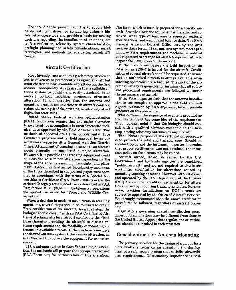
Fig. I. Correct position of side-looking yagi antenna mountedon a Cessna 172. Front quarter view (top), side view(bottom).
intake pipe to allow the cable to be retrieved throughthe air vent in the cockpit. If air intakes are not con-veniently located on the wing, the cable can usually berouted into the cockpit through a sliding window(Super Cub) or the door opening. If the cable is care-fully placed, the seal around the door usually does notcrimp the cable when the door is shut.
Cables should be routed into the cockpit and securedso that they do not interfere with the pilot's activitiesor the aircraft controls. An experienced person usuallyrequires only about 15 min to attach left and right an-tennas, route cables, and load equipment.
The design of an antenna mounting for a helicopterrequires additional considerations of the variable windand vibration forces that may exert pressure on themounted structure. The proximity of main and tailrotors to the antenna necessitates that the structurebe rigid and secure.
tioning the antenna so as to reduce any distortion toits directionality and sensitivity.
The size of the receiving antenna depends on the fre-quency and gain requirements of the equipment.Because higher frequency (VHF and UHF) equipmentrequires smaller antennas, it is more desirable for useon aircraft than low band (HF) equipment. Yagi an-tennas designed to receive signals at frequencies aslow as 140 MHz are practical for use on aircraft, butlower frequency yagis are often unwieldly and usuallyrequire loop antennas. Our experience in tracking froman aircraft is based primarily on 164 MHz equipmentwhich is commonly used in a wide range of telemetrystudies. Frequencies in this band are assigned to somegovernment a,gencies within the DOl, including theFish and Wildlife Service. The primary antenna de-scribed in the present paper is the yagi mounted in aside- or forward-looking configuration. Judd andKnight (1977) and Seidensticker et al. (1970) reportedon the use of a single antenna mounted through thebelly of an aircraft, and Whitehouse and Steven (1977)described a monopole array that can be permanentlyinstalled on aircraft.
To attach the antenna to the aircraft, we designed abracket that clamps to the wing strut of a high-wingedaircraft (high-winged aircraft were generally bettersuited than low-winged aircraft for tracking work).This design enables the user to mount the antenna onmost Cessna aircraft and to adjust the antenna in sev-eral axes (Fig. 1 and Appendix A). A simplified butless versatile mount was used on a Piper Super Cub.
Our antenna attachments were approved by thelocal F AA General A via tion District Office for specificaircraft. This approval does not insure that a similarlydesigned attachment would be approved by otherF AA offices or meet more restrictive F AA guidelines.
Brackets made of aluminum stock with heliarc weldswere attached by slipping the cuff over the wing strutand fastening it with bolts on the trailing edge of thecuff (Fig. 1 and Appendix A-1). Neoprene or naugahidepadding was used to avoid scratching the paint on thewing strut. The bracket must be correctly positionedby sliding it up and down the strut, before the bolts aretightened. The shaft can be extended or retracted asdesired after the bracket is secured.
On the basis of electronic tests, we considered theside-looking antenna correctly positioned when thetips of the middle antenna elements were about 15 cmbelow the leading edge of the wing and 30 cm forwardof the wing. Right and left antennas are positionedsimilarly unless variations are needed to achieve adesired effect, such as a combination of forward- andside-looking configurations.
Coaxial cables can be led directly from the antennato an air intake on the leading edge of the wing. Ascreen or filter may have to be removed from the

4
Fig. 2. Side- and forward-looking yagi antenna systemdesigned for use on a helicopter (Bell 206B Jet Ranger).Rear quarter view (top~. front quarter view (bottom).
The helicopter antenna mounting we used was de-signed for the Jet Ranger (Bell 206B) with high skids.It consisted of a single steel boom mounted forward ofthe fuselage. securely guyed and carrying both for-ward- and side-looking yagis (Fig. 2 and Appendix A-2). Coaxial cables were led into the cockpit through thedoor.
Performance of Receiving Antenna
Systems
The directional pattern of an antenna mounted on anaircraft influences the efficie~y and accuracy of track-ing. We determined antenna patterns only for yagi andloop antenna systems commonly used in biotelemetrystudies; tests of a wide range of receiving antenna
systems, such as dipole and monopole arrays (seeWhitehouse and Steven 1977) were not our intent.Furthermore, our test procedures were not conductedon an "antenna test range" designed for precise eval-uations. Costs required to insure elimination of allpotential errors are prohibitive. Nevertheless, webelieve that our results provide a basis for consideringthe characteristics of several antenna systems. Accu-racies of our measurements are well within tolerancesacceptable in field studies. We examined five principalvariables:
.Frequency-midfrequency of the transmitter-re-ceiver system (30 MHz loop and 164 MHz yagi).
.Aircraft type-make and model of the aircraft used(Cessna 172, Cessna 180 with floats, Piper Super CubPA-18}.
.Antenna configuration-antenna orientation withreference to the direction of flight (side-looking, for-
ward-looking)..Antenna tilt-angle (depressed) measured between
the horizontal and the antenna beam for the yagi side-looking configuration (0°,15°, and 30°).
.Altitude-aircraft height above ground level(AGL); tests were conducted at 300, 600, and 900 m.
All tests were made with wing strut mounts (Fig. 1).Data runs were made with the aircraft flying in a levelattitude.
Before airborne tests were conducted, static testswere made on the ground to determine the best way toposition the side-Jooking yagi array relative to the air-craft wing. Readings of voltage standing wave ratio(VSWR; an index of the mismatch of a line of load-thehigher the mismatch, the higher the standing waveratio; if a load is properly matched, the standing waveratio is 1) were lowest when the antenna was posi-tioned with the top of the elements about 15 cm belowthe undersurface of the wing and about 30 cm forwardof the leading edge of the wing (see also A VM Instru-mentCo. 1979). No significant improvement in VSWRwas noted until the antenna was removed so far fromthe vicinity of the wing that safe attachment was pre-cluded.
To facilitate the measurement process with AC-powered test equipment, we conducted the airbornetests in reverse, i.e., the transmitter was in the aircraftand the receiver was on the ground. The antennas nor-mally used for receiving remained on the aircraft andwere used as the transmitting antennas. Proceduresused in these tests are described in Appendix B.
All measurements were relative: an arbitrary stand-ard level was chosen and all measurements were com-pared with this level. This technique eliminates theneed for an absolute standard, eliminates any inac-curacies that may arise in the receiver system, andtends to reduce sight errors. The antenna patterns arethe same for relative or absolute measurements. It is

the sensitivity of the antenna system in any givendirection in relation to its maximum sensitivity that isimportant in determining placement and trackingprocedure. This sensitivity is indicated in decibels (db),a power ratio term (db = 10 log [power received/maxi-mum power received]).
The results of antenna tests are plot~ in Figs. 3 and4. The degrees on the outer arc indicate the angularbearing measured from a line perpendicular to theflight path. The numbers on the inner arcs indicate thedecibels below the maximum level for that test. Thesecurves can then be used to indicate the antenna pat-

6
visual detection of animals, time required for aircraftclimb and descent, and disturbance to animals andpersons on the ground, the 300-m level probably pro-vides a suitable flying altitude for most work unlesshigher altitudes provide for increased detectionranges.
Characteristics for a 30-MHz loop antenna (Fig. 4)indicate that this array and frequency are less de-sirable for aerial tracking than the yagi array andhigher frequencies. If the researcher must use this low-frequency range because of other constraints, the side-looking configuration or a combination side- and front-looking system would probably be the best choice, forthe reasons previously described.
-\--- ,--
$---
\ x
~
~
Fig. 4. Receiving antenna patterns of a loop antenna(30 MHz) mounted on a Super Cub. Readings were notobtained within the sector 20° either side of the nose andtail of the aircraft. Aircraft was flown at altitudes of about300 and 900 m AGL.
Electronic Equipment
tern. The half-power points (i.e., 3 db) on a pattern arecommonly used to define the antenna beam or sectorwidth, since path loss for free space is inversely pro-portional to the range squared. If logarithmic notation(i.e., db) is used, range is reduced by one-half for each6 db reduction in power level. Although these condi-tions are not those of free space because one antenna ison the ground, the model gives an uncomplicated pic-ture of the trends that can be expected.
The antenna pattern diagrams indicate the sensi-tivity of the antenna as a function of angle relative tothe aircraft. Also indicated are the comparative sensi-tivities of the different antenna configurations. Pat-terns are shown for one side of the aircraft only; theother side is a mirror image. Curves for the yagi an-tenna mounted on the Cessna 172 (Fig. 3A) demon-strate that the side-looking antenna surveys a muchwider swath along the ground track of the aircraftthan does the front-looking antenna. Although thefront-looking antenna has a slightly higher gain in the30 ° sector on either side of the front of the aircraft, the
signal strength from these antennas falls rapidly asthe aircraft passes the transmitter, making it moredifficult to localize the transmitter. The same generalpatterns are evident for the Super Cub (Fig. 3B) andCessna 180 (Fig. 3C).
The type of aircraft did not appear to significantlyaffect the characteristics of the receiving antenna.Slight variations in radiation patterns between typesof aircraft are not detectable when conventional radio-tracking equipment is used.
Our data suggested that the side-looking antennaswould be preferred for tasks involving searches, be-cause there was a greater probability of detecting atransmitter situated at maximum ground to air rangeperpendicular to the track of the aircraft. If searcheswere to be conducted in areas that tended to be longand narrow (e.g., river channels, canyons, and drain-ages) the choice of antenna configuration would be lesscritical.
Radiation patterns varied as aircraft altitude was in-creased and as the side-looking antennas were tiltedfrom the horizontal (Figs. 3D, 3E, 3F). Our data indi-cated that if the antennas were tilted from the hori-zontal, the radiation pattern was expanded but thegain was reduced. Optimum amount of tilt dependedto some extent on altitude. Average radiation patternsimproved somewhat as tilt was increased from thehorizontal. The optimum tilt was about 15° when alti-tude was 300 m AGL. The maximum gain was not in-creased at altitudes higher than 300 m AGL. However,our tests were conducted in open areas without ob-structions between transmitting and receiving an-tennas. Higher altitudes would probably increasesensitivity if the transmitters were located in a for-ested or mountainous region. Considering safety,
Receivers
A wide variety of makes and models of receivers areavailable for use in telemetry studies. Most receiversare of either a continuous-tune or frequency-synthe-sized design. Many of the early receivers were of thecontinuous-tune type, where tuning was accomplishedas in a car radio. As a means of providing a finertuning capability, recei'iers were developed withdetent tuning where one knob was used to step-tune apart of the band and a continuous fine-tune knob wasused to tune across the step. The accuracy of the fre-quency setting of the continuous-tune receiver was afunction of dial backlash, dial resolution, and tempera-ture dependence of the oscillator frequency. These var-iables generally reduced the dial accuracy of the con-

any other information that may be useful in the main.tenance and operation of the unit.
Transmitters
The dependability and performance of the trans-mitters largely determine the success of the project.Quality control in the selection of components, con-struction, encapsulation (potting), and testing paysdividends in the long run. Few biologists can overseethe construction of the transmitters they use. How-ever, the careful selection of components such ascrystals and transistors is the first step in creating adependable transmitter .
The final steps in producing the finished trans-mitter, including attachment of the battery, antenna,and harness, and potting, should be done with greatcare. These steps should be completed at least severalweeks before the transmitters are to be attached toanimals. The batteries and the materials used for an-tennas, harness, and potting should be of high quality,all thoroughly tested before batches of transmittersare produced. An untested minor modification hassometimes been the source of unanticipated trans-mitter problems.
Transmitters should be accepted for field use onlyafter laboratory and field tests have been successfullycompleted. Final tests should be conducted when thetransmitters are completely assembled and potted.Measurements of battery voltage, current drain, andpulse repetition rate should be checked to insure thatthese characteristics are within acceptable limits. Ifpossible, units should be energized and allowed toremain on the shelf for at least several days, becausesome defects may develop after transmitters haveoperated for only a short time. Three other tests helpto determine the reliability of the transmitter: (1) con-struction of temperature vs. frequency curves for eachtransmitter, to indicate if a unit is subject to excessivedrift; (2) some measurement of power output, topredict transmitter range; and (3) range checks underfield conditions, to simulate transmitter range underessentially actual field situations.
Careful records should be maintained for each trans-mitter indicating the type of transmitter, materialsused in potting and in the construction of harness andantenna, other characteristics of the transmitter, andthe results of each test.
Antennas
There are many types of antennas in use for trans-mitting and receiving. A discussion of the design andcharacteristics of several important antennas used inbiotelemetry work was presented by Amlaner (1980).
tinuous-tune receiver. In spite of these difficulties, thistype of receiver is effective in two situations: (1) whentransmitter frequency drift makes the use of other re-ceivers impractical, or (2) when one wishes to search anentire frequency band without regard to specific fre-quencies (i.e., the exact frequencies of the transmittersare unknown).
Frequency-synthesized receivers were developed toimprove frequency stability. All frequencies originatefrom a single quartz crystal, which has excellent tem-perature and time-frequency stability. The frequenciesare stepped across the band with a digital control,usually at intervals of 1 KHz. Most frequency-synthe-sized receivers also have a fine-tune control that allowstuning over the step and provides some overlap be-tween steps. The operator of a frequency-synthesizedreceiver must tune to the exact transmitter frequencyif the signal is to be detected. When the receiver istuned to a particular frequency, the operator knows heis exactly on that frequency. The frequency-synthesized receiver requires that the frequency of thetransmitter remain within the band pass of the re-ceiver. If it is suspected that the transmitters are drift-ing outside the band pass, this drift must be compen-sated for by tuning to digital frequencies on either sideof the expected frequency or by using the fine-tunecontrol, which may cause a loss of operator efficiency.
The sensitivity of a receiver can be increased byreducing the band width to decrease thermal back-ground noise. A compromise must be made between awide bandwidth that is less sensitive and a narrowerbandwidth that increases the probability of missing asignal. Thus, as the bandwidth is narrowed, the fre-quency stability of the transmitter and receiverbecomes more critical.
Some new receiver designs include a memory circuitand frequency scanner that can be programmed toselect designated channels. These features haveproved very useful for aerial searches (see Search andSurvey Techniques). The programmed receiver tunesto each channel for a "dwell time" selected by theoperator.
Before a receiver is used in the field, it should be"calibrated" to the transmitters, which are fitted on amock-up animal. This procedure should be repeatedwhen the transmitter is fitted to the animal, justbefore the animal is released. For each transmitter, thefrequency indicated on the receiver should be recorded,along with the transmitter frequency provided by themanufacturer. This procedure will indicate whetherthe receiver tends to read high or low and will be usefulin calculating "corrected" frequencies that increaseprobability of signal detection.
A log book should be maintained for each receiver ,indicating the date of purchase, repair work done, cali-bration information, serial numbers, modification, and
,.-.

8
Antenna elements and booms are constructed of alu-minum tubing and have a finite fatigue life due to flex-ing stresses which may be accelerated by vibrationcaused by use on aircraft. It is recommended that onlynew antennas be used on aircraft and that after onefield season the antenna should be assigned to grounduse only.
Equipment costs may appear to be a major expendi-ture of project funds. Nevertheless, the expenses ofcapturing animals and monitoring them usually repre-sent an investment in cost that exceeds the expense oftransmitters, receivers, and other electronic gear. Thebiologist should attempt to obtain only high-qualityequipment that is designed to accomplish the objec-tives of the research. If funding is limited, quantityrather than quality should be sacrificed. Telemetryprojects are expensive and should not be attemptedunless adequate funding is available.
Preflight Preparations
A prerequisite for the safe and efficient use of air-craft in biotelemetry studies is careful preflight prepa-ration. Preflight work should include at least fouritems: (1) planning the tasks to be accomplished duringthe flight; (2) discussing the flight with the pilot; (3)assembling the equipment needed; and (4) checking outall electronic gear .
A first step in planning the flight is the procurementof adequate maps of the area to be searched and thetravel routes to and from the area. We recommend twosets of maps of the study area: one small scale (largearea coverage) and one la'1"ge scale. Aeronautical navi-gation charts show topography, prominent landmarks,and major road networks, and may be suitable forlarge area coverage. Large-scale maps of the study areashould clearly define topographic features and otherlandmarks. Detail not required for position location isoften confusing and should be eliminated. u.s. Geo-logical Survey 7.5. quad sheets, photo-reduced asnecessary, may serve as good large-scale maps. Aclearly defined grid coordinate system should be super-imposed on the maps. Our experience has indicatedthat the Universal Transverse Mercater system (U.S.Department of the Army 1958) is ideal for biotelem-etry projects. The large-scale maps of the study areashould be produced in adequate numbers to allow theobserver to record notes directly on the map and thenfile this map as a permanent record.
The area to be searched for radio-marked animalsshould be defined before the flight. If a large area is tobe covered it may be desirable to designate units thatcan be effectively searched within an allotted time,considering en route time. The duration of the searchshould be estimated so that the adequacy of power
supplies for the receivers and other portable electronicequipment, such as transceivers, can be determined.Alternate power sources should be carried if battery-powered equipment is operated over extended periods.Primary power sources should be fresh and fullycharged at the start of an operation. Most receiverswith an external power connection can use powerderived from the aircraft if it is equipped with a 12-voltelectrical system.
An up-to-date list of transmitter frequencies shouldbe prepared. The last location of each animal should berecorded because it may be useful as the starting pointfor a later search. Previous movement patterns of ani-mals should be considered when data on such move-ments are available. Data forms that enable the in-vestigator to record information thoroughly and accu-rately, but with little writing, will allow more time forobservation and receiver operation. All maps and dataforms should be designed for convenient use in the con-fined space of the cockpit. Forms should be designedfor lap-size clipboards, and maps should be usablewhile folded.
At some point in the preparation phase, the observerand the pilot should discuss the mission: the overallobjectives; altitude requirements and maneuveringprocedures; and hand signals between observer andpilot, if they are to be used. Operations in or near Re-stricted Areas (e.g., National Parks and Refuges), Mili-tary Operating Areas, and military bombing simu-lation routes (IR routes) should be considered and theappropriate authorities consulted. The local F AAFlight Service Station can provide guidance on whoshould be contacted. Travel routes to and from thestudy area should be defined. An alternative airportshould be identified in the event that a return to thedeparture point is not feasible. A complete weatherbriefing should be obtained from the nearest aviationweather facility. The effect of weather on a surveyshould be considered.
Ground crews that will operate in coordination withthe search aircraft must be briefed and rendezvouspoints and communication plans clearly established.An alternate means of communication between air andground crew should be developed for use in case ofradio failure.
The use of an equipment inventory, based on achecklist (Appendix C), is the best way to insure thatall required items will be aboard the aircraft during theoperation. Items such as pencils, cameras, and film canbe easily overlooked until they are needed. If opera-tions are conducted during cold weather or overrugged or remote regions, it is advisable to carry a sur-vival kit if this equipment is not normally carried inthe aircraft.
The final phase of the preflight preparation is acheck-out of all electronic equipment. The antennas
9
should be mounted and double checked for securityand to insure that all cables are properly connected.The installation should be inspected by the pilot. If an-tennas are tunable. final adjustments should be madefor optimum performance. Tracking crews shouldknow how to operate complex electronic equipmentbefore the flight. Training sessions for this purpose arehighly beneficial. A test signal strategically located atthe airport or on the study area should be used toinsure that the receiver system is functioning prop-erly.
The overall concern is to conduct a successful flightin the safest way possible. Attention to details is im-portant. Adequate planning may require one or morehours for each hour of flight. Contingency plans shouldbe prepared for any probable situation.
Search and Survey Techniques
The methods and equipment used in aerial searchesdepend on the design and purposes of the particularstudy undertaken. We discuss some of the variousap-proaches that may be used and provide specific illus-trations from waterfowl studies. The number ofmarked animals present on an area at anyone time andthe size of the area greatly influence the techniques tobe used. Monitoring large numbers of individuals overa large area, particularly if the species studied ishighly mobile, usually requires scanning receivers (de-scribed earlier). The species studied also influences theprocedure used because some animals are confined toparticular habitats, at least at some stage of their life.One of two techniques is usually employed: the biol-ogist either goes directly to a specific area (last knownlocation, specific habitat) to initiate the search, orsearches a large area in some systematic fashion.
mounted transmitters having an air to ground range ofabout 9.6 km. We used a scanning type receiver de-signed and built at the Cedar Creek Natural HistoryArea, Bethel, Minnesota, and a switch box thatallowed the tracker to listen to one or both wing-mounted yagi antenna arrays.
The receiver operator begins the search with theswitch box in the "both" position to cover the area onboth sides of the aircraft (side-looking antennas) andthe RF gain (adjustment for the sensitivity of the re-ceiver) at the maximum position (signal strength maydecrease when switch boxes of certain designs are usedin the both position). Aircraft altitude was usually be-tween 150 and 300 m AGL. If no signal is received atthe last known location, a search of the local area isbegun by flying transects separated by 1.6 to 3.2 kmover the area until the signal is received or the avail-able time is used up. (Although our measurements aregiven in the metric system, the English system is usedin field work because of the convenience of using roadnetworks, which are based on the rectangular land sur-vey system commonly used throughout most of theUnited States.)
When the signal is received, the operator changesthe control switch from the both position to the leftand then to the right antenna to determine the direc-tion of the transmitter from the aircraft. After thedirection has been verified, he returns the switch to theboth position and the aircraft is flown in the directionof the transmitter. This should cause a signal null(very little or no signal will be heard). As the aircraftgets closer to the transmitter, the signal strength in-creases until the operator can no longer null the signal.The aircraft is then close enough to start pinpointingthe location.
The operator changes the switch box from the bothposition to the left and then the right position to deter-mine the side of the aircraft on which the transmitteris located. If, for example, the transmitter is to theright of the aircraft, the operator chooses a section ofland over which the pilot must make a right 360° turnwith a 1.6-km radius. As the aircraft is making itsturn, the switch is repeatedly transferred back andforth from the left to right antenna. If the signalremains strongest on the right antenna, the trans-mitter is within the 1.6-km circle. If the signal isstronger from the left antenna, the aircraft must move1.6 km to the left and repeat the circling procedure.Once the location has been identified as inside the 1.6-km circle, the operator must reduce RF gain andvolume on the receiver and have the pilot circle aroundvarious landmarks such as wetlands, stock dams, andbrushy areas inside the 1.6-km radius. He thenswitches back and forth from left to right antenna, andshould bear a strong signal from the right antenna anda weaker signal from the left side. As long as the trans-
Searching Specific Areas
Search methods developed for specific tasks havebeen described by Kolenosky and Johnston (1967),Seidensticker et al. (1970), Mech et al. (1971), Cochran(1972, 1965), Dunstan (1974), Mech (1974), Hoskinson(1976), and Hoskinson and Mech (1976). In manystudies the investigator may have reason to believethat an animal is more likely to be in one area than inanother. Even for highly mobile animals like water-fowl, it is reasonable to begin a search at the lastknown location of the bird. Other information, such asthe fact that a bird is nesting or has a brood, mayfurther modify the search pattern. Once radio contactis made, the exact location must be determined.
The following instructions for locating and pin-pointing waterfowl are based on our experience withbirds that had been equipped with 164 MHz back-
~

10
!
~z<~
~z"0~w1-1-
~"'z<~1-
mitter is kept on the right side of the aircraft, he willreceive a weak signal from the left side because thatantenna is receiving the signal from the back of the an-tenna. When the signal strength (with the RF gainturned down), is about the same on both antennaswhile the aircraft is banked about 30 o and in a 360 oturn, the right wing of the aircraft should be pointingat the transmitter location.
The location determined in this manner is the bestestimate of the location of the animal. In our appli-cation of the technique we frequently need greaterprecision, such as the location of a nesting hen, orvisual contact with the bird to determine its status.The tracker in the aircraft then gives the ground crewa location where it can probably receive the signal, thebearing to the transmitter, and a description of land-marks and access routes. Once the ground crew picksup the signal, the aircraft proceeds to the next animal.Occasionally the animal moves while the ground crewis making its approach; assistance from the aircraftmay then again be required.
Use of HF Loop Antennas in Searches
Fig. 5. An example of a signal reception pattern of a Cessna172 with side-Iooking, 15 a tilt yagi antennas flying at300 m AGL. The shaded portion represents the area inwhich the transmitter signal can be reliably detected. Inthis example the minimum parallel detection distance was8.0 km. The transect width was established at 9.6 km.
Bi-directional loop antennas characteristic of HFtracking gear require different techniques than thosenormally employed with directional yagi antennas.Some biologists have successfully used an HF systemwith a forward- and aft-looking loop in combinationwith a left- and right-looking loop. Both antennas werehooked into a switch box (W. E. Berg, personal com-munication). Experience was critical in obtaining goodresults with this system. Signals were often detectedat greater than expected ranges by monitoring onlythe outside loop while the aircraft was in a turn.
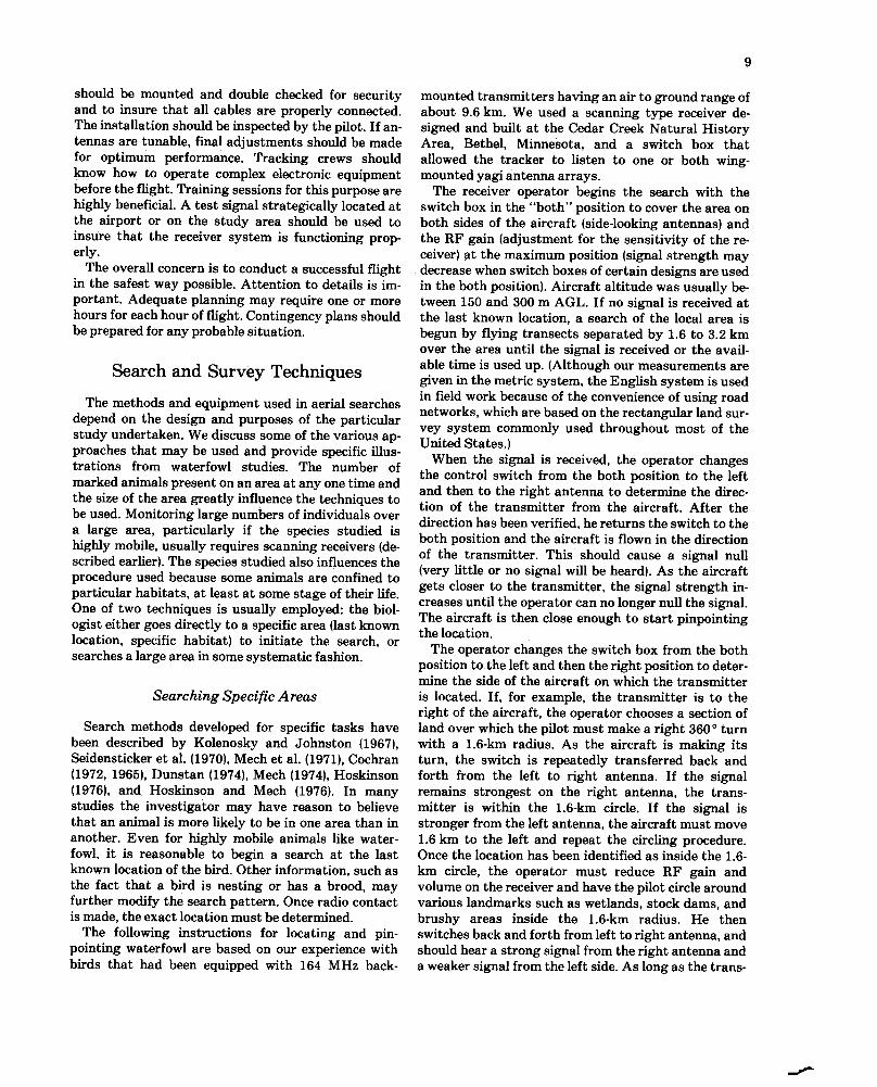
3600/SR X as, where NC = Number of channels pro-grammed; MD = Minimum parallel detection distance(miles, kilometers, or nautical miles; units of distanceand speed used for MD and as must be consistent);SR = Receiver scan rate (seconds/channel); andas = Maximum ground speed of aircraft (miles/hour.
kilometers/hour, or knots). Minimum parallel detectiondistance (MD) is measured parallel to the aircraftground track and within the transect through an areaover which the signal can be heard (Fig. 5). The shapeof this area is related to the antenna receiving patternsdiscussed in an earlier section (Figs. 3 and 4). Testflights should be conducted to determine the values ofsignal range and MD for specific transmitters and re-ceiving systems. Data obtained in tests flown to eval-uate waterfowl telemetry equipment in September1978 and April 1979 (Cessna 172, side-Iooking yagi an-tennas, 15° tilt) showed that anMD of 8.0 kmoccurredalong the aircraft ground track (Fig.5). Transectwidth for the example diagrammed in Fig. 5 was set at9.6 km; signal range was determined to be 4.8 km.These characteristics are specific for the equipment weused in the test and may not accurately reflect the per-formance of other systems. The approximate relationbetween MD (km) and signal range (km) is shown in the
Searches Over Large Areas
Some types of studies, especially those that requiremarking a large number of animals over a large area.frequently require different search techniques thanthose described above. These techniques may also berequired when the original contact cannot be made bythe specific area method because of the high mobilityof the marked animal. Wide area searches are usuallymade by flying a pattern of parallel flight transectsand using a scanning receiver. We have used the fol-lowing procedures to determine the most efficientsearch design. Width of the transect is determined bythe maximum signal range that can be reliably de-tected for the weakest transmitter of those to be usedin the field. Signal range is measured perpendicular tothe aircraft track and parallel to the ground. To deter-mine the number of animals that can be searched for ,the operator uses the equation NC = MD X
c
~
Q)ocas
0
O
c
.2
tiQ)
iC
~
""iU
~0.
E~
E
.c
~
/.
/
Signal Range, R
(mi)
Fig. 6. Relation between minimum parallel detection rangeand signal range.
equation: MD = 0.88 R -0.98, where R = signaldetection range (Fig. 6).
The minimum receiver scan rate that was effective inour tests was 2-sec dwell on each channel (pulse rate ofthe transmitters was about loo pulses/min). We esti-mated the maximum ground speed of the aircraft to be193 km/h. This gave us a calculated capability of moni-toring 75 channels. Another variable that determinesthe number of animals that can be handled in a search,but that is not in the above equation, is transmitterfrequency drift. This problem may require the investi-gator to program two or three channels with a spreadof frequencies around each transmitter in the searcharea. Experience with the transmitters and receivingsystem will help resolve this problem.
We found that this procedure formed a logical basisfor planning the search of a large area, but there areoften variables that have not been taken into account.Transmitters with excessively low range, greater thannormal drift, or in certain locations (e.g., under water ,in a den) can invalidate results from the basicequation. Results vary from day to day because ofatmospheric conditions or radio interference; differentobservers also differ in their ability to hear weaksignals and in their skill and experience in handling theequipment.
not located by radio signal was absent from the searcharea at the time of the search. Some measure of track-ing efficiency therefore becomes highly desirable, andmay be mandatory if the objectives of some studies areto be met. We have adopted and modified a mark-recapture technique first described by Hewitt (1967),who used it to estimate population density of breedingblackbirds. The method relied on an observation tomark a territory rather than the actual capture andmarking of the bird.
In our adaptation of the technique, two tracking air-craft were flown, one as close behind the other as wassafe and practical. If a radio-marked bird was heard bythe observer in the first aircraft, the bird was treatedas a marked individual. The observer in the second air-craft treated the signal from an animal heard by thefirst aircraft as a recapture and any other signalreceived as the capture of an unmarked individual.Data derived by this technique yield an estimate of thenumber of birds with functional transmitters presenton an area, as well as separate estimates of the track-ing efficiency of the two aircraft.
The vast literature describing mark recapturemethods and their underlying assumptions was sum-marized by Otis et al. (1978). In the discussion thatfollows, we use the same notation they used for thetwo models presented-Mh ("capture probabilitiesvary by individual animal") and Mo ("capture prob-abilities are constant"). Model Mh seems most appro-priate for the two-plane search. The model assumesthat each member of the population has its own prob-ability of capture, independent of all other members ofthe population. This assumption allows for trans-mitters of differing power and distance from the air-craft. The assumption of no difference between trap-ping occasions and no behavior response to trappingare also made. These assumptions may be met if thepasses of planes 1 and 2 are close together and there isno movement of animals between passes and the firstplane does not cause the animal to enter a den or someother area where the signal would be attenuated. Theobservers must also work independently of each other .In most applications of mark recapture methods, themarking of only a small portion of the population andthe relatively few recaptures cause imprecise esti-mates of population size. In the two-plane search, alarger portion of the population may be "marked" byplane 1 and "recaptured" by plane 2; therefore, moreprecise estimates of the population size of radio-marked animals can be obtained.
During field work in 1978 on a study of breedingmallards (Anas platyrhynchos) in North Dakota, weused the two-plane search in an area where intensivepreliminary tracking indicated the presence of 10radio-equipped ducks. In two search trials, populationestimates were 10.5 and 10.0. Efficiency of crews
Probability of Finding an Animal Present in theArea Searched
Because of the variables discussed above, the in-vestigator can seldom assume that an animal that was

12
12.9-km
-spacing-203
21.5
19.3-km spacing: trial--
~ 1-
167
19.5
2
179
21.5
6
206
23.0
Mt+l
11
N
Mo nln2m2N
20
17
17
20.1
14
11
9
17.4
1015
8
19.5
141813
19.7
101810
19.6
11
18
9
23.4
151813
20.9p..V(N)
0.92 0.72 0.64 0.81
~~- 0.15~ ~8Model Mh-probability of capture different; model Mo-probability of capture equal.
bModel Mh: t = number of trapping occasionsiin our study 2).
M t+ 1 = number of birds found I time by both planes.
II = number of birds found by both planes.
N = estimated number of radio-marked birds = M t+ 1 + 1j211.
ModelMo: nl = number of birds found by plane 1.
n2 = number of birds found by plane 2.
m2 = number of birds found by plane 2 that were also found by plane 1.
N = (nl + n2)2/4 m2.
p = estimated probability of finding a bird on a given flight = nl + n2/2f.I.
v(M = estimated variance of N = f.rr(I-p)-t -t(I-p)-1 + t-lJ-l.
0.71
3.14
0.62
8.50-
0.79
1.24
and operational experience. Knowledge of the speciesstudied may greatly enhance the effectiveness oftracking efforts.
Special Considera tions
Low-level OperationsIf the survey requires continuous flight below a
height of about 150 m AGL, additional details shouldbe considered. The pilot should be experienced in low-level work, and both pilot and observer should befamiliar with the area to be searched. Local F AAauthority, sheriffs office, refuge managers, and gamewardens should be notified of the approximate timeand area of the survey. Helmets, fire retardant cloth-ing, and boots should be worn during low-Ievel work.Specific agency regulations concerning this type ofwork should be reviewed. Federal Aviation Regu-lations, part 91.79, concerning minimum safe alti-tudes, specify that except for landing and takeoff anaircraft should be operated so that in the event of apower failure the aircraft can be landed without endan-gering persons on the ground. Over congested areas(cities, towns, or settlements) aircraft should remainabove an altitude of 300 m above the highest obstaclewithin a horizontal radius of 600 m of the aircraft. In
varied from 30 to 80%. Because the actual size of themarked population in 1978 was not known, we de-signed a simulated test of the method during spring1979. Twenty-one transmitters with an averageground to air range of about 9.6 km were placed atrandom in an area 16.1 X 35.4 km. A number of trialswith different observers were flown along transects 9.6and 12.9 km apart. At the 9.6-km spacing, all ob-servers found all radios. The same was true at 12.9 kmexcept for one trial (Table I). By taking every otherline, we simulated searches at 19.3-km spacing.
Although these results are preliminary, we believethat the two-plane search holds considerable promisefor estimating the number of radio-marked animals onan area and for estimating the proportion of animalspresent on an area that an air crew can be expected tolocate.
The tracking techniques described in this section arebased on our experience with specific types of equip-ment used for tracking radio-marked waterfowl.Although they should furnish guidance for the designof radiotelemetry studies, each new study requiresmodifications and additional techniques. Successfuluse of aerial methods requires a thorough under-standing of the capabilities of the system used, andthis knowledge must be gained through both testing
Modela
and
p!!:!ameter~~ --
Mh3 4 5
-~ -
19 18 20
6 8 11
22.0 22.0 25.5

3
other situations aircraft must remain at least 150 mAGL, except over water, where aircraft must remainat least 150 m from persons, vessels, or structures.Flight operations below 150 m may require FAAauthorization.
munication). Small amounts of ice on the elements maycause them to flutter. thereby setting up serious vibra-tions.
Fatigue and Motion Sickness
Helicopters Human fatigue is an important consideration whentracking operations are conducted from an aircraft.Two hours appear to be the limit that an individual caneffectively monitor receiving equipment and do a satis-factory job of data recording, navigation, and otherfunctions. Weather conditions playa large role: hightemperatures and turbulence further reduce a person'sability to concentrate on the job at hand. If turbulenceis severe, operations may have to be reduced or re-scheduled. Flights should generally be started as earlyin the morning as practicable to avoid turbulence andthunderstorms that often develop as the day pro-gresses.
Motion sickness may detract from the efficiency ofthe tracking operation. Although a few people sufferfrom chronic motion sickness, most can readily adaptto turbulent flying conditions. Certain motion sicknessdrugs are useful, but sometimes cause a temporaryloss of navigation or tracking skill. Observers shouldnot fly if they are suffering from an upset stomach.Many persons induce motion sickness by constantlyturning their head during steep turns and other un-usual attitudes. This situation commonly occurs whenoperators are photographing terrain objects. The headshould be turned as little as possible; it should be heldin a forward and upright position. It is better to movethe eyes rather than the head (Federal AviationAdministration 1974). Some other preventive meas-ures include opening air vents, loosening of clothing,and frequent visual reference to the distant horizon.Crew members in the back seat of the aircraft are sub-jected to increased gravity forces. The pilot should beinformed if crew members experience discomfort.
To a large degree the comfort of the aircraft crewdetermines the success of the flight. The interest of thepilot in the goals and objectives of the project is im-portant when the flying becomes repetitive and boring(see Hoskinson 1976). Patience and precision are oftenrequired to locate radio signals and data must be accu-rately and thoroughly recorded. Distractions to thecrew may introduce errors that are difficult or impos-sible to correct after the flight is co~pleted.
The helicopter has proved to be highly effectivebecause of its ability to travel at slow speeds, hover ,and land at almost any site. The high cost of operation,relatively short cruising radius, and the limited avail-ability of these aircraft prevent greater use in bio-telemetry work. Sometimes reduced rates on heli-copters can be obtained by contracting for a specifiedblock of time or by sharing contract expenses withother agencies in need of helicopter services. Cruisingradius (or on-station time) can be extended by the useof a pickup truck with a suitable fuel tank and transfersystem that can be used for refueling the helicopter atrendezvous points.
Our experience with a Jet Ranger in prairie terrainshowed that the most effective method for use of thisaircraft was to search for a signal from an altitude ofseveral hundred meters. When a signal was detectedthe helicopter was maneuvered downwind of the signalat an altitude of less than 15 m. Signal directionalitywas best determined when the helicopter, equippedwith a forward-looking antenna, moved slowly upwindtoward the signal, occasionally yawing left and right.This method provided precise locations of ducks onnests or in marshes, and we were often able to see birdsor to land and collect additional data at nest sites.Some animals flee from a low-flying helicopter, andothers attempt to hide. The tolerance of differentspecies under different situations must be determinedby experience.
When operating a helicopter in the vicinity ofnesting raptors caution should be exercised as thesebirds may attempt to stoop on a hovering or slow-moving helicopter. The pilot should attempt to maneu-ver the helicopter so that it is above any raptors flyingnearby.
Flight Characteristics and Jcing Conditions
Tracking antennas mounted on the wing strutscause increased drag on the aircraft and result in areduction of airspeed of about 5 to 7 knots in a Cessna172. This factor should be considered, particularlyduring low-altitude operations. A good airspeed safetymargin should be maintained and steep turns shouldbe avoided. If icing conditions are encountered, icemay tend to build up on antenna elements before itforms on flight surfaces (W. E. Berg, personal com-
Acknowledgments
We thank pilots J. Engman, J. Goldsberry, M.Holcomb, R. Jackson, M. Meier, J. Peterson, J. Schu.bert, H. Simonson, and J. Wehler for their help in con.ducting test and tracking flights; J. Gulke, J. Heg.

14
genes, R. Reichle, R. Schuster, J. Sease, and J. Win-ters for assistance in the collection of data; I. J. Ball,R. J. Greenwood, R. E. Kirby, A. L. Kolz, L. D. Mech,K- D. Norman, C. Smith, and K. J. Reinecke (all of theU.S. Fish and Wildlife Service); W. E. Berg (MinnesotaDepartment of Natural Resources); W. D. Garrett,J. W. Jutson, L. R. Langdon, and S. C. Peterson(Office of Aircraft Services, U .S. Department of the In-terior), and F. L. Kellogg (Federal Aviation Admin-istration, U.S. Department of Transportation) for pro-viding helpful suggestions during preparation of themanuscript; A. M. Frank and D. H. Johnson for pro-viding assistance in statistical analysis; R. Aurlandand R. Braaten for help in design and construction ofantenna mounts; and 0. D. Georgen and F. L. Kellogg(both of the F AA) for helpful suggestions for im-proving the design of the antenna mounts.
References
in north-central Minnesota. J. Wildl. Manage.41(3):345-359.
Graber, R. R. 1965. Night flight with a thrush. Aubudon67(6):368-374.
Hewitt, 0. H. 1967. A road-count index to breeding popu-lations of red-winged blackbirds. J. Wildl. Manage.31(1):39-47.
Hoskinson, R. L. 1976. The effect of different pilots on aerialtelemetry error. J. Wildl. Manage. 40(1):137-139.
Hoskinson, R. L., and L. D. Mech. 1976. White-tailed deermigration and its role in wolf predation. J. Wildl. Manage.40(3):429-441.
Judd, S. L., and R. R. Knight. 1977. Determination of grizzlybear movement patterns using biotelemetry .Pages 93-100in Proc. 1st Int. Conf. Wildl. Biotelemetry, July 27-29,1977. Laramie, Wyo.
Kirby, R. E., J. H. Riechmann, and M. E. Shough. 1976. Apreliminary report on Minnesota's innovative 1973 water-fowl season. Wildl. Soc. Bull. 4(21:55-63.
Kolenosky, G. B., and D. H. Johnston. 1967. Radio trackingtimber wolves in Ontario. Am. Zool. 7(2):289-303.
Mech, L. D. 1974. Current techniques in the study of elusivewilderness carnivores. Proc. Int. Congr .Game BioI.11:315-322.
Mech, L. D., L. D. Frenzel, Jr., and R. R. Ream. 1971. Move-ments, behavior, and ecology of timber wolves in north-eastern Minnesota. Pages 1-35 in L. D. Mech and L. D.Frenzel, eds. Ecological studies of timber wolf in north-eastern Minnesota. USDA Forest Service, North CentralForest Experiment Station Research Paper NC-52. 62 pp.
Otis, D. L., K. P. Burnham, G. C. White, and D. R. Anderson.1978. Statistical inference from capture data on closed ani-mal populations. Wildl. Monogr .62. 135 pp.
Ramo, S., and J. R. Whinnery. 1962. Fields and waves inmodern radio. John Wiley and Sons, New York. 576 pp.
Seidensticker, J. C., M. G. Hornocker, R. R. Knight, and S. L.Judd. 1970. Equipment and techniques for radio trackingmountain lions and elk. Idaho Coop. Wildl. Res. Unit, For.Wildl. Range Exp. Stn., Bull. 6. 20 pp.
Storm, G. L., R. L. Andrews, R. L. Phillips, R. A. Bishop,D. B. Siniff, and J. R. Tester. 1976. Morphology, reproduc-tion, dispersal and mortality of midwestern red fox popu-lations. Wildl. Monogr .49. 82 pp.
U.S. Department of the Army. 1958. Universal transversemercator grid. Technical Manual TM 5-241-8. U.S. Govern-ment Printing Office 1969-390-947/404.66 pp.
Weeks, R. W., F. M. Long, J. E. Lindsay, R. Bailey, D.Patula, and M. Green. 1977. Freshwater fish tracking byaircraft. Pages 63-69 in Proc. 1st. Int. Conf. Wildl. Bio-telemetry, July 27-29, 1977. Laramie, Wyo.
Whitehouse, S., and D. Steven. 1977. A technique for aerialradio tracking. J. Wildl. Manage. 41(4):771-775.
Winter, J. D., V. B. Kuechle, D. B. Siniff, and J. R. Tester.1978. Equipment and methods for radio tracking fresh-water fish. Agric. Exp. Stn. Univ. Minn. Misc. Rep. 152.18pp.
Amlaner, C. J., Jr. 1980. The design of antennas for use inradiotelemetry. Pages 251-261 in C. J. Amlaner, Jr., andD. W. MacDonald, eds. A handbook on biotelemetry andradio tracking. Pergamon Press, Oxford.
AVM Instrument Company. 1979. AVM radiotelemetryequipment and techniques manual. A VM Instrument Co.,Champaign, 111. 32 pp.
Cederlund, G., T. Dreyfert, and P. Lemnell. 1979. Radio-tracking techniques and the reliability of systems used forlarger birds and mammals. Rapport SNV PM 1136, Forsk-nings-station, Grimso, Sweden.
Cochran, W. W. 1965. Techniques in aerial telemetric studiesof nocturnal migration of birds. Progress Report 1, Na-tional Science Foundation GB-3155, December 8, 1965.
Cochran, W. W. 1972. Long-distance tracking of birds. Pages39-59 in S. R. Galler et al., eds. Animal orientation andnavigation. National Aeronautics and Space Administra-tion, Washington, D.C. NASA SP-262. 606 pp.
Cochran, W. W., G. G. Montgomery, and R. R. Graber. 1967.Migratory flights of Hylocichla thrushes in spring: A radio-telemetry study. The Living Bird 6:213-225.
Crissey, W. F. 1949. The airplane in fish and game work.Conserv .Dep., Albany. Fish Wildl. Inform. Bull. 4. 20 pp.
Dunstan, T. C. 1974. Location of a lost hawk by telemetryfrom an airplane. Hawk Chalk 13(3):38-42.
Federal Aviation Administration. 1974. Medical handbookfor pilots. U.S. Govt. Printing Office, Washington, D.C.74pp.
Gilmer, D. S., R. E. Kirby, I. J. Ball, and J. H. Riechmann.1977. Post-breeding activities of mallards and wood ducks
~~~

15
Appendix A
Construction of Antenna Mounts
The basic mount design we use to attach biotelem-etry antennas to aircraft was developed about 10 yearsago and was gradually improved through a series ofmodifications resulting in the designs described here.Other biologists have developed mounts that may beequally satisfactory. Illustrated in this appendix aredesigns for wing strut and helicopter mounts that wereapproved by local FAA authority. We emphasize that
A- 13/16" O.D. aluminum tubing
B- 1/16. flexible aluminum
C & D -17/16. O.D. aluminum tubing
E,F,G,H,I,J,K & L- 1/8. aluminum plate
M -all bolts 5/16.
N -heliarc welds symbolized by -
~ 6 112. '---11518. cI::::.1
~I4.
~
0N
~~~. ~
J~6.;~
A- bracket shaft K
=
FL
f f
36.
Fig. A.l. Schematic diagram of airplane wing strut yagi antenna mount. Measurements are provided in English units. Insideof cuff lined with padding to avoid scratching strut surface. All nuts and bolts should be certified for use on aircraft. Theseare available at any airport with repair facilities. Use lock nuts on cuff.
approval of these antenna mounts for our work doesnot insure that similar designs will be approved inother situations. Approval authority rests solely withthe F AA inspector who is guided by his own judgmentand current official directives and regulations.
We present the following diagrams so that otherbiologists will have adequate information to constructsimilar mounts or use this information as a basis to de-velop other designs (Figs. A-l, A-2).

16
17
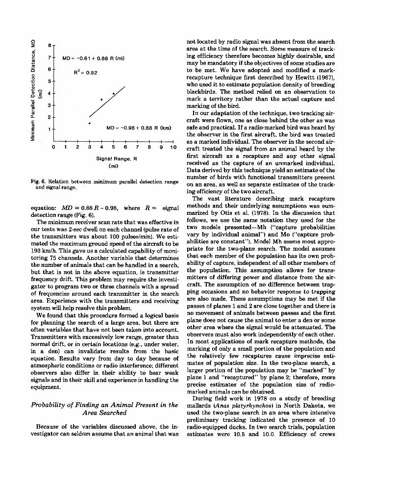
Appendix B
Antenna Test Procedures Free space corrections were used. Although strictlyspeaking these equations are valid only between an-tennas in space, air to ground transmissions closelyapproximate these conditions, especially at lower fre-quencies where atmospheric attenuation is low.
The actual power received at the antenna (Pr) isequal to:
PT-PL +AG
where Pr = received power in decibels (db);PT = transmitted power (db); and PL = path loss = 20(log aircraft to receiver antenna distance/distance fromaircraft to receiver antenna at its closest point).
AG = Antenna gain (db)db = 10logP1/P2whereP1/P2isapowerratio.
Rearrangement of terms yields the following equation:
AG=Pr+PL-PT
Because P r and PT are held constant and PL can becalculated, the antenna gain is a constant. Since theangle to the aircraft is also known, the antenna patterncan be determined.
Tests were conducted near Jamestown, NorthDakota, and Cambridge, Minnesota. The test areaswere chosen because they had a good network of inter-secting roads, which allowed easy and accurate deter-mination of aircraft position (road intersections were
GROUND STATION EQUIPMENT
~ ~I TRANSMITTER ~ ...I ~n ~..
" ~ LEI
AIRCRAFT EQUIPMENT
The reversal of the transmitter and receiving an-tennas is always valid because the reciprocity theoremstates that in linear systems the antenna pattern forreception is identical with that for transmission (Ramoand Whinnery 1962:558).
The transmitter located in the aircraft was crystalcontrolled, battery powered, and regulated to keep theoutput constant. Either of two antennas were selectedby switching the antenna cables at the transmitter .
The signal was received by a quarter-wave groundplane antenna located on the ground and was fed into areceiver through a calibrated attenuator (Fig. B-l).The signal output level was displayed on an oscillo-scope and voltage meter. The signal frequency wasmonitored with a frequency meter, and drift wascompensated by using the receiver's fine-tune control.Tests indicated that the signal frequency could vary::!:500 Hz before the signal level changed more than::!:1 db. The calibrated attenuator was used to main-tain the output at a constant level. Using this tech-nique, one can easily maintain calibration and elimi-nate nonlinearities in the system. Tests were not con-ducted on a specially designed antenna range. Manyvariables affect the results and may prevent the exactduplication of our findings.
A signal from a calibrated signal generator wasswitched to set the reference gain level of the systemat the start and completion of each run. Although littlegain adjustment was needed the receiver was adjustedto keep the output constant for a given input signallevel.
To make comparisons between different altitudesand antenna configurations for each aircraft, wenormalized all measurements to the maximum valuefor that aircraft. No comparisons were made betweenantenna gains on different aircraft because the gainvariation would probably be masked by variation intransmission conditions and because we had no way toinsure the calibration of the system between aircraft.The comparison between antenna patterns on differentaircraft is valid because the comparison is a relativeone. The shape of the gain pattern is not dependent onthe signal amplitude at the antenna.
A distance correction was made to compensate forthe loss in signal level due to the changing distancesthe signal had to travel as the aircraft moved towardand away from the receiver site.
Fig. 8-1. Equipment used to obtain electronic measurementsduring tests of antennas mounted on aircraft.
18
used as reference points). Intersections occurred ateach O.8-km interval at Jamestown and at 1.6-kmintervals at Cambridge. The distance from the re-ceiving site to the flight path was 3.2 km at James-town and 3.5 km at Cambridge. As the aircraft flewalong the test transect it reported its position by two-way radio each time it crossed a road intersection. Thereceiving station then recorded the correspondingattenuation level for that point. For all except loop an-tennas, two runs were made for each configuration andaltitude tested. The readings were then corrected fordistance (path loss), normalized to a-reference level,and plotted. The curves drawn were for the best fit tothe data points.
Problems were encountered with vertical wind gra-dients, which caused variation in altitudes; theaverage of two runs decreased this error. Also, thepattern is not highly dependent on altitude. We wouldexpect the error caused by the estimated ::!: 30-m varia-tion in altitude we encountered to be small. Errors dueto crosswinds are a greater problem because theycause the aircraft to "crab" and therefore have a directeffect on the pattern. The only compensation we hadfor crosswinds was to average runs from oppositedirections. Although errors attributable to crosswindsare difficult to measure, we do not believe the cross-wind effects have significant influence on the antennapatterns.

19
Appendix c
Equipment Checklist electrical tapeextra bolts, nuts, washersmultimeter"Restricted Category" signs (if required)
Procedural Checklist
List of animals to be located during flight (also noteson frequency drift)
Map of last known animal locations (also considerrecent movement patterns if known)
Blank maps and data formsClipboardPencils, pensCamera and film (if desired)Communication radio (air to ground)Test signal transmittersTimepiece to calibrate aircraft clockOperational receiverBackup receiverAuxiliary power suppliesHeadphonesSwitch boxesExtra coaxial cable (proper length and connectors)Antennas and mounts, with coaxial cable attachedPadding for mountsTool kit for mounting antennas:
adjustable wrenchesscrewdriverslip-joint pliers
Attach mount with antennas to aircraft (adjust asnecessary)
Run coaxial cables into cabinHook up switch boxes and receiverTest system: make sure switch box is functioning
correctlyReview flight plan with pilotPilot recheck antenna mountsTune antenna (as necessary)Check receiver battery voltageScanning receiver:
check programmed frequenciescheck dwell timecheck appropriate mode switches
Place .'Restricted Category" signs near cabin door (ifrequired)


![Theinuenceofdynamicenvironmental ... · Klinardet al. Anim Biotelemetry Page3of17 studiesreportedasignicantpositiverelationship[23], signicantnegativerelationship[25],andnosignicant](https://img.pdfslide.us/doc/110x75/6062d3607be474540d440769/theinuenceofdynamicenvironmental-klinardet-al-anim-biotelemetry-page3of17-studiesreportedasignicantpositiverelationship23.jpg)


![In vivo micro medical devices [Recovered]tam.northwestern.edu/summerinstitute/_links/_courses/2007... · • 1967, Ko, W. H and NeumanMR, “Implant Biotelemetry and Microelectronics”Science](https://img.pdfslide.us/doc/110x75/5c07470509d3f2922c8b5bdd/in-vivo-micro-medical-devices-recoveredtam-1967-ko-w-h-and-neumanmr.jpg)


![Haast roar blocks overview map 2 - Department of Conservation · 2] Wilderness area - no aircraft landings Department Of Conservation Te Papa Atawha.i newzealand.govt.nz pmest Km](https://img.pdfslide.us/doc/110x75/6047185838dbb8672978598f/haast-roar-blocks-overview-map-2-department-of-conservation-2-wilderness-area.jpg)