Embed Size (px)
Citation preview
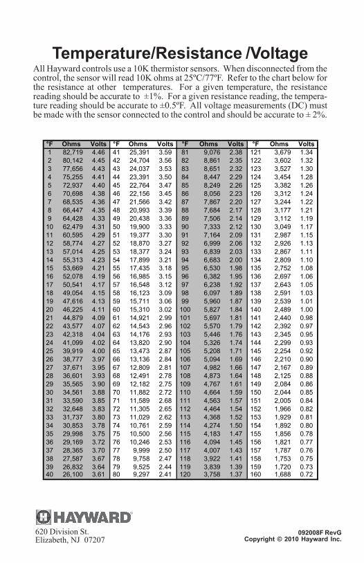
Temperature/Resistance /VoltageAll Hayward controls use a 10K thermistor sensors. When disconnected from thecontrol, the sensor will read 10K ohms at 25ºC/77ºF. Refer to the chart below forthe resistance at other temperatures. For a given temperature, the resistancereading should be accurate to ±1%. For a given resistance reading, the tempera-ture reading should be accurate to ±0.5ºF. All voltage measurements (DC) mustbe made with the sensor connected to the control and should be accurate to ± 2%.
°F Ohms Volts °F Ohms Volts °F Ohms Volts °F Ohms Volts1 82,719 4.46 41 25,391 3.59 81 9,076 2.38 121 3,679 1.342 80,142 4.45 42 24,704 3.56 82 8,861 2.35 122 3,602 1.323 77,656 4.43 43 24,037 3.53 83 8,651 2.32 123 3,527 1.304 75,255 4.41 44 23,391 3.50 84 8,447 2.29 124 3,454 1.285 72,937 4.40 45 22,764 3.47 85 8,249 2.26 125 3,382 1.266 70,698 4.38 46 22,156 3.45 86 8,056 2.23 126 3,312 1.247 68,535 4.36 47 21,566 3.42 87 7,867 2.20 127 3,244 1.228 66,447 4.35 48 20,993 3.39 88 7,684 2.17 128 3,177 1.219 64,428 4.33 49 20,438 3.36 89 7,506 2.14 129 3,112 1.19
10 62,479 4.31 50 19,900 3.33 90 7,333 2.12 130 3,049 1.1711 60,595 4.29 51 19,377 3.30 91 7,164 2.09 131 2,987 1.1512 58,774 4.27 52 18,870 3.27 92 6,999 2.06 132 2,926 1.1313 57,014 4.25 53 18,377 3.24 93 6,839 2.03 133 2,867 1.1114 55,313 4.23 54 17,899 3.21 94 6,683 2.00 134 2,809 1.1015 53,669 4.21 55 17,435 3.18 95 6,530 1.98 135 2,752 1.0816 52,078 4.19 56 16,985 3.15 96 6,382 1.95 136 2,697 1.0617 50,541 4.17 57 16,548 3.12 97 6,238 1.92 137 2,643 1.0518 49,054 4.15 58 16,123 3.09 98 6,097 1.89 138 2,591 1.0319 47,616 4.13 59 15,711 3.06 99 5,960 1.87 139 2,539 1.0120 46,225 4.11 60 15,310 3.02 100 5,827 1.84 140 2,489 1.0021 44,879 4.09 61 14,921 2.99 101 5,697 1.81 141 2,440 0.9822 43,577 4.07 62 14,543 2.96 102 5,570 1.79 142 2,392 0.9723 42,318 4.04 63 14,176 2.93 103 5,446 1.76 143 2,345 0.9524 41,099 4.02 64 13,820 2.90 104 5,326 1.74 144 2,299 0.9325 39,919 4.00 65 13,473 2.87 105 5,208 1.71 145 2,254 0.9226 38,777 3.97 66 13,136 2.84 106 5,094 1.69 146 2,210 0.9027 37,671 3.95 67 12,809 2.81 107 4,982 1.66 147 2,167 0.8928 36,601 3.93 68 12,491 2.78 108 4,873 1.64 148 2,125 0.8829 35,565 3.90 69 12,182 2.75 109 4,767 1.61 149 2,084 0.8630 34,561 3.88 70 11,882 2.72 110 4,664 1.59 150 2,044 0.8531 33,590 3.85 71 11,589 2.68 111 4,563 1.57 151 2,005 0.8432 32,648 3.83 72 11,305 2.65 112 4,464 1.54 152 1,966 0.8233 31,737 3.80 73 11,029 2.62 113 4,368 1.52 153 1,929 0.8134 30,853 3.78 74 10,761 2.59 114 4,274 1.50 154 1,892 0.8035 29,998 3.75 75 10,500 2.56 115 4,183 1.47 155 1,856 0.7836 29,169 3.72 76 10,246 2.53 116 4,094 1.45 156 1,821 0.7737 28,365 3.70 77 9,999 2.50 117 4,007 1.43 157 1,787 0.7638 27,587 3.67 78 9,758 2.47 118 3,922 1.41 158 1,753 0.7539 26,832 3.64 79 9,525 2.44 119 3,839 1.39 159 1,720 0.7340 26,100 3.61 80 9,297 2.41 120 3,758 1.37 160 1,688 0.72
Electronic Solar Control Center
Operation and InstallationManualAQ-SOL-LV
AQ-SOL-LV-TCAQ-SOL-LV-SP
092008F RevGCopyright © 2010 Hayward Inc. www.haywardnet.com620 Division St.
Elizabeth, NJ 07207
Aqua Solar

12
IMPORTANT SAFETY INSTRUCTIONSWhen using this electrical equipment, basic safety precautions should always befollowed, including the following:
• READ AND FOLLOW ALL INSTRUCTIONS
• Disconnect all AC power during installation.
• Warning – To reduce the risk of injury do not permit children to use thisproduct unless they are closely supervised at all times.
• A green colored terminal marked “EARTH” is located inside the wiringcompartment. To reduce the risk of electrical shock, this terminal must beconnected to the grounding means provided in the electrical supplyservice panel with a continuous copper wire equivalent in size to thecircuit conductors supplying the equipment.
• All field installed metal components such as rails, ladders, drains, or othersimilar hardware within 3 meters of the pool, spa or hot tub shall bebonded to the equipment grounding bus with copper conductors notsmaller than 8 AWG US/ 6 AWG Canada.
SAVE THESE INSTRUCTIONS
5-Year Limited Solar WarrantyThis Five Year Limited Warranty statement is only applicable to Solar controls and accessoriessold and installed within the USA and Canada* and supersedes any warranty statements datedprior to November 1, 2010.
Hayward warrants its Hayward solar products to be free from defects in material or workmanship,under normal use and service for 5 years from date of manufacture, providing it is installedaccording to the installation instructions and specifications. The datecode stamped on theoutside of the product and also coded on the printed circuit board will be the sole determinationof manufacturing date.
To obtain warranty service or repair, please contact the place of purchase or the nearest Haywardauthorized warranty service center. For more information, please contact the HaywardTechnical Service Support Center or visit us on the web at www.haywardnet.com. Hayward willnot assume any of the cost incurred in removal or reinstallation of the product. One year outsidethe USA and Canada.
The express warranty above constitutes the entire warranty of Hayward Pool Products withrespect to its solar products and IS IN LIEU OF ALL OTHER WARRANTIES, EXPRESSEDOR IMPLIED, INCLUDING A WARRANTY OF FITNESS FOR A PARTICULAR PURPOSE.IN NO EVENT SHALL HAYWARD BE RESPONSIBLE OR ANY CONSEQUENTIAL ORINCIDENTAL DAMAGES OF ANY NATURE WHATSOEVER.
No wholesaler, agent, dealer, contractor, or other person is authorized to give any warranty onbehalf of Hayward. This warranty is void if the product has been altered in any way after leavingthe factory.
ChargesYears 1-3:no chargeYears 4-5 60% of current list price plus $5.00 shipping and handling
Unless a copy of the original purchase invoice is enclosed, the manufacturing datecode on theproduct will be used to determine the repair charges. Hayward reserves the right to charge anominal fee to cover inspection, test, and return freight for all controls where no faults orproblems are detected. All charges will be COD (COD charge will be included) unless you alreadyhave an open account in good standing with Hayward. If the product returned can not berepaired, Hayward will offer and equivalent credit towards the purchase of any new Haywardproduct. Products that exhibit evidence of abuse, misuse, field damage (water/fire damage, linevoltage applied to low voltage terminals, missing parts, etc.) or installed for more than thewarranty period are not eligible for warranty repair replacement.
11
On continuously indicates a probable open circuit in the "POOL" sensor or wiring.Flashing indicates a probable short circuit in the "POOL" sensor or wiring. In eithercase digital pool temperature display will show as "PErr". The solar heating andcooling functions will remain off until this problem is fixed, however, the recirculatefreeze protection (if enabled by the jumper) will still operate properly. Use the chart onthe back cover to check the "POOL" sensor with a voltmeter (you don't need todisconnect the sensor). Alternatively, you can disconnect the sensor and measurethe sensor resistance. Replace the sensor or fix the wiring as required. If the sensorand wiring are both good, then the main circuit PCB may have a problem.
7. "Solar Sensor" LED on or flashing "Err" on the solar temperature display:On continuously indicates a probable open circuit in the "SOLAR" sensor or wiring.Flashing indicates a probable short circuit in the "SOLAR" sensor or wiring. In eithercase digital pool temperature display for the "SOLAR" sensor will show as "CErr".The solar heating and cooling functions will remain off until this problem is fixed,however, the recirculate freeze protection (if enabled by the jumper) will still operateproperly.
Use the chart on the back cover to check the "SOLAR" sensor with a voltmeter (youdon't need to disconnect the sensor). Alternatively, you can disconnect the sensor andmeasure the sensor resistance. Replace the sensor or fix the wiring as required. If thesensor and wiring are both good, then the main circuit PCB may have a problem.
8. "Aux Sensor" LED flashing "Err" on the Aux temperature display:Flashing indicates a probable short circuit in the "AUX" sensor or wiring. The digitalpool temperature display for the "AUX" sensor will show as "AErr". This errorindication only occurs when the "AUX" sensor is being used for recirculate freezeprotection. When the Aux sensor is shorted, the Aqua Solar will use the "SOLAR"sensor as a backup freeze sensor and turn the recirculate freeze protection on whenthe temperature is less than 60ºF.
Use the chart on the back cover to check the "AUX" sensor with a voltmeter (youdon't need to disconnect the sensor). Alternatively, you can disconnect the sensor andmeasure the sensor resistance. Replace the sensor or fix the wiring as required. If thesensor and wiring are both good, then the main circuit PCB may have a problem.
Table of Contents
SPECIFICATIONSSPECIFICATIONSSPECIFICATIONSSPECIFICATIONSSPECIFICATIONSSpecifications Specifications Specifications Specifications Specifications ......................................................................1
OPERATIONOPERATIONOPERATIONOPERATIONOPERATIONControls Controls Controls Controls Controls ...............................................................................2
Temperature Display Temperature Display Temperature Display Temperature Display Temperature Display ........................................................3
INSTALLATIONINSTALLATIONINSTALLATIONINSTALLATIONINSTALLATIONMounting Mounting Mounting Mounting Mounting ..............................................................................4
Wiring Wiring Wiring Wiring Wiring ..................................................................................4
Jumper Settings Jumper Settings Jumper Settings Jumper Settings Jumper Settings ..................................................................9
TROUBLESHOOTINGTROUBLESHOOTINGTROUBLESHOOTINGTROUBLESHOOTINGTROUBLESHOOTINGTroubleshooting Troubleshooting Troubleshooting Troubleshooting Troubleshooting ...............................................................10
WARRANTYWARRANTYWARRANTYWARRANTYWARRANTYWarrantyWarrantyWarrantyWarrantyWarranty.............................................................................12
101
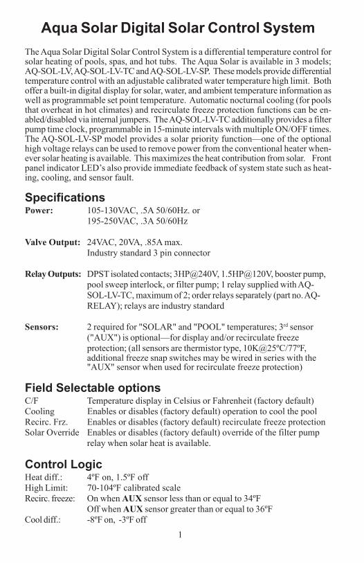
Aqua Solar Digital Solar Control SystemThe Aqua Solar Digital Solar Control System is a differential temperature control forsolar heating of pools, spas, and hot tubs. The Aqua Solar is available in 3 models;AQ-SOL-LV, AQ-SOL-LV-TC and AQ-SOL-LV-SP. These models provide differentialtemperature control with an adjustable calibrated water temperature high limit. Bothoffer a built-in digital display for solar, water, and ambient temperature information aswell as programmable set point temperature. Automatic nocturnal cooling (for poolsthat overheat in hot climates) and recirculate freeze protection functions can be en-abled/disabled via internal jumpers. The AQ-SOL-LV-TC additionally provides a filterpump time clock, programmable in 15-minute intervals with multiple ON/OFF times.The AQ-SOL-LV-SP model provides a solar priority function—one of the optionalhigh voltage relays can be used to remove power from the conventional heater when-ever solar heating is available. This maximizes the heat contribution from solar. Frontpanel indicator LED’s also provide immediate feedback of system state such as heat-ing, cooling, and sensor fault.
SpecificationsPower: 105-130VAC, .5A 50/60Hz. or
195-250VAC, .3A 50/60Hz
Valve Output: 24VAC, 20VA, .85A max.Industry standard 3 pin connector
Relay Outputs: DPST isolated contacts; 3HP@240V, 1.5HP@120V, booster pump,pool sweep interlock, or filter pump; 1 relay supplied with AQ-SOL-LV-TC, maximum of 2; order relays separately (part no. AQ-RELAY); relays are industry standard
Sensors: 2 required for "SOLAR" and "POOL" temperatures; 3rd sensor("AUX") is optional—for display and/or recirculate freezeprotection; (all sensors are thermistor type, 10K@25ºC/77ºF,additional freeze snap switches may be wired in series with the"AUX" sensor when used for recirculate freeze protection)
Field Selectable optionsC/F Temperature display in Celsius or Fahrenheit (factory default)Cooling Enables or disables (factory default) operation to cool the poolRecirc. Frz. Enables or disables (factory default) recirculate freeze protectionSolar Override Enables or disables (factory default) override of the filter pump
relay when solar heat is available.
Control LogicHeat diff.: 4ºF on, 1.5ºF offHigh Limit: 70-104ºF calibrated scaleRecirc. freeze: On when AUX sensor less than or equal to 34ºF
Off when AUX sensor greater than or equal to 36ºFCool diff.: -8ºF on, -3ºF off
Troubleshooting1. "Power" LED off:Check main power circuit breakers. Check to see if the Aqua Solar power is connectedto the LOAD side of the filter pump timer, in which case the Aqua Solar will only be onwhen the filter pump is on. Lastly, check the internal fuse which is located on the rightupper side of the main circuit board. If necessary, replace the fuse with a type 3AG, 2amp, slo-blo fuse, which is available in most electrical or electronics stores.
2. "Heating" LED is always on:Check that the switch is in the “AUTO” position. Check the sensor temperatures:The "Heating" LED should go off if the pool temperature is less than the "DesiredTemperature" OR if the solar temperature is less than the pool temperature. If thesensors appear to giving incorrect readings, check the sensors using the temperature/resistance/voltage chart on the back cover.
3. "Heating" LED never comes on:Verify that the switch is in the “AUTO” position. Check the sensor temperatures: The"Heating" LED should turn on when the pool temperature is less than the "DesiredTemperature" AND the solar temperature is warmer than the pool temperature. Theexception is when solar override is being used (typically when the pool is filtered atnight, but the solar override function is used to turn the filter pump on during the daywhen solar heat is available): In this case, there is a 2 hour minimum off time to preventrapid on/off cycling of the filter pump. If the sensors appear to giving incorrectreadings, check the sensors using the temperature/resistance/voltage chart on theback cover.
4. "Heating" and "Cooling" LEDs on simultaneouslyThis indicates that the main switch is in the "ON" position. The Aqua Solar willoperate the solar valve and the booster pump (if installed) regardless of the sensortemperatures. Set the switch back to "AUTO" to resume normal operation.
5. "Heating" and "Cooling" LEDs flashing simultaneouslyThis indicates that recirculate freeze protection is active (solar valve on, boost pumpon (if used), and filter pump on) due to the "AUX" sensor being less than 35ºF OR the"AUX" sensor being disconnected OR any freeze snap switches wired in series withthe "AUX" sensor being open. If the "AUX" sensor is not connected OR a freezesnap switch is open, the "AUX" temperature display will be " LO ". The Aqua Solarwill continue this operating mode until the "AUX" sensor rises above 35ºF AND allfreeze snap switches wired in series with the "AUX" sensor are closed. This functionoperates regardless of the position of the "ON / AUTO / OFF" switch.
6. "Pool Sensor" LED on or flashing "Err" on the pool temperature display:
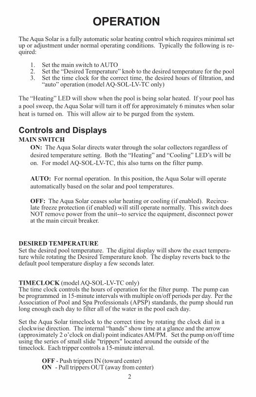
OPERATIONThe Aqua Solar is a fully automatic solar heating control which requires minimal setup or adjustment under normal operating conditions. Typically the following is re-quired:
1. Set the main switch to AUTO2. Set the “Desired Temperature” knob to the desired temperature for the pool3. Set the time clock for the correct time, the desired hours of filtration, and
“auto” operation (model AQ-SOL-LV-TC only)
The “Heating” LED will show when the pool is being solar heated. If your pool hasa pool sweep, the Aqua Solar will turn it off for approximately 6 minutes when solarheat is turned on. This will allow air to be purged from the system.
Controls and DisplaysMAIN SWITCH
ON: The Aqua Solar directs water through the solar collectors regardless ofdesired temperature setting. Both the “Heating” and “Cooling” LED’s will beon. For model AQ-SOL-LV-TC, this also turns on the filter pump.
AUTO: For normal operation. In this position, the Aqua Solar will operateautomatically based on the solar and pool temperatures.
OFF: The Aqua Solar ceases solar heating or cooling (if enabled). Recircu-late freeze protection (if enabled) will still operate normally. This switch doesNOT remove power from the unit--to service the equipment, disconnect powerat the main circuit breaker.
DESIRED TEMPERATURESet the desired pool temperature. The digital display will show the exact tempera-ture while rotating the Desired Temperature knob. The display reverts back to thedefault pool temperature display a few seconds later.
TIMECLOCK (model AQ-SOL-LV-TC only)The time clock controls the hours of operation for the filter pump. The pump canbe programmed in 15-minute intervals with multiple on/off periods per day. Per theAssociation of Pool and Spa Professionals (APSP) standards, the pump should runlong enough each day to filter all of the water in the pool each day.
Set the Aqua Solar timeclock to the correct time by rotating the clock dial in aclockwise direction. The internal “hands” show time at a glance and the arrow(approximately 2 o’clock on dial) point indicates AM/PM. Set the pump on/off timeusing the series of small slide "trippers" located around the outside of thetimeclock. Each tripper controls a 15-minute interval.
OFF - Push trippers IN (toward center)ON - Pull trippers OUT (away from center)
29
Jumper SettingsThe jumpers that enable/disable optional control features are located on the right sideof the main circuit board (see page 4). The factory default for all functions is "dis-abled" (each jumper will be on a single pin). To "enable" a function, simply take thedesignated jumper and place it over both pins.
COOLING: A high voltage relay for filter pump control is usually required to imple-ment this function. If Cooling is enabled, the Aqua Solar will cool the pool by turningon the filter pump and diverting the flow through the collector array whenever the"POOL" temperature is WARMER than the “Desired Temperature” setting AND the"SOLAR" sensor is COOLER than the pool water.
RECIRCULATE FREEZE PROTECTION: A high voltage relay connected tothe "FILTER PUMP" output and the AUX temperature sensor are required to imple-ment this function. If enabled, the Aqua Solar will turn the filter pump on and operatethe solar diverter valve whenever freezing conditions are detected (AUX sensor be-low 35ºF). See diagram on page 6 for typical relay wiring. When recirculate freezeprotection is enabled and the Aqua Solar senses a freeze condition at the AUX sensor,it will circulate the pool water continuously through the entire filtration plumbingloop including the solar collector panels. While this type of freeze protection isusually adequate in relatively mild climates, it is extremely important that the AUXsensor be properly placed and that the homeowner realize that the system is unpro-tected in the event of a power failure. Hayward highly recommends that one or more“freeze snap switches” (model GC-3) be placed in areas with susceptible plumbing(example: areas that may be shaded, or get more wind exposure) and that these sen-sors be wired in series with the AUX sensor. Recirculate freeze protection is NOTrecommended in climates where freezing temperatures are common or last forextended periods.
WARNING--If recirculate freeze protection is NOT selected, then you are rely-ing on the collectors naturally draining to provide freeze protection. It is veryimportant that you use a non-positive seal valve or drill a hole in the diverter ofa positive seal valve to allow the collectors to drain. This will NOT work if thecollectors are located below the water level of the pool.
CELSIUS DISPLAY: This will change the temperature display to degrees--Celsius.The factory default is degrees--Fahrenheit.
SOLAR OVERRIDE: A high voltage relay connected to the "FILTER PUMP" outputis required to implement this function. When "Solar Override" is enabled, the AquaSolar will override the filter pump timeclock (external timeclock for AQ-SOL-LV orinternal timeclock for AQ-SOL-LV-TC) and turn the filter pump on whenever there is acall for solar heating or cooling. During periods of on/off cloudy days this may resultin the pump turning on and off multiple times. It is also possible that the pump couldturn on during hot night conditions. To prevent rapid on/off cycling of the filter pumpduring cloudy conditions, the pump will also remain on for a minimum of 10 minutes,and will remain off for a minimum of 2 hours.
83
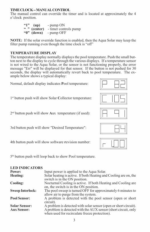
TIME CLOCK -- MANUAL CONTROLThe manual control can override the timer and is located at approximately the 4o’clock position.
“1” (up) - pump ON“ ” (center) - timer controls pump“0” (down) - pump OFF
NOTE: If the solar override function is enabled, then the Aqua Solar may keep thefilter pump running even though the time clock is “off”
TEMPERATURE DISPLAYThe temperature display normally displays the pool temperature. Push the small but-ton next to the display to cycle through the various displays. If a temperature sensoris not wired to the Aqua Solar, or the sensor is not functioning properly, the errormessage "Err" will be displayed for that sensor. If the button is not pushed for 30seconds, the display will automatically revert back to pool temperature. The ex-ample below shows a typical display:
Normal, default display indicates Pool temperature:
1st button push will show Solar Collector temperature:
2nd button push will show Aux temperature (if used):
3rd button push will show "Desired Temperature":
4th button push will show software revision number:
5th button push will loop back to show Pool temperature.
LED INDICATORSPower: Input power is applied to the Aqua Solar.Heating: Solar heating is active. If both Heating and Cooling are on, the
switch is in the ON position.Cooling: Nocturnal Cooling is active. If both Heating and Cooling are
on, the switch is in the ON position.Sweep Interlock: The pool sweep is turned OFF for approximately 6 minutes to
allow air to purge from the system.Pool Sensor: A problem is detected with the pool sensor (open or short
circuit).Solar Sensor: A problem is detected with solar sensor (open or short circuit).Aux Sensor: A problem is detected with the AUX sensor (short circuit, only
when used for recirculate freeze protection).
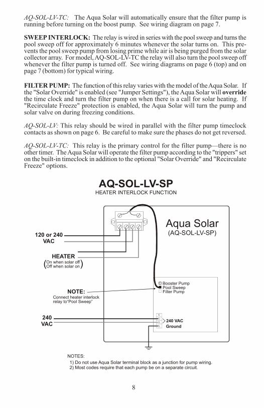
AQ-SOL-LV-TC: The Aqua Solar will automatically ensure that the filter pump isrunning before turning on the boost pump. See wiring diagram on page 7.
SWEEP INTERLOCK: The relay is wired in series with the pool sweep and turns thepool sweep off for approximately 6 minutes whenever the solar turns on. This pre-vents the pool sweep pump from losing prime while air is being purged from the solarcollector array. For model, AQ-SOL-LV-TC the relay will also turn the pool sweep offwhenever the filter pump is turned off. See wiring diagrams on page 6 (top) and onpage 7 (bottom) for typical wiring.
FILTER PUMP: The function of this relay varies with the model of the Aqua Solar. Ifthe "Solar Override" is enabled (see "Jumper Settings"), the Aqua Solar will overridethe time clock and turn the filter pump on when there is a call for solar heating. If"Recirculate Freeze" protection is enabled, the Aqua Solar will turn the pump andsolar valve on during freezing conditions.
AQ-SOL-LV: This relay should be wired in parallel with the filter pump timeclockcontacts as shown on page 6. Be careful to make sure the phases do not get reversed.
AQ-SOL-LV-TC: This relay is the primary control for the filter pump—there is noother timer. The Aqua Solar will operate the filter pump according to the "trippers" seton the built-in timeclock in addition to the optional "Solar Override" and "RecirculateFreeze" options.
Booster PumpPool SweepFilter Pump
120 or 240VAC
240VAC
Aqua Solar(AQ-SOL-LV-SP)
AQ-SOL-LV-SPHEATER INTERLOCK FUNCTION
NOTES:1) Do not use Aqua Solar terminal block as a junction for pump wiring.2) Most codes require that each pump be on a separate circuit.
Ground240 VAC
On when solar offOff when solar on( )
HEATER
NOTE:Connect heater interlockrelay to“Pool Sweep”
4
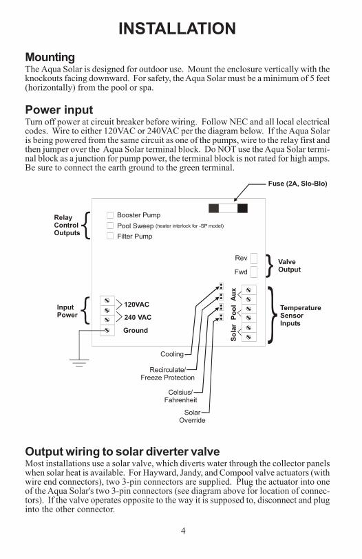
INSTALLATIONMountingThe Aqua Solar is designed for outdoor use. Mount the enclosure vertically with theknockouts facing downward. For safety, the Aqua Solar must be a minimum of 5 feet(horizontally) from the pool or spa.
Power inputTurn off power at circuit breaker before wiring. Follow NEC and all local electricalcodes. Wire to either 120VAC or 240VAC per the diagram below. If the Aqua Solaris being powered from the same circuit as one of the pumps, wire to the relay first andthen jumper over the Aqua Solar terminal block. Do NOT use the Aqua Solar termi-nal block as a junction for pump power, the terminal block is not rated for high amps.Be sure to connect the earth ground to the green terminal.
Output wiring to solar diverter valveMost installations use a solar valve, which diverts water through the collector panelswhen solar heat is available. For Hayward, Jandy, and Compool valve actuators (withwire end connectors), two 3-pin connectors are supplied. Plug the actuator into oneof the Aqua Solar's two 3-pin connectors (see diagram above for location of connec-tors). If the valve operates opposite to the way it is supposed to, disconnect and pluginto the other connector.
7
Booster PumpPool SweepFilter Pump240
VAC
240VAC
FilterPump
Solar BoosterPump
Aqua Solar(AQ-SOL-LV-TC)
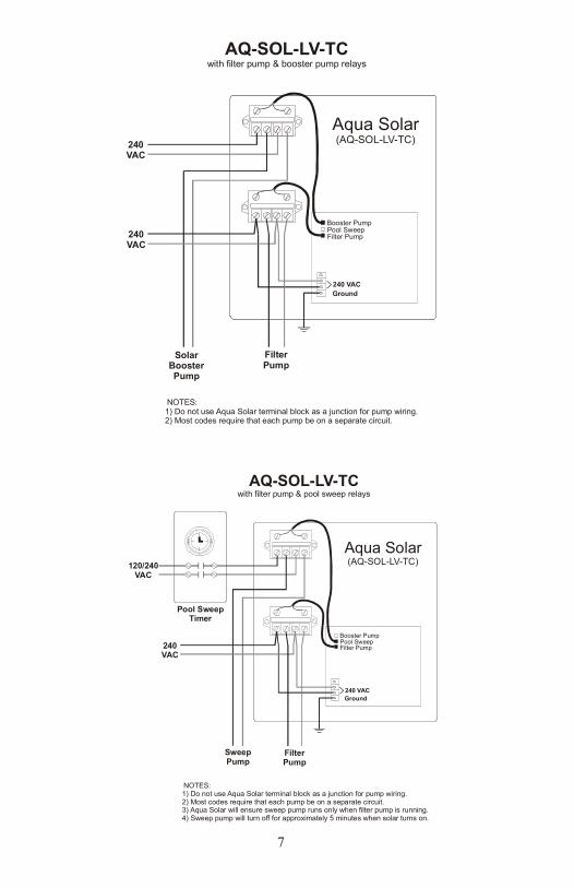
AQ-SOL-LV-TCwith filter pump & booster pump relays
NOTES:1) Do not use Aqua Solar terminal block as a junction for pump wiring.2) Most codes require that each pump be on a separate circuit.
Ground240 VAC
120VAC
Booster PumpPool Sweep
Rev ValveOutput
RelayControlOutputs
InputPower
TemperatureSensorInputs
Fuse (2A, Slo-Blo)
Aux
Filter Pump
Fwd
Pool
Sola
r
240 VAC
Ground
}
Cooling
Recirculate/Freeze Protection
Celsius/Fahrenheit
SolarOverride
(heater interlock for -SP model)
Booster PumpPool SweepFilter Pump240
VAC
FilterPump
SweepPump
Aqua Solar(AQ-SOL-LV-TC)
AQ-SOL-LV-TCwith filter pump & pool sweep relays
NOTES:1) Do not use Aqua Solar terminal block as a junction for pump wiring.2) Most codes require that each pump be on a separate circuit.3) Aqua Solar will ensure sweep pump runs only when filter pump is running.4) Sweep pump will turn off for approximately 5 minutes when solar turns on.
Ground240 VAC
Pool SweepTimer
120/240VAC
6
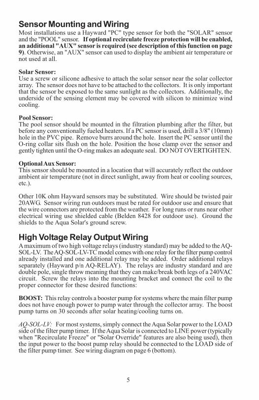
Sensor Mounting and WiringMost installations use a Hayward "PC" type sensor for both the "SOLAR" sensorand the "POOL" sensor. If optional recirculate freeze protection will be enabled,an additional "AUX" sensor is required (see description of this function on page9). Otherwise, an "AUX" sensor can used to display the ambient air temperature ornot used at all.
Solar Sensor:Use a screw or silicone adhesive to attach the solar sensor near the solar collectorarray. The sensor does not have to be attached to the collectors. It is only importantthat the sensor be exposed to the same sunlight as the collectors. Additionally, theunderside of the sensing element may be covered with silicon to minimize windcooling.
Pool Sensor:The pool sensor should be mounted in the filtration plumbing after the filter, butbefore any conventionally fueled heaters. If a PC sensor is used, drill a 3/8" (10mm)hole in the PVC pipe. Remove burrs around the hole. Insert the PC sensor until theO-ring collar sits flush on the hole. Position the hose clamp over the sensor andgently tighten until the O-ring makes an adequate seal. DO NOT OVERTIGHTEN.
Optional Aux Sensor:This sensor should be mounted in a location that will accurately reflect the outdoorambient air temperature (not in direct sunlight, away from heat or cooling sources,etc.).
Other 10K ohm Hayward sensors may be substituted. Wire should be twisted pair20AWG. Sensor wiring run outdoors must be rated for outdoor use and ensure thatthe wire connectors are protected from the weather. For long runs or runs near otherelectrical wiring use shielded cable (Belden 8428 for outdoor use). Ground theshields to the Aqua Solar's ground screw.
High Voltage Relay Output WiringA maximum of two high voltage relays (industry standard) may be added to the AQ-SOL-LV. The AQ-SOL-LV-TC model comes with one relay for the filter pump controlalready installed and one additional relay may be added. Order additional relaysseparately (Hayward p/n AQ-RELAY). The relays are industry standard and aredouble pole, single throw meaning that they can make/break both legs of a 240VACcircuit. Screw the relays into the mounting bracket and connect the coil to theproper connector for these desired functions:
BOOST: This relay controls a booster pump for systems where the main filter pumpdoes not have enough power to pump water through the collector array. The boostpump turns on 30 seconds after solar heating/cooling turns on.
AQ-SOL-LV: For most systems, simply connect the Aqua Solar power to the LOADside of the filter pump timer. If the Aqua Solar is connected to LINE power (typicallywhen "Recirculate Freeze" or "Solar Override" features are also being used), thenthe input power to the boost pump relay should be connected to the LOAD side ofthe filter pump timer. See wiring diagram on page 6 (bottom).
5
Booster PumpPool SweepFilter Pump
Ground
Pool SweepTimer
Contactor(240 VAC Coil)
120/240VAC
240VAC
Filter PumpTimer
Pool FilterPump
Pool SweepPump
Aqua Solar(AQ-SOL-LV)
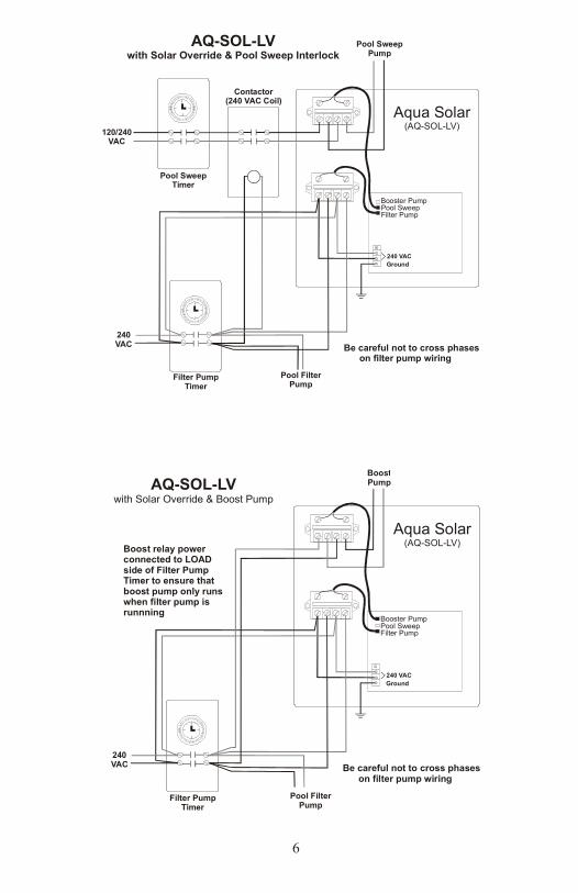
AQ-SOL-LVwith Solar Override & Pool Sweep Interlock
Be careful not to cross phases on filter pump wiring
240 VAC
Booster PumpPool SweepFilter Pump
Ground
240VAC
Filter PumpTimer
Pool FilterPump
BoostPump
Aqua Solar(AQ-SOL-LV)
AQ-SOL-LVwith Solar Override & Boost Pump
Be careful not to cross phases on filter pump wiring
240 VAC
Boost relay powerconnected to LOAD side of Filter PumpTimer to ensure thatboost pump only runswhen filter pump isrunnning
6
Sensor Mounting and WiringMost installations use a Hayward "PC" type sensor for both the "SOLAR" sensorand the "POOL" sensor. If optional recirculate freeze protection will be enabled,an additional "AUX" sensor is required (see description of this function on page9). Otherwise, an "AUX" sensor can used to display the ambient air temperature ornot used at all.
Solar Sensor:Use a screw or silicone adhesive to attach the solar sensor near the solar collectorarray. The sensor does not have to be attached to the collectors. It is only importantthat the sensor be exposed to the same sunlight as the collectors. Additionally, theunderside of the sensing element may be covered with silicon to minimize windcooling.
Pool Sensor:The pool sensor should be mounted in the filtration plumbing after the filter, butbefore any conventionally fueled heaters. If a PC sensor is used, drill a 3/8" (10mm)hole in the PVC pipe. Remove burrs around the hole. Insert the PC sensor until theO-ring collar sits flush on the hole. Position the hose clamp over the sensor andgently tighten until the O-ring makes an adequate seal. DO NOT OVERTIGHTEN.
Optional Aux Sensor:This sensor should be mounted in a location that will accurately reflect the outdoorambient air temperature (not in direct sunlight, away from heat or cooling sources,etc.).
Other 10K ohm Hayward sensors may be substituted. Wire should be twisted pair20AWG. Sensor wiring run outdoors must be rated for outdoor use and ensure thatthe wire connectors are protected from the weather. For long runs or runs near otherelectrical wiring use shielded cable (Belden 8428 for outdoor use). Ground theshields to the Aqua Solar's ground screw.
High Voltage Relay Output WiringA maximum of two high voltage relays (industry standard) may be added to the AQ-SOL-LV. The AQ-SOL-LV-TC model comes with one relay for the filter pump controlalready installed and one additional relay may be added. Order additional relaysseparately (Hayward p/n AQ-RELAY). The relays are industry standard and aredouble pole, single throw meaning that they can make/break both legs of a 240VACcircuit. Screw the relays into the mounting bracket and connect the coil to theproper connector for these desired functions:
BOOST: This relay controls a booster pump for systems where the main filter pumpdoes not have enough power to pump water through the collector array. The boostpump turns on 30 seconds after solar heating/cooling turns on.
AQ-SOL-LV: For most systems, simply connect the Aqua Solar power to the LOADside of the filter pump timer. If the Aqua Solar is connected to LINE power (typicallywhen "Recirculate Freeze" or "Solar Override" features are also being used), thenthe input power to the boost pump relay should be connected to the LOAD side ofthe filter pump timer. See wiring diagram on page 6 (bottom).
5
Booster PumpPool SweepFilter Pump
Ground
Pool SweepTimer
Contactor(240 VAC Coil)
120/240VAC
240VAC
Filter PumpTimer
Pool FilterPump
Pool SweepPump
Aqua Solar(AQ-SOL-LV)
AQ-SOL-LVwith Solar Override & Pool Sweep Interlock
Be careful not to cross phases on filter pump wiring
240 VAC
Booster PumpPool SweepFilter Pump
Ground
240VAC
Filter PumpTimer
Pool FilterPump
BoostPump
Aqua Solar(AQ-SOL-LV)
AQ-SOL-LVwith Solar Override & Boost Pump
Be careful not to cross phases on filter pump wiring
240 VAC
Boost relay powerconnected to LOAD side of Filter PumpTimer to ensure thatboost pump only runswhen filter pump isrunnning
4
INSTALLATIONMountingThe Aqua Solar is designed for outdoor use. Mount the enclosure vertically with theknockouts facing downward. For safety, the Aqua Solar must be a minimum of 5 feet(horizontally) from the pool or spa.
Power inputTurn off power at circuit breaker before wiring. Follow NEC and all local electricalcodes. Wire to either 120VAC or 240VAC per the diagram below. If the Aqua Solaris being powered from the same circuit as one of the pumps, wire to the relay first andthen jumper over the Aqua Solar terminal block. Do NOT use the Aqua Solar termi-nal block as a junction for pump power, the terminal block is not rated for high amps.Be sure to connect the earth ground to the green terminal.
Output wiring to solar diverter valveMost installations use a solar valve, which diverts water through the collector panelswhen solar heat is available. For Hayward, Jandy, and Compool valve actuators (withwire end connectors), two 3-pin connectors are supplied. Plug the actuator into oneof the Aqua Solar's two 3-pin connectors (see diagram above for location of connec-tors). If the valve operates opposite to the way it is supposed to, disconnect and pluginto the other connector.
7
Booster PumpPool SweepFilter Pump240
VAC
240VAC
FilterPump
Solar BoosterPump
Aqua Solar(AQ-SOL-LV-TC)
AQ-SOL-LV-TCwith filter pump & booster pump relays
NOTES:1) Do not use Aqua Solar terminal block as a junction for pump wiring.2) Most codes require that each pump be on a separate circuit.
Ground240 VAC
120VAC
Booster PumpPool Sweep
Rev ValveOutput
RelayControlOutputs
InputPower
TemperatureSensorInputs
Fuse (2A, Slo-Blo)
Aux
Filter Pump
Fwd
Pool
Sola
r
240 VAC
Ground
}
Cooling
Recirculate/Freeze Protection
Celsius/Fahrenheit
SolarOverride
(heater interlock for -SP model)
Booster PumpPool SweepFilter Pump240
VAC
FilterPump
SweepPump
Aqua Solar(AQ-SOL-LV-TC)
AQ-SOL-LV-TCwith filter pump & pool sweep relays
NOTES:1) Do not use Aqua Solar terminal block as a junction for pump wiring.2) Most codes require that each pump be on a separate circuit.3) Aqua Solar will ensure sweep pump runs only when filter pump is running.4) Sweep pump will turn off for approximately 5 minutes when solar turns on.
Ground240 VAC
Pool SweepTimer
120/240VAC
83
TIME CLOCK -- MANUAL CONTROLThe manual control can override the timer and is located at approximately the 4o’clock position.
“1” (up) - pump ON“ ” (center) - timer controls pump“0” (down) - pump OFF
NOTE: If the solar override function is enabled, then the Aqua Solar may keep thefilter pump running even though the time clock is “off”
TEMPERATURE DISPLAYThe temperature display normally displays the pool temperature. Push the small but-ton next to the display to cycle through the various displays. If a temperature sensoris not wired to the Aqua Solar, or the sensor is not functioning properly, the errormessage "Err" will be displayed for that sensor. If the button is not pushed for 30seconds, the display will automatically revert back to pool temperature. The ex-ample below shows a typical display:
Normal, default display indicates Pool temperature:
1st button push will show Solar Collector temperature:
2nd button push will show Aux temperature (if used):
3rd button push will show "Desired Temperature":
4th button push will show software revision number:
5th button push will loop back to show Pool temperature.
LED INDICATORSPower: Input power is applied to the Aqua Solar.Heating: Solar heating is active. If both Heating and Cooling are on, the
switch is in the ON position.Cooling: Nocturnal Cooling is active. If both Heating and Cooling are
on, the switch is in the ON position.Sweep Interlock: The pool sweep is turned OFF for approximately 6 minutes to
allow air to purge from the system.Pool Sensor: A problem is detected with the pool sensor (open or short
circuit).Solar Sensor: A problem is detected with solar sensor (open or short circuit).Aux Sensor: A problem is detected with the AUX sensor (short circuit, only
when used for recirculate freeze protection).
AQ-SOL-LV-TC: The Aqua Solar will automatically ensure that the filter pump isrunning before turning on the boost pump. See wiring diagram on page 7.
SWEEP INTERLOCK: The relay is wired in series with the pool sweep and turns thepool sweep off for approximately 6 minutes whenever the solar turns on. This pre-vents the pool sweep pump from losing prime while air is being purged from the solarcollector array. For model, AQ-SOL-LV-TC the relay will also turn the pool sweep offwhenever the filter pump is turned off. See wiring diagrams on page 6 (top) and onpage 7 (bottom) for typical wiring.
FILTER PUMP: The function of this relay varies with the model of the Aqua Solar. Ifthe "Solar Override" is enabled (see "Jumper Settings"), the Aqua Solar will overridethe time clock and turn the filter pump on when there is a call for solar heating. If"Recirculate Freeze" protection is enabled, the Aqua Solar will turn the pump andsolar valve on during freezing conditions.
AQ-SOL-LV: This relay should be wired in parallel with the filter pump timeclockcontacts as shown on page 6. Be careful to make sure the phases do not get reversed.
AQ-SOL-LV-TC: This relay is the primary control for the filter pump—there is noother timer. The Aqua Solar will operate the filter pump according to the "trippers" seton the built-in timeclock in addition to the optional "Solar Override" and "RecirculateFreeze" options.
Booster PumpPool SweepFilter Pump
120 or 240VAC
240VAC
Aqua Solar(AQ-SOL-LV-SP)
AQ-SOL-LV-SPHEATER INTERLOCK FUNCTION
NOTES:1) Do not use Aqua Solar terminal block as a junction for pump wiring.2) Most codes require that each pump be on a separate circuit.
Ground240 VAC
On when solar offOff when solar on( )
HEATER
NOTE:Connect heater interlockrelay to“Pool Sweep”
OPERATIONThe Aqua Solar is a fully automatic solar heating control which requires minimal setup or adjustment under normal operating conditions. Typically the following is re-quired:
1. Set the main switch to AUTO2. Set the “Desired Temperature” knob to the desired temperature for the pool3. Set the time clock for the correct time, the desired hours of filtration, and
“auto” operation (model AQ-SOL-LV-TC only)
The “Heating” LED will show when the pool is being solar heated. If your pool hasa pool sweep, the Aqua Solar will turn it off for approximately 6 minutes when solarheat is turned on. This will allow air to be purged from the system.
Controls and DisplaysMAIN SWITCH
ON: The Aqua Solar directs water through the solar collectors regardless ofdesired temperature setting. Both the “Heating” and “Cooling” LED’s will beon. For model AQ-SOL-LV-TC, this also turns on the filter pump.
AUTO: For normal operation. In this position, the Aqua Solar will operateautomatically based on the solar and pool temperatures.
OFF: The Aqua Solar ceases solar heating or cooling (if enabled). Recircu-late freeze protection (if enabled) will still operate normally. This switch doesNOT remove power from the unit--to service the equipment, disconnect powerat the main circuit breaker.
DESIRED TEMPERATURESet the desired pool temperature. The digital display will show the exact tempera-ture while rotating the Desired Temperature knob. The display reverts back to thedefault pool temperature display a few seconds later.
TIMECLOCK (model AQ-SOL-LV-TC only)The time clock controls the hours of operation for the filter pump. The pump canbe programmed in 15-minute intervals with multiple on/off periods per day. Per theAssociation of Pool and Spa Professionals (APSP) standards, the pump should runlong enough each day to filter all of the water in the pool each day.
Set the Aqua Solar timeclock to the correct time by rotating the clock dial in aclockwise direction. The internal “hands” show time at a glance and the arrow(approximately 2 o’clock on dial) point indicates AM/PM. Set the pump on/off timeusing the series of small slide "trippers" located around the outside of thetimeclock. Each tripper controls a 15-minute interval.
OFF - Push trippers IN (toward center)ON - Pull trippers OUT (away from center)
29
Jumper SettingsThe jumpers that enable/disable optional control features are located on the right sideof the main circuit board (see page 4). The factory default for all functions is "dis-abled" (each jumper will be on a single pin). To "enable" a function, simply take thedesignated jumper and place it over both pins.
COOLING: A high voltage relay for filter pump control is usually required to imple-ment this function. If Cooling is enabled, the Aqua Solar will cool the pool by turningon the filter pump and diverting the flow through the collector array whenever the"POOL" temperature is WARMER than the “Desired Temperature” setting AND the"SOLAR" sensor is COOLER than the pool water.
RECIRCULATE FREEZE PROTECTION: A high voltage relay connected tothe "FILTER PUMP" output and the AUX temperature sensor are required to imple-ment this function. If enabled, the Aqua Solar will turn the filter pump on and operatethe solar diverter valve whenever freezing conditions are detected (AUX sensor be-low 35ºF). See diagram on page 6 for typical relay wiring. When recirculate freezeprotection is enabled and the Aqua Solar senses a freeze condition at the AUX sensor,it will circulate the pool water continuously through the entire filtration plumbingloop including the solar collector panels. While this type of freeze protection isusually adequate in relatively mild climates, it is extremely important that the AUXsensor be properly placed and that the homeowner realize that the system is unpro-tected in the event of a power failure. Hayward highly recommends that one or more“freeze snap switches” (model GC-3) be placed in areas with susceptible plumbing(example: areas that may be shaded, or get more wind exposure) and that these sen-sors be wired in series with the AUX sensor. Recirculate freeze protection is NOTrecommended in climates where freezing temperatures are common or last forextended periods.
WARNING--If recirculate freeze protection is NOT selected, then you are rely-ing on the collectors naturally draining to provide freeze protection. It is veryimportant that you use a non-positive seal valve or drill a hole in the diverter ofa positive seal valve to allow the collectors to drain. This will NOT work if thecollectors are located below the water level of the pool.
CELSIUS DISPLAY: This will change the temperature display to degrees--Celsius.The factory default is degrees--Fahrenheit.
SOLAR OVERRIDE: A high voltage relay connected to the "FILTER PUMP" outputis required to implement this function. When "Solar Override" is enabled, the AquaSolar will override the filter pump timeclock (external timeclock for AQ-SOL-LV orinternal timeclock for AQ-SOL-LV-TC) and turn the filter pump on whenever there is acall for solar heating or cooling. During periods of on/off cloudy days this may resultin the pump turning on and off multiple times. It is also possible that the pump couldturn on during hot night conditions. To prevent rapid on/off cycling of the filter pumpduring cloudy conditions, the pump will also remain on for a minimum of 10 minutes,and will remain off for a minimum of 2 hours.
101
Aqua Solar Digital Solar Control SystemThe Aqua Solar Digital Solar Control System is a differential temperature control forsolar heating of pools, spas, and hot tubs. The Aqua Solar is available in 3 models;AQ-SOL-LV, AQ-SOL-LV-TC and AQ-SOL-LV-SP. These models provide differentialtemperature control with an adjustable calibrated water temperature high limit. Bothoffer a built-in digital display for solar, water, and ambient temperature information aswell as programmable set point temperature. Automatic nocturnal cooling (for poolsthat overheat in hot climates) and recirculate freeze protection functions can be en-abled/disabled via internal jumpers. The AQ-SOL-LV-TC additionally provides a filterpump time clock, programmable in 15-minute intervals with multiple ON/OFF times.The AQ-SOL-LV-SP model provides a solar priority function—one of the optionalhigh voltage relays can be used to remove power from the conventional heater when-ever solar heating is available. This maximizes the heat contribution from solar. Frontpanel indicator LED’s also provide immediate feedback of system state such as heat-ing, cooling, and sensor fault.
SpecificationsPower: 105-130VAC, .5A 50/60Hz. or
195-250VAC, .3A 50/60Hz
Valve Output: 24VAC, 20VA, .85A max.Industry standard 3 pin connector
Relay Outputs: DPST isolated contacts; 3HP@240V, 1.5HP@120V, booster pump,pool sweep interlock, or filter pump; 1 relay supplied with AQ-SOL-LV-TC, maximum of 2; order relays separately (part no. AQ-RELAY); relays are industry standard
Sensors: 2 required for "SOLAR" and "POOL" temperatures; 3rd sensor("AUX") is optional—for display and/or recirculate freezeprotection; (all sensors are thermistor type, 10K@25ºC/77ºF,additional freeze snap switches may be wired in series with the"AUX" sensor when used for recirculate freeze protection)
Field Selectable optionsC/F Temperature display in Celsius or Fahrenheit (factory default)Cooling Enables or disables (factory default) operation to cool the poolRecirc. Frz. Enables or disables (factory default) recirculate freeze protectionSolar Override Enables or disables (factory default) override of the filter pump
relay when solar heat is available.
Control LogicHeat diff.: 4ºF on, 1.5ºF offHigh Limit: 70-104ºF calibrated scaleRecirc. freeze: On when AUX sensor less than or equal to 34ºF
Off when AUX sensor greater than or equal to 36ºFCool diff.: -8ºF on, -3ºF off
Troubleshooting1. "Power" LED off:Check main power circuit breakers. Check to see if the Aqua Solar power is connectedto the LOAD side of the filter pump timer, in which case the Aqua Solar will only be onwhen the filter pump is on. Lastly, check the internal fuse which is located on the rightupper side of the main circuit board. If necessary, replace the fuse with a type 3AG, 2amp, slo-blo fuse, which is available in most electrical or electronics stores.
2. "Heating" LED is always on:Check that the switch is in the “AUTO” position. Check the sensor temperatures:The "Heating" LED should go off if the pool temperature is less than the "DesiredTemperature" OR if the solar temperature is less than the pool temperature. If thesensors appear to giving incorrect readings, check the sensors using the temperature/resistance/voltage chart on the back cover.
3. "Heating" LED never comes on:Verify that the switch is in the “AUTO” position. Check the sensor temperatures: The"Heating" LED should turn on when the pool temperature is less than the "DesiredTemperature" AND the solar temperature is warmer than the pool temperature. Theexception is when solar override is being used (typically when the pool is filtered atnight, but the solar override function is used to turn the filter pump on during the daywhen solar heat is available): In this case, there is a 2 hour minimum off time to preventrapid on/off cycling of the filter pump. If the sensors appear to giving incorrectreadings, check the sensors using the temperature/resistance/voltage chart on theback cover.
4. "Heating" and "Cooling" LEDs on simultaneouslyThis indicates that the main switch is in the "ON" position. The Aqua Solar willoperate the solar valve and the booster pump (if installed) regardless of the sensortemperatures. Set the switch back to "AUTO" to resume normal operation.
5. "Heating" and "Cooling" LEDs flashing simultaneouslyThis indicates that recirculate freeze protection is active (solar valve on, boost pumpon (if used), and filter pump on) due to the "AUX" sensor being less than 35ºF OR the"AUX" sensor being disconnected OR any freeze snap switches wired in series withthe "AUX" sensor being open. If the "AUX" sensor is not connected OR a freezesnap switch is open, the "AUX" temperature display will be " LO ". The Aqua Solarwill continue this operating mode until the "AUX" sensor rises above 35ºF AND allfreeze snap switches wired in series with the "AUX" sensor are closed. This functionoperates regardless of the position of the "ON / AUTO / OFF" switch.
6. "Pool Sensor" LED on or flashing "Err" on the pool temperature display:
11
On continuously indicates a probable open circuit in the "POOL" sensor or wiring.Flashing indicates a probable short circuit in the "POOL" sensor or wiring. In eithercase digital pool temperature display will show as "PErr". The solar heating andcooling functions will remain off until this problem is fixed, however, the recirculatefreeze protection (if enabled by the jumper) will still operate properly. Use the chart onthe back cover to check the "POOL" sensor with a voltmeter (you don't need todisconnect the sensor). Alternatively, you can disconnect the sensor and measurethe sensor resistance. Replace the sensor or fix the wiring as required. If the sensorand wiring are both good, then the main circuit PCB may have a problem.
7. "Solar Sensor" LED on or flashing "Err" on the solar temperature display:On continuously indicates a probable open circuit in the "SOLAR" sensor or wiring.Flashing indicates a probable short circuit in the "SOLAR" sensor or wiring. In eithercase digital pool temperature display for the "SOLAR" sensor will show as "CErr".The solar heating and cooling functions will remain off until this problem is fixed,however, the recirculate freeze protection (if enabled by the jumper) will still operateproperly.
Use the chart on the back cover to check the "SOLAR" sensor with a voltmeter (youdon't need to disconnect the sensor). Alternatively, you can disconnect the sensor andmeasure the sensor resistance. Replace the sensor or fix the wiring as required. If thesensor and wiring are both good, then the main circuit PCB may have a problem.
8. "Aux Sensor" LED flashing "Err" on the Aux temperature display:Flashing indicates a probable short circuit in the "AUX" sensor or wiring. The digitalpool temperature display for the "AUX" sensor will show as "AErr". This errorindication only occurs when the "AUX" sensor is being used for recirculate freezeprotection. When the Aux sensor is shorted, the Aqua Solar will use the "SOLAR"sensor as a backup freeze sensor and turn the recirculate freeze protection on whenthe temperature is less than 60ºF.
Use the chart on the back cover to check the "AUX" sensor with a voltmeter (youdon't need to disconnect the sensor). Alternatively, you can disconnect the sensor andmeasure the sensor resistance. Replace the sensor or fix the wiring as required. If thesensor and wiring are both good, then the main circuit PCB may have a problem.
Table of Contents
SPECIFICATIONSSPECIFICATIONSSPECIFICATIONSSPECIFICATIONSSPECIFICATIONSSpecifications Specifications Specifications Specifications Specifications ......................................................................1
OPERATIONOPERATIONOPERATIONOPERATIONOPERATIONControls Controls Controls Controls Controls ...............................................................................2
Temperature Display Temperature Display Temperature Display Temperature Display Temperature Display ........................................................3
INSTALLATIONINSTALLATIONINSTALLATIONINSTALLATIONINSTALLATIONMounting Mounting Mounting Mounting Mounting ..............................................................................4
Wiring Wiring Wiring Wiring Wiring ..................................................................................4
Jumper Settings Jumper Settings Jumper Settings Jumper Settings Jumper Settings ..................................................................9
TROUBLESHOOTINGTROUBLESHOOTINGTROUBLESHOOTINGTROUBLESHOOTINGTROUBLESHOOTINGTroubleshooting Troubleshooting Troubleshooting Troubleshooting Troubleshooting ...............................................................10
WARRANTYWARRANTYWARRANTYWARRANTYWARRANTYWarrantyWarrantyWarrantyWarrantyWarranty.............................................................................12
12
IMPORTANT SAFETY INSTRUCTIONSWhen using this electrical equipment, basic safety precautions should always befollowed, including the following:
• READ AND FOLLOW ALL INSTRUCTIONS
• Disconnect all AC power during installation.
• Warning – To reduce the risk of injury do not permit children to use thisproduct unless they are closely supervised at all times.
• A green colored terminal marked “EARTH” is located inside the wiringcompartment. To reduce the risk of electrical shock, this terminal must beconnected to the grounding means provided in the electrical supplyservice panel with a continuous copper wire equivalent in size to thecircuit conductors supplying the equipment.
• All field installed metal components such as rails, ladders, drains, or othersimilar hardware within 3 meters of the pool, spa or hot tub shall bebonded to the equipment grounding bus with copper conductors notsmaller than 8 AWG US/ 6 AWG Canada.
SAVE THESE INSTRUCTIONS
5-Year Limited Solar WarrantyThis Five Year Limited Warranty statement is only applicable to Solar controls and accessoriessold and installed within the USA and Canada* and supersedes any warranty statements datedprior to November 1, 2010.
Hayward warrants its Hayward solar products to be free from defects in material or workmanship,under normal use and service for 5 years from date of manufacture, providing it is installedaccording to the installation instructions and specifications. The datecode stamped on theoutside of the product and also coded on the printed circuit board will be the sole determinationof manufacturing date.
To obtain warranty service or repair, please contact the place of purchase or the nearest Haywardauthorized warranty service center. For more information, please contact the HaywardTechnical Service Support Center or visit us on the web at www.haywardnet.com. Hayward willnot assume any of the cost incurred in removal or reinstallation of the product. One year outsidethe USA and Canada.
The express warranty above constitutes the entire warranty of Hayward Pool Products withrespect to its solar products and IS IN LIEU OF ALL OTHER WARRANTIES, EXPRESSEDOR IMPLIED, INCLUDING A WARRANTY OF FITNESS FOR A PARTICULAR PURPOSE.IN NO EVENT SHALL HAYWARD BE RESPONSIBLE OR ANY CONSEQUENTIAL ORINCIDENTAL DAMAGES OF ANY NATURE WHATSOEVER.
No wholesaler, agent, dealer, contractor, or other person is authorized to give any warranty onbehalf of Hayward. This warranty is void if the product has been altered in any way after leavingthe factory.
ChargesYears 1-3:no chargeYears 4-5 60% of current list price plus $5.00 shipping and handling
Unless a copy of the original purchase invoice is enclosed, the manufacturing datecode on theproduct will be used to determine the repair charges. Hayward reserves the right to charge anominal fee to cover inspection, test, and return freight for all controls where no faults orproblems are detected. All charges will be COD (COD charge will be included) unless you alreadyhave an open account in good standing with Hayward. If the product returned can not berepaired, Hayward will offer and equivalent credit towards the purchase of any new Haywardproduct. Products that exhibit evidence of abuse, misuse, field damage (water/fire damage, linevoltage applied to low voltage terminals, missing parts, etc.) or installed for more than thewarranty period are not eligible for warranty repair replacement.
Temperature/Resistance /VoltageAll Hayward controls use a 10K thermistor sensors. When disconnected from thecontrol, the sensor will read 10K ohms at 25ºC/77ºF. Refer to the chart below forthe resistance at other temperatures. For a given temperature, the resistancereading should be accurate to ±1%. For a given resistance reading, the tempera-ture reading should be accurate to ±0.5ºF. All voltage measurements (DC) mustbe made with the sensor connected to the control and should be accurate to ± 2%.
°F Ohms Volts °F Ohms Volts °F Ohms Volts °F Ohms Volts1 82,719 4.46 41 25,391 3.59 81 9,076 2.38 121 3,679 1.342 80,142 4.45 42 24,704 3.56 82 8,861 2.35 122 3,602 1.323 77,656 4.43 43 24,037 3.53 83 8,651 2.32 123 3,527 1.304 75,255 4.41 44 23,391 3.50 84 8,447 2.29 124 3,454 1.285 72,937 4.40 45 22,764 3.47 85 8,249 2.26 125 3,382 1.266 70,698 4.38 46 22,156 3.45 86 8,056 2.23 126 3,312 1.247 68,535 4.36 47 21,566 3.42 87 7,867 2.20 127 3,244 1.228 66,447 4.35 48 20,993 3.39 88 7,684 2.17 128 3,177 1.219 64,428 4.33 49 20,438 3.36 89 7,506 2.14 129 3,112 1.19
10 62,479 4.31 50 19,900 3.33 90 7,333 2.12 130 3,049 1.1711 60,595 4.29 51 19,377 3.30 91 7,164 2.09 131 2,987 1.1512 58,774 4.27 52 18,870 3.27 92 6,999 2.06 132 2,926 1.1313 57,014 4.25 53 18,377 3.24 93 6,839 2.03 133 2,867 1.1114 55,313 4.23 54 17,899 3.21 94 6,683 2.00 134 2,809 1.1015 53,669 4.21 55 17,435 3.18 95 6,530 1.98 135 2,752 1.0816 52,078 4.19 56 16,985 3.15 96 6,382 1.95 136 2,697 1.0617 50,541 4.17 57 16,548 3.12 97 6,238 1.92 137 2,643 1.0518 49,054 4.15 58 16,123 3.09 98 6,097 1.89 138 2,591 1.0319 47,616 4.13 59 15,711 3.06 99 5,960 1.87 139 2,539 1.0120 46,225 4.11 60 15,310 3.02 100 5,827 1.84 140 2,489 1.0021 44,879 4.09 61 14,921 2.99 101 5,697 1.81 141 2,440 0.9822 43,577 4.07 62 14,543 2.96 102 5,570 1.79 142 2,392 0.9723 42,318 4.04 63 14,176 2.93 103 5,446 1.76 143 2,345 0.9524 41,099 4.02 64 13,820 2.90 104 5,326 1.74 144 2,299 0.9325 39,919 4.00 65 13,473 2.87 105 5,208 1.71 145 2,254 0.9226 38,777 3.97 66 13,136 2.84 106 5,094 1.69 146 2,210 0.9027 37,671 3.95 67 12,809 2.81 107 4,982 1.66 147 2,167 0.8928 36,601 3.93 68 12,491 2.78 108 4,873 1.64 148 2,125 0.8829 35,565 3.90 69 12,182 2.75 109 4,767 1.61 149 2,084 0.8630 34,561 3.88 70 11,882 2.72 110 4,664 1.59 150 2,044 0.8531 33,590 3.85 71 11,589 2.68 111 4,563 1.57 151 2,005 0.8432 32,648 3.83 72 11,305 2.65 112 4,464 1.54 152 1,966 0.8233 31,737 3.80 73 11,029 2.62 113 4,368 1.52 153 1,929 0.8134 30,853 3.78 74 10,761 2.59 114 4,274 1.50 154 1,892 0.8035 29,998 3.75 75 10,500 2.56 115 4,183 1.47 155 1,856 0.7836 29,169 3.72 76 10,246 2.53 116 4,094 1.45 156 1,821 0.7737 28,365 3.70 77 9,999 2.50 117 4,007 1.43 157 1,787 0.7638 27,587 3.67 78 9,758 2.47 118 3,922 1.41 158 1,753 0.7539 26,832 3.64 79 9,525 2.44 119 3,839 1.39 159 1,720 0.7340 26,100 3.61 80 9,297 2.41 120 3,758 1.37 160 1,688 0.72
Electronic Solar Control Center
Operation and InstallationManualAQ-SOL-LV
AQ-SOL-LV-TCAQ-SOL-LV-SP
092008F RevGCopyright © 2010 Hayward Inc. www.haywardnet.com620 Division St.
Elizabeth, NJ 07207
Aqua Solar