Embed Size (px)
Citation preview
NEW Product
1
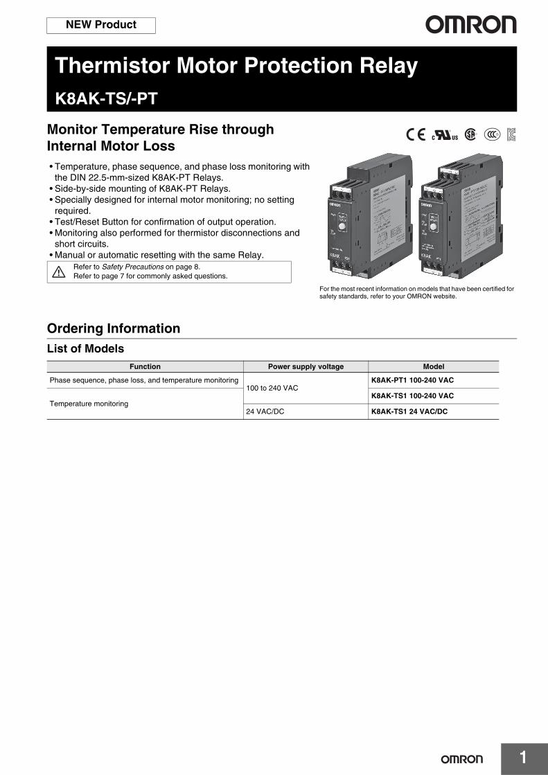
Thermistor Motor Protection RelayK8AK-TS/-PT
Monitor Temperature Rise through Internal Motor Loss• Temperature, phase sequence, and phase loss monitoring with
the DIN 22.5-mm-sized K8AK-PT Relays.• Side-by-side mounting of K8AK-PT Relays.• Specially designed for internal motor monitoring; no setting
required.• Test/Reset Button for confirmation of output operation.• Monitoring also performed for thermistor disconnections and
short circuits.• Manual or automatic resetting with the same Relay.
Ordering InformationList of Models
Refer to Safety Precautions on page 8.Refer to page 7 for commonly asked questions.
For the most recent information on models that have been certified for safety standards, refer to your OMRON website.
Function Power supply voltage Model
Phase sequence, phase loss, and temperature monitoring100 to 240 VAC
K8AK-PT1 100-240 VAC
Temperature monitoringK8AK-TS1 100-240 VAC
24 VAC/DC K8AK-TS1 24 VAC/DC
K8AK-TS/-PT
2
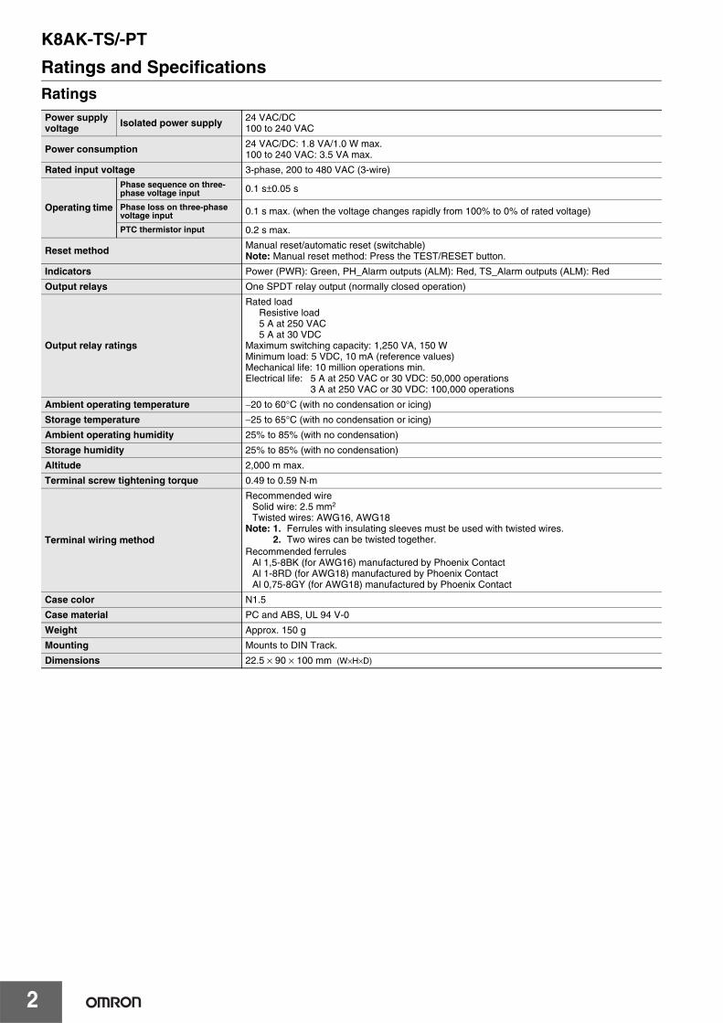
Ratings and SpecificationsRatingsPower supply voltage Isolated power supply 24 VAC/DC
100 to 240 VAC
Power consumption 24 VAC/DC: 1.8 VA/1.0 W max.100 to 240 VAC: 3.5 VA max.
Rated input voltage 3-phase, 200 to 480 VAC (3-wire)
Operating time
Phase sequence on three-phase voltage input 0.1 s±0.05 s
Phase loss on three-phase voltage input 0.1 s max. (when the voltage changes rapidly from 100% to 0% of rated voltage)
PTC thermistor input 0.2 s max.
Reset method Manual reset/automatic reset (switchable)Note: Manual reset method: Press the TEST/RESET button.
Indicators Power (PWR): Green, PH_Alarm outputs (ALM): Red, TS_Alarm outputs (ALM): Red
Output relays One SPDT relay output (normally closed operation)
Output relay ratings
Rated loadResistive load5 A at 250 VAC5 A at 30 VDC
Maximum switching capacity: 1,250 VA, 150 WMinimum load: 5 VDC, 10 mA (reference values)Mechanical life: 10 million operations min.Electrical life: 5 A at 250 VAC or 30 VDC: 50,000 operations
3 A at 250 VAC or 30 VDC: 100,000 operations
Ambient operating temperature −20 to 60°C (with no condensation or icing)
Storage temperature −25 to 65°C (with no condensation or icing)
Ambient operating humidity 25% to 85% (with no condensation)
Storage humidity 25% to 85% (with no condensation)
Altitude 2,000 m max.
Terminal screw tightening torque 0.49 to 0.59 N·m
Terminal wiring method
Recommended wireSolid wire: 2.5 mm2
Twisted wires: AWG16, AWG18Note: 1. Ferrules with insulating sleeves must be used with twisted wires.
2. Two wires can be twisted together.Recommended ferrules
Al 1,5-8BK (for AWG16) manufactured by Phoenix ContactAl 1-8RD (for AWG18) manufactured by Phoenix ContactAl 0,75-8GY (for AWG18) manufactured by Phoenix Contact
Case color N1.5
Case material PC and ABS, UL 94 V-0
Weight Approx. 150 g
Mounting Mounts to DIN Track.
Dimensions 22.5 × 90 × 100 mm (W×H×D)
K8AK-TS/-PT
3
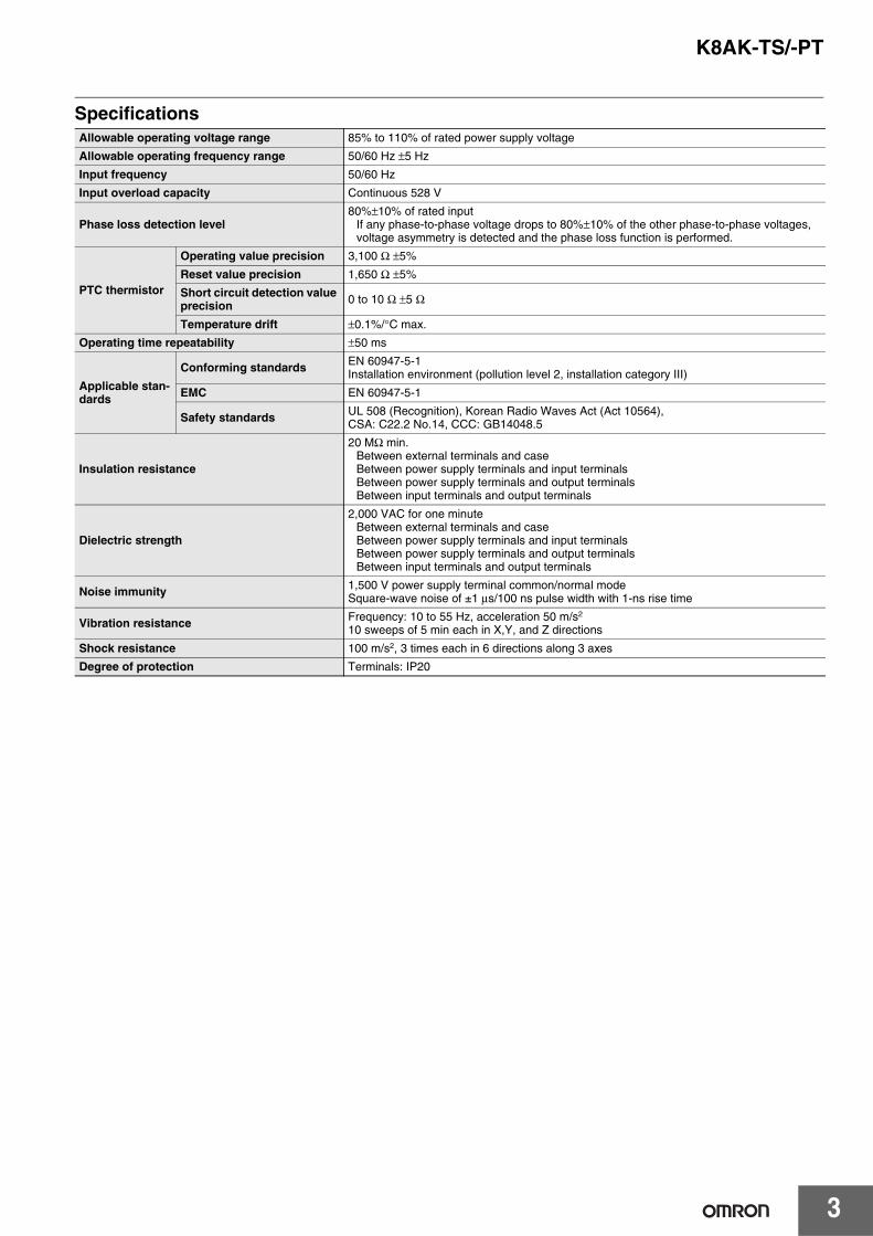
SpecificationsAllowable operating voltage range 85% to 110% of rated power supply voltage
Allowable operating frequency range 50/60 Hz ±5 Hz
Input frequency 50/60 Hz
Input overload capacity Continuous 528 V
Phase loss detection level80%±10% of rated input
If any phase-to-phase voltage drops to 80%±10% of the other phase-to-phase voltages, voltage asymmetry is detected and the phase loss function is performed.
PTC thermistor
Operating value precision 3,100 Ω ±5%
Reset value precision 1,650 Ω ±5%
Short circuit detection value precision 0 to 10 Ω ±5 Ω
Temperature drift ±0.1%/°C max.
Operating time repeatability ±50 ms
Applicable stan-dards
Conforming standards EN 60947-5-1Installation environment (pollution level 2, installation category III)
EMC EN 60947-5-1
Safety standards UL 508 (Recognition), Korean Radio Waves Act (Act 10564), CSA: C22.2 No.14, CCC: GB14048.5
Insulation resistance
20 MΩ min.Between external terminals and caseBetween power supply terminals and input terminalsBetween power supply terminals and output terminalsBetween input terminals and output terminals
Dielectric strength
2,000 VAC for one minuteBetween external terminals and caseBetween power supply terminals and input terminalsBetween power supply terminals and output terminalsBetween input terminals and output terminals
Noise immunity 1,500 V power supply terminal common/normal modeSquare-wave noise of ±1 µs/100 ns pulse width with 1-ns rise time
Vibration resistance Frequency: 10 to 55 Hz, acceleration 50 m/s2
10 sweeps of 5 min each in X,Y, and Z directions
Shock resistance 100 m/s2, 3 times each in 6 directions along 3 axes
Degree of protection Terminals: IP20
K8AK-TS/-PT
4
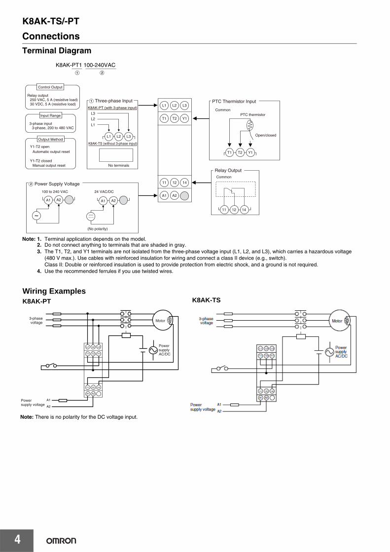
ConnectionsTerminal Diagram
Note: 1. Terminal application depends on the model.2. Do not connect anything to terminals that are shaded in gray.3. The T1, T2, and Y1 terminals are not isolated from the three-phase voltage input (L1, L2, and L3), which carries a hazardous voltage
(480 V max.). Use cables with reinforced insulation for wiring and connect a class II device (e.g., switch). Class II: Double or reinforced insulation is used to provide protection from electric shock, and a ground is not required.
4. Use the recommended ferrules if you use twisted wires.
Wiring Example
Note: There is no polarity for the DC voltage input.
L1 L2 L3
A1 A2
11 12
Control Output
Input Range
Output Method
Relay output250 VAC, 5 A (resistive load)30 VDC, 5 A (resistive load)
PTC thermistorCommon
Open/closed
14
T1 T2 Y1
PTC Thermistor Input
B Power Supply Voltage
100 to 240 VAC 24 VAC/DC
(No polarity)
K8AK-TS (without 3-phase input)
K8AK-PT (with 3-phase input)
No terminals
A Three-phase Input
Y1-T2 openAutomatic output reset
Y1-T2 closedManual output reset
3-phase input3-phase, 200 to 480 VAC
K8AK-PT1 100-240VACA B
T1 T2 Y1
L1
L1
L2
L3
L2 L3
A1 A2 A1 A2
Common
Relay Output
11 12 14
3-phase voltage
Power supply voltage
A1 A2
11 12 14
L1 L2 L3
T1 T2 Y1
A1
A2
Motor
Power supply AC/DC
Wiring Examples K8AK-PT
K8AK-TS
Note: There is no polarity for the DC voltage input.
K8AK-TS/-PT
5
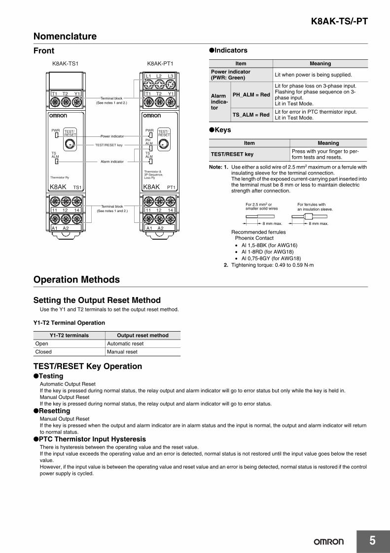
NomenclatureFront Indicators
Keys
Note: 1. Use either a solid wire of 2.5 mm2 maximum or a ferrule with insulating sleeve for the terminal connection.The length of the exposed current-carrying part inserted into the terminal must be 8 mm or less to maintain dielectric strength after connection.
Recommended ferrulesPhoenix Contact• Al 1,5-8BK (for AWG16)• Al 1-8RD (for AWG18)• Al 0,75-8GY (for AWG18)
2. Tightening torque: 0.49 to 0.59 N·m
Operation Methods
Setting the Output Reset MethodUse the Y1 and T2 terminals to set the output reset method.
Y1-T2 Terminal Operation
TEST/RESET Key OperationTesting
Automatic Output ResetIf the key is pressed during normal status, the relay output and alarm indicator will go to error status but only while the key is held in.Manual Output ResetIf the key is pressed during normal status, the relay output and alarm indicator will go to error status.
ResettingManual Output ResetIf the key is pressed when the output and alarm indicator are in alarm status and the input is normal, the output and alarm indicator will return to normal status.
PTC Thermistor Input HysteresisThere is hysteresis between the operating value and the reset value.If the input value exceeds the operating value and an error is detected, normal status is not restored until the input value goes below the reset value.However, if the input value is between the operating value and reset value and an error is being detected, normal status is restored if the control power supply is cycled.
Power indicator
Alarm indicator
Terminal block(See notes 1 and 2.)
Terminal block(See notes 1 and 2.)
T1 T2 Y1
11 12 14
2A 1A 2A 1A
T1 T2 Y1
L1 L2 L3
11 12 14
PHALM
PWR
TSALM
Thermistor &3P-Sequence,Loss Ry
TEST/RESET
PT1
PWR
TSALM
Thermistor Ry
TEST/RESET
TS1 K8AKK8AK
K8AK-TS1 K8AK-PT1
TEST/RESET key
Item Meaning
Power indicator (PWR: Green) Lit when power is being supplied.
Alarm indica-tor
PH_ALM = Red
Lit for phase loss on 3-phase input.Flashing for phase sequence on 3-phase input.Lit in Test Mode.
TS_ALM = Red Lit for error in PTC thermistor input.Lit in Test Mode.
Item Meaning
TEST/RESET key Press with your finger to per-form tests and resets.
For 2.5 mm2 or smaller solid wires
For ferrules with an insulation sleeve.
8 mm max. 8 mm max.
Y1-T2 terminals Output reset method
Open Automatic reset
Closed Manual reset
K8AK-TS/-PT
6
Timing ChartsAutomatic Output Reset (Y1-T2: Open)
Test Mode
Manual Output Reset (Y1-T2: Closed)
Using Y1-T2 as Remote Reset Terminals
Note: 1. It requires 0.1 s for the contacts to switch after the input status is detected. This is not shown in the diagram.2. There are two types of error detection for the three-phase input. The indicator behavior changes accordingly.
Phase loss detected: PH_ALM lights.Phase sequence detected: PH_ALM flashes.
If both a phase loss and phase sequence are detected at the same time, phase loss takes priority.
Dimensions (Unit: mm)
Thermistor Motor Protection Relays
Normal
3,100 Ω
1,650 Ω
10 ΩNot pressed.
t1t1: Power ON lock (0.6 s)
Error
TS_ALM
PH_ALM
Relay contacts (11-14)
TEST/RESET key
PTC thermistor input
Three-phase input error
Power supply voltage
Relay contacts (11-14)
Manual output resetY1-T2 closed.* Automatic output reset
Normal
3,100 Ω
1,650 Ω
10 Ω
t1* Test Mode can be used during normal status. Error status is entered when the TEST/RESET key is
pressed. The method to restore normal status is linked to the
output reset method.
TS_ALM
PH_ALM
TEST/RESET key
PTC thermistor input
Three-phase input error
Power supply voltage
Normal
t1: Power ON lock (0.6 s)
Normal
3,100 Ω
1,650 Ω
10 ΩNot pressed.
t1
Error
TS_ALM
PH_ALM
Relay contacts (11-14)
TEST/RESET key
PTC thermistor input
Three-phase input error
Power supply voltage
t1: Power ON lock (0.6 s)
OpenClosed
Y1-T2 closed.*
* Output Reset Mode is entered when Y1-T1 closes.The latched error status is cleared.When Y1-T2 opens again, the initial status is restored.
3,100 Ω
1,650 Ω
10 Ω
t1
TS_ALM
PH_ALM
Relay contacts (11-14)
TEST/RESET key
PTC thermistor input
Three-phase input error
Power supply voltage
t1: Power ON lock (0.6 s)
T1 T2 Y1
11 12 14
2A 1A 2A 1A
T1 T2 Y1
L1 L2 L3
11 12 14
PHALM
PWR
TSALM
Thermistor &3P-Sequence,Loss Ry
TEST/RESET
PT1
PWR
TSALM
Thermistor Ry
TEST/RESET
TS1 K8AKK8AK
22.522.5 100
90
572
K8AK-TS1K8AK-PT1
K8AK-TS1 K8AK-PT1
K8AK-TS/-PT
7
Checking Operation
PTC Thermistor Input OperationOperating Value
The input resistance gradually increases from around 1 kΩ. The operating value is the input value for which the alarm indicator (TS_ALM) lights. The contact outputs switch simultaneously so that you can confirm operation.
Note: Refer to the timing charts for the operating methods for reference.
Can phase loss be detected on the load side?
In principle, phase loss cannot be detected on the load side because the K8AK-PT1 measures three-phase voltage to determine phase loss.
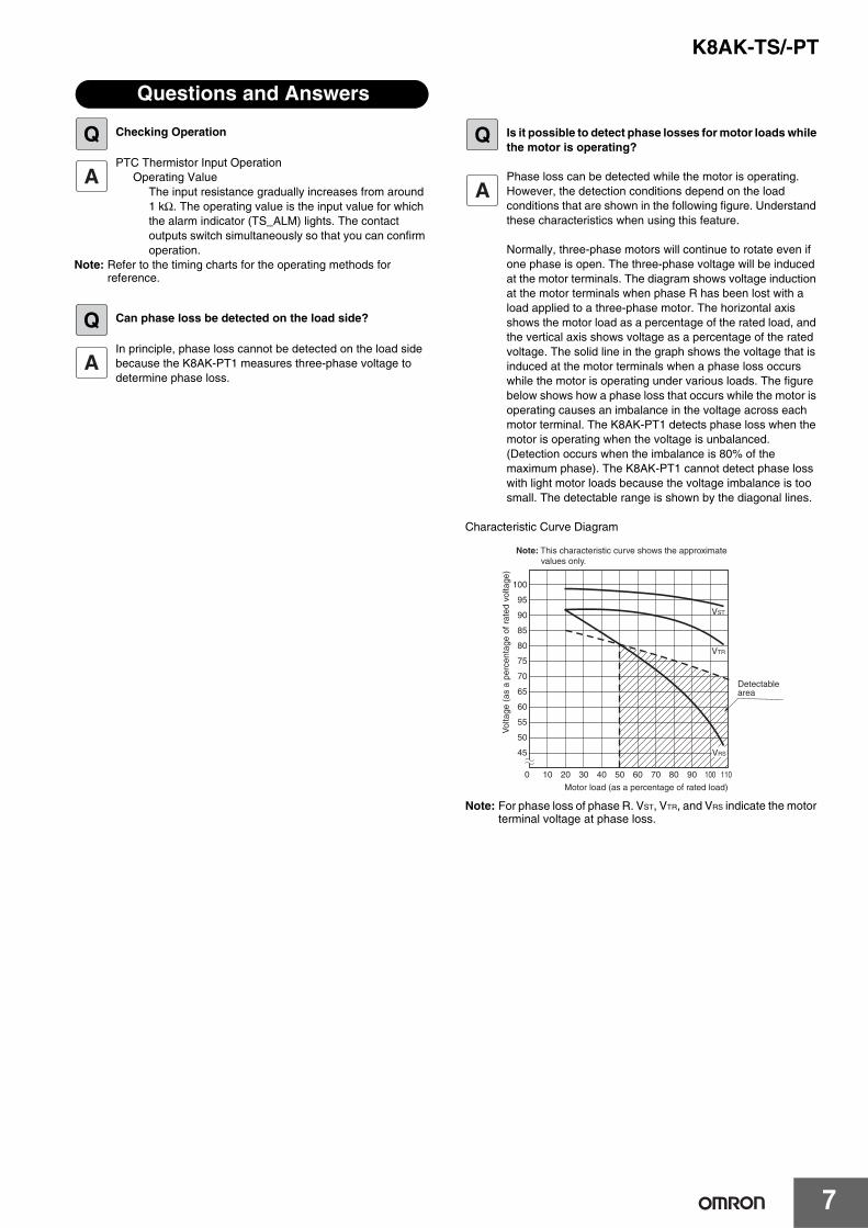
Is it possible to detect phase losses for motor loads while the motor is operating?
Phase loss can be detected while the motor is operating. However, the detection conditions depend on the load conditions that are shown in the following figure. Understand these characteristics when using this feature.
Normally, three-phase motors will continue to rotate even if one phase is open. The three-phase voltage will be induced at the motor terminals. The diagram shows voltage induction at the motor terminals when phase R has been lost with a load applied to a three-phase motor. The horizontal axis shows the motor load as a percentage of the rated load, and the vertical axis shows voltage as a percentage of the rated voltage. The solid line in the graph shows the voltage that is induced at the motor terminals when a phase loss occurs while the motor is operating under various loads. The figure below shows how a phase loss that occurs while the motor is operating causes an imbalance in the voltage across each motor terminal. The K8AK-PT1 detects phase loss when the motor is operating when the voltage is unbalanced. (Detection occurs when the imbalance is 80% of the maximum phase). The K8AK-PT1 cannot detect phase loss with light motor loads because the voltage imbalance is too small. The detectable range is shown by the diagonal lines.
Characteristic Curve Diagram
Note: For phase loss of phase R. VST, VTR, and VRS indicate the motor terminal voltage at phase loss.
Questions and Answers
Q
Q
Q
100
95
90
85
80
75
70
65
60
55
50
45
10 0 20 30 40 50 60 70 80 90 100 110
VST
VTR
VRS
Note: This characteristic curve shows the approximate values only.
Vol
tage
(as
a p
erce
ntag
e of
rat
ed v
olta
ge)
Motor load (as a percentage of rated load)
Detectablearea
K8AK-TS/-PT
8
Safety Precautions
Be sure to read the precautions for all models in the website at the following URL: http://www.ia.omron.com/.
Warning Indications
Meaning of Product Safety Symbols
Electrical shock may occasionally cause serious injury. Confirm that the input voltage is OFF before starting any wiring work and wire all connections correctly.
Electrical shock may cause minor injury.Do not touch terminals while electricity is being supplied.
There is a risk of minor electrical shock, fire, or device failure. Do not allow any pieces of metal, conductors, or cutting chips that occur during the installation process to enter the product.
Explosions may cause minor injuries. Do not use the product in locations with inflammable or explosive gases.
There is a risk of minor electrical shock, fire, or device failure. Do not disassemble, modify, repair, or touch the inside of the product.
Loose screws may cause fires. Tighten terminal screws to the specified torque of 0.49 to 0.59 N·m.
Use of excessive torque may damage the terminal screws. Tighten terminal screws to the specified torque of 0.49 to 0.59 N·m.
Use of the product beyond its life may result in contact welding or burning. Make sure to consider the actual operating conditions and use the product within its rated load and electrical life count. The life of the output relay varies significantly with the switching capacity and switching conditions.
WARNING
Indicates a potentially hazardous situation which, if not avoided, will result in minor or moderate injury, or may result in serious injury or death. Additionally there may be significant property damage.
CAUTIONIndicates a potentially hazardous situation which, if not avoided, may result in minor or moderate injury or in property damage.
Precautions for Safe Use
Supplementary comments on what to do or avoid doing, to use the product safely.
Precautions for Correct Use
Supplementary comments on what to do or avoid doing, to prevent failure to operate, malfunction, or undesirable effects on product performance.
Used to warn of the risk of electric shock under specific conditions.
Used for general prohibitions for which there is no specific symbol.
Used to indicate prohibition when there is a risk of minor injury from electrical shock or other source if the product is disassembled.
Used for general mandatory action precautions for which there is no specified symbol.
WARNING
CAUTION
K8AK-TS/-PT
9
1. Do not use or store the product in the following locations.• Locations subject to water or oil
• Outdoor locations or under direct sunlight
• Locations subject to dust or corrosive gases (particularly sulfurizing gases, ammonia, etc.)
• Locations subject to rapid temperature changes
• Locations prone to icing and dew condensation
• Locations subject to excessive vibration or shock
• Locations subject to wind and rain
• Locations subject to static electricity and noise
• Habitats of insects or small animals
2. Use and store the product in a location where the ambient temperature and humidity are within the specified ranges. If applicable, provide forced cooling.
3. Mount the product in the correct direction.4. Check terminal polarity when wiring and wire all connections
correctly. The power supply terminals do not have polarity.5. Do not wire the input and output terminals incorrectly.6. Make sure the power supply voltage and loads are within the
specifications and ratings for the product.7. Make sure the crimp terminals for wiring are of the specified size.8. Do not connect anything to terminals that are not being used.9. Use a power supply that will reach the rated voltage within 1
second after the power is turned ON.10.Keep wiring separate from high voltages and power lines that
draw large currents. Do not place product wiring in parallel with or in the same path as high-voltage or high-current lines.
11.Do not install the product near equipment that generates high frequencies or surges.
12.The product may cause incoming radio wave interference. Do not use the product near radio wave receivers.
13.Install an external switch or circuit breaker and label it clearly so that the operator can quickly turn OFF the power supply.
14.Make sure the indicators operate correctly. Depending on the application environment, the indicators may deteriorate prematurely and become difficult to see.
15.Do not use the product if it is accidentally dropped. The internal components may be damaged.
16.Be sure you understand the contents of this catalog and handle the product according to the instructions provided.
17.Do not install the product in any way that would place a load on it.18.When discarding the product, properly dispose of it as industrial
waste.19.When using the product, remember that the power supply
terminals carry a high voltage.20.The product must be handled only by trained electrician.21.Prior to operation, check the wiring before you supply power to
the product.22.Do not install the product immediately next to heat sources.23.Perform periodic maintenance.
Observe the following operating methods to prevent failure and malfunction.1. Use the power supply voltage, input power, and other power
supplies and converters with suitable capacities and rated outputs.
2. When cleaning the product, do not use thinners or solvents. Use commercial alcohol.
3. The distortion in the input waveform must be 30% max. If the input waveform is distorted beyond this level, it may cause unnecessary operation.
4. The product cannot be used for thyristor control or on the secondary side of an inverter. To use the product on the secondary side of an inverter, install a noise filter on the primary side of the inverter.
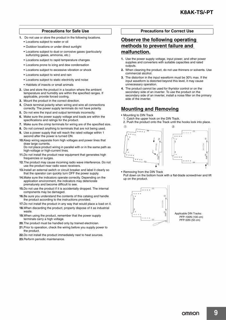
Mounting and Removing• Mounting to DIN Track
1. Catch the upper hook on the DIN Track.2. Push the product onto the Track until the hooks lock into place.
• Removing from the DIN TrackPull down on the bottom hook with a flat-blade screwdriver and lift up on the product.
Precautions for Safe Use Precautions for Correct Use
A B
PFP-100N (100 cm)PFP-50N (50 cm)
Applicable DIN Tracks:

MEMO
10
Terms and Conditions of Sale1. Offer; Acceptance. These terms and conditions (these "Terms") are deemed
part of all quotes, agreements, purchase orders, acknowledgments, price lists,catalogs, manuals, brochures and other documents, whether electronic or inwriting, relating to the sale of products or services (collectively, the "Products")by Omron Electronics LLC and its subsidiary companies (“Omron”). Omronobjects to any terms or conditions proposed in Buyer’s purchase order or otherdocuments which are inconsistent with, or in addition to, these Terms.
2. Prices; Payment Terms. All prices stated are current, subject to change with-out notice by Omron. Omron reserves the right to increase or decrease priceson any unshipped portions of outstanding orders. Payments for Products aredue net 30 days unless otherwise stated in the invoice.
3. Discounts. Cash discounts, if any, will apply only on the net amount of invoicessent to Buyer after deducting transportation charges, taxes and duties, and willbe allowed only if (i) the invoice is paid according to Omron’s payment termsand (ii) Buyer has no past due amounts.
4. Interest. Omron, at its option, may charge Buyer 1-1/2% interest per month orthe maximum legal rate, whichever is less, on any balance not paid within thestated terms.
5. Orders. Omron will accept no order less than $200 net billing. 6. Governmental Approvals. Buyer shall be responsible for, and shall bear all
costs involved in, obtaining any government approvals required for the impor-tation or sale of the Products.
7. Taxes. All taxes, duties and other governmental charges (other than generalreal property and income taxes), including any interest or penalties thereon,imposed directly or indirectly on Omron or required to be collected directly orindirectly by Omron for the manufacture, production, sale, delivery, importa-tion, consumption or use of the Products sold hereunder (including customsduties and sales, excise, use, turnover and license taxes) shall be charged toand remitted by Buyer to Omron.
8. Financial. If the financial position of Buyer at any time becomes unsatisfactoryto Omron, Omron reserves the right to stop shipments or require satisfactorysecurity or payment in advance. If Buyer fails to make payment or otherwisecomply with these Terms or any related agreement, Omron may (without liabil-ity and in addition to other remedies) cancel any unshipped portion of Prod-ucts sold hereunder and stop any Products in transit until Buyer pays allamounts, including amounts payable hereunder, whether or not then due,which are owing to it by Buyer. Buyer shall in any event remain liable for allunpaid accounts.
9. Cancellation; Etc. Orders are not subject to rescheduling or cancellationunless Buyer indemnifies Omron against all related costs or expenses.
10. Force Majeure. Omron shall not be liable for any delay or failure in deliveryresulting from causes beyond its control, including earthquakes, fires, floods,strikes or other labor disputes, shortage of labor or materials, accidents tomachinery, acts of sabotage, riots, delay in or lack of transportation or therequirements of any government authority.
11. Shipping; Delivery. Unless otherwise expressly agreed in writing by Omron:a. Shipments shall be by a carrier selected by Omron; Omron will not drop ship
except in “break down” situations.b. Such carrier shall act as the agent of Buyer and delivery to such carrier shall
constitute delivery to Buyer;c. All sales and shipments of Products shall be FOB shipping point (unless oth-
erwise stated in writing by Omron), at which point title and risk of loss shallpass from Omron to Buyer; provided that Omron shall retain a security inter-est in the Products until the full purchase price is paid;
d. Delivery and shipping dates are estimates only; ande. Omron will package Products as it deems proper for protection against nor-
mal handling and extra charges apply to special conditions.12. Claims. Any claim by Buyer against Omron for shortage or damage to the
Products occurring before delivery to the carrier must be presented in writingto Omron within 30 days of receipt of shipment and include the original trans-portation bill signed by the carrier noting that the carrier received the Productsfrom Omron in the condition claimed.
13. Warranties. (a) Exclusive Warranty. Omron’s exclusive warranty is that theProducts will be free from defects in materials and workmanship for a period oftwelve months from the date of sale by Omron (or such other period expressedin writing by Omron). Omron disclaims all other warranties, express or implied.(b) Limitations. OMRON MAKES NO WARRANTY OR REPRESENTATION,EXPRESS OR IMPLIED, ABOUT NON-INFRINGEMENT, MERCHANTABIL-
ITY OR FITNESS FOR A PARTICULAR PURPOSE OF THE PRODUCTS.BUYER ACKNOWLEDGES THAT IT ALONE HAS DETERMINED THAT THEPRODUCTS WILL SUITABLY MEET THE REQUIREMENTS OF THEIRINTENDED USE. Omron further disclaims all warranties and responsibility ofany type for claims or expenses based on infringement by the Products or oth-erwise of any intellectual property right. (c) Buyer Remedy. Omron’s sole obli-gation hereunder shall be, at Omron’s election, to (i) replace (in the formoriginally shipped with Buyer responsible for labor charges for removal orreplacement thereof) the non-complying Product, (ii) repair the non-complyingProduct, or (iii) repay or credit Buyer an amount equal to the purchase price ofthe non-complying Product; provided that in no event shall Omron be responsi-ble for warranty, repair, indemnity or any other claims or expenses regardingthe Products unless Omron’s analysis confirms that the Products were prop-erly handled, stored, installed and maintained and not subject to contamina-tion, abuse, misuse or inappropriate modification. Return of any Products byBuyer must be approved in writing by Omron before shipment. Omron Compa-nies shall not be liable for the suitability or unsuitability or the results from theuse of Products in combination with any electrical or electronic components,circuits, system assemblies or any other materials or substances or environ-ments. Any advice, recommendations or information given orally or in writing,are not to be construed as an amendment or addition to the above warranty.See http://www.omron247.com or contact your Omron representative for pub-lished information.
14. Limitation on Liability; Etc. OMRON COMPANIES SHALL NOT BE LIABLEFOR SPECIAL, INDIRECT, INCIDENTAL, OR CONSEQUENTIAL DAMAGES,LOSS OF PROFITS OR PRODUCTION OR COMMERCIAL LOSS IN ANYWAY CONNECTED WITH THE PRODUCTS, WHETHER SUCH CLAIM ISBASED IN CONTRACT, WARRANTY, NEGLIGENCE OR STRICT LIABILITY.Further, in no event shall liability of Omron Companies exceed the individualprice of the Product on which liability is asserted.
15. Indemnities. Buyer shall indemnify and hold harmless Omron Companies andtheir employees from and against all liabilities, losses, claims, costs andexpenses (including attorney's fees and expenses) related to any claim, inves-tigation, litigation or proceeding (whether or not Omron is a party) which arisesor is alleged to arise from Buyer's acts or omissions under these Terms or inany way with respect to the Products. Without limiting the foregoing, Buyer (atits own expense) shall indemnify and hold harmless Omron and defend or set-tle any action brought against such Companies to the extent based on a claimthat any Product made to Buyer specifications infringed intellectual propertyrights of another party.
16. Property; Confidentiality. Any intellectual property in the Products is the exclu-sive property of Omron Companies and Buyer shall not attempt to duplicate itin any way without the written permission of Omron. Notwithstanding anycharges to Buyer for engineering or tooling, all engineering and tooling shallremain the exclusive property of Omron. All information and materials suppliedby Omron to Buyer relating to the Products are confidential and proprietary,and Buyer shall limit distribution thereof to its trusted employees and strictlyprevent disclosure to any third party.
17. Export Controls. Buyer shall comply with all applicable laws, regulations andlicenses regarding (i) export of products or information; (iii) sale of products to“forbidden” or other proscribed persons; and (ii) disclosure to non-citizens ofregulated technology or information.
18. Miscellaneous. (a) Waiver. No failure or delay by Omron in exercising any rightand no course of dealing between Buyer and Omron shall operate as a waiverof rights by Omron. (b) Assignment. Buyer may not assign its rights hereunderwithout Omron's written consent. (c) Law. These Terms are governed by thelaw of the jurisdiction of the home office of the Omron company from whichBuyer is purchasing the Products (without regard to conflict of law princi-ples). (d) Amendment. These Terms constitute the entire agreement betweenBuyer and Omron relating to the Products, and no provision may be changedor waived unless in writing signed by the parties. (e) Severability. If any provi-sion hereof is rendered ineffective or invalid, such provision shall not invalidateany other provision. (f) Setoff. Buyer shall have no right to set off any amountsagainst the amount owing in respect of this invoice. (g) Definitions. As usedherein, “including” means “including without limitation”; and “Omron Compa-nies” (or similar words) mean Omron Corporation and any direct or indirectsubsidiary or affiliate thereof.
Certain Precautions on Specifications and Use1. Suitability of Use. Omron Companies shall not be responsible for conformity
with any standards, codes or regulations which apply to the combination of theProduct in the Buyer’s application or use of the Product. At Buyer’s request,Omron will provide applicable third party certification documents identifyingratings and limitations of use which apply to the Product. This information byitself is not sufficient for a complete determination of the suitability of the Prod-uct in combination with the end product, machine, system, or other applicationor use. Buyer shall be solely responsible for determining appropriateness ofthe particular Product with respect to Buyer’s application, product or system.Buyer shall take application responsibility in all cases but the following is anon-exhaustive list of applications for which particular attention must be given:(i) Outdoor use, uses involving potential chemical contamination or electricalinterference, or conditions or uses not described in this document.(ii) Use in consumer products or any use in significant quantities. (iii) Energy control systems, combustion systems, railroad systems, aviationsystems, medical equipment, amusement machines, vehicles, safety equip-ment, and installations subject to separate industry or government regulations. (iv) Systems, machines and equipment that could present a risk to life or prop-erty. Please know and observe all prohibitions of use applicable to this Prod-uct. NEVER USE THE PRODUCT FOR AN APPLICATION INVOLVING SERIOUSRISK TO LIFE OR PROPERTY OR IN LARGE QUANTITIES WITHOUTENSURING THAT THE SYSTEM AS A WHOLE HAS BEEN DESIGNED TO
ADDRESS THE RISKS, AND THAT THE OMRON’S PRODUCT IS PROP-ERLY RATED AND INSTALLED FOR THE INTENDED USE WITHIN THEOVERALL EQUIPMENT OR SYSTEM.
2. Programmable Products. Omron Companies shall not be responsible for theuser’s programming of a programmable Product, or any consequence thereof.
3. Performance Data. Data presented in Omron Company websites, catalogsand other materials is provided as a guide for the user in determining suitabil-ity and does not constitute a warranty. It may represent the result of Omron’stest conditions, and the user must correlate it to actual application require-ments. Actual performance is subject to the Omron’s Warranty and Limitationsof Liability.
4. Change in Specifications. Product specifications and accessories may bechanged at any time based on improvements and other reasons. It is our prac-tice to change part numbers when published ratings or features are changed,or when significant construction changes are made. However, some specifica-tions of the Product may be changed without any notice. When in doubt, spe-cial part numbers may be assigned to fix or establish key specifications foryour application. Please consult with your Omron’s representative at any timeto confirm actual specifications of purchased Product.
5. Errors and Omissions. Information presented by Omron Companies has beenchecked and is believed to be accurate; however, no responsibility is assumedfor clerical, typographical or proofreading errors or omissions.
OMRON CANADA, INC. • HEAD OFFICEToronto, ON, Canada • 416.286.6465 • 866.986.6766 • www.omron247.com
OMRON ELECTRONICS DE MEXICO • HEAD OFFICEMéxico DF • 52.55.59.01.43.00 • 01-800-226-6766 • [email protected]
OMRON ELECTRONICS DE MEXICO • SALES OFFICEApodaca, N.L. • 52.81.11.56.99.20 • 01-800-226-6766 • [email protected]
OMRON ELETRÔNICA DO BRASIL LTDA • HEAD OFFICESão Paulo, SP, Brasil • 55.11.2101.6300 • www.omron.com.br
OMRON ARGENTINA • SALES OFFICECono Sur • 54.11.4783.5300
OMRON CHILE • SALES OFFICESantiago • 56.9.9917.3920
OTHER OMRON LATIN AMERICA SALES54.11.4783.5300
Authorized Distributor:
Note: Specifications are subject to change. © 2014 Omron Electronics LLC Printed in U.S.A.
Printed on recycled paper.
Automation Control Systems• Machine Automation Controllers (MAC) • Programmable Controllers (PLC) • Operator interfaces (HMI) • Distributed I/O • Software
Drives & Motion Controls • Servo & AC Drives • Motion Controllers & Encoders
Temperature & Process Controllers • Single and Multi-loop Controllers
Sensors & Vision• Proximity Sensors • Photoelectric Sensors • Fiber-Optic Sensors• Amplified Photomicrosensors • Measurement Sensors• Ultrasonic Sensors • Vision Sensors
Industrial Components • RFID/Code Readers • Relays • Pushbuttons & Indicators • Limit and Basic Switches • Timers • Counters • Metering Devices • Power Supplies
Safety • Laser Scanners • Safety Mats • Edges and Bumpers • Programmable Safety Controllers • Light Curtains • Safety Relays • Safety Interlock Switches
OMRON AUTOMATION AND SAFETY • THE AMERICAS HEADQUARTERS • Chicago, IL USA • 847.843.7900 • 800.556.6766 • www.omron247.com
OMRON EUROPE B.V. • Wegalaan 67-69, NL-2132 JD, Hoofddorp, The Netherlands. • +31 (0) 23 568 13 00 • www.industrial.omron.eu