Embed Size (px)
Citation preview
NASA/TM-2000-209860
Characterization of a 16-Bit
Lidar Data Acquisition
Cynthia K. Williamson and Russell J. De Young
Langley Research Center, Hampton, Virginia
Digitizer for
February 2000

The NASA STI Program Office... in Profile
Since its founding, NASA has been dedicated
to the advancement of aeronautics and spacescience. The NASA Scientific and Technical
Information (STI) Program Office plays a key
part in helping NASA maintain this
important role.
The NASA STI Program Office is operated by
Langley Research Center, the lead center forNASA's scientific and technical information.
The NASA STI Program Office provides
access to the NASA STI Database, the
largest collection of aeronautical and space
science STI in the world. The Program Officeis also NASA's institutional mechanism for
disseminating the results of its research and
development activities. These results are
published by NASA in the NASA STI Report
Series, which includes the following report
types:
• TECHNICAL PUBLICATION. Reports of
completed research or a major significant
phase of research that present the results
of NASA programs and include extensive
data or theoretical analysis. Includes
compilations of significant scientific andtechnical data and information deemed
to be of continuing reference value. NASA
counterpart of peer-reviewed formal
professional papers, but having less
stringent limitations on manuscript
length and extent of graphic
presentations.
• TECHNICAL MEMORANDUM.
Scientific and technical findings that are
preliminary or of specialized interest,
e.g., quick release reports, working
papers, and bibliographies that containminimal annotation. Does not contain
extensive analysis.
• CONTRACTOR REPORT. Scientific and
technical findings by NASA-sponsored
contractors and grantees.
CONFERENCE PUBLICATION.
Collected papers from scientific and
technical conferences, symposia,
seminars, or other meetings sponsored or
co-sponsored by NASA.
SPECIAL PUBLICATION. Scientific,
technical, or historical information from
NASA programs, projects, and missions,
often concerned with subjects having
substantial public interest.
TECHNICAL TRANSLATION. English-
language translations of foreign scientific
and technical material pertinent toNASA's mission.
Specialized services that complement the
STI Program Office's diverse offerings include
creating custom thesauri, building customized
databases, organizing and publishing
research results.., even providing videos.
For more information about the NASA STI
Program Office, see the following:
• Access the NASA STI Program Home
Page at httpY/www.sti.nasa.gov
• Email your question via the Internet to
• Fax your question to the NASA STI
Help Desk at (301) 621-0134
• Telephone the NASA STI Help Desk at(301) 621-0390
Write to:
NASA STI Help Desk
NASA Center for AeroSpace Information7121 Standard Drive
Hanover, MD 21076-1320

NASA/TM-2000-209860
Characterization of a 16-Bit
Lidar Data Acquisition
Cynthia K. Williamson and Russell J. De Young
Langley Research Center, Hampton, Virginia
Digitizer for
National Aeronautics and
Space Administration
Langley Research Center
Hampton, Virginia 23681-2199
February 2000
The use of trademarks or names of manufacturers in this report is for accurate reporting and does not constitute an ]
official endorsement, either expressed or implied, of such products or manufacturers by the National Aeronautics and
Space Administration.
Available from:
NASA Center for AeroSpace Information (CASI)7121 Standard Drive
Hanover, MD 21076-1320
(301) 621-0390
National Technical Information Service (NTIS)
5285 Port Royal Road
Springfield, VA 22161-2171(703) 605-6000
Acronyms
ADC
CAMAC
D/A
DIAL
lidar
PCI
PMT
S/H
UAV
analog-to-digital conversion
computer-automated measurement and control
digital-to-analog converter
differential absorption lidar
light detection and ranging
personal computer interface
photomultiplier tube
sample and hold
unpiloted atmospheric vehicle
ooo
111

Abstract
A 6-MHz 16-bit waveform digitizer was evaluated for use in atmo-
spheric differential absorption lidar (DIAL) measurements of ozone.
The digitizer noise characteristics were evaluated, and actual ozone
DIAL atmospheric returns were digitized. This digitizer could replace
computer-automated measurement and control (CAMAC)-based com-
mercial digitizers and improve voltage accuracy.
Introduction
The waveform digitizer is a critical component of lidar detection systems; it transforms the analog
detector output into a digital signal by measuring the signal voltage in a discrete time interval deter-
mined by an external clock. The accuracy of the digital voltage level increases with the digitizer bit
level. Technology has advanced to the point where 8- and 12-bit waveform digitizers are commercially
available and commonly used in computer-automated measurement and control (CAMAC) crates,
which are readily interfaced to computer systems. These systems have worked well for ground and
aircraft-borne lidar systems, but future lidar systems will require higher voltage accuracy and eventual
deployment on unpiloted atmospheric vehicles (UAV) and orbiting spacecraft. In these situations, pay-
load weight, volume, and available power are severely restricted. Langley Research Center is actively
pursuing the development of small, lightweight differential absorption lidar (DIAL) receiver systems
for deployment on UAV aircraft and eventually on spacecraft. In this situation, CAMAC crates cannot
be used, and the need for higher accuracy has led to the investigation of advanced digitizer technologies.
Waveform digitizers have rapidly advanced to the point where small, 16-bit lightweight, low-power
consumption digitizer modules are available. The advantage of 16-bit digitizers is shown in figure 1, in
which the performance of 8-, 12-, and 16-bit digitizers is compared. The 16-bit resolution of 0.046 mV/
step (assuming a Vma x of 3.0 V) is important, especially for space deployment, where lidar returns will
>
.s
Vma x 256 steps 4 096 steps 65 536 steps
_ rFFFFF
11.7 mV/step 0.73 mV/step 0.046 mV/step
8-bit
digitizer
S Sf /12-bit 16-bit
digitizer digitizer
Figure 1. Resolution for 8-, 12-, and 16-bit digitizers, assuming a maximum of 3 V.
coververy long distances,requiringimprovedresolutionor sensitivity.While voltageresolutiondependsonthedigitizerbit number,thetimeorrangecelldependsontheclockfrequency.Forexam-ple,a clockfrequencyof 1 MHz correspondsto a 300-mrangecell,whereasa clockfrequencyof6MHzresultsinanaltituderangecellresolutionof48m.
Thisstudywill reportpreliminaryresultsontheperformanceof a small16-bitwaveformdigitizerthatcanbeinterfacedeasilyto a computer,allowingsubstantialreductionin weightandvolumeoverCAMAC-baseddigitizersystems.Also,thesenewdigitizersarerelativelyinexpensiveandmaysoonseewidespreaduseinDIAL receiversystems.
Experimental Setup
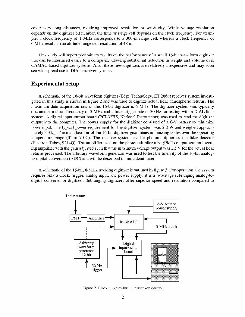
A schematic of the 16-bit waveform digitizer (Edge Technology, ET 2668) receiver system investi-
gated in this study is shown in figure 2 and was used to digitize actual lidar atmospheric returns. The
maximum data acquisition rate of this 16-bit digitizer is 6 MHz. The digitizer system was typically
operated at a clock frequency of 5 MHz and a laser trigger rate of 30 Hz for testing with a DIAL lidar
system. A digital input-output board (PCI-32HS, National Instruments) was used to read the digitizer
output into the computer. The power supply for the digitizer consisted of a 6-V battery to minimize
noise input. The typical power requirement for the digitizer system was 2.8 W and weighed approxi-
mately 2.3 kg. The manufacturer of the 16-bit digitizer guarantees no missing codes over the operating
temperature range (0 ° to 70°C). The receiver system used a photomultiplier as the lidar detector
(Electron Tubes, 9214Q). The amplifier used on the photomultiplier tube (PMT) output was an invert-
ing amplifier with the gain adjusted such that the maximum voltage output was 1.5 V for the actual lidar
returns processed. The arbitrary waveform generator was used to test the linearity of the 16-bit analog-
to-digital conversion (ADC) and will be described in more detail later.
A schematic of the 16-bit, 6-MHz tracking digitizer is outlined in figure 3. For operation, the system
requires only a clock, trigger, analog input, and power supply; it is a two-stage subranging analog-to-
digital converter or digitizer. Subranging digitizers offer superior speed and resolution compared to
Lidar return
_ _Am_Pji_fi]i _ __
I
I
I
I
Arbitrarywave formgenerator,
12 bit
_ 30-Hz
trigger
16-bit ADC
Digitalinput/output
board
6-V batterypower supply
-" I5-MHz clock
I
Figure 2. Block diagram for lidar receiver system.

IReference . .
Offset[ Sig_nal[Inhigh_ conditioningL_A 8-bit [ [ [Inlow-_ sampleand_ flashADC[ [ , "-
] hold • [t'_ _, __ ] 18-bit
Gain [ _ Q_)2 r ---_ [ linear ADC[/
_ - ' fl_hADC T
Clock---_ Timing ]
msb B 1
B2--B3--B4--B5--B6--
B8 B7--
B9
B10--Bll --B12--
B13--B14--B15--
B16--
Latch
mm
Latch
B1
To PCI board
B8
B9
To PCI board
Figure 3. Block diagram of 16-bit digitizer architecture; Y,refers to sum operation.
successive-approximation converters, which have an upper limit conversion speed of approximately
1 ps for 12 bits (ref. 1). The 16-bit subranging digitizer system used in this study works by switching the
sample and hold (S/H) circuit into a hold mode and quantizing the input signal with a flash converter.
Flash converters consist of comparators and logic gates, which quantize the input signal; they are lim-
ited in the number of bits because the number of comparators required increases exponentially with the
bit resolution (refs. 2 and 3). In this system, the use of two flash converters (10 bit and 8 bit), rather than
one, enhances the speed of the digitizer because fewer switching mechanisms are required. The second
flash converter, which receives input from the digital-to-analog converter (D/A), quantizes a difference
signal that is sent to the digital correction logic to generate the final output. The difference signal is pro-
duced by subtracting the output of the D/A from the signal initially sampled by the S/H circuit. The D/A
converts the digital approximation of the analog signal generated by the first flash converter back into
an analog signal that is compared with the analog signal in the S/H circuit. Thus, the output of the first
flash converter is corrected by a feedback into the D/A and a comparison is made with the initial input
signal in the S/H circuit. Note that the second flash converter has some overlapping bits with the first
flash converter, which functions as the error check. Also, the 8-bit flash converter completes the 16-bit
conversion because the first flash converter is only 10 bits.
The flow of data from the 16-bit digitizer is regulated by data latches that capture the data (i.e., the
data are valid) at specific time intervals relative to the timing of the digitizer. A schematic of the digi-
tizer timing is shown in figure 4. The clock line initiates the conversion process, and its input pulse must
remain high for a minimum of 10 ns. The clock sets the sample and hold amplifier in the hold mode and
the sample line low for 7 ns. After a delay of 60 ns, the sample line triggers the transfer line into a high
state. Data N - 1 is valid 30 ns after the start pulse and while the transfer line is high. The transfer line is
not used in the setup of the 16-bit digitizer; instead, the clock trigger sets the data latches and starts the
read function on the personal computer interface (PCI) board. Thus, the data read is one cycle behind
the conversion process. This clock was 5 MHz, which typically is used for ozone lidar measurements.
The PCI board receives a 30-Hz laser trigger pulse, which is synchronized with the 5-MHz clock. The
30-Hz trigger (50 Hz was also successfully implemented), in effect, activates the PCI board, which then
reads data at the rate of the external clock (5 MHz). The 30-Hz input is the trigger used to fire the laser
for ozone lidar measurements. The software that controls the PCI board is written in National Instru-
ments LabVIEW. Data are plotted on the display in real time, relative to the 30-Hz trigger. The operator
inputs the number of laser returns to store and average. The analog digitizer input can range from
+1.5 V to -1.5 V, but the software is written to use only positive voltages.
10 ns minr_l_ r_l _ 200 ns _]
Clock _-_
Data N + 3 sample Data N + 4 sample
Sample
-_-- 90 ns --
Transfer ,
Data
_DataN-lvalidX Notvalid x DataNvalid X__
Figure 4. Timing diagram for 16-bit digitizer.
Ground-based ozone DIAL measurements were made by using the existing Nd-YAG pumped dye
laser system (ref. 2). Briefly, this system consists of two Nd-YAG lasers, one for the DIAL "on-line"
and one for the "off-line" wavelengths. Each Nd-YAG is doubled and then pumps a dye laser, which in
turn is doubled into the ultraviolet. These pulses are then transmitted into the atmosphere.
The atmospheric scattered laser light is collected by a 30-cm diameter telescope. Light from this
telescope is passed through a 300-nm narrowband filter and then focused onto a PMT optical detector.
The PMT was usually gated on after the laser fired, and the gate "on" time was 300 gs for the on-line
return, followed by 300 gs for the off-line return.
Results and Discussion
The 16-bit digitizer will be characterized based on its noise output and then compared to the noise
level of the current CAMAC 12-bit digitizer. The digitizer will also be characterized for linearity by
using an arbitrary waveform generator, as shown in figure 2. Finally, the results of actual ozone DIAL
atmosphere returns with the "on" and "off" wavelengths (set to the same wavelength) will be presented.
The results of actual ozone DIAL atmosphere returns with the on and off wavelengths (set to different
wavelengths) will also be presented to produce an actual ozone profile.
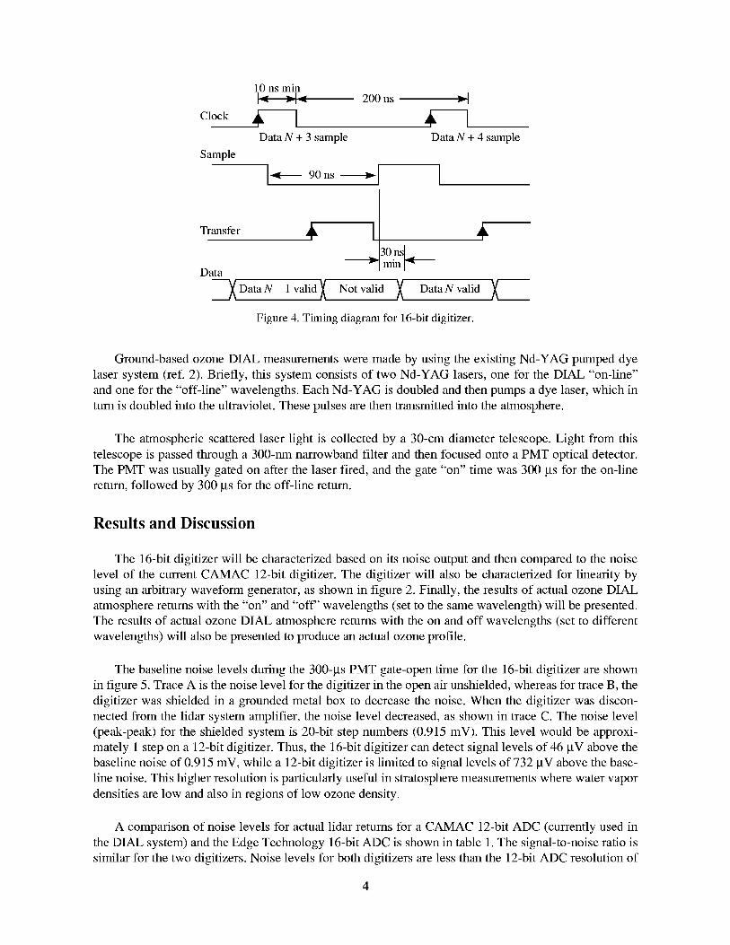
The baseline noise levels during the 300-gs PMT gate-open time for the 16-bit digitizer are shown
in figure 5. Trace A is the noise level for the digitizer in the open air unshielded, whereas for trace B, the
digitizer was shielded in a grounded metal box to decrease the noise. When the digitizer was discon-
nected from the lidar system amplifier, the noise level decreased, as shown in trace C. The noise level
(peak-peak) for the shielded system is 20-bit step numbers (0.915 mV). This level would be approxi-
mately 1 step on a 12-bit digitizer. Thus, the 16-bit digitizer can detect signal levels of 46 btV above the
baseline noise of 0.915 mV, while a 12-bit digitizer is limited to signal levels of 732 btV above the base-
line noise. This higher resolution is particularly useful in stratosphere measurements where water vapor
densities are low and also in regions of low ozone density.
A comparison of noise levels for actual lidar returns for a CAMAC 12-bit ADC (currently used in
the DIAL system) and the Edge Technology 16-bit ADC is shown in table 1. The signal-to-noise ratio is
similar for the two digitizers. Noise levels for both digitizers are less than the 12-bit ADC resolution of
120
110
100
9O
8O
7O
60
5O
4O
30
200 20 40 60 80 100 120 140 160 180 200 220 240 260 280 300
Time,ps
A
B
C
Figure5.Lidarsystemnoisetracers:A, totalnoisewithopen,unshieldeddigitizer;B,totalnoisewithdigitizersshieldedinmetalbox;andC,digitizerdisconnectedfromlidarsysteminput.
0.73mV/step.Thenoiselevelwas the standarddeviationof the baselinefor five measurementsobtainedfromanactuallidarsystem.Thesignal-to-noiseratiowascalculatedby averagingfive actuallidarreturnsanddividingbythestandarddeviation.
Table1.ComparisonofNoiseLevelsforActualLidarReturnsfor12-Bitand16-BitADC
Lidarreturns Signal-to-noiseratio NoiselevelCurrent12-bitADC.......... 95(off-line) 0.244mV(off-line)
230(on-line) 0.244mV(on-line)New16-bitADC.......... 125(off-line) 0.146mV(off-line)
360(on-line) 0.146mV(on-line)
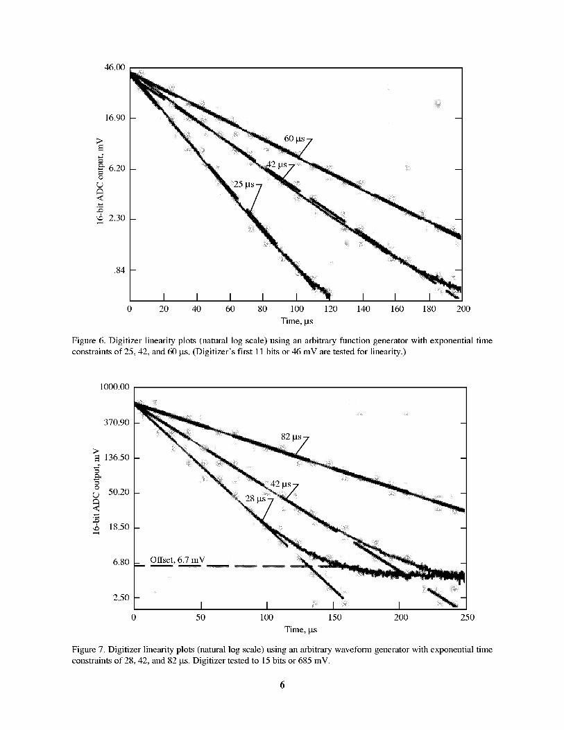
An exponentialoutputfromanarbitraryfunctiongeneratorwasinputto the 16-bitdigitizerandusedtotestthelinearityof the16-bitdigitizer.Plotsof 16-bitdigitizeroutput(mV)versustime(figs.6and7) arelinearfor exponentialfunctionswithgeneratortimeconstantsof 25,28,42,60,and82Bs.Specifically,figure6displaysthelinearityof thefirst 11bitsor46mVof the16-bitdigitizer.Figure7teststhelinearityof the16-bitdigitizerup to 15bitsor 685mV. It isapparentthatthe16-bitdigitizerofferssufficientlinearityforthefull rangeof bitsfor theinputvoltagesbetween0and+1.5V. Digitizernonlinearityisconsideredtheprimarysourceof errorin DIALmeasurements(ref.3).
46.00
16.90
>
6.20O
r,...)
<
2.30
.84
0 20 40 60 80 100 120 140 160 180 200
Time, ps
Figure 6. Digitizer linearity plots (natural log scale) using an arbitrary function generator with exponential time
constraints of 25, 42, and 60 ps. (Digitizer's first 11 bits or 46 mV are tested for linearity.)
1000.00 . I
370.90
>136.50
O
r,.) 50.20
<
18.50
6.80
2.50
Offset. 6.7 mV
82 ps
m
I I I I0 50 100 150 200 250
Time, ps
Figure 7. Digitizer linearity plots (natural log scale) using an arbitrary waveform generator with exponential time
constraints of 28, 42, and 82 ps. Digitizer tested to 15 bits or 685 mV.
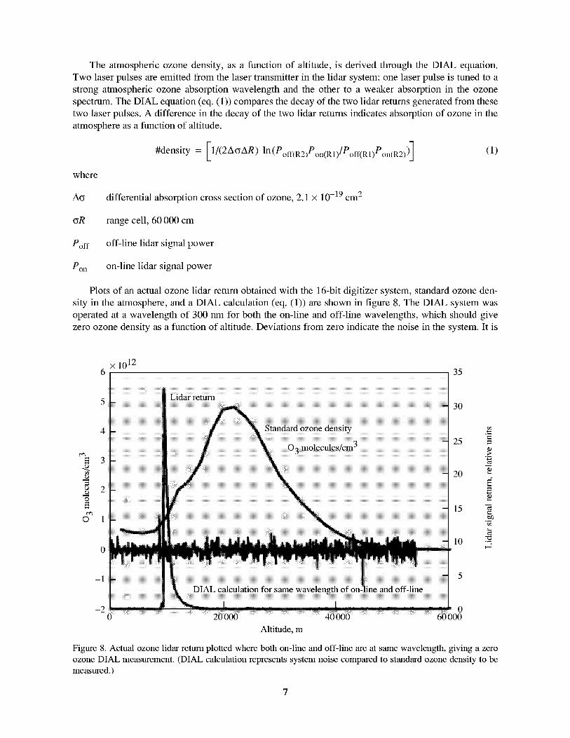
Theatmosphericozonedensity,asafunctionof altitude,is derivedthroughtheDIAL equation.Twolaserpulsesareemittedfromthelasertransmitterin thelidarsystem;onelaserpulseis tunedto astrongatmosphericozoneabsorptionwavelengthandtheotherto a weakerabsorptionin theozonespectrum.TheDIAL equation(eq.(1))comparesthedecayofthetwolidarreturnsgeneratedfromthesetwolaserpulses.A differencein thedecayof thetwolidarreturnsindicatesabsorptionof ozonein theatmosphereasafunctionof altitude.
#density= [1/(2A(_AR)ln(Poff(R2)Pon(R1)/Poff(R1)Pon(R2))] (1)
where
Acy differential absorption cross section of ozone, 2.1 × 10 -19 cm 2
cyR range cell, 60 000 cm
Poff off-line lidar signal power
Pon on-line lidar signal power
Plots of an actual ozone lidar return obtained with the 16-bit digitizer system, standard ozone den-
sity in the atmosphere, and a DIAL calculation (eq. (1)) are shown in figure 8. The DIAL system was
operated at a wavelength of 300 rim for both the on-line and off-line wavelengths, which should give
zero ozone density as a function of altitude. Deviations from zero indicate the noise in the system. It is
x 10126 35
0"3
3
o 20
¢'¢3© 1
3O
25
2O
15
10
e_
-1
-2 00 20 000 40 000 60 000
Altitude, m
Figure 8. Actual ozone lidar return plotted where both on-line and off-line are at same wavelength, giving a zero
ozone DIAL measurement. (DIAL calculation represents system noise compared to standard ozone density to be
measured.)
×10123.0
2.5
2.0o'1
8
1.5O
o'1
o1.0
010 15 20 25 30 35 40
Time, gs
(a) DIAL calculation for one trace, no averaging.
45 50
3.0
2.5
m 2.0
8
8 1.5O
o'1
o1.0
× 1012
iiiiiiiiiiiiiiiiiiiiiiiiiiiiiiiiii ii!i
.5
I I I I0 10 20 30 40 50
Time, gs
(b) DIAL calculation for 5000 traces, averaged.
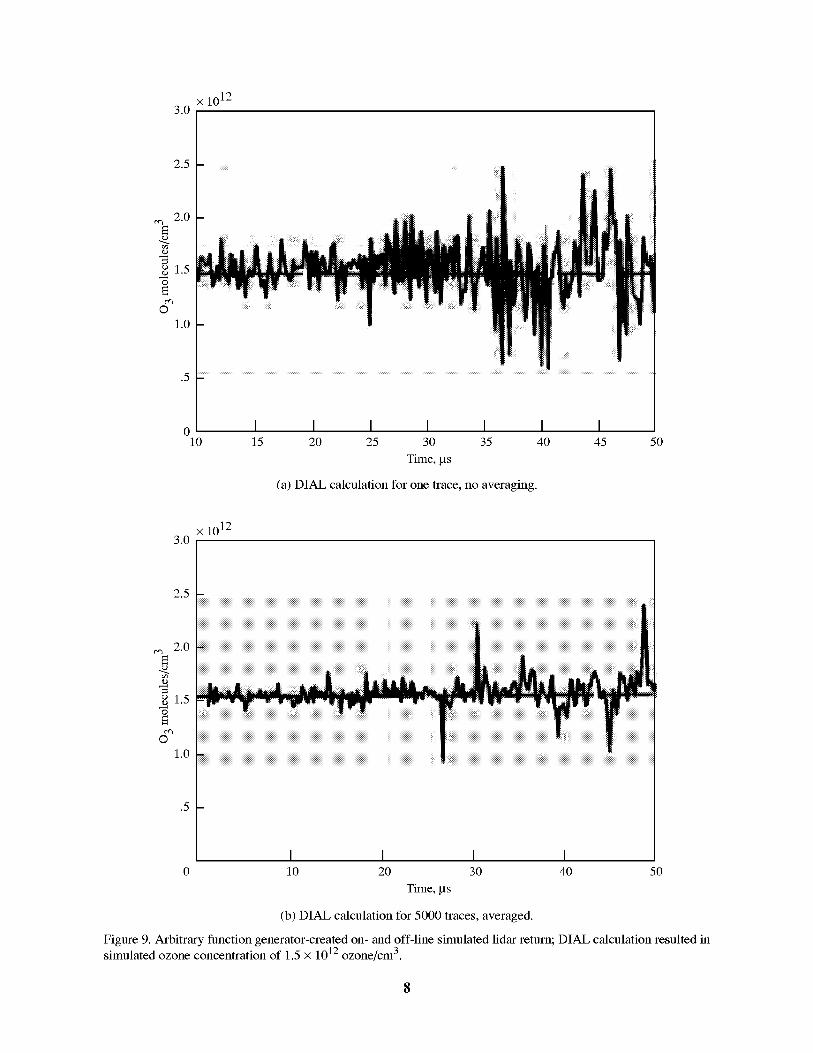
Figure 9. Arbitrary function generator-created on- and off-line simulated lidar return; DIAL calculation resulted insimulated ozone concentration of 1.5 x 10¹² ozone/cm 3.

shownin figure8 thatthe digitizerandsystemnoisearesufficientlylow to resolvethe expectedstratosphericozonedensitythatisshownasthestandardozonedensitycurve.LargenoisespikesappearatthetimethePMTgateopensandcloses.
TheDIAL calculationalsowasperformedby usingLabVIEWprogramming.TheadvantageofusingLabVIEWisthattheDIAL calculationcouldbeincorporatedintothemaindataacquisitionpro-gramandthusbedeterminedin nearrealtimeaftertheacquisitionof theon-lineandoff-line lidarreturns.
TheDIAL calculationshouldbenonzeroif thetwo pulsesfrom thelaserareat differentwave-lengths.Anarbitraryfunctiongenerator(fig.2)wasusedtoproducetwoexponentialfunctionswithdif-ferenttimeconstants,whichsimulatedon-lineandoff-linelidarreturns.Thedecayfor theon-lineandoff-linelidarreturnsis notthesame,whichsimulatesozoneabsorbance.TheDIAL equationexploitsthisdifference,producinganonzerostraightlinecorrespondingto thedifferencesin thetimeconstantsorozonedensity.Discrepanciesin thelinearecausedbynoisein theinstrumentalsystem.
Figure9(a)displaystheDIAL calculationsfor twodifferentexponentialdecaysproducedby thearbitraryfunctiongenerator,withtimeconstantsof 37bts (on-line) and 50 bts (off-line). The calculated
simulated ozone density is 1.5 x 10¹² molecules/cm 3, which is indicated with a dashed line in figures 9
and 10. This ozone density was estimated to be the center of the traces in figures 9 and 10. These data
agree with results published by Langford for a comparable 12-bit digitizer system (ref. 3). Averaging
5000 traces (fig. 9(b)) improves the signal-to-noise ratio, which indicates that the large fluctuations are
caused by random noise in the signal rather than by nonlinearities in the digitizer output. Figure 10
× 10121.0
1.8
1.6
0
ml.40
1.2
1.0
!iiiijiiiiiijiiiiiiijiiiiij]Minimum detectable ozone concentration .63 × 1012
0 10 20 30 40 50
Time, ps
Figure 10. Assuming a signal-to-noise ratio of 2, the minimum detectable ozone concentration of0.63 × 1012 ozone/cm 3 detected by using figure 9 configuration; 5000 traces, averaged.
x 10183
0%
ON
©
_t
F Langley ozone DIAL•
.5
02.0 2.5 3.0 3.5 4.0 4.5 5.0 5.5 6.0 6.5
Height, km
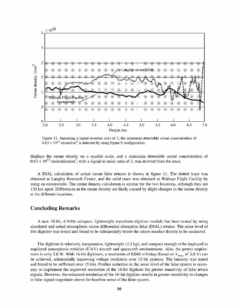
Figure 11. Assuming a signal-to-noise ratio of 2, the minimum detectable ozone concentration of
0.63 x 10¹² ozone/cm 3 is detected by using figure 9 configuration.
7.0
displays the ozone density on a smaller scale, and a minimum detectable ozone concentration of
0.63 x 10¹² molecules/cm 3, with a signal-to-noise ratio of 2, was derived from the trace.
A DIAL calculation of actual ozone lidar returns is shown in figure 11. The dotted trace was
obtained at Langley Research Center, and the solid trace was obtained at Wallops Flight Facility by
using an ozonesonde. The ozone density calculation is similar for the two locations, although they are
130 km apart. Differences in the ozone density are likely caused by slight changes in the ozone density
at the different locations.
Concluding Remarks
A new 16-bit, 6-MHz compact, lightweight waveform digitizer module has been tested by using
simulated and actual atmospheric ozone differential absorption lidar (DIAL) returns. The noise level of
this digitizer was tested and found to be substantially below the ozone number density to be measured.
The digitizer is relatively inexpensive, lightweight (2.3 kg), and compact enough to be deployed in
unpiloted atmospheric vehicles (UAV) aircraft and spacecraft environments. Also, the power require-
ment is only 2.8 W. With 16-bit digitizers, a resolution of 0.046 mV/step (based on Vma x of 3.0 V) can
be achieved, substantially improving voltage resolution over 12-bit systems. The linearity was tested
and found to be sufficient over 15 bits. Further reduction in the noise level of the lidar system is neces-
sary to implement the improved resolution of the 16-bit digitizer for greater sensitivity of lidar return
signals. However, the enhanced resolution of the 16-bit digitizer results in greater sensitivity to changes
in lidar signal magnitude above the baseline noise of the lidar system.
10

References
1. Ushani, Ray K.: Designers' Guide to Subranging ADCs--Part 1. Electron. Des. News, vol. 36, no. 8, 1991,
pp. 139-142.
2. Browell, E. V.: Airborne Lidar Measurements. Rev. Laser Eng., vol. 23, no. 2, 1995, pp. 135-141.
3. Langford, Andrew O.: Identification and Correction of Analog-to-Digital-Converter Nonlinearities and
Their Implications for Differential Absorption Lidar Measurements. Appl. Opt., vol. 34, no. 36, 1995,
pp. 8330-8340.
11
Form ApprovedREPORT DOCUMENTATION PAGE OMB No. 0704-0188
Public reporting burden for this collection of information is estimated to average 1 hour per response, including the time for reviewing instructions, searching existing data sources,gathering and maintaining the data needed, and completing and reviewing the collection of information. Send comments regarding this burden estimate or any other aspect of thiscollection of information, including suggestions for reducing this burden, to Washington Headquarters Services, Directorate for Information Operations and Reports, 1215 JeffersonDavis Highway, Suite 1204, Arlington, VA 22202-4302, and to the Office of Management and Budget, Paperwork Reduction Project (0704-0188), Washington, DC 20503.
1. AGENCY USE ONLY (Leave blank 12. REPORT DATE 3. REPORTTYPE AND DATES COVERED
I February 2000 Technical Memorandum4. TITLE AND SUBTITLE 5. FUNDING NUMBERS
Characterization of a 16-Bit Digitizer for Lidar Data Acquisition
6. AUTHOR(S)
Cynthia K. Williamson and Russell J. De Young
7. PERFORMING ORGANIZATION NAME(S) AND ADDRESS(ES)
NASA Langley Research CenterHampton, VA 23681-2199
9. SPONSORING/MONITORING AGENCY NAME(S) AND ADDRESS(ES)
National Aeronautics and Space AdministrationWashington, DC 20546-0001
WU 274-00-99-24
8. PERFORMING ORGANIZATION
REPORT NUMBER
L-17888
10. SPONSORING/MONITORING
AGENCY REPORT NUMBER
NASA/TM-2000-209860
11. SUPPLEMENTARY NOTES
12a. DISTRIBUTION/AVAILABILITY STATEMENT
Unclassified-Unlimited
Subject Category 33 Distribution: StandardAvailability: NASA CASI (301) 621-0390
12b. DISTRIBUTION CODE
13. ABSTRACT (Maximum 200 words)
A 6-MHz 16-bit waveform digitizer was evaluated for use in atmospheric differential absorption lidar (DIAL) mea-surements of ozone. The digitizer noise characteristics were evaluated, and actual ozone DIAL atmospheric returnswere digitized. This digitizer could replace computer-automated measurement and control (CAMAC)-basedcommercial digitizers and improve voltage accuracy.
14. SUBJECT TERMS
Waveform digitizer; Lidar; Differential absorption lidar (DIAL)15. NUMBER OF PAGES
1716. PRICE CODE
A03
17, SECURITY CLASSIFICATION 18, SECURITY CLASSIFICATION 19, SECURITY CLASSIFICATION 20, LIMITATION
OF REPORT OF THIS PAGE OF ABSTRACT OF ABSTRACT
Unclassified Unclassified Unclassified UL
NSN 7540-01-280-5500 Standard Form 298 (Rev. 2-89)Prescribed by ANSI Std. Z39-18298-102