Embed Size (px)
Citation preview
Chapter 3Materials & Methods 115
b) Tcl::resultf(const char baton result) set the value of tcl result(). After location the
value of tcl result() in C++, NS2 may go back to OTcl with a sure return value
(e.g., TCL_OK, TCL_ERROR). following returning to OTcl, the predictor reads the
value of tcl result() for a certain reason (e.g., setting the delay value or reporting
mistake).
likewise, after execute an OTcl statement, the implementation result is stored in
the changeable tcl result(). role Tcl::result(void) in the compile hierarchy returns the
rate stored in tcl result() by the judge.
3.11.4 Reporting Error and Quitting the Program
Class Tcl supply meaning “error()” to exit the programing a uniform way. This
meaning simply prints a twine stored in “str” and tcl result() to the display, and exits
with code 1.
Tcl::mistake (const char pointer str)
The dissimilarity among Tcl::error(str) and go back TCL_ERROR is as follows. Function
Tcl::error(str) simply prints out the error communication and exits. When returning
TCL_ERROR, NS2 traps the mistake, which may happen in more than one point. In the
end, the user may use the attentive errors to get well from the error, to place the error, or
to print all error messages in the fault heap.
3.11.5 Retrieve the Reference to TclObjects
Recall that an interpreted object always has a shadow compiled object. In some
cases, we may need to obtain a shadow compiled object which corresponds to an
interpreted object.
NS2 creates the association between objects in two hierarchies by means of a hash
table. Class Tcl provides the following functions to enter, delete, and retrieve an entry
to/from the hash table.
Chapter 3Materials & Methods 116
• Tcl::enter(TclObject pointer o): inserts the object pointer o to the hash table, and
associates pointer o to the OTcl name string stored in a protected variable name. This
function is invoked by function TclClass:create_shadow(), when an object is created.
• Tcl::delete(TclObject pointer o): deletes the entry associated with TclObject pointer o
from the hash table. This function is invoked by function TclClass:delete_shadow(),
when an object is destroyed.
• Tcl::lookup(char pointer str): returns the TclObject whose name is “str”.
3.12 Class InstVar
Group InstVar acts as a glue which binds a associate variable of a C++ class to an
instproc of an OTcl class. When a C++ changeable is bound to an OTcl instvar, any vary
in the C++ variable or the OTcl instvar will consequence in an routine update the OTcl
instvar or the C++ variable, in that order. NS2 supports variable compulsory with five
next NS2 information type:
1. Real
2. Integer
3. Bandwidth
4. Time
5. Boolean.
These five facts types are neither a C++ information type nor an OTcl data type.
They are defined here to make easy NS2 value assignment. As shown in Table 3.3, these
statistics types are distinct in the C++ classes InstVarReal, InstVarInt, InstVarBandwidth,
InstVarTime, and InstVarBool in that order, which get from class InstVar. surrounded by
these five data types, real, bandwidth, and time data types create use of a twice C++ data
type, while figure and boolean use int and bool C++ information types, in that order.
3.12.1 Real and Integer Variables
These two NS2 data types are specified as real-valued and integer-valued,
respectively. Optionally, we can also use “e<x>” as “×10<x>”, where <x> denotes the
value stored in the variable x.
Chapter 3Materials & Methods 117
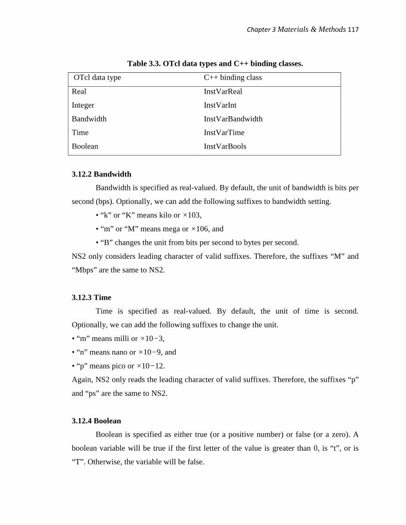
Table 3.3. OTcl data types and C++ binding classes.
OTcl data type C++ binding class
Real InstVarReal
Integer InstVarInt
Bandwidth InstVarBandwidth
Time InstVarTime
Boolean InstVarBools
3.12.2 Bandwidth
Bandwidth is specified as real-valued. By default, the unit of bandwidth is bits per
second (bps). Optionally, we can add the following suffixes to bandwidth setting.
• “k” or “K” means kilo or ×103,
• “m” or “M” means mega or ×106, and
• “B” changes the unit from bits per second to bytes per second.
NS2 only considers leading character of valid suffixes. Therefore, the suffixes “M” and
“Mbps” are the same to NS2.
3.12.3 Time
Time is specified as real-valued. By default, the unit of time is second.
Optionally, we can add the following suffixes to change the unit.
• “m” means milli or ×10−3,
• “n” means nano or ×10−9, and
• “p” means pico or ×10−12.
Again, NS2 only reads the leading character of valid suffixes. Therefore, the suffixes “p”
and “ps” are the same to NS2.
3.12.4 Boolean
Boolean is specified as either true (or a positive number) or false (or a zero). A
boolean variable will be true if the first letter of the value is greater than 0, is “t”, or is
“T”. Otherwise, the variable will be false.

Chapter 3Materials & Methods 118
After assigning a value to an OTcl variable, NS2 converts the thread value to the
parallel type in C++. Except for boolean, NS2 converts the thread to either two times or
int. through the exchange, valid suffixes are and converted. For Boolean information
type, NS2 regain the first quality in the string and hurl away all extra fonts. If the
retrieved quality is an figure, NS2 will do not anything. If the retrieved nature is a non-
integer, NS2 will change the nature to one if it is “t” or “T” and to nothing or else. After
convert the string to a one-digit figure, NS2 casts the rehabilitated integer to boolean and
inform the bound compiled erratic.
3.13 Class TclObject
Class TclObject provides an instruction to create a compiled shadow object, when
an interpreted object is created. The C++ class TclObject is mapped to the OTcl class
SplitObject. These two classes are the base classes from which all classes (excluding the
standalone classes) in their hierarchies develop. When an object is instantiated from the
OTcl domain, the constructor of class SplitObject is invoked to initialize the object.
3.13.1 Reference to a TclObject
OTcl and C++ spend different way to access their objects. As a compiler, C++
openly accesses the recall space allocated for a sure thing. As an predictor, OTcl does not
in a straight line admission the memory. quite, it uses a cord as a position to the thing.
Table 3.4 shows examples of the position worth of C++ and OTcl stuff.
Table 3.4. Reference to TclObjects.
Domain Variable name Example
C++ cpp_object 0xd76b9c0
OTcl otl_object _o50
We can see the format of a value stored in an OTcl object by running the following
codes:
set ns [new Simulator]
Chapter 3Materials & Methods 119
set tcp [new Agent/TCP]
3.13.2 Creating and Destroying a Shadow TclObject
In most cases, substance are created and destroyed in the OTcl domain, or more
precisely in a Tcl simulation script. Again, the OTcl commands produce and destroy can
be used to create and destroy, respectively, a unconnected OTcl object. However, these
commands are rarely used in NS2, since they do not create the darkness compiled object.
In NS2, the global procedures new() and delete() are used to create and delete, in that
order, an OTcl object as well as a shadow compiled object. For instance to create an OTcl
Agent/TCP object, we can execute “new Agent/TCP” from a Tcl Simulation Script. In
the interpreted pecking order, class Agent/TCP derives from class Agent, which get from
class SplitObject. In the compiled pecking order, these three classes write to class
TcpAgent, Agent, and TclObject, in that order.
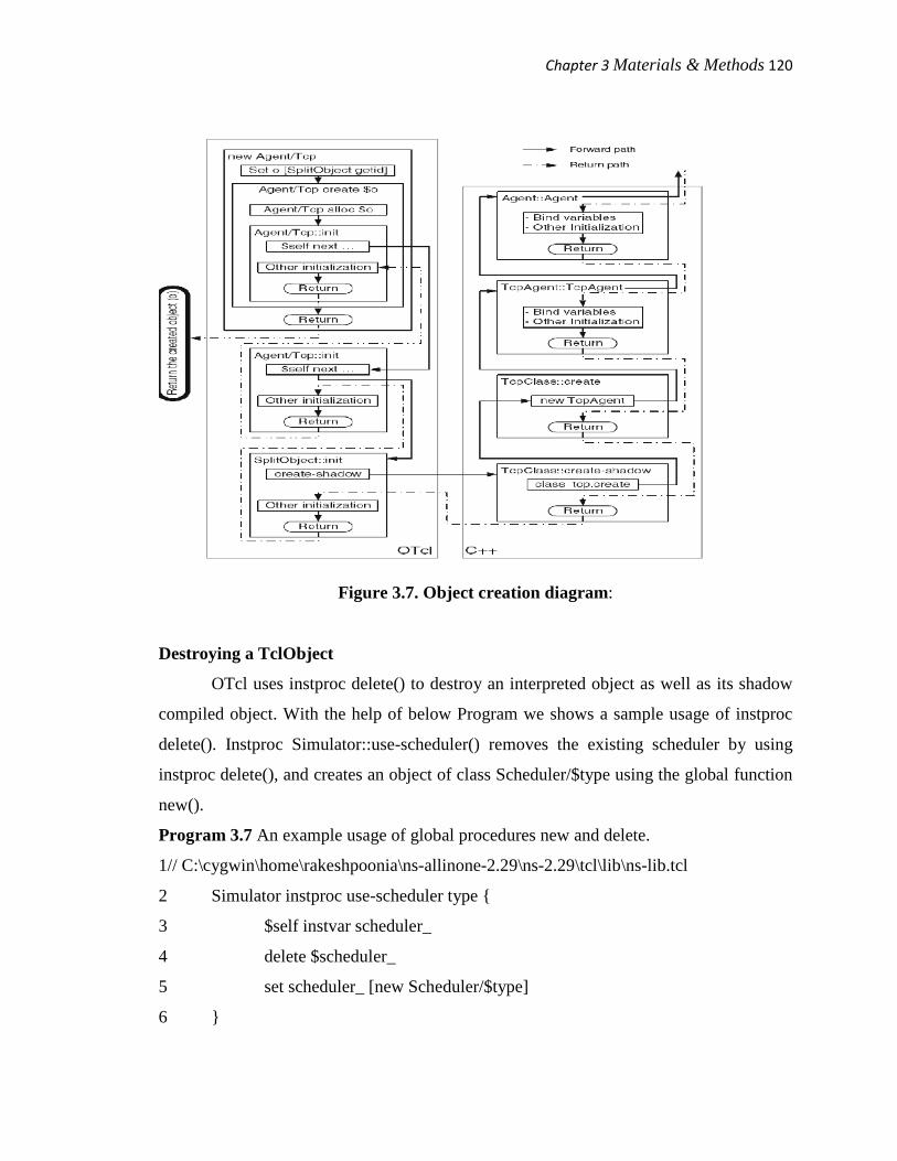
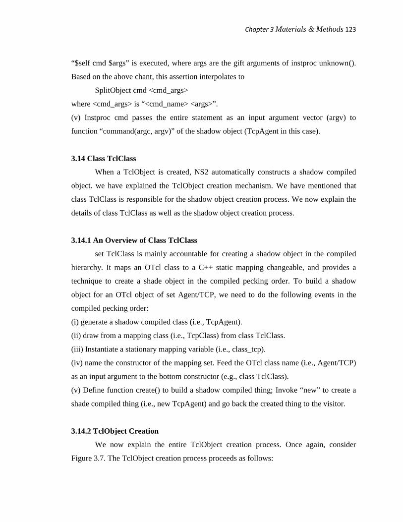
Figure 3.7 shows the formation process of an object (o) of class Agent/TCP. once
more, the first step is to get back a reference string by invoking instproc getid purpose of
class SplitObject. The after that step is to invoke instproc init job up the ladder. On the
top level, class SplitObject invokes authority create-shadow to create a shadow compiled
thing.
After recurring from instproc create-shadow, the procedure performs the rest of
initialization and moves down the interpreted pecking order until it reaches class
Agent/TCP. Then, it returns to function create() and new(), in that order, where the
reference string matching to the created thing “o” is returned to the caller (of function
new()). Note that the on top of procedures are used to create an interpreted TclObject
which is linked to the compiled hierarchy. Standalone C++ or OTcl objects do not need
any shadow entity, and do not have to go from side to side the above procedures. They
can be construct in a usual mode.
Chapter 3Materials & Methods 120
Figure 3.7. Object creation diagram:
Destroying a TclObject
OTcl uses instproc delete() to destroy an interpreted object as well as its shadow
compiled object. With the help of below Program we shows a sample usage of instproc
delete(). Instproc Simulator::use-scheduler() removes the existing scheduler by using
instproc delete(), and creates an object of class Scheduler/$type using the global function
new().
Program 3.7 An example usage of global procedures new and delete.
1// C:\cygwin\home\rakeshpoonia\ns-allinone-2.29\ns-2.29\tcl\lib\ns-lib.tcl
2 Simulator instproc use-scheduler type {
3 $self instvar scheduler_
4 delete $scheduler_
5 set scheduler_ [new Scheduler/$type]
6 }

Chapter 3Materials & Methods 121
3.13.3 Binding Variables in the Compiled and Interpreted Hierarchies
In universal both interpret and compiled objects have their own class variables,
and they are not allowed to directly right of entry one another’s class variables. NS2,
therefore, provides a mechanism which binds class variables in both hierarchies jointly.
After the binding, a change in a class variable in one hierarchy will result in an habitual
change in the bound variable in another hierarchy.
Binding Variables in Both Hierarchies
NS2 binds an interpreted class changeable to a compiled variable during shadow
object construction. More specifically, class TclObject invokes the next functions in the
constructor to bind variables in cooperation hierarchies (see file
C:\cygwin\home\rakeshpoonia\ns-allinone-2.29\tclcl-1.17\tclcl.h).
bind("iname",&cname)
bind_bw("iname",&cname)
bind_time("iname",&cname)
bind_bool("iname",&cname)
anywhere iname and cname are the names of the class variables in the interpreted and
amass hierarchies, in that order. Essentially, the first and second arguments of the on top
of functions are the name filament of the interpreted variable and the address of the
compiled changeable, in that order.
3.13.4 OTcl Commands
An approach to access the interpreted hierarchy from the compiled hierarchy. We
discusses the reverse: a method to access the compiled hierarchy from the interpreted
hierarchy called “command”.
Review of Instance Procedure Invocation Mechanism
An instproc is invoked according to the following syntax:
$obj <instproc> [<args>]
Chapter 3Materials & Methods 122
where the instproc name <instproc> and the input argument <args> are mandatory and
optional, respectively, for such an invocation. The internal mechanism of the above
instproc invocation proceeds as follows:
(i) Look for a matching instproc in the object class. If found, execute the matched
instproc and return. If not, proceed to the next step.
(ii) Look for instproc unknown(). If found, execute unknown() and return. If not, proceed
to the next step. The instproc unknown() is the default instproc which will be invoked if
no matching instproc is found.
(iii) Repeat steps (i) and (ii) for the base class of the object.
(iv) If the top class is reached but neither the input instproc nor the instproc unknown is
found, report an error and exit the program.
OTcl Command Invocation
The grammar of a rule is the same as that of an instproc, i.e.,
$obj <cmd_name> [<args>]
The main dissimilarity is that <instproc> is replaced with <cmd_name>. Since the syntax
for invoking a authority is the same as that for invoking an instproc, OTcl executes the
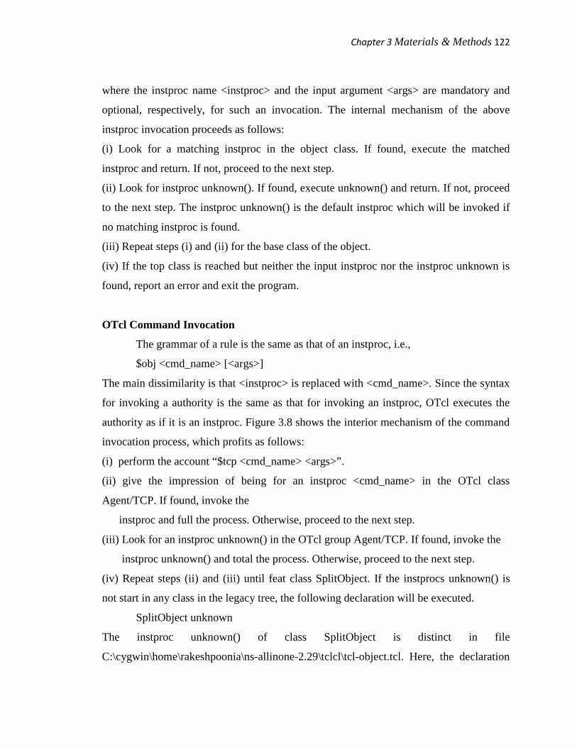
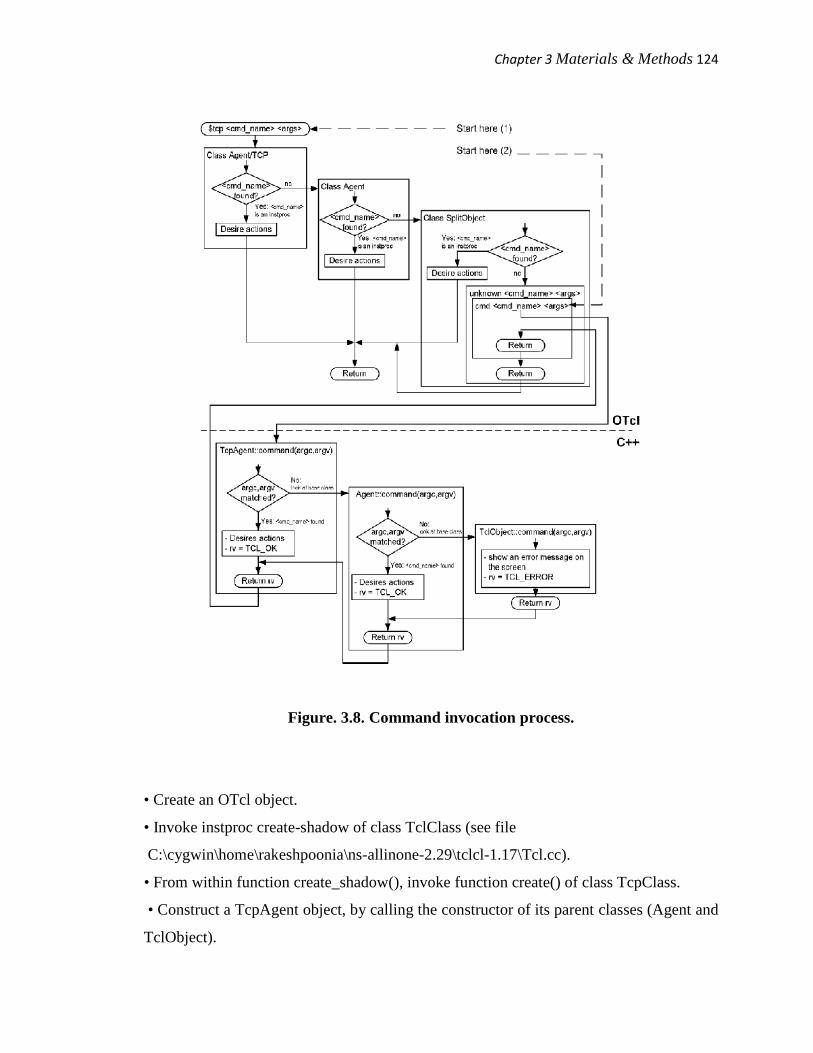
authority as if it is an instproc. Figure 3.8 shows the interior mechanism of the command
invocation process, which profits as follows:
(i) perform the account “$tcp <cmd_name> <args>”.
(ii) give the impression of being for an instproc <cmd_name> in the OTcl class
Agent/TCP. If found, invoke the
instproc and full the process. Otherwise, proceed to the next step.
(iii) Look for an instproc unknown() in the OTcl group Agent/TCP. If found, invoke the
instproc unknown() and total the process. Otherwise, proceed to the next step.
(iv) Repeat steps (ii) and (iii) until feat class SplitObject. If the instprocs unknown() is
not start in any class in the legacy tree, the following declaration will be executed.
SplitObject unknown
The instproc unknown() of class SplitObject is distinct in file
C:\cygwin\home\rakeshpoonia\ns-allinone-2.29\tclcl\tcl-object.tcl. Here, the declaration
Chapter 3Materials & Methods 123
“$self cmd $args” is executed, where args are the gift arguments of instproc unknown().
Based on the above chant, this assertion interpolates to
SplitObject cmd <cmd_args>
where <cmd_args> is “<cmd_name> <args>”.
(v) Instproc cmd passes the entire statement as an input argument vector (argv) to
function “command(argc, argv)” of the shadow object (TcpAgent in this case).
3.14 Class TclClass
When a TclObject is created, NS2 automatically constructs a shadow compiled
object. we have explained the TclObject creation mechanism. We have mentioned that
class TclClass is responsible for the shadow object creation process. We now explain the
details of class TclClass as well as the shadow object creation process.
3.14.1 An Overview of Class TclClass
set TclClass is mainly accountable for creating a shadow object in the compiled
hierarchy. It maps an OTcl class to a C++ static mapping changeable, and provides a
technique to create a shade object in the compiled pecking order. To build a shadow
object for an OTcl object of set Agent/TCP, we need to do the following events in the
compiled pecking order:
(i) generate a shadow compiled class (i.e., TcpAgent).
(ii) draw from a mapping class (i.e., TcpClass) from class TclClass.
(iii) Instantiate a stationary mapping variable (i.e., class_tcp).
(iv) name the constructor of the mapping set. Feed the OTcl class name (i.e., Agent/TCP)
as an input argument to the bottom constructor (e.g., class TclClass).
(v) Define function create() to build a shadow compiled thing; Invoke “new” to create a
shade compiled thing (i.e., new TcpAgent) and go back the created thing to the visitor.
3.14.2 TclObject Creation
We now explain the entire TclObject creation process. Once again, consider
Figure 3.7. The TclObject creation process proceeds as follows:
Chapter 3Materials & Methods 124
Figure. 3.8. Command invocation process.
• Create an OTcl object.
• Invoke instproc create-shadow of class TclClass (see file
C:\cygwin\home\rakeshpoonia\ns-allinone-2.29\tclcl-1.17\Tcl.cc).
• From within function create_shadow(), invoke function create() of class TcpClass.
• Construct a TcpAgent object, by calling the constructor of its parent classes (Agent and
TclObject).
Chapter 3Materials & Methods 125
• Construct Agent object. This includes binding all variables to those in the interpreted
hierarchy.
• Return to class TcpAgent. Construct the TcpAgent object, and bind all variables to
those in the interpreted hierarchy.
• Return the created shadow object to instproc SplitObject::init().
3.14.3 Naming Convention for Class TclClass
The meeting to name a class derived from class TclClass and the matching static
variable are explain now. First, every set derives directly from class TclClass,
irrespective of its class hierarchy. For case in point, class RenoTcpAgent derives from
class TcpAgent. However, their mapping classes RenoTcpClass and TcpClass derive
from set TclClass.
Secondly, the naming convention is very comparable to the C++ variable naming
convention. In most cases, we just name the mapping class by attaching the utterance
Class to the C++ class name. The still mapping variable is named by attaching the
utterance “class_” to the front. Table 3.5 shows few instance of the above naming
meeting.
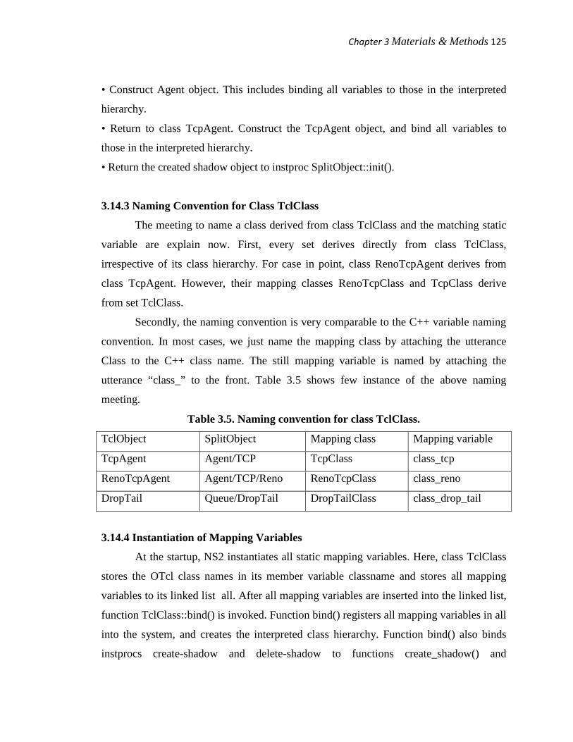
Table 3.5. Naming convention for class TclClass.
TclObject SplitObject Mapping class Mapping variable
TcpAgent Agent/TCP TcpClass class_tcp
RenoTcpAgent Agent/TCP/Reno RenoTcpClass class_reno
DropTail Queue/DropTail DropTailClass class_drop_tail
3.14.4 Instantiation of Mapping Variables
At the startup, NS2 instantiates all static mapping variables. Here, class TclClass
stores the OTcl class names in its member variable classname and stores all mapping
variables to its linked list all. After all mapping variables are inserted into the linked list,
function TclClass::bind() is invoked. Function bind() registers all mapping variables in all
into the system, and creates the interpreted class hierarchy. Function bind() also binds
instprocs create-shadow and delete-shadow to functions create_shadow() and
Chapter 3Materials & Methods 126
delete_shadow() of the mapping classes, respectively. After this point, NS2 recognizes all
OTcl class names.
3.15 Class TclCommand
OTcl control is a method to access the compiled ladder form the interpreted
ladder. The main difference of OTcl authority and TclCommands is as follows. Each
OTcl authority is associated with an OTcl/C++ set and cannot be invoked alone. Each
TclCommand, on the extra hand, is not hop to any class and is obtainable globally. Since
TclCommands infringe the thing leaning idea, it is not sensible to create this kind of
instructions.
3.15.1 Invoking a TclCommand
A TclCommand is appeal to as if it is a global OTcl procedure.
• TclCommand ns-version takes no dispute and returns NS2 version.
• TclCommand ns-random proceeds a random number homogeneously distributed in
[0, 231−1] when no disagreement is specified. If an input disagreement is given, it
will be used to set the seed of the random value producer.
In NS2, a random number is create by picking a number from a progression of pseudo
random numbers. A accidental seed specifies the starting site in the run. By evasion, NS2
always sets chance seed to be 0. The results from manifold simulations would be the
same if not the seeds are set in a different way.
3.15.2 Creating a TclCommand
A TclCommand creation process is similar to those of a TclClass and function
command of a TclObject. A TclCommand is defined in a class derived from class
TclCommand. The name of a Tclcommand is provided as an input argument of class
TclCommand, while the implementation is defined in function. When NS2 starts, it binds
all TclCommand names to function of the corresponding classes.
Chapter 3Materials & Methods 127
3.15.3 Defining Your Own TclCommand
To create a TclCommand, you need to
(i) Derive a TclCommand class directly from class TclCommand,
(ii) Feed the TclCommand name to the constructor of class TclCommand,
(iii) Provide implementation in the function command, and
(iv) Add an object instantiation statement in function init_misc.
Implementation of Discrete-Event Simulation in NS2
NS2 is a discrete-event simulator, where events are associated with actions rather
than time. An happening in a discrete-event simulator consists of execution time, a set of
actions, and a reference to the next event (Figure 3.9). These events connect to every
other and form a chain of events on the reproduction timeline as in Figure 4.1. Unlike a
time-driven simulator, in an event-driven simulator, time flanked by a pair of events does
not need to be steady. When the imitation starts, events in the chain are carry out from
left to right (i.e., chronologically).
3.16 NS2 Simulation Concept
NS2 simulation consists of two main phases.
Phase I: Network pattern Phase In this phase, NS2 constructs a system and sets up an first
chain of events. The initial chain of events consists of events which are scheduled to take
place at certain times. These events are identify at-events. This phase corresponds to each
line in a Tcl imitation script before execute instproc run() of the Simulator object.
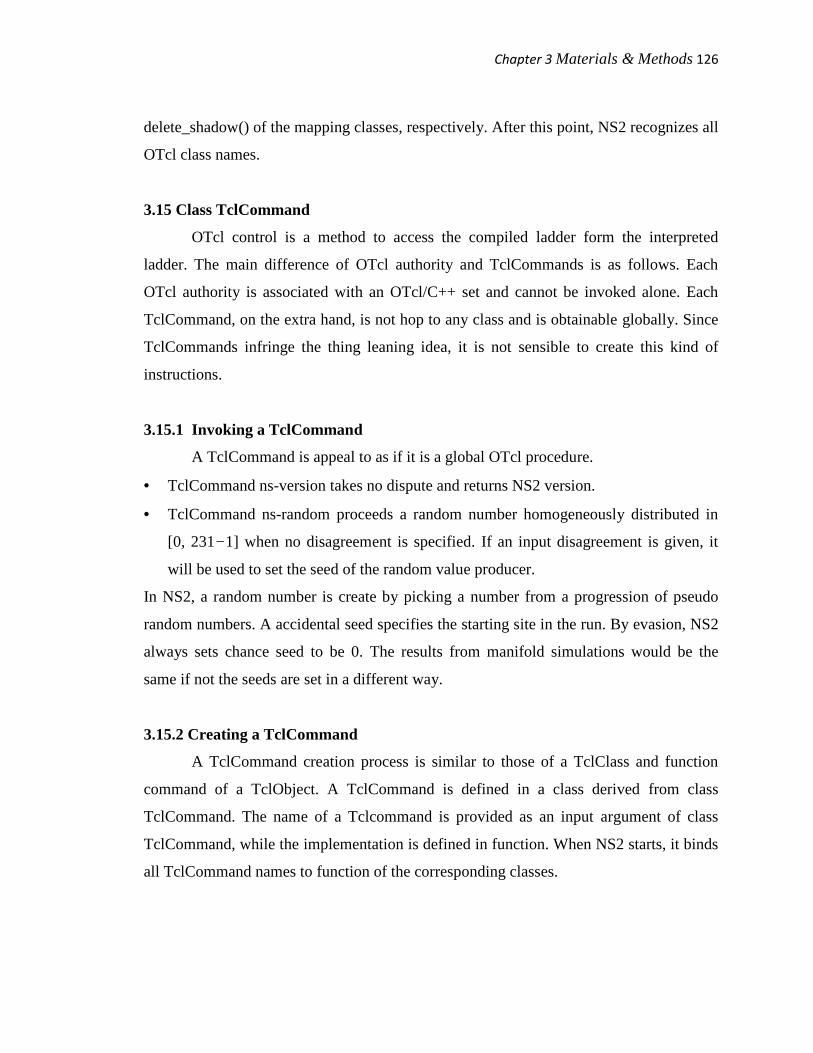
Figure 3.9. A sample chain of events in a discrete-event simulation.
Chapter 3Materials & Methods 128
Each event contains execution time and a reference to the next event. In this figure,
Event1 creates and inserts Event5 after Event2 (the execution time of Event 5 is at 3.7
second).
Phase II: Simulation Phase
This fraction corresponds to a solitary line, which appeal to instproc
Simulator::run(). paradoxically, this single line add to most of the imitation.
In this part phase, NS2 stir along the series of events and executes all event
chronologically. Here, the instproc Simulator::run() starts the imitation by send off the
first event in the sequence of proceedings. In NS2, dispatching an occasion or firing an
event means charming actions matching to that occasion. An action is, for eg.,
preliminary FTP transfer or create one more event and inserting the created occasion into
the sequence of events. In Figure 3.9, at 0.9 s, happening creates Event 5 which will be
dispatch at 3.7 s, and inserts Event 5 after Event 2. After dispatch an event, NS2 moves
down the series and dispatches the after that event. This course repeats until the last event
analogous to instproc halt() of OTcl class Simulator is dispatched, symptomatic of the
end of reproduction.
3.17 Events and Handlers
3.17.1 An Overview of Events and Handlers
As shown in Figure 3.9, an event specifies an action to be taken at a certain time.
In NS2, an event contains a handler which specifies the action, and the firing time or
dispatching time
3.17.2 Class NsObject: A Child Class of Class Handler
Resulting from class Handler, class NsObject is one of the main classes in NS2. It
is a base class for most of the network mechanism. The implementation of function
NsObject::handle(e) . Function NsObject::handle(e) casts an Event object related with the
input pointer (e) to a pack object. Then it feeds the casted thing to function recv(p).
Usually, function recv(p), where p is a pointer to a packet, indicates that an object has
Chapter 3Materials & Methods 129
received a packet p. Unless purpose handle(e) is overridden, purpose handle(e) of an
NsObject simply indicates packet reception.
3.17.3 Classes Packet and AtEvent: Child Classes of Class Event
lessons Packet and AtEvent are among key NS2 classes which obtain from class
Event. These two classes can be located on the chain of events so that their associated
handler will take actions at the firing time. class AtEvent represents events whose action
is the implementation of an OTcl statement. It hold one string variable proc which holds
an OTcl statement string. At the firing time, its associated handler, whose class is
AtHandler, will get back and execute the OTcl string from this changeable. Derivative
from class Handler, class AtHandler specifies the actions to be taken at firing time in its
function grip. The input event into an AtEvent object.
In the OTcl domain, an AtEvent thing is placed in a chain of events at a certain
firing time by instproc of class Simulator. The syntax for the chant is given below:
$ns at <timestamp> <statement>
where ns is the Simulator object, <timestamp> is the dismissal time, and <statement> is
an OTcl statement filament which will be executed when the simulation time is
<timestamp> second. The details of instproc at of an OTcl class Simulator and an OTcl
power at of class Scheduler. The instproc at of set Simulator invokes an OTcl command
at of the Scheduler object.
Authority at of class Scheduler stores the firing time in variable t, then creates an
AtEvent object. The input OTcl command in the changeable proc of the created AtEvent
object. The firing time to the delay time from the current time. lastly, the schedules are
created AtEvent e at delay seconds in future, feeding the address of changeable handle is
an input argument to function schedule().
3.18 The Simulator
OTcl and C++ classes Simulator are the main classes which oversee the entire
simulation. Like the Scheduler object, there can be simply one Simulator object
throughout a simulation. This object will be referred to as the Simulator hereafter. The

Chapter 3Materials & Methods 130
Simulator surround two types of key components: simulation objects and information-
storing objects. While simulation purpose are the key in components which derive the
simulation, as well as the simulator are fashioned during the Network pattern Phase, and
will be used in the Simulation stage.
Information-storing objects hold information which is shared among several
objects. E.g., NS2 needs to be acquainted with all created nodes and links in order to
construct a routing table. These information storing objects are created by a variety of
instprocs during the Network Configuration Phase. In the Simulation time, most objects
access these information-storing objects via its instvar ns, which is the position to the
Simulator.
3.18.1 Main Components of a Simulation
Interperted Hierarchy
Created by various instprocs, the main OTcl simulation components are as
follows:
• The Scheduler created by instproc Simulator::init maintains the chain of events and
executes the events chronologically.
• The null agent (nullAgent created by instproc Simulator::init) provides the common
packet dropping point.
• Node reference Node created by instproc Simulator::node is an associative array whose
elements are the created nodes and indices are node IDs.
• Link reference link created by instprocs simplex-link() or duplexlink() is an associative
array. Associated with an index with format sid:did, each element of link is the created
uni-directional link which carries packet from node sid to node did.
Compiled Hierarchy
In the compiled pecking order, class Simulator also contains variables and
functions Variable instance is a baton to the Simulator. It is a static variable, which
means that there is only one variable instance of class Simulator for the entire imitation.
Variable nodelist is the linked list containing the created nodes. The linked list can have
Chapter 3Materials & Methods 131
upto size elements, while the total number of nodes is nn. Variable rtobject is a pole to a
RouteLogic object, which is responsible for the routing machine.
Job populate_flat_classifiers() pulls out the routing in order stored in variable
rtobject and installs the routing bench in the created nodes and links. Function
add_node() puts the input argument node into the linked list of nodes nodelist. purpose
get_link_head() returns the link head thing of the link with ID nh which attach to a
ParentNode object *node. purpose node_id_by_addr(addr) converts node speak to addr to
node ID. purpose alloc(n) allocates spaces in nodelist which can house up to n nodes, and
clears all mechanism of nodelist to NULL. Function check(n) right away returns if n is
less than size. or else, it will create more space in nodelist, which can house upto n nodes.
Static purpose example() in returns the variable instance which is the baton to the
simulator.
3.18.2 Retrieving the Instance of the Simulator
From the interpreted hierarchy, we can also retrieve the simulator instance by
invoking instproc instance() of class Simulator. This instproc executes the OTcl built-in
command info with an option instances. This execution returns all the instances of a
certain class. Since there is only one Simulator instance, the statement Simulator info
instances returns the Simulator object as required.
3.18.3 Simulator Initialization
Simulator initialization refers to the procedure in the Network Configuration
Phase, which creates the Simulator as well as its mechanism. The Simulator is created by
executing new Simulator. This command call up the constructor i.e., instproc init() of
class Simulator. The constructor first initializes the packet layout in, and invokes instproc
use-scheduler(type) in to specify the type of the Scheduler. By non-payment, the type of
the Scheduler is Calendar. We creates a null manager (nullAgent). Sets the address
format to the default format. Instproc use-scheduler(type) will delete the obtainable
scheduler if it is different from that specified in the input argument type. Then it will
Chapter 3Materials & Methods 132
make a scheduler with type = type, and amass the created Scheduler thing in instvar
scheduler.
3.18.4 Running Simulation
The Simulation Phase starts at the invocation of instproc Simulator::run(). The
instproc Simulator::run() first invokes instproc configure() of class RouteLogic. This
instproc computes the optimal routes and creates the routing table. Finally, The Scheduler
is invoking the OTcl command run() of class Scheduler, which in turn invokes the C++
function run() of class Scheduler. Again, this function executes events in the chain of
events one after another until the Simulator is halted, or until all the events are executed.
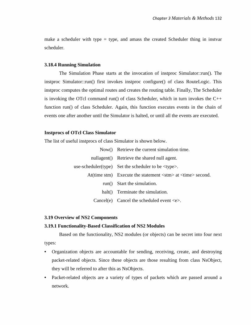
Instprocs of OTcl Class Simulator
The list of useful instprocs of class Simulator is shown below.
Now() Retrieve the current simulation time.
nullagent() Retrieve the shared null agent.
use-scheduler(type) Set the scheduler to be <type>.
At(time stm) Execute the statement <stm> at <time> second.
run() Start the simulation.
halt() Terminate the simulation.
Cancel(e) Cancel the scheduled event <e>.
3.19 Overview of NS2 Components
3.19.1 Functionality-Based Classification of NS2 Modules
Based on the functionality, NS2 modules (or objects) can be secret into four next
types:
• Organization objects are accountable for sending, receiving, create, and destroying
packet-related objects. Since these objects are those resulting from class NsObject,
they will be referred to after this as NsObjects.
• Packet-related objects are a variety of types of packets which are passed around a
network.
Chapter 3Materials & Methods 133
• Simulation-related objects control imitation timing, and oversee the entire simulation.
For instance simulation-related objects are events, trainer, the Scheduler, and the
Simulator.
• Helper objects do not openly contribute in packet forwarding. However, they
implicitly help to complete the simulation. For example, a direction-finding module
calculates routes from a source to a destination, while system address identifies every
of the network objects.
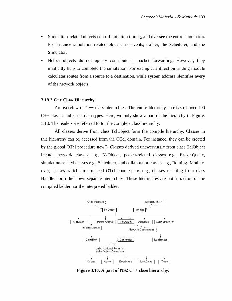
3.19.2 C++ Class Hierarchy
An overview of C++ class hierarchies. The entire hierarchy consists of over 100
C++ classes and struct data types. Here, we only show a part of the hierarchy in Figure.
3.10. The readers are referred to for the complete class hierarchy.
All classes derive from class TclObject form the compile hierarchy. Classes in
this hierarchy can be accessed from the OTcl domain. For instance, they can be created
by the global OTcl procedure new(). Classes derived unswervingly from class TclObject
include network classes e.g., NsObject, packet-related classes e.g., PacketQueue,
simulation-related classes e.g., Scheduler, and collaborator classes e.g., Routing- Module.
over, classes which do not need OTcl counterparts e.g., classes resulting from class
Handler form their own separate hierarchies. These hierarchies are not a fraction of the
compiled ladder nor the interpreted ladder.
Figure 3.10. A part of NS2 C++ class hierarchy.

Chapter 3Materials & Methods 134
Class trainer specifies an action linked with an event. once more, class Handler
contain a pure near function handle(e). consequently, its derived classes are in charge for
providing the execution of function handle(e). For example, role handle(e) of class
NsObject tells the NsObject to receive an incoming packet, while that of set
QueueHandler invokes task resume() of the associated line up purpose.
Resulting in a straight line from class TclObject and Handler, class NsObject is
the template class for all NS2 network objects. It come into OTcl interfaces from class
TclObject and the default action i.e., function handle(e) from class trainer. In addition, it
defines a packet reception stencil, and forces all its derived classes to provide packet
reception implementation.
There are three main classes deriving from division NsObject: Connector,
Classifier, and LanRouter. between two NsObjects, a Connector object immediately
forwards a conventional small package to the between NsObject. Connecting an
NsObject to several NsObjects, a Classifier object classifies packets based on packet
slogan, and ahead the packets with the same categorization to the same connecting
NsObject. Class LanRouter also has manifold connecting NsObjects. though, it forwards
every received small package to all between NsObjects.
3.20 NsObjects: A Network Object Template
3.20.1 Class NsObject
Representing NsObjects, class NsObject is the base class for all network objects
in NS2. Again, the main responsibility of an NsObject is to forward packets. Therefore,
class NsObject defines a pure virtual function recv(p,h) as a uniform packet reception
interface to force all its derived classes to implement this function.
Function recv(p,h) is in fact the very essence of packet forwarding mechanism in
NS2. In NS2, an upstream object maintains a reference to the connecting downstream
object. It passes a packet to the downstream object by invoking the function recv(p,h) of
the downstream object and feeding the packet as an input argument. Since NS2 focuses
mainly on forwarding packets in a downstream direction, NsObjects do not need to have
Chapter 3Materials & Methods 135
a reference to its upstream objects. In most cases, NsObject configuration involves
downstream (not upstream) objects only.
Meaning recv(p,h) takes two input influence: a packet p to be received and a
handler h. Most invocation of meaning recv(p,h) involves only packet “p”, not the trainer.
For case in point, a line object puts the received packet in the cushion and transmits the
container at the head of the buffer. An ErrorModel objective imposes error prospect on
the traditional packet, and forwards the packet to the between object if the broadcast is
not in mistake.
Category NsObject derives from classes TclObject and Handler. once more, the
functionality of set TclObject creates and binds the amass shadow NsObject when an
NsObject is shaped from the interpret pecking order. As a handler, an NsObject take
priority over function handle(e) which detail the default action in use at the firing time of
an linked event. Again, since the main liability of an NsObject is the packet ahead, its
function knob (e) i.e., evasion action is to receive a sachet cast from an event during task
recv(p,h).
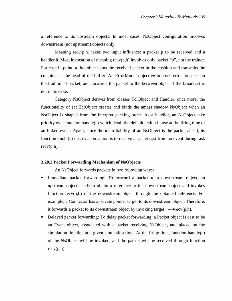
3.20.2 Packet Forwarding Mechanism of NsObjects
An NsObject forwards packets in two following ways:
Immediate packet forwarding: To forward a packet to a downstream object, an
upstream object needs to obtain a reference to the downstream object and invokes
function recv(p,h) of the downstream object through the obtained reference. For
example, a Connector has a private pointer target to its downstream object. Therefore,
it forwards a packet to its downstream object by invoking target recv(p,h).
Delayed packet forwarding: To delay packet forwarding, a Packet object is cast to be
an Event object, associated with a packet receiving NsObject, and placed on the
simulation timeline at a given simulation time. At the firing time, function handle(e)
of the NsObject will be invoked, and the packet will be received through function
recv(p,h).
Chapter 3Materials & Methods 136
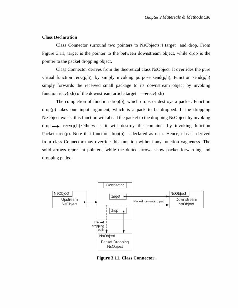
Class Declaration
Class Connector surround two pointers to NsObjects:4 target and drop. From
Figure 3.11, target is the pointer to the between downstream object, while drop is the
pointer to the packet dropping object.
Class Connector derives from the theoretical class NsObject. It overrides the pure
virtual function recv(p,h), by simply invoking purpose send(p,h). Function send(p,h)
simply forwards the received small package to its downstream object by invoking
function recv(p,h) of the downstream article target recv(p,h)
The completion of function drop(p), which drops or destroys a packet. Function
drop(p) takes one input argument, which is a pack to be dropped. If the dropping
NsObject exists, this function will ahead the packet to the dropping NsObject by invoking
drop recv(p,h).Otherwise, it will destroy the container by invoking function
Packet::free(p). Note that function drop(p) is declared as near. Hence, classes derived
from class Connector may override this function without any function vagueness. The
solid arrows represent pointers, while the dotted arrows show packet forwarding and
dropping paths.
Figure 3.11. Class Connector.
Chapter 3Materials & Methods 137
3.20.3 Packet Forwarding Mechanism
An NsObject forwards a small package in two ways: immediate and delayed
packet forwarding. We demonstrates both the packet forwarding mechanisms through a
Connector.
Immediate Packet Forwarding
Immediate packet forwarding is carried out by invoking purpose recv(p,h) of a
downstream object. The Connector forwards a small package to the TCP object by
invoking function recv(p,h) of the TCP object target recv(p,h), where aim is
configured to be a TCP object. C++ polymorphism is to blame for associating function
recv(p,h) to class TCP of construction type, not NsObject of assertion type.
Delayed Packet Forwarding
Delayed small package forwarding is implemented with the aid of the Scheduler.
Here, a packet is cast to an event, linked with a receiving NsObject, and placed on the
simulation timeline. For example, to delay packet forward in d seconds, we may invoke
the following statement instead of aim recv(p,h).
Consider Figure 3.12 shows the plan of delayed packet forwarding, while the
details of functions schedule(h,e,delay) as well as send out(p,t) of class Scheduler. When
schedule(target, p, d) is invoked, function schedule() casts carton pointer p and the
NsObject pointer target into Event and Handler objects. connections packet pointer p
with the NsObject pointer target. Insert packet pointer p into the imitation timeline at the
appropriate time. At the firing time, the event ( pointer p) is dispatch. The Scheduler
invokes function handle(p) of the handler associated with event baton p. In this case, the
associated handler is the NsObject pointer target. The default action handle(p) of target,
invokes purpose recv(p,h) to receive the scheduled packet.

Chapter 3Materials & Methods 138
3.21 Nodes as Routers or Computer Hosts
3.21.1 An Overview of Nodes in NS2
A Node plays two significant roles in NS2. As a router, it forwards packets to the
connecting link based on a direction-finding table. As a host, it delivers packets to the
transport layer agent attached to the port particular in the packet header. NS2 configures
the connection to its downstream NsObjects only. A Node does not require to have a
connection to its upstream NsObject e.g. a sending move agent or an upstream link.
Instead, its upstream NsObject will create a correlation to the Node.
Figure 3.12. Delayed packet forwarding.
3.21.2 Architecture of a Node
In the OTcl field, a Node is defined in a C++ class Node which is bound to an
OTcl class with the same name. A Node is a amalgamated object whose architecture is
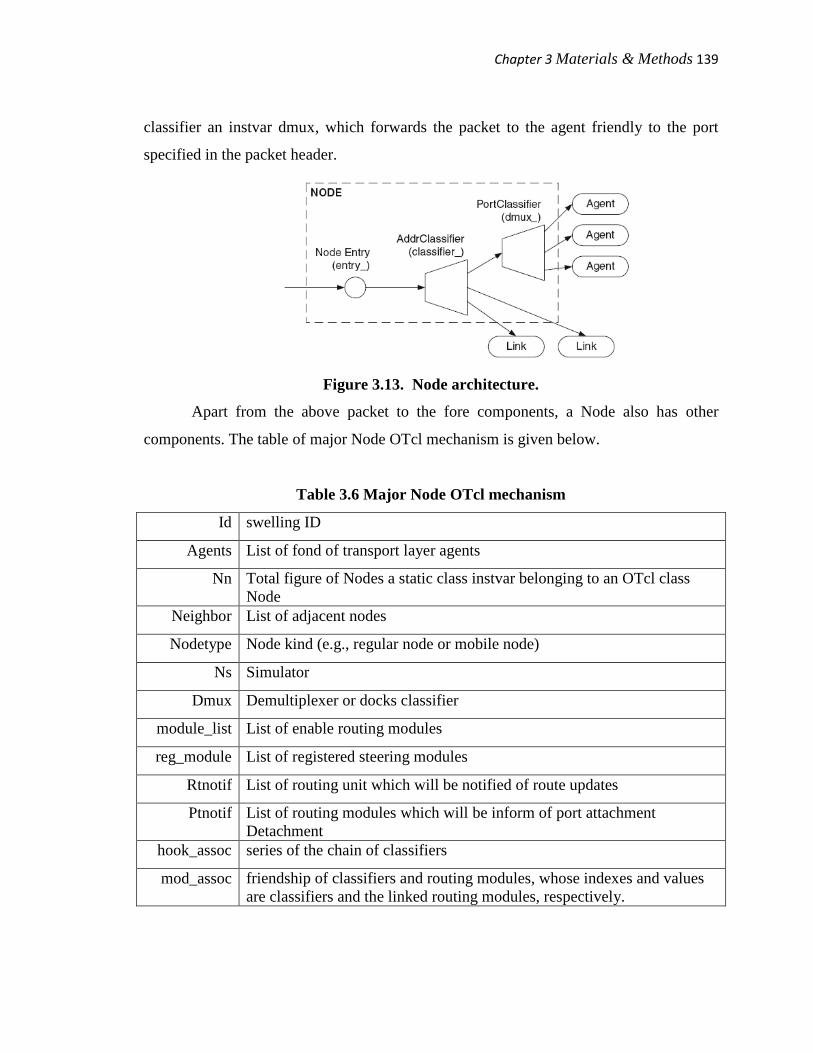
shown in Figure. 3.13. It provides a single point of packet opening,
Entry which is a Connector object. After toward the inside the Node entry, the
packet enters an address classifier an instvar classifier. If the Node is not the concluding
destination, the address classifier will forward the sachet to the link specified in the
routing table. Otherwise, it will forward the packet to the demultiplexer or docks
Chapter 3Materials & Methods 139
classifier an instvar dmux, which forwards the packet to the agent friendly to the port
specified in the packet header.
Figure 3.13. Node architecture.
Apart from the above packet to the fore components, a Node also has other
components. The table of major Node OTcl mechanism is given below.
Table 3.6 Major Node OTcl mechanism
Id swelling ID
Agents List of fond of transport layer agents
Nn Total figure of Nodes a static class instvar belonging to an OTcl classNode
Neighbor List of adjacent nodes
Nodetype Node kind (e.g., regular node or mobile node)
Ns Simulator
Dmux Demultiplexer or docks classifier
module_list List of enable routing modules
reg_module List of registered steering modules
Rtnotif List of routing unit which will be notified of route updates
Ptnotif List of routing modules which will be inform of port attachmentDetachment
hook_assoc series of the chain of classifiers
mod_assoc friendship of classifiers and routing modules, whose indexes and valuesare classifiers and the linked routing modules, respectively.

Chapter 3Materials & Methods 140
3.21.3 Related Instproc of Class Node
An OTcl class Node defines the following main instprocs, which can be classified
into three categories.
Initialization Instprocs
enable-module(mod_name) Appends mod_name to the module list module_list.
disable-module
(mod_name)
Removes mod_name from the module list module_list.
register-module(mod) Inserts an input routing module mod into an entry of the
instance associative array reg_module whose index in the
module name.
unregister-module(mod) Removes an entry of an instance associative array
reg_module whose index matches with the name of the
input routing module mod.
route-notify(module) Inserts an input routing module into the route notification
list rtnotif.
unreg-route-notify(module) Removes a routing module from the route notification list
rtnotif.
port-notify(module) Inserts an input routing module into the agent attachment
list ptnotif.
unreg-port-notify(module) Removes an input routing module from the agent
attachment list ptnotif.
Route Adding/Deleting and Agent Attachment/Detachment Instprocs
add-route(dst
target)
Recursively adds a routing entry (dst, target), where dst and target are
a destination node and a forwarding NsObject, respectively, for all
routing modules in the link list rtnotif .
delete-route(args) Recursively removes a routing entry specifies in the input arguments
from all routing modules in the linked list rtnotif.
alloc-port Returns a free port of the demultiplexer dmux of the Node.
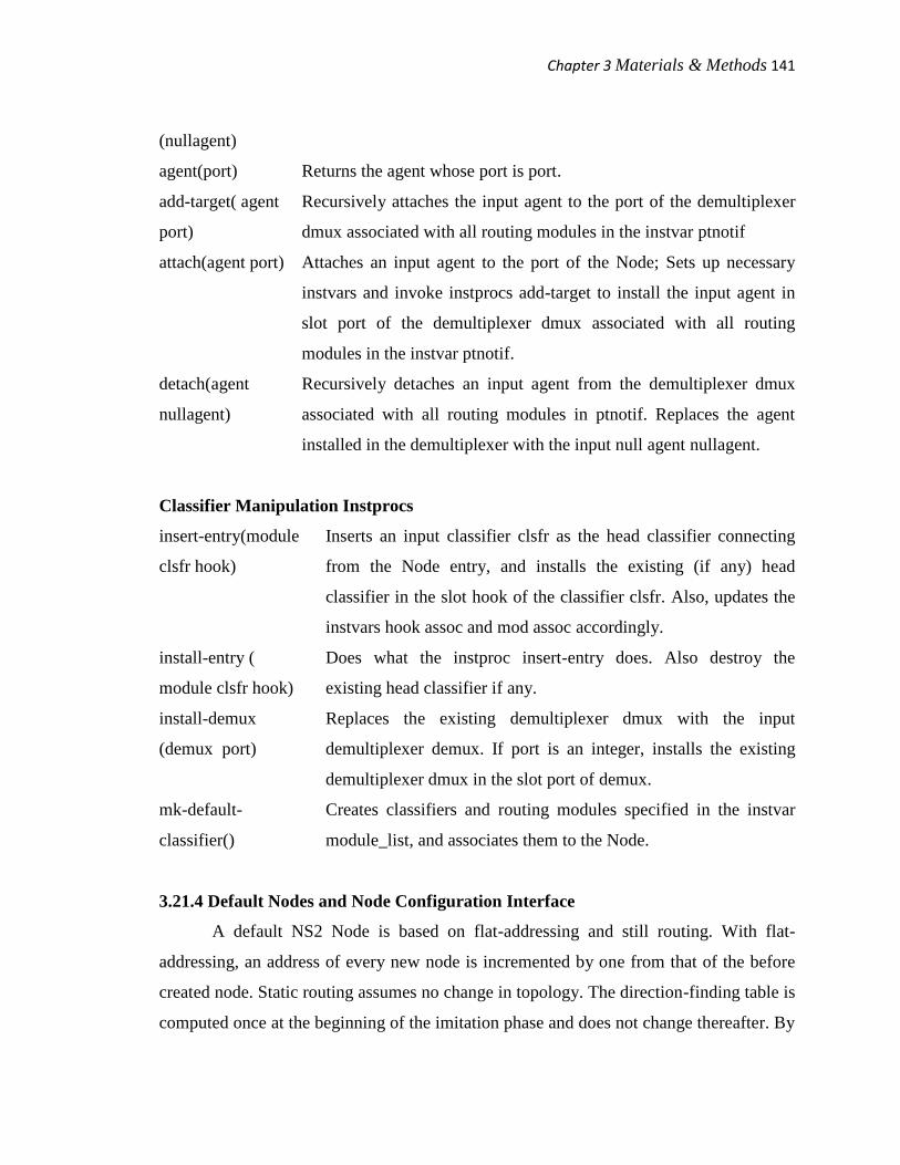
Chapter 3Materials & Methods 141
(nullagent)
agent(port) Returns the agent whose port is port.
add-target( agent
port)
Recursively attaches the input agent to the port of the demultiplexer
dmux associated with all routing modules in the instvar ptnotif
attach(agent port) Attaches an input agent to the port of the Node; Sets up necessary
instvars and invoke instprocs add-target to install the input agent in
slot port of the demultiplexer dmux associated with all routing
modules in the instvar ptnotif.
detach(agent
nullagent)
Recursively detaches an input agent from the demultiplexer dmux
associated with all routing modules in ptnotif. Replaces the agent
installed in the demultiplexer with the input null agent nullagent.
Classifier Manipulation Instprocs
insert-entry(module
clsfr hook)
Inserts an input classifier clsfr as the head classifier connecting
from the Node entry, and installs the existing (if any) head
classifier in the slot hook of the classifier clsfr. Also, updates the
instvars hook assoc and mod assoc accordingly.
install-entry (
module clsfr hook)
Does what the instproc insert-entry does. Also destroy the
existing head classifier if any.
install-demux
(demux port)
Replaces the existing demultiplexer dmux with the input
demultiplexer demux. If port is an integer, installs the existing
demultiplexer dmux in the slot port of demux.
mk-default-
classifier()
Creates classifiers and routing modules specified in the instvar
module_list, and associates them to the Node.
3.21.4 Default Nodes and Node Configuration Interface
A default NS2 Node is based on flat-addressing and still routing. With flat-
addressing, an address of every new node is incremented by one from that of the before
created node. Static routing assumes no change in topology. The direction-finding table is
computed once at the beginning of the imitation phase and does not change thereafter. By
Chapter 3Materials & Methods 142
default, NS2 employs the Dijkstra shortest path algorithm [178] to work out optimal
routes for all pairs of Nodes. The details about other direction-finding protocols as well
as hierarchical addressing can be found in the NS manual [179].
To provide a non-payment Node with more functionalities such as link layer or
Medium Access Control (MAC) procedure functionalities, we may use instproc node-
config of class Simulator whose grammar is as follows:
$ns node - config - <option> [<value>]
where $ns is the Simulator object. This instproc does not right away configure the Nodes
as specified in the <option>. in its place, it stores <value> in the instvars of the Simulator
corresponding to <option>. This stored pattern will be used during a Node construction
process. Therefore, this instproc must be effect prior to the Node creation.
An instance use of the instproc node-config(args) for the non-payment setting
is shown below:
$ns_ node - config - addressType flat
• adhocRouting
• llType
• macType
• propType
• ifqType
• ifqLen
• phyType
• antType
• channel
• channelType
• topologyInstance
By default, almost every option is specified as NULL with the exception of addressType,
which is set to be flat addressing. Another important option reset is used to restore default
parameter setting:
$ns node - config - reset

Chapter 3Materials & Methods 143
The details of instproc node-config can be found in the file
C:\cygwin\home\rakeshpoonia\ns-allinone-2.29\ns-2.29\tcl\lib\ns-lib.tcl.
3.22 Routing Mechanism in NS2
In general, a Node may attach to several downstream NsObjects. As a router, it
needs to select one of the downstream NsObjects as a forward NsObject for each
incoming packet. In most cases, this procedure is carried out using a so-called routing
table each row of which is called a routing entry. A routing admission specifies a
forwarding NsObject for a packet which matches a predefined criterion. For instance dst,
target specifies that, a packet whose destination address is dst, must be forward to a
forwarding NsObject target.
The routing mechanism in NS2 consists of four chief components:
• Routing agent: collects in order (e.g., the network topology) needed to compute a
routing table.
• Route logic: uses the in order collected by the routing agent, and compute the routing
table.
• Classifier: employs the computed routing bench for packet forwarding.
• Routing module: acts as a single point of organization of a group of classifiers in a
Node. It takes configuration commands from a direction-finding agent, a route logic,
and a Node, and propagates them to pertinent classifiers.
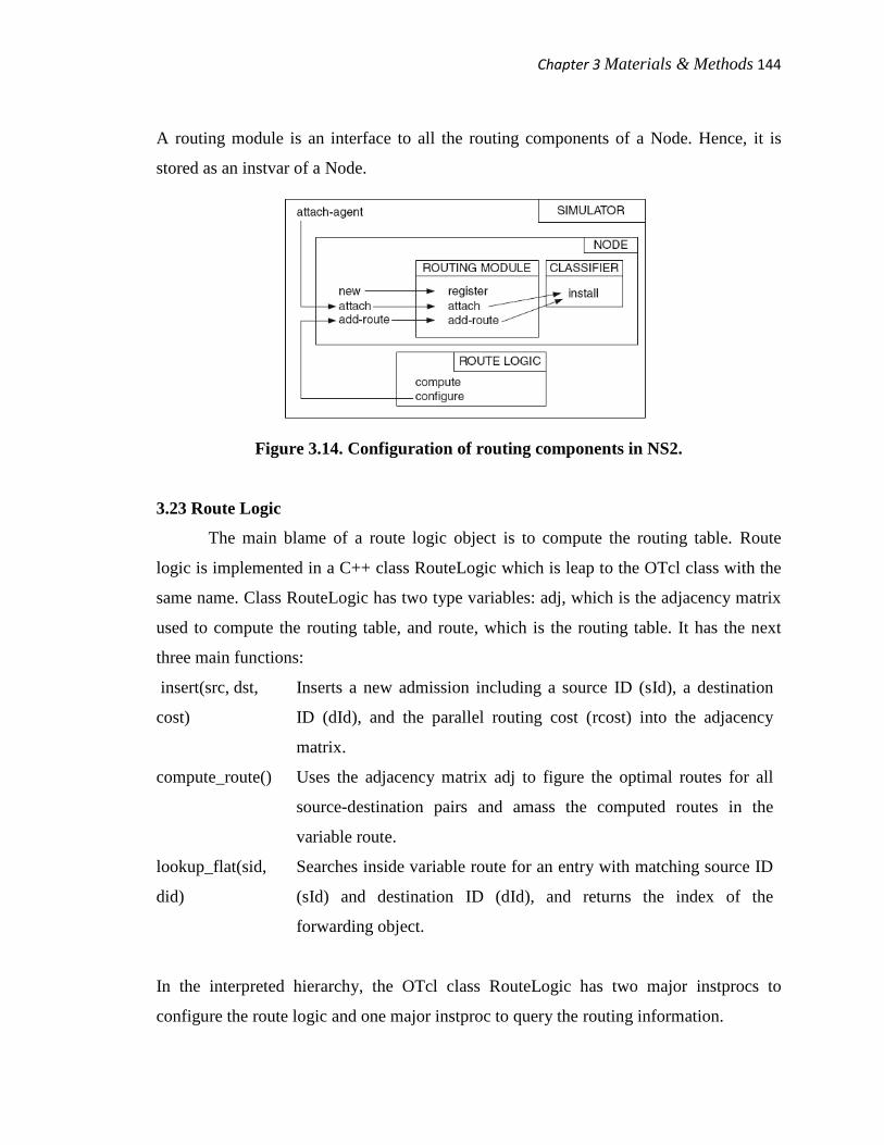
Figure 3.14. shows the routing components in NS2. Each box in this figure stand
for an object whose type is indicate on the top, while every utterance in a box represents
an instproc of the corresponding object. The arrow shows the series of instproc
invocation. For example, the instproc new() of the Node appeal to the instproc register of
the routing module.
Depending on their functionality, the above four direction-finding components are
stored in different simulation objects. A route reason computes the routing table for every
node. It is shared by several simulation objects, and is as a result stored in the Simulator.
Acting as a routing table, an address classifier is specific to and is hence stored in a Node.
Chapter 3Materials & Methods 144
A routing module is an interface to all the routing components of a Node. Hence, it is
stored as an instvar of a Node.
Figure 3.14. Configuration of routing components in NS2.
3.23 Route Logic
The main blame of a route logic object is to compute the routing table. Route
logic is implemented in a C++ class RouteLogic which is leap to the OTcl class with the
same name. Class RouteLogic has two type variables: adj, which is the adjacency matrix
used to compute the routing table, and route, which is the routing table. It has the next
three main functions:
insert(src, dst,
cost)
Inserts a new admission including a source ID (sId), a destination
ID (dId), and the parallel routing cost (rcost) into the adjacency
matrix.
compute_route() Uses the adjacency matrix adj to figure the optimal routes for all
source-destination pairs and amass the computed routes in the
variable route.
lookup_flat(sid,
did)
Searches inside variable route for an entry with matching source ID
(sId) and destination ID (dId), and returns the index of the
forwarding object.
In the interpreted hierarchy, the OTcl class RouteLogic has two major instprocs to
configure the route logic and one major instproc to query the routing information.
Chapter 3Materials & Methods 145
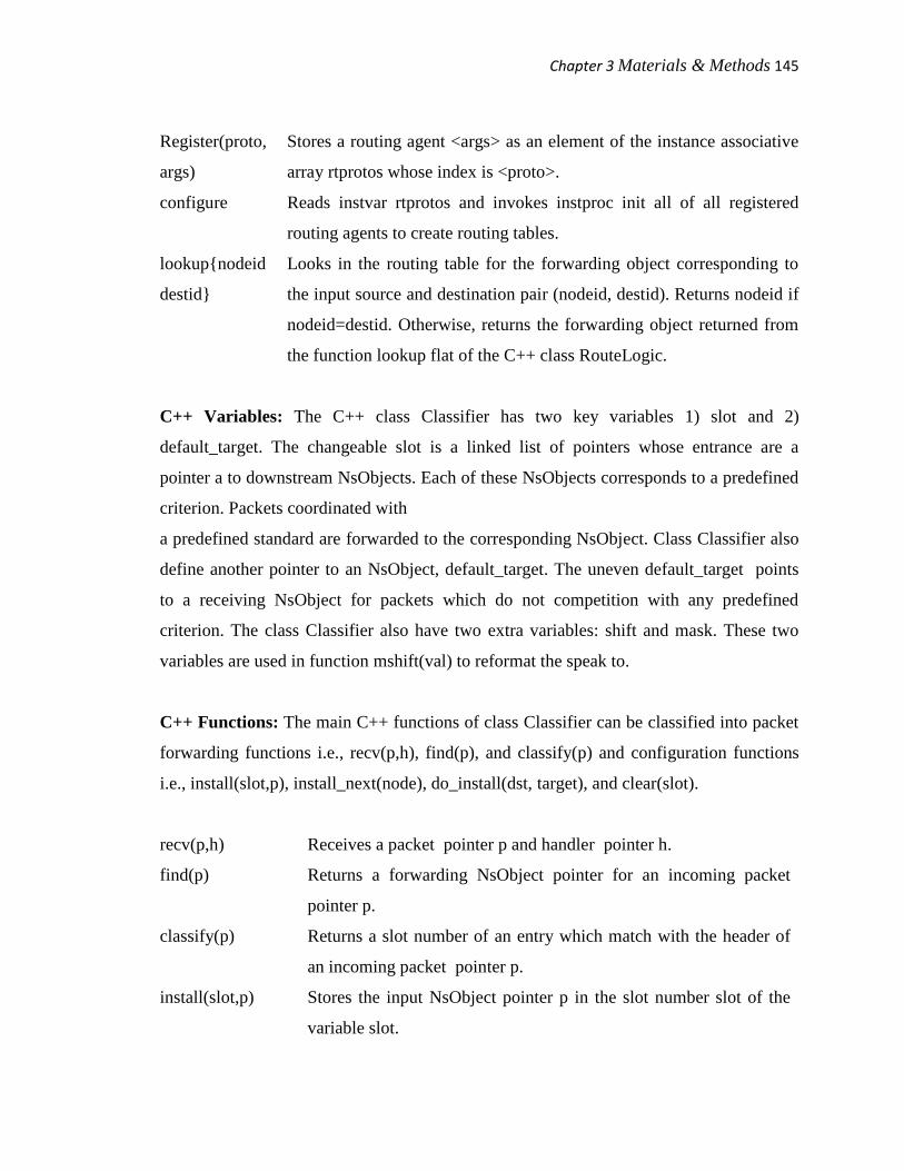
Register(proto,
args)
Stores a routing agent <args> as an element of the instance associative
array rtprotos whose index is <proto>.
configure Reads instvar rtprotos and invokes instproc init all of all registered
routing agents to create routing tables.
lookup{nodeid
destid}
Looks in the routing table for the forwarding object corresponding to
the input source and destination pair (nodeid, destid). Returns nodeid if
nodeid=destid. Otherwise, returns the forwarding object returned from
the function lookup flat of the C++ class RouteLogic.
C++ Variables: The C++ class Classifier has two key variables 1) slot and 2)
default_target. The changeable slot is a linked list of pointers whose entrance are a
pointer a to downstream NsObjects. Each of these NsObjects corresponds to a predefined
criterion. Packets coordinated with
a predefined standard are forwarded to the corresponding NsObject. Class Classifier also
define another pointer to an NsObject, default_target. The uneven default_target points
to a receiving NsObject for packets which do not competition with any predefined
criterion. The class Classifier also have two extra variables: shift and mask. These two
variables are used in function mshift(val) to reformat the speak to.
C++ Functions: The main C++ functions of class Classifier can be classified into packet
forwarding functions i.e., recv(p,h), find(p), and classify(p) and configuration functions
i.e., install(slot,p), install_next(node), do_install(dst, target), and clear(slot).
recv(p,h) Receives a packet pointer p and handler pointer h.
find(p) Returns a forwarding NsObject pointer for an incoming packet
pointer p.
classify(p) Returns a slot number of an entry which match with the header of
an incoming packet pointer p.
install(slot,p) Stores the input NsObject pointer p in the slot number slot of the
variable slot.
Chapter 3Materials & Methods 146
install_next(node) Installs the NsObject pointer node in the next available slot.
do_install(dst,
target)
Installs an input NsObject pointer target in the slot number dst.
clear(slot) Removes the NsObject pointer installed in the slot number slot.
mshift(val) Shifts val to the left by shift bits. Masks the shifted value by using a
logical AND (&) operation with mask.
3.24 An Overview of Packet Modeling Principle
3.24.1 Packet Architecture
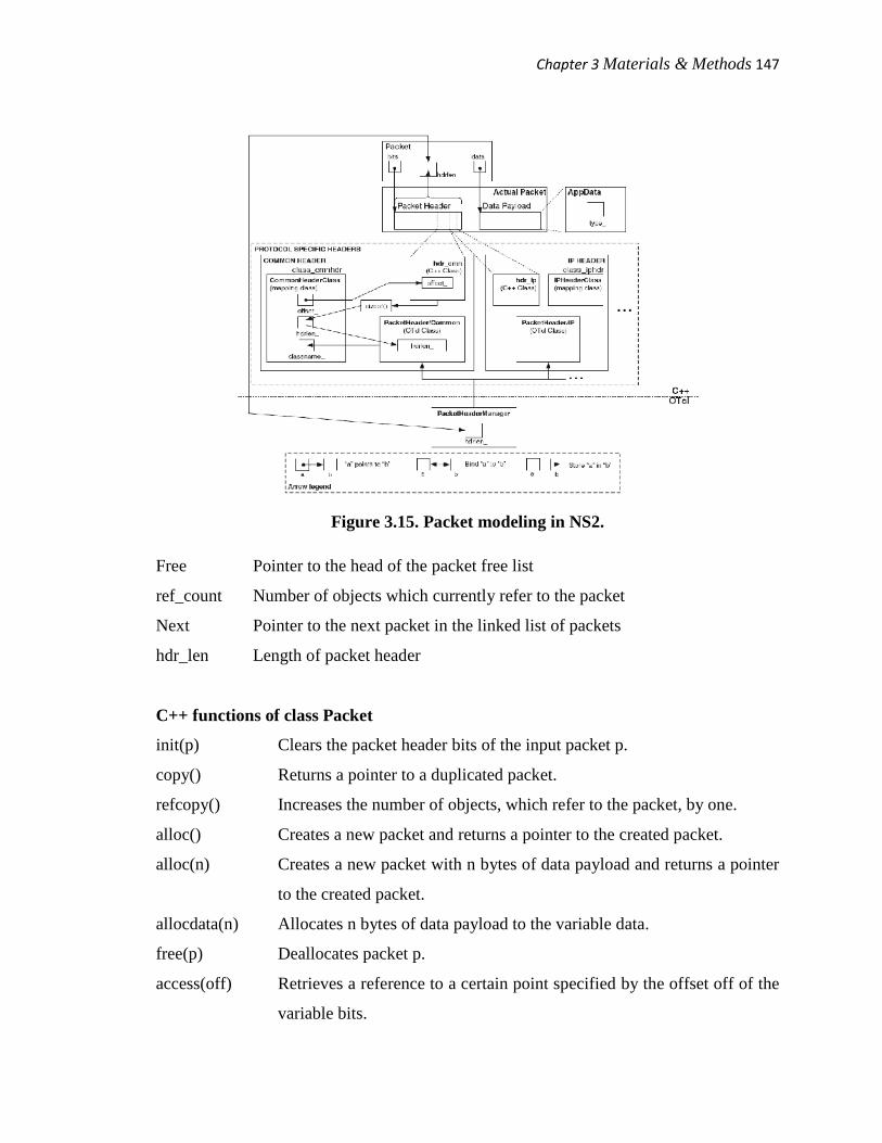
Figure 3.14 shows the planning of an NS2 packet model. From Figure 3.14, a
packet model consists of four most important parts:
a) actual small package,
b) class small package,
c) protocol exact headers, and
d) packet header boss.
• Actual Packet: An actual small package refers to the portion of memory which stores
packet header and data payload. NS2 does not honestly access either the packet
header or the data payload. quite, it uses pointers bits and data of class Packet to
access packet header and data payload, respectively.
• Class Packet: Class Packet is the C++ main class which represents packets. It
contains the following variables and functions.
• C++ variables of class Packet
Bits A string which contains packet header
Data Pointer to an AppData object which contains data payload
Fflag Set to true if the packet is currently referred to by other objects and false
otherwise
Chapter 3Materials & Methods 147
Figure 3.15. Packet modeling in NS2.
Free Pointer to the head of the packet free list
ref_count Number of objects which currently refer to the packet
Next Pointer to the next packet in the linked list of packets
hdr_len Length of packet header
C++ functions of class Packet
init(p) Clears the packet header bits of the input packet p.
copy() Returns a pointer to a duplicated packet.
refcopy() Increases the number of objects, which refer to the packet, by one.
alloc() Creates a new packet and returns a pointer to the created packet.
alloc(n) Creates a new packet with n bytes of data payload and returns a pointer
to the created packet.
allocdata(n) Allocates n bytes of data payload to the variable data.
free(p) Deallocates packet p.
access(off) Retrieves a reference to a certain point specified by the offset off of the
variable bits.
Chapter 3Materials & Methods 148
• Protocol Specific Header: From Figure 3.14, small package header consists of
several protocol specific headers. Each protocol specific slogan uses a contiguous
portion of packet header to store its packet characteristic. In common with most
TclObjects, there are three classes related to each protocol precise header: a C++
class, an OTcl class, and a mapping class.
• A C++ class provides a arrangement to store packet attributes.
• An OTcl class acts as an border to the OTcl domain. NS2 uses this class to configure
packet header from the OTcl area.
• A mapping set binds a C++ class to an OTcl class.
• Packet Header Manager: A sachet header manager maintains a list of active
protocols, and configures all active procedure specific headers to setup a packet
header. It has an instvar hdrlen which indicates the distance end to end of packet
header consisting of protocol specific headers. Instvar hdrlen is jump to a variable
hdrlen of class Packet. Any change in one of these two variables will consequence in
an automatic change in another.
• Data Payload: The pointer information points to data payload, which is of class
AppData.
3.24.2 A Packet as an Event: A Delayed Packet Reception Event
Derived from set Event, class Packet can be placed on the simulation time line.
We mentioned two main classes derived as of class Event 1) class AtEvent and 2) class
Packet. We also mentioned that an AtEvent object is an event shaped by a user from a Tcl
simulation script.
NS2 models a delayed action by insertion an event corresponding to the action on
the simulation timeline at a certain delayed time. Derived from set Event, class Packet
can be placed on the simulation timeline to signify a delayed sachet reception. For
example, the following statement schedules a packet reaction event, where the NsObject
pointer target receives a packet pointer p at txt+delay seconds in potential:
s.schedule(target, p, txt + delay)

Chapter 3Materials & Methods 149
where function schedule() of class Scheduler takes an occasion pointer as its second input
argument. A Packet pointer is shed to be an Event pointer before being fed as the second
input quarrel.
At the firing time, the Scheduler dispatches the listed event (i.e., pointer p) and
invokes target handle(p),which executes target recv(p) to onward packet pointer
p to the NsObject pointer end.
3.25 Packet Allocation and Deallocation
nothing like most of the NS2 objects, a Packet object is allocated and deallocated
using static functions alloc() and free(p) of class container, respectively. If possible,
function alloc() takes a Packet object from the free sachet list. Only when the free packet
list is empty, does the function alloc() creates a new Packet object using new. Function
free(p) deallocates a sachet object, by returning the memory billed for packet header and
data payload to the system and storing the not-in-use Packet pointer p in the gratis packet
list for future reuse.
3.25.1 Packet Allocation
The particulars of function alloc() of class Packet, the packet allocation function.
Function alloc() returns a stick to an allocated Packet object to the caller. This function
consists of two ingredient:
• packet allocation
• packet initialization.
think the packet allocation. Declares p as a pointer to a Packet object, and sets the
pointer p to point to the first packet on the free container list. If the free packet list is
empty i.e., p = 0, NS2 will create a new Packet object, and assign memory space with
size hdrlen bytes for the packet header. Variable hdrlen is not configured throughout the
construction of a Packet object. Rather, it is set up in the Network pattern Phase, and is
used by the function alloc() to create packet slogan.
Function alloc() does not assign memory space for data payload. When necessary,
NS2 creates data payload by using the job allocdata(n)
Chapter 3Materials & Methods 150
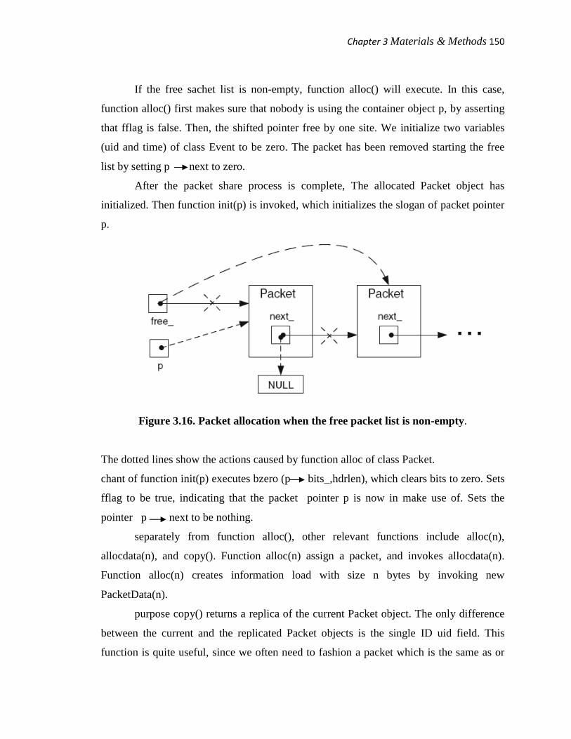
If the free sachet list is non-empty, function alloc() will execute. In this case,
function alloc() first makes sure that nobody is using the container object p, by asserting
that fflag is false. Then, the shifted pointer free by one site. We initialize two variables
(uid and time) of class Event to be zero. The packet has been removed starting the free
list by setting p next to zero.
After the packet share process is complete, The allocated Packet object has
initialized. Then function init(p) is invoked, which initializes the slogan of packet pointer
p.
Figure 3.16. Packet allocation when the free packet list is non-empty.
The dotted lines show the actions caused by function alloc of class Packet.
chant of function init(p) executes bzero (p bits_,hdrlen), which clears bits to zero. Sets
fflag to be true, indicating that the packet pointer p is now in make use of. Sets the
pointer p next to be nothing.
separately from function alloc(), other relevant functions include alloc(n),
allocdata(n), and copy(). Function alloc(n) assign a packet, and invokes allocdata(n).
Function alloc(n) creates information load with size n bytes by invoking new
PacketData(n).
purpose copy() returns a replica of the current Packet object. The only difference
between the current and the replicated Packet objects is the single ID uid field. This
function is quite useful, since we often need to fashion a packet which is the same as or

Chapter 3Materials & Methods 151
slightly different from an original packet. This function first allocate a packet pointer p.
Then, it copies packet header and data payload to the packet pointer p in that order.
Despite its name, purpose refcopy() does not create a copy of a Packet object.
Rather, it returns the pointer to the current Packet object. For instance, suppose p is a
Packet pointer. Then, x = p and x = p refcopy() both store p in x. However, purpose
refcopy() also keeps track of the number of objects which share the same small package
object, by using variable ref_count. This changeable is initialized to 0 in the constructor
of class Packet. It is incremented by one when function ref_copy() is invoked,
representative that a new object starts using the current Packet object. likewise, it is
decremented by one when function free(p) is invoked, indicating that an object has
stopped using the current small package object.
3.25.2 Packet Deallocation
When a packet pointer p is no longer in use, NS2 deallocates the envelope by
using function free(p). By deallocation, NS2 returns the reminiscence used to store packet
header and data payload to the system, sets the pole data to zero, and stores the Packet
object in the free packet list. Note that although the worth of bits is not set to zero, the
memory location stored in bits is no longer accessible by bits. It is very significant not to
use bits after packet deallocation. Otherwise, NS2 will meet a (memory share violation)
runtime error.
Before returning a pack object to the free packet list, we need to make sure that
The packet is in use p fflag = 1, because there is no point in deallocating a packet
which has by now been deallocated.
No object is using the packet; the changeable ref_count is Zero, where ref_count
stores the number of objects which are at present using the packet.
The packet is no longer on the imitation time line p uid_<=0. Deallocating a
packet while it is still on the imitation timeline will cause event miss sequencing and
runtime error. Asserts that the event unique ID equivalent to the Packet object p
p uid is non-positive, and therefore is no longer on the imitation timeline.
Chapter 3Materials & Methods 152
The data payload pointer statistics must not point to NULL p data=0, when
returning the memory occupied by data freight to the system.
NS2 allows more than one imitation object to share the same Packet object. To
deallocate a packet, NS2 must ensure that the pack is no longer used by any simulation
object. Again, NS2 keeps the number of objects sharing a sachet in variable ref_count.
If ref_count_>0–meaning an item is invoking function free(p) while other objects
are still using the packet pointer p, utility free(p) will simply reduce ref_count by one,
indicating that one object stops using the packet On the additional hand, if ref_count is
zero–meaning no other object is using the pack, then clear packet header and data
payload, and store the Packet object in the free packet catalog.
If all the above four conditions are satisfied, function free(p) will execute. The
schematic diagram for this part is shown in Figure 3.14. returns the memory used by data
payload to the system. The pointer data is sets to zero. The memory used by packet
header of a packet pointer p to the system is returns by invoking function init(p).
Function free(p) does not set the variable bit to zero. Do not try to access bit after this
point, since doing so will cause a runtime error. We place the packet as the first packet
on the free packet list. Finally, sets fflag to false, indicating that the packet is no longer in
use.
3.26 Packet Header
As a fraction of a packet, packet header contains packet attributes such as packet
unique ID, and IP address. once more, packet slogan is stored in variable bits of class
Packet. The variable bits is declared as a cord earnings a Bag of Bits (BOB), and has no
structure to store packet attributes. NS2 hence oblige a two-level structure on variable
bits, as shown in Figure 3.16.
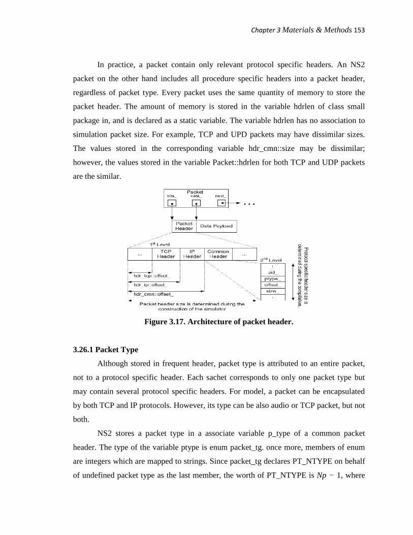
The first level divides the complete packet header into protocol specific headers.
The location of each protocol specific description on bits is identified by its variable
offset. The second level imposes a packet quality storing structure on each protocol
specific header. On this level, packet quality are stored as members of a C++ struct data
type.
Chapter 3Materials & Methods 153
In practice, a packet contain only relevant protocol specific headers. An NS2
packet on the other hand includes all procedure specific headers into a packet header,
regardless of packet type. Every packet uses the same quantity of memory to store the
packet header. The amount of memory is stored in the variable hdrlen of class small
package in, and is declared as a static variable. The variable hdrlen has no association to
simulation packet size. For example, TCP and UPD packets may have dissimilar sizes.
The values stored in the corresponding variable hdr_cmn::size may be dissimilar;
however, the values stored in the variable Packet::hdrlen for both TCP and UDP packets
are the similar.
Figure 3.17. Architecture of packet header.
3.26.1 Packet Type
Although stored in frequent header, packet type is attributed to an entire packet,
not to a protocol specific header. Each sachet corresponds to only one packet type but
may contain several protocol specific headers. For model, a packet can be encapsulated
by both TCP and IP protocols. However, its type can be also audio or TCP packet, but not
both.
NS2 stores a packet type in a associate variable p_type of a common packet
header. The type of the variable ptype is enum packet_tg. once more, members of enum
are integers which are mapped to strings. Since packet_tg declares PT_NTYPE on behalf
of undefined packet type as the last member, the worth of PT_NTYPE is Np − 1, where
Chapter 3Materials & Methods 154
Np is the number of packet_tg members. NS2 provides 60 built-in small package types,
meaning the default value of PT_NTYPE is 59.
Class p_info maps each associate of packet_tg to a description string. It has a
static associative array variable, name. The directory and value of name are the packet
type, and the corresponding description string, in that order. Class p info also has one
important function name(p), which translates a packet_tg changeable to a description
string.
NS2 declares a global changeable packet_info using extern key word, which is of
class p info. Accessible at the global capacity, the variable packet_info provides an
access to function name(p) of class p info. To obtain a explanation string of a packet_tg
object p, one may invoke.
packet_info.name(p_type)
Class Agent is responsible for create and destroying network layer packets. It is the base
class of TCP and UDP transport layer procedure modules. Class Agent provides a
function allocpkt(), which is responsible for assign and creating a packet.
To print out the type of every allocated sachet on the screen, we modify function
allocpkt() of class representative in file C:\cygwin\home\rakeshpoonia\ns-allinone-
2.29\ns-2.29\common\agent.cc as follows: to get back the reference ch to the common
packet header the packet type is obtain which is stored in the ordinary header by using
function p_type(), and assigns the packet type to changeable pt. Note that, variable
packet_info is a global variable of class p info. When the changeable pt is fed as an input
argument, function packet_info.name(pt) returns the description string equivalent to the
packet_tg object pt
After re-compiling the code, the simulation should show the type of every
allocated packet on the screen.
>> ns firstns.tcl
Example Test: Class Agent allocates a packet with type cbr
Example Test: Class Agent allocates a packet with type cbr
Example Test: Class Agent allocates a packet with type cbr
Example Test: Class Agent allocates a packet with type cbr
Chapter 3Materials & Methods 155
Example Test: Class Agent allocates a packet with type cbr
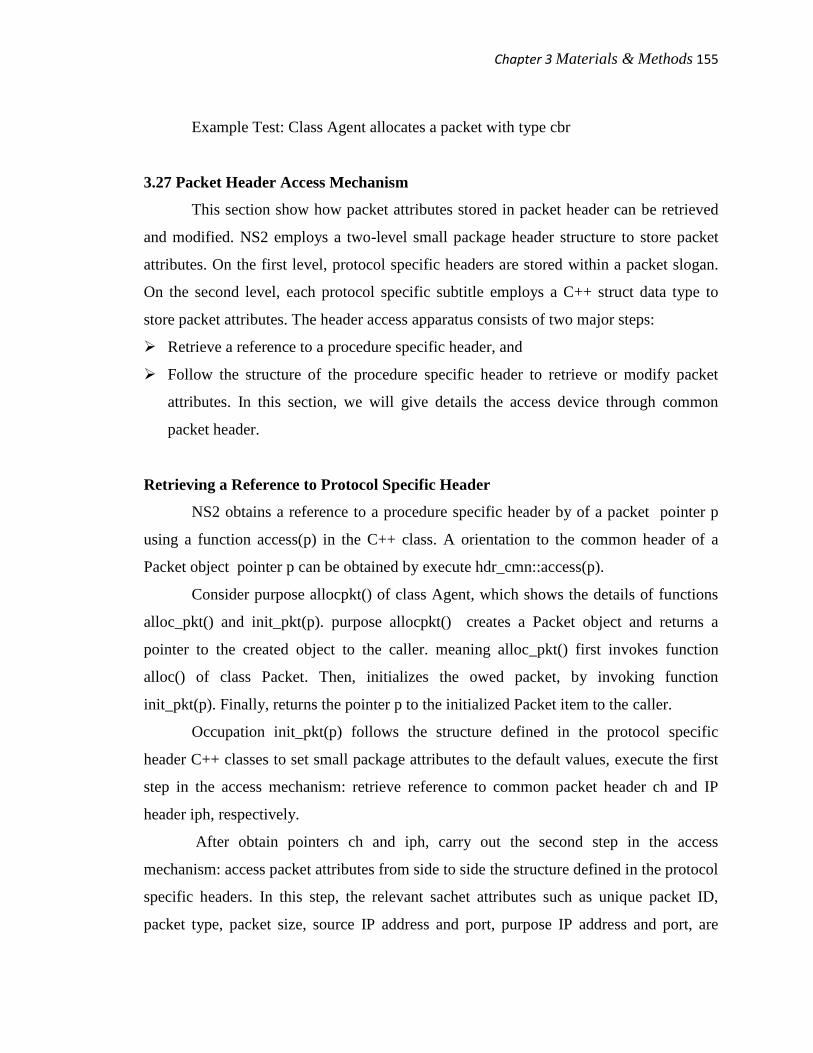
3.27 Packet Header Access Mechanism
This section show how packet attributes stored in packet header can be retrieved
and modified. NS2 employs a two-level small package header structure to store packet
attributes. On the first level, protocol specific headers are stored within a packet slogan.
On the second level, each protocol specific subtitle employs a C++ struct data type to
store packet attributes. The header access apparatus consists of two major steps:
Retrieve a reference to a procedure specific header, and
Follow the structure of the procedure specific header to retrieve or modify packet
attributes. In this section, we will give details the access device through common
packet header.
Retrieving a Reference to Protocol Specific Header
NS2 obtains a reference to a procedure specific header by of a packet pointer p
using a function access(p) in the C++ class. A orientation to the common header of a
Packet object pointer p can be obtained by execute hdr_cmn::access(p).
Consider purpose allocpkt() of class Agent, which shows the details of functions
alloc_pkt() and init_pkt(p). purpose allocpkt() creates a Packet object and returns a
pointer to the created object to the caller. meaning alloc_pkt() first invokes function
alloc() of class Packet. Then, initializes the owed packet, by invoking function
init_pkt(p). Finally, returns the pointer p to the initialized Packet item to the caller.
Occupation init_pkt(p) follows the structure defined in the protocol specific
header C++ classes to set small package attributes to the default values, execute the first
step in the access mechanism: retrieve reference to common packet header ch and IP
header iph, respectively.
After obtain pointers ch and iph, carry out the second step in the access
mechanism: access packet attributes from side to side the structure defined in the protocol
specific headers. In this step, the relevant sachet attributes such as unique packet ID,
packet type, packet size, source IP address and port, purpose IP address and port, are
Chapter 3Materials & Methods 156
configured through pointers ch and iph. Note that ui_dcnt that is uid count is a still
member variable of class Agent which represents the total figure of generated packets.
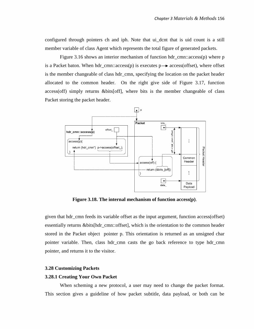
Figure 3.16 shows an interior mechanism of function hdr_cmn::access(p) where p
is a Packet baton. When hdr_cmn::access(p) is executes p access(offset), where offset
is the member changeable of class hdr_cmn, specifying the location on the packet header
allocated to the common header. On the right give side of Figure 3.17, function
access(off) simply returns &bits[off], where bits is the member changeable of class
Packet storing the packet header.
Figure 3.18. The internal mechanism of function access(p).
given that hdr_cmn feeds its variable offset as the input argument, function access(offset)
essentially returns &bits[hdr_cmn::offset], which is the orientation to the common header
stored in the Packet object pointer p. This orientation is returned as an unsigned char
pointer variable. Then, class hdr_cmn casts the go back reference to type hdr_cmn
pointer, and returns it to the visitor.
3.28 Customizing Packets
3.28.1 Creating Your Own Packet
When scheming a new protocol, a user may need to change the packet format.
This section gives a guideline of how packet subtitle, data payload, or both can be
Chapter 3Materials & Methods 157
modified. Note that, it is optional not to use data payload in simulation. If possible,
include information related to the new protocol in a protocol detailed header.
Defining a New Packet Header
presume we would like to include a new protocol specific header, namely “My
New Header”, into the packet header. We need to describe a C++ class (e.g., hdr_myhdr),
an OTcl class (e.g., PacketHeader/MyNewHeader), and a chart class (e.g.,
MyNewHeaderClass) for My New Header, and contain the OTcl class into the active
protocol list. In particular, we need to perform the following four ladder:
1) Define a protocol exact header C++ struct hdr_mynewhdr.
a) Declare changeable offset.
b) Define purpose access(p).
c) Include all associate variables required to hold new packet attributes.
d) Include a new small package type into enum packet_tg and class p info. Again, a
new packet type does not need to be added for every new procedure specific
header.
2) Define a code of behavior specific header OTcl class PacketHeader/MyNewHeader.
3) Derive a chart class MyNewHeaderClass from class PacketHeader Class.
i) At the construction, feed the matching OTcl class name (i.e.,
PacketHeader/MyNewHeader) and the dimension needed to hold the protocol
specific header (i.e., sizeof(hdr_mynewhdr)) to the constructor of class
PacketHeaderClass.
ii) From within the constructor, invoke purpose bind_offset() feeding the address
of the variable offset_ of the C++ struct data type as an input quarrel. i.e.,
invoke bind_offset(&hdr_mynewhdr::offset).
iii) Instantiate a mapping changeable class_mynewhdr at the statement.
4) Activate My Header by counting class PacketHeader/MyNewHeader into the active
protocol list.
Chapter 3Materials & Methods 158
Defining a New Data Payload
Data freight can be created in four levels:
1) None: NS2 rarely uses data payload in imitation. To avoid any complicacy, it is
suggested not to use data payload in imitation.
2) Use class PacketData:The simplest form of store up data payload is to use class
PacketData. Class Packet has a variable statistics whose class is PacketData and
provides functions to manipulate the patchy data.
3) Derive a class MyPacketData from class PacketData: This alternative is suitable when
new functionalities functions and variables in calculation to those provided by class
PacketData are needed. After deriving a new PacketData class, a user may also take a
new class (e.g., class MyPacket) from class carton, and override the variable data of
class Packet to be a pointer to a MyPacketData thing.
4) Define a new data load class: A user can also define a new payload type if needed.
This option should be used when the new payload has zero in common with class
PacketData. The followings are the main tasks needed to describe and use a new
payload type MY_DATA.
• Include the new load type (e.g., MY_DATA) into enum AppDataType data type.
• Derive a new load class MyData from class AppData.
Feed the load type MY_DATA to the constructor of class AppData.
Include any other necessary purpose and variables.
supersede functions size() and copy().
• get a new class MyPacket from class Packet
Declare a uneven of class MyData to store data payload.
Include functions to influence the above MyData variable.
3.28.2 Activate/Deactivate a Protocol Specific Header
By default, NS2 includes all built-in protocol detailed headers into packet header.
This inclusion can lead to unnecessary wastage of reminiscence especially in a packet-
intensive simulation, where numerous packets are fashioned. For example, common, IP,
Chapter 3Materials & Methods 159
and TCP headers together use only 0.1 kB, while the default packet legend consumes as
much as 2.4 kB [178]. Again, NS2 does not return the memory owed to a Packet object
until the simulation terminates. Selectively including protocol specific slogan can lead to
huge memory saving.
The packet format is distinct when the Simulator is created. Therefore, a protocol
specific headers must be activated/deactivated prior to the formation of the Simulator.
NS2 provides the following OTcl procedures to activate/ neutralize protocol specific
headers:
• To add a protocol exact header PacketHeader/MH1, execute add-packet-header MH1.
The above declaration includes PacketHeader/MH1 to the changeable tab of class
PacketHeaderManager.
• To remove a protocol exact header PacketHeader/MH1 from the active list, carry out
remove-packet-header MH1
Chapter 4 Observations, result & Discussion 160
Chapter 4
Observation, result and Discussion
In this chapter we are going to propose and implement our new model for integration
system design for video delivery over heterogenous network, which definitely make our
research justified. We have first discussed about the existing routing protocol i.e. AODV
then the available modified version of AODV i.e. qAODV. We have proposed a new
concept in qAODV in respect of data rate and access admission control. This concept
have been proved successful which is represented with the help of simulation
environment created with ns2. We have also proposed an algorithm which represent
complete flow of steps from starting to the end for our proposed model. Simulation
results has been displayed with the help of quite a large number of graphs.
4.1 General idea of the AODV routing protocol
The “Ad hoc On-Demand Distance Vector (AODV) routing protocol” is in Ad
hoc network for mobile nodes. AODV is quick in performing tasks likes.
• Dynamic link conditions.
• Low processing.
• Memory overhead.
• Low network utilization.
• Determines unicast routes destinations.
Problem associated with classical distance vector protocols like counting to
infinity can be avoided by ensuring loop freedom for all times using Destination
sequence numbers.
The order to maintain and establish Ad hoc network, AODV algorithm[180]
wishing to establish dynamic, self-starting, multihop routing between participating
mobile nodes. The working principle of AODV is that it does not required and maintain
Chapter 4 Observations, result & Discussion 161
routes which are not in active communication and it also allowed nodes to obtain quick
routes for new destinations, and it also allowed mobile nodes to respond to link breakages
and changes which are taking place in network topology.
When a node moves in networks the ad hoc topology will be changed and the
operation of AODV will be loop-free, and by avoiding the Bellman-Ford “counting to
infinity”' quick convergence can be offered. In case when links are breaking, then the
nodes must be notified so that routes will be invalidated and nodes of that particular route
are informed about the broken link. One important feature of AODV is that it uses one
destination sequence number for many route entries.
For every destination node a destination sequence number has been generated for
intermediate/requesting nodes. With the help of destination sequence numbers we can
ensures loop freedom of programmer to perform simple program. In order to perform
data or video transmission over ad hoc network, route will be selected according to the
greatest destination sequence number i.e. requesting node will select the route with
greatest sequence number. There are three messages type which are defined by
AODV[181] they are as follows.
1. Route Requests (RREQs)
2. Route Replies (RREPs)
3. Route Errors (RERRs)
These messages are used by AODV to manage Route Request means whenever
any node request for route he must send route request message to neighborhood nodes so
that they came to know that a particular node is waiting for data transfer and they
responds according to availability of data rate and other parameters. Similarly Route
Reply message means whenever any intermediate nodes get the message from neighbours
node about the route then these nodes will responds by passing message of Route Reply
to the sender node that route is ready for transfer. Route Error means whenever any
intermediate node is not able to transfer data to further node, because lack of data rate or
any other region then route error message is generated by that node and this message is
broadcasted to all the routes passing through that node so that further transmission is not
Chapter 4 Observations, result & Discussion 162
suffered. These three messages can be received at port number 654, these messages are
received over UDP, and normal IP header.
The determination of route can be determined by using Route Request message.
When that message is floated either the destination or any intermediate node is generating
a fresh enough request to the destination. The fresh enough request that is generated by
nodes is an unexpired route entry whose destination sequence number is greater than the
sequence number of Route Request message. A route will be created by unicasting a
Route Reply message back to source of request. Route Reply messages travels in back
ward direction i.e. from destination to source and this message will pass through all the
intermediate nodes those who occurred in that route. Whenever the data in form of nodes
are moving towards destination then AODV has created route table, with the help of this
route table we can link the next node in that active route. Route table has various fields
used in AODV are using the following fields of route table[182]:
• Destination IP Address.
• Destination Sequence Number.
• Interface.
• Hop Count.
• Last Hop Count.
• Next Hop
• List of Precursors.
• Lifetime.
• Routing Flags
When a node is not reachable or its link is break down and is not able to supply its
information about its sequence number then it is very crucial to avoid routing loops.
Whenever the link is break or complete path is disable and any problem is occurred then
it is impossible to reach destination. When such condition is occurred then the complete
route is invalidated by the various operation involve in destination sequence number and
hop count.
Chapter 4 Observations, result & Discussion 163
4.2 General idea of the qAODV routing protocol
We are implementing qAODV procedure with two parameters Data Rate and
Access Admission Control (AAC) and compare with obtainable AODV procedure in
NS2. In section 4.3.1 we calculate AODV Data Rate, we have intended the present data
rate which have been attain in general AODV. In section 4.3.2 computation of AAC in
AODV protocol, we have implemented the Access right of entry Control in progress
AODV then we have premeditated the data rate. The foremost perception for which we
are track our research is to put into practice the QoS in the current AODV.
4.3 Proposed Model
With the help of Figure 4.1 the proposed model is shown in form of flowchart.
The main focus was given on data rate, that what action should be taken when data rate
reaches below certain level. Some data rate restrictions are added during the transmission
of the AODV routing packets.
In qAODV, we focus on data rate and check every node with sufficient available
data rate since we know that a node with accessible data rate can only take part in data
transfer or in route finding using Route Request and Route Reply message. Data Rate of
each node is defined in advance by fix number. By doing simulation on NS2 with same
environment in AODV and qAODV we can decided available Data Rate. With the help
these simulating results we are trying to get the maximum throughput between the nodes
who are having same data rate. The process of approximation of data rate obtain through
simulation result will be discuss in coming section.
Nodes in network are always in moving condition because of this data rate of each
node is keep on changing and i.e. data rate of each node is monitor and keep in record.
There are various region that may cause change in data rate like moving capability of
nodes, collision of nodes, intermediate node taking part in transmission etc. If nodes with
available data rate reaches below certain level which is preset before we start the
transmission that means that the node is overloaded and if that node is taking part in
transmission then this node is not able to send data to next node so, he must release all
other tasks assign to that node, so that node will gain the data rate again and now this
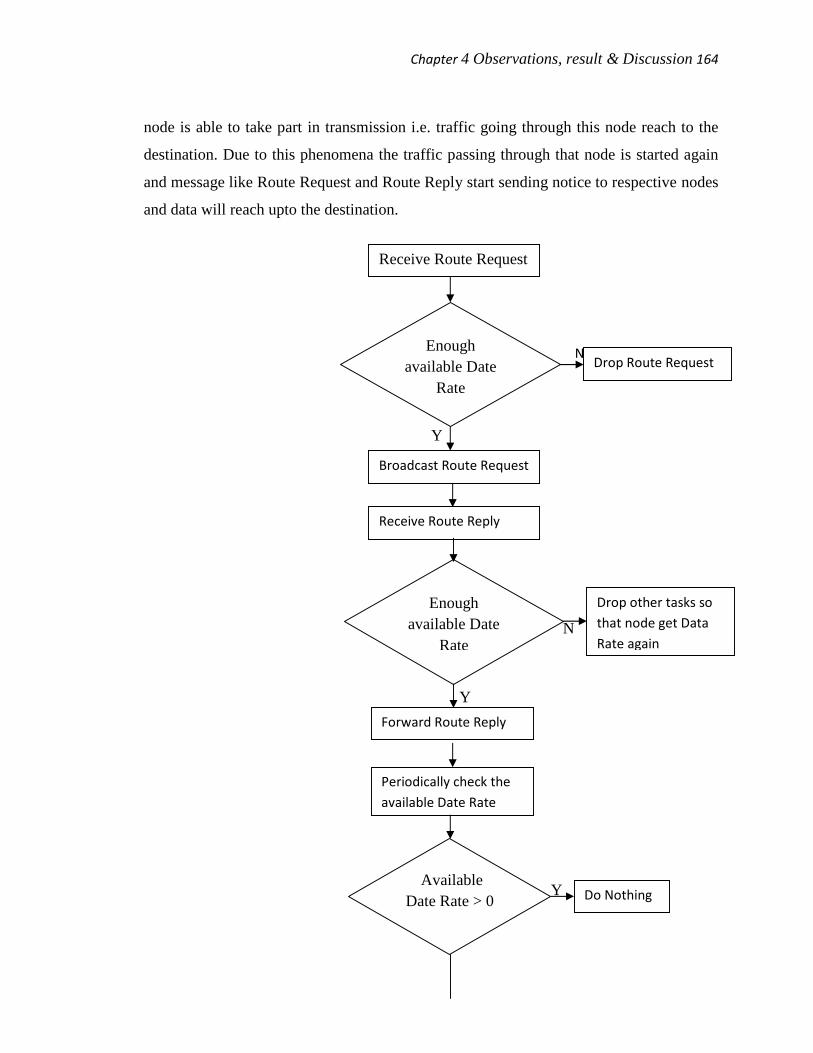
Chapter 4 Observations, result & Discussion 164
node is able to take part in transmission i.e. traffic going through this node reach to the
destination. Due to this phenomena the traffic passing through that node is started again
and message like Route Request and Route Reply start sending notice to respective nodes
and data will reach upto the destination.
N
Y
N
Y
YY
YY
Receive Route Request
Enoughavailable Date
Rate
Broadcast Route Request
Drop Route Request
Receive Route Reply
Enoughavailable Date
Rate
Drop other tasks sothat node get DataRate again
Forward Route Reply
Periodically check theavailable Date Rate
AvailableDate Rate > 0 Do Nothing

Chapter 4 Observations, result & Discussion 165
N
N
Y
Figure 4.1 Flow Chart
Algorithm of proposed model.
Step 01: Start
Step 02: Get route request for receiving new data in variable r_req.
Step 03: Check for enough available Data Rate of intermediate nodes.
Step 04: If yes then broad cast route request r_req.
Step 05: If no then Drop route request r_req.
Step 06: Get route reply from intermediate nodes in variable r_rep.
Step 07: Check for enough available Data Rate of intermediate nodes.
Step 08: If yes then forward route reply i.e. r_rep.
Step 09: If no then node should drop other task so that node get the data rate again.
Step 10: Check periodically available data rate.
Send Message thatpath lost
Receive Message thatpath lost
Whether I amsource node
Stop Traffic
Forward Path LostMessage
Chapter 4 Observations, result & Discussion 166
Step 11: Check whether available data rate > 0.
Step 12: If yes then do nothing.
Step 13: If no then send message that path lost.
Step 14: Source node get message that path lost.
Step 15: Check whether current node is source node.
Step 16: If no then forward path lost message.
Step 17: If yes then stop traffic.
Step 18: End.
4.3.1 AODV Data Rate
Every node has a data rate that is calculated by itself. Data Rate of any node is
keep on decreasing as that node start moving in network and its total data rate is
subtracting from the total data rate used by that node and its surrounding node. In the
following section we are calculating the available data rate which is generally called as
locally available data rate.
1. In this case we calculate the ratio of time when node is idle. For this we are
calculating two parameters namely a) Idle time of node in window b) Total
simulation time. Link consumption (λ) is ratio of active time and total simulation
time. The total time used for observing is called window duration. So (1- λ) is the
ratio of idle time of node.
λ = Busy Time/Total Simulation Time.
2. In this method we calculate the real data rate which is used for data transmission, this
is called throughput. Every node receive data packets with different size in bits. These
packets are transmitted and we calculate the time taken by these packets to transmit
these bits. The time taken for transmitting the bits is combination of time taken when
channel is used for transmission and time to check the accurate and non clash
broadcast of these bits. Following parameters are used a) Time for pass on N bits
includes queuing time t_queue b) Transmission time of N bits is t_xfer c) Collision
avoidance phase time t_collavoid d) Control overhead time t_contoverhead e) Back
off time B_offtime and R is retransmission time.
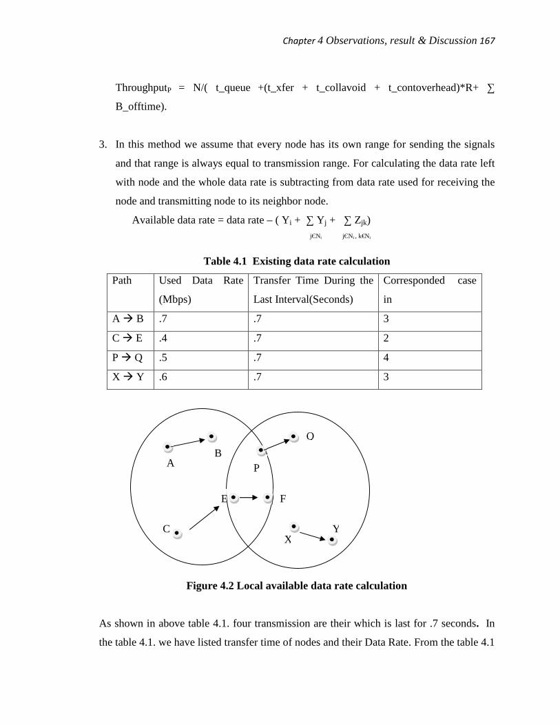
Chapter 4 Observations, result & Discussion 167
ThroughputP = N/( t_queue +(t_xfer + t_collavoid + t_contoverhead)*R+ ∑
B_offtime).
3. In this method we assume that every node has its own range for sending the signals
and that range is always equal to transmission range. For calculating the data rate left
with node and the whole data rate is subtracting from data rate used for receiving the
node and transmitting node to its neighbor node.
Available data rate = data rate – ( Yi + ∑ Yj + ∑ Zjk)jЄNi jЄNi , k€Ni
Table 4.1 Existing data rate calculation
Path Used Data Rate
(Mbps)
Transfer Time During the
Last Interval(Seconds)
Corresponded case
in
A B .7 .7 3
C E .4 .7 2
P Q .5 .7 4
X Y .6 .7 3
Figure 4.2 Local available data rate calculation
As shown in above table 4.1. four transmission are their which is last for .7 seconds. In
the table 4.1. we have listed transfer time of nodes and their Data Rate. From the table 4.1
AB
C
E F
Q
P
XY

Chapter 4 Observations, result & Discussion 168
it is clear that largest throughput is 3 mbps. Since we know that the existing data rate of
nodes is changes very often so we keep on calculate the data rate after small interval.
Using the below mention formula we can calculate existing data rate of Node E which is
last for 0.7 seconds.
Available data rate (A) = 3 mbps - 0.7 mbps - 0.4 mbps - 0.5 mbps - 0.6 mbps = 0.8 mbps
Above result shows that data rate of node is .8 mbps and it is not used during
transmission.
4. We can implement this method using NS2. Since we know that packets are of different
size and they are keep on moving. So we calculate the size of packets those who are sent,
received and sensed at the last period Tp. As in method 3 where we assume transmission
range and carrier sensing range are equal that seems unrealistic so in this case we
consider that range of node for sensing is the real interfering range for all the packets
which are sensed. Because of this the method look more real. According the formula we
calculate the sum to data rate of sent, receives and sensed bits and divides it by total
duration.
Np is packet node has sent.
Tp is total duration.
Sp is size of packet.
Data rate= ( Np * Sp * 8 )/ Tp
4.3.2 Calculation of AAC in AODV Protocol
Getting the information about the data rate of a node is not sufficient to get the
real picture of traffic. Since this information is not sufficient to check the flow of traffic.
We need to calculate the Admission control of every node during the path finding
process. We can calculate the Admission control for AODV routing protocol using
following methods.
1. During the calculation of data rate using method 3 we assume that carrier sensing
range is equal to transmission range. Same concept will be used to calculate the
Admission control of nodes in AODV routing protocol.
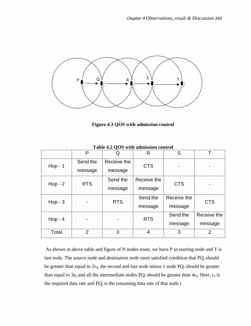
Chapter 4 Observations, result & Discussion 169
Figure 4.3 QOS with admission control
Table 4.2 QOS with admission controlP Q R S T
Hop - 1Send the
message
Receive the
messageCTS - -
Hop - 2 RTSSend the
message
Receive the
messageCTS -
Hop - 3 - RTSSend the
message
Receive the
messageCTS
Hop - 4 - - RTSSend the
message
Receive the
message
Total 2 3 4 3 2
As shown in above table and figure of N nodes route, we have P as starting node and T is
last node. The source node and destination node must satisfied condition that PQi should
be greater than equal to 2rd, the second and last node minus 1 node PQi should be greater
than equal to 3rd and all the intermediate nodes PQi should be greater than 4rd. Here, rd is
the required data rate and PQi is the remaining data rate of that node i.
P Q R S T
Chapter 4 Observations, result & Discussion 170
With the help of above example we are trying to explain the role of data rate
means how data rate of a node help in transmitting data through channel. As shown in
figure 4.3 and table 4.2 we have taken four different hops routes and node P is source
node and node T is destination node. Data will be flow from node P to node T, Channel is
shared by pair of node like node P and node Q shared the same channel in this adjacent
node are sharing the same channel. Data will start flow from node P and node P to node
Q and then node Q will transmit the data to next node and send message Request to Send
to node P, In this way node P will act two times first will sending the data and second
will receiving the message from node Q, As a result since node P has acted twice so he
must have twice the Data Rate so that traffic will work smoothly. From table 4.2 it is
clear indicate the role of each node in a particular hop. For example when node P act as
sender then node Q act as receiver and at same time send message to next node to check
the status of that node. In Hop – 1 node P act as sender and in Hop – 2 node Q act as
sender this process continue till we reach destination. Node uses two types of message to
check the status they are as RTS: Request to Send, CTS: Clear to Send. These two
message are also moving as the source node is keep on changing. Current node will send
Request to Send to previous node since its act as acknowledgment and send message
Clear to Send to next node where he want to send data.
4.4 Simulations of Routing Protocols(AODV, qAODV)
4.4.1. Simulation environment
We are using NS 2.29 as simulation tool. We installed the NS 2.29 on our
personal laptop having configuration as mention below. An Intel core (TM) 2 duo /1.83
GHz individual processor (PC) with Microsoft Windows XP Professional operation
system with service pack 3. The central processing unit has 2 GB of RAM (Random
Access Memory). The above said configuration has been taken from our system
properties as shown in below figure 4.4.

Chapter 4 Observations, result & Discussion 171
Figure 4.4 System general properties.
While simulating the routing protocols we emphasized on various parameters
used during simulation. They are as follows.
#set opt(chan) Channel/WirelessChannel
#set opt(prop) Propagation/TwoRayGround
#set opt(netif) NetIf/SharedMedia
set opt(netif) Phy/WirelessPhy
#set opt(mac) Mac/802_11
set opt(mac) Mac/802_11
#set opt(ifq) Queue/DropTail/PriQueue ;# for AODV
set opt(ifq) CMUPriQueue ;# for qAODV
set opt(ll) LL
set opt(x) 1000
set opt(y) 1000
set opt(ifqlen) 60
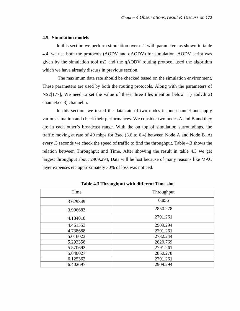
Chapter 4 Observations, result & Discussion 172
4.5. Simulation models
In this section we perform simulation over ns2 with parameters as shown in table
4.4. we use both the protocols (AODV and qAODV) for simulation. AODV script was
given by the simulation tool ns2 and the qAODV routing protocol used the algorithm
which we have already discuss in previous section.
The maximum data rate should be checked based on the simulation environment.
These parameters are used by both the routing protocols. Along with the parameters of
NS2[177], We need to set the value of these three files mention below 1) aodv.h 2)
channel.cc 3) channel.h.
In this section, we tested the data rate of two nodes in one channel and apply
various situation and check their performances. We consider two nodes A and B and they
are in each other’s broadcast range. With the on top of simulation surroundings, the
traffic moving at rate of 40 mbps for 3sec (3.6 to 6.4) between Node A and Node B. At
every .3 seconds we check the speed of traffic to find the throughput. Table 4.3 shows the
relation between Throughput and Time. After showing the result in table 4.3 we get
largest throughput about 2909.294, Data will be lost because of many reasons like MAC
layer expenses etc approximately 30% of loss was noticed.
Table 4.3 Throughput with different Time slot
Time Throughput
3.629349 0.856
3.906683 2850.278
4.184018 2791.261
4.461353 2909.2944.738688 2791.2615.016023 2732.2445.293358 2820.7695.570693 2791.2615.848027 2850.2786.125362 2791.2616.402697 2909.294
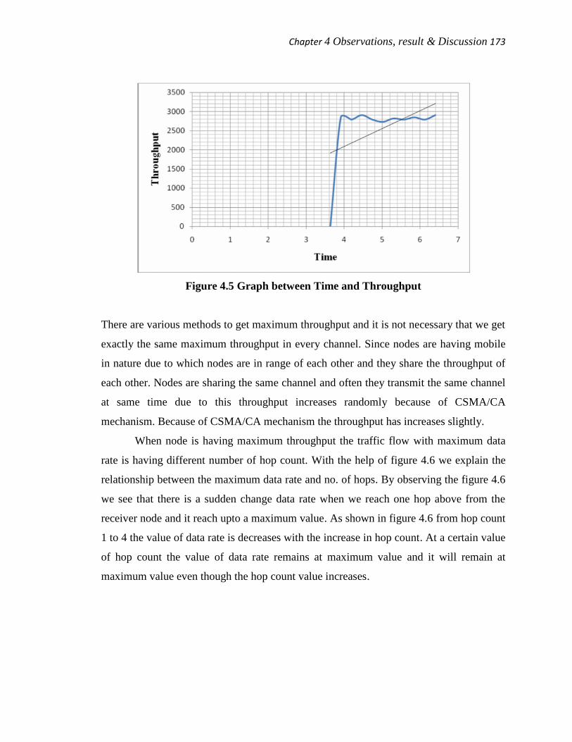
Chapter 4 Observations, result & Discussion 173
Figure 4.5 Graph between Time and Throughput
There are various methods to get maximum throughput and it is not necessary that we get
exactly the same maximum throughput in every channel. Since nodes are having mobile
in nature due to which nodes are in range of each other and they share the throughput of
each other. Nodes are sharing the same channel and often they transmit the same channel
at same time due to this throughput increases randomly because of CSMA/CA
mechanism. Because of CSMA/CA mechanism the throughput has increases slightly.
When node is having maximum throughput the traffic flow with maximum data
rate is having different number of hop count. With the help of figure 4.6 we explain the
relationship between the maximum data rate and no. of hops. By observing the figure 4.6
we see that there is a sudden change data rate when we reach one hop above from the
receiver node and it reach upto a maximum value. As shown in figure 4.6 from hop count
1 to 4 the value of data rate is decreases with the increase in hop count. At a certain value
of hop count the value of data rate remains at maximum value and it will remain at
maximum value even though the hop count value increases.
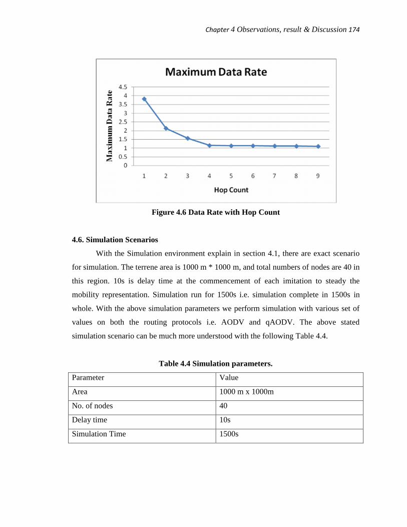
Chapter 4 Observations, result & Discussion 174
Figure 4.6 Data Rate with Hop Count
4.6. Simulation Scenarios
With the Simulation environment explain in section 4.1, there are exact scenario
for simulation. The terrene area is 1000 m * 1000 m, and total numbers of nodes are 40 in
this region. 10s is delay time at the commencement of each imitation to steady the
mobility representation. Simulation run for 1500s i.e. simulation complete in 1500s in
whole. With the above simulation parameters we perform simulation with various set of
values on both the routing protocols i.e. AODV and qAODV. The above stated
simulation scenario can be much more understood with the following Table 4.4.
Table 4.4 Simulation parameters.
Parameter Value
Area 1000 m x 1000m
No. of nodes 40
Delay time 10s
Simulation Time 1500s
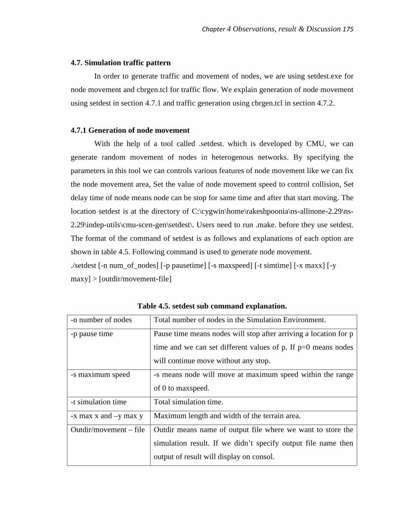
Chapter 4 Observations, result & Discussion 175
4.7. Simulation traffic pattern
In order to generate traffic and movement of nodes, we are using setdest.exe for
node movement and cbrgen.tcl for traffic flow. We explain generation of node movement
using setdest in section 4.7.1 and traffic generation using cbrgen.tcl in section 4.7.2.
4.7.1 Generation of node movement
With the help of a tool called .setdest. which is developed by CMU, we can
generate random movement of nodes in heterogenous networks. By specifying the
parameters in this tool we can controls various features of node movement like we can fix
the node movement area, Set the value of node movement speed to control collision, Set
delay time of node means node can be stop for same time and after that start moving. The
location setdest is at the directory of C:\cygwin\home\rakeshpoonia\ns-allinone-2.29\ns-
2.29\indep-utils\cmu-scen-gen\setdest\. Users need to run .make. before they use setdest.
The format of the command of setdest is as follows and explanations of each option are
shown in table 4.5. Following command is used to generate node movement.
./setdest [-n num_of_nodes] [-p pausetime] [-s maxspeed] [-t simtime] [-x maxx] [-y
maxy] > [outdir/movement-file]
Table 4.5. setdest sub command explanation.
-n number of nodes Total number of nodes in the Simulation Environment.
-p pause time Pause time means nodes will stop after arriving a location for p
time and we can set different values of p. If p=0 means nodes
will continue move without any stop.
-s maximum speed -s means node will move at maximum speed within the range
of 0 to maxspeed.
-t simulation time Total simulation time.
-x max x and –y max y Maximum length and width of the terrain area.
Outdir/movement – file Outdir means name of output file where we want to store the
simulation result. If we didn’t specify output file name then
output of result will display on consol.

Chapter 4 Observations, result & Discussion 176
As shown in figure 4.7 simulation result shows that there are 40 nodes and total
Destination Unreachable are 7104, total Route Changes are 232849 and total Link
Changes are 25079. It is not necessary that we always get the same set of result because
there are various factors that affect the simulation result, like system configuration,
network simulator version, different traffic pattern, different route selection and different
pair of nodes work as intermediate nodes. In figure 4.8 we shown the intermediate result
of .setdest command.
Figure 4.7 simulation result after execution of ./setdest command.
4.7.2. Traffic generation
We know that node movement is generated using setdest similarly we can
generate random flows of traffic, for this we use a Tcl script called “cbrgen” can be used.
With the help of this script we can generate the traffic load. This script locates in the
directory of C:\cygwin\home\rakeshpoonia\ns-allinone-2.29\ns-2.29\indep-utils\cmu-
scen-gen. The file name is cbrgen.tcl. To execute/run any script file we need to use ns
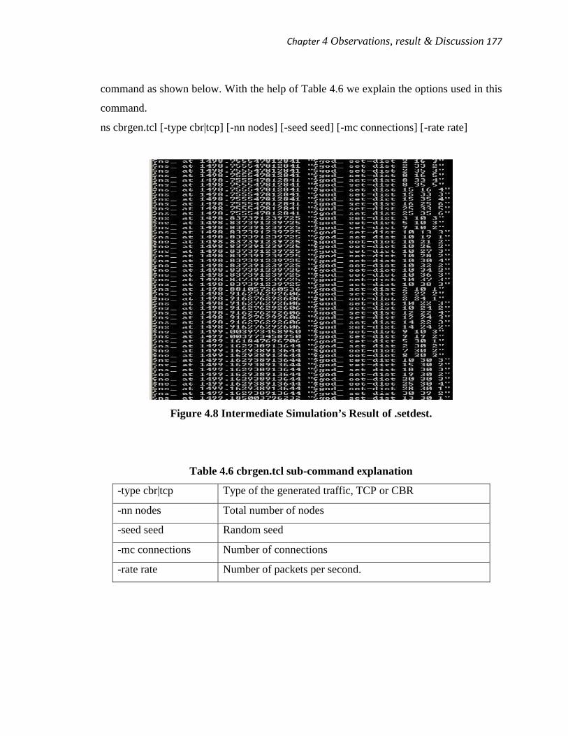
Chapter 4 Observations, result & Discussion 177
command as shown below. With the help of Table 4.6 we explain the options used in this
command.
ns cbrgen.tcl [-type cbr|tcp] [-nn nodes] [-seed seed] [-mc connections] [-rate rate]
Figure 4.8 Intermediate Simulation’s Result of .setdest.
Table 4.6 cbrgen.tcl sub-command explanation
-type cbr|tcp Type of the generated traffic, TCP or CBR
-nn nodes Total number of nodes
-seed seed Random seed
-mc connections Number of connections
-rate rate Number of packets per second.
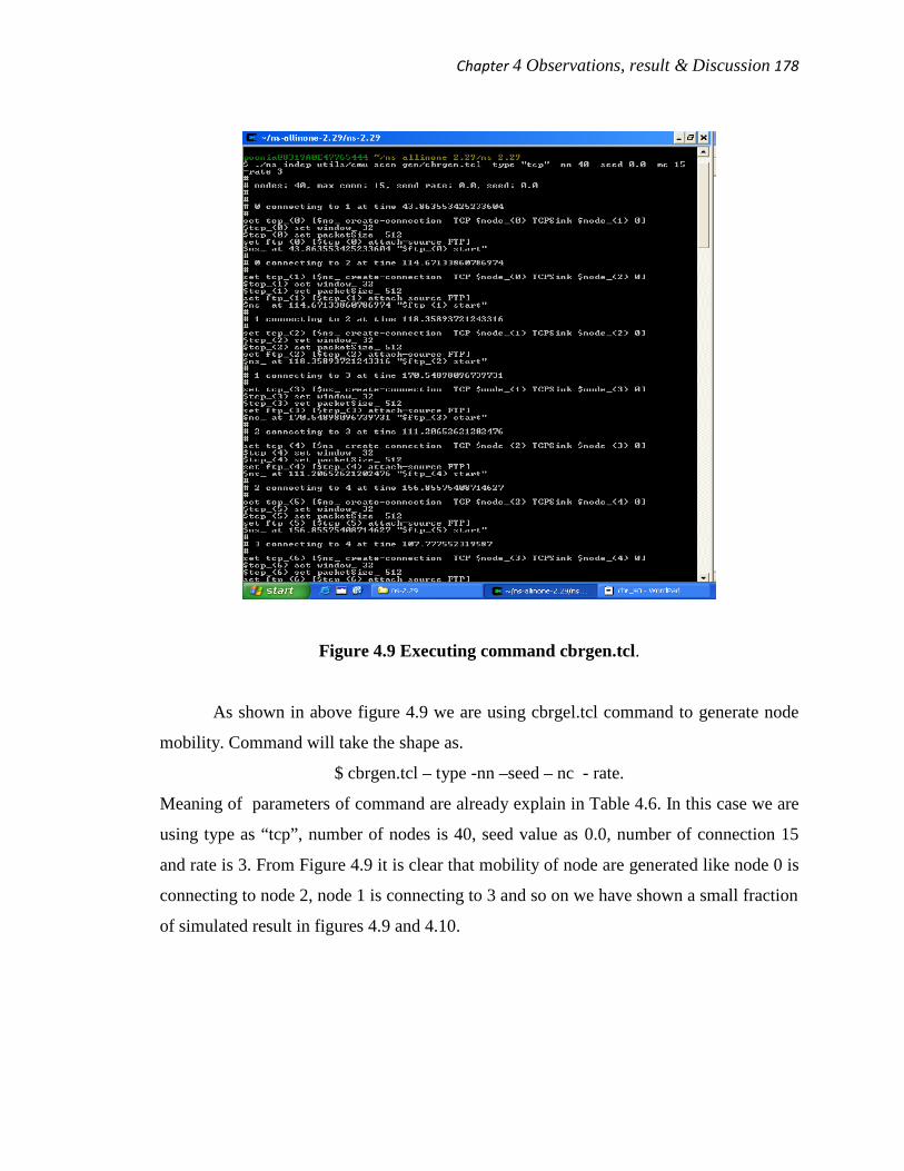
Chapter 4 Observations, result & Discussion 178
Figure 4.9 Executing command cbrgen.tcl.
As shown in above figure 4.9 we are using cbrgel.tcl command to generate node
mobility. Command will take the shape as.
$ cbrgen.tcl – type -nn –seed – nc - rate.
Meaning of parameters of command are already explain in Table 4.6. In this case we are
using type as “tcp”, number of nodes is 40, seed value as 0.0, number of connection 15
and rate is 3. From Figure 4.9 it is clear that mobility of node are generated like node 0 is
connecting to node 2, node 1 is connecting to 3 and so on we have shown a small fraction
of simulated result in figures 4.9 and 4.10.
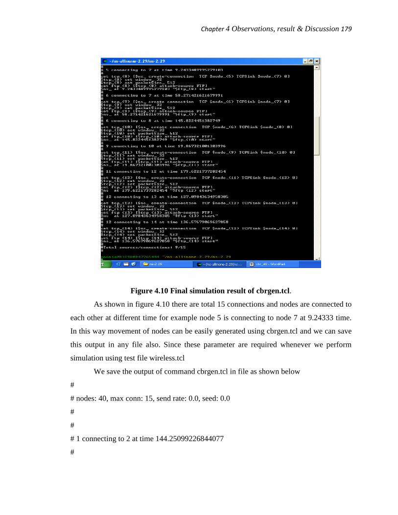
Chapter 4 Observations, result & Discussion 179
Figure 4.10 Final simulation result of cbrgen.tcl.
As shown in figure 4.10 there are total 15 connections and nodes are connected to
each other at different time for example node 5 is connecting to node 7 at 9.24333 time.
In this way movement of nodes can be easily generated using cbrgen.tcl and we can save
this output in any file also. Since these parameter are required whenever we perform
simulation using test file wireless.tcl
We save the output of command cbrgen.tcl in file as shown below
#
# nodes: 40, max conn: 15, send rate: 0.0, seed: 0.0
#
#
# 1 connecting to 2 at time 144.25099226844077
#
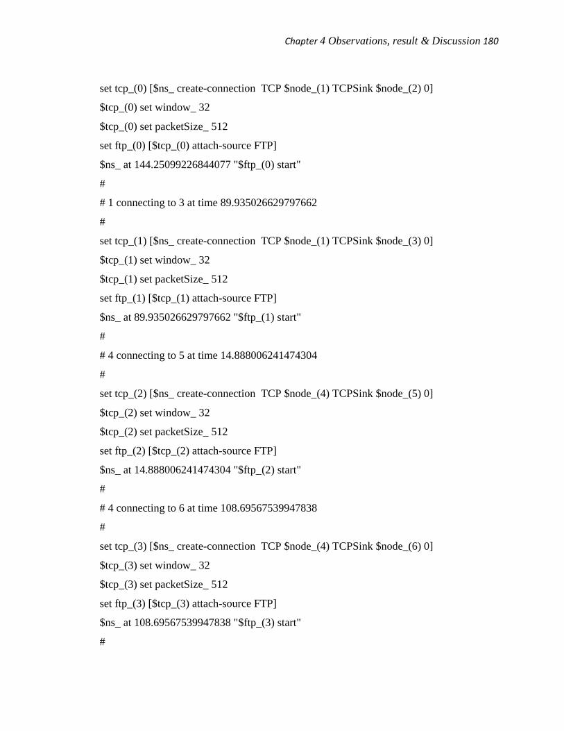
Chapter 4 Observations, result & Discussion 180
set tcp_(0) [$ns_ create-connection TCP $node_(1) TCPSink $node_(2) 0]
$tcp_(0) set window_ 32
$tcp_(0) set packetSize_ 512
set ftp_(0) [$tcp_(0) attach-source FTP]
$ns_ at 144.25099226844077 "$ftp_(0) start"
#
# 1 connecting to 3 at time 89.935026629797662
#
set tcp_(1) [$ns_ create-connection TCP $node_(1) TCPSink $node_(3) 0]
$tcp_(1) set window_ 32
$tcp_(1) set packetSize_ 512
set ftp_(1) [$tcp_(1) attach-source FTP]
$ns_ at 89.935026629797662 "$ftp_(1) start"
#
# 4 connecting to 5 at time 14.888006241474304
#
set tcp_(2) [$ns_ create-connection TCP $node_(4) TCPSink $node_(5) 0]
$tcp_(2) set window_ 32
$tcp_(2) set packetSize_ 512
set ftp_(2) [$tcp_(2) attach-source FTP]
$ns_ at 14.888006241474304 "$ftp_(2) start"
#
# 4 connecting to 6 at time 108.69567539947838
#
set tcp_(3) [$ns_ create-connection TCP $node_(4) TCPSink $node_(6) 0]
$tcp_(3) set window_ 32
$tcp_(3) set packetSize_ 512
set ftp_(3) [$tcp_(3) attach-source FTP]
$ns_ at 108.69567539947838 "$ftp_(3) start"
#
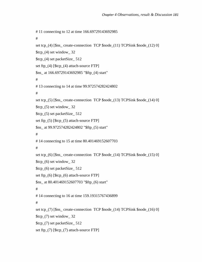
Chapter 4 Observations, result & Discussion 181
# 11 connecting to 12 at time 166.69729143692985
#
set tcp_(4) [$ns_ create-connection TCP $node_(11) TCPSink $node_(12) 0]
$tcp_(4) set window_ 32
$tcp_(4) set packetSize_ 512
set ftp_(4) [$tcp_(4) attach-source FTP]
$ns_ at 166.69729143692985 "$ftp_(4) start"
#
# 13 connecting to 14 at time 99.972574282424802
#
set tcp_(5) [$ns_ create-connection TCP $node_(13) TCPSink $node_(14) 0]
$tcp_(5) set window_ 32
$tcp_(5) set packetSize_ 512
set ftp_(5) [$tcp_(5) attach-source FTP]
$ns_ at 99.972574282424802 "$ftp_(5) start"
#
# 14 connecting to 15 at time 80.401469152607703
#
set tcp_(6) [$ns_ create-connection TCP $node_(14) TCPSink $node_(15) 0]
$tcp_(6) set window_ 32
$tcp_(6) set packetSize_ 512
set ftp_(6) [$tcp_(6) attach-source FTP]
$ns_ at 80.401469152607703 "$ftp_(6) start"
#
# 14 connecting to 16 at time 159.19315767436899
#
set tcp_(7) [$ns_ create-connection TCP $node_(14) TCPSink $node_(16) 0]
$tcp_(7) set window_ 32
$tcp_(7) set packetSize_ 512
set ftp_(7) [$tcp_(7) attach-source FTP]

Chapter 4 Observations, result & Discussion 182
$ns_ at 159.19315767436899 "$ftp_(7) start"
#
# 16 connecting to 17 at time 115.49036881676427
#
set tcp_(8) [$ns_ create-connection TCP $node_(16) TCPSink $node_(17) 0]
$tcp_(8) set window_ 32
$tcp_(8) set packetSize_ 512
set ftp_(8) [$tcp_(8) attach-source FTP]
$ns_ at 115.49036881676427 "$ftp_(8) start"
#
# 17 connecting to 18 at time 86.12521300377567
#
set tcp_(9) [$ns_ create-connection TCP $node_(17) TCPSink $node_(18) 0]
$tcp_(9) set window_ 32
$tcp_(9) set packetSize_ 512
set ftp_(9) [$tcp_(9) attach-source FTP]
$ns_ at 86.12521300377567 "$ftp_(9) start"
#
# 21 connecting to 22 at time 141.57900255246972
#
set tcp_(10) [$ns_ create-connection TCP $node_(21) TCPSink $node_(22) 0]
$tcp_(10) set window_ 32
$tcp_(10) set packetSize_ 512
set ftp_(10) [$tcp_(10) attach-source FTP]
$ns_ at 141.57900255246972 "$ftp_(10) start"
#
# 21 connecting to 23 at time 150.44340906219716
#
set tcp_(11) [$ns_ create-connection TCP $node_(21) TCPSink $node_(23) 0]
$tcp_(11) set window_ 32

Chapter 4 Observations, result & Discussion 183
$tcp_(11) set packetSize_ 512
set ftp_(11) [$tcp_(11) attach-source FTP]
$ns_ at 150.44340906219716 "$ftp_(11) start"
#
# 23 connecting to 24 at time 35.64782013913981
#
set tcp_(12) [$ns_ create-connection TCP $node_(23) TCPSink $node_(24) 0]
$tcp_(12) set window_ 32
$tcp_(12) set packetSize_ 512
set ftp_(12) [$tcp_(12) attach-source FTP]
$ns_ at 35.64782013913981 "$ftp_(12) start"
#
# 25 connecting to 26 at time 117.73622978373255
#
set tcp_(13) [$ns_ create-connection TCP $node_(25) TCPSink $node_(26) 0]
$tcp_(13) set window_ 32
$tcp_(13) set packetSize_ 512
set ftp_(13) [$tcp_(13) attach-source FTP]
$ns_ at 117.73622978373255 "$ftp_(13) start"
#
# 25 connecting to 27 at time 43.222650393481672
#
set tcp_(14) [$ns_ create-connection TCP $node_(25) TCPSink $node_(27) 0]
$tcp_(14) set window_ 32
$tcp_(14) set packetSize_ 512
set ftp_(14) [$tcp_(14) attach-source FTP]
$ns_ at 43.222650393481672 "$ftp_(14) start"
#
#Total sources/connections: 10/15
#