Embed Size (px)
Citation preview

Chapter 9 Homework Solution Chapter 9(1): P9.2-1, 5, 9 P9.3-2, 4 P9.4-1, 3 P9.5-2, 3, 4 P9.6-1, 2, 5 Chapter 9(2): P9.7-1, 2 P9.8-2, 4, 9, 15, 17 P9.9-1 P 9.2-1 Find the differential equation for the circuit shown in Figure P 9.2-1 using the direct method.
Figure P 9.2-1

P 9.2-5 The input to the circuit shown in Figure P 9.2-5 is the voltage of the voltage source, vs. The output is the capacitor voltage v(t). Represent the circuit by a second-order differential equation that shows how the output of this circuit is related to the input, for t > 0. Hint: Use the direct method.
Figure P 9.2-5
Solution: After the switch closes, use KCL to get
( ) ( ) ( )2
v t di t C v tR dt
= +
Use KVL to get
( ) ( ) ( )s 1dv R i t L i t v tdt
= + +
Substitute to get
( ) ( ) ( ) ( ) ( )
( ) ( ) ( )
21
s 1 22 2
21 2
122 2
R d L d dv v t R C v t v t CL v t v tR dt R dt dt
R Rd L dCL v t R C v t v tdt R dt R CL
= + + + +
+= + + +
Finally,
( ) ( ) ( )2
s 1 1 22
2 2
1v R R Rd dv t v t v tCL dt L R C dt R CL
+= + + +
P 9.2-9 The input to the circuit shown in Figure P 9.2-9 is the voltage of the voltage source, vs. The output is the capacitor voltage v(t). Represent the circuit by a second-order differential equation that shows how the output of this circuit is related to the input, for t > 0. Hint: Use the direct method.
Figure P 9.2-9
Solution: After the switch closes
( ) ( )di t C v tdt
=
KCL and KVL give
( ) ( ) ( ) ( ) ( )s 21
1 d dv R i t L i t v t L i t v tR dt dt
= + + + +
Substituting gives
( ) ( ) ( )
( ) ( ) ( )
22 2
s 221 1
22 2
221 1
1 1
1 1
R Rd dv LC v t R C v t v tR dt dt R
R Rd dLC v t R C v t v tR dt dt R
= + + + +
= + + + +
Finally
( ) ( ) ( ) ( ) ( )2
1 s 1 2
1 2 1 2
1R v R Rd dv t v t v tdt dt LCLC R R L R R
= + ++ +
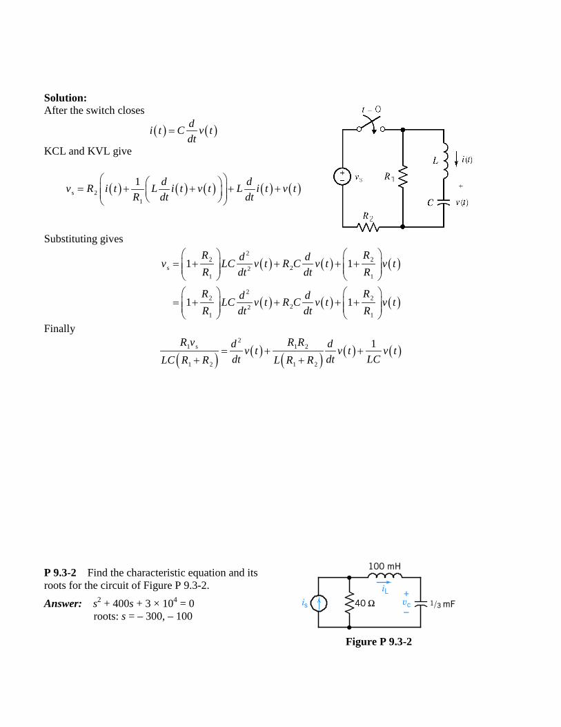
P 9.3-2 Find the characteristic equation and its roots for the circuit of Figure P 9.3-2. Answer: s2 + 400s + 3 × 104 = 0
roots: s = – 300, – 100
Figure P 9.3-2
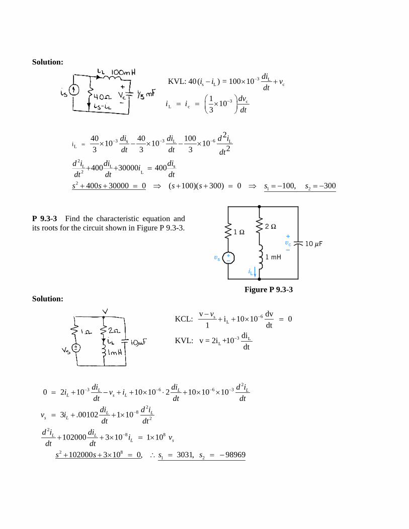
Solution: P 9.3-3 Find the characteristic equation and its roots for the circuit shown in Figure P 9.3-3.
Figure P 9.3-3
Solution:
3 Ls L c
3 cL c
KVL: 40( ) = 100 10
1 103
dii i vdt
dvi idt
−
−
− × +
= = ×
3 3 6L LL
2L L2 L
21 2
s
s
i 240 40 10010 10 10 23 3 3
400 30000 400
400 30000 0 ( 100)( 300) 0 100, 300
di di d idt dt dt
did i di idt dt dts s s s s s
− − −= × − × − ×
+ + =
+ + = ⇒ + + = ⇒ = − = −
6sL
3 LL
v dvKCL: i 10 10 01 dt
diKVL: v = 2i +10dt
v −
−
−+ + × =
23 6 6 3
28
2
28 8
2 81 2
0 2 10 10 10 2 10 10 10
3 .00102 1 10
102000 3 10 1 10
102000 3 10 0, 3031, 98969
L L LL s L
L Ls L
L LL s
di di d ii v idt dt dt
di d iv idt dt
d i di i vdt dt
s s s s
− − − −
−
−
= + − + + × ⋅ + × ×
= + + ×
+ + × = ×
+ + × = ∴ = = −
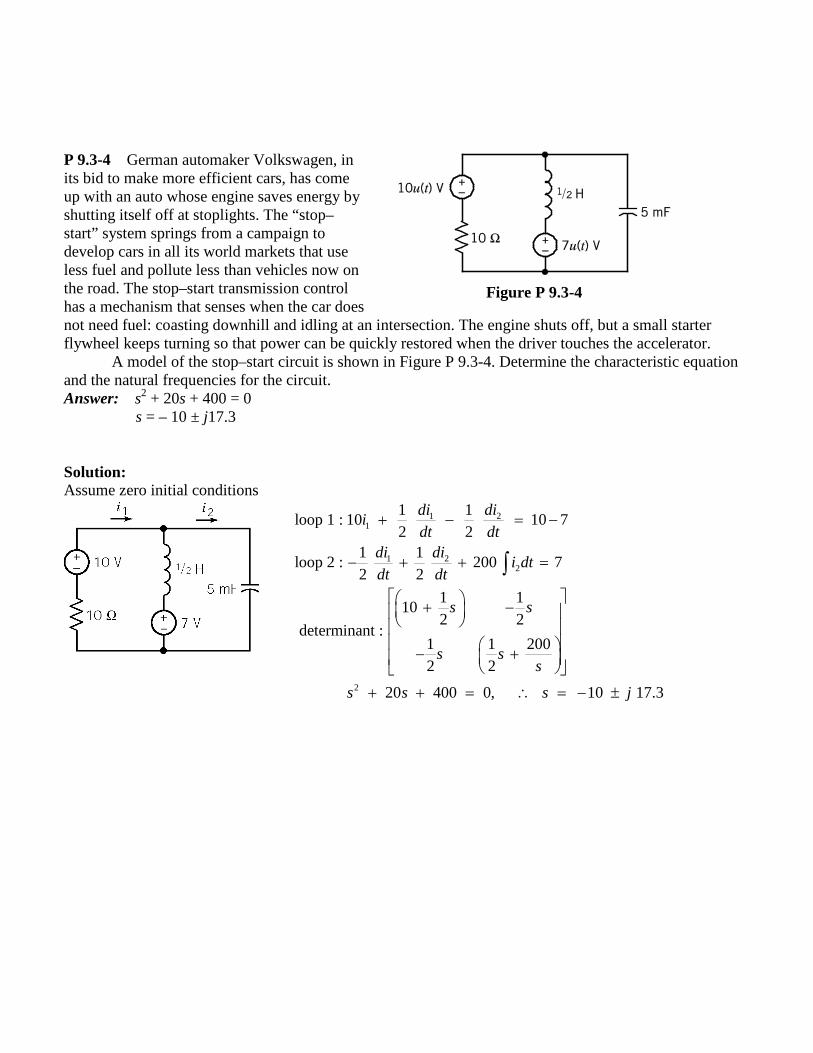
P 9.3-4 German automaker Volkswagen, in its bid to make more efficient cars, has come up with an auto whose engine saves energy by shutting itself off at stoplights. The “stop–start” system springs from a campaign to develop cars in all its world markets that use less fuel and pollute less than vehicles now on the road. The stop–start transmission control has a mechanism that senses when the car does
Figure P 9.3-4
not need fuel: coasting downhill and idling at an intersection. The engine shuts off, but a small starter flywheel keeps turning so that power can be quickly restored when the driver touches the accelerator.
A model of the stop–start circuit is shown in Figure P 9.3-4. Determine the characteristic equation and the natural frequencies for the circuit. Answer: s2 + 20s + 400 = 0
s = – 10 ± j17.3 Solution: Assume zero initial conditions
1 21
1 22
2
1 1loop 1 : 10 10 72 2
1 1loop 2 : 200 72 2
1 110 2 2
determinant : 1 1 200 2 2
20 400 0, 10 17.3
di diidt dt
di di i dtdt dt
s s
s ss
s s s j
+ − = −
− + + =
+ − − +
+ + = ∴ = − ±
∫
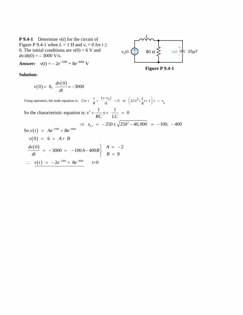
P 9.4-1 Determine v(t) for the circuit of Figure P 9.4-1 when L = 1 H and vs = 0 for t ≥ 0. The initial conditions are v(0) = 6 V and dv/dt(0) = – 3000 V/s. Answer: v(t) = – 2e–100t + 8e–400t V
Figure P 9.4-1
Solution:
( ) ( )00 6, 3000
dvv
dt= = −
( ) 2Using operators, the node equation is: 0 1 v vv LsCsv or LCs s v vsR sL R− + + = + + =
2
21,2
1 1So the characteristic equation is: 0
250 250 40,000 100, 400
s sRC LC
s
+ + =
⇒ = − ± − = − − ( )( )( )
( )
100 400
100 400
So
0 6
20 3000 100 400
8
2 8 t>0
t t
t t
v t Ae Be
v A B
AdvA B
Bdt
v t e e
− −
− −
= +
= = +
= −= − = − − =
∴ = − +
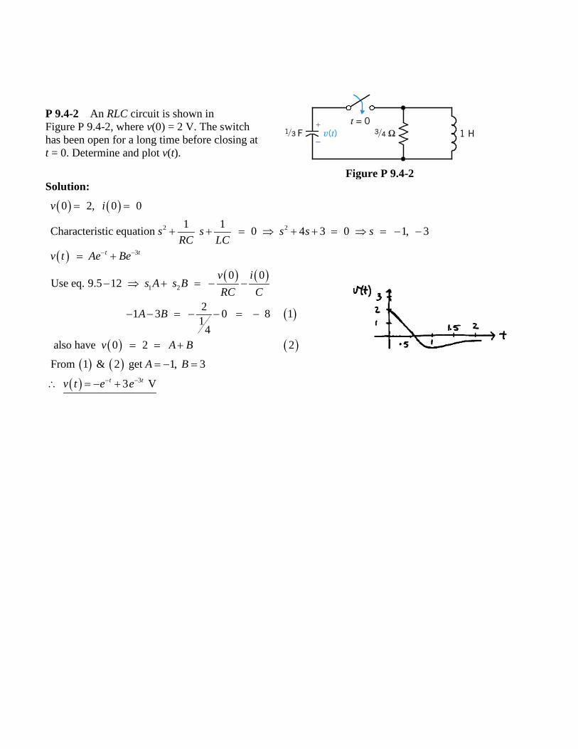
P 9.4-2 An RLC circuit is shown in Figure P 9.4-2, where v(0) = 2 V. The switch has been open for a long time before closing at t = 0. Determine and plot v(t).
Figure P 9.4-2
Solution:
( ) ( )
( )( ) ( )
( )
( ) ( )( ) ( )
2 2
3
1 2
0 2, 0 01 1Characteristic equation 0 4 3 0 1, 3
0 0Use eq. 9.5 12
21 3 0 8 114
also have 0 2 2
From 1 & 2 get 1
t t
v i
s s s s sRC LC
v t Ae Be
v is A s B
RC C
A B
v A B
A
− −
= =
+ + = ⇒ + + = ⇒ = − −
= +
− ⇒ + = − −
− − = − − = −
= = +
= −
( ) 3
, 3
3 Vt t
B
v t e e− −
=
∴ = − +
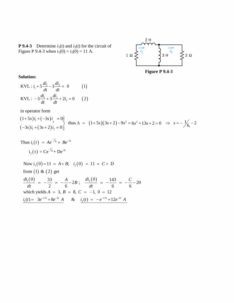
P 9.4-3 Determine i1(t) and i2(t) for the circuit of Figure P 9.4-3 when i1(0) = i2(0) = 11 A.
Figure P 9.4-3
Solution:
( ) ( )( ) ( )
( )( )1 2 22
1 2
in operator form
1 5 3 0 1 thus 1 5 3 2 9 26 13 2 0 6,3 3 2 0
s i s is s s ss s
s i s i
+ + − = ∆ = + + − = + ⇒ = − −+ =− + + =
( ) ( )( ) ( )
( ) ( )
1 2
1 2
/6 2 /6 21 2
Now i 0 11 ; 0 11
from 1 & 2 get
0 033 143 2 ; 202 6 6 6
which yields 3, 8, 1, 0 12( ) 3 8 & ( ) 12 t t t t
A B i C D
di diA CBdt dt
A B Ci t e e A i t e e A− − − −
= = + = = +
= − = − − = − = − −
= = = − =
= + = − +
( )
( )
1 21
1 22
KVL : 5 3 0 1
KVL : 3 3 2 0 2
di diidt dt
di di idt dt
+ − =
− + + =
( )
( )
261
t- -2t62
Thus
i t = Ce + De
t ti t Ae Be− −= +

P 9.5-2 Find vc(t) for t > 0 for the circuit of Figure P 9.5-2. Assume steady-state conditions exist at t = 0–. Answer: vc(t) = – 8te–2t V
Figure P 9.5-2
Solution:
0t > ( ) cc c c
2
c
1KCL at v : 04
4 4 0
t
c c
dvv dt vdt
d v dv vdt dt
−∞ + + =∫
⇒ + + =
( )2 2 2c 1 24 4 0, 2, 2 t ts s s v t A e A t e− −+ + = = − − ⇒ = +
0 (Steady-State)t −= ( ) ( ) ( ) ( )
( ) ( ) ( )( ) ( )
200 0 0 & 0 2 010
Since 0 0 then 0 0 2
0 0 V 8 S14
c c L L
c c L
c c
Vv v i A i
v i i A
dv idt
− + − +
+ + +
+ +
= = = = =Ω
= = − = −
∴ = = −
( )( )
( )
1
2
2
So 0 0
0 8
8
c
c
tc
v A
dvA
dtv t te V
+
+
−
= =
= − =
∴ = −

P 9.5-3 Police often use stun guns to incapacitate potentially dangerous felons. The hand-held device provides a series of high-voltage, low-current pulses. The power of the pulses is far below lethal levels, but it is enough to cause muscles to contract and put the person out of action. The device provides a pulse of up to 50,000 V, and a current of 1 mA
Figure P 9.5-3
flows through an arc. A model of the circuit for one period is shown in Figure P 9.5-3. Find v(t) for 0 < t < 1 ms. The resistor R represents the spark gap. Select C so that the response is critically damped. Solution:
( ) ( )4Assume steady state at 0 0 10 V & 0 0c Lt v i− − −− = ∴ = =
0t > ( )
( )
6
26
2
KVL a: .01 10 0 1
Also : .01 10 2
Lc L
L LcL
div idt
d i didvi C Cdt dt dt
− + + =
= − = − +
( ) ( )( )
( )
26
2
26 62 6
12 2
7 7
75 10 51 2
0.01 10 0
10 10 4 .01Characteristic eq. 0.01 10 1 0
2 .01
for critically damped: 10 C .04C = 0 0.04 pF 5 10 , 5 10
So
L LL
tL
d i diC C idt dt
C C CC s s s
C
C s
i t A e A te− × − ×
∴ + + =
− ± −⇒ + + = ⇒ =
−
⇒ = ∴ = − × − ×
= +
( ) ( ) ( )
( ) ( ) ( )
( ) ( )
7
7
710
6 6
6 6 5 10L 1 2
6 12 5 10
Now from (1) 0 100 0 10 0 10
0So i 0 0 and 10 10 A
Now 10 10 V
t
Lc L
L tL
tL
di Av i sdtdi
A A i t tedt
v t i t te
+ + +
− ×
− ×
⇒ = − =
= = = = ∴ =
= =

P 9.5-4 Reconsider Problem P 9.4-1 when L = 640 mH and the other parameters and conditions remain the same. Answer: v(t) = (6 – 1500t)e – 250t V
Figure P 9.4-1 Solution:
2 31 1 1 10 with 500 and 62.5 10 yields 250, 250s s sRC LC RC LC
+ + = = = × = − −
( )( )( )
( )
250 250
250 250
0 6
03000 250 1500
6 1500
t t
t t
v t Ae Bte
v A
dvA B B
dtv t e te
− −
− −
= +
= =
= − = − + ⇒ = −
∴ = −
P 9.6-1 A communication system from a space station uses short pulses to control a robot operating in space. The transmitter circuit is modeled in Figure P 9.6-1. Find the output voltage vc(t) for t > 0. Assume steady-state conditions at t = 0–.
Answer: vc(t) = e– 400t [3 cos 300t + 4 sin 300t] V
Figure P 9.6-1

Solution: P 9.6-2 The switch of the circuit shown in Figure P 9.6-2 is opened at t = 0. Determine and plot v(t) when C = 1/4 F. Assume steady state at t = 0–. Answer: v(t) = – 4e–2t sin 2t V
Figure P 9.6-2
t > 0
( )
( )
6KCL at : 5 10 0 1250
also : 0.8 2
ccc L
Lc
dvvv idt
divdt
−+ + × =
=
( ) ( )
( )
25 2
2
1 2
Solving for i in 1 & plugging into 2L
400 cos300 sin300
800 2.5 10 0 800 250,000 0, 400 300c cc
tv t e A t A tc
d v dv v s s s jdt dt
− ∴ = +
+ + × = ⇒ + + = = − ±
t Steady State= −−0 ( )
( ) ( )( ) ( ) ( )
( ) ( ) ( ) ( )( )( )
( ) [ ]
5
1
1 2 2
400
6 V 60 A 0500500 60 250 6 3 V 0500
0Now from 1 : 2 10 0 800 0 0
So 0 3
0 0 400 300 4
3cos300 4sin 300
L L
c c
cL c
c
c
tc
i i
v v
dvi v
dtv A
dvA A A
dtv t e t t V
− +
− +
++ +
+
+
−
− −= = =Ω−= + = =
= − × − =
= =
= = − + ⇒ =
∴ = +

Solution:
0t −= ( )( )0 2 A
0 0
i
v
=
=
0t −=
( ) ( )0
KCL at node a:
1 0 0 11
tv dvC vdt idt L
+ + + =∫
( )2
1 1 12in operator form have 0 0 or 0
with 4 8 0 2 2
v Csv v i s s vLs C LC
s s s j
+ + + = + + =
+ + = ⇒ = − ± ( ) [ ]( )
( ) ( ) ( ) ( ) [ ]
( )
21 2
1
2 2
2
cos 2 sin 2
0 0
0 1From 1 , 0 0 4 2 8 2 4
So 4 sin 2 V
t
t
v t e B t B t
v B
dvi v B or B
dt Cv t e t
−
−
= +
= =
= − − = − = − = = −
= −
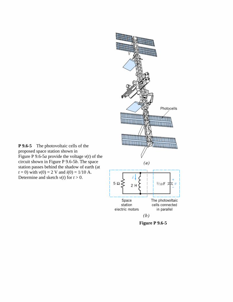
P 9.6-5 The photovoltaic cells of the proposed space station shown in Figure P 9.6-5a provide the voltage v(t) of the circuit shown in Figure P 9.6-5b. The space station passes behind the shadow of earth (at t = 0) with v(0) = 2 V and i(0) = 1/10 A. Determine and sketch v(t) for t > 0.
Figure P 9.6-5
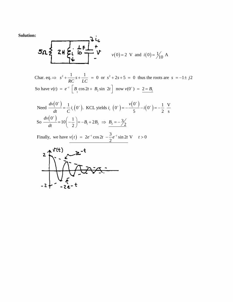
Solution:
( ) ( ) 10 2 V and 0 A10v i= =
2 21 1Char. eq. 0 or 2 5 0 thus the roots are 1 2s s s s s jRC LC
⇒ + + = + + = = − ±
2 11So have ( ) cos 2 sin 2 now (0 ) 2tv t e B t B t v B− + = + = =
( ) ( ) ( ) ( ) ( )( )
1 2 2
0 01 1 VNeed 0 . KCL yields 0 0 5 2 s
0 1 3So 10 2 22
c c
dv vi i i
dt Cdv
B B Bdt
+ ++ + +
+
= = − − = −
= − = − + ⇒ = −
( ) 3Finally, we have 2 cos 2 sin 2 V 02
t tv t e t e t t− −= − >

P 9.7-1 Determine the forced response for the inductor current if when (a) is = 1 A, (b) is = 0.5t A, and (c) is = 2e–250t A for the circuit of Figure P 9.7-1.
Figure P 9.7-1
Solution:
KCL :
KVL :
s L
L
v dvi i CR dt
div Ldt
= + +
= 2
2 L Ls L
di d iLi i LCR dt dt
= + +
( )( )
2
2
53
( ) assume
1 1Let in
1to get: 0 0 1 1 10 .01 1 10
s f
L LL f L s
f
i l u t i A
d i dii i A i idt RC dt LC
A A i−−
= ∴ =
= = + + =
+ + = ⇒ = × =×
( ) ( ) ( ) ( )( )
0.5 ( ) assume 65 10 0.5
100 .001 .01 .001650 100000 0 and 100000 0.5
s fi t u t i At B
A At B t
A B At t
= ∴ = +
+ + + =
⇒ + = =
(a)
(b)
6
8
6 8
5 10 3.25 10
5 10 3.25 10f
ABi t A
−
−
− −
= ×
= ×
= × − × 250 250
250
2 Assumming does not work
because cannot have the same form as we choose
t ts f
tf s f
i e i Ae
i i i Bte
− −
−
= =
∴ = 250 250 250
250
250
250 2
150 2 0.0133
0.0133 A
t t tt
tf
Be Bte Bte eRC RC LC
BB
i te
− − −−
−
−+ + =
==
=
(c)

P 9.7-2 Determine the forced response for the capacitor voltage, vf, for the circuit of Figure P 9.7-2 when (a) vs = 2 V, (b) vs = 0.2t V, and (c) vs = 1e–30t V.
Figure P 9.7-2
Solution:
Represent the circuit by the differential equation: 2 1
sd v R dv v vdt L dt LC
+ + =
(a) 2 assume 1Then 0 0 12000 2 so 6000
s f
f
v v A
A A v
= ∴ =
+ + = = =
0.2 assume 70 12000 12000 0.2 70 12000 0 and 12000 0.2
s fv t v At BA At B t A B At t
= ∴ = +
+ + = ⇒ + = = (b)
1 70 , 35060000 12000
350 V60000f
AA B B
tv
= = ⇒ =
∴ = +
(c) 30 30
30 30 30 30 30
30
assume 1900 2100 12000 10800
10800
V10800
t ts f
t t t t t
t
f
v e v Ae
A Ae Ae e Ae e A
ev
− −
− − − − −
−
= ∴ =
− + = ⇒ = ⇒ =
=

P 9.8-2 Determine i(t) for t > 0 for the circuit shown in Figure P 9.8-2.
Hint: Show that 1 = 2
2 ( ) 5 ( ) 5 ( ) for 0d di t i t i t tdt dt
+ + >
Figure P 9.8-2
Answer: i(t) = 0.2 + 0.246 e–3.62t – 0.646 e–1.38t A for t > 0. Solution: First, find the steady state response for t < 0. The input is constant so the capacitor will act like an open circuit at steady state, and the inductor will act like a short circuit.
( ) 10 0.2 A1 4
i −= =
+
and
( ) ( )40 1 0.8 V1 4
v = − = −+
For t > 0 Apply KCL at node a:
s
1
0v V dC v iR dt−
+ + =
Apply KVL to the right mesh:
2 2 L0d dR i L i v v R i L idt dt
+ − = ⇒ = +
After some algebra: 2 2
1 2 1 2 s2 2
1 1 1
5 5 1L R R C R R Vd d d di i i i i i
dt R L C dt R L C R L C dt dt+ +
+ + = ⇒ + + =
The forced response will be a constant, if = B so 2
21 5 5 0.2 Ad dB B B Bdt dt
= + + ⇒ = .
To find the natural response, consider the characteristic equation:
( ) ( )20 5 5 3.62 1.38s s s s= + + = + +

The natural response is
n 1 23.62 1.38t ti A e A e− −= +
so ( ) 1 2
3.62 1.38 0.2t ti t A e A e− −= + + Then
( ) ( ) ( ) 1 23.62 1.384 4 10.48 1.52 0.8t tdv t i t i t A e A e
dt− − = + = − − +
At t=0+ ( ) 1 20.2 0 0.2i A A− = + = + +
( ) 1 20.8 0 10.48 1.52 0.8v A A− = + = − − + so A1 = 0.246 and A2 = -0.646. Finally
( ) 3.62 1.380.2 0.246 0.646 At ti t e e− −= + −

P 9.8-4 Find v(t) for t > 0 for the circuit shown in Figure P 9.8-4 when v(0) = 1 V and iL(0) = 0.
Answer: 3 4125 429 21cos 33 sin V
17t tv e e t t− − = − − +
Figure P 9.8-4
Solution:
t 0> ( )
( )
1KCL at top node : 0.5 5cos 0 112
1KVL at right loop : 0.5 212
LL
L
di dvt i dtdtdi dv vdt dt
− + + =
= +
( )
( ) ( )
2 2
2 2
2 2
2 2
1 of 1 0.5 5sin (3)12
1 of 2 0.5 412
L L
L
d i di d vd tdt dt dt dtd i d v dvd
dt dt dt dt
⇒ + + = −
⇒ = +
( ) ( ) ( )2
2
22
2
Solving for in 4 and in 2 & plugging into 3
7 12 30sin 7 12 0 3, 4
L Ld i didt dt
d v dv v t s s sdt dt
+ + = − ⇒ + + = ⇒ = − −
3 41 2 1 2
1 2
so ( ) Try cos sin & pluginto D.E., equating like terms
3321yields , 17 17
t tf fv t A e A e v v B t B t
B B
− −= + + = +
= = − 0t +=
( ) 5 1 (0 ) V20 2 241 s1 1 12c
dvi Adt
++ −= = ∴ = =
( )
1 21
2 1 2
3 4
21So (0 ) 1 2517 429(0 ) 33 24 3 4 1717
1 ( ) 25 429 21cos 33sin V17t t
v A A Adv AA A
dtv t e e t t
+
+
− −
= = + + = = −= = − − −
∴ = − − +
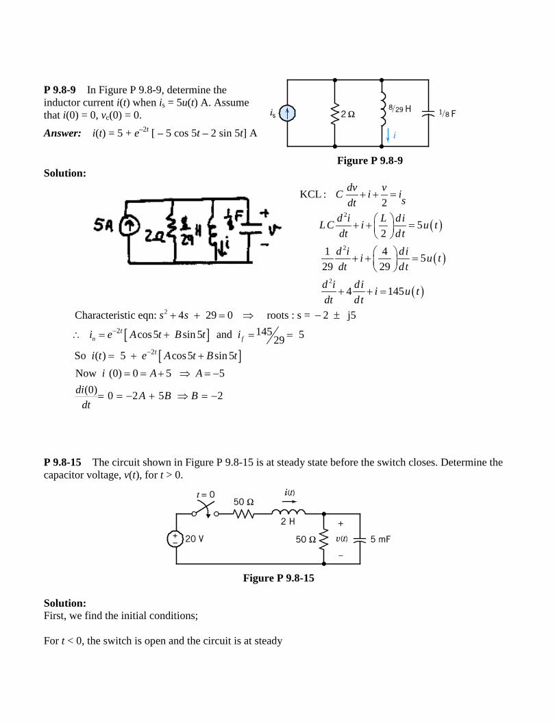
P 9.8-9 In Figure P 9.8-9, determine the inductor current i(t) when is = 5u(t) A. Assume that i(0) = 0, vc(0) = 0. Answer: i(t) = 5 + e–2t [ – 5 cos 5t – 2 sin 5t] A
Figure P 9.8-9 Solution: P 9.8-15 The circuit shown in Figure P 9.8-15 is at steady state before the switch closes. Determine the capacitor voltage, v(t), for t > 0.
Figure P 9.8-15
Solution: First, we find the initial conditions; For t < 0, the switch is open and the circuit is at steady
( )
( )
( )
2
2
2
KCL :2
52
1 4 529 29
4 145
dv vC i isdtd i L diLC i u tdt dt
d i dii u tdt dt
d i di i u tdt dt
+ + =
+ + =
+ + =
+ + =
[ ][ ]
2
2
2
Characteristic eqn: 4 29 0 roots : s = 2 j5145 cos5 sin 5 and 529
So ( ) 5 cos5 sin 5Now (0) 0 5 5
(0) 0 2 5 2
n ft
t
s s
i e A t B t i
i t e A t B ti A A
di A B Bdt
−
−
+ + = ⇒ − ±
∴ = + = =
= + +
= = + ⇒ = −
= = − + ⇒ = −

state. At steady state, the capacitor acts like an open circuit and the inductor acts like a short circuit.
( )0 0 Vv − = and ( )0 0 Ai − = also
( ) ( ) ( )0 00 0
0.005 50 0.005i vd v
dt= − =
×
Next, represent the circuit after the switch closes by a differential equation. After the switch closes, use KCL to get
( ) ( ) ( )2
v t di t C v tR dt
= +
Use KVL to get
( ) ( ) ( )s 1dv R i t L i t v tdt
= + +
Substitute to get
( ) ( ) ( ) ( ) ( )
( ) ( ) ( )
21
s 1 22 2
21 2
122 2
R d L d dv v t R C v t v t CL v t v tR dt R dt dt
R Rd L dCL v t R C v t v tdt R dt R
= + + + +
+= + + +
Finally,
( ) ( ) ( )2
s 1 1 22
2 2
1v R R Rd dv t v t v tCL dt L R C dt R CL
+= + + +
Compare to
( ) ( ) ( )2
202 2 ( )d di t i t i t f t
dtdtα ω+ + =
to get 1 1 2 s2
02 2
12 , and ( )R R R v
f tL R C R CL CL
α ω+
= + = =
With the given element values, we have 14.5α = and 2
0 200ω = . Consequently, the roots of the
characteristic equation are 1 11.3s = − and 2 17.7s = − so the circuit is overdamped. The natural response is

( ) 11.3 17.7n 1 2
t tv t A e A e− −= + Next, determine the forced response. The steady state response after the switch opens will be used as the forced response. At steady state, the capacitor acts like an open circuit and the inductor acts like a short circuit.
f s1 10 V2
v v= =
So
( ) 11.3 17.7n 1 210 t tv t A e A e− −= + +
It remains to evaluate A1 and A2 using the initial conditions. At t = 0 we have
( ) 1 20 0 10v A A= = + + and
( ) 1 20 0 11.3 17.7d v A Adt
= = − −
Solving these equations gives 1 227.6 and 17.6A A= − =
Finally,
( ) 11.3 17.710 27.6 17.6t tv t e e− −= − +

P 9.8-17 The circuit shown in Figure P 9.8-17 is at steady state before the switch opens. Determine the inductor current, i2(t), for t > 0.
Figure P 9.8-17
Solution: First, we find the initial conditions; For t < 0, the switch is closed and the circuit is at steady state. At steady state, the inductors act like short circuits.
( )1200 1.333 A15
i − = = and
( )2 0 0 Ai − =
Next, represent the circuit by a differential equation. After the switch opens, KVL gives
( ) ( ) ( )1 1 2 2 2 2d dL i t R i t L i tdt dt
= +
KVL and KCL give
( ) ( ) ( )( )1 1 1 1 2 0dL i t R i t i tdt
+ + =
Use the operator method to get
( )1 1 2 2 2 2
1 1 1 1 2 0
L s i R i L s i
L s i R i i
= +
+ + =

( ) ( )
21 1 1 1 1 2
12 2 2 2 2 2 2 2 1 2
1
2 1 222 2 2 1 1 2 2
1 1
2 1 1 1 222 2 2
2 2 1 1 2
0
0
0
0
L s i R s i R s i
Rs R i L s i R i L s i R s i
L
L R RL s i R R R s i i
L L
R R R R Rs i s i i
L L L L L
+ + =
+ + + + =
+ + + + =
+ + + + =
so
( ) ( ) ( )2
2 1 1 1 22 2 22
2 2 1 1 2
0R R R R Rd di t i t i t
dt L L L dt L L
+ + + + =
Compare to
( ) ( ) ( )2
202 2 ( )d di t i t i t f t
dtdtα ω+ + =
to get 2 1 1 1 22
02 2 1 1 2
2 , and ( ) 0R R R R R
f tL L L L L
α ω= + + = =
With the given element values, we have 33.9α = and 2
0 281.25ω = . Consequently, the roots of the
characteristic equation are 2 21,2 0 4.4, 63.4s α α ω= − ± − = − − so the circuit is overdamped. The natural
response is
( ) 4.4 63.4n 1 2
t ti t A e A e− −= + Next, determine the forced response. The steady state response after the switch opens will be used as the forced response. At steady state the inductors act like short circuits.
f 0 Ai =
So ( ) ( ) ( ) 4.4 63.4
2 n f 1 2t ti t i t i t A e A e− −= + = +
It remains to evaluate A1 and A2 using the initial conditions. At t = 0 we have

( )2 1 20 0i A A= = +
( ) ( ) ( ) ( ) ( )2 2 2 2 1 1 1 2 20 0 0 0 0 20d dL i R i R i R i idt dt
+ + + ⇒ = −
and
( ) 1 220 0 4.4 63.4d i A Adt
− = = − −
Solving these equations gives A1 = −0.339 and A2 = 0.339 so
( ) 4.4 63.42 0.339 0.339 for 0t ti t e e t− −= − + ≥

P 9.9-1 Find v(t) for t > 0 using the state variable method of Section 9.9 when C = 1/5 F in the circuit of Figure P 9.9-1. Sketch the response for v(t) for 0 < t < 10 s. Answer: v(t) = – 25e–t + e– 5t + 24 V
Figure P 9.9-1
Solution:
2
2Solving for i in (1) & plugging into (2) 6 5 1201 2
The characteristic equation is: 6 5 0,The roots of the characteristic equation are 1, 5
Tthe natural response is:
d v dv vdtdt
s ss
⇒ + + =
+ + == − −
∴ 5n 1 2
f f
L
1 21 2
51 2
( ) Try & plug into D.E. 24
(0) VFrom (1) 20 5 (0) 20 sSo (0) 0 24 25, 1
(0) ( ) 25 24 V 20 5
t t
t t
v t A e A ev B B v
dv idt
v A A A Adv v t e eA A
dt
− −
− −
= += ⇒ = =
= − =
= = + + = − = ∴ = − + += = − −
0 circuit is source free (0) 0 & (0) 0Lt i v−= ∴ = = t > 0
( )
L
LL
(1)1KCL at top node: 45
KVL at right loop: 1 6 0
dvi dt
div idt
+ =
− − =