Embed Size (px)
Citation preview
SOLIDWORKS 16 BatteRy HOLDeR aa BOat Page 9-1
Boat
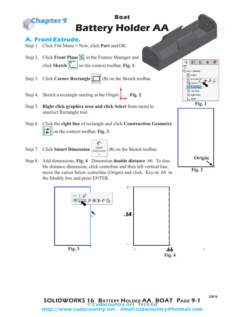
Battery Holder AA A. Front Extrude.Step 1. Click File Menu > New, click Part and OK.
Step 2. Click Front Plane in the Feature Manager and
click Sketch on the context toolbar, Fig. 1.
Step 3. Click Corner Rectangle (S) on the Sketch toolbar.
Step 4. Sketch a rectangle starting at the Origin , Fig. 2.
Step 5. Right click graphics area and click Select from menu to unselect Rectangle tool.
Step 6. Click the right line of rectangle and click Construction Geometry on the context toolbar, Fig. 3.
Step 7. Click Smart Dimension (S) on the Sketch toolbar.
Step 8. Add dimensions, Fig. 4. Dimension double distance .66. To dou-ble distance dimension, click centerline and then left vertical line, move the cursor below centerline (Origin) and click. Key-in .66 in the Modify box and press ENTER.
Chapter 9
2/8/16
Fig. 1
Fig. 2
Fig. 3
Origin
Fig. 4
© Cudacountry.net Tech Edhttp://www.cudacountry.net email:[email protected]

SOLIDWORKS 16 BatteRy HOLDeR aa BOat Page 9-2
Step 9. Click Sketch Fillet on the Sketch toolbar.
Step 10. In the Sketch Fillet Property Manager set: under Fillet Parameters, Fig. 5
Radius .2 click top left corner, Fig. 6 click OK twice.
Step 11. Drag a selection to select all geometry, Fig. 7.
Step 12. Click Mirror Entities on the
Sketch toolbar, Fig. 8.
B. Extrude Front Cut.Step 1. Click Features on the Command Manager toolbar.
Step 2. Click Extruded Boss/Base on the Features toolbar.
Step 3. In the Property Manager set: under Direction 1, Fig. 9 End Condition Mid Plane
Depth 2.22 click OK .
Step 4. Click Zoom to Fit (F) on the View toolbar.
Fig. 6
Fig. 8Fig. 7
Fig. 5
Drag selection to right
Fig. 9 Fig. 10

SOLIDWORKS 16 BatteRy HOLDeR aa BOat Page 9-3
C. Save as "BATTERY HOLDER".Step 1. Click File Menu > Save As.
Step 2. Key-in BATTERY HOLDER for the filename and press ENTER.
D. Side Cut.Step 1. Click side face of holder and click Sketch on
the context toolbar, Fig. 11.
Step 2. Click Normal To on the View toolbar. (Ctrl-8)
Step 3. Click Centerline in the
Line flyout on the Sketch toolbar.
Step 4. Starting from the Origin , sketch vertical centerline, Fig. 12.
Step 5. Click Line (L) on the Sketch toolbar.
Step 6. Sketch four lines, Fig. 13. Don’t forget line along the top edge of part up to the centerline.
Step 7. Click Smart Dimension
(S) on the Sketch toolbar.
Step 8. Add dimensions, Fig. 14.
Fig. 11
Side face
Fig. 12
Fig. 13
Fig. 14
Origin

SOLIDWORKS 16 BatteRy HOLDeR aa BOat Page 9-4
Step 9. Click Sketch Fillet on the Sketch toolbar.
Step 10. In the Sketch Fillet Property Manager set: under Fillet Parameters, Fig. 15
Radius .07 click the two corners, Fig. 16 click OK twice.
Step 11. Drag selection around sketch to select all entities, Fig. 17.
Step 12. Click Mirror Entities on the Sketch
toolbar, Fig. 18.
Step 13. Click Features on the Command Manager toolbar.
Step 14. Click Extruded Cut on the Features toolbar.
Step 15. In the Cut-Extrude Property Manager set: under Direction 1, Fig. 19 End Condition Through All check flip side to cut click OK .
Step 16. Save. Use Ctrl-S.
Fig. 15
Fig. 16
Fig. 17
Drag selection to right
Fig. 18
Fig. 19
Fig. 20
Fig. 21
Direction arrow

SOLIDWORKS 16 BatteRy HOLDeR aa BOat Page 9-5
E. Inside Cut.Step 1. Click Trimetric on the Standard Views toolbar.
Step 2. Click inside back face of holder and click Sketch on the context toolbar, Fig. 22.
Step 3. Click Normal To on the View toolbar. (Ctrl-8)
Step 4. Click Centerline in the Line flyout on the Sketch toolbar.
Step 5. Starting from the Origin , sketch vertical centerline up through part, Fig. 23.
Step 6. Click Line (L) on the Sketch toolbar.
Step 7. Sketch three lines, Fig. 24.
Step 8. Click Smart Dimension (S) on the Sketch toolbar.
Step 9. Add dimensions, Fig. 25.
Step 10. Click Tangent Arc in the Arc flyout on the Sketch toolbar.
Step 11. Sketch arc between top endpoint of vertical line and left endpoint of horizontal line, Position 1 and Posi-tion 2, Fig. 26. Start arc at Position 1 and swing up along path.
Inside back face
Fig. 22
Fig. 23
Fig. 24
Fig. 25
Origin
Fig. 26
Move arc along this
path
2
1
SOLIDWORKS 16 BatteRy HOLDeR aa BOat Page 9-6
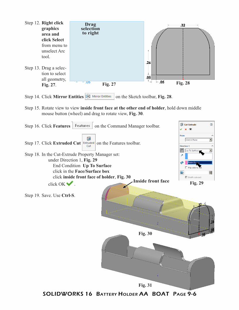
Step 12. Right click graphics area and click Select from menu to unselect Arc tool.
Step 13. Drag a selec-tion to select all geometry, Fig. 27.
Step 14. Click Mirror Entities on the Sketch toolbar, Fig. 28.
Step 15. Rotate view to view inside front face at the other end of holder, hold down middle mouse button (wheel) and drag to rotate view, Fig. 30.
Step 16. Click Features on the Command Manager toolbar.
Step 17. Click Extruded Cut on the Features toolbar.
Step 18. In the Cut-Extrude Property Manager set: under Direction 1, Fig. 29 End Condition Up To Surface click in the Face/Surface box click inside front face of holder, Fig. 30 click OK .
Step 19. Save. Use Ctrl-S.
Fig. 27
Drag selection to right
Fig. 29Inside front face
Fig. 31
Fig. 30
Fig. 28
SOLIDWORKS 16 BatteRy HOLDeR aa BOat Page 9-7
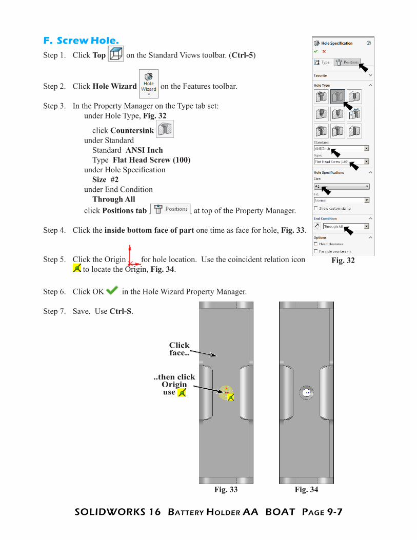
F. Screw Hole.Step 1. Click Top on the Standard Views toolbar. (Ctrl-5)
Step 2. Click Hole Wizard on the Features toolbar.
Step 3. In the Property Manager on the Type tab set: under Hole Type, Fig. 32
click Countersink under Standard Standard ANSI Inch Type Flat Head Screw (100) under Hole Specification Size #2 under End Condition Through All click Positions tab at top of the Property Manager.
Step 4. Click the inside bottom face of part one time as face for hole, Fig. 33.
Step 5. Click the Origin for hole location. Use the coincident relation icon to locate the Origin, Fig. 34.
Step 6. Click OK in the Hole Wizard Property Manager.
Step 7. Save. Use Ctrl-S.
Fig. 32
Fig. 33 Fig. 34
Click face..
..then click Origin use

SOLIDWORKS 16 BatteRy HOLDeR aa BOat Page 9-8
G. Lug Hole.Step 1. Click Trimetric on the Standard Views toolbar.
Step 2. Click outside front face of holder and click Sketch on the context toolbar, Fig. 35.
Step 3. Click Circle (S) on the Sketch toolbar.
Step 4. Sketch a circle, Fig. 36.
Step 5. Right click graphics area and click Select from menu to unselect Circle tool.
Step 6. Ctrl click centerpoint of circle and Origin
to select both. Release Ctrl key and
click Make Vertical on the context toolbar, Fig. 37.
Step 7. Click Smart Dimension (S) on the Sketch toolbar.
Step 8. Add dimensions, Fig. 38.
Step 9. Click Features on the Command Manager toolbar.
Step 10. Click Extruded Cut on the Features toolbar.
Step 11. In the Cut-Extrude Property Manager: under Direction 1, Fig. 39 End Condition Through All click OK .
Step 12. Save. Use Ctrl-S.
Fig. 35Outside front face
Fig. 40Fig. 39
Fig. 38
Fig. 37Fig. 36
Ctrl click center point and Origin

SOLIDWORKS 16 BatteRy HOLDeR aa BOat Page 9-9
H. Wire Cutout Hole.Step 1. Click outside front face of holder and click Sketch
on the context toolbar, Fig. 41.
Step 2. Click Circle (S) on the Sketch toolbar.
Step 3. Sketch a circle, Fig. 42.
Step 4. Click Smart Dimension (S) on the Sketch toolbar.
Step 5. Add dimensions, Fig. 43.
Step 6. Click Features on the Command Manager toolbar.
Step 7. Click Extruded Cut on the Features toolbar.
Step 8. In Cut-Extrude Property Manager: under Direction 1, Fig. 44
Depth .05 click OK .
Step 9. Save. Use Ctrl-S.
Fig. 41Outside front face
Fig. 44
Fig. 43Fig. 42
Fig. 46Fig. 45

SOLIDWORKS 16 BatteRy HOLDeR aa BOat Page 9-10
I. Mirror Wire Cutout Hole.Step 1. Ctrl click the Front Plane and Cut-Ex-
trude4 (Cutout Hole) in the Feature Manager to select both, Fig. 47.
Step 2. Click Mirror on the Features toolbar.
Step 3. In the Mirror Property Manager click OK .
Step 4. Save. Use Ctrl-S.
J. Fillet Edges.
Step 1. Click Fillet on the Features toolbar.
Step 2. In the Fillet Property Manager: select FilletXpert, Fig. 50 Radius .04 click bottom side edge, Fig. 51
click Internal to feature, 13 Edges on Fillet pop-up toolbar, Fig. 51 click OK .
Step 3. Save. Use Ctrl-S.
Fig. 48
Fig. 49
Fig. 47
Fig. 50
Fig. 52Fig. 51
Edge

SOLIDWORKS 16 BatteRy HOLDeR aa BOat Page 9-11
K. Enable SOLIDWORKS Routing.Step 1. If necessary, turn on SOLIDWORKS Routing, click the
flyout of Options on the Standard toolbar and click Add-Ins.
Step 2. In the dialog box place a check in the check box under SOLIDWORKS Routing Active Add-Ins and Start-Up, Fig. 53. Click OK.
L. Create C Points for Electrical Routing.Step 1. Click Tools Menu > Routing > Routing Tools > Create
Connection Point.
Step 2. In the Connection Point Property Manager set: under Selections, Fig. 54 click bottom edge of cutout hole, Fig. 55 under Route type select Electrical click Keep Visible and OK , Fig. 54. The
Push Pin on allows creation of another C Point.
Step 3. In the Connection Point Property Manager: under Selections, Fig. 56 rotate part to view bottom edge/face of rear cutout out hole, Fig. 57 click bottom edge of rear cutout hole, Fig. 57 C Point should point away from part, if in opposite direction, check Reverse direction. click OK and click Cancel .
Fig. 53
Fig. 54
Fig. 55
Fig. 56Fig. 57

SOLIDWORKS 16 BatteRy HOLDeR aa BOat Page 9-12
M. Appearance.Step 1. Click Trimetric on the Standard Views toolbar.
Step 2. Click part to select the part, click Appearance Call-
out on the context toolbar and click BAT-TERY... , Fig. 58.
Step 3. In the Appearances Task pane, expand Plastic, click High Gloss and in the lower pane select dark gray high gloss plastic, Fig. 59.
Step 4. Click OK in the Property Manager.
Step 5. Save. Use Ctrl-S.
Fig. 58
Click part
Fig. 60
Fig. 59
Fig. 61