Embed Size (px)
Citation preview
75LOW-VOLUME ROADS BMPS:
Chapter 8
CulvCulvCulvCulvCulvererererert Uset Uset Uset Uset Use, Installa, Installa, Installa, Installa, Installation,tion,tion,tion,tion,and Sizingand Sizingand Sizingand Sizingand Sizing
CULVERTS ARE commonly used both as cross-drains for ditch relief and to pass water undera road at natural drainage and stream
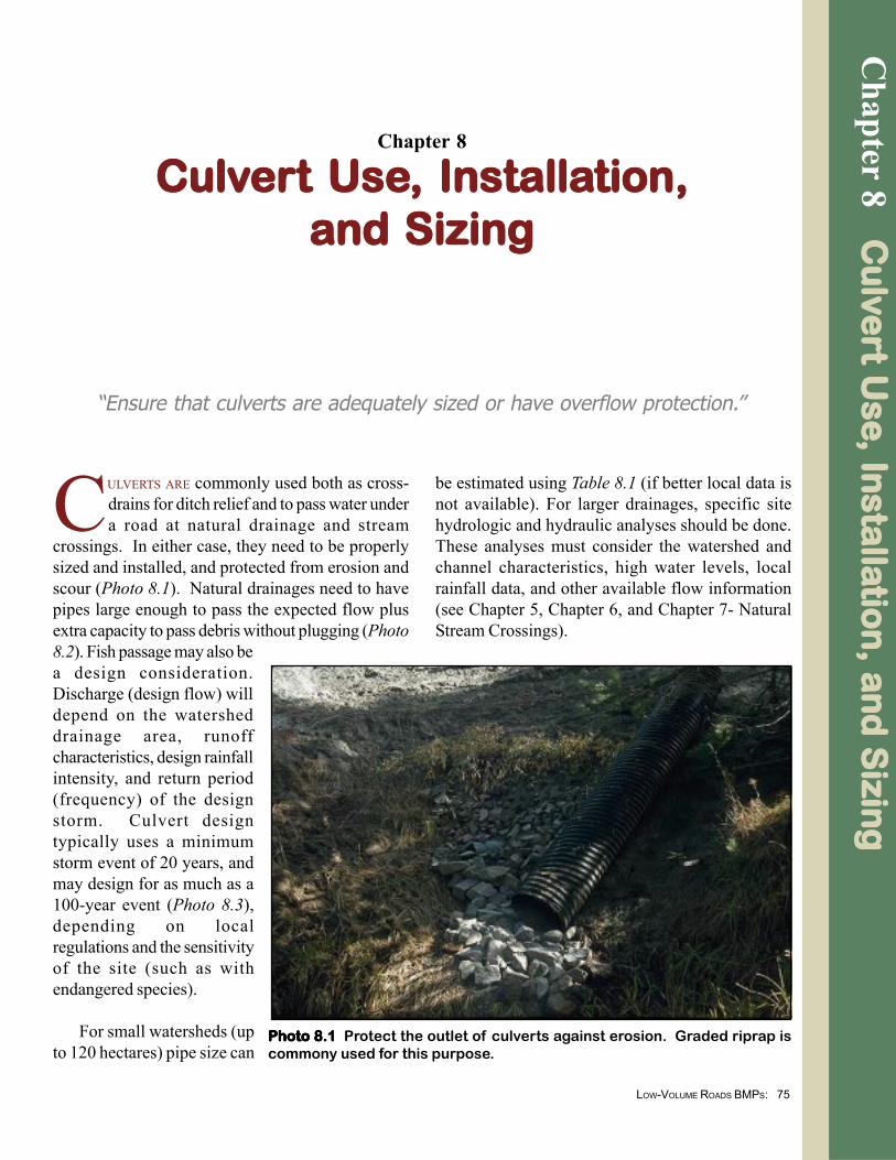
crossings. In either case, they need to be properlysized and installed, and protected from erosion andscour (Photo 8.1). Natural drainages need to havepipes large enough to pass the expected flow plusextra capacity to pass debris without plugging (Photo8.2). Fish passage may also bea design consideration.Discharge (design flow) willdepend on the watersheddrainage area, runoffcharacteristics, design rainfallintensity, and return period(frequency) of the designstorm. Culvert designtypically uses a minimumstorm event of 20 years, andmay design for as much as a100-year event (Photo 8.3),depending on localregulations and the sensitivityof the site (such as withendangered species).
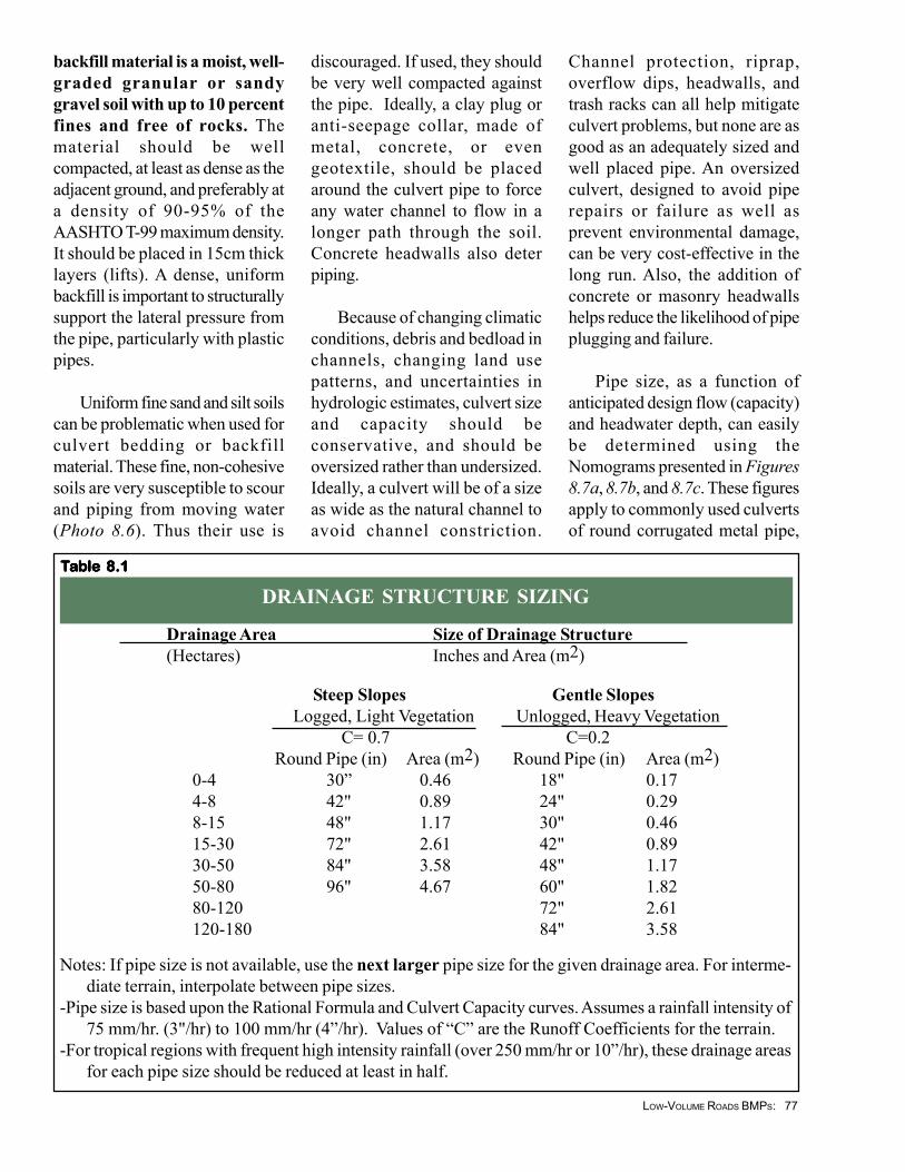
For small watersheds (upto 120 hectares) pipe size can
“Ensure that culverts are adequately sized or have overflow protection.”
Chapter 8 C
ulv
Cu
lvC
ulv
Cu
lvC
ulve
re
r ere
re
rt Use
t Use
t Use
t Use
t Use, In
stalla
, Insta
lla, In
stalla
, Insta
lla, In
stalla
tion
, an
d S
izing
tion
, an
d S
izing
tion
, an
d S
izing
tion
, an
d S
izing
tion
, an
d S
izing
be estimated using Table 8.1 (if better local data isnot available). For larger drainages, specific sitehydrologic and hydraulic analyses should be done.These analyses must consider the watershed andchannel characteristics, high water levels, localrainfall data, and other available flow information(see Chapter 5, Chapter 6, and Chapter 7- NaturalStream Crossings).
Photo 8.1 Photo 8.1 Photo 8.1 Photo 8.1 Photo 8.1 Protect the outlet of culverts against erosion. Graded riprap iscommony used for this purpose.
76LOW-VOLUME ROADS BMPS:
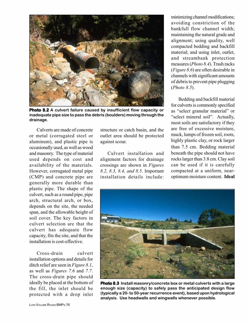
Photo 8.2Photo 8.2Photo 8.2Photo 8.2Photo 8.2 A culvert failure caused by insufficient flow capacity orinadequate pipe size to pass the debris (boulders) moving through thedrainage.
Photo 8.3Photo 8.3Photo 8.3Photo 8.3Photo 8.3 Install masonry/concrete box or metal culverts with a largeenough size (capacity) to safely pass the anticipated design flow(typically a 20- to 50-year recurrence event), based upon hydrologicalanalysis. Use headwalls and wingwalls whenever possible.
Culverts are made of concreteor metal (corrugated steel oraluminum), and plastic pipe isoccasionally used, as well as woodand masonry. The type of materialused depends on cost andavailability of the materials.However, corrugated metal pipe(CMP) and concrete pipe aregenerally more durable thanplastic pipe. The shape of theculvert, such as a round pipe, pipearch, structural arch, or box,depends on the site, the neededspan, and the allowable height ofsoil cover. The key factors inculvert selection are that theculvert has adequate flowcapacity, fits the site, and that theinstallation is cost-effective.
Cross-drain culvertinstallation options and details forditch relief are seen in Figure 8.1,as well as Figures 7.6 and 7.7.The cross-drain pipe shouldideally be placed at the bottom ofthe fill, the inlet should beprotected with a drop inlet
structure or catch basin, and theoutlet area should be protectedagainst scour.
Culvert installation andalignment factors for drainagecrossings are shown in Figures8.2, 8.3, 8.4, and 8.5. Importantinstallation details include:
minimizing channel modifications;avoiding constriction of thebankfull flow channel width;maintaining the natural grade andalignment; using quality, wellcompacted bedding and backfillmaterial; and using inlet, outlet,and streambank protectionmeasures (Photo 8.4). Trash racks(Figure 8.6) are often desirable inchannels with significant amountsof debris to prevent pipe plugging(Photo 8.5).
Bedding and backfill materialfor culverts is commonly specifiedas “select granular material” or“select mineral soil”. Actually,most soils are satisfactory if theyare free of excessive moisture,muck, lumps of frozen soil, roots,highly plastic clay, or rock largerthan 7.5 cm. Bedding materialbeneath the pipe should not haverocks larger than 3.8 cm. Clay soilcan be used if it is carefullycompacted at a uniform, near-optimum moisture content. Ideal
77LOW-VOLUME ROADS BMPS:
backfill material is a moist, well-graded granular or sandygravel soil with up to 10 percentfines and free of rocks. Thematerial should be wellcompacted, at least as dense as theadjacent ground, and preferably ata density of 90-95% of theAASHTO T-99 maximum density.It should be placed in 15cm thicklayers (lifts). A dense, uniformbackfill is important to structurallysupport the lateral pressure fromthe pipe, particularly with plasticpipes.
Uniform fine sand and silt soilscan be problematic when used forculvert bedding or backfillmaterial. These fine, non-cohesivesoils are very susceptible to scourand piping from moving water(Photo 8.6). Thus their use is
discouraged. If used, they shouldbe very well compacted againstthe pipe. Ideally, a clay plug oranti-seepage collar, made ofmetal, concrete, or evengeotextile, should be placedaround the culvert pipe to forceany water channel to flow in alonger path through the soil.Concrete headwalls also deterpiping.
Because of changing climaticconditions, debris and bedload inchannels, changing land usepatterns, and uncertainties inhydrologic estimates, culvert sizeand capacity should beconservative, and should beoversized rather than undersized.Ideally, a culvert will be of a sizeas wide as the natural channel toavoid channel constriction.
Channel protection, riprap,overflow dips, headwalls, andtrash racks can all help mitigateculvert problems, but none are asgood as an adequately sized andwell placed pipe. An oversizedculvert, designed to avoid piperepairs or failure as well asprevent environmental damage,can be very cost-effective in thelong run. Also, the addition ofconcrete or masonry headwallshelps reduce the likelihood of pipeplugging and failure.
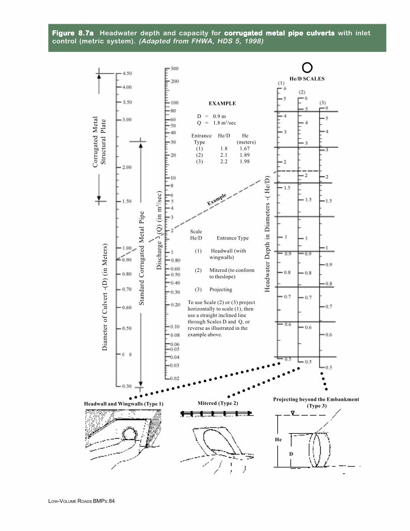
Pipe size, as a function ofanticipated design flow (capacity)and headwater depth, can easilybe determined using theNomograms presented in Figures8.7a, 8.7b, and 8.7c. These figuresapply to commonly used culvertsof round corrugated metal pipe,
DRAINAGE STRUCTURE SIZING
Drainage Area Size of Drainage Structure(Hectares) Inches and Area (m2)
Steep Slopes Gentle SlopesLogged, Light Vegetation Unlogged, Heavy Vegetation
C= 0.7 C=0.2Round Pipe (in) Area (m2) Round Pipe (in) Area (m2)
0-4 30” 0.46 18" 0.174-8 42" 0.89 24" 0.298-15 48" 1.17 30" 0.4615-30 72" 2.61 42" 0.8930-50 84" 3.58 48" 1.1750-80 96" 4.67 60" 1.8280-120 72" 2.61120-180 84" 3.58
Notes: If pipe size is not available, use the next larger pipe size for the given drainage area. For interme-diate terrain, interpolate between pipe sizes.
-Pipe size is based upon the Rational Formula and Culvert Capacity curves. Assumes a rainfall intensity of75 mm/hr. (3"/hr) to 100 mm/hr (4”/hr). Values of “C” are the Runoff Coefficients for the terrain.
-For tropical regions with frequent high intensity rainfall (over 250 mm/hr or 10”/hr), these drainage areasfor each pipe size should be reduced at least in half.
TTTTTaaaaabbbbble 8.1le 8.1le 8.1le 8.1le 8.1
78LOW-VOLUME ROADS BMPS:
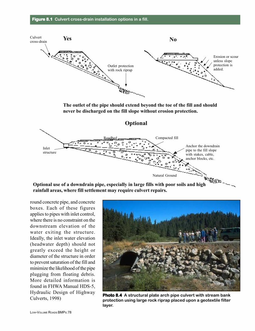
The outlet of the pipe should extend beyond the toe of the fill and shouldnever be discharged on the fill slope without erosion protection.
YesCulvertcross-drain
Outlet protectionwith rock riprap
No
Erosion or scourunless slopeprotection isadded.
Inletstructure
Compacted fill
Anchor the downdrainpipe to the fill slopewith stakes, cable,anchor blocks, etc.
Optional
Optional use of a downdrain pipe, especially in large fills with poor soils and highrainfall areas, where fill settlement may require culvert repairs.
Roadbed
Pipe
Natural Ground
FFFFFigurigurigurigurigure 8.1e 8.1e 8.1e 8.1e 8.1 Culvert cross-drain installation options in a fill.
Photo 8.4Photo 8.4Photo 8.4Photo 8.4Photo 8.4 A structural plate arch pipe culvert with stream bankprotection using large rock riprap placed upon a geotextile filterlayer.
round concrete pipe, and concreteboxes. Each of these figuresapplies to pipes with inlet control,where there is no constraint on thedownstream elevation of thewater exiting the structure.Ideally, the inlet water elevation(headwater depth) should notgreatly exceed the height ordiameter of the structure in orderto prevent saturation of the fill andminimize the likelihood of the pipeplugging from floating debris.More detailed information isfound in FHWA Manual HDS-5,Hydraulic Design of HighwayCulverts, 1998)
79LOW-VOLUME ROADS BMPS:
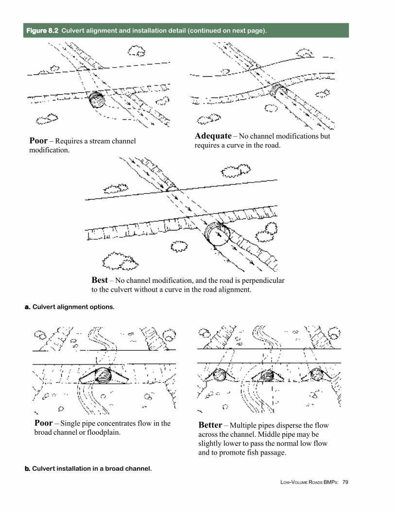
a. a. a. a. a. Culvert alignment options.
bbbbb. . . . . Culvert installation in a broad channel.
Poor – Single pipe concentrates flow in thebroad channel or floodplain.
Better – Multiple pipes disperse the flowacross the channel. Middle pipe may beslightly lower to pass the normal low flowand to promote fish passage.
Poor – Requires a stream channelmodification.
Adequate – No channel modifications butrequires a curve in the road.
Best – No channel modification, and the road is perpendicularto the culvert without a curve in the road alignment.
FFFFFigurigurigurigurigure 8.2 e 8.2 e 8.2 e 8.2 e 8.2 Culvert alignment and installation detail (continued on next page).
80LOW-VOLUME ROADS BMPS:
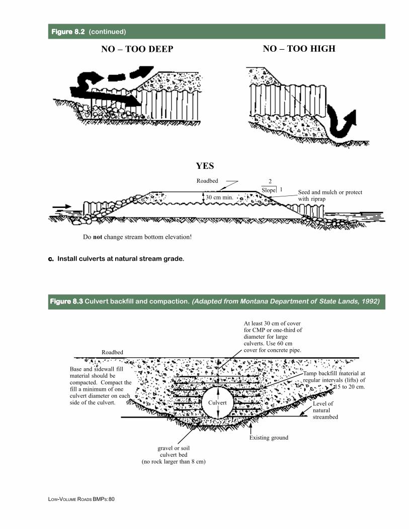
Slope 1
Do not change stream bottom elevation!
ccccc. . . . . Install culverts at natural stream grade.
YESRoadbed
Seed and mulch or protectwith riprap
2
NO – TOO DEEP NO – TOO HIGH
30 cm min.
FFFFFigurigurigurigurigure 8.2 e 8.2 e 8.2 e 8.2 e 8.2 (continued)
FFFFFigurigurigurigurigure 8.3 e 8.3 e 8.3 e 8.3 e 8.3 Culvert backfill and compaction. (Adapted from Montana Department of State Lands, 1992)
Roadbed
At least 30 cm of coverfor CMP or one-third ofdiameter for largeculverts. Use 60 cmcover for concrete pipe.
gravel or soilculvert bed
(no rock larger than 8 cm)
Tamp backfill material atregular intervals (lifts) of
15 to 20 cm.
Existing ground
Culvert Level ofnaturalstreambed
Base and sidewall fillmaterial should becompacted. Compact thefill a minimum of oneculvert diameter on eachside of the culvert.
81LOW-VOLUME ROADS BMPS:
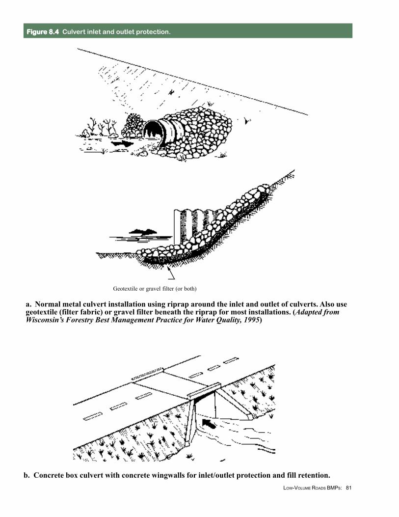
Geotextile or gravel filter (or both)
FFFFFigurigurigurigurigure 8.4e 8.4e 8.4e 8.4e 8.4 Culvert inlet and outlet protection.
a. Normal metal culvert installation using riprap around the inlet and outlet of culverts. Also usegeotextile (filter fabric) or gravel filter beneath the riprap for most installations. (Adapted fromWisconsin’s Forestry Best Management Practice for Water Quality, 1995)
b. Concrete box culvert with concrete wingwalls for inlet/outlet protection and fill retention.
82LOW-VOLUME ROADS BMPS:
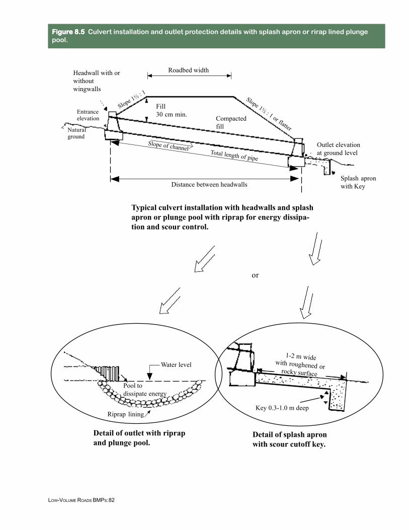
Typical culvert installation with headwalls and splashapron or plunge pool with riprap for energy dissipa-tion and scour control.
or
Roadbed width
Compactedfill
Fill30 cm min.Entrance
elevation
Naturalground
Headwall with orwithoutwingwalls
Total length of pipe
Slope of channel
Distance between headwalls
Slope 1½ : 1 Slope 1½ : 1 or flatter
Outlet elevationat ground level
Splash apronwith Key
Detail of outlet with riprapand plunge pool.
Detail of splash apronwith scour cutoff key.
Pool todissipate energy
Water level
Riprap liningKey 0.3-1.0 m deep
FFFFFigurigurigurigurigure 8.5 e 8.5 e 8.5 e 8.5 e 8.5 Culvert installation and outlet protection details with splash apron or rirap lined plungepool.
1-2 m widewith roughened orrocky surface
83LOW-VOLUME ROADS BMPS:
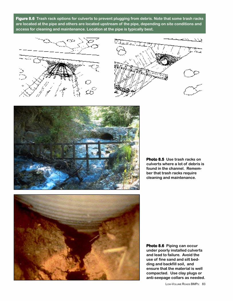
FFFFFigurigurigurigurigure 8.6 e 8.6 e 8.6 e 8.6 e 8.6 Trash rack options for culverts to prevent plugging from debris. Note that some trash racksare located at the pipe and others are located upstream of the pipe, depending on site conditions andaccess for cleaning and maintenance. Location at the pipe is typically best.
Photo 8.5 Photo 8.5 Photo 8.5 Photo 8.5 Photo 8.5 Use trash racks onculverts where a lot of debris isfound in the channel. Remem-ber that trash racks requirecleaning and maintenance.
Photo 8.6 Photo 8.6 Photo 8.6 Photo 8.6 Photo 8.6 Piping can occurunder poorly installed culvertsand lead to failure. Avoid theuse of fine sand and silt bed-ding and backfill soil, andensure that the material is wellcompacted. Use clay plugs oranti-seepage collars as needed.
84LOW-VOLUME ROADS BMPS:
FFFFFigurigurigurigurigure 8.7ae 8.7ae 8.7ae 8.7ae 8.7a Headwater depth and capacity for corcorcorcorcorrrrrrugugugugugaaaaated metal pipe culvted metal pipe culvted metal pipe culvted metal pipe culvted metal pipe culvererererertststststs with inletcontrol (metric system). (Adapted from FHWA, HDS 5, 1998)
Example
Cor
ruga
ted
Met
alSt
ruct
ural
Pla
teD
iam
eter
of
Cul
vert
-(D
) (i
n M
eter
s)
Dis
char
ge -
(Q
) (i
n m
3 /sec
)
Stan
dard
Cor
ruga
ted
Met
al P
ipe
Hea
dwat
er D
epth
in D
iam
eter
s -(
He/
D)
ScaleHe/D Entrance Type
(1) Headwall (withwingwalls)
(2) Mitered (to conformto theslope)
(3) Projecting
To use Scale (2) or (3) projecthorizontally to scale (1), thenuse a straight inclined linethrough Scales D and Q, orreverse as illustrated in theexample above.
○○○○○○○○○○○○○○○
○ ○ ○ ○ ○ ○ ○ ○ ○ ○ ○ ○ ○ ○ ○ ○ ○ ○ ○ ○ ○ ○ ○ ○ ○ ○ ○ ○ ○
○
○
○
○
He
D
He/D SCALES
EXAMPLE
D = 0.9 mQ = 1.8 m3/sec
Entrance He/D He Type (meters)
(1) 1.8 1.67(2) 2.1 1.89(3) 2.2 1.98
Mitered (Type 2)
∆∆∆∆∆
Headwall and Wingwalls (Type 1)Projecting beyond the Embankment
(Type 3)
85LOW-VOLUME ROADS BMPS:
Dis
char
ge -
(Q)
(in
m3 /s
ec)
Dia
met
er o
f th
e C
ulve
rt -
(D)
(in
Met
ers)
Hea
dwat
er D
epth
in D
iam
eter
s -
He/
D
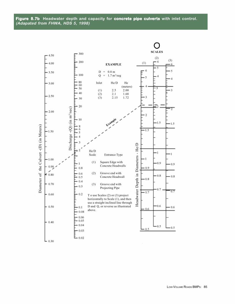
EXAMPLE
D = 0.8 mQ = 1.7 m3/seg
Inlet He/D He(meters)
(1) 2.5 2.00(2) 2.1 1.68(3) 2.15 1.72
Example
He/DScale Entrance Type
(1) Square Edge withConcrete Headwalls
(2) Groove end withConcrete Headwall
(3) Groove end withProjecting Pipe
T o use Scales (2) or (3) projecthorizontally to Scale (1), and thenuse a straight inclined line throughD and Q, or reverse as illustratedabove.
SCALES
FFFFFigurigurigurigurigure 8.7be 8.7be 8.7be 8.7be 8.7b Headwater depth and capacity for concrconcrconcrconcrconcrete pipe culvete pipe culvete pipe culvete pipe culvete pipe culvererererertststststs with inlet control.(Adapated from FHWA, HDS 5, 1998)
86LOW-VOLUME ROADS BMPS:
Rat
io o
f D
isch
arge
to W
idth
- (
Q/B
) (i
n m
3 /sec
/m)
Hei
ght o
f B
ox-
( D
) (i
n M
eter
s)
Hea
dwat
er D
epth
in T
erm
s of
Hei
ght -
( H
e/D
)
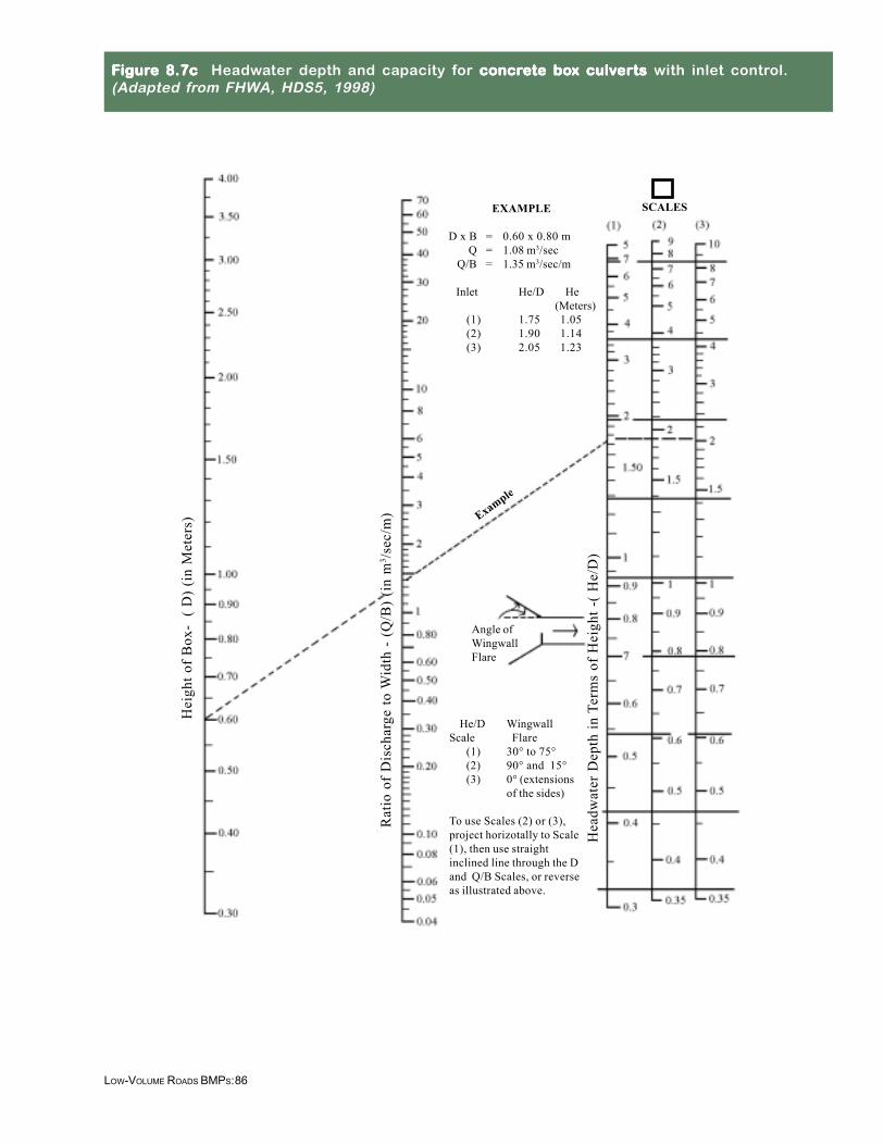
He/D WingwallScale Flare
(1) 30° to 75°(2) 90° and 15°(3) 0° (extensions
of the sides)
To use Scales (2) or (3),project horizotally to Scale(1), then use straightinclined line through the Dand Q/B Scales, or reverseas illustrated above.
Angle ofWingwallFlare
EXAMPLE
D x B = 0.60 x 0.80 mQ = 1.08 m3/sec
Q/B = 1.35 m3/sec/m
Inlet He/D He(Meters)
(1) 1.75 1.05(2) 1.90 1.14(3) 2.05 1.23
Example
SCALES
FFFFFigurigurigurigurigure 8.7c e 8.7c e 8.7c e 8.7c e 8.7c Headwater depth and capacity for concrconcrconcrconcrconcrete boete boete boete boete box culvx culvx culvx culvx culverererererts ts ts ts ts with inlet control.(Adapted from FHWA, HDS5, 1998)
87LOW-VOLUME ROADS BMPS:
RECOMMENDED PRACTICES
Ditch Relief Cross-DrainCulverts
• Ditch relief cross-drainpipes should typically havea diameter of 45 cm (mini-mum diameter of 30 cm).In areas with debris,unstable cut slopes, andraveling problems, use 60cm or larger pipes.
• Ditch relief cross-drainpipe grade should be atleast 2% more (steeper)than the ditch grade andskewed 0 to 30 degreesperpendicular to the road(see Figure 7.4). Thisadditional grade helps keepthe pipe from pluggingwith sediment.
• Ditch relief cross-drainsshould exit at the toe of thefill near natural groundlevel, at least 0.5 metersbeyond the toe of the fillslope. Armor the pipeoutlet (see Figures 7.6,7.7, and Figure 8.1).Don’t discharge the pipeon unprotected fill mate-rial, unstable slopes, ordirectly into streams (seePhoto 8.1 vs. Photo 8.9).
• In large fills, culvert down-drains may be needed tomove the water to the toeof the fill (Figure 8.1).Anchor downdrains to theslope with metal stakes,concrete anchor blocks, orcable. Pipes, flumes, orarmored ditches may beused.
Drainage Crossing Culverts• Install permanent culverts
with a size large enough topass design flood flows plusanticipated debris. Designfor 20- to 50-year stormevents. Sensitive streamsmay require designs to passa 100-year flood. Pipe sizecan be determined usinggeneral design criteria, suchas in Table 8.1, but is ideallybased upon site-specifichydrologic analysis.
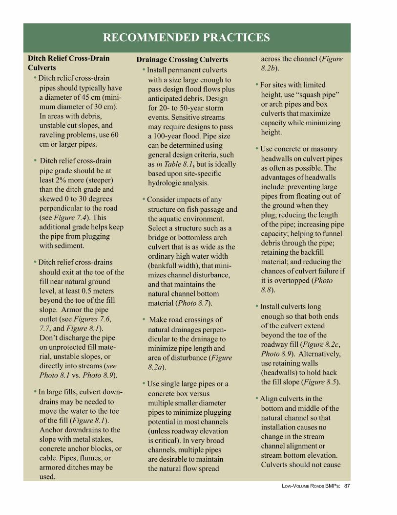
• Consider impacts of anystructure on fish passage andthe aquatic environment.Select a structure such as abridge or bottomless archculvert that is as wide as theordinary high water width(bankfull width), that mini-mizes channel disturbance,and that maintains thenatural channel bottommaterial (Photo 8.7).
• Make road crossings ofnatural drainages perpen-dicular to the drainage tominimize pipe length andarea of disturbance (Figure8.2a).
• Use single large pipes or aconcrete box versusmultiple smaller diameterpipes to minimize pluggingpotential in most channels(unless roadway elevationis critical). In very broadchannels, multiple pipesare desirable to maintainthe natural flow spread
across the channel (Figure8.2b).
• For sites with limitedheight, use “squash pipe”or arch pipes and boxculverts that maximizecapacity while minimizingheight.
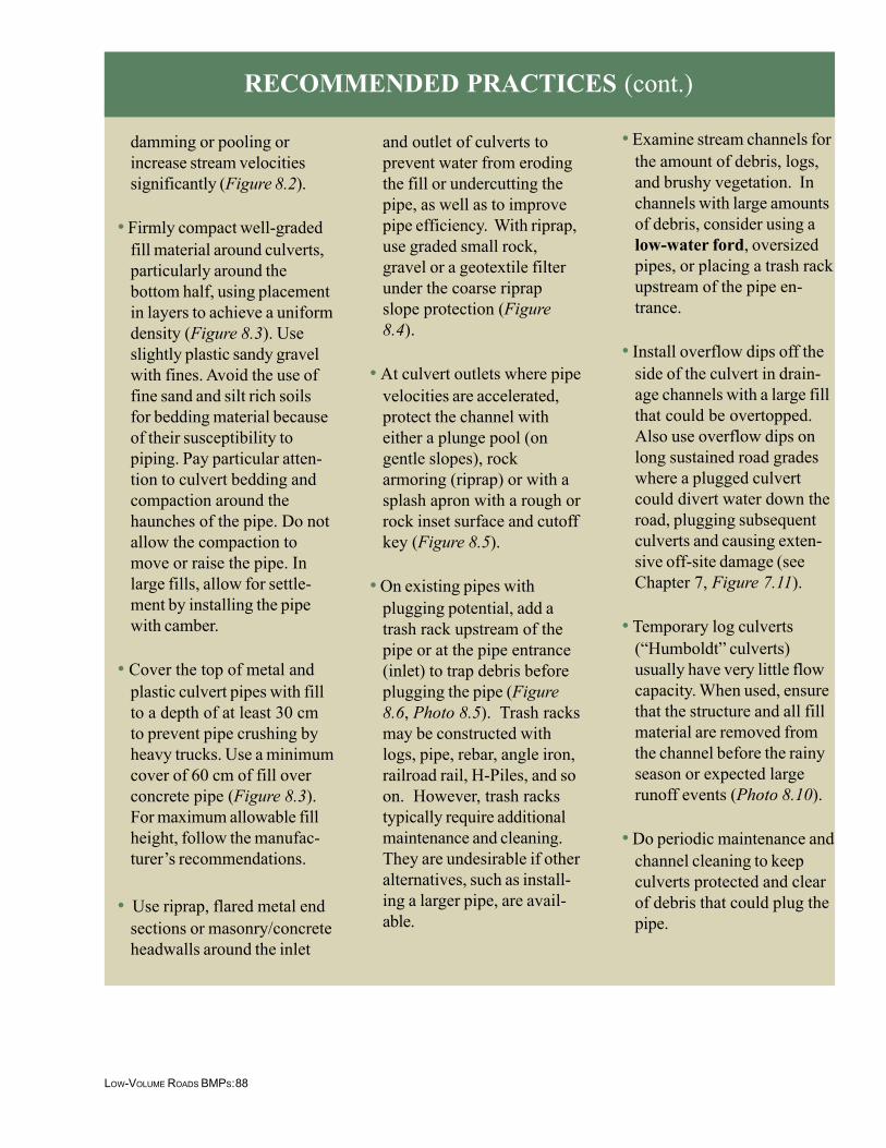
• Use concrete or masonryheadwalls on culvert pipesas often as possible. Theadvantages of headwallsinclude: preventing largepipes from floating out ofthe ground when theyplug; reducing the lengthof the pipe; increasing pipecapacity; helping to funneldebris through the pipe;retaining the backfillmaterial; and reducing thechances of culvert failure ifit is overtopped (Photo8.8).
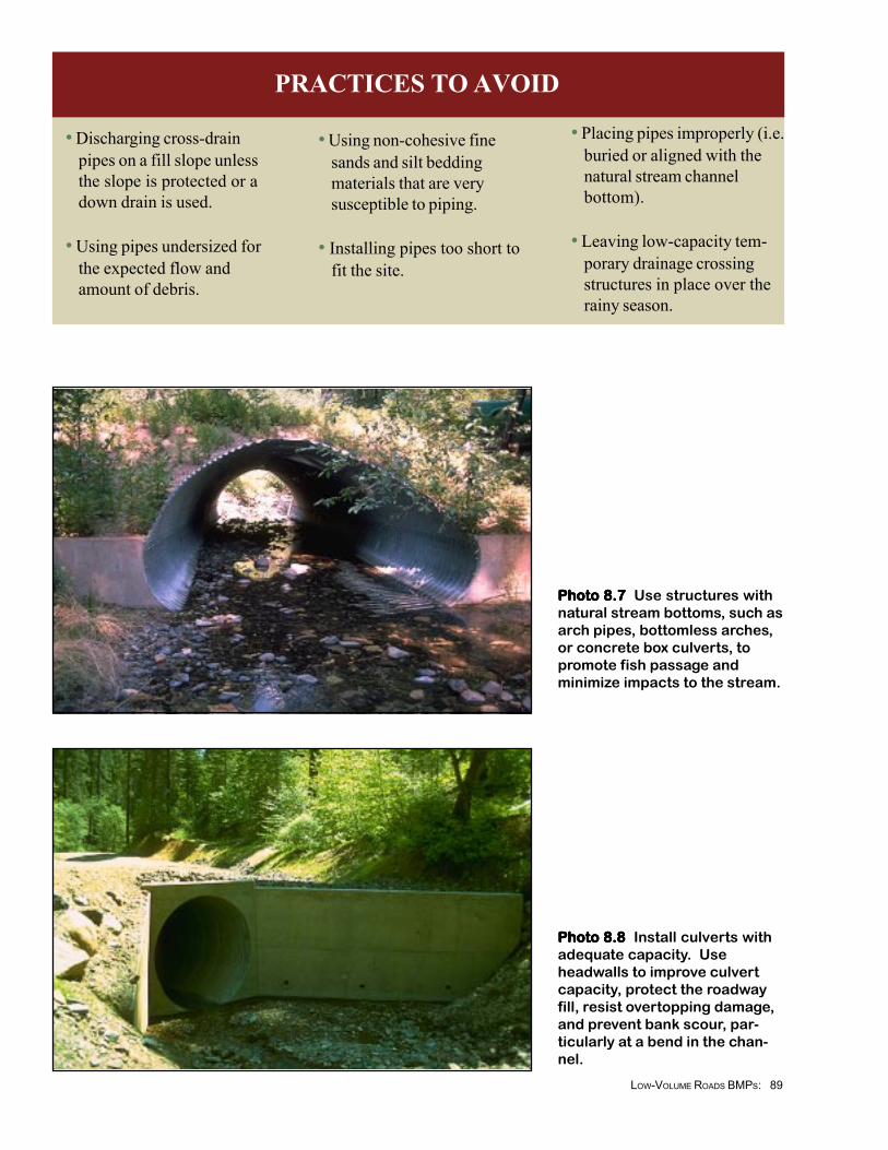
• Install culverts longenough so that both endsof the culvert extendbeyond the toe of theroadway fill (Figure 8.2c,Photo 8.9). Alternatively,use retaining walls(headwalls) to hold backthe fill slope (Figure 8.5).
• Align culverts in thebottom and middle of thenatural channel so thatinstallation causes nochange in the streamchannel alignment orstream bottom elevation.Culverts should not cause
88LOW-VOLUME ROADS BMPS:
damming or pooling orincrease stream velocitiessignificantly (Figure 8.2).
• Firmly compact well-gradedfill material around culverts,particularly around thebottom half, using placementin layers to achieve a uniformdensity (Figure 8.3). Useslightly plastic sandy gravelwith fines. Avoid the use offine sand and silt rich soilsfor bedding material becauseof their susceptibility topiping. Pay particular atten-tion to culvert bedding andcompaction around thehaunches of the pipe. Do notallow the compaction tomove or raise the pipe. Inlarge fills, allow for settle-ment by installing the pipewith camber.
• Cover the top of metal andplastic culvert pipes with fillto a depth of at least 30 cmto prevent pipe crushing byheavy trucks. Use a minimumcover of 60 cm of fill overconcrete pipe (Figure 8.3).For maximum allowable fillheight, follow the manufac-turer’s recommendations.
• Use riprap, flared metal endsections or masonry/concreteheadwalls around the inlet
and outlet of culverts toprevent water from erodingthe fill or undercutting thepipe, as well as to improvepipe efficiency. With riprap,use graded small rock,gravel or a geotextile filterunder the coarse riprapslope protection (Figure8.4).
• At culvert outlets where pipevelocities are accelerated,protect the channel witheither a plunge pool (ongentle slopes), rockarmoring (riprap) or with asplash apron with a rough orrock inset surface and cutoffkey (Figure 8.5).
• On existing pipes withplugging potential, add atrash rack upstream of thepipe or at the pipe entrance(inlet) to trap debris beforeplugging the pipe (Figure8.6, Photo 8.5). Trash racksmay be constructed withlogs, pipe, rebar, angle iron,railroad rail, H-Piles, and soon. However, trash rackstypically require additionalmaintenance and cleaning.They are undesirable if otheralternatives, such as install-ing a larger pipe, are avail-able.
• Examine stream channels forthe amount of debris, logs,and brushy vegetation. Inchannels with large amountsof debris, consider using alow-water ford, oversizedpipes, or placing a trash rackupstream of the pipe en-trance.
• Install overflow dips off theside of the culvert in drain-age channels with a large fillthat could be overtopped.Also use overflow dips onlong sustained road gradeswhere a plugged culvertcould divert water down theroad, plugging subsequentculverts and causing exten-sive off-site damage (seeChapter 7, Figure 7.11).
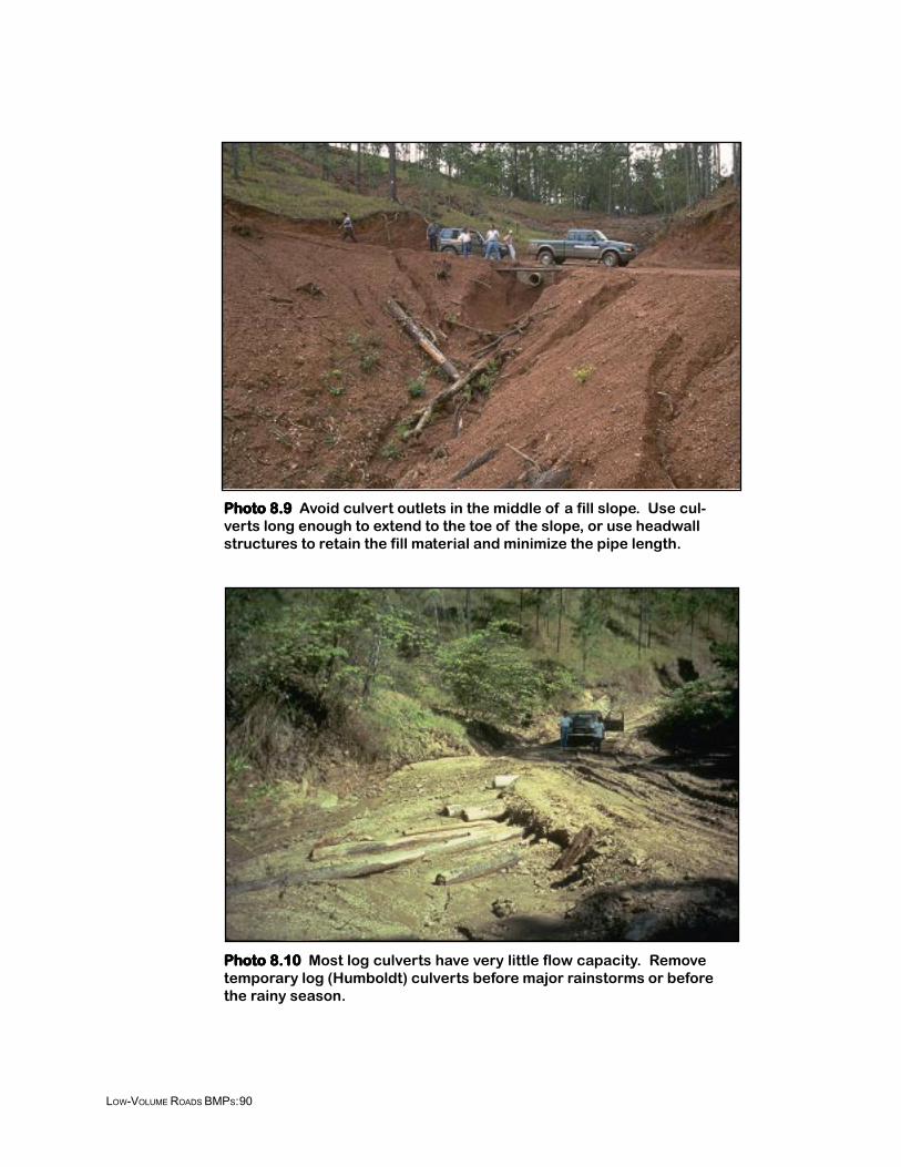
• Temporary log culverts(“Humboldt” culverts)usually have very little flowcapacity. When used, ensurethat the structure and all fillmaterial are removed fromthe channel before the rainyseason or expected largerunoff events (Photo 8.10).
• Do periodic maintenance andchannel cleaning to keepculverts protected and clearof debris that could plug thepipe.
RECOMMENDED PRACTICES (cont.)
89LOW-VOLUME ROADS BMPS:
PRACTICES TO AVOID
• Discharging cross-drainpipes on a fill slope unlessthe slope is protected or adown drain is used.
• Using pipes undersized forthe expected flow andamount of debris.
• Using non-cohesive finesands and silt beddingmaterials that are verysusceptible to piping.
• Installing pipes too short tofit the site.
• Placing pipes improperly (i.e.buried or aligned with thenatural stream channelbottom).
• Leaving low-capacity tem-porary drainage crossingstructures in place over therainy season.
Photo 8.7 Photo 8.7 Photo 8.7 Photo 8.7 Photo 8.7 Use structures withnatural stream bottoms, such asarch pipes, bottomless arches,or concrete box culverts, topromote fish passage andminimize impacts to the stream.
Photo 8.8 Photo 8.8 Photo 8.8 Photo 8.8 Photo 8.8 Install culverts withadequate capacity. Useheadwalls to improve culvertcapacity, protect the roadwayfill, resist overtopping damage,and prevent bank scour, par-ticularly at a bend in the chan-nel.
90LOW-VOLUME ROADS BMPS:
Photo 8.10Photo 8.10Photo 8.10Photo 8.10Photo 8.10 Most log culverts have very little flow capacity. Removetemporary log (Humboldt) culverts before major rainstorms or beforethe rainy season.
Photo 8.9Photo 8.9Photo 8.9Photo 8.9Photo 8.9 Avoid culvert outlets in the middle of a fill slope. Use cul-verts long enough to extend to the toe of the slope, or use headwallstructures to retain the fill material and minimize the pipe length.


![AVENTURA BRICKELL CITY CENTRE DOWNTOWN DADELAND … · AVENTURA BRICKELL CITY CENTRE DOWNTOWN DADELAND MIAMI BEACH Casa de Campo Mexico City JM JM JM JM JM JM JM JM [GF] Gluten freE](https://img.pdfslide.us/doc/110x75/5f3c14c92cc2286cb9022d6e/aventura-brickell-city-centre-downtown-dadeland-aventura-brickell-city-centre-downtown.jpg)